Embed Size (px)
Citation preview
2
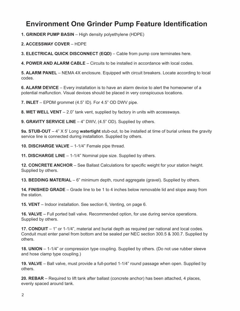
Environment One Grinder Pump Feature Identification1. GRINDER PUMP BASIN – High density polyethylene (HDPE)
2. ACCESSWAY COVER – HDPE
3. ELECTRICAL QUICK DISCONNECT (EQD) – Cable from pump core terminates here.
4. POWER AND ALARM CABLE – Circuits to be installed in accordance with local codes.
5. ALARM PANEL – NEMA 4X enclosure. Equipped with circuit breakers. Locate according to local codes.
6. ALARM DEVICE – Every installation is to have an alarm device to alert the homeowner of a potential malfunction. Visual devices should be placed in very conspicuous locations.
7. INLET – EPDM grommet (4.5” ID). For 4.5” OD DWV pipe.
8. WET WELL VENT – 2.0” tank vent, supplied by factory in units with accessways.
9. GRAVITY SERVICE LINE – 4” DWV, (4.5” OD). Supplied by others.
9a. STUB-OUT – 4” X 5’ Long watertight stub-out, to be installed at time of burial unless the gravity service line is connected during installation. Supplied by others.
10. DISCHARGE VALVE – 1-1/4” Female pipe thread.
11. DISCHARGE LINE – 1-1/4” Nominal pipe size. Supplied by others.
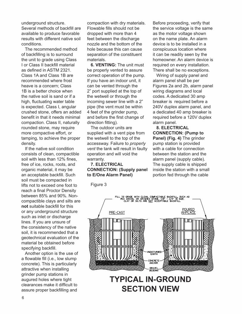
12. CONCRETE ANCHOR – See Ballast Calculations for specific weight for your station height. Supplied by others.
13. BEDDING MATERIAL – 6” minimum depth, round aggregate (gravel). Supplied by others.
14. FINISHED GRADE – Grade line to be 1 to 4 inches below removable lid and slope away from the station.
15. VENT – Indoor installation. See section 6, Venting, on page 6.
16. VALVE – Full ported ball valve. Recommended option, for use during service operations. Supplied by others.
17. CONDUIT – 1” or 1-1/4”, material and burial depth as required per national and local codes. Conduit must enter panel from bottom and be sealed per NEC section 300.5 & 300.7. Supplied by others.
18. UNION – 1-1/4” or compression type coupling. Supplied by others. (Do not use rubber sleeve and hose clamp type coupling.)
19. VALVE – Ball valve, must provide a full-ported 1-1/4” round passage when open. Supplied by others.
20. REBAR – Required to lift tank after ballast (concrete anchor) has been attached, 4 places, evenly spaced around tank.
3
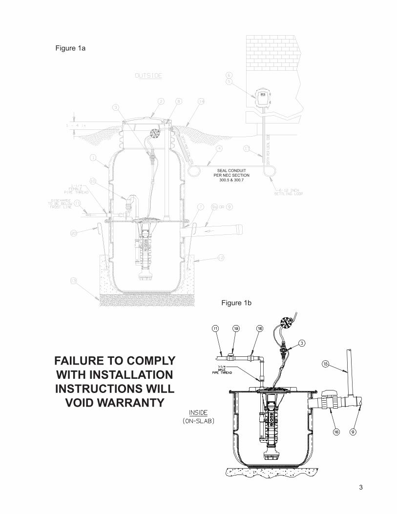
FAILURE TO COMPLY WITH INSTALLATION INSTRUCTIONS WILL
VOID WARRANTY
SEAL CONDUIT PER NEC SECTION
300.5 & 300.7
Figure 1b
Figure 1a
6
underground structure. Several methods of backfill are available to produce favorable results with different native soil conditions.
The recommended method of backfilling is to surround the unit to grade using Class I or Class II backfill material as defined in ASTM 2321. Class 1A and Class 1B are recommended where frost heave is a concern; Class 1B is a better choice when the native soil is sand or if a high, fluctuating water table is expected. Class I, angular crushed stone, offers an added benefit in that it needs minimal compaction. Class II, naturally rounded stone, may require more compactive effort, or tamping, to achieve the proper density.
If the native soil condition consists of clean, compactible soil with less than 12% fines, free of ice, rocks, roots, and organic material, it may be an acceptable backfill. Such soil must be compacted in lifts not to exceed one foot to reach a final Proctor Density between 85% and 90%. Non-compactible clays and silts are not suitable backfill for this or any underground structure such as inlet or discharge lines. If you are unsure of the consistency of the native soil, it is recommended that a geotechnical evaluation of the material be obtained before specifying backfill.
Another option is the use of a flowable fill (i.e., low slump concrete). This is particularly attractive when installing grinder pump stations in augured holes where tight clearances make it difficult to assure proper backfilling and
compaction with dry materials. Flowable fills should not be dropped with more than 4 feet between the discharge nozzle and the bottom of the hole because this can cause separation of the constituent materials.
6. VENTING: The unit must be properly vented to assure correct operation of the pump. If you have an indoor unit, it can be vented through the 2” port supplied at the top of the wetwell or through the incoming sewer line with a 2” pipe (the vent must be within 4 feet of the grinder pump, and before the first change of direction fitting).
The outdoor units are supplied with a vent pipe from the wetwell to the top of the accessway. Failure to properly vent the tank will result in faulty operation and will void the warranty.
7. ELECTRICAL CONNECTION: (Supply panel to E/One Alarm Panel)
Before proceeding, verify that the service voltage is the same as the motor voltage shown on the name plate. An alarm device is to be installed in a conspicuous location where it can be readily seen by the homeowner. An alarm device is required on every installation. There shall be no exceptions.
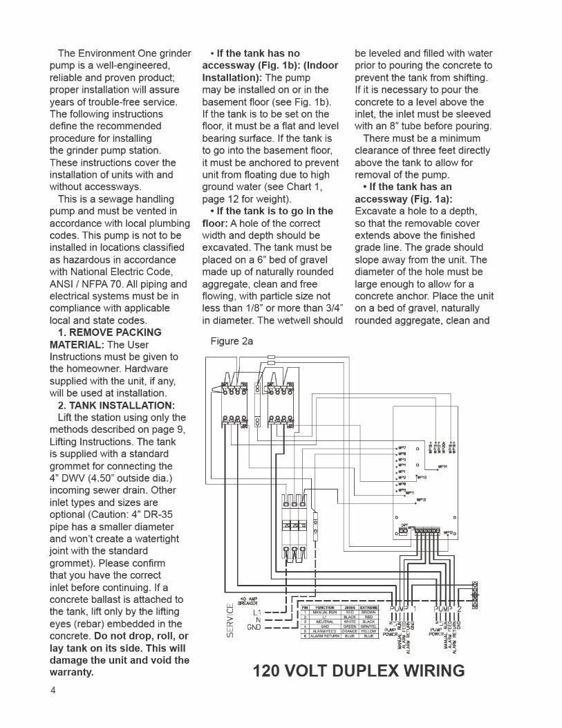
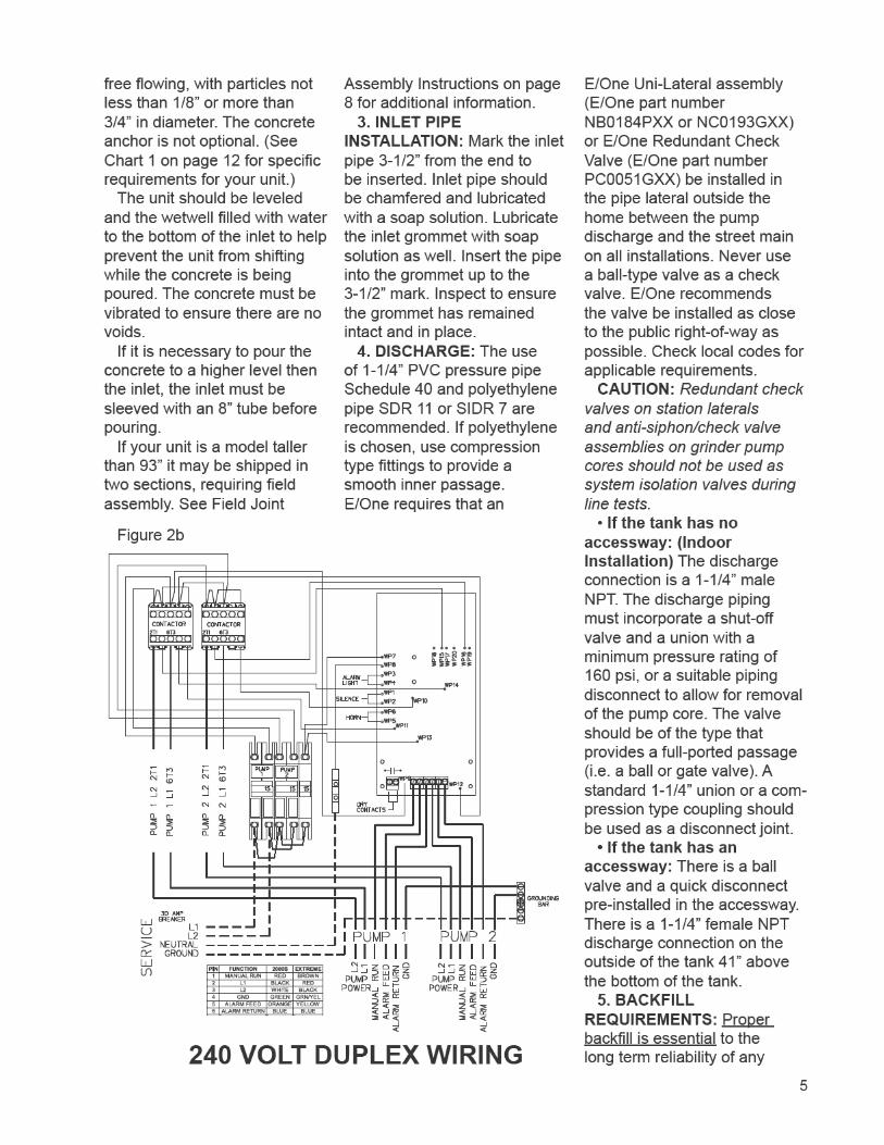
Wiring of supply panel and alarm panel shall be per Figures 2a and 2b, alarm panel wiring diagrams and local codes. A dedicated 30 amp breaker is required before a 240V duplex alarm panel, and a dedicated 40 amp breaker is required before a 120V duplex alarm panel.
8. ELECTRICAL CONNECTION: (Pump to Panel) (Fig. 4) The grinder pump station is provided with a cable for connection between the station and the alarm panel (supply cable). The supply cable is shipped inside the station with a small portion fed through the cable
TYPICAL IN-GROUND SECTION VIEW
Figure 3
7
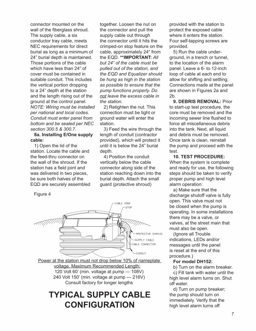
TYPICAL SUPPLY CABLE CONFIGURATION
Figure 4
connector mounted on the wall of the fiberglass shroud. The supply cable, a six conductor tray cable, meets NEC requirements for direct burial as long as a minimum of 24” burial depth is maintained. Those portions of the cable which have less than 24” of cover must be contained in suitable conduit. This includes the vertical portion dropping to a 24” depth at the station and the length rising out of the ground at the control panel. NOTE: Wiring must be installed per national and local codes. Conduit must enter panel from bottom and be sealed per NEC section 300.5 & 300.7.
8a. Installing E/One supply cable:
1) Open the lid of the station. Locate the cable and the feed-thru connector on the wall of the shroud. If the station has a field joint and was delivered in two pieces, be sure both halves of the EQD are securely assembled
together. Loosen the nut on the connector and pull the supply cable out through the connector until it hits the crimped-on stop feature on the cable, approximately 24” from the EQD. **IMPORTANT: All but 24” of the cable must be pulled out of the station, and the EQD and Equalizer should be hung as high in the station as possible to ensure that the pump functions properly. Do not leave the excess cable in the station.
2) Retighten the nut. This connection must be tight or ground water will enter the station.
3) Feed the wire through the length of conduit (contractor provided), which will protect it until it is below the 24” burial depth.
4) Position the conduit vertically below the cable connector along side of the station reaching down into the burial depth. Attach the small guard (protective shroud)
provided with the station to protect the exposed cable where it enters the station. Four self-tapping screws are provided.
5) Run the cable under-ground, in a trench or tunnel, to the location of the alarm panel. Leave a 6- to 12-inch loop of cable at each end to allow for shifting and settling. Connections made at the panel are shown in Figures 2a and 2b.
9. DEBRIS REMOVAL: Prior to start-up test procedure, the core must be removed and the incoming sewer line flushed to force all miscellaneous debris into the tank. Next, all liquid and debris must be removed. Once tank is clean, reinstall the pump and proceed with the test.
10. TEST PROCEDURE: When the system is complete and ready for use, the following steps should be taken to verify proper pump and high level alarm operation:
a) Make sure that the discharge shutoff valve is fully open. This valve must not be closed when the pump is operating. In some installations there may be a valve, or valves, at the street main that must also be open.
(Ignore all Trouble indications, LEDs and/or messages until the panel is reset at the end of this procedure.)
For model DH152:b) Turn on the alarm breaker.c) Fill tank with water until the
high level alarm turns on. Shut off water.
d) Turn on pump breaker; the pump should turn on immediately. Verify that the high level alarm turns off
Power at the station must not drop below 10% of nameplate voltage. Maximum Recommended Length:120 Volt 60’ (min. voltage at pump — 108V)240 Volt 150’ (min. voltage at pump — 216V)
Consult factory for longer lengths

8
and then the pump turns off. Proceed to Step E.
For model DR152:b) Fill tank with 100 gallons of
water.c) Turn on pump and alarm
breakers; the pump and high level alarm should turn on immediately.
d) Verify that the high level alarm turns off and then the pump turns off.
e) Clear/Reset the alarm panel:
Sentry and T260 panels: Reset is not required.
Protect Panel: Turn pump and alarm breakers off and back on simultaneously.
Protect Plus Panels: Perform a “cold start” from the Initialize System menu. Any user setting that were previously chosen will not be reset.
f) If any Trouble or alarm conditions are indicated after the panel is reset, contact your local service provider.
9
Field Joint Assembly Instructions
Parts included in Field Joint Kit: Identify all parts before proceeding with installation.
(16) 3/8-16 x 1-1/2 long screws(16) 3/8-16 Elastic Stop Nuts(32) Flat Washers(1) Length Sealant (Sika) Tape (1) Hole Punch(1) Vent Pipe Extension
1) Carefully clean and dry both accessway flanges with solvent. IMPORTANT: Sealing surfaces must be dry to ensure the sealant adheres correctly.
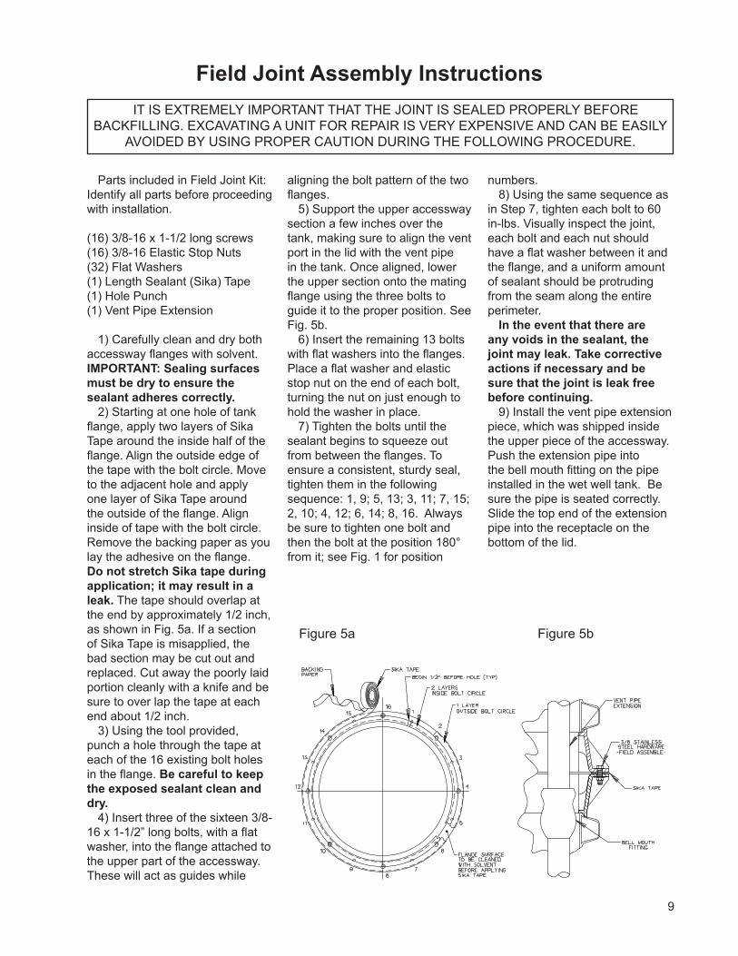
2) Starting at one hole of tank flange, apply two layers of Sika Tape around the inside half of the flange. Align the outside edge of the tape with the bolt circle. Move to the adjacent hole and apply one layer of Sika Tape around the outside of the flange. Align inside of tape with the bolt circle. Remove the backing paper as you lay the adhesive on the flange. Do not stretch Sika tape during application; it may result in a leak. The tape should overlap at the end by approximately 1/2 inch, as shown in Fig. 5a. If a section of Sika Tape is misapplied, the bad section may be cut out and replaced. Cut away the poorly laid portion cleanly with a knife and be sure to over lap the tape at each end about 1/2 inch.
3) Using the tool provided, punch a hole through the tape at each of the 16 existing bolt holes in the flange. Be careful to keep the exposed sealant clean and dry.
4) Insert three of the sixteen 3/8-16 x 1-1/2” long bolts, with a flat washer, into the flange attached to the upper part of the accessway. These will act as guides while
aligning the bolt pattern of the two flanges.
5) Support the upper accessway section a few inches over the tank, making sure to align the vent port in the lid with the vent pipe in the tank. Once aligned, lower the upper section onto the mating flange using the three bolts to guide it to the proper position. See Fig. 5b.
6) Insert the remaining 13 bolts with flat washers into the flanges. Place a flat washer and elastic stop nut on the end of each bolt, turning the nut on just enough to hold the washer in place.
7) Tighten the bolts until the sealant begins to squeeze out from between the flanges. To ensure a consistent, sturdy seal, tighten them in the following sequence: 1, 9; 5, 13; 3, 11; 7, 15; 2, 10; 4, 12; 6, 14; 8, 16. Always be sure to tighten one bolt and then the bolt at the position 180° from it; see Fig. 1 for position
numbers.8) Using the same sequence as
in Step 7, tighten each bolt to 60 in-lbs. Visually inspect the joint, each bolt and each nut should have a flat washer between it and the flange, and a uniform amount of sealant should be protruding from the seam along the entire perimeter.
In the event that there are any voids in the sealant, the joint may leak. Take corrective actions if necessary and be sure that the joint is leak free before continuing.
9) Install the vent pipe extension piece, which was shipped inside the upper piece of the accessway. Push the extension pipe into the bell mouth fitting on the pipe installed in the wet well tank. Be sure the pipe is seated correctly. Slide the top end of the extension pipe into the receptacle on the bottom of the lid.
IT IS EXTREMELY IMPORTANT THAT THE JOINT IS SEALED PROPERLY BEFORE BACKFILLING. EXCAVATING A UNIT FOR REPAIR IS VERY EXPENSIVE AND CAN BE EASILY
AVOIDED BY USING PROPER CAUTION DURING THE FOLLOWING PROCEDURE.
Figure 5a Figure 5b
10
Lifting Instructions
FAILURE TO FOLLOW THESE INSTRUCTIONS COMPLETELY WILL VOID WARRANTY.
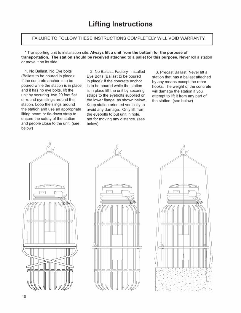
* Transporting unit to installation site: Always lift a unit from the bottom for the purpose of transportation. The station should be received attached to a pallet for this purpose. Never roll a station or move it on its side.
1. No Ballast, No Eye bolts (Ballast to be poured in place): If the concrete anchor is to be poured while the station is in place and it has no eye bolts, lift the unit by securing two 20 foot flat or round eye slings around the station. Loop the slings around the station and use an appropriate lifting beam or tie-down strap to ensure the safety of the station and people close to the unit. (see below)
2. No Ballast, Factory- Installed Eye Bolts (Ballast to be poured in place): If the concrete anchor is to be poured while the station is in place lift the unit by securing straps to the eyebolts supplied on the lower flange, as shown below. Keep station oriented vertically to avoid any damage. Only lift from the eyebolts to put unit in hole, not for moving any distance. (see below)
3. Precast Ballast: Never lift a station that has a ballast attached by any means except the rebar hooks. The weight of the concrete will damage the station if you attempt to lift it from any part of the station. (see below)
11
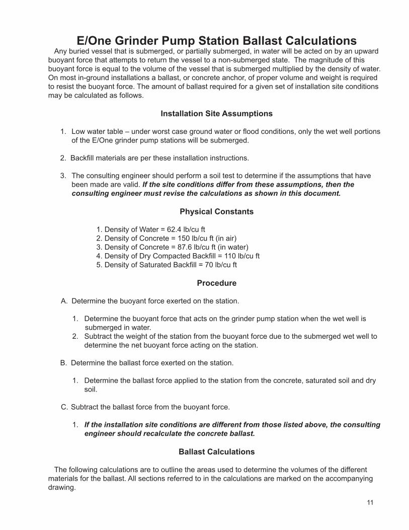
E/One Grinder Pump Station Ballast CalculationsAny buried vessel that is submerged, or partially submerged, in water will be acted on by an upward
buoyant force that attempts to return the vessel to a non-submerged state. The magnitude of this buoyant force is equal to the volume of the vessel that is submerged multiplied by the density of water. On most in-ground installations a ballast, or concrete anchor, of proper volume and weight is required to resist the buoyant force. The amount of ballast required for a given set of installation site conditions may be calculated as follows.
Installation Site Assumptions
1. Low water table – under worst case ground water or flood conditions, only the wet well portions of the E/One grinder pump stations will be submerged.
2. Backfill materials are per these installation instructions.
3. The consulting engineer should perform a soil test to determine if the assumptions that have been made are valid. If the site conditions differ from these assumptions, then the consulting engineer must revise the calculations as shown in this document.
Physical Constants
1. Density of Water = 62.4 lb/cu ft 2. Density of Concrete = 150 lb/cu ft (in air) 3. Density of Concrete = 87.6 lb/cu ft (in water) 4. Density of Dry Compacted Backfill = 110 lb/cu ft 5. Density of Saturated Backfill = 70 lb/cu ft
Procedure
A. Determine the buoyant force exerted on the station.
1. Determine the buoyant force that acts on the grinder pump station when the wet well is submerged in water.
2. Subtract the weight of the station from the buoyant force due to the submerged wet well to determine the net buoyant force acting on the station.
B. Determine the ballast force exerted on the station.
1. Determine the ballast force applied to the station from the concrete, saturated soil and dry soil.
C. Subtract the ballast force from the buoyant force.
1. If the installation site conditions are different from those listed above, the consulting engineer should recalculate the concrete ballast.
Ballast Calculations
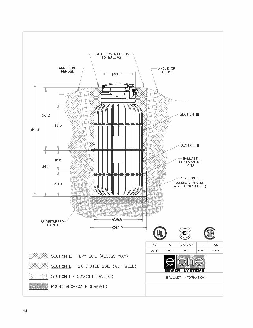
The following calculations are to outline the areas used to determine the volumes of the different materials for the ballast. All sections referred to in the calculations are marked on the accompanying drawing.
12
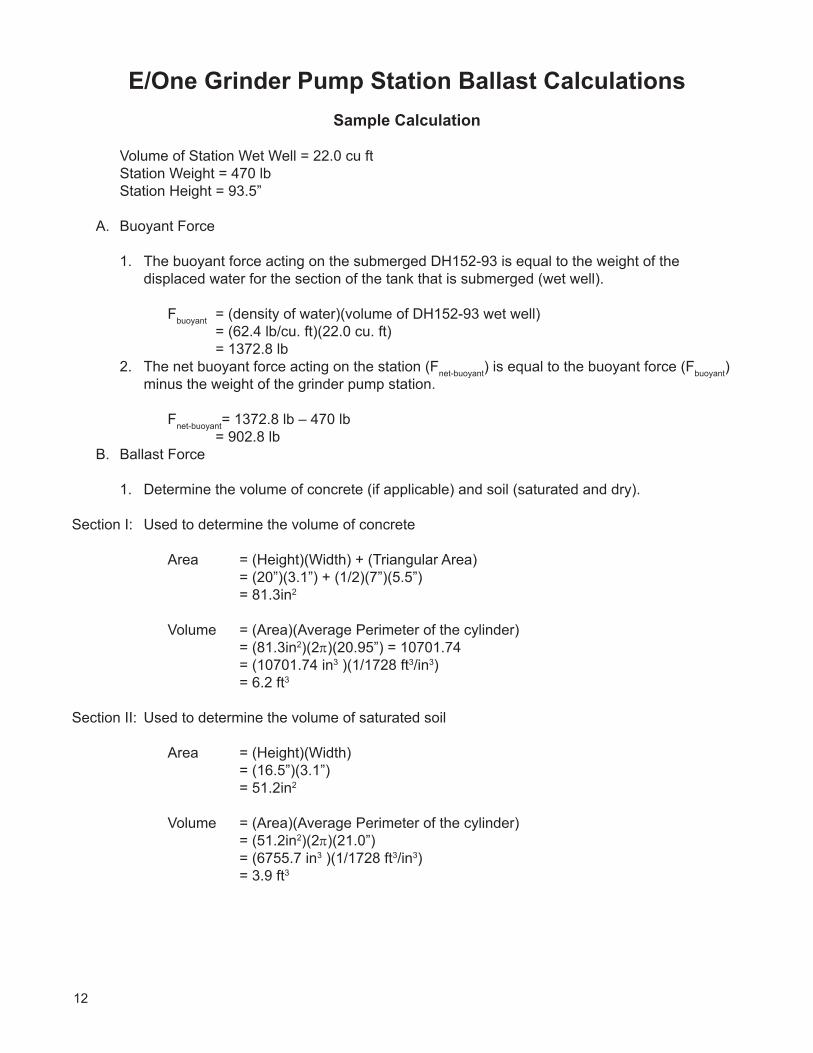
E/One Grinder Pump Station Ballast CalculationsSample Calculation
Volume of Station Wet Well = 22.0 cu ft Station Weight = 470 lb Station Height = 93.5”
A. Buoyant Force
1. The buoyant force acting on the submerged DH152-93 is equal to the weight of the displaced water for the section of the tank that is submerged (wet well).
Fbuoyant = (density of water)(volume of DH152-93 wet well) = (62.4 lb/cu. ft)(22.0 cu. ft) = 1372.8 lb
2. The net buoyant force acting on the station (Fnet-buoyant) is equal to the buoyant force (Fbuoyant) minus the weight of the grinder pump station.
Fnet-buoyant= 1372.8 lb – 470 lb = 902.8 lb
B. Ballast Force
1. Determine the volume of concrete (if applicable) and soil (saturated and dry).
Section I: Used to determine the volume of concrete
Area = (Height)(Width) + (Triangular Area) = (20”)(3.1”) + (1/2)(7”)(5.5”) = 81.3in2
Volume = (Area)(Average Perimeter of the cylinder) = (81.3in2)(2π)(20.95”) = 10701.74 = (10701.74 in3 )(1/1728 ft3/in3) = 6.2 ft3
Section II: Used to determine the volume of saturated soil
Area = (Height)(Width) = (16.5”)(3.1”) = 51.2in2
Volume = (Area)(Average Perimeter of the cylinder) = (51.2in2)(2π)(21.0”) = (6755.7 in3 )(1/1728 ft3/in3) = 3.9 ft3
13
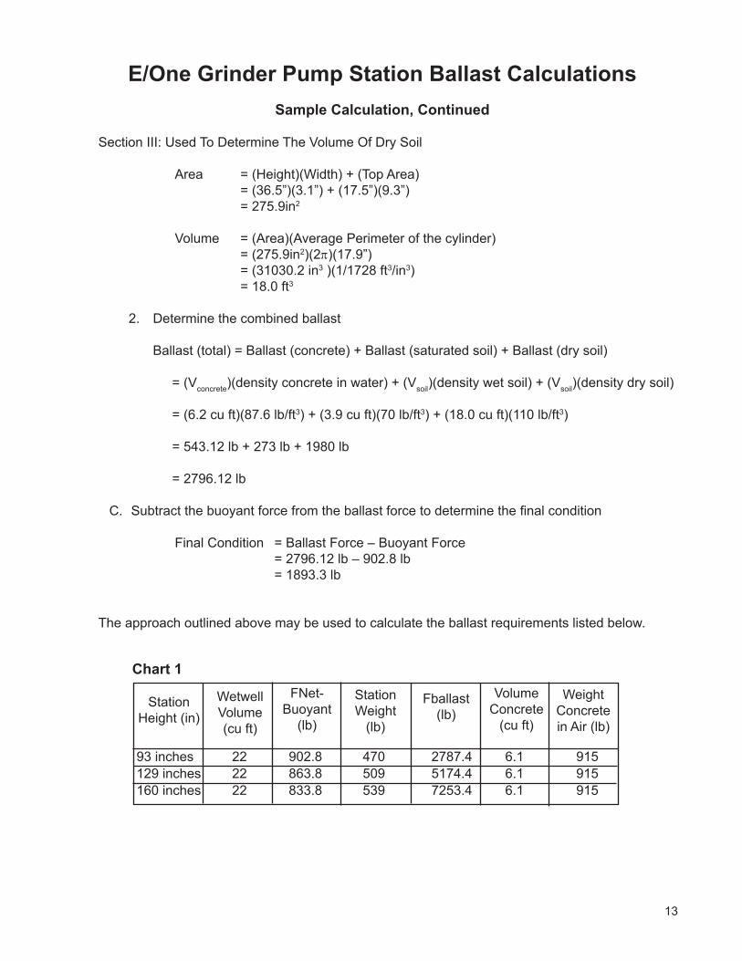
E/One Grinder Pump Station Ballast CalculationsSample Calculation, Continued
Section III: Used To Determine The Volume Of Dry Soil
Area = (Height)(Width) + (Top Area) = (36.5”)(3.1”) + (17.5”)(9.3”) = 275.9in2
Volume = (Area)(Average Perimeter of the cylinder) = (275.9in2)(2π)(17.9”) = (31030.2 in3 )(1/1728 ft3/in3) = 18.0 ft3
2. Determine the combined ballast
Ballast (total) = Ballast (concrete) + Ballast (saturated soil) + Ballast (dry soil) = (Vconcrete)(density concrete in water) + (Vsoil)(density wet soil) + (Vsoil)(density dry soil)
= (6.2 cu ft)(87.6 lb/ft3) + (3.9 cu ft)(70 lb/ft3) + (18.0 cu ft)(110 lb/ft3)
= 543.12 lb + 273 lb + 1980 lb
= 2796.12 lb
C. Subtract the buoyant force from the ballast force to determine the final condition
Final Condition = Ballast Force – Buoyant Force = 2796.12 lb – 902.8 lb = 1893.3 lb
The approach outlined above may be used to calculate the ballast requirements listed below.
Chart 1
Station Height (in)
Wetwell Volume (cu ft)
FNet-Buoyant
(lb)
Station Weight
(lb)
Fballast (lb)
Volume Concrete
(cu ft)
Weight Concrete in Air (lb)
93 inches 22 902.8 470 2787.4 6.1 915129 inches 22 863.8 509 5174.4 6.1 915160 inches 22 833.8 539 7253.4 6.1 915
14
15
Adjusting the Height of the Grinder Pump StationTO INCREASE STATION HEIGHT 6 INCHES1. Increasing station height can be done without cutting the station. Use the E/One Extender cover shroud
kit (ND0082G01) and follow the instructions that are included with the kit.
TO INCREASE STATION HEIGHT MORE THAN 6 INCHES or TO REDUCE THE STATION HEIGHT:
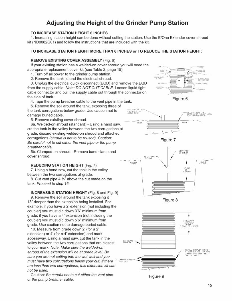
REMOVE EXISTING COVER ASSEMBLY (Fig. 6)If your existing station has a welded-on cover shroud you will need the
appropriate replacement cover kit (see Table 2, page 15).1. Turn off all power to the grinder pump station.2. Remove the tank lid and the electrical shroud.3. Unplug the electrical quick disconnect (EQD) and remove the EQD
from the supply cable. Note: DO NOT CUT CABLE. Loosen liquid tight cable connector and pull the supply cable out through the connector on the side of tank.
4. Tape the pump breather cable to the vent pipe in the tank.5. Remove the soil around the tank, exposing three of
the tank corrugations below grade. Use caution not to damage buried cable.
6. Remove existing cover shroud.6a. Welded-on shroud (standard) - Using a hand saw,
cut the tank in the valley between the two corrugations at grade, discard existing welded-on shroud and attached corrugations (shroud is not to be reused). Caution: Be careful not to cut either the vent pipe or the pump breather cable.
6b. Clamped-on shroud - Remove band clamp and cover shroud.
REDUCING STATION HEIGHT (Fig. 7)7. Using a hand saw, cut the tank in the valley
between the two corrugations at grade.8. Cut vent pipe 4 ¾” above the cut made on the
tank. Proceed to step 16.
INCREASING STATION HEIGHT (Fig. 8 and Fig. 9)9. Remove the soil around the tank exposing it
18” deeper than the extension being installed. For example, if you have a 2’ extension (not including the coupler) you must dig down 3’6” minimum from grade; if you have a 4’ extension (not including the coupler) you must dig down 5’6” minimum from grade. Use caution not to damage buried cable.
10. Measure from grade down 2’ (for a 2’ extension) or 4’ (for a 4’ extension) and mark accessway. Using a hand saw, cut the tank in the valley between the two corrugations that are closest to your mark. Note: Make sure the welded-on shroud of the extension will be at grade level. Be sure you are not cutting into the wet well and you must have two corrugations below your cut, if there are less than two corrugations, this extension kit can not be used.
Caution: Be careful not to cut either the vent pipe or the pump breather cable.
Figure 6
Figure 7
Figure 8
Figure 9
16
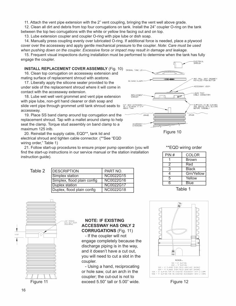
11. Attach the vent pipe extension with the 2” vent coupling, bringing the vent well above grade.12. Clean all dirt and debris from top four corrugations on tank. Install the 24” coupler O-ring on the tank
between the top two corrugations with the white or yellow line facing out and on top.13. Lube extension coupler and coupler O-ring with pipe lube or dish soap.14. Manually press coupling evenly over lubricated O-ring. If additional force is needed, place a plywood
cover over the accessway and apply gentle mechanical pressure to the coupler. Note: Care must be used when pushing down on the coupler. Excessive force or impact may result in damage and leakage.
15. Frequent visual inspections during installation must be performed to determine when the tank has fully engage the coupler.
INSTALL REPLACEMENT COVER ASSEMBLY (Fig. 10)16. Clean top corrugation on accessway extension and
mating surface of replacement shroud with acetone. 17. Liberally apply the silicone sealer provided to the
under side of the replacement shroud where it will come in contact with the accessway extension.
18. Lube wet well vent grommet and vent pipe extension with pipe lube, non-grit hand cleaner or dish soap and slide vent pipe through grommet until tank shroud seats to accessway.
19. Place SS band clamp around top corrugation and the replacement shroud. Tap with a mallet around clamp to help seat the clamp. Torque stud assembly on band clamp to a maximum 125 inlb.
20. Reinstall the supply cable, EQD**, tank lid and electrical shroud and tighten cable connector. (**See “EQD wiring order,” Table 1)
21. Follow start-up procedures to ensure proper pump operation (you will find the start-up instructions in our service manual or the station installation instruction guide). PIN # COLOR
1 Brown 2 Red 3 Black 4 Grn/Yellow 5 Yellow 6 Blue
**EQD wiring order
Table 1
NOTE: IF EXISTING ACCESSWAY HAS ONLY 2 CORRUGATIONS (Fig. 11)
- If the coupler will not engage completely because the discharge piping is in the way, and it doesn’t have a cut out, you will need to cut a slot in the coupler.
- Using a hand, reciprocating or hole saw, cut an arch in the coupler; the cut-out is not to exceed 5.50” tall or 5.00” wide.Figure 11 Figure 12
Table 2
Figure 10
NC0028
DESCRIPTION PART NO.Simplex station NC0022G15Simplex, flood plain config NC0022G16Duplex station NC0022G17Duplex, flood plain config NC0022G18

17

18
Environment One Corporation2773 Balltown RoadNiskayuna, New York 12309–1090
Voice: (01) 518.346.6161Fax: 518.346.6188
www.eone.com NA0063P01 Rev H5/16
A Precision Castparts Company
19
User Instructions for the Environment One Grinder PumpGeneral InformationYour home is served by a low pressure sewer system; the key element is an Environment One grinder pump. The tank collects all solid materials and wastewater from the house. The solid materials are then ground to a small size suitable for pumping as a slurry with the wastewater. The grinder pump generates sufficient pressure to pump this slurry from your home to the wastewater treatment receiving line and/or disposal plant.
This device complies with Part 15 of the FCC rules. Operation is subject to the following two conditions: 1) this device may not cause harmful interference; and 2) this device must accept any interference received, including interference that may cause undesired operation. Any changes or modifications not expressly approved by the party responsible for compliance could void the user’s authority to operate this equipment.
Care and Use of your Grinder PumpThe Environment One grinder pump is capable of accepting and pumping a wide range of materials, and an extensive grind test is required in order to obtain NSF approval. However, regulatory agencies advise that the following items should not be introduced into any sewer, either directly or through a kitchen waste disposal unit:
Glass Seafood shells Diapers, socks, rags or cloth Syringes
Cotton swabs Personal/cleaning wipes & sponges Disposable toothbrushes Latex/vinyl items
Metal Plastic objects (toys, utensils, etc.) Kitty litter Dental floss
Aquarium gravel Sanitary napkins or tampons Cigarette butts
Caution: Kitchen garbage disposals do not keep grease/oil out of the plumbing system
In addition, you must never introduce into any sewer:
Explosives Strong chemicals Lubricating oil and/or grease
Flammable material Gasoline
Items introduced into the sewer system from your home can potentially impact the water environment. Proper disposal of household wastes such as window cleaners, unused/expired pharmaceuticals, paint thinners, fats, fruit labels, etc. is important. For more information, visit http://www.wef.org.
Periods of DisuseIf your home or building is left unoccupied for longer than a couple of weeks, perform the following procedure:
Purge the System. Run clean water into the unit until the pump activates. Immediately turn off the water and allow the grinder pump to run until it shuts off automatically.
Duplex Units. Special attention must be taken to ensure that both pumps turn on when clean water is added to the tank.
Caution: Do not disconnect power to the unit
Power FailureYour grinder pump cannot dispose of wastewater without electrical power. If electrical power service is interrupted, keep water usage to a minimum.
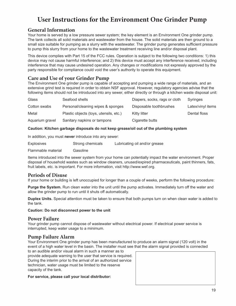
Pump Failure AlarmYour Environment One grinder pump has been manufactured to produce an alarm signal (120 volt) in the event of a high water level in the basin. The installer must see that the alarm signal provided is connected to an audible and/or visual alarm in such a manner as to provide adequate warning to the user that service is required. During the interim prior to the arrival of an authorized service technician, water usage must be limited to the reserve capacity of the tank.
For service, please call your local distributor:

SEWER SYSTEMS2773 Balltown Rd • Niskayuna NY USA 12309
(01) 518.346.6161 • www.eone.com
Environment One Corporation offers a limited warranty that guarantees its product to be free from defects in material and factory workmanship for a period of two years from the date of installation, or 27 months from the date of shipment, whichever occurs first, provided the product is properly installed, serviced and operated under normal conditions and according to manufacturer’s instructions. Repair or parts replacement required as a result of such defect will be made free of charge during this period upon return of the defective parts or equipment to the manufacturer or its nearest authorized service center.
Limited WarrantyFor E/One Extreme D-Series,
W-Series & Upgrade
Model Number: ______________________
Serial Number: _______________________
Installation Date: _____________________
E/One SewersTM


![Profiling Memory in Lua · 77.20 999 MB 1295 MB 1 main chunk (main.lua) 8.65 112 MB 112 MB 147 insert [C] 7.01 91 MB 91 MB 1,000,001 for iterator [C] 5.89 76 MB 76 MB 1,000,000 gmatch](https://img.pdfslide.us/doc/110x75/6020bbf0c069bf413e212b0e/profiling-memory-in-lua-7720-999-mb-1295-mb-1-main-chunk-mainlua-865-112-mb.jpg)