Embed Size (px)
Citation preview

Professional, Creditable, Successful DGUS Development Guide V3.4.0
3
DGUS Development Guide
V3.4
Revision in May, 2013
AMP DISPLAY INC.

Professional, Creditable, Successful DGUS Development Guide V3.4
1
Contents Contents .................................................................................................................................................................................. 1 INTRODUCTION .................................................................................................................................................................... 1 1 Hardware.............................................................................................................................................................................. 4
1.1 SD Card Slot ................................................................................................................................................................ 6 1.2 CONFIG.TXT ................................................................................................................................................................ 7 1.3 Memory Space ............................................................................................................................................................. 9 1.4 Firmware Upgrade ..................................................................................................................................................... 11 1.5 Touch Screen Calibration ......................................................................................................................................... 13 1.6 Enable/Disable SD Card .......................................................................................................................................... 13 1.7 User program based on DWIN OS ......................................................................................................................... 14
2 Serial Port .......................................................................................................................................................................... 15 2.1 Data Frame ................................................................................................................................................................. 15 2.2 Command Set ............................................................................................................................................................ 16
3 Data Format ....................................................................................................................................................................... 16 4 Touch Config. File (13.BIN) ............................................................................................................................................. 17
4.1 Variable Data Input (0x00) ........................................................................................................................................ 17 4.2 Popup Window (0x01) .............................................................................................................................................. 19 4.3 Incremental Adjustment (0x02) ................................................................................................................................ 20 4.4 Slider Adjustment (0x03) .......................................................................................................................................... 21 4.5 The RTC Settings (0x04) .......................................................................................................................................... 22 4.6 Return Key Code (0x05) ........................................................................................................................................... 23 4.7 Text Input (0x06) ........................................................................................................................................................ 23 4.8 Firmware Parameter Settings (0x07) ...................................................................................................................... 26
5 Variable Config. File (14.BIN) ......................................................................................................................................... 27 5.1 Variable Icon ............................................................................................................................................................... 27
5.1.1 Variable Icon (0x00) ........................................................................................................................................... 27 5.1.2 Animation Icon (0x01) ........................................................................................................................................ 28 5.1.3 Slider (0x02) ........................................................................................................................................................ 29 5.1.4 WordArt (0x03) ................................................................................................................................................... 30 5.1.5 Image Animation (0x04) .................................................................................................................................... 31 5.1.6 Icon Rotation (0x05) ........................................................................................................................................... 32 5.1.7 Bit Variable Icon (0x06) ..................................................................................................................................... 33
5.2 Text Variable ............................................................................................................................................................... 34 5.2.1 Data Variable (0x10) .......................................................................................................................................... 34 5.2.2 Text (0x11) ........................................................................................................................................................... 35 5.2.3 RTC (0x12) .......................................................................................................................................................... 36 5.2.4 Timer Variable (0x13) ......................................................................................................................................... 37
5.3 Graphic Variable ........................................................................................................................................................ 38 5.3.1 Dynamic Trend Curve (0x20) ............................................................................................................................ 38 5.3.2 Basic Graphic Display (0x21) ........................................................................................................................... 39 5.3.3 Table Display (0x22) .......................................................................................................................................... 44 5.3.4 Special Industrial Application (0x23) ................................................................................................................ 45
Appendix 1: DGUS Main Functions .................................................................................................................................. 47 Appendix 2: Mini DGUS ...................................................................................................................................................... 49 Appendix 3: Command Illustration .................................................................................................................................... 56 Appendix 4: DGUS_SDK Guide ........................................................................................................................................ 56 Appendix 5: Record of Revision ........................................................................................................................................ 93

Professional, Creditable, Successful DGUS Development Guide V3.4
2
INTRODUCTION DGUS (DWIN Graphic User System) is a new GUI software platform developed by DWIN Technology. Based on the K600+ Kernel hardware platform, GUI design, combined with a simple command interface, can be achieved quickly, eliminating the need for complicated programming and expensive development environments.
Framework of DGUS System
Unlike the previous LCMs, which adopted commands-oriented or timing sequence to manage GUI, DGUS module performed based on real-time variables with programmable file configured, transmitting via UART or SD card. Software flow chart of different development methods for temperature controller is shown as above.

Professional, Creditable, Successful DGUS Development Guide V3.4
3
In small or medium projects, the DGUS module can host other modules in a RS485 network as a microcontroller via DWIN OS. (Please review DWIS OS Development Guide for reference) DGUS NEW FEATURES The conception of DGUS development is totally different with previous generation command-oriented on Terminal Assistant. A. Pictures are downloaded by SD card to the flash as easy-to-go GUI. B. Concept of variables is introduced and properties of variables predefined by config files. C. Only need a serial port for communication. Be useful for all controllers, including PLC, especially for
MCU application. D. 97% workload saved, no need to have code programming for realizing GUI effects. E. Cheaper than manufacturing and developing by yourself concerning of HR cost and cycle.

Professional, Creditable, Successful DGUS Development Guide V3.4
4
Development Steps
Step 1: Planning of Variables Basic principles of planning: VP should be arranged by continuous addresses for read/write convenience. Avoid overlap of VP and SP addresses.
Step 2: Interface Design Pictures, icons and fonts are generated by the image processing software. Color palette should be 65K color (16-bit) to ensure compatibility and the sharpest visual
effect. Step 3: Configuration of User Interface Config. file for the touch logic and variable display are generated by DGUS_SDK.

Professional, Creditable, Successful DGUS Development Guide V3.4
5
Step 4: Debugging & Modification Testing and revising the interface by viewing effects on DGUS module. (Step 2 - 3) Connect serial port of DGUS module and user’s MCU, debugging.
Step5: Confirm & Filing Config. files, fonts, icon files, pictures and other files can be stored in SD cards for filing and
mass production. There is only one way to upgrade the data into DGUS module and export the data that is by
SD card. So for intellectual property of products, lock the SD port after downloading the data. WARNING- FAILURE TO INPUT CORRECT PASSWORD WILL RESULT IN SD CARD INTERFACE PERMANENT LOCKOUT! SAFEKEEP YOUR PASSWORD!
Professional, Creditable, Successful DGUS Development Guide V3.4
6
1 Hardware
1.1 SD Card Slot All files should be downloaded in DGUS Modules by SD or SDHC cards using a FAT32 file format.
File Format
Create a <DWIN_SET> folder in the root directory of the SD card.
Copy the pictures, fonts and config.files into <DWIN_SET> folder, as shown below.
Plug SD card into the slot on the module to download files.
Downloading process starts automatically after the initialization with blue screen.
When downloading finished, config and image in page 1 will be displayed.
SD Card File Format
File Type Naming Rule Example Description
Pictures Picture ID+ (optional) file name.BMP 00_starting page.BMP
24-bit BMP pictures with same resolution of DWIN module are required (converted by “images conversion”)
Fonts Font ID+ (optional) file name.BIN/DZK/HZK 32_ASCII. DZK Generated by the “ttfFont Generator”
Icon Library Icon file ID+ (optional) file name.ICO 41_iconlibrary. ICO Generated by “DWIN ICO Generator"
Default ASCII 0*.HZK 0_DWIN_ASC.HZK Generated by DWIN Toolbox "No.0 font library".
Touch configuration 13*.BIN 13_touch configuration
file.BIN Generated by DGUS_SDK.
Variable configuration 14*.BIN 14_variables configuration
file. BIN Generated by DGUS_SDK.
Variables Initialization 22*.BIN 22_Initialization.BIN
User Code 23*.BIN 23_Water_Treatment.BIN Base on DWIN OS.
Hardware settings CONFIG.TXT CONFIG.TXT

Professional, Creditable, Successful DGUS Development Guide V3.4
7
1.2 CONFIG.TXT Regarding with Config.txt, the way to present parameter register likes scripting language. Each parameter
is described by line. Un-used parameter can be skipped. The following is instruction Name of Parameter
Register Range Description
R0 Depends Module driver mode, unnecessary for modification which may cause errors. Do not configure it.
R1 0x00-0x11
Baud rate setting, 0x00-0x10 matchup with 1200bps -921600bps. R1 0x00 0x01 0x02 0x03 0x04 0x05 0x06 0x07 0x08
Baud rate 1.2K 2.4K 4.8K 9.6K 19.2K 38.4K 57.6K 115.2K 28.8K R1 0x09 0x0A 0x0B 0x0C 0x0D 0x0E 0x0F 0x10 0x11
Baud rate 76.8K 62.5K 125K 250K 230.4K 345.6K 691.2K 921.6K Defined
R2 0x00-0xFF SYS_CFG Configuration byte. Refer to the following table.
R3 0x00-0xFF UART_SYNC_H, High byte of frame header.
R4 Module driver mode, unnecessary for modification which may cause errors. Do not configure it.
R5 0x00-0xFF
When R1=0x11, high byte of baud rate configuration. R5:R9=625000/user-defined baud rate. E.g.: set baud rate as 10000bps, R5:R9=6250000/10000=625=0x0271, R5=0x02, R9=0x71.
R6 0x00-0x40 Brightness of backlight. R7 0x00-0x40 Brightness of backlight in sleep mode. R8 0x01-0xFF Time before sleep mode. activation R9 In Flux When R1=0x11, low byte of baud rate configuration. RA 0x00-0xFF UART_SYNC_L, Low byte of frame header. RC In Flux AUX_CFG Configuration. Refer to the following table.
All parameters should be 2-digit hexadecimal numbers, for example 0A indicates 10 in decimal base. Two bytes are must, for example 00 is not allowed to write as 0
R2 (SYS_CFG configuration Byte)
Bit Ratio Definition Description .7 0x80 VDS 0=Normal display.
1=90° Rotation.
.6 0x40 HDS 0=Normal Display. 1=180° Rotation (upside down).
.5 0x20 TP_LED 0=Brightness can’t be changed via screen clicking 1=Brightness can be changed via screen clicking, the parameters set up in R6, R7,R8
.4 0x10 FCRC 0=Disable CRC16 checksum in the serial communication. 1= Enable CRC16 checksum in the serial communication
.3 0x08 TPSAUTO 0=Disable auto-upload of key code or data. 1=Enable auto-upload of key code or data.
.2 0x04 L22_Init_En 0=Initialize 56KB access variable data to 0x00. 1=Initialize 56KB access variable data from 22*.bin.
.1 0x02 FRS1 Set the cycle of DGUS, the smaller number will shorten response time for variable display, but reduce the efficiency of data processing.
Cycle 80mS 120mS 160mS 200mS FRS1 1 1 0 0 FRS0 1 0 1 0
For the resolution 1024*768, recommended set the cycle upon 120mS. The cycle influence the speed of Animation Icon display.
.0 0x01 FRS0
Different between DGUS and Mini DUS

Professional, Creditable, Successful DGUS Development Guide V3.4
8
VDS and HDS Control Display Mode
Example of Config. File R1=07 ; Baud rate, 0x07: 115200bps. R2=20 ; SYS_CFG, Brightness can be changed via screen clicking, the parameters set up in R6, R7,R8 R6=40 ; Brightness of backlight, 0x40: 100% brightness. R7=10 ; Brightness of backlight of sleep mode, 0x10: 25% brightness. R8=14 ; Light-up time,units: 1.0 seconds,0x14=20 seconds. R3=A5 ; High-byte of frame header: 0xA5. RA=5A ; Low-byte of frame header: 0x5A. Note: user can modify register R0 – RA by SD card, also can use command 0xFE07 to modify the parameters on touchscreen. DO NOT configure register R0 and R4, which defines the module drive mode in case of any ncorrect manipulation RC (AUX_CFG Config. Byte) Instruction
Bit Ratio Definition Description .7 0x80 Reserved Write 0
.6 0x40 Run_OS_EN 0= Disable DWIN OS, equally “STOP_DWIN_OS” in config.txt 1= Enable DWIN OS, equally”RUN_DWIN_OS” in config.txt.
.5 0x20 TP_BUZZ_EN 0=Buzzer works with clicking valid area. 1=No Buzzer, but parameters writings in Register 0x02 is allowed to control the buzzer.
.4 0x10 PAGE128_EN 0=64 variables as maximum quantities of variable on one page 1=128 variables as maximum quantities of variable on one page
.3 0x08 Undefined
.2 0x04 Undefined
.1 0x02 Undefined
.0 0x01 Undefined

Professional, Creditable, Successful DGUS Development Guide V3.4
9
1.3 Memory Space
Font Space A 32MB flash memory, divided into 128 addresses, is designed for the font library. Each address occupies 256KB, corresponding with an address from 0 to 127. Font ID size Description Example
0 3072KB #0 ASCII font. 0_DWIN_ASC.HZK 13 256KB 13 touch configuration file 13_Touch.BIN
14 2048KB 14 variable configuration files (up to1024 pages with max. 64 variables per page). 14_VAR.BIN
22 256KB Variable initializing file for the initial value of 56KB access variable. 22_variable initializing.BIN
23 256KB User program based on DWIN OS. 23_Software.BIN
24-127 26MB Font, icon library (64-127 space can be use as database). User defined
Export the data from Font ID 32-127 via SD card interface: create a file name after Font ID in <DWIN_SET> folder with the extension “.DAT” (e.g.: 32_test.DAT), the minimum size should be 256KB. The corresponding font data will be written into the first 256KB space of the file. Image Space A 224MB flash memory (256MB K600+), extendable to 2016MB (2GB K600+), is designed for images.
Screen Resolution 256MB K600+ 2GB K600+
320×240 869 7807
480×272 869 7807
640×480 290 2602
800×480 290 2602
800×600 217 1952
1024×600 174 1561
1024×768 145 1301
Professional, Creditable, Successful DGUS Development Guide V3.4
10
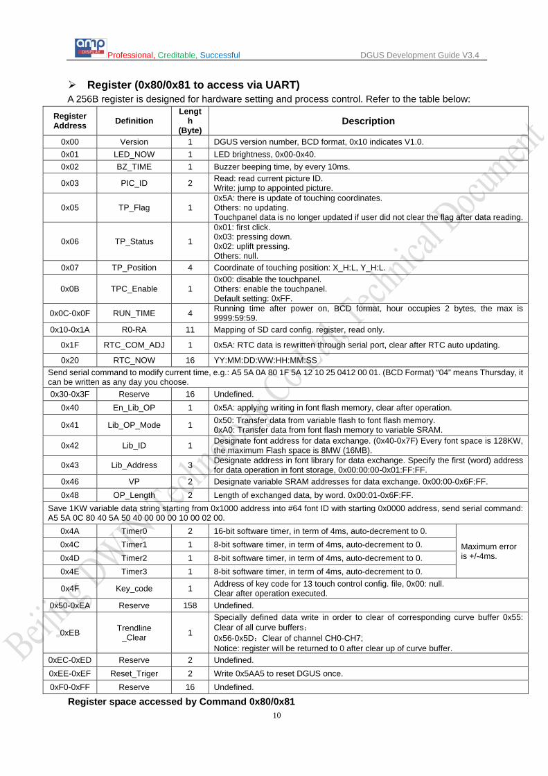
Register (0x80/0x81 to access via UART) A 256B register is designed for hardware setting and process control. Refer to the table below:
Register Address Definition
Length
(Byte) Description
0x00 Version 1 DGUS version number, BCD format, 0x10 indicates V1.0. 0x01 LED_NOW 1 LED brightness, 0x00-0x40. 0x02 BZ_TIME 1 Buzzer beeping time, by every 10ms.
0x03 PIC_ID 2 Read: read current picture ID. Write: jump to appointed picture.
0x05 TP_Flag 1 0x5A: there is update of touching coordinates. Others: no updating. Touchpanel data is no longer updated if user did not clear the flag after data reading.
0x06 TP_Status 1
0x01: first click. 0x03: pressing down. 0x02: uplift pressing. Others: null.
0x07 TP_Position 4 Coordinate of touching position: X_H:L, Y_H:L.
0x0B TPC_Enable 1 0x00: disable the touchpanel. Others: enable the touchpanel. Default setting: 0xFF.
0x0C-0x0F RUN_TIME 4 Running time after power on, BCD format, hour occupies 2 bytes, the max is 9999:59:59.
0x10-0x1A R0-RA 11 Mapping of SD card config. register, read only.
0x1F RTC_COM_ADJ 1 0x5A: RTC data is rewritten through serial port, clear after RTC auto updating.
0x20 RTC_NOW 16 YY:MM:DD:WW:HH:MM:SS Send serial command to modify current time, e.g.: A5 5A 0A 80 1F 5A 12 10 25 0412 00 01. (BCD Format) “04” means Thursday, it can be written as any day you choose. 0x30-0x3F Reserve 16 Undefined.
0x40 En_Lib_OP 1 0x5A: applying writing in font flash memory, clear after operation.
0x41 Lib_OP_Mode 1 0x50: Transfer data from variable flash to font flash memory. 0xA0: Transfer data from font flash memory to variable SRAM.
0x42 Lib_ID 1 Designate font address for data exchange. (0x40-0x7F) Every font space is 128KW, the maximum Flash space is 8MW (16MB).
0x43 Lib_Address 3 Designate address in font library for data exchange. Specify the first (word) address for data operation in font storage, 0x00:00:00-0x01:FF:FF.
0x46 VP 2 Designate variable SRAM addresses for data exchange. 0x00:00-0x6F:FF. 0x48 OP_Length 2 Length of exchanged data, by word. 0x00:01-0x6F:FF.
Save 1KW variable data string starting from 0x1000 address into #64 font ID with starting 0x0000 address, send serial command: A5 5A 0C 80 40 5A 50 40 00 00 00 10 00 02 00.
0x4A Timer0 2 16-bit software timer, in term of 4ms, auto-decrement to 0.
Maximum error is +/-4ms.
0x4C Timer1 1 8-bit software timer, in term of 4ms, auto-decrement to 0. 0x4D Timer2 1 8-bit software timer, in term of 4ms, auto-decrement to 0. 0x4E Timer3 1 8-bit software timer, in term of 4ms, auto-decrement to 0.
0x4F Key_code 1 Address of key code for 13 touch control config. file, 0x00: null. Clear after operation executed.
0x50-0xEA Reserve 158 Undefined.
0xEB Trendline _Clear 1
Specially defined data write in order to clear of corresponding curve buffer 0x55: Clear of all curve buffers; 0x56-0x5D:Clear of channel CH0-CH7; Notice: register will be returned to 0 after clear up of curve buffer.
0xEC-0xED Reserve 2 Undefined. 0xEE-0xEF Reset_Triger 2 Write 0x5AA5 to reset DGUS once. 0xF0-0xFF Reserve 16 Undefined.
Register space accessed by Command 0x80/0x81

Professional, Creditable, Successful DGUS Development Guide V3.4
11
Variable (0x82/0x83 to access via UART) 56KB variable SRAM can be used as extended RAM to save data for variables. Variable SRAM is divided into 28672 addresses from 0x0000 to 0x6FFF. Data in variable SRAM can be written by command 0x82 and read by command 0x83 Trend Curve Data Buffer The Trend curve data buffer is designed to store trend curve data. Data in trend curve buffer is written only by command 0x84. One word once at least. Data of each point is defined by a 2-byte unsigned integer. The Trend curve buffer will not occupy the variable SRAM. Maximum buffer for 8 trend curves can be updated simultaneously.
1.4 Firmware Upgrade
Method 1: via SD card. Upgrade your DGUS firmware by SD card is STRONGLY RECOMMENDED for V3.0 and higher firmware version. A.Copy the DGUS_V*.BIN into DWIN_SET in root directory of SD card. B.Insert SD card in the modules C.Screen will become blue and wait few seconds. The upgrade is complete.
Method 2: via serial port. Essential Facilities: DC regulated power supply. Serial port cable. A Computer which has a hardware serial port and serial debugging assistant SSCOM3.2 or similar software. Procedures of Upgrade: A. Power off DGUS module and connect module with PC via serial port. B. Open the SSCOM3.2 and click "Open File" to select a DGUS bin file, such as DGUS_V5.6.BIN. C. Write "DWIN_M600_BOOT!" in data input column and set send-eve interval to 10ms/Time. (see the following picture) D. Select "Send New" and "Send eve", then power DWIN module on again. E. The serial port will receive "Erase ......”. If no response, please check the connection. F. It will receive "Please Tx File!" after one second, then click "Send New" and click "Send File". G. Wait another 3 to 10 seconds. If the serial port receives "***************END***************", it
means the download is complete. H. Restart the module. The upgrade is complete.

Professional, Creditable, Successful DGUS Development Guide V3.4
12
Check Firmware Version: A. Connect DGUS HMI serial port with COM port on PC, B. Connect power. C.. Open the SSCOM3.2 and make sure that the "SendHEX" and "HexData" boxes are checked. D. Write the following command in the data input column: "Frame_Header (2 Bytes) 03 81 00 01",
press the “SEND” button. E.. Your computer will receive a feedback message like "Frame_Header (2 Bytes) 03 81 00 XX".
The last number XX is the version number in BCD format. e.g. 56= V5.6.(firmware version is V5.6)

Professional, Creditable, Successful DGUS Development Guide V3.4
13
1.5 Touch Screen Calibration
Method 1: quick click touch screen 20 times within 4 seconds in none-button area to activate calibration mode.
Quickly tap the touch screen more than 20 times in 4 seconds. Note: do not click button area. Click until a long beep emits from the buzzer. For the models without a buzzer, user can time for 4 seconds or judge by whether on not the variables are refreshed. Click area of touch screen to be calibrated. Calibration will finish and return to the starting page.
Method 2 (for V4.5 and higher version): Write “TP_CORRECT” in CONFIG.TXT in root directory of SD card to activate calibration made once. Caution-For V4.3 and higher versions, touch screen calibration will be disabled when SD card is disabled.
1.6 Enable/Disable SD Card Specific codes in CONFIG.TXT can be used to disable the SD card slot on the DGUS module with a password to avoid accidental operation. Code to Disable SD Card Description
Part 1 SD_LOCK Fixed. Part 2 1000 Password address in variable SRAM, 0x0000 – 0x6FF8. Part 3 ABCD1234 Password to re-enable SD card, 8 bytes.
Code in CONFIG.TXT to re-Enable SD card: SD_UNLOCK. E.g.: presume password is 12345678, saved in 0x6000 address in variable SRAM. Steps to disable SD card: 1. Write “SD_LOCK_6000_12345678” to CONFIG.TXT. 2. Copy CONFIG.TXT into DWIN_SET folder in SD card. 3. Plug SD card into slot on DGUS module to disable it. Steps to re-enable SD card: Method 1: Send password to module via serial port to activate SD card once. We take 0xA55A as frame header, send command: A5 5A 0B 82 60 00 31 32 33 34 35 36 37 38. Method 2: Using <Text Input> to type password can activate SD card once. Method 3: write re-able SD card command in CONFIG.TXT in root directory of SD card and plug SD card into slot on DGUS module to re-able SD card. WARNING- FAILURE TO INPUT CORRECT PASSWORD WILL RESULT IN SD CARD INTERFACE PERMANENT LOCKOUT! SAFEKEEP YOUR PASSWORD! Format your SD card: if part of your data in SD card is not downloaded into module, please format your SD card as the instruction below. Step 1: open RUN function in Windows and run DOS using “command”.

Professional, Creditable, Successful DGUS Development Guide V3.4
14
Not applicable for Mini DGUS.
Step 2: type command to format: “format/q g:/fs:fat32/a:4096”, and click <enter> to finish formatting. The letter in red is the disk number of SD card.
1.7 User program based on DWIN OS Backstage user program is supported by the DGUS module with the DWIN OS function. The user program, including maximum 32764 commands, is saved in address #23 in font flash memory. Specific codes in CONFIG.TXT can be used to disable/enable the user program. Enable user program: RUN_DWIN_OS. Disable user program: STOP_DWIN_OS. Executing cycle of the user program is the same with refresh cycle of variables (200ms or 250ms). Refer to <DWIN OS Development Guide> to get detailed information.

Professional, Creditable, Successful DGUS Development Guide V3.4
15
2 Serial Port Serial mode of DGUS module is asynchronous, full duplex serial port (UART). Each byte occupies 10 bits: 1 start bit, 8 data bits, and 1 stop bit. Baud rate can be defined by the SD card. All data transfer is in hexadecimal format with MSB priority. E.g.: transferring 0x1234, 0x12 will be transferred first, then 0x34 after. Busy pin is invalid for DGUS module; keep it unconnected. Volume of serial FIFO buffer is 4KB (around 230400-691200bps continuous send), minimum capacity of data transfer in DGUS circle (80/120/160/200ms). Maximum capacity depends on the complexity of GUI. Therefore, DWIN recommends sending no more than 4KB data to the DGUS module in a DGUS cycle.
2.1 Data Frame Data frame is made up by 4 parts, shown as below.
The maximum length of a data packet is 254 bytes (without CRC checksum) or 252 bytes (with CRC checksum). CRC checksum is only available for command and data, rather than data length and frame header, with ANSI CRC-16(X16+X15+X2+1) format.
Data 1 2 3 4 5
Definition Frame Header Data Length Command Data
CRC checksum of the
command and data
(optional)
Data Length 2 1 1 N 2
Description Defined by R3 & RA
in CONFIG.TXT
Data length, include
command, data and
checksum
0x80-0x84 Defined by R2 in
CONFIG.TXT
Different on Mini DGUS

Professional, Creditable, Successful DGUS Development Guide V3.4
16
2.2 Command Set (0x80-0x84) Function CMD Data Description
Access Register
0x80 ADR(0x00-0xFF)+Data_Pack Write data in designated addresses in register.
0x81 ADR(0x00-0xFF)+RD_LEN(0x00-0xFF) Read data in designated addresses in register. ADR(0x00-0xFF)+RD_LEN+Data_Pack Response of DGUS module.
Access Variable SRAM
0x82 ADR_H:L(0x0000-0x6FFF)+DATA0…DATAn Write data in designated addresses in variable SRAM.
0x83 ADR_H:L(0x0000-0x6FFF)+RD_LEN(0x00-0x7F)
Read data in designated addresses in variable SRAM.
ADR_H:L+RD_LEN+DATA0……DATAn Response of DGUS module.
Trend Curve Buffer
0x84 CH_Mode(Byte)+DATA0(Word)+…+DATAn
Write data in trend curve buffer. CH_Mode defines channels for trend curve channel of follow-up data order: Each bit of CH_Mode corresponds to one
channel; e.g.: CH_Mode .0 corresponds to channel 0, .7 corresponds to channel 7
1 in particular bit indicates the presence of the corresponding channel.
Data of lower channel is prior ranged. e.g.: CH_Mode = 0x83 (10000011B), indicates a follow-up data format : ( channel 0 + channel 1+ channel 7) +...+ (channel 0 + channel 1+ channel 7).
DGUS Register: 0x00H-0xFFH, is written / read by byte. DGUS Variable SRAM: 0x0000H-0x6FFFH, is written / read by word. Data in Curve buffer: is written / read by word. The communication between DGUS LCMs & Controllers (MCU) are driven by Variables that you may read and write in corresponding address. For further information, please refer Chapter 1.3 or Appendix 4: Command illustration.
3 Data Format To make it easier for calculation of MCUs, the data in DGUS module is in integer, unsigned integer, long integer and double long integer format. Integer: -32768 (0x8000) to +32767 (0x7FFF). Unsigned integer: 0 (0x0000) to 65535 (0xFFFF). Long integer: -2147483648 (0x80000000) to +2147483647 (0x7FFFFFFF). Double long integer: -9223372036854775808 to 9223372036854775807. Decimal numbers are represented by fix-point decimals. Example: 0x4D2(1234) indicates 12.34, if there are two decimal digits. The DGUS module uses the 16 bit color system.Refer to the chart below to view color palettedefinition.
65K-color Definition Bit 15 14 13 12 11 10 9 8 7 6 5 4 3 2 1 0
Define R4 R3 R2 R1 R0 G5 G4 G3 G2 G1 G0 B4 B3 B2 B1 B0 Red 0xF800 Green 0x07E0 Blue 0x001F

Professional, Creditable, Successful DGUS Development Guide V3.4
17
4 Touch Config. File (13.BIN) The Touch Config. File, which contains several touch commands, can be generated by DGUS_SDK. Each command occupies 16, 32 or 48 bytes and includes 6 parts.
Part Definition Data Length Description
1 Pic_ID 2 Picture ID
2 TP_Area 8 Touch button area: (Xs, Ys) (Xe, Ye). Xs=FFFF: the function of the button will be activated by key code in register 0xF4, set Ys_H as key code then disable press-down effect.
3 Pic_Next 2 Picture jump to. 0xFF**: disable picture switch.
4 Pic_On 2 Press-down effect. 0xFF**: disable press-down effect.
5 TP_Code 2
Touch key code: 0xFF**: Invalid key code. 0xFE**: Function buttons, e.g.: 0xFE00 indicates it’s a Variable Data Input button. 0x00**: Touch key code in ASCII format, e.g.: 0x0031 means “1”.
6 TP_FUN 16/32 When TP_Code = 0xFE**, parameters of functional buttons.
4.1 Variable Data Input (0x00)
Address Definition Data Length Description
0x00 Pic_ID 2 Picture ID. 0x02 TP_Area 8 Touch button area: (Xs, Ys) (Xe, Ye).
0x0A Pic_Next 2 Picture jump to. 0xFF**: disable picture switch.
0x0C Pic_On 2 Press-down effect. 0xFF**: disable press-down effect.
0x0E TP_Code 2 0xFE00 0x10 0xFE 1 0xFE 0x11 *VP 2 Variable pointer.
0x13 V_Type 1
Inputted variables format. 0x00: integer (word). 0x01: long integer (double word). 0x02: unsigned byte (high byte of VP address). 0x03: unsigned byte (low byte of VP address). 0x04: double long integer, -9223372036854775808 to 9223372036854775807.
0x14 N_Int 1 Integer digits, e.g.: input 1234.56, so N_Int = 0x04. 0x15 N_Dot 1 Decimal digits, e.g.: input 1234.56, so N_Dot = 0x02. 0x16 (x,y) 4 Position of cursor, right alignment. 0x1A Color 2 Font color. 0x1C Lib_ID 1 Address of ASCII Font file, 0x00: default #0 ASCII font. 0x1D Font_Hor 1 Font size, by pixel numbers in X-direction.
0x1E Cursor_Color 1 Cursor color. 0x00: black, others: white.
0x1F Hide_En 1 0x00: encrypted display, others: unencrypted display. 0x20 0xFE 1 0xFE
0x21 KB_Source 1 0x00: call keypad from current page. Others: call keypad from designated page.
0x22 PIC_KB 2 Picture ID of keypad. Null if KB_Source = 0x00.
0x24 AREA_KB 8 Cut area for keypad (Xs, Ys) (Xe, Ye). Null if KB_Source = 0x00.
0x2C AREA_KB_Position 4 Paste position of keypad on current page. Null if KB_Source = 0x00.
0x30 0xFE 1 0xFE
0x31 Limits_En 1 0xFF: enable range limit of inputting value, null if over range. Others: disable range limit.
0x32 V_min 4 Floor of range (long integer, 4 bytes).

Professional, Creditable, Successful DGUS Development Guide V3.4
18
0x36 V_max 4 Ceiling of range (long integer, 4 bytes). 0x3A Reserve 6 0x00 fixed.
Valid key codes: 0x0030 – 0x0039 (Number 0 - 9), 0x002E (.), 0x002D (+/-), 0x00F0 (cancel), 0x00F1 (confirm),
0x00F2 (backspace).
Call keypad from current page (KB_Source = 0x00).
Call keypad from designated page (KB_Source = 0x01): keypad is activated after click.
Call keypad from designated page (KB_Source = 0x01): page with keypad.

Professional, Creditable, Successful DGUS Development Guide V3.4
19
4.2 Popup Window (0x01)
Address Definition Data Length Description
0x00 Pic_ID 2 Picture ID.
0x02 TP_Area 8 Touch button area: (Xs, Ys) (Xe, Ye).
0x0A Pic_Next 2 Picture jump to. 0xFF**: disable picture switch.
0x0C Pic_On 2 Press-down effect. 0xFF**: disable press-down effect.
0x0E TP_Code 2 0xFE01
0x10 0xFE 1 0xFE
0x11 *VP 2 Variable pointer.
0x13 VP_Mode 1
Key code format. 0x00: write key code in VP address (word). 0x01: write low byte of key code in high byte of VP. 0x02: write low byte of key code in low byte of VP. 0x10-0x1F: write data from last bit of key code into designated bit of VP address. (0x10 corresponds to VP.0, 0x1F corresponds to VP.F)
0x14 Pic_Menu 2 Picture ID of popup window.
0x16 AREA_Menu 8 Cut area for popup window: (Xs, Ys) (Xe, Ye).
0x1E Menu_Position_X 2 Paste position of popup window: X coordinate.
0x20 0xFE 1 0xFE
0x21 Menu_Position_Y 2 Paste position of popup window: Y coordinate.
0x23 NULL 13 0x00 fixed.
Valid key code: 0x0000 – 0x00FF, 0xFF: cancel.
Key code (0x0000 – 0x00FE) of “Start” and “End” button will be written in VP address. Designate 0x00FF key code for “Esc” button. By the way, drop-down menu also could be designed by this command.

Professional, Creditable, Successful DGUS Development Guide V3.4
20
4.3 Incremental Adjustment (0x02) Address Definition Data
Length Description
0x00 Pic_ID 2 Picture ID.
0x02 TP_Area 8 Touch button area: (Xs, Ys) (Xe, Ye).
0x0A Pic_Next 2 0xFF**.
0x0C Pic_On 2 Press-down effect. 0xFF**: disable press-down effect.
0x0E TP_Code 2 0xFE02
0x10 0xFE 1 0xFE
0x11 *VP 2 Variable pointer.
0x13 VP_Mode 1
Adjust value mode. 0x00: adjust value in VP address (integer). 0x01: adjust value in high byte of VP address (unsigned byte). 0x02: adjust value in low byte of VP address (un signed byte). 0x10-0x1F: adjust value in designated bit of VP address. (0x10 corresponds to VP.0, 0x1F corresponds to VP.F) Step size must be 0 or 1.
0x14 Adj_Mode 1 Adjust mode. 0x00: --, others: ++.
0x15 Return_Mode 1 Loop. 0x00: disable loop, others: enable loop.
0x16 Adj_Step 2 Step size: 0x0000-0x7FFF.
0x18 V_Min 2 Floor of range (integer), low byte is valid when VP_Mode is 0x01 or 0x02.
0x1A V_Max 2 Ceiling of range (integer), low byte is valid when VP_Mode is 0x01 or 0x02.
0x1C Key_Mode 1 0x00: continuous press to adjust successively 0x01: one-step adjust as pressing
0x1D NULL 3 0x00 fixed.
Set two buttons for “+” (Adj_Mode=0x01) and “–“ (Adj_Mode=0x00). Set range as 0 – 1, and match up with function Variable Icon, check function will be achieved. (Press once to pick up and twice to cancel.)

Professional, Creditable, Successful DGUS Development Guide V3.4
21
4.4 Slider Adjustment (0x03) Address Definition Data
Length Description
0x00 Pic_ID 2 Picture ID.
0x02 TP_Area 8 Touch button area: (Xs, Ys) (Xe, Ye).
0x0A Pic_Next 2 0xFF**
0x0C Pic_On 2 0xFF**
0x0E TP_Code 2 0xFE03
0x10 0xFE 1 0xFE
0x11 *VP 2 Variable pointer.
0x13 Adj_Mode 1
First 4 bits define data format. 0x0*: adjust value in VP address (integer). 0x1*: adjust value in high byte of VP (unsigned byte). 0x2*: adjust value in low byte of VP (unsigned byte). Last 4 bits define sliding mode. 0x*0: horizontal. 0x*1: vertical.
0x14 Area_Adj 8 Effective sliding area (Xs, Ys) (Xe, Ye), should equal to value of TP_Area.
0x1C V_begin 2 Start return value (integer).
0x1E V_end 2 End return value (integer).
Slider is activated after holding for 0.5 second to avoid mis-operation.
Slider function is applied to indicate current volume (refer to Chapter 5.1.3). Values can also be indicated by <Data Variable> function to have current value (refer to Chapter 5.2.1). Slider Adjustment does not support machine buttons (key code in register 0X4F).

Professional, Creditable, Successful DGUS Development Guide V3.4
22
4.5 The RTC Settings (0x04)
Address Definition Data Length Description
0x00 Pic_ID 2 Picture ID. 0x02 TP_Area 8 Touch button area: (Xs, Ys) (Xe, Ye).
0x0A Pic_Next 2 Picture jump to. 0xFF**: disable picture switch.
0x0C Pic_On 2 Press-down effect. 0xFF**: disable press-down effect.
0x0E TP_Code 2 0xFE04 0x10 0xFE 1 0xFE 0x11 0x00 00 00 3 0x00 00 00 fixed. 0x14 (x, y) 4 Position of cursor, right alignment. 0x18 Color 2 Font color. 0x1A Lib_ID 1 Address of font file. 0x1B Font_Hor 1 Font size, by pixel numbers in X-direction.
0x1C Cursor_Color 1 Cursor color. 0x00: black, others: white.
0x1D KB_Source 1 0x00: call keypad from current page. Others: call keypad from designated page.
0x1E PIC_KB 2 Picture ID of keypad. Null if KB_Source = 0x00.
0x20 0xFE 1 0xFE
0x21 AREA_KB 8 Cut area for keypad (Xs, Ys) (Xe, Ye). Null if KB_Source = 0x00.
0x29 AREA_KB_Position 4 Paste position of keypad on current page. Null if KB_Source = 0x00.
0x2D NULL 3 0x00 fixed.
Parameters are the same with function <Variable Input>.

Professional, Creditable, Successful DGUS Development Guide V3.4
23
4.6 Return Key Code (0x05)
Address Definition Data Length Description
0x00 Pic_ID 2 Picture ID.
0x02 TP_Area 8 Touch button area: (Xs, Ys) (Xe, Ye).
0x0A Pic_Next 2 Picture jump to. 0xFF**: disable picture switch.
0x0C Pic_On 2 Press-down effect. 0xFF**: disable press-down effect.
0x0E TP_Code 2 0xFE05 0x10 0xFE 1 0xFE 0x11 *VP 2 Variable pointer.
0x13 VP_Mode 1
Adjust value mode. 0x00: adjust value in VP address (integer). 0x01: adjust value in high byte of VP address (integer). 0x02: adjust value in low byte of VP address (integer). 0x10-0x1F: write data from last bit of key code into designated bit of VP address. (0x10 corresponds to VP.0, 0x1F corresponds to VP.F)
0x14 Key_Code 2 Return key code.
0x16 NULL 10 0x00 fixed.
4.7 Text Input (0x06)
Address Definition Data Length Description
0x00 Pic_ID 2 Picture ID.
0x02 TP_Area 8 Touch button area: (Xs, Ys) (Xe, Ye).
0x0A Pic_Next 2 Picture jump to. 0xFF**: disable picture switch.
0x0C Pic_On 2 Press-down effect. 0xFF**: disable press-down effect.
0x0E TP_Code 2 0xFE06
0x10 0xFE 1 0xFE
0x11 *VP 2 Variable pointer.
0x13 VP_Len_Max 1 Max length of text, by word (0x01-0x7B). 0xFFFF as end mark will be added at the end of text. Max address number of text should be VP_Len_Max + 1
0x14 Scan_Mode 1 Input mode. 0x00: re-input, 0x01: modify existing text.
0x15 Lib_ID 1 Address of font file.
0x16 Font_Hor 1 Font size, by pixel numbers in X-direction.
0x17 Font_Ver 1 Font size, by pixel numbers in Y-direction. Should be 2 times of pixels in X-direction if Lib_ID = 0x00.
0x18 Cursor_Color 1 Cursor color. 0x00: black, others: white.
0x19 Color 2 Text color. 0x1B Scan_Area_Start 4 Top-left coordinates of text (Xs, Ys).
0x1F Scan_Return_Mode 1
0x55: save input terminator and valid data length at (VP-1) position. High byte in (VP-1) for input terminator: 0x5A indicates input is finished, other value shows input is in-process. Low byte in (VP-1) data length for valid input, counted in bytes. 0x00: disable input status return.
0x20 0xFE 1 0xFE 0x21 Scan_Area_End 4 Bottom-right coordinates of text (Xe, Ye).
0x25 KB_Source 1 0x00: call keypad from current page. Others: call keypad from designated page.

Professional, Creditable, Successful DGUS Development Guide V3.4
24
0x26 PIC_KB 2 Picture ID of keypad. Null if KB_Source = 0x00.
0x28 AREA_KB 8 Cut area for keypad (Xs, Ys) (Xe, Ye). Null if KB_Source = 0x00.
0x30 0xFE 1 0xFE
0x31 AREA_KB_Position 4 Paste position of keypad on current page. Null if KB_Source = 0x00.
0x35 DISPLAY_EN 1 0x00: unencrypted display, 0x01: encrypted display. 0x36 NULL 10 0x00 fixed
Note: the pre-loaded #0 font includes all the ASCII codes in the following pixels, 4*8 to 64*128. Key code table for text input Key code consists of 2 bytes. Low byte indicates lower-case letters, while high byte indicates capital letters. Refer to the table below to see key code table. All key codes follow ASCII table.
Key Ordinary Capital Key Ordinary Capital Key Ordinary Capital Key Ordinary Capital 0x7E60 ` ~ 0x5171 q Q 0x4161 a A 0x5A7A z Z 0x2131 1 ! 0x5777 w W 0x5373 s S 0x5878 x X 0x4032 2 @ 0x4565 e E 0x4464 d D 0x4363 c C 0x2333 3 # 0x5272 r R 0x4666 f F 0x5676 v V 0x2434 4 $ 0x5474 t T 0x4767 g G 0x4262 b B 0x2535 5 % 0x5979 y Y 0x4868 h H 0x4E6E n N 0x5E36 6 ^ 0x5575 u U 0x4A6A j J 0x4D6D m M 0x2637 7 & 0x4969 i I 0x4B6B k K 0x3C2C , < 0x2A38 8 * 0x4F6F o O 0x4C6C l L 0x3E2E . > 0x2839 9 ( 0x5070 p P 0x3A3B ; : 0x3F2F / ? 0x2930 0 ) 0x7B5B [ { 0x2227 ' " 0x2020 SP SP 0x5F2D - _ 0x7D5D ] } 0x0D0D Enter Enter 0x2B3D = + 0x7C5C \ | Note: The key code of text input should be less than 0x80 (ASCII code). Key code “0x0D” will be automatically
transferred into 0x0D 0x0A. Key code 0x00 and 0xFF: null.
Function keys Key Definition Description
0x00F0 Cancel Cancel the operation, no affect to variable data. 0x00F1 Return Save the input text to the designated address and return. 0x00F2 Backspace Backspace, delete one character. 0x00F3 Delete Delete. 0x00F4 CapsLock Caps lock. Must assign the button effect to enable it. 0x00F7 Left Cursor forwards for one character. 0x00F8 Right Cursor backwards for one character.

Professional, Creditable, Successful DGUS Development Guide V3.4
25
Note: when users prefer to keyboard(key value in 0x4F) for text input, if CapsLock needed, please set animation
area of button on the area where CapsLock input to be reminded. Only in this way, CapsLock reminder will show
up on the area.
Professional, Creditable, Successful DGUS Development Guide V3.4
26
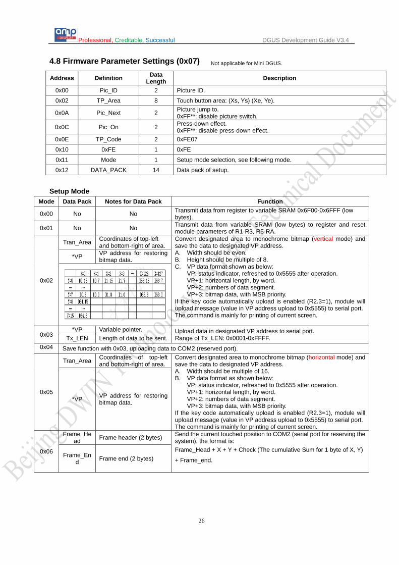
Not applicable for Mini DGUS. 4.8 Firmware Parameter Settings (0x07)
Address Definition Data Length Description
0x00 Pic_ID 2 Picture ID.
0x02 TP_Area 8 Touch button area: (Xs, Ys) (Xe, Ye).
0x0A Pic_Next 2 Picture jump to. 0xFF**: disable picture switch.
0x0C Pic_On 2 Press-down effect. 0xFF**: disable press-down effect.
0x0E TP_Code 2 0xFE07
0x10 0xFE 1 0xFE
0x11 Mode 1 Setup mode selection, see following mode.
0x12 DATA_PACK 14 Data pack of setup.
Setup Mode
Mode Data Pack Notes for Data Pack Function
0x00 No No Transmit data from register to variable SRAM 0x6F00-0x6FFF (low bytes).
0x01 No No Transmit data from variable SRAM (low bytes) to register and reset module parameters of R1-R3, R5-RA.
0x02
Tran_Area Coordinates of top-left and bottom-right of area.
Convert designated area to monochrome bitmap (vertical mode) and save the data to designated VP address. A. Width should be even. B. Height should be multiple of 8. C. VP data format shown as below:
VP: status indicator, refreshed to 0x5555 after operation. VP+1: horizontal length, by word. VP+2: numbers of data segment. VP+3: bitmap data, with MSB priority.
If the key code automatically upload is enabled (R2.3=1), module will upload message (value in VP address upload to 0x5555) to serial port. The command is mainly for printing of current screen.
*VP VP address for restoring bitmap data.
0x03 *VP Variable pointer. Upload data in designated VP address to serial port.
Range of Tx_LEN: 0x0001-0xFFFF. Tx_LEN Length of data to be sent. 0x04 Save function with 0x03, uploading data to COM2 (reserved port).
0x05
Tran_Area Coordinates of top-left and bottom-right of area.
Convert designated area to monochrome bitmap (horizontal mode) and save the data to designated VP address. A. Width should be multiple of 16. B. VP data format as shown below:
VP: status indicator, refreshed to 0x5555 after operation. VP+1: horizontal length, by word. VP+2: numbers of data segment. VP+3: bitmap data, with MSB priority.
If the key code automatically upload is enabled (R2.3=1), module will upload message (value in VP address upload to 0x5555) to serial port. The command is mainly for printing of current screen.
*VP VP address for restoring bitmap data.
0x06
Frame_Head Frame header (2 bytes) Send the current touched position to COM2 (serial port for reserving the
system), the format is: Frame_Head + X + Y + Check (The cumulative Sum for 1 byte of X, Y)
+ Frame_end.
Frame_End Frame end (2 bytes)

Professional, Creditable, Successful DGUS Development Guide V3.4
27
5 Variable Config. File (14.BIN) The Variable Config. file, containing several variable commands, can be generated by DGUS_SDK. Since each command occupies 32 bytes and each page contains 64 variable commands, space for each page is 2KB (0x0800). Max page number is 1024, and max volume of variable Config. file is 2MB. Priority of display is last in-first out (LIFO). Variable command contains 6 sections.
No. Definition Data Length Description
1 0x5A 1 Fixed
2 Type 1 Variable type.
3 *SP 2 Stack pointer, default setting is 0xFFFF (set by Config. file).
4 Len_Dsc 2 The whole process length (in terms of words).
5 *VP 2 Variable pointer, 0x0000-0x6FFF. Write 0x0000 for the variables that do not need address assigning. The command will be disabled when the high byte is 0xFF.
6 Description N Parameters of variable.
5.1 Variable Icon 5.1.1 Variable Icon (0x00)
Address Definition Data Length Description
0x00 0x5A00 2
0x02 *SP 2 Stack pointer, default setting is 0xFFFF (set by Config. file).
0x04 0x0008 2 The whole process length (in terms of words).
0x06 0x00 *VP 2 Variable pointer.
0x08 0x01 (x, y) 4 Display position, top-left coordinate of icon.
0x0C 0x03 V_Min 2 Floor of range, null if over range.
0x0E 0x04 V_Max 2 Ceiling of range, null if over range.
0x10 0x05 Icon_Min 2 Icon address in icon file corresponding to min value.
0x12 0x06 Icon_Max 2 Icon address in icon file corresponding to max value.
0x14 0x07:H Icon_Lib 1 Address of icon file.
0x15 0x07:L Mode 1 Icon display mode. 0x00: transparent. Others: opaque.

Professional, Creditable, Successful DGUS Development Guide V3.4
28
5.1.2 Animation Icon (0x01) Address Definition Data
Length Description
0x00 0x5A01 2 0x02 *SP 2 Stack pointer, default setting is 0xFFFF (set by Config. file). 0x04 0x000A 2 The whole process length (in terms of words).
0x06 0x00 *VP 2 Variable pointer of initial icon. High word: unsigned integer. Low word: reserved, status of animation. (0x0000-0x0FFFF)
0x08 0x01 (x, y) 4 Display position, top-left coordinate of icon. 0x0C 0x03 0x0000 2 0x0000 fixed. 0x0E 0x04 V_Stop 2 Value corresponding to stop animation. 0x10 0x05 V_Start 2 Value corresponding to start animation. 0x12 0x06 Icon_Stop 2 Icon at V_Stop value. 0x14 0x07 Icon_Start 2
Start/end icons for animation at V_Start value. 0x16 0x08 Icon_End 2
0x18 0x09:H Icon_Lib 1 Address of icon file.
0x19 0x09:L Mode 1 Icon display mode. 0x00: transparent. Others: opaque.
If the value in VP address is equal to neither V_Stop nor V_Start, icons are not displayed on screen

Professional, Creditable, Successful DGUS Development Guide V3.4
29
5.1.3 Slider (0x02) Address Definition Data
Length Description
0x00 0x5A02 2
0x02 *SP 2 Stack pointer, default setting is 0xFFFF (set by Config. file).
0x04 0x0009 2 The whole process length (in terms of words).
0x06 0x00 *VP 2 Variable pointer.
0x08 0x01 V_begin 2 Variable corresponding to start point.
0x0A 0x02 V_end 2 Variable corresponding to end point.
0x0C 0x03 X_begin 2 Starting position of slider. X coordinates for horizontal sliders. (Y coordinates for vertical sliders.)
0x0E 0x04 X_end 2 Ending position of slider. X coordinates for horizontal sliders. (Y coordinates for vertical sliders.)
0x10 0x05 Icon_ID 2 Icon address in icon file.
0x12 0x06 Y 2 Position of slider. Y coordinates for vertical sliders. (X coordinates for horizontal sliders.)
0x14 0x07:H X_adj 1 X/Y axis offset to the left/top.
0x15 0x07:L Mode 1 Slider mode. 0x00: horizontal, others: vertical.
0x16 0x08:H Icon_Lib 1 Address of icon file.
0x17 0x08:L Icon_mode 1 Icon display mode. 0x00: transparent, others: opaque.
0x18 0x09:H VP_DATA_Mode 1 0x00: integer (whole VP address). 0x01: high byte in VP address. 0x02: low byte in VP address.

Professional, Creditable, Successful DGUS Development Guide V3.4
30
5.1.4 WordArt (0x03) Address Definition Data
Length Description
0x00 0x5A03 2
0x02 *SP 2 Stack pointer, default setting is 0xFFFF (set by Config. file).
0x04 0x0007 2 The whole process length (in terms of words).
0x06 0x00 *VP 2 Variable pointer.
0x08 0x01 X, Y 4 Top-left coordinate of words, left aligned or top-right coordinate of words, right aligned.
0x0C 0x03 Icon0 2 Icon corresponding to number 0, by sequence of “01234567890-.”.
0x0E 0x04:H Icon_Lib 1 Address of icon file.
0x0F 0x04:L Icon_Mode 1 Icon display mode. 0x00: transparent, others: opaque.
0x10 0x05:H Int_Num 1 Length of integer digits.
0x11 0x05:L Dec_Num 1 Length of decimal digits.
0x12 0x06:H VP_Data_Mode 1
0x00: integer (2 bytes), from -23768 to 32767 0x01: long integer (4 bytes), from -2147483648 to 2147483647 0x02: *VP high byte, no unsigned, from 0 to 255 0x03: *VP low byte, no unsigned, from 0 to 255 0x04: ultra-long integer(8 bytes), from -9223372036854775808 to 9223372036854775807 0x05: unsigned integer(2 bytes), from 0 to 65535 0x06: unsigned long integer(4 bytes), from 0 to 4294967295
0x13 0x06:L ALI 1 0x00: left-aligned, 0x01: right-aligned.
Professional, Creditable, Successful DGUS Development Guide V3.4
31
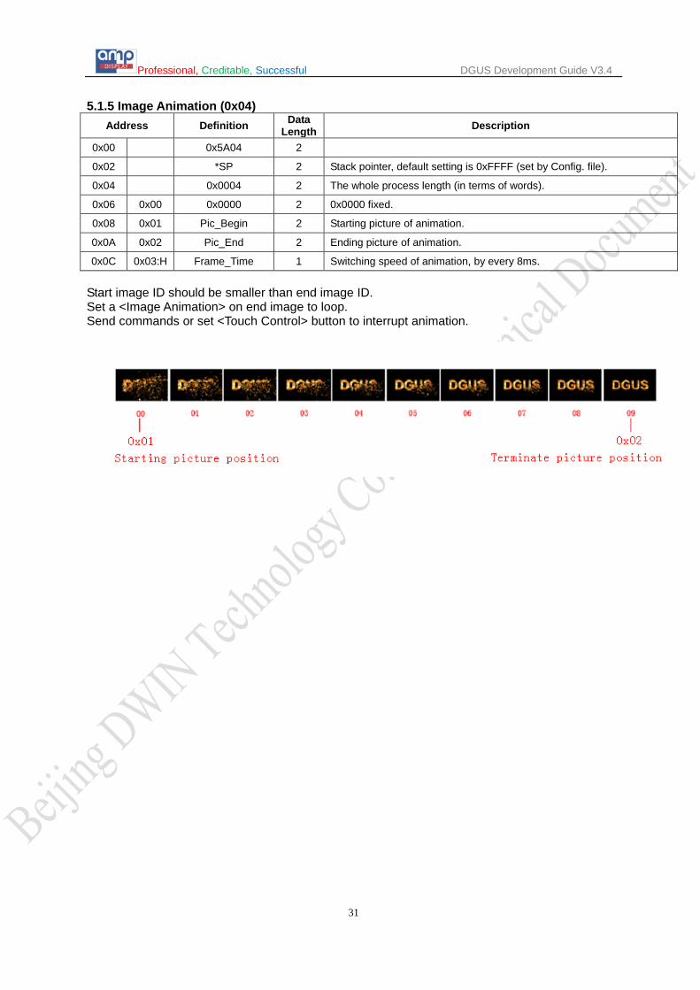
5.1.5 Image Animation (0x04) Address Definition Data
Length Description
0x00 0x5A04 2
0x02 *SP 2 Stack pointer, default setting is 0xFFFF (set by Config. file).
0x04 0x0004 2 The whole process length (in terms of words).
0x06 0x00 0x0000 2 0x0000 fixed.
0x08 0x01 Pic_Begin 2 Starting picture of animation.
0x0A 0x02 Pic_End 2 Ending picture of animation.
0x0C 0x03:H Frame_Time 1 Switching speed of animation, by every 8ms.
Start image ID should be smaller than end image ID. Set a <Image Animation> on end image to loop. Send commands or set <Touch Control> button to interrupt animation.

Professional, Creditable, Successful DGUS Development Guide V3.4
32
5.1.6 Icon Rotation (0x05) Address Definition Data
Length Description
0x00 0x5A05 2
0x02 *SP 2 Stack pointer, default setting is 0xFFFF (set by Config. file).
0x04 0x000C 2 The whole process length (in terms of words).
0x06 0x00 *VP 2 Variable pointer.
0x08 0x01 Icon_ID 2 Icon address in icon file.
0x0A 0x02 Icon_Xc 2 Rotation center of icon: X coordinate.
0x0C 0x03 Icon_Yc 2 Rotation center of icon: Y coordinate.
0x0E 0x04 Xc 2 Rotation center on current screen: X coordinate.
0x10 0x05 Yc 2 Rotation center on current screen: Y coordinate.
0x12 0x06 V_Begin 2 Value corresponding to starting angle, null if over range.
0x14 0x07 V_End 2 Value corresponding to ending angle, null if over range.
0x16 0x08 AL_Begin 2 Starting angle, range from 0 to 720 (0x000 - 0x2D0), by every 0.5°.
0x18 0x09 AL_End 2 Ending angle, range from 0 to 720 (0x000 - 0x2D0), by every 0.5°.
0x1A 0x0A:H VP_Mode 1
VP mode. 0x00: integer (whole VP address). 0x01: high byte in VP address. 0x02: low byte in VP address.
0x1B 0x0A:L Lib_ID 1 Address of icon file.
0x1C 0x0B Mode 1 Icon display mode. 0x00: transparent, others: opaque.
This function is mainly used for dash board. Rotation is always clockwise, AL_Begin should be larger than AL_End, (or a 360 will be added to AL_End by system).

Professional, Creditable, Successful DGUS Development Guide V3.4
33
5.1.7 Bit Variable Icon (0x06) Address Definition Data
Length Description
0x00 0x5A06 2
0x02 *SP 2 Stack pointer, default setting is 0xFFFF (set by Config. file).
0x04 0x000C 2 The whole process length (in terms of words).
0x06 0x00 *VP 2 Variable pointer, by word.
0x08 0x01 *VP_AUX 2 Substitutive variable pointer, reserved 2 words. User software unable to access.
0x0A 0x02 Act_Bit_Set 2 Display is on when bit value of VP is 1.
0x0C 0x03:H Display_Mode 1
Display_Mode Bit Value 0 1
0x00 ICON0S ICON1S
0x01 ICON0S Null.
0x02 ICON0S Animation: ICON1S-ICON1E.
0x03 Null. ICON1S
0x04 Null. Animation: ICON1S-ICON1E.
0x05 Animation: ICON0S-ICON0E. ICON1S
0x06 Animation: ICON0S-ICON0E. Null.
0x07 Animation: ICON0S-ICON0E.
Animation: ICON1S-ICON1E.
0x0D 0x03:L Move_Mode 1
Bit icons arranged mode. 0x00: X++, space unreserved for undesignated bits. 0x01: Y++, space unreserved for undesignated bits. 0x02: X++, space reserved for undesignated bits. 0x03: Y++, space reserved for undesignated bits.
0x0E 0X04:H Icon_Mode 1 Icon display mode.
0x00: transparent, 0x01: opaque. 0x0F 0x04:L Icon_Lib 1 Address of icon file.
0x10 0x05 ICON0S 2 Icon ID for bit0 in non-animation mode, or starting icon ID for bit0 in animation mode.
0x12 0x06 ICON0E 2 Ending icon ID for bit0 in animation mode.
0x14 0x07 ICON1S 2 Icon ID for bit1 in non-animation mode, or starting icon ID for bit1 in animation mode.
0x16 0x08 ICON1E 2 Ending icon ID for bit1 in animation mode.
0x18 0x09 X, Y 4 Top-left coordinates of starting icons.
0x1C 0x0B DIS_MOV 2 Spacing between icons.
0x1E 0x00 fixed
Professional, Creditable, Successful DGUS Development Guide V3.4
34
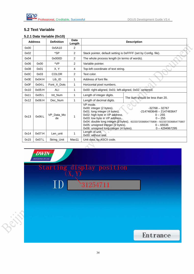
5.2 Text Variable 5.2.1 Data Variable (0x10)
Address Definition Data Length Description
0x00 0x5A10 2
0x02 *SP 2 Stack pointer, default setting is 0xFFFF (set by Config. file).
0x04 0x000D 2 The whole process length (in terms of words).
0x06 0x00 *VP 2 Variable pointer.
0x08 0x01 X, Y 4 Top-left coordinate of text string.
0x0C 0x03 COLOR 2 Text color.
0x0E 0x04:H Lib_ID 1 Address of font file.
0x0F 0x04:L Font_X_Dots 1 Horizontal pixel numbers.
0x10 0x05:H ALI 1 0x00: right-aligned, 0x01: left-aligned, 0x02: centered.
0x11 0x05:L Int_Num 1 Length of integer digits. The sum should be less than 20.
0x12 0x06:H Dec_Num 1 Length of decimal digits.
0x13 0x06:L VP_Data_Mode 1
VP mode. 0x00: integer (2 bytes). -32768 – 32767 0x01: long integer (4 bytes). -2147483648 – 2147483647 0x02: high byte in VP address. 0 – 255 0x03: low byte in VP address. 0 – 255 0x04: double long integer (8 bytes). -9223372036854775808 – 9223372036854775807 0x05: unsigned integer (2 bytes). 0 – 65535 0x06: unsigned long integer (4 bytes). 0 – 4294967295
0x14 0x07:H Len_unit 1 Length of unit. 0x00: without unit.
0x15 0x07:L String_Unit Max11 Unit data, by ASCII code.

Professional, Creditable, Successful DGUS Development Guide V3.4
35
5.2.2 Text (0x11) Address Definition Data
Length Description
0x00 0x5A11 2
0x02 *SP 2 Stack pointer, default setting is 0xFFFF (set by Config. file).
0x04 0x000D 2 The whole process length (in terms of words).
0x06 0x00 *VP 2 Variable pointer.
0x08 0x01 X, Y 4 Top-left coordinate of text string.
0x0C 0x03 Color 2 Text color.
0x0E 0x04 Xs Ys Xe Ye 8 Scope of text box, top-left and bottom-right coordinates.
0x16 0x08 Text_length 2 Text length, by byte. Data will not display if it is changed into 0xFFFF or over range.
0x18 0x09:H Font0_ID 1 Address of font file for encoding mode 0x01 - 0x04.
0x19 0x09:L Font1_ID 1 Address of font file for encoding mode 0x00 and 0x05, also other non-ASCII font for encoding mode 0x01 - 0x04.
0x1A 0x0A:H Font_X_Dots 1 Font size in X-direction. X should be Y/2 for encoding mode 0x01-0x04.
0x1B 0x0A:L Font_Y_Dots 1 Font size in Y-direction. Must be even.
0x1C 0x0B:H Encode_Mode 1
Spacing between letters is defined by .7 bit. .7 = 0: adapted spacing automatically. .7 = 1: fixed spacing. Encoding mode is defined by .6 to .0 bit. 0: 8 bit coding, 1: GB2312, 2: GBK, 3:BIG5, 4: SJIS, 5: UNICODE.
0x1D 0x0B:L HOR_Dis 1 Character spacing.
0x1E 0x0C:H VER_Dis 1 Line spacing.
0x1F 0x0C:L 0x00 fixed
Dots number in Y-direction must be even.
All ASCII characters from 4*8 pixels to 64*128 pixels are included in 0_DWIN_ASCII.hzk.

Professional, Creditable, Successful DGUS Development Guide V3.4
36
5.2.3 RTC (0x12) Digital RTC
Address Definition Data Length Description
0x00 0x5A12 2
0x02 *SP 2 Stack pointer, default setting is 0xFFFF (set by Config. file).
0x04 0x000D 2 The whole process length (in terms of words).
0x06 0x00 0x0000 2 0x0000 fixed.
0x08 0x01 X, Y 4 Top-left coordinates of text.
0x0C 0x03 Color 2 Text color.
0x0E 0x04:H Lib_ID 1 Address of ASCII font file.
0x0F 0x04:L Font_X_Dots 1 Font size in X-direction.
0x10 0x05 String_Code MAX16
Character string, by the RTC code table and ASCII code. E.g.: current time is 2012-05-02 12:00:00 Wednesday, Y-M-D H: Q: S 0x00, will be displayed as “2012-05-02 12:00:00”. M-D W H: Q 0x00, will be displayed as “05-02 WED 12:00”.
RTC Code table Description Encoding Format
Year Y 2000-2099 Month M 01-12 Day D 01-31 Hour H 00-23
Minute Q 00-59 Second S 00-59
Date W SUN MON TUE WED THU FRI SAT Coding end 0x00
Analog Clock Address Definition Data
Length Description
0x00 0x5A12 2 0x02 *SP 2 Stack pointer, default setting is 0xFFFF (set by Config. file). 0x04 0x000D 2 The whole process length (in terms of words). 0x06 0x00 0x0001 2 0x0001 0x08 0x01 X, Y 4 Rotation center of analog clock on current screen. 0x0C 0x03 Icon_Hour 2 Hour hand icon address in icon file, 0xFFFF: null. 0x0E 0x04 Icon_Hour_Central 4 Rotation center of hour hand icon. 0x12 0x06 Icon_Minute 2 Minute hand icon address in icon file, 0xFFFF:null. 0x14 0x07 Icon_Minute_Central 4 Rotation center of minute hand icon. 0x18 0x09 Icon_Second 2 Second hand icon address in icon file, 0xFFFF: null. 0x1A 0x0A Icon_Second_Central 4 Rotation center of second hand icon. 0x1E 0x0C:H ICON_Lib 1 Address of icon file. 0x1F 1 0x00.

Professional, Creditable, Successful DGUS Development Guide V3.4
37
5.2.4 Timer Variable (0x13)
Address Definition Data Length Description
0x00 0x5A13 2 0x02 *SP 2 Stack pointer, default setting is 0xFFFF (set by Config. file). 0x04 0x000D 2 The whole process length (in terms of words).
0x06 0x00 *VP 2
Starting variable pointer of data string, data is encoded with BCD format. The data will be displayed in HEX format when half-byte data is greater than 0x9, e.g.: 0x32: 32, 0xBF: BF.
0x08 0x01 X, Y 4 Top-left coordinate of text. 0x0C 0x03 Color 2 Text color. 0x0E 0x04:H Byte_Num 1 Byte numbers to be displayed, 0x01 - 0x0F.
0x0F 0x04:L Lib_ID 1 Address of font file. The format of font must be 8bit encoding, half-width, if Lib_ID is not 0x00.
0x10 0x05:H Font_X 1 Font size in X-direction.
0x11 0x05:L String_Code MAX15
Encoded separators string, used to define the format of Timer. Every time a Timer data (BCD code) is read, one ASCII char will be added after as separator. Some special chars: 0x00: none, Timer data will be concatenated; 0x0D: new line.
Professional, Creditable, Successful DGUS Development Guide V3.4
38
Different between DGUS and Mini DGUS
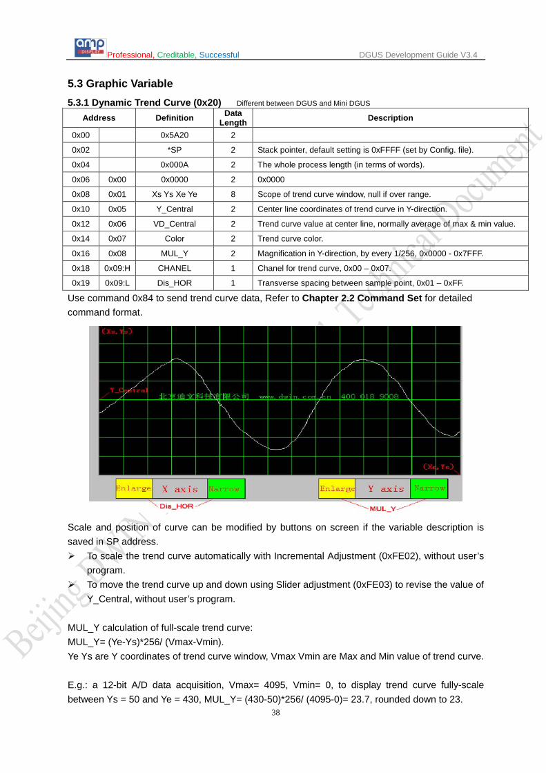
5.3 Graphic Variable 5.3.1 Dynamic Trend Curve (0x20)
Address Definition Data Length Description
0x00 0x5A20 2
0x02 *SP 2 Stack pointer, default setting is 0xFFFF (set by Config. file).
0x04 0x000A 2 The whole process length (in terms of words).
0x06 0x00 0x0000 2 0x0000
0x08 0x01 Xs Ys Xe Ye 8 Scope of trend curve window, null if over range.
0x10 0x05 Y_Central 2 Center line coordinates of trend curve in Y-direction.
0x12 0x06 VD_Central 2 Trend curve value at center line, normally average of max & min value.
0x14 0x07 Color 2 Trend curve color.
0x16 0x08 MUL_Y 2 Magnification in Y-direction, by every 1/256, 0x0000 - 0x7FFF.
0x18 0x09:H CHANEL 1 Chanel for trend curve, 0x00 – 0x07.
0x19 0x09:L Dis_HOR 1 Transverse spacing between sample point, 0x01 – 0xFF.
Use command 0x84 to send trend curve data, Refer to Chapter 2.2 Command Set for detailed command format.
Scale and position of curve can be modified by buttons on screen if the variable description is saved in SP address. To scale the trend curve automatically with Incremental Adjustment (0xFE02), without user’s
program. To move the trend curve up and down using Slider adjustment (0xFE03) to revise the value of
Y_Central, without user’s program. MUL_Y calculation of full-scale trend curve: MUL_Y= (Ye-Ys)*256/ (Vmax-Vmin). Ye Ys are Y coordinates of trend curve window, Vmax Vmin are Max and Min value of trend curve. E.g.: a 12-bit A/D data acquisition, Vmax= 4095, Vmin= 0, to display trend curve fully-scale between Ys = 50 and Ye = 430, MUL_Y= (430-50)*256/ (4095-0)= 23.7, rounded down to 23.

Professional, Creditable, Successful DGUS Development Guide V3.4
39
Different between DGUS and Mini DGUS 5.3.2 Basic Graphic Display (0x21) Address Definition Data
Length Description
0x00 0x5A21 2
0x02 *SP 2 Stack pointer, default setting is 0xFFFF (set by Config. file).
0x04 0x0005 2 The whole process length (in terms of words).
0x06 0x00 *VP 2 Variable pointer.
0x08 0x01 Area 8 Graphic window area for commands 0x0001 – 0x0005, null if over range.
String Format Address Definition Description
VP CMD Command.
VP+1 Data_Pack_Num_Max Max number of data packs. For command 0x0002, it’s number of beelines.
VP+2 DATA_Pack Data
Data Pack for Basic Graphic
CMD Function Description of Data Pack, by word
Relative Address
Data Length Definition Description
0x0001 Dot 0x00 2 (x, y) Dot coordinates, high byte of X coordinate is judgment
condition 0x02 1 Color Dot color.
0x0002 Line
0x00 1 Color Line color.
0x01 2 (x, y)0 Vertex 0 coordinates, high byte of X coordinate is judgment condition
0x03 2 (x, y)1 Vertex 1 coordinates, high byte of X coordinate is judgment condition
0x01+2*n 2 (x, y)n Vertex n coordinates, high byte of X coordinate is judgment condition
0x0003 Rectangle 0x00 2 (x, y)s Top-left coordinates, high byte of X coordinate is judgment
condition 0x02 2 (x, y)e Bottom-right coordinates. 0x04 1 Color Rectangle’s color.
0x0004 Rectangle Area Fill
0x00 2 (x, y)s Top-left coordinates, high byte of X coordinate is judgment condition
0x02 2 (x, y)e Bottom-right coordinates. 0x04 1 Color Filled color.
0x0005 Circle 0x00 2 (x, y) Circle center coordinates, high byte of X coordinate is
judgment condition 0x02 1 Rad Radius of circle. 0x03 1 Color Circle color.
0x0006 Picture Cut/Paste
0x00 1 Pic_ID Image ID of cutting area, high byte of X coordinate is judgment condition
0x01 2 (x, y)s Top-left coordinates of the cutting area. 0x03 2 (x, y)e Bottom-right coordinates of the cutting area. 0x05 2 (x, y) Paste position on current screen, upper left coordinate
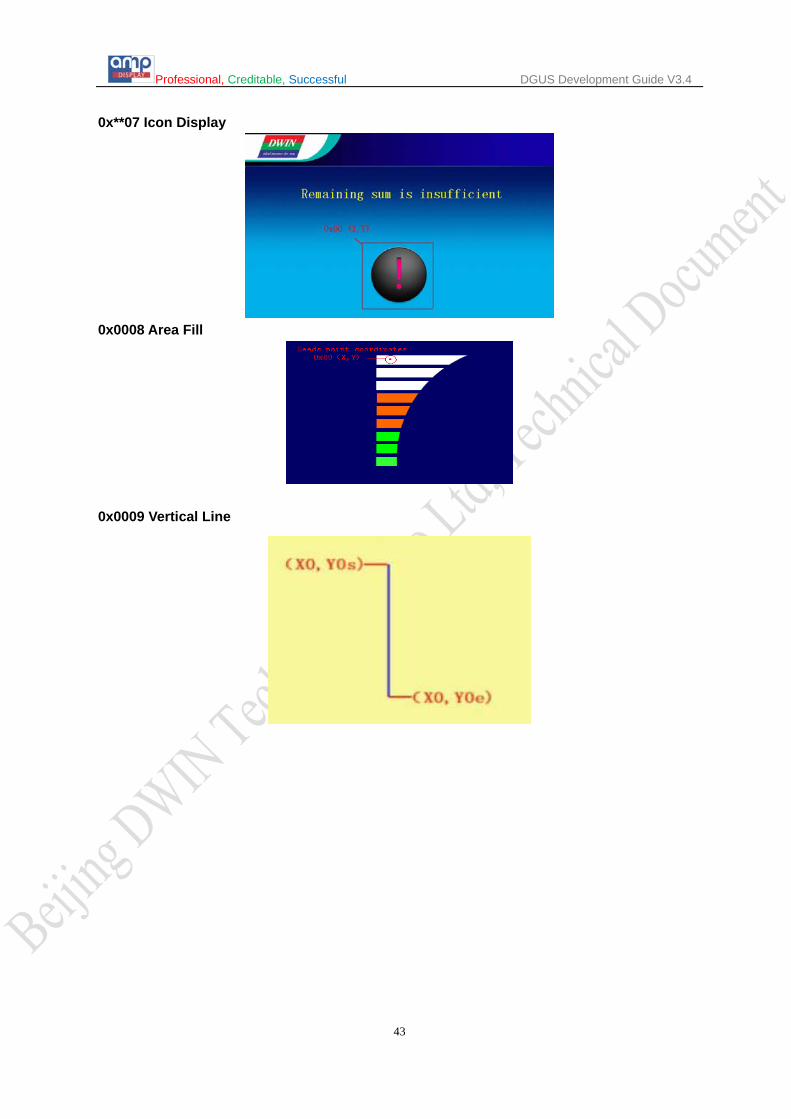
0x**07 Icon Display 0x00 2 (x, y) Top-left coordinates of icon, high byte of X coordinate is
judgment condition
0x02 1 ICON_ID Icon ID in icon file, high byte of command specifies address of icon file, display mode is transparent.
0x0008 Area Fill 0x00 2 (x, y) Sampling dot coordinates, high byte of X coordinate is
judgment condition 0x02 1 Color Filled color.

Professional, Creditable, Successful DGUS Development Guide V3.4
40
0x0009 Vertical Line
0x00 1 Color0
Connect (X0, Y0s), (X0, Y0e) with color0, high byte of X coordinate is judgment condition
0x01 1 X0 0x02 1 Y0s 0x03 1 Y0e
0x000A Segment
0x00 1 Color
Connect (Xs, Ys), (Xe, Ye) with Color, high-byte of Xs is judging condition.
0x01 1 Xs 0x02 1 Ys 0x03 1 Xe 0x04 1 Ye
0x000B Arc Display
0x00 1 Color0 Arc color
0x01 2 (X,Y)0 Central point value, high byte of X-value is criteria 0x03 1 RAD0 radius 0x04 1 DEG_S0 Initial angle, unit 0.5°, 0-720 0x05 1 DEG_E0 Terminated angle, unite 0.5°,0-720
0x000C Character
0x00 1 Color0 Charter color 0x01 2 (X,Y)0 Position and upper-left point coordinate. X-value is criteria
0x03H 0.5 Lib_ID Font position
0x03L 0.5 En_Mode character encoding scheme: 0=8bit 1=GB2312 2=GBK 3=BIG5 4=SJIS 5=UNICODE
0x04H 0.5 X_Dots Lattice in X direction 0x04L 0.5 Y_Dots Lattice in Y direction
0x05 1 Text0 Character data, only valid on high byte of 8-bit encode. If encoding is 01-04 and ASCII data, default No.0 font will be used for display.
0x000D Rectangle XOR
0x00 2 (x,y)s Upper left coordinate of rectangle area. High byte of X coordinate is judgment condition
0x02 2 (x,y)e Lower right corner coordinate of rectangle area 0x04 1 Color XOR color and 0xFFFF for opposite color operation
0x000E bicolorable graph
0x00 2 (x,y)s Upper left coordinate of bitmap, high byte of X coordinate is judgment condition
0x02 1 X_Dots Lattice in X direction 0x03 1 Y_Dots Lattice in Y direction 0x04 1 Color1 The color that corresponded to “1”bit
0x05 1 Color0 The color that corresponded to “1”bit, if set Color0 same as Color1 which means “0” bit is no need to display, just skip it directly
0x06 N Data_Pack Data display with MSB. Considering the conveniences of data write and read, each line have to align to one word, namely next line should always start from a new data word.
0x000F Bitmap 0x00 2 (x,y)s Upper left coordinate of bitmap, high byte of X coordinate is judgment condition。
0x02 1 X_Dots Lattice in X direction 0x03 1 Y_Dots Lattice in Y direction
0x04 N Data_Pack Data display, each word occupies one dot(MSB,5R6G5B data format)
Condition: 0xFF: current drawing operation finished. 0xFE: the operation will be ignored.

Professional, Creditable, Successful DGUS Development Guide V3.4
41
0x0001 Dot
0x0002 Line
0x0003 Rectangle
0x0004 Rectangle Area Fill

Professional, Creditable, Successful DGUS Development Guide V3.4
42
0x0005 Circle
0x0006 Picture Cut/Paste
Professional, Creditable, Successful DGUS Development Guide V3.4
43
0x**07 Icon Display
0x0008 Area Fill
0x0009 Vertical Line

Professional, Creditable, Successful DGUS Development Guide V3.4
44
Not applicable for Mini DGUS. 5.3.3 Table Display (0x22) Address Definition Data
Length Description
0x00 0x5A22 2 0x02 *SP 2 Stack pointer, default setting is 0xFFFF (set by Config. file). 0x04 0x000C 2 The whole process length (in terms of words). 0x06 0x00 *VP 2 Starting VP address of data in table. 0x08 0x01:H TAB_X_Num 1 Column number, 0x01 - 0xFF. 0x09 0x01:L TAB_Y_Num 1 Row number, 0x01 - 0xFF. 0x0A 0x02:H TAB_X_Start 1 Starting column to be displayed, 0x00 - 0xFF. 0x0B 0x02:L TAB_Y_Start 1 Starting row to be displayed, 0x00 - 0xFF.
0x0C 0x03:H Unit_Data_Num 1
0x01 - 0x7F: data length for one cell. 0x00: data in VP address defines the length of each column. When Unit_Data_Num is 0x00 the starting address of data will be (row number/2, round up to integer) backward from VP address.
0x0D 0x03:L Encode_Mode 1
.7 Automatically adjustment of spacing in text display .7=0 adjust it automatically; .7=1 manual adjustment and character width set as fixed number
of dots .6 Sheet content format .6=0 text display; .6=1 first two words indicates the format as reference bellowing .5 Boarder line display .5=0 display boarder line .5=1 do not display .4 Undefined, write 0. .3-.0 Text code 0=8bit 1=GB2312 2=GBK 3=BIG5 4=SJIS 5=UNICODE
0x0E 0x04 Xs Ys Xe Ye 8 Table area, top-left and bottom-right coordinates. 0x16 0x08 Color_line 2 Boarder color. 0x18 0x09 Color_text 2 Text color.
0x1A 0x0A:H Font0_ID 1 Address of font for encoding mode 0x01 - 0x04.
0x1B 0x0A:L Font1_ID 1 Address of font for encoding mode 0x00 and 0x05.
0x1C 0x0B:H Font_X_Dots 1 Font size in X-direction.
0x1D 0x0B:L Font_Y_Dots 1 Font size in Y-direction.
0x1E 0x0C:H TAB_X_Adj_Mod 1 Displaying or not the column header when TAB_X_Start is NOT 0.
0x00: valid display, 0x01: invalid display.
0x1F 0x0C:L TAB_Y_Adj_Mod 1 Displaying or not the row header when TAB_Y_Start is NOT 0. 0x00: valid display, 0x01: invalid display.
Reference: When Encode_mode.6=1, first two words of each table cell indicates the format of table, which is shown as below: High byte of the first word:
0x00=integer (2 bytes) range from -32768 to 32767 0x01=long integer (4 bytes) range from -2147483648 to 2147483647 0x02=*VP high byte, unsigned number range from 0 to 255 0x03=*VP low byte, unsigned number range from 0 to 255 0x04= overlength integer (8 bytes) range from -9223372036854775808 to 9223372036854775807 0x05=unsigned integer (2 bytes) range from 0 to 65535 0x06= unsigned long integer (4 bytes) range from 0 to 4294967295 0x10= time format One,12:34:56 BCD 0x11= time format Two,12-34-56 BCD 0x12= time format Three,YYYY-MM-DD HH:MM:SS BCD 0xFF=Text format
First word of low byte:

Professional, Creditable, Successful DGUS Development Guide V3.4
45
Not applicable for Mini DGUS.
Mode=0x00-0x06 fixed-point format of the variable data,he high 4bit shows integer digits and the low 4bit signified decimal
digits. Mode=0x10-0X11 : Byte length of BCD Mode=Others : Undefined
Second word: text color
If the actual content is shorter than the prescript length of the Unit Data_Num, 0xFFFF has been used as the terminator of cell text the particularly large tables have been modified by value of TAB_X_Start、TAB_Y_Start via touch screen in order to drag and move
5.3.4 Special Industrial Application (0x23) This function has been removed in V5.3 and above version.
Address Definition Data Length Description
0x00 0x5A23 2
0x02 *SP 2 Stack pointer, default setting is 0xFFFF (set by Config. file).
0x04 0x0001 2 The whole process length (in terms of words).
0x06 0x00 *VP 2 Variable pointer.
0x08 24 0x00 fixed.
Data String Format. Address Definition Description
VP CMD Command.
VP+1 Data_Pack_Num_Max Data Pack Number. Automated termination as of end condition
VP+2 DATA_Pack
Data Pack for Special Industrial Application
CMD Function Description of data pack, by word
Relative Address Length Definition Description
0x0001
Overlapped Area of Multiple
Circles Fill
0x00 1 Color0 Color of “Safe Zone”.
0x01 1 Color1 Color of normally overlapped area (Overlapped once).
0x02 1 Color2 Color of High-Risk overlapped area (Overlapped twice or more).
0x03 1 Color3 Color of circles.
0x04 1 Color4 Color of evasion(unfilled text color or grid)
0x05 4 Disp_Area Display area, null if over range.
0x09+4*n 2 (x, y)n Center coordinates of No. n. 0xFF in high byte of X coordinate signify null
0x0B+4*n 1 RADn_1 The bigger radius of No. n concentric circles.
0x0C+4*n 1 RAD2n_2 The smaller radius of No. n concentric circles.

Professional, Creditable, Successful DGUS Development Guide V3.4
46

Professional, Creditable, Successful DGUS Development Guide V3.4
47
Appendix 1: DGUS Main Functions
① Variable input and display: 0xFE00 Variable Data Input (popup keypad which is not on the current page), 0x5A10 Variable Data Display. ② Variable adjustment (“++”, “--”) and display: 0xFE02 Adjustment of Variable data, 0x5A10 Variable Data Display. ③ Variable adjustment (drag with following slider): 0xFE03 Slider Adjustment, 0x5A02 Slider Scale Indicator. ④ Time set and display: 0xFE04 RTC Set (similar to 0xFE00 Variable Data Input), 0x5A12 RTC Display (Two mode of time display: digital and analog). ⑤ Scale bar, status bar: 0x5A00 Variable Icon Display (Display different icons corresponding to the different variable values), 0x5A01 Animation Icon Display (When the variable is a specified value, display multiple icons circulation animation in proper order). ⑥ Dashboard: 0x5A05 Icon Rotation Instructions. ⑦ Text input and display: 0xFE06 Text In-put, 0x5A11 Text display.
⑧ Boot animation, electronic album: 0x5A04 Image Animation. ⑨Table display, drag and print: 0x5A22 Table Display, 0xFE03 Slider Adjustment, 0x5A02 Slider Scale Indicator, 0xFE07 Firmware parameter Configuration.

Professional, Creditable, Successful DGUS Development Guide V3.4
48
⑩ Display and adjust the trend curve: 0x5A20 Trend curve Display (Support up to eight channels simultaneously receive data and show the real-time trend curve), 0xFE03 Slider Adjustment, 0x5A02 Slider scale indicator, 0xFE02 Incremental Adjustment. Adjustment of the trend curve scaling and central axis position can be achieved without code interference.

Professional, Creditable, Successful DGUS Development Guide V3.4
49
Appendix 2: Mini DGUS Mini DGUS is designed with the ARM kernel and is for lower-cost applications. As its name implies, Mini DGUS performs most of the more commonly used functions of DGUS at a significant cost savings. UART communication CRC checksum is not supported for Mini DGUS. Refer to chapter 2.1. Upgrade firmware via SD card is not included, , but the user can upgrade firmware via UART
serial port. Refer to chapter 1.4. User can’t save data in font addresses or transport data. Refer to chapter 1.3. In the user-defined baud rate, only 16 standard baud rates are supported. Refer to chapter
1.2. Firmware Parameter Settings (FE07): modify parameter settings by touchscreen,
monochrome bitmap printing etc. Refer to chapter 4.8. Area Fill (5A21_08): fill an area of same color with designated color. Refer to chapter 5.3.2. Table Display (5A22): display a table of designated columns and rows numbers, with contents.
Refer to chapter 5.3.3. Special Industrial Application (5A23): aiming at tower crane field. Refer to chapter 5.3.4. DWIN OS: user’s program based on DGUS. Refer to chapter 1.7. Timer: 4 built-in software timers. Refer to chapter 1.3. Additionally, some functions are altered as shown below. Flash memory is reduced from 256MB to 128MB. Refer to chapter 1.3. Variable SRAM is reduced from 56KB to 4KB divided into 2048 addresses. Refer to chapter
1.3. Real-time Trend Curves (5A20) are reduced from 8 to 2. Refer to chapter 5.3.1. There are also 2 refresh rate modes in Mini DGUS: 100ms and 200ms, default is 100ms.
Change the refresh rate: register R2 in config.txt, modify the value of .7 bit, 0: 100ms, 1: 200ms. Refer to chapter 1.2.

Professional, Creditable, Successful DGUS Development Guide V3.4
50
Appendix 3: Command Illustration Configure frame header and baud rate in CONFIG.TXT via DGUS SDK as below: R1=07; baud rate is 115200 R3=5A; Frame header high byte RA=A5; Frame header low byte
Frame header (2 Bytes)+Data length (1 Byte)+Command (1 Byte)+Data (N Byte: ADR+data/LEN)+CRC (2 Bytes) 1. Access Register of DGUS (0x80/0x81) 1.1 Write Data into Register (0x80) e.g.: Switch current picture to pic_3:
Professional, Creditable, Successful DGUS Development Guide V3.4
51
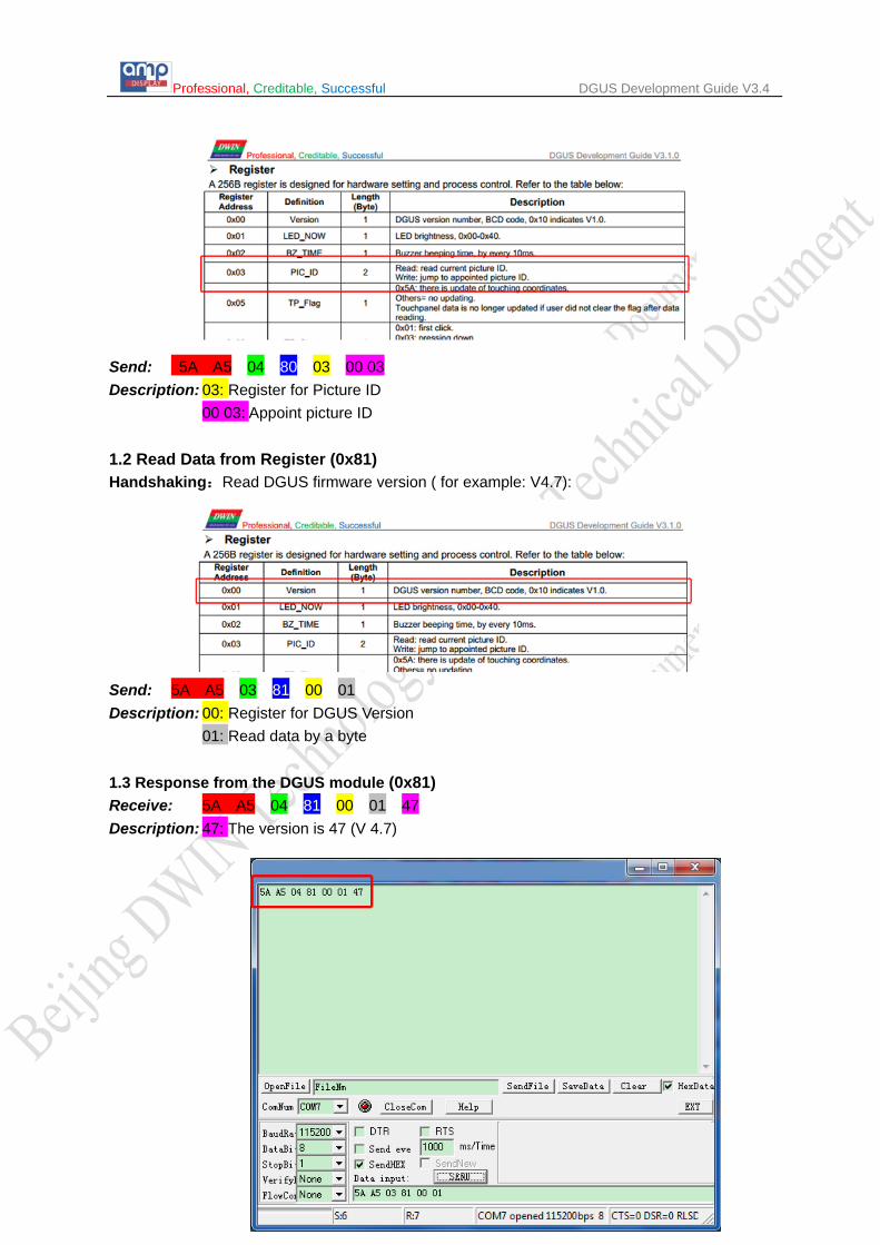
Send: 5A A5 04 80 03 00 03 Description: 03: Register for Picture ID
00 03: Appoint picture ID
1.2 Read Data from Register (0x81) Handshaking:Read DGUS firmware version ( for example: V4.7):
Send: 5A A5 03 81 00 01 Description: 00: Register for DGUS Version
01: Read data by a byte 1.3 Response from the DGUS module (0x81) Receive: 5A A5 04 81 00 01 47 Description: 47: The version is 47 (V 4.7)
Professional, Creditable, Successful DGUS Development Guide V3.4
52
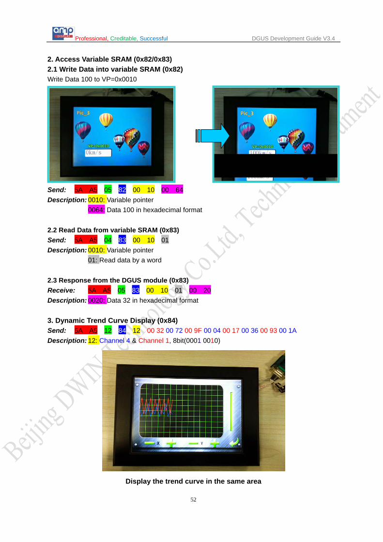
2. Access Variable SRAM (0x82/0x83) 2.1 Write Data into variable SRAM (0x82) Write Data 100 to VP=0x0010
Send: 5A A5 05 82 00 10 00 64 Description: 0010: Variable pointer
0064: Data 100 in hexadecimal format 2.2 Read Data from variable SRAM (0x83) Send: 5A A5 04 83 00 10 01 Description: 0010: Variable pointer
01: Read data by a word 2.3 Response from the DGUS module (0x83) Receive: 5A A5 05 83 00 10 01 00 20 Description: 0020: Data 32 in hexadecimal format 3. Dynamic Trend Curve Display (0x84) Send: 5A A5 12 84 12 00 32 00 72 00 9F 00 04 00 17 00 36 00 93 00 1A Description: 12: Channel 4 & Channel 1, 8bit(0001 0010)
Display the trend curve in the same area

Professional, Creditable, Successful DGUS Development Guide V3.4
53
Display the trend curve in the different area simultaneously
4. Basic Graphic Display String Format
Address Definition Description
VP CMD Command.
VP+1 Data_Pack_Num_Max Max number of data packs. For command 0x0002, it’s number of graph.
VP+2 DATA_Pack
Date Pack for Basic Graphic
CMD Function Description of Data Format, by word
Relative Address
Data Length Definition Description
0x0001 Dot 0x00 2 (x, y) Coordinate of dot.
0x02 1 Color Color of dot.
0x0002 Line
0x00 1 Color Color of line.
0x01 2 (x, y)0 Coordinate of vertex 0.
0x03 2 (x, y)1 Coordinate of vertex 1.
0x01+2*n 2 (x, y)n Coordinate of vertex n.
0x0003 Rectangle
0x00 2 (x, y)s Coordinate of top-left.
0x02 2 (x, y)e Coordinate of bottom-right.
0x04 1 Color Color of rectangle.
0x0004 Rectangle Area Fill
0x00 2 (x, y)s Coordinate of top-left.
0x02 2 (x, y)e Coordinate of bottom-right.
0x04 1 Color Filled color.
0x0005 Circle
0x00 2 (x, y) Coordinate of center of circle.
0x02 1 Rad Radius of circle.
0x03 1 Color Color of circle.

Professional, Creditable, Successful DGUS Development Guide V3.4
54
0x0006 Picture Cut/Paste
0x00 1 Pic_ID Image ID of cutting area.
0x01 2 (x, y)s Coordinate of top-left of cutting area.
0x03 2 (x, y)e Coordinate of bottom-right of cutting area.
0x05 2 (x, y) Paste position on current screen.
0x**07 Icon Display 0x00 2 (x, y) Coordinate of top-left of icon.
0x02 1 ICON_ID Icon ID in icon file, high byte of command specifies address of icon file, display mode is transparent.
0x0008 Area Fill 0x00 2 (x, y) Coordinate of sampling dot.
0x02 1 Color Filled color.
0x0009 Vertical Line
0x00 1 Color0
Connect (X0, Y0s), (X0, Y0e) with color0. 0x01 1 X0
0x02 1 Y0s
0x03 1 Y0e
Status Flag: 0xFF Current drawing operation finished. 0xFE This operation will be skipped (ignored). Take Circle Drawing for example
1) Add a basic graphic display via DGUS SDK software and set vp to 0x00A0 as below:

Professional, Creditable, Successful DGUS Development Guide V3.4
55
2) Send commands by serial port
Send: 5A A5 11 82 00 A0 00 05 00 01 01 64 00 EF 00 64 F8 00 FF 00
Hex Description 5A A5 Frame header
11 Data length 82 Command
00 A0 VP 00 05 Circle command 00 01 One circle
01 64 X coordinate of center of circle:356
00 EF Y coordinate of center of circle:239
00 64 Radius of circle:100 F8 00 Color: red FF 00 Drawing operation finished

Professional, Creditable, Successful DGUS Development Guide V3.4
56
Appendix 4: DGUS_SDK Guide 1. DGUS_SDK Instruction
1.1 Operation of DGUS_SDK
1.1.1 DGUS (DWIN Graphical Utility Software) is an intelligent GUI design software for DWIN DGUS LCM with K600+. By using DGUS, magnificent display effect can be achieved easily and rapidly with much less programming than ever before. Variables are defined by DGUS_SDK and users can feel free to design the visualize GUI. All parameters and images can be downloaded via SD card which stores related .bin files to make your design into real application. 1.1.2. Install DGUS_SDK_V4.9: Unzip DGUS_SDK_V4.9.rar, and click DGUS ToolV4.9.exe to run it. (.net Framework 2.0 is required to run the software).
1.1.3. Variable Definition VP (Variable Pointer): The addresses of variables in variable SRAM (56KB). Users can set
buttons with defined VP, to change the value in this address and display contents corresponding with the value in VP address.
SP (Stack Pointer): the address of definitions, starting address of description data of
variables. Change the value in particular address to modify variable properties. Take <WordArt> function as example.
Add. Definition Data Length Description
0x00 0x5A03 2
0x02 *SP 2 Stack pointer, default setting is 0xFFFF.
0x04 0x0007 2 The whole process length (in terms of words).
0x06 0x00 *VP 2 Variable pointer.
0x08 0x01 X,Y 4 Top-left coordinate of text, left aligned.
0x0C 0x03 Icon0 2 Icon ID corresponding to 0, the sequence is “0123456789-.”.
0x0E 0x04:H Icon_Lib 1 Address of icon file.
0x0F 0x04:L Icon_Mode 1 ICON display mode. 0x00: transparent, others: opaque.
0x10 0x05:H Int_Num 1 Length of integer digits.
0x11 0x05:L Dec_Num 1 Length of decimal digits.
0x12 0x06:H VP_Data_Mode 1 0x00: integer (2 bytes), 0x01: long integer (4 bytes).
E.g.: If SP valued as 0x5000 for WordArt variable, VP parameter will be saved in the ADDRESS of 0x5000. Variable position parameters will be saved in 0x5001-0x5002
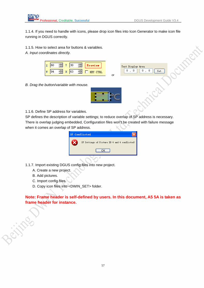
Professional, Creditable, Successful DGUS Development Guide V3.4
57
1.1.4. If you need to handle with icons, please drop icon files into Icon Generator to make icon file running in DGUS correctly. 1.1.5. How to select area for buttons & variables. A. Input coordinates directly.
or
B. Drag the button/variable with mouse.
1.1.6. Define SP address for variables. SP defines the description of variable settings; to reduce overlap of SP address is necessary. There is overlap judging embedded, Configuration files won’t be created with failure message when it comes an overlap of SP address.
1.1.7. Import existing DGUS config.files into new project. A. Create a new project. B. Add pictures. C. Import config files. D. Copy icon files into <DWIN_SET> folder.
Note: Frame header is self-defined by users. In this document, A5 5A is taken as frame header for instance.

Professional, Creditable, Successful DGUS Development Guide V3.4
58
1.2 Main Interface of DGUS_SDK_V49
a) Click <New Project> to activate the window below:
b) Select resolution and path for your project.
Screen Property Set. E.g. for:
DMT80480T070_06WT. Color T: 16bit. Resolution 80480: 800x480.

Professional, Creditable, Successful DGUS Development Guide V3.4
59
Navigation Bar: New Create a new project. Open Open an existing project (.hmi file). Save Save the current project. Save As Save the current project in a new folder. Close Close the current project. Resolution Modify resolution of project. System Properties Modify system properties and save the settings in config.txt. Refer to
illustration below Create Config. Generate <13Touch_Control_Config.bin> and <14Variable_Config.bin>.
Import Config. Import existing config. files to the current project. Variable Export Generate <TouchConfig.xls> and <DisplayConfig.xls> for quick view of
buttons & variables. Align Left Align the selected buttons and variables to left.
Align Top Align the selected buttons and variables to right Auto Width Adjust the selected buttons & variables at same width. Auto Height Adjust the selected buttons & variables at same height. Copy (Ctrl + C): copy Paste (Ctrl + V): paste Delete (delete): delete Front Place the button or variable at front layer. Back Place the button or variable at backward layer. SP Address Setting Set SP for variables. Variables Preview Preview buttons & variables Show Text show the names of buttons & variables or not. Reference:Inputted data will be sent via serial port only when both <TPSAUTO> in System Config. Window and <Data Auto Upload> settings in buttons properties are ticked.
ToolBar: Switching between "Touch Config" & "Variable Config" & Edit Tools using Navigation bar, or shortcut key F2, F3, F4.
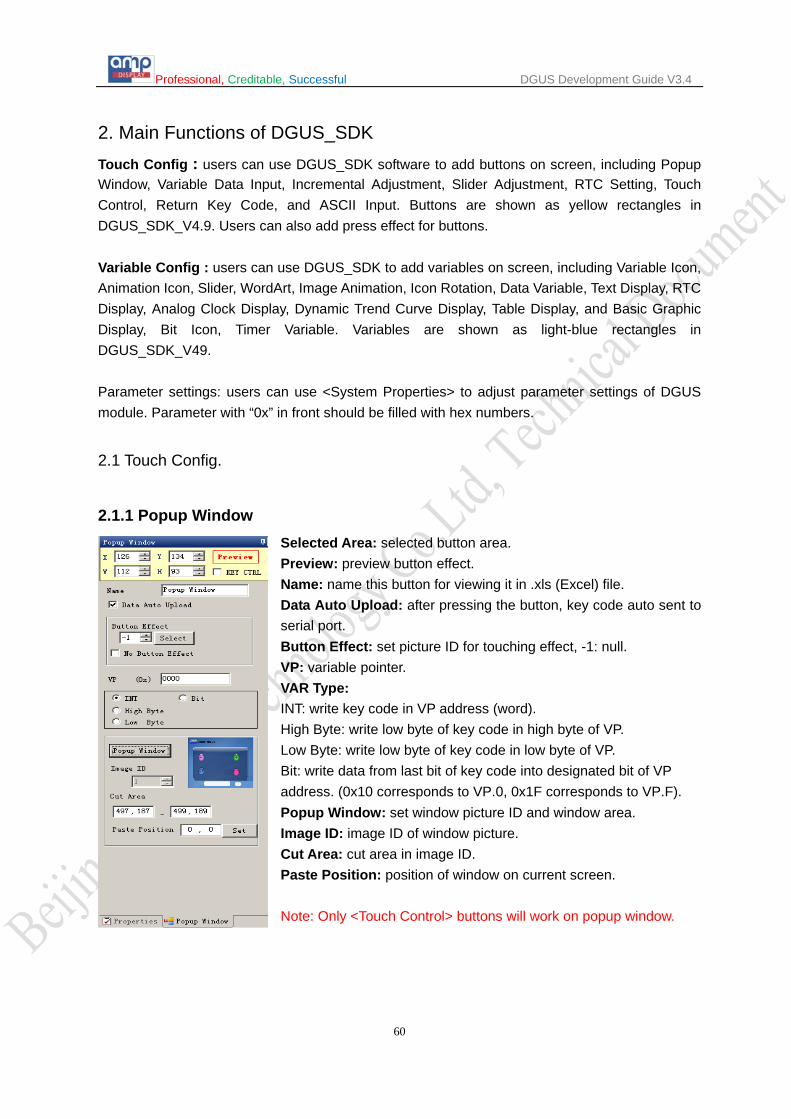
Professional, Creditable, Successful DGUS Development Guide V3.4
60
2. Main Functions of DGUS_SDK Touch Config : users can use DGUS_SDK software to add buttons on screen, including Popup Window, Variable Data Input, Incremental Adjustment, Slider Adjustment, RTC Setting, Touch Control, Return Key Code, and ASCII Input. Buttons are shown as yellow rectangles in DGUS_SDK_V4.9. Users can also add press effect for buttons. Variable Config : users can use DGUS_SDK to add variables on screen, including Variable Icon, Animation Icon, Slider, WordArt, Image Animation, Icon Rotation, Data Variable, Text Display, RTC Display, Analog Clock Display, Dynamic Trend Curve Display, Table Display, and Basic Graphic Display, Bit Icon, Timer Variable. Variables are shown as light-blue rectangles in DGUS_SDK_V49. Parameter settings: users can use <System Properties> to adjust parameter settings of DGUS module. Parameter with “0x” in front should be filled with hex numbers. 2.1 Touch Config.
2.1.1 Popup Window Selected Area: selected button area. Preview: preview button effect. Name: name this button for viewing it in .xls (Excel) file. Data Auto Upload: after pressing the button, key code auto sent to serial port. Button Effect: set picture ID for touching effect, -1: null. VP: variable pointer. VAR Type: INT: write key code in VP address (word). High Byte: write low byte of key code in high byte of VP. Low Byte: write low byte of key code in low byte of VP. Bit: write data from last bit of key code into designated bit of VP address. (0x10 corresponds to VP.0, 0x1F corresponds to VP.F). Popup Window: set window picture ID and window area. Image ID: image ID of window picture. Cut Area: cut area in image ID. Paste Position: position of window on current screen. Note: Only <Touch Control> buttons will work on popup window.
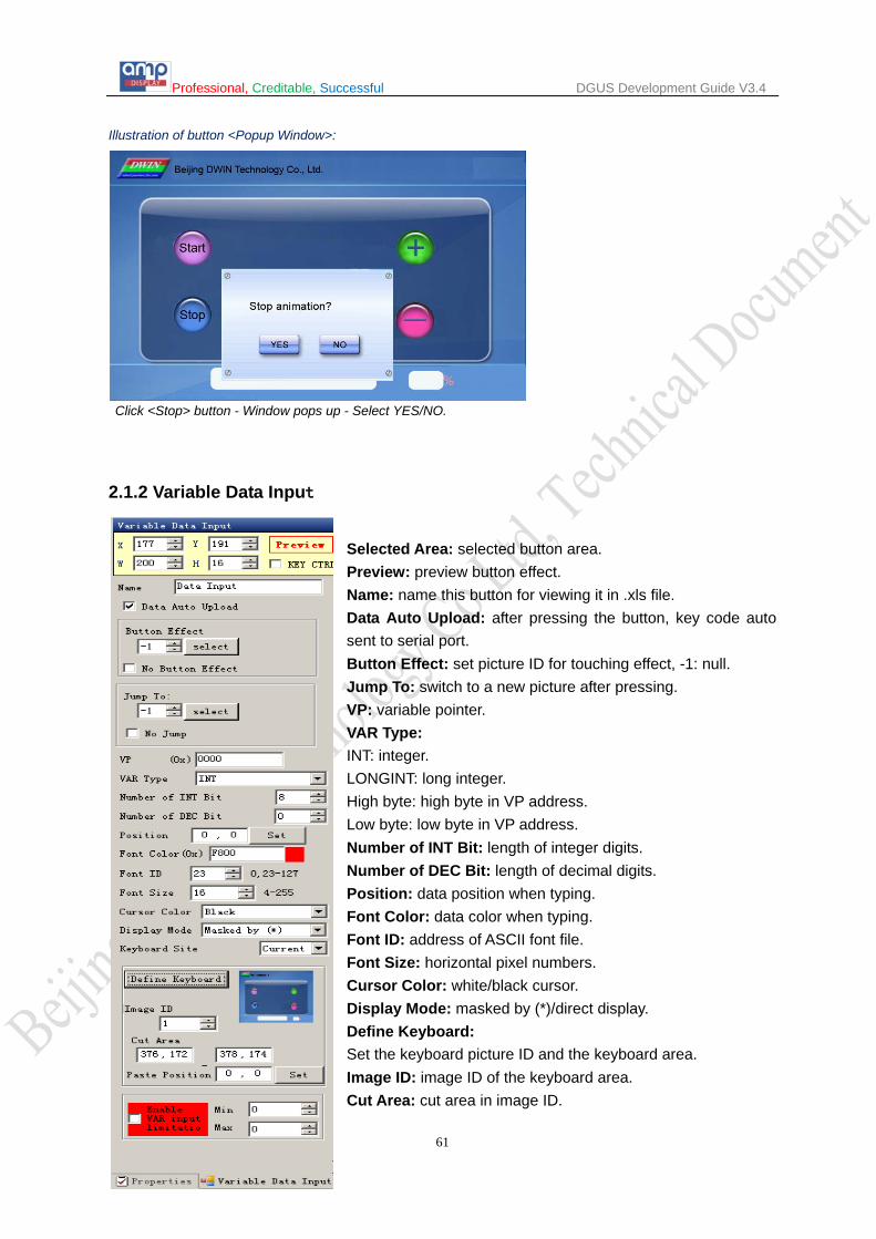
Professional, Creditable, Successful DGUS Development Guide V3.4
61
Illustration of button <Popup Window>:
Click <Stop> button - Window pops up - Select YES/NO.
2.1.2 Variable Data Input
Selected Area: selected button area. Preview: preview button effect. Name: name this button for viewing it in .xls file. Data Auto Upload: after pressing the button, key code auto sent to serial port. Button Effect: set picture ID for touching effect, -1: null. Jump To: switch to a new picture after pressing. VP: variable pointer. VAR Type: INT: integer. LONGINT: long integer. High byte: high byte in VP address. Low byte: low byte in VP address. Number of INT Bit: length of integer digits. Number of DEC Bit: length of decimal digits. Position: data position when typing. Font Color: data color when typing. Font ID: address of ASCII font file. Font Size: horizontal pixel numbers. Cursor Color: white/black cursor. Display Mode: masked by (*)/direct display. Define Keyboard: Set the keyboard picture ID and the keyboard area. Image ID: image ID of the keyboard area. Cut Area: cut area in image ID.

Professional, Creditable, Successful DGUS Development Guide V3.4
62
Paste Position: position of the keyboard on current screen. Enable VAR Input Limitation: Set limits for inputting numbers. Notes: Only <Touch Control> buttons will work on keyboard: 0x00F1 (Confirm), 0-9 corresponds to 0x0030 - 0x0039, 0x00F0 (Cancel), 0x00F2 (Backspace), 0x002D (+/-), 0x002E (.). Ignore decimal point while setting range restriction for return value. E.g.: the setting is 3 integer bits and 2 decimal bits, and then the top limit is 10000, rather than 100. Inputted data can be displayed by <Data Variable>, <WordArt> etc.
Illustration of button <Variable Data Input>:
Click text – Keyboard pops up – Type data – OK.
Click <Cancel> to interrupt input.

Professional, Creditable, Successful DGUS Development Guide V3.4
63
2.1.3 Incremental Adjustment Selected Area: selected button area. Preview: preview button effect. Name: name this button for viewing it in .xls file. Data Auto Upload: after pressing the button, key code auto sent to serial port. Button Effect: set picture ID for touching effect, -1: null. VP: variable pointer. VAR Type: 0x00: integer. 0x01: high byte in VP address. 0x02: low byte in VP address. 0x10 – 0x1F: adjust value in designated bit of VP address. (0x10 corresponds to VP.0, 0x1F corresponds to VP.F) Step Size must be 0 or 1. Adjustment Method: ++/--. Over-limit Operation: stop/ cycle. Step Size: set step size for +/- buttons. Min. Value: minimum value for adjustment. Max. Value: maximum value for adjustment.
Adjusted data can be displayed by <Data variable>, <Icon variable> and <WordArt> etc.
Illustration of button <Incremental Adjustment>:
Click <+> or <-> to adjust corresponding value.
Hold the button to adjust continually.

Professional, Creditable, Successful DGUS Development Guide V3.4
64
2.1.4 Slider Adjustment Selected Area: selected button area. Preview: preview button effect. Name: name this button for viewing it in .xls file. Data Auto Upload: after pressing the button, key code auto sent to serial port. VP: variable pointer. Value Return Type: 0x00: integer. 0x01: high byte in VP address. 0x02: low byte in VP address. Direction: horizontal/vertical. Start Return Value: The value corresponding to left/top side of slider. End Return Value: The value corresponding to right/bottom side of slider.
This function is only for making touching area for slider. To display it, please use <Slider display> function. Adjusted data can be displayed by <Data variable>, <Variable icon> etc. Illustration of button <Slider Adjustment>:
Hold the button over 0.5 second and slide the slider to modify number in the right, the value will also be changed.

Professional, Creditable, Successful DGUS Development Guide V3.4
65
2.1.5 RTC Selected Area: selected button area. Preview: preview button effect. Name: name this button for viewing it in .xls file. Data Auto Upload: after pressing the button, key code auto sent to serial port. Button Effect: set picture ID for touching effect, -1: null. Display Position: data position when typing. Font Color: data color when typing. Font Lib_ID: address of ASCII font file. Font Size: horizontal pixel numbers. Cursor Color: white/black cursor. Keyboard setting: Set the keyboard picture ID and the keyboard area. Image ID: image ID of keyboard area. Cut Area: cut area in image ID. Paste Position: position of the keyboard on current screen. Notes: A keyboard setting is the same as <Data Input>.
Use <RTC display> or <Analog clock display> to display current time. Illustration of button <RTC>:
Click <RTC> button - Keyboard Pops Up - Clock Sets Up the Current Time.

Professional, Creditable, Successful DGUS Development Guide V3.4
66
2.1.6 Touch Control Selected Area: selected button area. Preview: preview button effect. Name: name this button for viewing it in .xls file. Button Effect: set picture ID for touching effect, -1: null. Jump To: switch to a new picture after pressing. KeyValue: Only <Touch Control> button works on keyboard area. Valid key code range: 0x0030 - 0x0039 (0-9), 0x002E (.), 0x002D (+/-), 0x00F0 (Cancel), 0x00F1 (Confirm), 0x00F2 (Backspace).

Professional, Creditable, Successful DGUS Development Guide V3.4
67
2.1.7 Return Key Code Selected Area: selected button area. Preview: preview button effect. Name: name this button for viewing it in .xls file. Data Auto Upload: after pressing the button, key code auto sent to serial port. Button Effect: set picture ID for touching effect, -1: null. Jump To: switch to a new picture after pressing. KeyValue: self-defined keyValue for buttons. VP: variable pointer. VP Type: Save in VP address. Save in high byte of VP address. Save in low byte of VP address. Save in specified bit of VP address.
Illustration of button <Return Key Code>:
Set a <Return Key Code> button, of which VP is 0x000A, key value is 0x0005.
DGUS module auto uploads data 0005 to serial port as shown.

Professional, Creditable, Successful DGUS Development Guide V3.4
68
2.1.8 ASCII Input Selected Area: selected button area. Preview: preview button effect. Name: name this button for viewing it in .xls file. Data Auto Upload: after pressing the button, key code auto sent to serial port. Button Effect: set picture ID for touching effect, -1: null. Jump To: switch to a new picture after pressing. VP: variable pointer. Text Length: length of text, by word, range from 1 to 123. Input Mode: re-input/ edit text. Font Lib_ID: address of ASCII font file. Font Width: horizontal pixel numbers. Font Height: vertical pixel numbers. Cursor Color: white/black. Font Color: data color when typing. Upload value as typing: tying status upload. Text Display Area: data position on screen when typing. Keyboard Displayed in: Current Page/Other Page. Keyboard Setting: Set the keyboard picture ID and the keyboard area. Image ID: image ID of the keyboard area. Cut Area: cut area in image ID. Paste Position: position of the keyboard on current screen.
Note: Create <Touch control> buttons on keyboard to define the key code of the button (0x4161 indicates “A”).
Inputted data can be displayed with <Text display> function.
Illustration of button <ASCII Input>:

Professional, Creditable, Successful DGUS Development Guide V3.4
69
2.1.9 Firmware Parameter Settings Selected Area: selected button area. Preview: preview button effect. Name: name this button for viewing it in .xls file. Data Auto Upload: after pressing the button, key code auto sent to serial port. Button Effect: set picture ID for touching effect, -1: null. Jump To: switch to a new picture after pressing. Mode: setup mode. DataPack: data pack of setup.
Setup Mode Mode Data Pack Description Function
0x00 No No Transmit data from register to variable SRAM in 0x6F00 to 0x6FFF (low bytes).
0x01 No No Transmit data from address 0x6F00 to 0x6FFF in variable SRAM (low bytes) to register and reset module parameters including R1-R3, R5-RA.
0x02
Tran_Area Coordinates of top-left and bottom-right of area.
Convert designated area to monochrome bitmap (vertical mode) and save the data to designated VP address. A. Width (Xe-Xs+1) should be even. B. Height (Ye-Ys+1) should be multiple of 8. C. VP data format shown as below:
VP: status indicator, refreshed to 0x5555 after operation. VP+1: horizontal length, by word. (Xe-Xs+1) &0xFFFE/2 VP+2: numbers of data segment. (Ye-Ys+1) &0xFFF8/8 VP+3: bitmap data, with MSB priority.
If the key code automatically upload is enabled (R2.3=1), module will upload message (value in VP address upload to 0x5555) to serial port. The command is mainly for printing of current screen.
*VP VP address for restoring bitmap data.
0x03 *VP Variable pointer. Upload data in designated VP address to serial port. Range of Tx_LEN: 0x0001-0xFFFF. Tx_LEN Length of data to be sent.
0x04 Same function with 0x03, uploading data to COM2 (reserved port).
0x05
Tran_Area Coordinates of top-left and bottom-right of area.
Convert designated area to monochrome bitmap (horizontal mode) and save the data to designated VP address. 4. Width (Xe-Xs+1) should be multiple of 16. 5. VP data format as shown below:
VP: status indicator, refreshed to 0x5555 after operation. VP+1: horizontal length, by word. (Xe-Xs+1) &0xFFF0/16 VP+2: numbers of data segment. (Ye-Ys+1) VP+3: bitmap data, with MSB priority.
If the key code automatically upload is enabled (R2.3=1), module will upload message (value in VP address upload to 0x5555) to serial port. The command is mainly for printing of current screen.
*VP VP address for restoring bitmap data.
0x06
Frame_Head Frame header (2byte) Send the current touched position to COM2 (serial port for reserving the
system), the format is: Frame_Head + X + Y + Check (The cumulative Sum for 1 byte of X, Y) + Frame_end.
Frame_End Frame end (2byte)
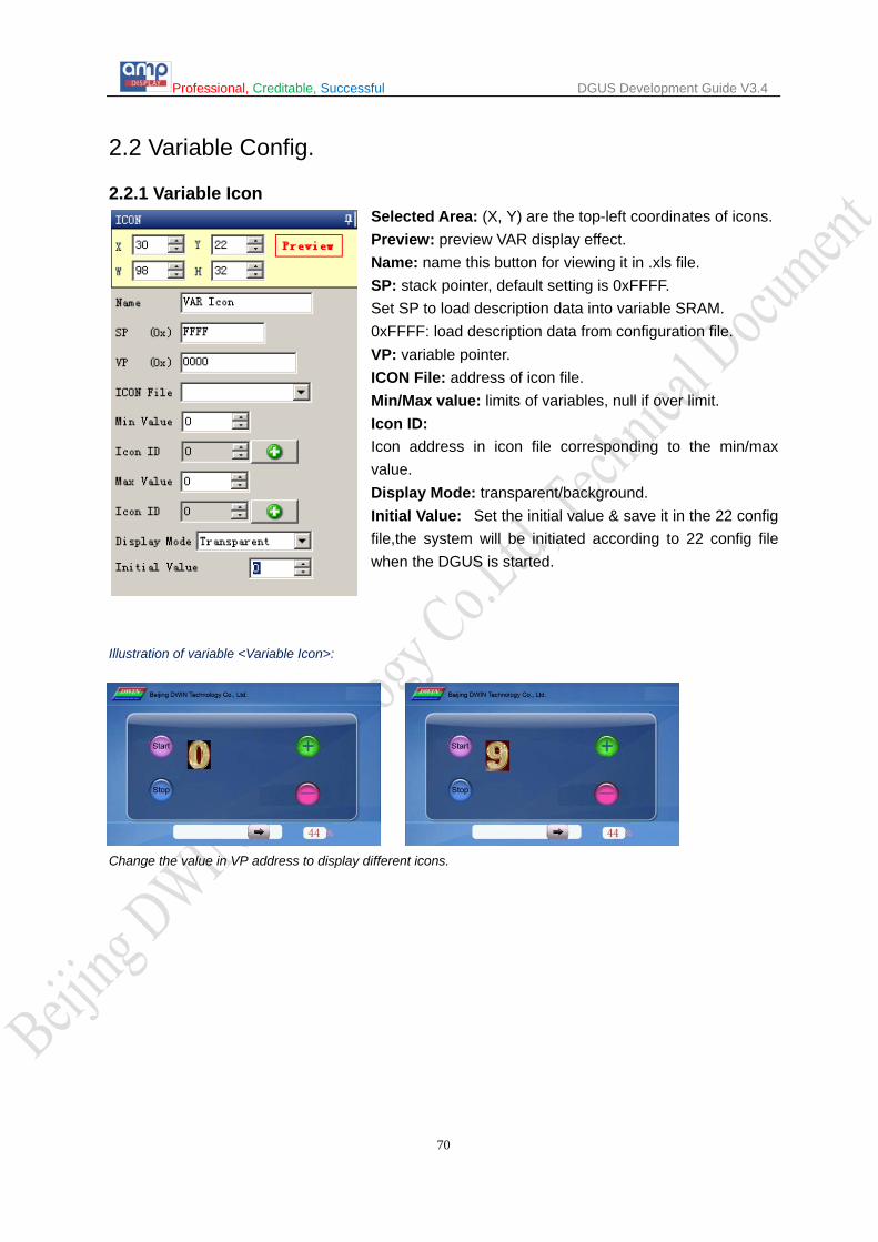
Professional, Creditable, Successful DGUS Development Guide V3.4
70
2.2 Variable Config.
2.2.1 Variable Icon Selected Area: (X, Y) are the top-left coordinates of icons. Preview: preview VAR display effect. Name: name this button for viewing it in .xls file. SP: stack pointer, default setting is 0xFFFF. Set SP to load description data into variable SRAM. 0xFFFF: load description data from configuration file. VP: variable pointer. ICON File: address of icon file. Min/Max value: limits of variables, null if over limit. Icon ID: Icon address in icon file corresponding to the min/max value. Display Mode: transparent/background. Initial Value: Set the initial value & save it in the 22 config file,the system will be initiated according to 22 config file when the DGUS is started.
Illustration of variable <Variable Icon>:
Change the value in VP address to display different icons.

Professional, Creditable, Successful DGUS Development Guide V3.4
71
2.2.2 Animation Icon Selected Area: (X, Y) are the top-left coordinates of icons. Preview: preview VAR display effect. Name: name this button for viewing it in .xls file. SP: stack pointer, default setting is 0xFFFF. VP: variable pointer. V_Stop: set value to stop animation. V_Start: set value to start animation. ICON File: address of icon file. ICON Stop: icon at V_stop value. Icon_Start/Icon_End: Start/end icon for animation at V_start Value. ICON Display Mode: transparent/background. Initial Value: Set the initial value & save it in the 22 config file,the system will be initiated according to 22 config file when the DGUS is started.
Illustration of variable <Animation Icon>:
When value in VP address is 0, screen display icon 0:
When value in VP address is 9, animation starts.
...... ......

Professional, Creditable, Successful DGUS Development Guide V3.4
72
2.2.3 Slider Selected Area: (X, Y) are the top-left coordinates of icons. X, W is start/end point of horizontal slider. Y, H is start/end point of vertical slider. Preview: preview VAR display effect. Name: name this button for viewing it in .xls file. SP: stack pointer, default setting is 0xFFFF. VP: variable pointer. Start/End Value: value corresponding to start/end point. Slider Mode: horizontal/vertical. ICON File: address of icon file. ICON ID: icon address in icon file. Display Mode: transparent/background. Coordinate Offset: Offset to the left/top. VAR Type: Integer (whole VP address). High byte in VP address. Low byte in VP address. Initial Value: Set the initial value & save it in the 22 config file,the system will be initiated according to 22 config file when the DGUS is started.
Note: Set same VP address for <Slider> button and <Slider display> variable to combine them. <Slider display> is also used as progress bar.
Send command to serial port:
Frame header, Length, Command, VP, Data string to display the Slider and Data above.
A5 5A 05 82 000C 002C

Professional, Creditable, Successful DGUS Development Guide V3.4
73
2.2.4 WordArt Selected Area: (X, Y) are the top-left coordinates of icons. Preview: preview VAR display effect. Name: name this button for viewing it in .xls file. SP: stack pointer, default setting is 0xFFFF. VP: variable pointer. ICON File: address of icon file. ICON 0: icon address corresponding to number 0. ICON Display Mode: transparent/background. VAR Type: integer/long integer. Number of INT/DEC bit: length of integer/decimal digits. Initial Value: Set the initial value & save it in the 22 config file,the system will be initiated according to 22 config file when the DGUS is started.
Illustration of variable <WordArt >:
Send command to serial port:
Frame header, Length, Command, VP, Data string to display the WordArt above. A5 5A 05 82 0CCC 0017

Professional, Creditable, Successful DGUS Development Guide V3.4
74
2.2.5 Image Animation Selected Area: (X, Y) are the top-left coordinates of icons.
Preview: preview VAR display effect. Name: name this button for viewing it in .xls file. SP: stack pointer, default setting is 0xFFFF. Start Image ID: select starting picture of animation. End Image ID: select ending picture of animation. Image Switching Time: Select switching speed for animation, by every 8ms. I
Start image ID should be less than end image ID. Set a <image animation> on end image to loop. Send commands or set <touch control> button to interrupt animation.

Professional, Creditable, Successful DGUS Development Guide V3.4
75
2.2.6 Icon Rotation Selected Area: (X, Y) are the coordinates of rotating center. Preview: preview VAR display effect. Name: name this button for viewing it in .xls file. SP: stack pointer, default setting is 0xFFFF. VP: variable pointer. ICON File: address of icon file. ICON ID: icon address in icon file. ICON Rotation Center: Select rotation center (X, Y) for the icon. Initial/End VAR Value: Value corresponding to start/end angle, null if over limit. Initial/End Rotation Angle: Select start/end angle, ranging from 0 to 720, by every 0.5°. Display Mode: transparent/background. VP_Mode: Integer (whole VP address). High byte in VP address. Low byte in VP address. Initial Value: Set the initial value & save it in the 22 config file,the system will be initiated according to 22 config file when the DGUS is started.
Send serial commands or press buttons to change value in VP address, and then to adjust the angle of pointer. Illustration of variable <Icon Rotation >:
Icons file for rotation:
Send command to serial port:
Frame header, Length, Command, VP, Data string to display the ICON above.
A5 5A 05 82 000A 0084

Professional, Creditable, Successful DGUS Development Guide V3.4
76
2.2.7 Data Variable Selected Area: (X, Y) are the top-left coordinates of data. Preview: preview VAR display effect. Name: name this button for viewing it in .xls file. SP: stack pointer, default setting is 0xFFFF. VP: variable pointer. Font Color: data color. Font Lib_ID: address of ASCII font file. Font Size: horizontal pixel numbers. Alignment Mode: Right/Left /Centered. VAR Type: 0x00: integer. 0x01: long integer. 0x02: high byte in VP address. 0x03: low byte in VP address. Number of INT Bit: length of integer digits. Number of DEC Bit: length of decimal digits. Unit Length: Corresponding to displayed unit automatically. Unit Displayed: ASCII unit for data, max length is 11 bytes. Initial Value: Set the initial value & save it in the 22 config file,the system will be initiated according to 22 config file when the DGUS is started.
Send commands or set buttons to modify displayed data. Illustration of variable <Data Variable>:
Send command to serial port:
Frame header, Length, Command, VP, Data string to display the Data (left-up) above. A5 5A 05 82 0000 0022

Professional, Creditable, Successful DGUS Development Guide V3.4
77
2.2.8 Text Display Selected Area: (X, Y) are top-left coordinates of data. Textbox is the selected area. Preview: preview VAR display effect. Name: name this button for viewing it in .xls file. SP: stack pointer, default setting is 0xFFFF. VP: variable pointer. Text Color: data color. Encoding Mode: 0x00: 8bit encoding, 0x01: GB2312, 0x02: GBK, 0x03:BIG5, 0x05: UNICODE. Set Character Interval MANUALLY: on/off. Text Length: select text length, by byte. Font0_ID: address of ASCII font file. Font1_ID: address of non-ASCII font file. Dot Matrix in X/Y-direction: select font size. Please note that parameter should be the same with the size of font file. Horizontal/Vertical Separation: Pixel distance in Horizontal/Vertical. Initial Value: Set the initial value & save it in the 22 config file,the system will be initiated according to 22 config file when the DGUS is started.
Illustration of variable <Text Display>:
Send command to serial port:
Frame header, Length, Command, VP, Data string to display the Text (bottom-left) above. A5 5A 0D 82 0008 64 77 69 6E 20 64 67 75 73 76

Professional, Creditable, Successful DGUS Development Guide V3.4
83
2.2.9 Digital RTC Display Selected Area: (X, Y) are the top-left coordinates of data. Preview: preview VAR display effect. Name: name this button for viewing it in .xls file. SP: stack pointer, default setting is 0xFFFF. Font Color: data color. Font Lib_ID: address of ASCII font file. Font Size: horizontal pixel numbers. Date Format: refer to the red texts in picture in the left. Use <RTC> button to modify current time.
Illustration of variable <Digital RTC Display> (Digital clock on bottom-right of screen):

Professional, Creditable, Successful DGUS Development Guide V3.4
84
2.2.10 Analog Clock Display
Selected Area: (X, Y) are the rotating center coordinates. Preview: preview VAR display effect. Name: name this button for viewing it in .xls file. SP: stack pointer, default setting is 0xFFFF. ICON File: address of icon file. Analog Clock:
ICON Hour: select hour hand ID in icon file. Center Coordinate: rotation center in icon.
Minute Hand: ICON Minute: select minute hand ID in icon file. Center Coordinate: rotation center in icon.
Second Hand: ICON Second: select second hand ID in icon file. Center Coordinate: rotation center in icon.
Use <RTC> button to modify current time. Illustration of variable <Analog Clock Display>:

Professional, Creditable, Successful DGUS Development Guide V3.4
85
2.2.11 Dynamic Trend Curve Selected Area: select window area, null if over range. Preview: preview VAR display effect. Name: name this button for viewing it in .xls file. SP: stack pointer, default setting is 0xFFFF. Y_Central: select center line of trend curve. VD_Central: Trend curve value at center line, normally average of Max & Min value. Curve Color: select color for trend curve. MUL_Y: magnification in Y direction, by every 1/256. Data Source Channel: select channel for trend curve. Horizontal Spacing: Transverse spacing between sampling points.
Illustration of variable <Dynamic Trend Curve Display>:
Send command to serial port:
Frame header, Length, Command, Data channel, Data string to display the trend curve above. A5 5A 18 84 01 0800 0700 0710 0733 0800 0800 0800
0800 0900 0908 0906

Professional, Creditable, Successful DGUS Development Guide V3.4
86
2.2.12 Table Display Selected Area: select table area, null if over range. Preview: preview VAR display effect. Name: name this button for viewing it in .xls file. SP: stack pointer, default setting is 0xFFFF. VP: variable pointer, starting address of the data in table. Column/Row Number: set the size of table. Start Display Column/Row: Select starting column/row to be displayed. Unit_Data_Num: 0x01-0x7F: length of data for one cell. 0x00: data in VP address defines the length of each column. When Unit_Data_Num is 00, starting address of data will be (Row number/2, round up to integer) backward from VP address. Encoding Mode: 0x00: 8bit, 0x01: GB2312, 02: GBK, 03: BIG5, 04: SJIS, 05: UNICODE. Set Character Interval MANUALLY: on/off. Boarder Color: select table boarder color. Text Color: select text color. FONT0_ID: address of ASCII font file. FONT1_ID: address of none-ASCII font file. X/Y-Direction Size: Select font size, accordant with width of fonts in font file. Column Header: Valid Display/Invalid Display. Row Header: Valid Display/Invalid Display. Data for table can be loaded by 22.bin file. Refer to DGUS document for detailed instruction.
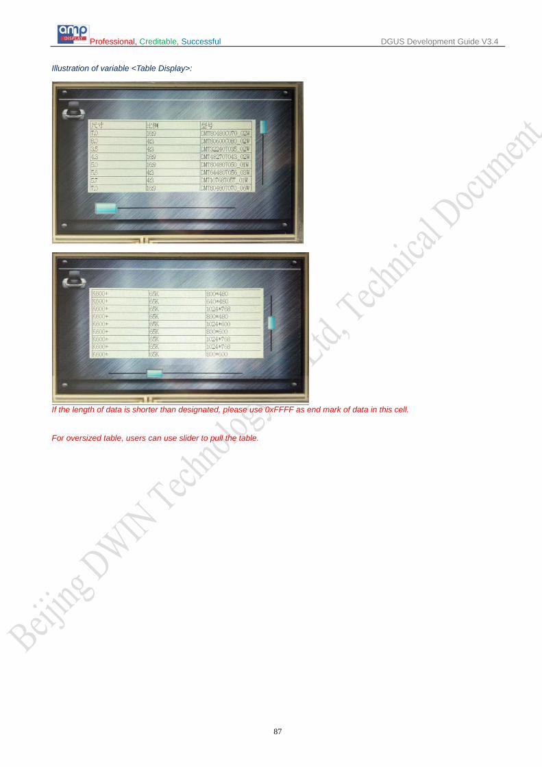
Professional, Creditable, Successful DGUS Development Guide V3.4
87
Illustration of variable <Table Display>:
If the length of data is shorter than designated, please use 0xFFFF as end mark of data in this cell.
For oversized table, users can use slider to pull the table.

Professional, Creditable, Successful DGUS Development Guide V3.4
88
2.2.13 Basic Graphic Display Selected Area: select window area, null if over range. (Limit is only effective for 0x0001 - 0x0005 commands). Name: name this button for viewing it in .xls file. SP: stack pointer, default setting is 0xFFFF. VP: variable pointer.
String Format Address Definition Description
VP CMD Command VP+1 Data_Pack_Num_Max Data Pack Number VP+2 DATA_Pack
Data Pack for Basic Graphic
CMD Function Description of Data Pack Format, by word
Relative Address Length Definition Description
0x0001 Dot 0x00 2 (x, y) Dot coordinates. 0x02 1 Color Dot color.
0x0002 Line
0x00 1 Color Line color. 0x01 2 (x, y)0 Vertex 0 coordinates. 0x03 2 (x, y)1 Vertex 1 coordinates.
0x01+2*n 2 (x, y)n Vertex n coordinates.
0x0003 Rectangle 0x00 2 (x, y)s Top-left coordinates. 0x02 2 (x, y)e Bottom-right coordinates. 0x04 1 Color Rectangle’s color.
0x0004 Rectangle Area Fill
0x00 2 (x, y)s Top-left coordinates. 0x02 2 (x, y)e Bottom-right coordinates. 0x04 1 Color Filled color.
0x0005 Circle 0x00 2 (x, y) Circle center coordinates. 0x02 1 Rad Radius of circle. 0x03 1 Color Circle color.
0x0006 Picture cut/paste
0x00 1 Pic_ID Image ID of cutting area. 0x01 2 (x, y)s Top-left coordinates of the cutting area.
0x03 2 (x, y)e Bottom-right coordinates of the cutting area.
0x05 2 (x, y) Paste position on current screen.
0x**07 Icon Display
0x00 2 (x, y) Top-left coordinates of icon.
0x02 1 ICON_ID Icon ID in icon file, high byte of command specifies address of icon file, display mode is transparent.
0x0008 Area fill 0x00 2 (x, y) Sampling dot coordinates. 0x02 1 COLOR Filled color.
0x0009 Vertical line
0x00 1 Color0
Connect (X0, Y0s) (X0, Y0e) with color 0 0x01 1 X0 0x02 1 Y0s 0x03 1 Y0e
Judging condition: 0xFF: finish operation, 0xFE: skip to next step.
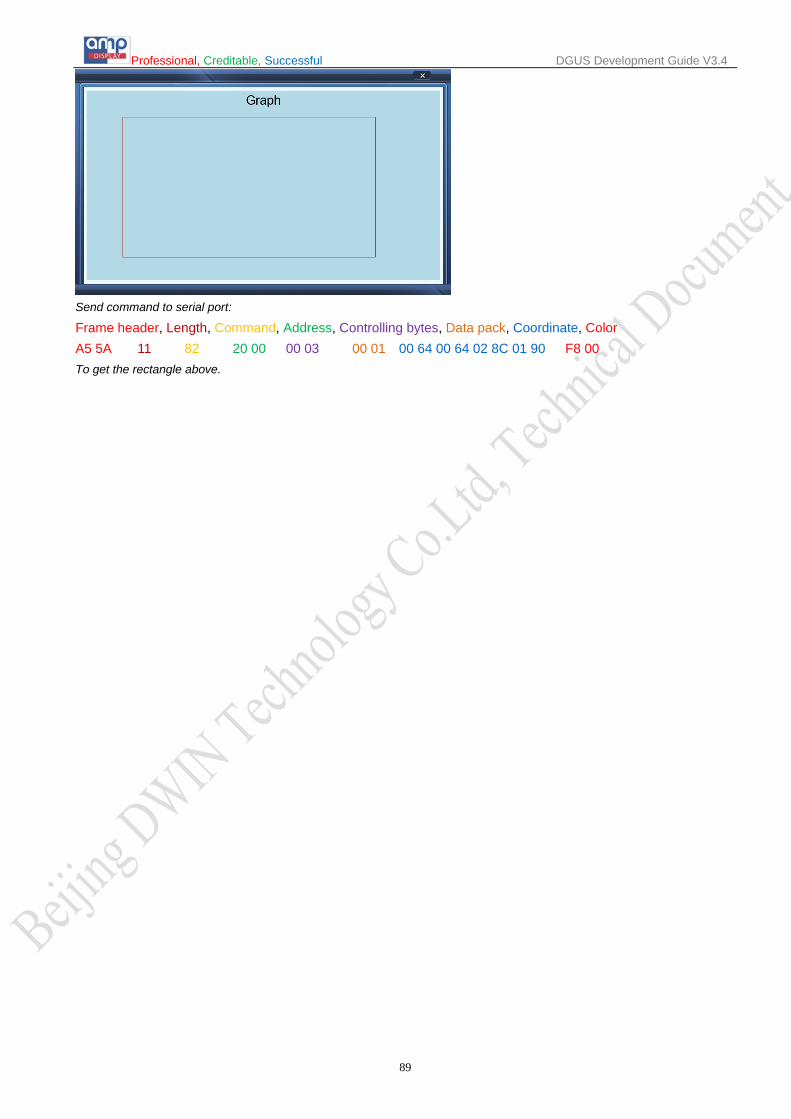
Professional, Creditable, Successful DGUS Development Guide V3.4
89
Send command to serial port:
Frame header, Length, Command, Address, Controlling bytes, Data pack, Coordinate, Color A5 5A 11 82 20 00 00 03 00 01 00 64 00 64 02 8C 01 90 F8 00 To get the rectangle above.

Professional, Creditable, Successful DGUS Development Guide V3.4
90
2.2.14 Special Industrial Application Name: name this button for viewing it in .xls file. SP: stack pointer, default setting is 0xFFFF. VP: variable pointer.
String Format Address Definition Description
VP CMD Command VP+1 Data_Pack_Num_Max Data Pack Number
VP+2 DATA_Pack
Data pack for Special Industrial Application
CMD Function Description of data pack format, by word
Relative Address Length Definition Description
0x0001
Overlapped Area of Multiple
Circles Fill
0x00 1 Color0 Color of “Safe Zone”.
0x01 1 Color1 Color of normally overlapped area (Overlapped once).
0x02 1 Color2 Color of High-Risk overlapped area (Overlapped twice or more).
0x03 1 Color3 Color of circles.
0x04 1 Color4 Color of evasion.
0x05 4 Disp_Area Display area, null if over range.
0x09+4*n 2 (x, y)n Center coordinates of No. n.
0x0B+4*n 1 RADn_1 The bigger radius of No. n concentric circles.
0x0C+4*n 1 RAD2n_2 The smaller radius of No. n concentric circles.

Professional, Creditable, Successful DGUS Development Guide V3.4
91
2.2.15 Bit Variable Icon
Selected Area: (X, Y) are coordinates of top-left of icons. Preview: preview VAR display effect. Name: name this button for viewing it in .xls file. SP: stack pointer, default setting is 0xFFFF. VP: variable pointer. AP: substitutive variable pointer, reserved 2 words. Bit Icon ON (1) /OFF (0): define BITs to display. Disp. Mode: shown as the following table. Align Mode: 0x00: X++, space unreserved for undesignated bits. 0x01: Y++, space unreserved for undesignated bits. 0x02: X++, space reserved for undesignated bits. 0x03: Y++, space reserved for undesignated bits. Interval: spacing between icons. Icon File ID: address of icon file. ICON0S: Icon ID for bit0 in non-animation mode, or starting Icon ID for bit0 in animation mode. ICON0E: ending icon ID for bit0 in animation mode. ICON1S: Icon ID for bit1 in non-animation mode, or starting Icon ID for bit1 in animation mode. ICON1E: ending icon ID for bit1 in animation mode. ICON Mode: Transparent/Opaque.
Initial Value: Set the initial value & save it in the 22 config file,the system will be initiated according to 22 config file when the DGUS is started.
Display_Mode Value of bit
0 1 0x00 ICON0S ICON1S 0x01 ICON0S Null. 0x02 ICON0S Animation: ICON1S - ICON1E. 0x03 Null. ICON1S 0x04 Null. Animation: ICON1S - ICON1E. 0x05 Animation: ICON0S - ICON0E. ICON1S 0x06 Animation: ICON0S - ICON0E. Null. 0x07 Animation: ICON0S - ICON0E. Animation: ICON1S - ICON1E.

Professional, Creditable, Successful DGUS Development Guide V3.4
92
Illustration of variable <Bit Icon> (on bottom of screen):

Professional, Creditable, Successful DGUS Development Guide V3.4
93
2.2.16 Timer Variable Selected Area: (X, Y) are the top-left coordinates of data. Preview: preview VAR display effect. Name: name this button for viewing it in .xls file. SP: stack pointer, default setting is 0xFFFF. VP: variable pointer. Color: data color. Font Lib ID: address of font file, 8bit encoding half-width. Font Size: font size in X-direction. Data length (Bytes): byte numbers to be displayed. ASCII Separators: data string. Convert: convert ASCII Separators into Hex Separators. Encoded separators string, used to define the format of Timer. Every time a Timer data (BCD code) is read, one ASCII char will be added after as separator. Some special chars: 0x00: none, Timer data will be concatenated; 0x0D: new line.
Illustration of variable <Bit Icon> (on top-right of screen):
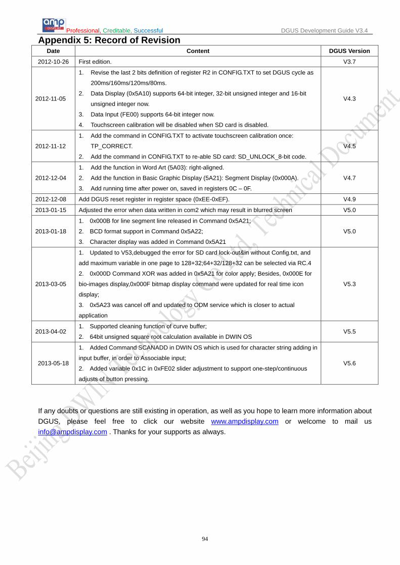
Professional, Creditable, Successful DGUS Development Guide V3.4
94
Appendix 5: Record of Revision Date Content DGUS Version
2012-10-26 First edition. V3.7
2012-11-05
1. Revise the last 2 bits definition of register R2 in CONFIG.TXT to set DGUS cycle as
200ms/160ms/120ms/80ms.
2. Data Display (0x5A10) supports 64-bit integer, 32-bit unsigned integer and 16-bit
unsigned integer now.
3. Data Input (FE00) supports 64-bit integer now.
4. Touchscreen calibration will be disabled when SD card is disabled.
V4.3
2012-11-12
1. Add the command in CONFIG.TXT to activate touchscreen calibration once:
TP_CORRECT.
2. Add the command in CONFIG.TXT to re-able SD card: SD_UNLOCK_8-bit code.
V4.5
2012-12-04
1. Add the function in Word Art (5A03): right-aligned.
2. Add the function in Basic Graphic Display (5A21): Segment Display (0x000A).
3. Add running time after power on, saved in registers 0C – 0F.
V4.7
2012-12-08 Add DGUS reset register in register space (0xEE-0xEF). V4.9
2013-01-15 Adjusted the error when data written in com2 which may result in blurred screen V5.0
2013-01-18
1. 0x000B for line segment line released in Command 0x5A21;
2. BCD format support in Command 0x5A22;
3. Character display was added in Command 0x5A21
V5.0
2013-03-05
1. Updated to V53,debugged the error for SD card lock-out&in without Config.txt, and
add maximum variable in one page to 128+32;64+32/128+32 can be selected via RC.4
2. 0x000D Command XOR was added in 0x5A21 for color apply; Besides, 0x000E for
bio-images display,0x000F bitmap display command were updated for real time icon
display;
3. 0x5A23 was cancel off and updated to ODM service which is closer to actual
application
V5.3
2013-04-02 1. Supported cleaning function of curve buffer;
2. 64bit unsigned square root calculation available in DWIN OS V5.5
2013-05-18
1. Added Command SCANADD in DWIN OS which is used for character string adding in
input buffer, in order to Associable input;
2. Added variable 0x1C in 0xFE02 slider adjustment to support one-step/continuous
adjusts of button pressing.
V5.6
If any doubts or questions are still existing in operation, as well as you hope to learn more information about DGUS, please feel free to click our website www.ampdisplay.com or welcome to mail us [email protected] . Thanks for your supports as always.