Embed Size (px)
Citation preview
CONJUGATE HEAT
From: " M a l d i s t r i b u t i o n o f F l o w & i t s E f f e c t o n H e a t E x c h a n g e r P e r f o r m a n c e , " ASME H T D - V o l . 75
- J . B . K i t t o , J r . & J.M. R o b e r t s o n , E d i t o r s . 1987
TRANSFER AND FLOW DISTRIBUTION IN AN MANIFOLDED FINNEDTUBES
0. F. Jomr Gcologicd Engin~ling
LO* Alarna National Labontory Lor Alam-. Now Mexico
N. Lior Department of Mechanical Engineering and Applied Machanb
University of Pennsylvania Philadelphia. Pennsylvania
ABSTRACT
Conjugate steady-state hea't transfer and fluld flow (Including buoyancy) In a vertical, externally Irradiated assembly of manifolded finned tubes is analyzed from fundamental prlncipleo. The assembly consists of two horizontal circular manifolds inter- connected by a number of plane-finned circular tubes. The problem has application to several types of heat exchalrgers including flat-plate solar collectors and plate heat exchangers. Buoyancy was found to tend to correct some of the flow naldistribution that would have occurred if the assembly was isothermal. by In- creasing the flow rate 111 the most flow-starved (and thus warmest) tubes. Results shovlng the influence of the main system parameters on heat exchanger flow dis- tribution, thermal performance. and pressure drop are presented. For example, for an assembly that lo cha~acteristic of a flat-plate solar collector, at least one tube was found to recdve a minimum of 15 percent less flow than average when the tubes were ioothenal.
NOMENCLATURE (for major symbols and those not deflned in text)
B dimensionless radiosity (scaled by UT~O d inside diameter g acceleratior! of gravity GP* mod1 led Gyshof nu5ber for fluid. d eerE (Tnb+~df)/(k v I h hea ttansfer coefficient h length of tubes xe dimeasionless radlant flux from high temperature.
source (T/UT~~)
5 thermal conductlvlty based on TI m mass flow rate Nu local Nusselt number (h,d /kc) n number of tubes in assekbfy -4
dimensionless fluid pressure lTc/OiU ) Fc dimension eso pressure in manifold branch reelon I v 4, ,. . .
P ' dimeds!b~?l;ss pressure in manifold "an-branch reglon ( P ' / O ~ V ~ , ~ )
ASSEMBLY OF
P* dimensionless pressure in tubes (?*/P TI, 12) aPmb dimensionless pressure drop frun fricti n and
lnertia caused by buoyancy (AP 1 0 ~ 1 ') ab 1 aPhb dimensionless hydrost tic pressure cidngr from
buoyancy (aP 10 V '1 Pr Prnndtl numbs! ok &]?id r dimensional radial coordinate in tubes (TIP ) r, tube radius
t
3 1 2 oTl c o /[kftfll-c1)1
h u ~ ~ ~ ~ ~ v ~ / [ k t (I-c 1 1 fin half wi6t6 thickness dinensionless temperature (T/Ti) dinensionless tube local axial velocity [Cl(v/r )] dimensibnless tube mean velocity (Om dimensionless tube local radlal velocity [V/(V/P I 1 dinensi6nless manifold mean velocity (Vfl,,,) length of nanlfolds local fin coordinate in fin transverse direction (see Fls. 31 ~.
X pl"bal coordinate in direction of inlet manifold flow (see Fig. 2)
r dinensionlers axial coordinate in tubes (T/r ) t
6 fin-tube bond thickness t emlonivity n dimensionless transverse cuurdlnate in fin.
(X-P ) / 8 e angufa~ position far tube Y t.12~. v kinsiktie viscosity (evaluated at T )
i I dimensionless axial coordinate (?/he) 0 fluid densitv u stephsn-~oltmann constant O dime~sl0nle8~ perturbed temperature for finned
tube. (T-T)/T.
fin hyd~oatatic Inlet manifold due to fluid notion normal beam outlet manifold radiation sink tube total
-- dimensional pressure, velocity. and temperature h high temperature source 1 low temperature source f fin
) an symbol f t tube
INTRODUCTION
we consider the problem of conjugate. steady-state heat transfer and fluid flow in a vertical, externally irradiated assembly of manifolded finned tubes as shown in Pip. 1. The assembly consists of two horlaonfsl
$for reverse flow %" mmuel-
I - q u ~ ~ s d - - - g Z J
Pip. 1. Assembly of manifold finned tubes
circular manifolds interconnected by a number of plane- finned circular tobea. A fluid is pumped into one end of the lover manifold where it is distributed through the tubes. becomes heated, and then combined in the upper nanlfold. The fluid departs the assembly in either the same direction as the inlet flow (parallel flow c o n f i g u ~ a t i o n ) OP in the oppoolte direction (reverse flow configuration). This problem has application to several types of plate heat exchangers Including flat plate solar collectors and plate heat exchangers where the inter-plate heat-transfer rate may be approximated as spatially constant.
In contrast to some of the previous manifold flow studies [cf. Bajura and Jones (1976). Bassiouni and Martin (1984a. 1984b)l the authors and their co-workers [Jones and Llor (1978). Menuchin ct al. (1981)l and Hoffman and Plannery (1985) have included both inertial and frictional effects in the manifolds. Here. flow branching occurs at discrete locations along the aanifolds with only frictional pressure loss in the non-branch reglons. This formulation results in s system of nonlinear algebraic equations that must be
solved numerically. The advsntaee of thls fornulatian is that it spans the entire range of manifold designs from inertially to frictionally dominant at the expense of l n c ~ e a s e d difficulty of salutlon. Results for Isothermal assemblies show that flow distribution becomes more uniform with decreased number of tubes (for a fixed manilold length). decreased ratio of tube diameter to nanlfold diameter, and with increased tube height-to-diameter ratio. Also. flow becomes unifornly distributed as the pressure drop in the tubes becomes the doninsnt one in the assembly.
In contrast to isothermal manifold systems, the interaction between manifold flow distribution and heat transfer to the fluid has received little attention because of its inherent complexity [Chiou (1982). Window and Hardlng (1983)l. The effect of a prescribed flow distribution pattern on thermal performance of flat plate collectors was shown to degrade efficiency by 1-20: with r e a l i o t i c c o l l e c t o r fluid-flow distributions.
ANALYSIS
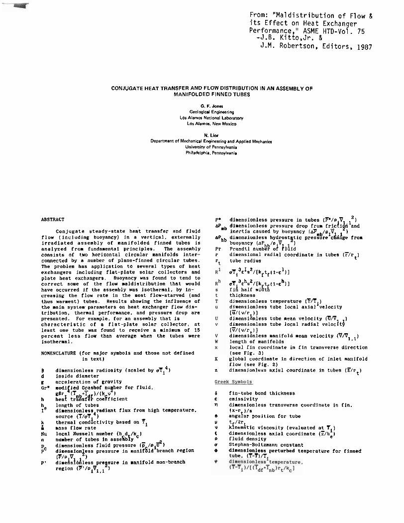
Manifold hydrodynamics. We formulate the nanlfald hydrodynamics part of the present conjugate problem assuming discrete flow branching in the manifolds. The geometry and definitions of the variables used in thin formulation are given in Pig. 2. The manifold assembly
APl.1 Pig. 2, Manifold geometry for j-th section
is divided into n increments, where n is the nunber of tubes. and manifold and tube velocities and pressure changes areidentified with each increment. Specifl- cally, A . A P ~ k. and @- refer to the pressure changes ar d ng fr 6 inertial And frictional effects in the branch region for the jth increment and the kth manifold lk-l far inlet nanifold. 2 for outlet nanifoldl. fric:i*nal effects in the non-branch region for the jth increment and the kth nanlfold, and frlc- tional effects for the jth tube respectively. Manifold and tube velocities ere V and u Referring to Pig. 2. flow to the right andJ(lbwarda Ab taken as positive
for the parallel flow confiyuratlon, and outlet- manifold flow to the left is taken as positive fur the reverse flow case.
The fluid dynamics of manifold flow are described by Keller (1949). McNown (1954). ~crlvos et al. (1959). BaJura (1971). and Bajura and j0n.s (1976). Here the dimenolanless form of the momentum and mass conservs- tion equations fur a branch in the inlet manifold are
and
respectively, where AP - P - P. The third term on the right hand'slide d'gq. (Gj.&brrects this pressure increase to account for loss of manentun from the manifold stream by the branching manifold flow. I is the ratla of the velocity in the direction of idlit-manifold flow at the entrance to the tube mouth. to the branch inlet velocity V and is termed a "static pressure regain coefflciedt!' It is determined empirically, and is a weak function of branch and nanlfold geometry, and branch-flow ratios as discussed below. A value of 1 for 7 Indicates a maximal loss of momentum in manifold fl&d whereas a value of zero corresponds to no loss of nonentum to the branching flow and the largest static pressure regain as seen from Eq. (la). The terms B are dimensionless. momentum correction factors thaC'$onvert the momentum flux based on mean velocity to that actually possessed by the flow for a prescribed flaw reglme. They are usu&lIy fired at unity for the experiments performed to obtaln the r coefficients.
A modified Bernoulli equation is written in dimensionless form to express pressure loss in a non- branch reglan
For parallel flow. the equations corresponding to Eqs. (1) and (2 ) for the outlet manifold are
In Eq. (3a). 1 is a dimensionless, empirically determined -stat26 pressure decrease coefficient" and accounts for the transport of momentum in the direction of outlet manifold flow from the combining tube stream. and momentum loss fro. turbulent mixing of the two OtPeB.8.
A modified Bernoulli equation in dlmenslonless form for the tube flow is
where c and c are emplricslly determined mechanical- C d
energy loss coefficients that account lor flow turninc in outlet and inlet ani if old branches. and f 1, an axially averaged frlctlon factor for i s ~ d e r m a l . developing flow in the tubes. APmb and AP account for presure changes arising from bdoyancy Pk'Jhe tubes attributed to fluid motion (inertial and frictional pressure drop), and the buoyant part of hydrostatic pressure change, respectively. For an isothermal assembly. AP and AP are bath zero . These terms are discusse!bld more dkkdl further below.
Since the mean pressure at any locatlon in the assembly is sincle-valued, the net pressure change around any closed loop is zero. The loop equation for parallel flow is
Equations (1-6) are a system of (1011-3) simultaneous algebraic equations for Ion pressure and velocity variables. The boundary conditiuns are
"1.1 - l. + - 0 and
V1,2 = 0 (parallel flow) or Vn+1,2 - 0 (reverse flow).
Values for the flow coefficients r r . c . and c have been emplrlcslly determined &V ncN'o& (9954) an8 Aerlvos et al. (1959).
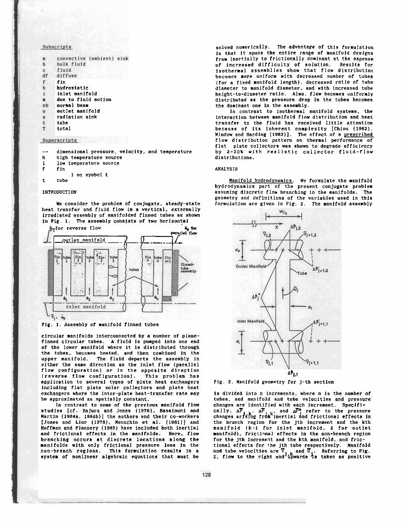
Heat transfer in the finned tubes. The finned tube geometry is s h a m in Fig. 3. To be consistent
~ i g . 3. Pinned-tube geometry for j-th section
with the manifold-hydrodynamics formulation. the assembly is dlvided into n increments correaponding to the number of tubes; each increment consisttne or a tube and the fin to its left. High temperature- source diffuse and normal-beam radiation from 'I and Tnb, and low tenperature-source radiation fro. $Em- perature T are lncfdent as the front surface of the assembly. s~onduction and radiation heat transfer occur from the jth and (j+l)st fins to the jth tube. and the tube is irradiated directly. The assembly losen heat by convection through a constant heat transfer coefflcient (h,) to tenperature Ta, by radiation outward from thedfront surface, and by conbined forced/ natural convection through variable heat transfer coefflclent (h ) to the tube fluid at bulk temperature T . For the a%alysla that follows. we assume that the tkicknrss of the bond between the fins and tubes and heat loss through the back of the assembly are negligibly small, although they may be included without much difficulty.
In contrast with previous formulations of heat t ~ a n s f e r in collectors, in particular the Hottel- Whlllier-Bliss (HWB) .ode1 (Hottel and Woertz 1942. Whllller 1953. Bliss 1859. Chlou 1959) which neglect fin/tuba radiant interaction. we include radlaat lnteractlon among sealgray (Lieblein 1959. Planondon and Landram 1966). dlffuse fin/tube surfaces in the present formulation.
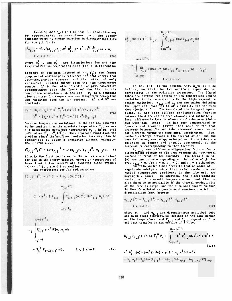
Assuming that helo >> 1 Y o that fill cullduction may be approximated a s one-dimensional, the steady constant-property energy equation in dimensionless forn for the Jth fin is
f /dn2-i2(Of,j+Pfl*~i ~ i , ~ ( n , t 1*kh B;,~(~I - 0 ,
where B and Bh are diaensionless iow and high tempera!&e-uourc!~~~adiosities for a differential
f element of fin area located at I ; the former composed of emitted plus reflected in8iddnt energy from low-temperature sources, and the latter of only reflected incident energy from the high-temperature source. l2 is the ratlo of radiative plus convective conductance from the front of the fin, to the conduction conductance in the fin. Pf is a constant dimensionless fin temperature resulting from convgctian and radiation from the fin surface. k1 and R are COnDtants.
Because temperature variations in the fin are expected to be smaller than the absolute temperature 'Ti. we use a dimensionless perturbed temperature O in Eq. (7a) defined as ( 7 -T )R . ) . This approachf dnplifies the problem sincef'&efnonfinear emission tern may then be linearized by using a truncated binomial expansion (Eno. 1976) where.
(Tf,j/~i)4 = ( I * ~ , ~ l 4 = 1 + 4 0 ~ , ~ + 0 ( 0 ~ , ~ 1 2 . 0 ~ , ~ < 1 . (81
If only the first two terms in the serien are retained for ose in the energy balance, errors in temperature of less than a feu percent are expected since typical values of O are 0.1 or smaller.
The ex6duoians for fin radiosity are
In Eq. (9). it was assumed thst h /s << 1 as before, s o that the two manifold peper do not participate io the radlation processes. The finned tubes are diffuoe reflectors of low temperature source radiation to be consistent with the high-temperature source radiation. and a are the angles defining the upper and loue:k?mits 04 visibility for the tube when viewing a fin. The kernels of the inte~ral equa- tions. K, are from dlffuse configuration factors between fin differential-area elenents and infinitely- long. differentially-wide elenents of tube area (Sotos and Stockman. 19641. It has been demonstrated by Sparrow and Krovech (1977) that most of the heat transfer between fin and tube elemental areas occurs for elements having the same axial coordinatfs. Thus. radiant exchange between a fin element at t . and two parailel tubes, can be approximated as if the tubes are infinite in length and axially isothermal. at the temperature corresponding to that location.
F are diffuse canfiguratiun factors far a differAdfPai element of fin area viewing the tsothenal surface in front of the assembly. The terms r in Eq. (91 are one or zero depending on the value of j: for j-1. = 0, and r - 1 otherwise.
Fcii+t;i::wfGe: ;ut;sf'results frod an order-of- magnitude analysis show thst axial conduction and radial temperature gradients in the tube wall are negligibly small. In addition, the circumferential variation of tube-wall temperature and heat flux is also shown to be negligible if the thermal conductivity of the tube is is~ge. and the tube-wall energy balance is thus formulated as quasi-one dinansional, which. in dimensionless forn. becones
where O and @ are dimensionless perturbed tube and bulJ.liuid te%bdratures defined in the sane manner as flrt temperature. and P and lt depend on flow and heat transfer in and oukdide of a'dube.
r, JB:.,(e.tf~~(ej.nj)de n-~i"-l~
t 3 1 wtnj Pt,j(t I= (r Ti rt [ I +
aj(n)
4 (lla) Ts E ( f 4 1 , j ( ~ ~ ' ~
1 < j <n+l. (gal ch ~:,~(e)/(1-0~1) do] + o T~~ ap c'/(~-c')
where a = rt(n-2sin-1ul is the perimeter of the top alde of 'a tube. In ~ g . (lo), the tube-wall temperature 1% a linear function of the bulk fluid temperature. 1 IS the ratio of the convective conductance between t 6 3 tube wall and the fluid, to the sun of all conductances from the tube to the external radiative and convective sinks and to the fluid. The term P is a dimensionless stagnation temperature for the t6nd which occurs for Nu equal to zero (or no fluid flow).
Rsdiosity disdibutions for the tubes are written In the sane way as for the fins in Eq. (9) but are not Presented here for brevity. In this case, radiant contributions to a differential element of tube area are from the adjacent tube and fin that view it, and the radiant sink temperature or high temperature source as before.
The finned tubes are insulated along the outer edger. The remaining boundary condition is a matching of the fin and tube tenperature where they are in contact. Thus. temperature continuity is satisfied acros9 the fin and tube interface, and Eq. (11) satisfies continuity of heat flow there.
Pluid flow and heat transfer in a tube. The configu?ation considered is upward flaw of a Boussinesq fluid in n externally vertical circular tubes of length h and radius rt, which, equally spaced. connect an lalet manifold to an outlet manifold. The radial and ~~ ~~~~~~ ~~~ ~~~~ ~ ~~~-
axial direction and velocity components arc denoted as tT.71 and lB.iil, respectively. The mean velocity at the inlet to each tube is 3 . and the inlet temperature for all tubes is T . WJ predict the pressure and temperature distribution for each tube and couple this information to the parts of the problem that treat flnned-tube heat transfer and manifold hydrodynamics. In thio way. mass. momentum, and energy conservation fpr theentlre assembly are satisfied simultaneously. As an example of thio coupline. heat transfer to a particular tube infuences the tube friction factor which affects a change in the tube fluid flow rate and. in turn, alters the rate of heat transfer from the orieinal value.
The topic of developing, buoyancy-assisted coabined convection in a vertical tube has received considerable attention in the past. The studies performed considered either constant temperature (Zeldin and Schmidt 1972. Marner and Mcnillan 1970. Lamence and Chato. 1966). or constant heat flux tube walls (Zeldin and Schmidt 1972. Lawrence and Chato 19661. Because the more realistic conjugate problem is belng solved in this study, neither of these conditions may be imposed: rather siaultaneous solution of the problem coupling all subsystems is executed. As is ofteo the case for flow in compact and plate heat exchangers having smooth and small flow passages, and relatively low velocity. it in assumed that the flow is laminar. The inlet velocity to each tube is taken to be uniform. After an entry length (of about 10 tube diameters for the cases considered here) the radial pressure gradient is negligibleL In the usual m y , the axial pressure gradient (d? /dz) is expressed as the sum o f two independent $reosure gradients: one attributed to fluid motion and the other arising from hydrostatics:
where dc /dT = -Otg, and is referenced to tube-wall h temperature. With D - 0 [I + 8 (Ti -c)]. where B 1s the coefficient of tfer.a+ expansion.
Since Convective acceleration is small for this case, the axial component of the nolaentun equation using Eqs. (12) and (13) is
G m / d i - -oig B (Tt - Tc) + [VISCOUS terms]. (14)
In Eq. (14). the temperature difference term is positive and the viscous terms are negative. so we see that the effect of buoyancy on the flow is to increase the axial pressure gradient dFm/di relative to that in the isothermal case.
The total pressure gradient is now written froa Eqs. (12)-(14)
d? /dZ=-oig B(T -7 1 [viscous terms1 C t C
The first two terms on the right-hand side of Eq. (IS) represent the contribution froa fluid motion (d: /di), and the third and fourth terms are the buo?ant and isothermal contributions from hydrostatics respectively. The fourth term is 2-3 orders of magnitude smaller than the rest and for this reason it will he neglected. The first and third terms in Eq. (15) combine to form a single positive-valued buoyancy tern (because T > Ti) and since the viscous term are negative, thecoverall effect of buoyancy on forced upward flow in an isolated, externally heated tube is to reduce the total Pressure qradient relative to the isothermal care. This is equivalent to a reduction in tube friction factor when conpared with that for isothermal flow. It is this effect that causes an increased tube flow rate with tube-wail temperature as cited in the example above. Compared with isothermal conditions, the partially flow-starved land thus warmest) tuber in the assembly exhlkit a reduced flow resistance compared with cooler tubes and, hence, an increase in fluid flow rate -when bubyancy effects exist.
Past numerical i'tudies of assisting combined convection in an inclined tube (Cheng and Hong 197Za. 1972b) have shown that local friction factors and Nusselt numbers are independent of Prandtl number and increase nonotonically with angle of inclination from the horizontal, till a vertical orientation is reached. Increased local heat transfer lo the tubes increases performance of the assembly directly, and also indirectly through more uniform flow distribution as discussed above. It follows then that solutions of the present problem, which treats vertical tubes, represent an upper bound on improvement in thermal performance over the isothermal ease. ~~ ~ -- - ~~
Based on the preceding developments. the following is to be used with Eq. ( 5 )
where the first term In parenthesis in Eq. (16b) accounts for the actual pressure gradlent for a tube having an externally heated wall, and the second one is the pressure eradient occurring for the sane hydro- dynamic conditions if the flow is Isothermal.
Por the case where the Peclet number for tube flow 1. greater than 100. so that axlal momentum and heat transport ape neglected, the equatlons governing mass. momentum. and energy conservation in dlnensionlevs form for the flow in each tube are
In Eqs. (17a)-(17d). the velocity components. prysure. and coordinates are scaled wlth u/rt oi(u/rt) , and rt. respectively. The boundary condltions are
where Pr is the Prandtl nunber. Re is the tube Reynolds number. and or* is a modified Grashof number.
Thls part of the conjugate problem Is coupled to the remaining two parts through the buoyancy term in Eq. Il7c) where the tube-wall temperature affects the velocity and temperature fields for the fluld In each tube. and through the boundary conditon at the tube entrance where the tube Reynolds numbers result froa manlfold hydrodynamics.
WETHOD OF SOLUTION
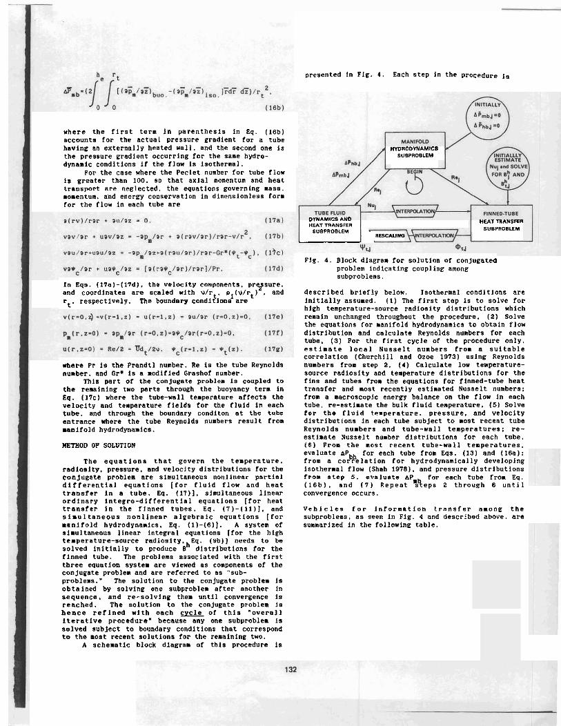
The equations that govern the temperature. radiosity, pressure, and veloclty dlstrlbutions for the conjugate problem are slnultaneouo nonlinear partial differential equations [far fluid flow and heat transfer in a tube. Eq. (17)l. simultaneous linear o r d i n a ~ y lntegro-differential equations [for heat transfer in the flnned tubes. Eq. (7)-(ll)], and simu 1 tanenus n o n l i n e a ~ aleebralc equatlons [far manifold hydrodyna.1~~. Eq. (1)-(6)l. A system of simultaneous llnear Integral equations [for the high temperature-source radia~lty.~Eq. (Yb)] needs to be solved initially to produce B dlstributions for the finned tube. The problems associated with the flrst three equatlon system are viewed as components of the conjupate problem and are referred to as 'sub- problems.' The solutlon to the conjugate problem is obtalned by solvine one subproblem after another In sequence, and re-solving them until convergence 1s reached. The solutlon to the conjugate problea is b e n c e refined wlth each c& of this "overall iterative procedure' because any one subproblem Is solved subject to boundary conditions that correspond to the moot recent solutions for the remainlne two.
A schematic black diagram of this procedure is
oresenfed In Pig. 4. Each step In the procedure is
HmROOVNAMICS SUBPROBLEM
DYNAMICS AND HEAT TAANBIER
HEAT TIANSFEI
SUBPROBLEM SUBPROBLLM RESCAUNO -
Pig. 4. Block diagram for solution of conjugated problem Indlcating coupling among subproblems.
described brlefly below, Isothermal candltlans are Initially assumed. (I) The flrst step is to solve for hieh tenperature-source radiosity distributions which remain unchanged throughout the procedure. (2) Solve the equations for manifold hydrodynamics to obtain flow distribution and calculate Reynolds numbers for each tube. (3) For the first cycle of the procedure only. eatimatc local Nusselt numbers from a suitable correlation (Churchill and Ozoe 1973) uslng Reynolds numbers from step 2. (4) Calculate lo* temperature- souPce radioslty and temperature dlstrlbutlons far the fins and tubes from the equations for finned-tube heat transfer and most recently estimated Nusselt numbers; froa a macroscopic energy balance on the flow In each tube. re-estimate the bulk fluld temperature. ( 5 ) Solve o r the fluid temperature. pressure, and velocity dlstributions in each tube subject to most recent tube Reynolds numbers and tube-wall temperatures: re- estimate Nusselt number distributions for each tube. ( 6 ) From the most recent tube-wall temperatures. evaluate &Pbh for each tube from Eqs. (13) and (16a): from a correlstlon for hydrodynamically developing Isothermal flow (Shah 1978). and pressure dlstrlbutions from atep 5. evaluate AP for each tube from Eq. (16b). and ( 7 ) Repeat S e p s 2 through 6 until convergence occurs.
V c h l c l e s f o r informatlon transfer anone the subproblens. as seen in Flg. 4 and described above. are summarized in the following table.
Vehfcles fop information Transfer Amone the Subproblems Hanlfold Flnned-tube Fluid
Hvdrodynamlcs Heat Transfer Dynamics and Heat Transfer in n Tube
Manlfold -- Re 1
Rej. Hydrodynamics
APnb.j'
Pinned-tube -- Heat Transfer + t . ~ .
(or *t,j).
NU J I.ocal Nusselt numbers have been used in the part as vehicles far inforlnatlon transfer between parts of a conjugate problem by Sparrow and Faghri (1980). and they work well.
The manifold-hydrodynamics subproblem was solved by the Newton-Raphson method which used Choleski decomposition (for parallel flow cases1 or Gauss-Jordan reduction (for reverse flaw). Convergence was achieved when all equations were satisfied to within a dimensionless velocity and pressure change of The equations for finned-tube heat transfer were solved by flnite differences using 11 nodes for the fin in the transverse direction and for the tube in the circumferential direction. Five-point backward or forward differences were used for the temperature gradlento in Eq. (llal. The kernel functions and configuration factors in the radiosity integral equations were evaluated for all fin- and tube-node ~ombinat10ns. Because of the sensitivity of the kernels and configuration factors to slight changes in coordinate values in the neighborhood of the fin/tube interfaces. the nodes nearest to the interfaces were sub-divided into 10 finer nodes and the kernels and configuration factors were calculated for these and then averaged. Integral equations were approxinsted by a sixth-order Simpson's rule wlth fourth-order end correctfons. The system of linear algebraic equations -4 solved by Gauss-Seldel iterstlon using a relative convergence criterion of lo-'. The radiosity integral equations for the high temperature-source were approximated in the sene way and solved by iteration where convergence was schleved when all equations were satisfled to within 10- dlmensionleso radiosity units.
The equations for fluid flow and heat transfer In the tubes were solved by flnite differcences using a flne axial-dlrectlon mesh in the region near the tube mouth and a coarser mesh downstream Iron this. Typically. 41 radial and flrst-region axlal nodes were used with 31 second-region axlal nodes. Upwind differences were used far axial convection and central differences far the diffusion term*. Theequations were solved lnplicitly by marching in the downstream direction, solving far velocity, pressure, and temperature at a11 radial nodes for each step of the march. A sparse-coefficient, linear algebraic equation solver (Gupta and Tanjl 1977). which employs matrix de~~mposftion. wan used to solve the system of linear algebraic equations at each axial location.
Only about three of four cycles were required to cenvepge the "overall iterative procedure". described in Fig. 4, except for several cases with large tube diaaeters which required slx or seven cycles because of
the atronger affects from buoyancy. Typical runnlng time on an IBM 4341 computer was nbout 1250 seconds for an asscnbly of four tubes, whlch converged in four cycles.
RESULTS AND DISCUSSION
B e c a u s e the principal focus is on flow dlstributlon, tube diameter and tube length were selected as primary paraaeters since these not only affect flow dist~ibution far an isothermal assembly but also influence heat transfer to the tube fluid (throueh Gr* and flow development considerational. The analysis was also performed for parallel and reverse flow configurations. It has been shown by Jones and Lior (19781 that nearly uniform flow conditions exlst far d id I d /d 1 of 0.25 and smaller, and so we take this a& tie ]$we? bound for d A reasonable upper bound was assumed to be dt/di J'0.75. The speclfic example for which this analysis was used concerned flat plate so1.a~ ~ o l l e c t o r s which typically have manifold diameters of about 1.27 cm and tube lengths of 1 to 2 m . TO Investigate the effect of tube length on flow distribution and perfornance, we choose two values for tube length: 0.61 n ("short aosembly"). and 1.83 n f"1ong assembly"). The remaining varlables are fixed at the values as shorn below.
c1 - 0.2 ch = 0.8 fluid: water
Pour tubes (risers) ware chosen for computational convenience. The expected results for assemblies having more than four tubes are briefly discussed below.
To address the effect of buoyancy on flou distribution and assembly performance, two limitiny cases were considered: one with and one without buoyancy effects. The solutlon of the conjugate problem is thus obtained for 24 different conbinatlons of varlables: three diameter ratios for short and long assemblie8 for both upper- and lower-bound cases. and far parallel and reverse flow.
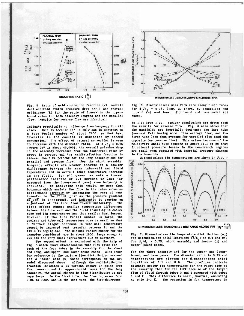
The influence of buoyancy on flow dlstribution. overall preooure drop, and thermal performance for all 24 combinations 1s presented in Plg. 5 where ratios of these quantities arc plotted for the lover-(1) and upper-(") bound cases against dlameter ratio. AP is the total dimensi nleoo pressure drop for the assesbly (scaled by plVl 14) less 1-0 gh as discussed above. The thermal pdrformance. . 5 s the ratio of the instantaneous heat transfer to the fluid. to the total irradiance on the surface of the assembly. The variable r la a dimensionless flaw naldistribution fraction defined as
* = - ;minl/+/n) (18)
where the denominator 1s the mass flow rate per tube for uniformly distributed flow, r: is the difference between the maximal and minimal dimensionless mass flou for the tubea. K - 0 indicates uniform flow d i s t r i b u t i o n . whereas a nonzero value shows naldlstrihuted tobe flaw: larger values indlcsting larger maldistrfbution.
Referring to Fig. 5 , the reaults for d /dl-0.251 (where the flow dlstribution is approximatel$ uniform)
PARALLEL FLOW PARALLEL FLOW '.* I. hn. .... mw . t i low .... rnbh 1
dt DIAMETER RATIO
Pig. 5. Ratio of maldistribution fraction ( K ) , overall dual-manifold system pressure drop (AP I and thermal
T efficiency (E) for the ratio of lower- to the upper- b o u ~ d cases for both assembly lengths and for parallel flow. Results for reverse flow are identical.
indlcate practically no influence from buoyancy for all cases. Thin is because Gr* 1s only 556 in contrast to a tube Peclet nunber of about 7200. so that heat transfer to the coolant is donlnated by forced convection. The effect of natural convection is seen to Increase with the diameter ratio. At dt/dl = 0.75 (here Or* is about 45.000). the overall pressure drop In the assenbly decreases from the isothermal value by about 38 percent and the maldlstribution fractlon is reduced about 24 percent for the long assembly and for parallel and reverse flow. @or the short assembly. buoyancy effects are weaker because of a smaller difference between the mean tube-wall and fluid teperatures and an overall lower temperature increase ln the fluid. For all cases. we note a thermal performance Increase of 0.4 percent or less (as measured from the lower-bound case) when buoyancy is included. In analyzing this result. re note that buoyancy whlch assists the flow in the tubes enhances performance dlrectly by increasing the rate of heat transfer to the fluid (just as the pressure gradient d 6 /dT la increased). and Indirect1 by causing an adyustment of the tube flow toward uYniformlty. The first effect causes smaller temperature differences between the tube wall and the fluid resulting in cooler tube and fin temperatures and thus smaller heat losses. However, If the tube Peclet nunber is large, the coolant and tube-wall temperature rise is snall so that a further slight decrease in tube-wall temperature caused by improved heat transfer between it and the fluld l o negligible. The minimal Peclet number for the examples considered here is about 1600. large enough to explain the very small improvement due to buoyancy.
The second effect is explained with the help of Pig. 6 which shows dimensionless tube flow rates far each of the four tubes in the assembly far the short and long, and upper- and lower-bound cases. Also shorn for reference is the unlform flow distribution assumed for s "base" case (b) which corresponds to the HUB model discussed above. Although the maldlstribution fraction indicates a 24 percent change in going from the lower-bound to upper-bound cases for the long assembly, the actual change in flow dlstrlbution 1s not very large. In the first tube, the flow increases from 0.85 to 0.90. and in the last tube, the flow decreases
DIMENSIONLESS DISTANCE ALONG MANIFOLDS IXIW!
Pig. 6. Dlnensionlens mass flow rate among rloer tubes for dt/d = 0.75. long, 2 . short, s. assenblles and upper- h) and lower- (L) bound and base-model (b) Cases.
to 1.16 from 1.20. Similar conclusions are d r a m Iron the results for reverse flow. Pig. 8 also shows that the manifolds are inertially dominant; the last tube (nearest X-1) havlng more than average flow, and the first tube less than average for parallel flow (and the opposite for reverse flow). This arlses because of the relatively snall tube spacing of about 11.1 cn so that frictional pressure losses in the "an-branch regions are small when compared with Inertial pressure changes In the branches.
Dlnensionlesa fin temperatures are shorn in Pig. 7
Xi-'t DIMENSIONLESS TRANSVERSE DISTANCE ALONG FIN h =
Pig. 7. Dimensionless fln temperature dlstributlon ( O ) for dimensionless axial locations (?/h ) of 0.1 and 0'9 for d /dl - 0.75. short assembly an$ lower- ( 2 ) and upperf bound cases.
for the short assembly and for the upper- and lower- bound. and base cases. The diameter ratio la 0.75 and temperatures a r e plotted for diaensionless axlal locations of 0.1 and 0.9. The profiles indicate slightly cooler fln temperatures for the right slde of the assembly than for the left because of the larger flow of fluld through tubes 3 and 4 compared wlth tubes 1 and 2. Thla difference la small, however, amounting to only 2-3 K. The reduction in fin temperature in
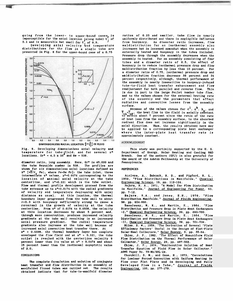
colng from the lower- to upper-bound casesf Is Inperceptlble for the axlal locatlon plong tube) t of 0.1 and is measurable but small f n ~ r "r n o J
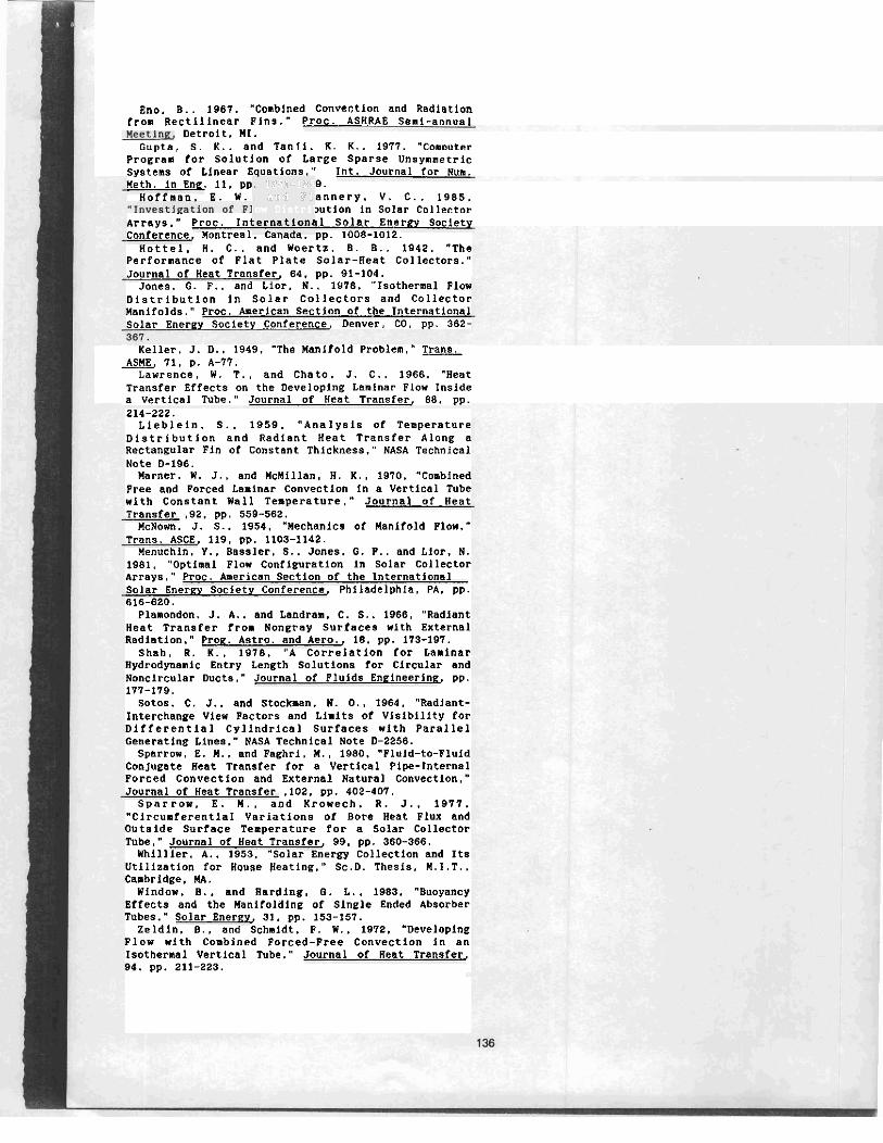
~ -.- .-. Developlng axlal velocl ty '4;; -L;nperature
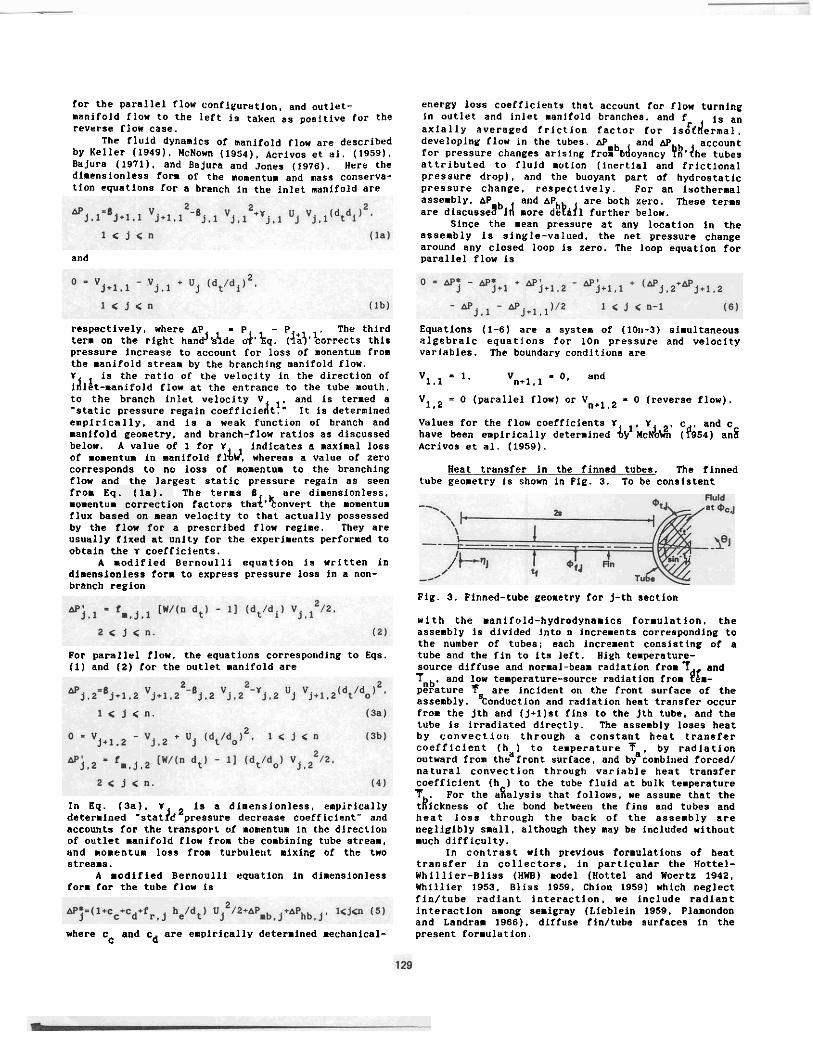
distrlbutlons for the flow In a slnglr tube are presented In PIC. 8 for the upper-bound case of a 0.75
~ a t l o s of 0.25 and smaller. tube flaw 1s nearly uniformly dlstrlbuted and there is negligible Influence from buoyancy. An dlameter ratla increases. flow maldlstrlbution for an isothermal assembly also Increases but is lessened somewhat when the assembly is externally heated and buoyancy in the tubes Included. Pressure drop through the assembly decreases when the assembly Is heated. For an assembly consisting of four tubes and a dlameter ratlo of 0.5, the effect of buoyancy lo to reduce loothermal pressure drop and flow aaldlstrlbutlon fraction by less than 10 percent. Par a diameter ratio of 0.75. lsothernal pressure drop and maldistrlbutlon fraction decrease 38 percent and 24 percent respectively, although, thermal performance of the assembly 1s nearly lnsensltive to buoyancy-Induced tube-to-fluld heat transfer enhancement and flow readjustment for both parallel and reverse flow. This IS due In part to the large Peclet number tube flaw. and to the values chosen for the external heating rate of the assembly and the parameters that effect radiative and convectlve lasses from the assembly surface.
1 h Because of the values chosen for c . o . h . and i , the heat flux to the fluid is axlally cosstant
t 8 b w ~ q 6 ~ n about 7 percent slnce the ratlo of the rate of heat loss from the assembly surface, to the absorbed radlant flux doer not increase slgnlficantly in the axla1 direction. Thus, the results obtalned here nay be applied to a corresponding plate heat exchanger w h e r e the inter-plate heat transfer rate lo approximately Constant.
DIMENSIONLESS RADIAL LOCATION [?.+I IN FLUID
Plg. 8. Developlng dimensionless axlal veloclty and temperature for tube-fluld. and for several r* locations. Or* = 4.5 x 10 and Re - 538. dlameter ratlo. long asseably. Here. Or* is 45.000 and the tube Reynolds number la 538. The proflles are shorn for six dlmenslonless axial lacatlons deflned as z* [-?/P Pel, where Pe-Re Prl: the tube inlet. three internedfate r* values. z*-0.0174 corresponding to the location of naxlmal axlal velocity at the tube centerllne. and E*-0.121 whlch lo the tube outlet. Plow and thermal proflle develovment proceed from the
Thls study was partially supported by the U. S. Department of Energy. Solar Heating and Coollng RID Branch. One of the authors (GFJ) Is also grateful far the award of the Ashton Pellowohip at the Unlverslty of Pennsylvania.
REFERENCES
ACrIV08. A,. nabcock. 8. D.. and Plgford. R. L.. 1959. "Flow D1strlbutlons In Manifolds." Chenlcal Enelneerlne Sclence. 10. p p 112-124.
Baiurs. R. A,. 1971. "A Model for Plow Dlstrlbution tube entrance up tb z*-0.0174 wlkh the-radial gradlents in ~nifolds." Journal of Enelneering for Power. 93. of velocity and tenverature decreaslna wlth axial DD. 7-12. distance as usual. At thls location,-the thermal boundary layer progressed from the tube wall to about 1-0.3 with buoyancy sufflclently strong to cause a reversal In the growth of veloclty at the tube centerllne. From z* of 0.0174 to 0.0508. the velocity at thl8 location decreases by about 5 percent and. through mass conservetlon, produces Increased velocity eradiento at the tube wall resulting in an increased axial pressure gradlent. The radial temperature gradlents also Increase at the tube wall because of Increased sxlal convectlve heat transfer there. At Z* - 0.0508. the thermal boundary layer has complete enveloped the flou field and at 2' = 0.121. the tube outlet Is reached with the centerllne velocity 9 percent laver than its value at 2' = 0.0174 and about 15 percent lower than the Isothermal asymptotic value of 2.0.
CONCLUSIONS
The complete formulation and solutlon of conjugate heat transfer and flou dlstrlbutlon in an assembly of manifolded flnned tubes was carrled out. The results abtalned indicate that for tube-to-manifold diameter
. . Bajura. R.A.. and Jones. E.H., 1976. '"Plow
Dlstributlon Manifolds." Journal of Plulds Englneerlng. 98. pp. 654-666.
Basslouny. W . K.. and Martin. H.. 1984. "Flow Dlstributlon and Pressure Drop in Plate Heat Exchangers - I . " C C ! 39, pp. 693-700.
Baonlouny. M. K.. and Martln. H.. 1984. "Plow Distrlbutlon and Pressure Drop in Plate Heat Exchangers -11. Chenlcal Enelneerlna Sclence, 39, pp. 701-704. B11ss. R. W . . 1959. 'The Derivation of Several 'Plate
Efflciency Pactors' Useful in the Design of Plat-Plate Solar-Heat Collectors." Solar Energy, 3. pp. 55-64.
Chlou. J. P . . 1982. '"The Effect of Nanunlform Fluid Flow Dlstrlbution on the Thermal Perfornancc of Solar Collector." solar Energy, 29. pp. 487-502.
Chlou. J. P.. 1979. "Nonlteratlve Solution of Heat Transfe~ Equatlon of Fluid Plow in Solar Collector." ASHE Paper No. 79-WA/SOL-24.
Churchill. S. W . . and Ozoe. H.. 1973, "Correlations for Lamlnar Forced Canvectlon wlth Uniform Heating in Plow over Plat Plate and in Developlng and Fully Developed Flow in a Tube." Journal of Flulds Enelneerink 100. PP. 177-119.
Pno. B.. 1967. ''Conblned ConveCtlon and Radlatlon . -
f r o ~ectlllnear Plnr." Proc. ASHRAE Senl-annual Detroit. MI.
Guota. S. K.. and Tanll. K. K.. 1977. "Cornouter . . Praeraa for Solutlon of Laree Sparse Unsvmnetric . . syo&ns of Llnear Eaustions:' Int. Journal >or ~ u n ; Ueth. in Eng. 11, pp 9.
Hoffman. E. W. a n n e r ~ . V. C.. 1985. . 1251-125 . and PI low Distril :ernatlone
,.---A-
,utlon~in Solar Collector . Arrays." Proc. Inl 11 solar en erg^ Soclety Conference. Uontreal. r a ~ ~ ~ u ~ . pp. 1008-1012.
Hottel. H . C.. and Woertz. B. B.. 1942. "The Performance of Plat Plate Solar-Heat Collectors." Journal of Heat Transfer, 64, PP. 91-104.
Jones. G. F.. and Lior. N.. 1976. "Isothermal Flow ~ i s t r l b u t l o n in Solar Collectors and Collector Manifolds." Proc. American Section of the International Solar Enerey Soclety Conference. Denver, CO. pp. 362-
Keller. J. 0.. 1949. "The Manifold Problem.'' Trans. ASIE. 71. p. A-77.
Lawrence. W. T.. and Chsta. J. C.. 1966. "Heat Transfer Effects on the Developing Laminar Flow Inside a Vertical Tube." Journal of Heat Transfer, 68, pp. 214-222.
Lleblein. S.. 1959. "Analysis of Temperature Dlstrlbutlon and Radlant Heat Transfer Along a Rectangular Fin of Constant Thickness." NASA Technical Note D-196. Marner. Y . J.. and KcMlllan. H. K.. 1970. "Conblned
Free and Forced Laminar Convection in a Vertical Tube with Constant Wall Temperature." Journal of Heat Transfer .92. pp. 559-562. UcNom. J. S.. 1954. "Mechanics of Uanlfold Plow."
Trans. ASCE, 119, pp. 1103-1142. Uenuchin. Y.. Bassler. S.. Jones. 0 . P.. and Liar. N.
1961. "Optimal Plow Conflpurstion in Solar Collector A ~ ~ Y S . " PPOC. American Section of the International Solar Enerey Society Conference. Philadelphia. PA, pp. 616-620.
Plamondon. J. A.. and Landram. C. S.. 1968. "Radiant Heat Transfer from Nongray Surfaces with External Radiation.* Proe. Astro. and Aero., 18. pp. 173-197.
Shah. R. K.. 1978. "A Correlation for Laminar Hydrodynanlc Entry Length Solutions for Circular and Nonclrcular Ducts." Journal of Fluids Enclneerln& PP. 177-179.
Sotos. C. J.. and Stockmen. N. 0 . . 1964. "Radlant- Interchance Vier Pactoro and Llmits of Vlsiblllty for Differential Cyllndrical Surfaces with Parallel Generating Lines.'' NASA Technlcal Note 0-2256.
Sparrow. E. K.. and Paghri, U.. 1980, "Pluid-to-Fluid Conjugate Heat Transfer for a Vertical Pipe-Internal Forced Convectfen and External Natural Convection." Jou~na1 of Heat Transfer .102. pp. 402-401. S P B ~ P O X . E. K.. and Krowech. R. J.. 1977.
"Clrcumferentlal Variations of Bore Heat Flux and Outside Surface Temperature for a Salar Collector Tube." Journal of Heat Transfer, 99. pp. 360-366. Whlllier. A,. 1953. "Solar Energy Collection and Its
utiliratlon for noupe Besting." Sc.0. Thesls. M.I.T.. Cambridge. MAV\.
Window. B.. and Hsrdlng. 0. L.. 1983. "Buoyancy Effects and the Manlfalding of Single Ended Absorber Tubes." Solar Enerey, 31, pp. 153-157.
Zeldin. 8.. and Schaldt. P. 1.. 1872. "Developing P l o w with Comblned Porced-Free Convection in an Isothermal Vertical Tube.' Journal of Heat Transfer. 94. pp. 211-223.