Embed Size (px)
Citation preview
DG Series User Manual 1
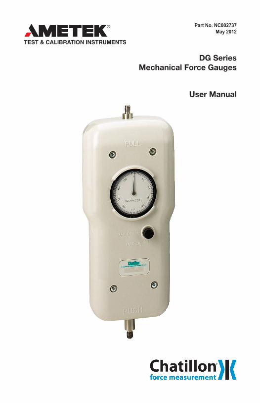
Part No. NC002737May 2012
DG SeriesMechanical Force Gauges
User Manual
2 DG Series User Manual
WARRANTYThis instrument is warranted against defects in workmanship, material and design for two (2) years from date of delivery to the extent that AMETEK will, at its sole option, repair or replace the instrument or any part thereof which is defective, provided, however, that this warranty shall not apply to instru-ments subjected to tampering or, abuse, or exposed to highly corrosive conditions.
THIS WARRANTY IS IN LIEU OF ALL OTHER WARRANTIES WHETHER EXPRESS OR IMPLIED AND AMETEK HEREBY DISCLAIMS ALL OTHER WARRANTIES, INCLUDING, WITHOUT LIMITATION, ANY WARRANTY OF FITNESS FOR A PARTICULAR PURPOSE OR MERCHANTABILITY. AMETEK SHALL NOT BE LIABLE FOR ANY INCIDENTAL OR CONSEQUENTIAL DAMAGES, INCLUDING, BUT NOT LIMITED TO, ANY ANTICIPATED OR LOST PROFITS.
This warranty is voidable if the purchaser fails to follow any and all instructions, warnings or cautions in the instrument’s Instruction Manual.
If a manufacturing defect is found, AMETEK will replace or repair the instrument or replace any defective part thereof without charge; however, AMETEK’s obligation hereunder does not include the cost of trans-portation, which must be borne by the customer. AMETEK assumes no responsibility for damage in transit, and any claims for such damage should be presented to the carrier by the purchaser.
TRADEMARKSAMETEK is a registered trademarks of AMETEK, Inc.CHATILLON is a registered trademark of AMETEK, Inc.Other trademarks are the property of their respective owners.
SUPPORTAMETEK Measurement & Calibration Technologies8600 Somerset DriveLargo, FL 33773United States of America
Tel: +1 800 527 9999 (toll free within continental U.S.A.)Tel: +1 727 536 7831Fax: +1 727 539 6882Email: [email protected]: www.chatillon.com
DG Series User Manual 3
ICoNs
WARNINGThe raised hand icon warns of a situation or condition that may lead to personal injury or death. Do not proceed until the warning is read and thoroughly understood. Warning messages are shown in bold type.
DANGERoUs VoLTAGEThe lightning icon warns of the presence of an uninsulated dangerous voltage within theproductenclosurethatmightbeofsufficientmagnitudetocauseseriousshocksordeath.NeveropentheenclosuresunlessyouareanauthorizedandqualifiedCHATILLON service personnel. Never open any enclosure when power is connected to the system or its components.
CAUTIoNThe exclamation point icon indicates a situation or condition that may lead to equip-ment malfunction or damage. Do not proceed until the caution message is read and thoroughly understood. Caution messages are shown in bold type.
NoTEThe note icon indicates additional or supplementary information about the action, activity or concept. Notes are shown in bold type.
CAUTIoN
HIGH FoRCEs ARE oFTEN INVoLVED WITH THE MATERIAL TEsTING PRoCEssEs.
IF THE EQUIPMENT Is UsED IN A MANoR NoT sPECIFIED BY THE MANUFACTURER, THE PRoTECTIoN PRoVIDED BY THE EQUIPMENT MAY BE IMPAIRED.
To MAINTAIN ALL AsPECTs oF THE sPECIFICATIoN, oNLY AMETEK APPRoVED ACCEssoRIEs, CoNNECTIoNs AND CoMPoNENTs sHoULD BE UsED.
sTRICTLY ADHERE To ALL sPECIFIED sAFETY PRoCEDUREs
READ THIs MANUAL BEFoRE UsING THIs PRoDUCT.
General safetyGeneral safety precautions must be followed when using this CHATILLON product. Failure to observe precautions and warnings may result in damage to the equipment, or injury to personnel.
It is understood that safety rules within companies vary.Ifaconflictexistsbetweenthematerialcontained in all CHATILLON User’s Guides and the rules of a company using a CHATILLON product, the more stringent rules should take precedence.
safety ConsiderationsThe DG Series is completely enclosed and pro-vides no potentially hazardous outputs.
Mechanical components housed within the DG Series covers are to be serviced by authorized CHATILLON representatives only.
Whendesigningacustomfixtureensuretheloadratingofthecustomfixtureex-ceeds the load rating of the force gauge. i.e. If the load rating of the force gauge
is500LBFthecustomfixtureshouldhavealoadrating greater than 500 LBF
4 DG Series User Manual
iNTRODUcTiON The DG Series mechanical force gauge is ideal for a wide range of force testing applications. Based on our popular DPPH Series force gauge, the DG Series features a 2.25-inch dial for improved resolution and readability, peak hold button, ergonomic shape and improved accuracy of +0.5% of full scale. The DG gauge is an excellent, economical solution for tensile or compression testing.
The DG series gauge can be used as a hand held device with a handle adapter assembly that can be purchased separately. Gauges may be mounted to a test stand for even greater control and consistent results in repetitive testing applications. Easy to read concentric dial measures clockwise direction only. Dial rotates 360-degrees for taring. A peak hold button captures peak readings. Available in lbf, kgf or N units of measure. DG Series gauges come complete with protective carrying case and a set of stainless steelattachments.ACertificateofCalibrationwithDataissuppliedstandard.
OPERATiONThe zero point of the gauge may not always be in the 12 o’clock position due to gravity effects and the weightoffixturesorgripsontheforcegaugeshaft.Tozerothegauge,rotatethebezelonthedialindicatorso that the indicator pointer lines up with the zero on the dial face.
Gauges are designed for axial loading. Ensure the load is not applied at an angle or an error can be introducedintheforcereadings.Thegaugesaredesignedtohavea10%tareforfixturesandgrips.Ifthis 10% tare is exceeded, the force gauge may not measure up to full scale.
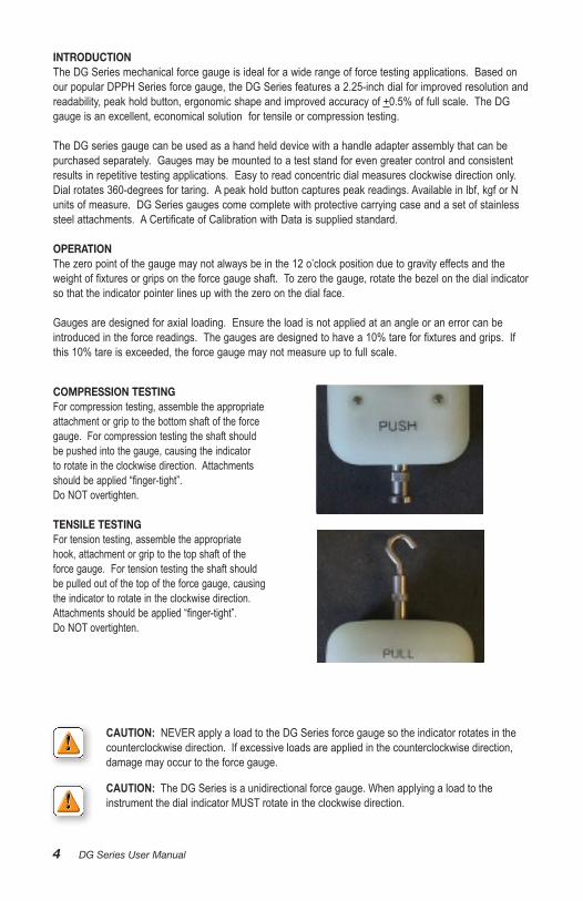
cOMPRESSiON TESTiNGFor compression testing, assemble the appropriate attachment or grip to the bottom shaft of the force gauge. For compression testing the shaft should be pushed into the gauge, causing the indicator to rotate in the clockwise direction. Attachments shouldbeapplied“finger-tight”. Do NOT overtighten.
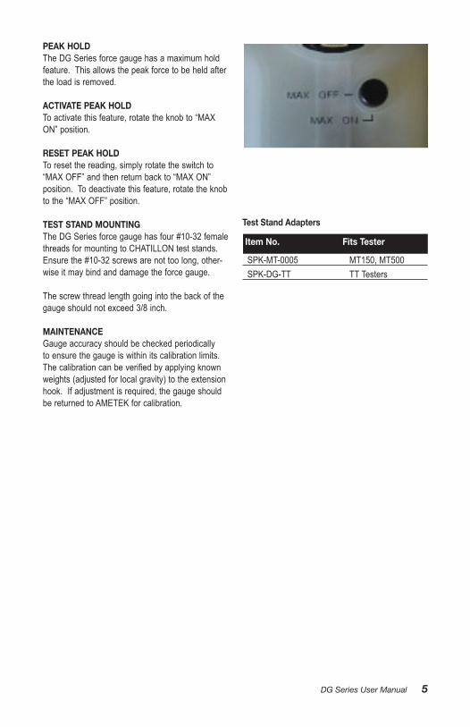
TENSilE TESTiNGFor tension testing, assemble the appropriate hook, attachment or grip to the top shaft of the force gauge. For tension testing the shaft should be pulled out of the top of the force gauge, causing the indicator to rotate in the clockwise direction. Attachmentsshouldbeapplied“finger-tight”. Do NOT overtighten.
CAUTIoN: The DG Series is a unidirectional force gauge. When applying a load to the instrument the dial indicator MUST rotate in the clockwise direction.
CAUTIoN: NEVER apply a load to the DG Series force gauge so the indicator rotates in the counterclockwise direction. If excessive loads are applied in the counterclockwise direction, damage may occur to the force gauge.
DG Series User Manual 5
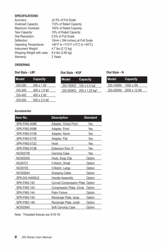
PEAK HOlDThe DG Series force gauge has a maximum hold feature. This allows the peak force to be held after the load is removed.
AcTivATE PEAK HOlD To activate this feature, rotate the knob to “MAX ON”position.
RESET PEAK HOlDTo reset the reading, simply rotate the switch to “MAXOFF”andthenreturnbackto“MAXON” position. To deactivate this feature, rotate the knob tothe“MAXOFF”position.
TEST STAND MOUNTiNGThe DG Series force gauge has four #10-32 female threads for mounting to CHATILLON test stands. Ensure the #10-32 screws are not too long, other-wise it may bind and damage the force gauge.
The screw thread length going into the back of the gauge should not exceed 3/8 inch.
MAiNTENANcEGauge accuracy should be checked periodically to ensure the gauge is within its calibration limits. Thecalibrationcanbeverifiedbyapplyingknownweights (adjusted for local gravity) to the extension hook. If adjustment is required, the gauge should be returned to AMETEK for calibration.
Test Stand Adapters
item No. Fits Tester
SPK-MT-0005 MT150, MT500 SPK-DG-TT TT Testers
6 DG Series User Manual
SPEciFicATiONSAccuracy: +0.5% of Full ScaleOverload Capacity: 110% of Rated CapacityMaximum Overload: 150% of Rated Capacity Tare Capacity: 10% of Rated CapacityDial Resolution: 0.5% of Full ScaleDeflection: 10mm(.394inches)atFullScaleOperatingTemperature: +40°Fto+110°F(+5°Cto+45°C)InstrumentWeight: 4.7lbs(2.12kg)ShippingWeightwithcase: 8.4lbs(3.80kg)Warranty: 2 Years
ORDERiNG
Dial Style - lBF
Model capacity
DG-200 200 x 1 lbf DG-300 300 x 1.5 lbfDG-400 400x2lbf DG-500 500 x 2.5 lbf
Dial Style - KGF
Model capacity
DG-100KG 100 x 0.5 kgf DG-250KG 250 x 1.25 kgf
Dial Style - N
Model capacity
DG-1000N 1000 x 5N DG-2500N 2500 x 12.5N
Accessories
item No. Description Standard
SPK-FMG-008B Adapter, Chisel Point Yes SPK-FMG-009B Adapter, Point Yes SPK-FMG-010B Adapter, Notch Yes SPK-FMG-011B Adapter, Flat Yes SPK-FMG-012C Hook YesSPK-FMG-013B ExtensionRod,6” Yes NC002728 Carrying Case Yes NC002500 Hook, Snap Clip Option NC00721 V-Notch, Small Option NC00725 V-Notch, Large OptionNC002844 GraspingCable Option SPK-DG-HANDLE Handle Assembly OptionSPK-FMG-142 CurvedCompressionPlate OptionSPK-FMG-143 CompressionPlate,Circle OptionSPK-FMG-144 PalmFixture OptionSPK-FMG-145 RectanglePlate,large OptionSPK-FMG-146 RectanglePlate,small OptionNC002845 SoftCarryingCase Option
Note:Threadedfixturesare5/16-18.
DG Series User Manual 7
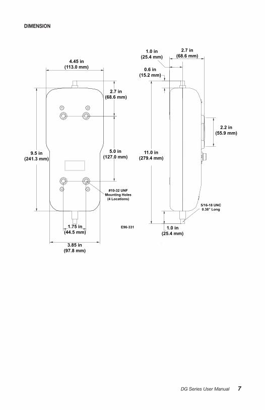
DiMENSiON
1.75 in(44.5 mm)
#10-32 UNFMounting Holes
(4 Locations)
3.85 in(97.8 mm)
9.5 in(241.3 mm)
4.45 in(113.0 mm)
2.7 in(68.6 mm)
5.0 in(127.0 mm)
11.0 in(279.4 mm)
5/16-18 UNC0.38” Long
1.0 in(25.4 mm)
E96-331
1.0 in(25.4 mm)
0.6 in(15.2 mm)
2.7 in(68.6 mm)
2.2 in(55.9 mm)
8 DG Series User Manual
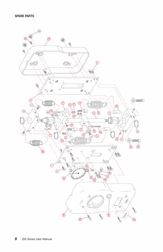
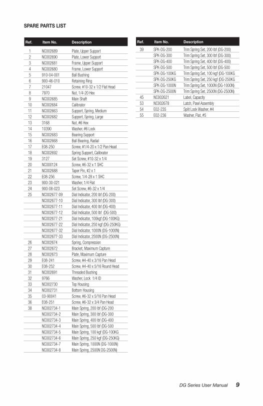
SPARE PARTS
DG Series User Manual 9
1 NC002689 Plate, Upper Support 2 NC002690 Plate, Lower Support 3 NC002681 Frame, Upper Support 4 NC002680 Frame, Lower Support 5 910-04-001 Ball Bushing 6 900-46-010 Retaining Ring 7 21047 Screw, #10-32 x 1/2 Flat Head 8 7970 Nut, 1/4-20 Hex 9 NC002685 Main Shaft 10 NC002684 Calibrator 11 NC002663 Support, Spring, Medium 12 NC002682 Support, Spring, Large 13 3168 Nut, #6 Hex 14 10390 Washer, #6 Lock 15 NC002683 Bearing Support 16 NC002668 Ball Bearing, Radial 17 E08-250 Screw, #1/4-20 x 1/2 Pan Head 18 NC002692 Spring Support, Calibrator 19 3127 Set Screw, #10-32 x 1/4 20 NC000124 Screw, #6-32 x 1 SHC 21 NC002688 Taper Pin, #2 x 1 22 E08-256 Screw, 1/4-28 x 1 SHC 23 900-30-021 Washer, 1/4 Flat 24 900-08-023 Set Screw, #6-32 x 1/4 25 NC002677-09 Dial Indicator, 200 lbf (DG-200) NC002677-10 Dial Indicator, 300 lbf (DG-300) NC002677-11 Dial Indicator, 400 lbf (DG-400) NC002677-12 Dial Indicator, 500 lbf (DG-500) NC002677-21 Dial Indicator, 100kgf (DG-100KG) NC002677-22 Dial Indicator, 250 kgf (DG-250KG) NC002677-32 Dial Indicator, 1000N (DG-1000N) NC002677-33 Dial Indicator, 2500N (DG-2500N) 26 NC002674 Spring, Compression 27 NC002672 Bracket, Maximum Capture 28 NC002673 Plate, Maximum Capture 29 E08-241 Screw, #4-40 x 3/16 Pan Head 30 E08-252 Screw, #4-40 x 5/16 Round Head 31 NC002691 Threaded Bushing 32 9766 Washer, Lock 1/4 ID 33 NC002730 Top Housing 34 NC002731 Bottom Housing 35 03-90041 Screw, #6-32 x 5/16 Pan Head 36 E08-251 Screw, #6-32 x 3/4 Pan Head 38 NC002734-1 Main Spring, 200 lbf (DG-200 NC002734-2 Main Spring, 300 lbf (DG-300 NC002734-3 Main Spring, 400 lbf (DG-400 NC002734-4 Main Spring, 500 lbf (DG-500 NC002734-5 Main Spring, 100 kgf (DG-100KG NC002734-6 Main Spring, 250 kgf (DG-250KG) NC002734-7 Main Spring, 1000N (DG-1000N) NC002734-8 Main Spring, 2500N DG-2500N)
39 SPK-DG-200 Trim Spring Set, 200 lbf (DG-200) SPK-DG-300 Trim Spring Set, 300 lbf (DG-300) SPK-DG-400 Trim Spring Set, 400 lbf (DG-400) SPK-DG-500 Trim Spring Set, 500 lbf (DG-500 SPK-DG-100KG Trim Spring Set, 100 kgf (DG-100KG SPK-DG-250KG Trim Spring Set, 250 kgf (DG-250KG SPK-DG-1000N Trim Spring Set, 1000N (DG-1000N) SPK-DG-2500N Trim Spring Set, 2500N (DG-2500N) 45 NC002621 Label, Capacity 53 NC002678 Latch, Pawl Assembly 54 E02-235 Split Lock Washer, #4 55 E02-236 Washer, Flat, #5
Ref. item No. Description Ref. item No. Description
SPARE PARTS liST

10 DG Series User Manual
www.chatillon.com
UKlloyd instruments ltdTel +44 (0)1243 833 [email protected]
FranceAMETEK S.A.S.Tel +33 (0)1 30 68 89 [email protected]
GermanyAMETEK GmbHTel +49 (0)2159 9136 [email protected]
DenmarkAMETEK DenmarkTel +45 4816 [email protected]
USAAMETEK Measurement & Calibration TechnologiesTel +1 (727) 536 [email protected]
indiaAMETEK Instruments India Pvt Ltd.Tel +91 22 2836 [email protected]
Singapore AMETEK Singapore Pte LtdTel +65 6484 [email protected]
chinaAMETEK Inc. - ShanghaiTel +86 21 5868 5111
AMETEK Inc. - BeijingTel +86 10 8526 2111
AMETEK Inc. - GuangzhouTel +86 20 8363 [email protected]
Information in this document is subject to change without notice. ©2012 by AMETEK, Inc., www.ametek.com. All rights reserved.


![JEDEC MANUAL1].pdf · JC-11.13 Subcommittee: Gauges and Tools for Semiconductor Packages and Related Parts (Inactive) Specifies mechanical measuring methods, mechanical gauges, fixtures,](https://img.pdfslide.us/doc/110x75/600b8b9535a6c72df26fcc96/jedec-manual-1pdf-jc-1113-subcommittee-gauges-and-tools-for-semiconductor.jpg)