Embed Size (px)
Citation preview

DG-SC3630 / DG-SC3610W
Wired/Wireless IP Surveillance
Pan/Tilt Camera
User Manual
V1.1
2011-08-16
As our products undergo continuous development the specifications are subject to change without prior notice

DG-SC3630 / DG-SC3610W User Manual
2
COPYRIGHT
Copyright © 2011 by this company. All rights reserved. No part of this
publication may be reproduced, transmitted, transcribed, stored in a retrieval
system, or translated into any language or computer language, in any form or
by any means, electronic, mechanical, magnetic, optical, chemical, manual or
otherwise, without the prior written permission of this company.
This company makes no representations or warranties, either expressed or
implied, with respect to the contents hereof and specifically disclaims any
warranties, merchantability or fitness for any particular purpose. Any software
described in this manual is sold or licensed "as is". Should the programs prove
defective following their purchase, the buyer (and not this company, its
distributor, or its dealer) assumes the entire cost of all necessary servicing,
repair, and any incidental or consequential damages resulting from any defect
in the software. Further, this company reserves the right to revise this
publication and to make changes from time to time in the contents thereof
without obligation to notify any person of such revision or changes.
Trademarks: DIGISOL™ is a trademark of Smartlink Network Systems Ltd. All other
trademarks are the property of the respective manufacturers.
Safety This equipment is designed with the utmost care for the safety of those who
install and use it. However, special attention must be paid to the dangers of
electric shock and static electricity when working with electrical equipment. All
guidelines of this and of the computer manufacturer must therefore be allowed
at all times to ensure the safe use of the equipment.

DG-SC3630 / DG-SC3610W User Manual
3
INDEX INDEX ...........................................................................................................................3
1 Getting familiar with your Internet IP Camera ...........................................................6
1.1 Basic Introduction........................................................................................6
1.2 Product Features .........................................................................................7
1.3 Preparation Before Installation ..................................................................8
1.4 Technical Specifications .............................................................................9
1.5 Hardware Description ...............................................................................10
1.6 Camera Installation ...................................................................................16
1.7 Locate the IP Address of this IP Camera...............................................20
1.8 Using Camera Admin Software to Locate Camera ..............................24
1.9 Log On to Web Management Interface..................................................32
2 Using Web Management Interface............................................................................37
2.1 Camera Settings ...........................................................................................37
2.2 Video...............................................................................................................41
2.2.1 MJPEG....................................................................................................42
2.2.2 MPEG4 ...................................................................................................43
2.2.3 H.264.......................................................................................................44
2.2.4 OSD.........................................................................................................46
2.2.5 Night Vision.............................................................................................47
2.3 Pan and Tilt....................................................................................................48
2.3.1 Preset Points ...........................................................................................48
2.3.2 Guard Tour ..............................................................................................50
2.4 Network Settings...........................................................................................53
2.4.1 LAN .........................................................................................................55
2.4.2 WLAN ......................................................................................................57
2.4.3 Dynamic DNS..........................................................................................63
2.4.4 UPnP.......................................................................................................64
2.4.5 LoginFree................................................................................................66
2.4.6 RTSP .......................................................................................................67
2.5 Motion Detection ...........................................................................................68
2.5.1 Motion Detection ....................................................................................69

DG-SC3630 / DG-SC3610W User Manual
4
2.5.2 Motion Region.........................................................................................71
2.5.3 Email .......................................................................................................73
2.5.4 FTP Configuration..................................................................................75
2.5.5 SD Card Configuration ...........................................................................76
2.6 System Info....................................................................................................77
2.6.1 Camera Information................................................................................78
2.6.2 Date / Time Setting..................................................................................79
2.6.3 Utilities....................................................................................................80
2.6.4 Status .......................................................................................................82
2.7 Account...........................................................................................................83
2.8 SDHC..............................................................................................................86
2.8.1 Status .......................................................................................................87
2.8.2 Space Alarm ............................................................................................87
2.8.3 File Management ....................................................................................89
3 Using SKYROS Surveillance Manager Software.....................................................90
3.1 Installing SKYROS Surveillance Manager Software...............................90
3.2 Using SKYROS Surveillance Manager software .....................................95
3.3 Configuring the SKYROS Surveillance Manager software ....................98
3.3.1 Configuring cameras ..............................................................................98
3.3.1.1 ‘Camera’ tab.........................................................................................99
3.3.1.2 Schedule Recording ...........................................................................101
3.3.1.3 Audio..................................................................................................104
3.3.1.4 Motion Record ...................................................................................105
3.3.2 General Settings....................................................................................107
3.3.2.1 ‘General’ tab.......................................................................................107
3.3.2.2 ‘E-Mail Setting’ tab............................................................................109
3.3.2.3 Security .............................................................................................. 111
3.3.2.4 About..................................................................................................113
3.4 Change Display Layout .............................................................................114
3.5 Full-screen mode ........................................................................................117
3.6 Scan..............................................................................................................118
3.7 Zoom-in / Zoom-out....................................................................................119
3.8 PTZ ...............................................................................................................120
DG-SC3630 / DG-SC3610W User Manual
5
3.9 Snapshot ......................................................................................................121
3.10 Recording ..................................................................................................122
3.11 Video Playback .........................................................................................123
4. Appendix ................................................................................................................124
4.1 Specification ................................................................................................124
4.2 Troubleshooting ..........................................................................................125
4.3 Obtain a free Dyndns account ..................................................................129
4.4 IP Camera behind a router/firewall – Sample Configuration ...............135
4.4.1 Setup Dyndns Dynamic IP address Mapping........................................135
4.4.2 Open Ports Required by IP CAM..........................................................136
4.4.3 DMZ Settings ........................................................................................137
4.5 Using Cellphone as Image Viewer...........................................................139
4.5.1 iPhone ...................................................................................................139
4.6 Windows Vista / Windows 7 UAC Configuration ...................................143
Glossary .....................................................................................................................146
DG-SC3630 / DG-SC3610W User Manual
6
1 Getting familiar with your Internet IP Camera
1.1 Basic Introduction
Thank you for purchasing this Internet IP camera. This IP camera is an ideal product
for all kinds of video-surveillance purposes, like home/office safety, kid/pet monitoring,
and remote video acquire etc. Unlike conventional close-circuit video camera; you’re
not limited to the length of the cable. Once this IP camera is connected to Internet, you
can receive video from anywhere in the world where Internet access is available.
If you have problem installing a new cable from the place the camera is installed to
your monitoring computer, don’t worry. This IP camera also supports wireless network,
that is, you can link to this camera wirelessly. You only have to provide this IP camera
with 12V power by the power adapter that comes with the product package, and you
don’t have to set a new network cable between the IP camera and monitoring
computer.
Unlike conventional analog wireless camera, in which video will be intercepted by
anyone who got a compatible video receiver, this IP camera supports data encryption
(WEP & WPA), which will provide ultimate data security level. All video transmitted
over the air is encrypted; therefore no one will be able to get the video captured by the
IP camera, except yourself.
Some people may be concerned that there will be some places which will not be
covered by the camera, but this problem is completely solved by this IP camera. With
built-in pan-tilt function, you can point the camera to the position where you wish to
look at with user interface. You can even define a preset path, and the camera will
cruise along the path you defined.
If the environment is too dark, it’s also not a problem. This camera equips IR-LEDs and
will illuminate automatically when the environment is too dark, and the image captured
by this camera will still be clear.

DG-SC3630 / DG-SC3610W User Manual
7
1.2 Product Features
No pre-loaded software required - all you need is a browser like Internet
Explorer 6 (and above, with plug-in installed).
With supplied SKYROS manager software, you can connect up to 16 video
cameras and view images captured by every camera at the same time.
Supports 3 video resolutions: MJPEG and H.264 SXGA (1280 x 1024), VGA
(640 x 480), and QVGA (320 x 240); MPEG4 XGA (1024 x 768), VGA (640 x
480), and QVGA (320 x 240).
Anti-flicker function (eliminates flash caused by fluorescent lights, 50 / 60Hz
selectable).
Video control functions, like brightness and zoom-in / zoom-out.
Audio function, suitable for applications like video conference or
environment monitor.
8 Automatically-controlled IR LEDs.
Wired and wireless network (802.11b / 802.11g / 802.11n) supports up to
100Mbps for wired network.
Wired model (DG-SC3630) supports PoE feature.
Wireless data encryption (WEP / WPA)
Supports DHCP and PPPoE protocol, you can also assign a fixed IP
address to the camera.
Supports Dynamic DNS (used to allocate the IP camera’s Internet address,
when the ISP you’re using does not assign a fixed Internet address for that
purpose).
Using UPnP, Windows XP (and above) will discover this IP camera in
network neighbor automatically.
Send captured picture and video by Email or FTP when motion is detected.
Adjustable motion detection sensitivity.
Built-in clock, date and time information will be recorded with every captured
picture / video clip (also supports auto time synchronization via network time
protocol).
Upgradeable firmware - enjoy new functions without buying a new camera.

DG-SC3630 / DG-SC3610W User Manual
8
Supports up to 16 users, and you can set a unique password for each user.
Usage and event logging.
1.3 Preparation Before Installation
Package Contents
IP Camera
Two Antennas (Only for DG-SC3610W model)
Power Adapter (12 V DC, 1A)
Ethernet Cable
Installation Software CD-ROM
Accessory Kit
System Requirements
Computer with Windows® 7, Vista or XP
PC with dual core or above; at least 2GB RAM
Internet Explorer 6.0 or above
Existing 10/100 Ethernet-based network or wireless 802.11b/g/n network(for
wireless model only)

DG-SC3630 / DG-SC3610W User Manual
9
1.4 Technical Specifications
Environment Requirements: The whole device can survive in a wide range of operating temperature and can work normally and stably in tough environment.
Operating temperature: 0˚C—40˚C Relative humidity: 10%—90% (non-condensing)
Power:
12V DC, 1A power adaptor 802.3af PoE (DG-SC3630 only)
Physical Characteristics: Dimension (L x W x H): 125mmx112mmx113mm (DG-SC3630)
125mmx119mmx113mm (DG-SC3610W)
Weight: 290gms (DG-SC3630)
310gms (DG-SC3610W)

DG-SC3630 / DG-SC3610W User Manual
10
1.5 Hardware Description
Power LED: Indicates power status
Audio LED: Indicates Audio status
LAN LED: Indicates LAN activity
ACT LED: Indicates Data activity
WLAN LED: Indicates Wireless LAN activity
Front View of wired (PoE) and wireless models
Focus Ring
IR LEDs
Microphone
Power LED Audio LED LAN LED WLAN LED Wireless model:
Wired model: Power LED Audio LED ACT LED LAN LED
Light Sensor

DG-SC3630 / DG-SC3610W User Manual
11
Focus Ring: Adjusts focus by rotating it to get a clear image.
IR LEDs: 8 LED’s light up when the environment is too dark. An additional 9th
LED is for future provision.
Light Sensor: Senses variation in the intensity of light.
Microphone: Collects audio
Antenna Base
Antenna Base: Connects to supplied antenna
Power Connector: Connects to 12V DC power adapter
SD Card Slot: Accepts SD / SD-HC memory card for image / video storage
Back View of wireless model
Antenna Base Power Connector SD Card Slot WPS Button Audio Connector
Ethernet
Connector
DG-SC3630 / DG-SC3610W User Manual
12
WPS Button: Click the button on IP Cam and click it on the AP you want to
connect for wireless
Audio Connector: Connects to external speaker for audio output
Ethernet Connector: Connect to your local area network
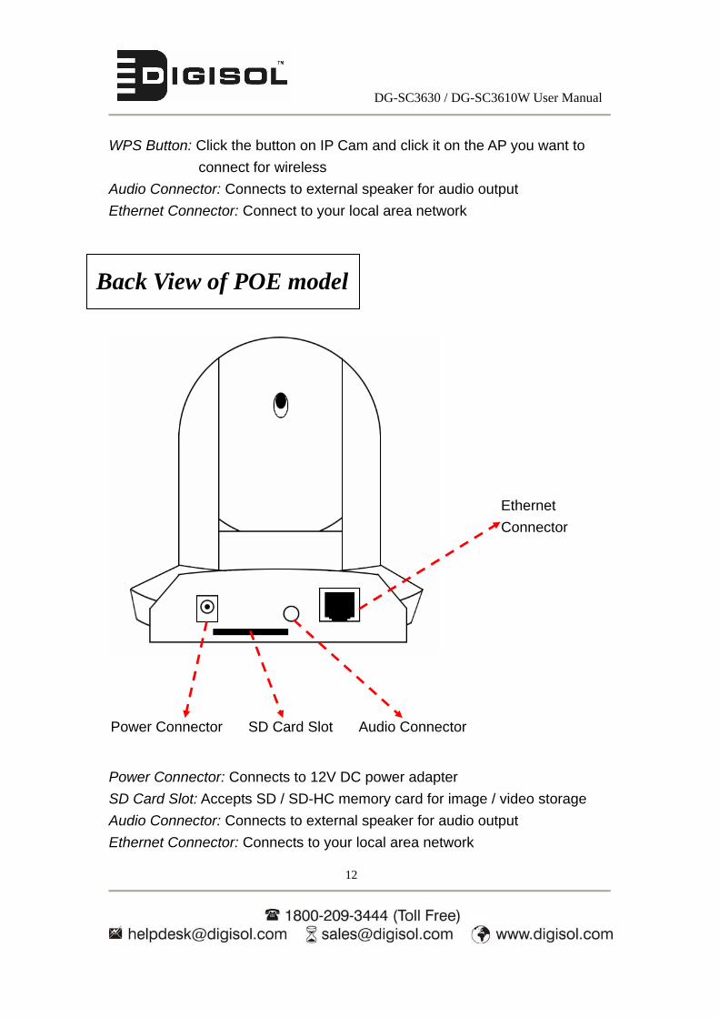
Power Connector: Connects to 12V DC power adapter
SD Card Slot: Accepts SD / SD-HC memory card for image / video storage
Audio Connector: Connects to external speaker for audio output
Ethernet Connector: Connects to your local area network
Back View of POE model
Power Connector SD Card Slot Audio Connector
Ethernet
Connector

DG-SC3630 / DG-SC3610W User Manual
13
Reset Button: Keep the button pressed with pen nib until all the LED’s on the
camera go off, to reset the camera settings to factory default
value.
Side View of Wired and Wireless model
Reset Button

DG-SC3630 / DG-SC3610W User Manual
14
Tripod Connector: Connects to tripod to secure the camera when the camera is
not placed on a horizontal surface.
Bottom View of Wired and Wireless model
Tripod Connector
DG-SC3630 / DG-SC3610W User Manual
15
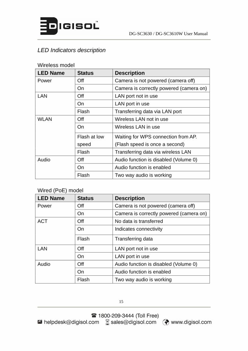
LED Indicators description
Wireless model
LED Name Status Description Off Camera is not powered (camera off) Power
On Camera is correctly powered (camera on)
Off LAN port not in use
On LAN port in use
LAN
Flash Transferring data via LAN port
Off Wireless LAN not in use
On Wireless LAN in use
Flash at low
speed
Waiting for WPS connection from AP.
(Flash speed is once a second)
WLAN
Flash Transferring data via wireless LAN
Off Audio function is disabled (Volume 0)
On Audio function is enabled
Audio
Flash Two way audio is working
Wired (PoE) model
LED Name Status Description Off Camera is not powered (camera off) Power
On Camera is correctly powered (camera on)
Off No data is transferred
On Indicates connectivity
ACT
Flash Transferring data
Off LAN port not in use LAN
On LAN port in use
Off Audio function is disabled (Volume 0)
On Audio function is enabled
Audio
Flash Two way audio is working

DG-SC3630 / DG-SC3610W User Manual
16
1.6 Camera Installation
Please follow the below mentioned instructions to set up your IP camera.
1. Unpack the product package and check if anything’s missing.
2. Connect the Ethernet cable to your local area network, and connect the
other end to the LAN jack of this IP camera.
NOTE: You can skip this step if you plan to use wireless LAN only.

DG-SC3630 / DG-SC3610W User Manual
17
3. Plug the power adapter to wall socket, and connect the power connector to
the power jack located at the bottom of the IP camera.

DG-SC3630 / DG-SC3610W User Manual
18
4. For the wireless version, connect two antennas to the antenna bases, which
is located at the back of this IP camera.
DG-SC3630 / DG-SC3610W User Manual
19
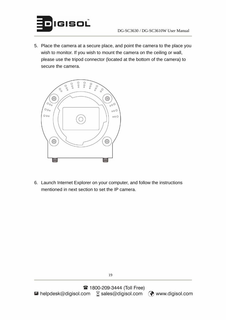
5. Place the camera at a secure place, and point the camera to the place you
wish to monitor. If you wish to mount the camera on the ceiling or wall,
please use the tripod connector (located at the bottom of the camera) to
secure the camera.
6. Launch Internet Explorer on your computer, and follow the instructions
mentioned in next section to set the IP camera.
DG-SC3630 / DG-SC3610W User Manual
20
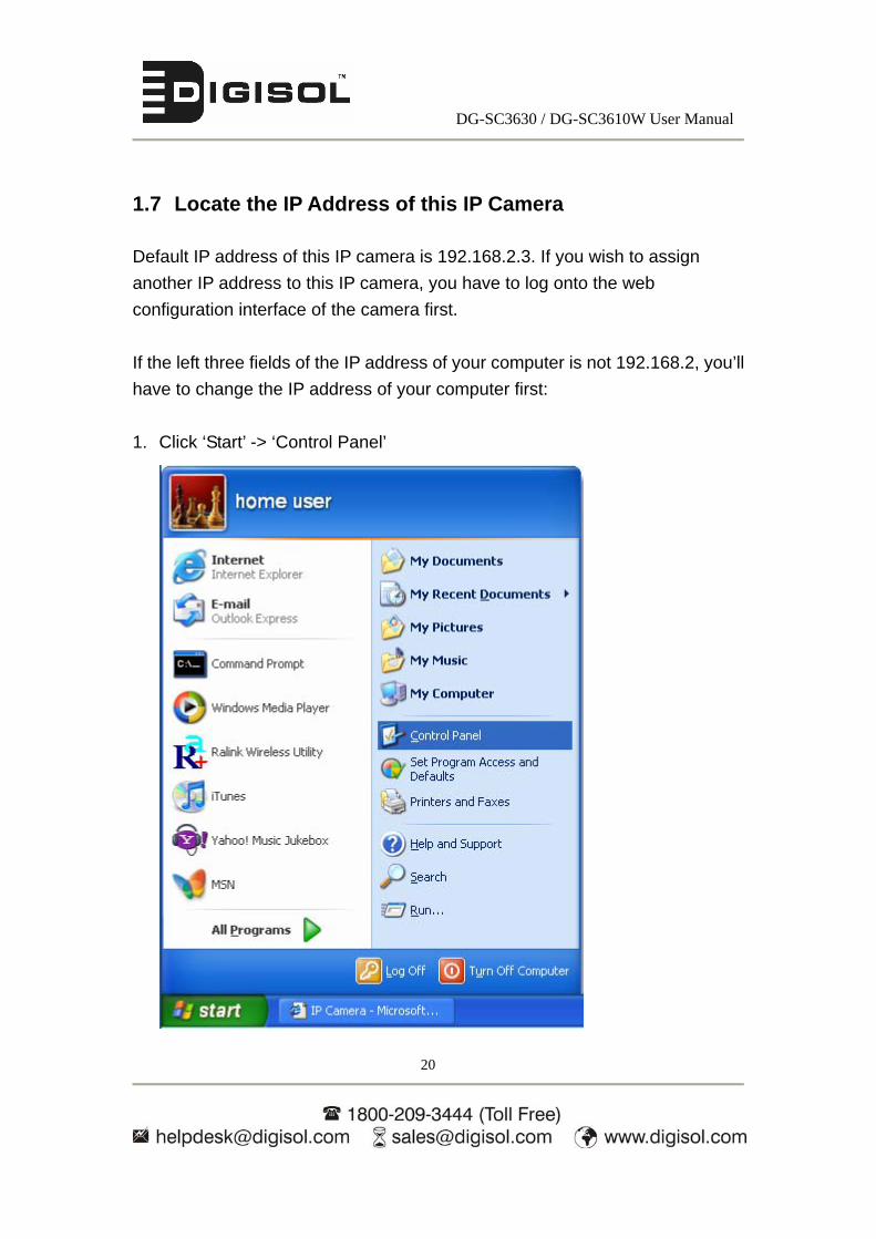
1.7 Locate the IP Address of this IP Camera
Default IP address of this IP camera is 192.168.2.3. If you wish to assign
another IP address to this IP camera, you have to log onto the web
configuration interface of the camera first.
If the left three fields of the IP address of your computer is not 192.168.2, you’ll
have to change the IP address of your computer first:
1. Click ‘Start’ -> ‘Control Panel’

DG-SC3630 / DG-SC3610W User Manual
21
2. Double-click ‘Network Connections’ icon.
3. Right-click ‘Local Area Connection’, and click ‘Properties’.
DG-SC3630 / DG-SC3610W User Manual
22
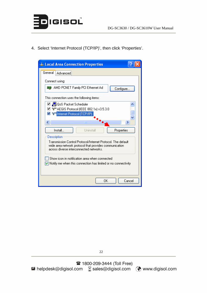
4. Select ‘Internet Protocol (TCP/IP)’, then click ‘Properties’.
DG-SC3630 / DG-SC3610W User Manual
23
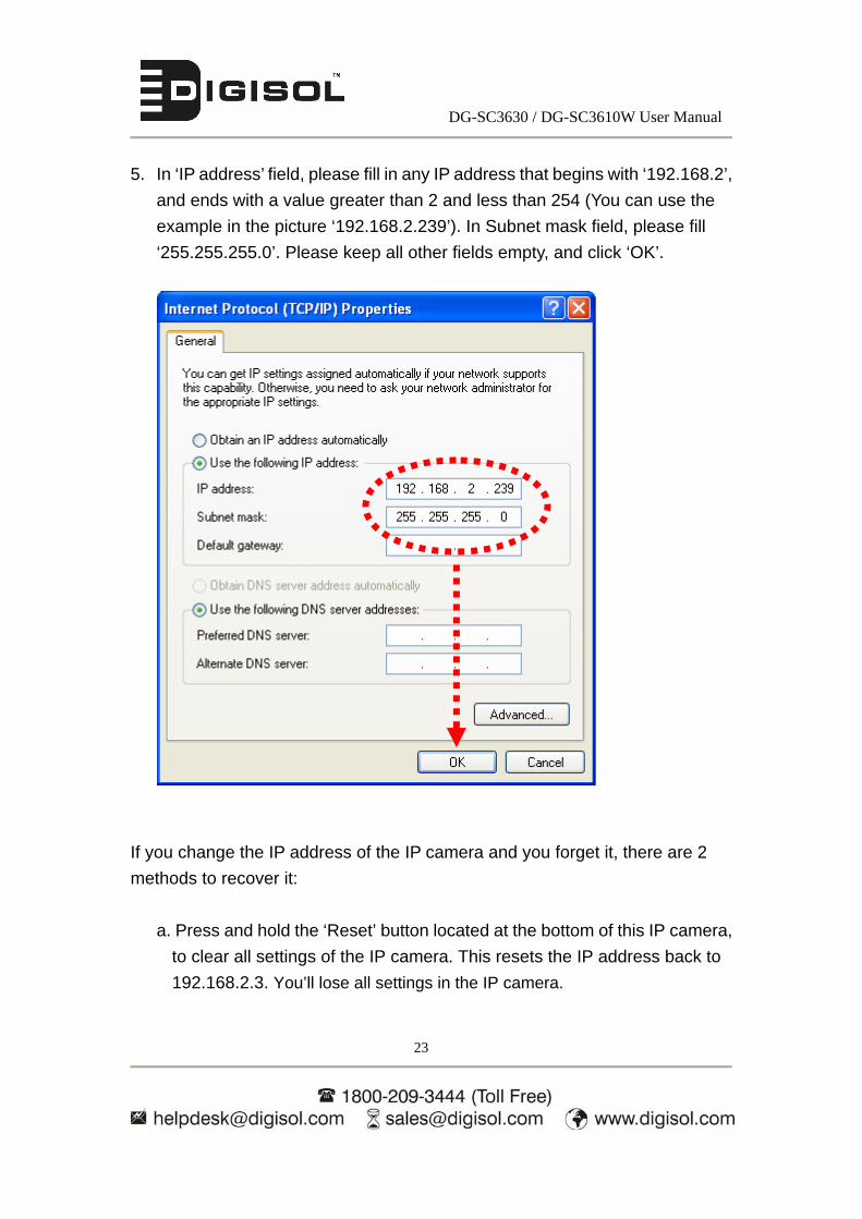
5. In ‘IP address’ field, please fill in any IP address that begins with ‘192.168.2’,
and ends with a value greater than 2 and less than 254 (You can use the
example in the picture ‘192.168.2.239’). In Subnet mask field, please fill
‘255.255.255.0’. Please keep all other fields empty, and click ‘OK’.
If you change the IP address of the IP camera and you forget it, there are 2
methods to recover it:
a. Press and hold the ‘Reset’ button located at the bottom of this IP camera,
to clear all settings of the IP camera. This resets the IP address back to
192.168.2.3. You’ll lose all settings in the IP camera.

DG-SC3630 / DG-SC3610W User Manual
24
b. Ask the network administrator to check the DHCP release table. If the
camera was set to obtain the IP address by DHCP, a new record will be
added to DHCP release table on DHCP server when the IP camera is
connected to the local area network.
1.8 Using Camera Admin Software to Locate Camera
If you can’t connect to the camera by the instructions given in the last section,
you can use camera admin software to search the camera which is connected
to your local area network. The admin software is also capable to locate
multiple cameras on your local area network.
Please insert the Installation Software CD-ROM supplied in the product
package and the CD will automatically run the installation, if not please follow
the instructions mentioned below:
Click on My Computer
Right click and open CD ROM drive with Digisol ‘D’ icon having the name
as ‘DG-SC3630’ or ‘DG-SC3610W’ depending on the camera type as
shown below.

DG-SC3630 / DG-SC3610W User Manual
25
Next click on admin folder as shown below.
Double click setup icon ‘Skyros_Admin_Setup_v3.0.26’ and ‘Skyros
Installation Wizard’ will open.
DG-SC3630 / DG-SC3610W User Manual
26
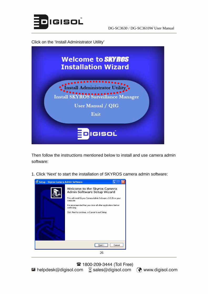
Click on the ‘Install Administrator Utility’
Then follow the instructions mentioned below to install and use camera admin
software:
1. Click ‘Next’ to start the installation of SKYROS camera admin software:

DG-SC3630 / DG-SC3610W User Manual
27
2. You can change the installation folder of camera setup software here, click
‘Browse’ to select an existing folder or you can just click ‘Next’ to use default
installation folder:
3. If you wish to create desktop icon and / or quick launch icon for camera
admin software, please check corresponding box, and click ‘Next’ to
continue.

DG-SC3630 / DG-SC3610W User Manual
28
4. You’ll see a brief of all options you selected, click ‘Install’ to install camera
admin software now or click ‘back’ to go back to previous steps to change
settings.
5. When you see this message, the installation of camera admin software is
complete. If you wish to launch camera admin software now, keep ‘Launch
IP Cam Admin Utility’ box checked, and click ‘Finish’ to close installation
utility.

DG-SC3630 / DG-SC3610W User Manual
29
After the camera admin software is launched, all cameras found on your local
area network will be displayed.
If you wish to connect to a particular camera, click on it and all camera-related
information will be displayed here. Next, double-click on that camera and its
webpage will open.
The camera admin software also provides several functions:
Search camera: Click this button to search all cameras on local area
network again.
Browse camera via web: Select a camera listed above first, and then click this button to connect to the camera by
web browser.
Configure camera: Click this button to configure camera’s network and
security setting. You’ll be prompted to input
camera’s password:

DG-SC3630 / DG-SC3610W User Manual
30
Input the password (default: 1234) and click OK to configure the camera’s
network and security settings.
In this menu, you can configure camera’s network settings. Select ‘DHCP’ to
set the camera to obtain an IP address from DHCP server on local area network
automatically, and select ‘Manual IP’ to input the IP address information
manually. Click ‘OK’ to save settings.

DG-SC3630 / DG-SC3610W User Manual
31
In ‘Security’ page, you can change the camera’s name and password (user
name is always ‘admin’ and cannot be changed). You have to input the same
password in both ‘New Password’ and ‘Confirm Password’ field, or you’ll be
prompted to input new password again. Click ‘OK’ to save settings or click
‘Cancel’ to discard changes.
DG-SC3630 / DG-SC3610W User Manual
32
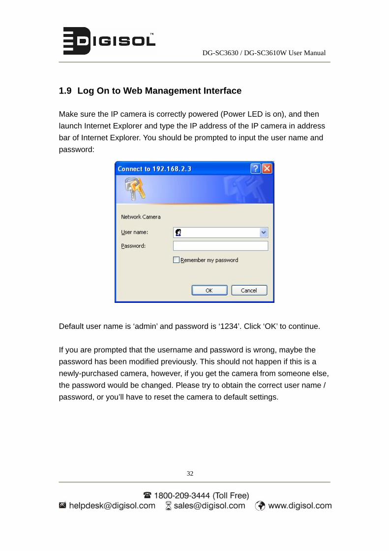
1.9 Log On to Web Management Interface
Make sure the IP camera is correctly powered (Power LED is on), and then
launch Internet Explorer and type the IP address of the IP camera in address
bar of Internet Explorer. You should be prompted to input the user name and
password:
Default user name is ‘admin’ and password is ‘1234’. Click ‘OK’ to continue.
If you are prompted that the username and password is wrong, maybe the
password has been modified previously. This should not happen if this is a
newly-purchased camera, however, if you get the camera from someone else,
the password would be changed. Please try to obtain the correct user name /
password, or you’ll have to reset the camera to default settings.
DG-SC3630 / DG-SC3610W User Manual
33
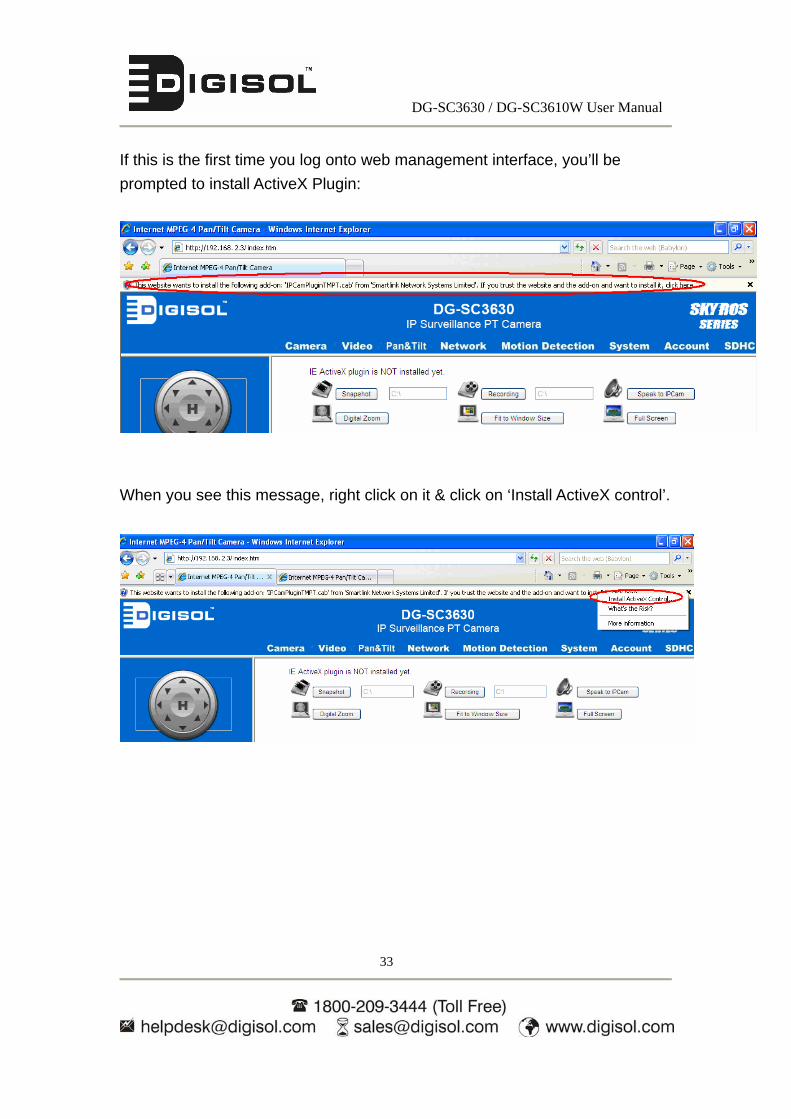
If this is the first time you log onto web management interface, you’ll be
prompted to install ActiveX Plugin:
When you see this message, right click on it & click on ‘Install ActiveX control’.

DG-SC3630 / DG-SC3610W User Manual
34
Once you click on ‘Install ActiveX Control option, the following window will be
displayed on the screen. Click on ‘Install’
After the installation process is completed, go back to web browser, and you
should be able to see the image captured by camera (You may need to press
F5 or CTRL-R to reload web page).

DG-SC3630 / DG-SC3610W User Manual
35
Note: If you see one of these messages (or both):
Your computer may not have the display capability that this IP camera requires,
or you don’t have Microsoft DirectX® installed. Please download Microsoft
DirectX® from Microsoft’s website (http://www.microsoft.com), and try again.
In some cases, your computer is able to display the image from IP camera
correctly, but you’ll still see these messages. If this happens, just ignore them.
OR

DG-SC3630 / DG-SC3610W User Manual
36
Special notes:
This IP camera has IR coating lens hence if you enable the IR feature on the
camera in normal light conditions (bright), the image will be displayed as below:
If you disable the IR feature on the camera in normal light conditions (bright),
the image will be displayed as below:

DG-SC3630 / DG-SC3610W User Manual
37
2 Using Web Management Interface
2.1 Camera Settings
The first menu after you logged onto web management interface is ‘Camera’,
and this is the only menu on which you can see the real-time image from
camera.
You can always go back to this menu by clicking ‘Camera’ on the top of web
management interface.

DG-SC3630 / DG-SC3610W User Manual
38
The description of every setting in this menu will be given below:
Item Description
Pan & Tilt Speed Specifies the moving speed when you use pan /
tilt function to point the camera to a new direction.
Available options are 1 (fastest) to 5 (slowest).
Select 1 to move the camera by a faster speed,
but you will not be able to control the movement
precisely. If you want to move the camera in a
more accurate manner, select a slower speed.
Video Type Specifies video encoding type. Available options
are ‘MPEG4’, ‘MJPEG’, and ‘H.264’. Different
encoding types require different bandwidth, and
provide different video quality.
Frequency If the image on the IP camera has fluorescent
light(s), the image may look flashing. In this case,
you can adjust this setting to the frequency of
electrical power; this can improve the image
quality effectively. If you don’t know which one

DG-SC3630 / DG-SC3610W User Manual
39
you should use, just try any of them and select
one with fewer flickers.
Flip Mode If you’re not putting this camera on a horizontal
surface but mounting it on the ceiling or wall, you
can use this function to rotate the displaying
image.
Brightness /
Saturation /
Sharpness
Select brightness, saturation, and sharpness from
dropdown menu, and click ‘- ' or ‘+ ‘button to
increase or decrease brightness / saturation /
sharpness setting value. In certain environment,
adjusting brightness, saturation, and / or
sharpness will help to improve video quality.
Volume Adjust the volume of audio output. Press ‘+’ or
‘-‘ button to increase or decrease volume.
NOTE: When you change any setting(s) listed above, please click ‘Apply’ button
so the change(s) will take effect. For following functions, changes will take effect
right away.
Pan / Tilt Control
Moves camera to a new direction. Press one of 8
directional buttons to move the camera, and press
‘H’ to move the camera back to ‘home’ (original)
position.
Preset Points
You can set up to 9 preset points of camera position;
press the number to move the camera to preset point
instantly. See section 2.3.1 for detail instructions of
how to set preset points.
Press ‘C’ and the camera will cruise between all
preset points automatically.
Snapshot
Click ‘Snapshot’ button to save the displayed image
as an image file, a message box will appear after you
click ‘Snapshot’ button, showing the filename and
location of saved image file (default filename is
DG-SC3630 / DG-SC3610W User Manual
40
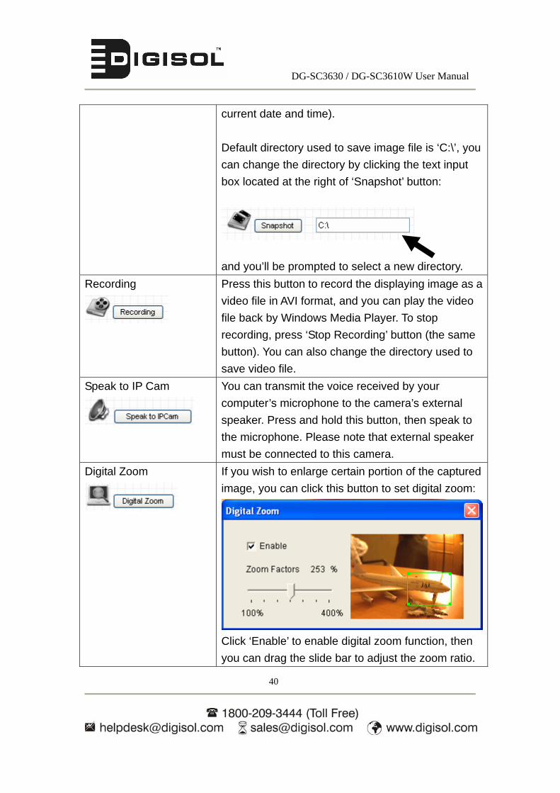
current date and time).
Default directory used to save image file is ‘C:\’, you
can change the directory by clicking the text input
box located at the right of ‘Snapshot’ button:
and you’ll be prompted to select a new directory.
Recording
Press this button to record the displaying image as a
video file in AVI format, and you can play the video
file back by Windows Media Player. To stop
recording, press ‘Stop Recording’ button (the same
button). You can also change the directory used to
save video file.
Speak to IP Cam
You can transmit the voice received by your
computer’s microphone to the camera’s external
speaker. Press and hold this button, then speak to
the microphone. Please note that external speaker
must be connected to this camera.
Digital Zoom
If you wish to enlarge certain portion of the captured
image, you can click this button to set digital zoom:
Click ‘Enable’ to enable digital zoom function, then
you can drag the slide bar to adjust the zoom ratio.

DG-SC3630 / DG-SC3610W User Manual
41
You can also use your mouse to drag the zoom area
(the green square) to reposition the zoom area.
Fit to Window Size
Click this button and the image size will be adjusted
to fit the size of the browser window.
Full Screen
Click this button to display the image in full-screen
mode (uses all available space to display the image
captured by this camera).
2.2 Video
You can change video-related settings of this IP camera in ‘Video’ menu. You can access this menu by clicking ‘Video’ on the top of web
management interface.
DG-SC3630 / DG-SC3610W User Manual
42
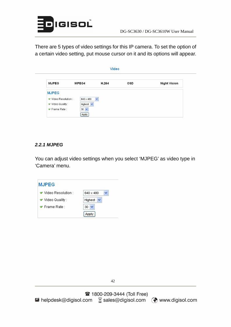
There are 5 types of video settings for this IP camera. To set the option of a certain video setting, put mouse cursor on it and its options will appear.
2.2.1 MJPEG
You can adjust video settings when you select ‘MJPEG’ as video type in ‘Camera’ menu.

DG-SC3630 / DG-SC3610W User Manual
43
The description of every setting in this menu will be given below:
Item Description
Video Resolution Changes the resolution of video. Available options
are 1280 x 1024, 640 x 480, and 320 x 240. Higher
resolution provides better video quality and more
detail, but requires more network bandwidth.
Video Quality Changes video quality. There are 5 levels of video
quality from ‘Lowest’ to ‘Highest’. Selecting a higher
video quality will provide better video quality, but
requires more network bandwidth.
Frame Rate Changes video frame rate. Available options from
‘30’ to ‘1’, indicates how many video frames this
camera will transmit every second. Higher frame rate
provides smooth video watching experience and will
not lose details of video, but requires more network
bandwidth. If you’re using this video camera with
insufficient network bandwidth, selecting a lower
frame rate setting will help.
Click ‘Apply’ for settings to take effect.
2.2.2 MPEG4
You can adjust video settings when you select ‘MPEG4’ as video type in ‘Camera’ menu.

DG-SC3630 / DG-SC3610W User Manual
44
The description of every setting in this menu will be given below:
Item Description
Video Resolution Changes the resolution of video. Available options
are 1024 x 768, 640 x 480, and 320 x 240. Higher
resolution provides better video quality and more
detail, but requires more network bandwidth.
Video Quality Changes video quality. There are 5 levels of video
quality from ‘Lowest’ to ‘Highest’. Selecting a higher
video quality will provide better video quality, but
requires more network bandwidth.
Frame Rate Changes video frame rate. Available options from
‘30’ to ‘1’, indicates how many video frames this
camera will transmit every second. Higher frame rate
provides smooth video watching experience and
there will be no loss in the video details, but requires
more network bandwidth. If you’re using this video
camera with insufficient network bandwidth,
selecting a lower frame rate setting will help.
Click ‘Apply’ for settings to take effect.
2.2.3 H.264
You can adjust video settings when you select ‘H.264’ as video type in ‘Camera’ menu.

DG-SC3630 / DG-SC3610W User Manual
45
The description of every setting in this menu will be given below:
Item Description
Video Resolution Changes the resolution of video. Available options
are 1280 x 1024, 640 x 480, and 320 x 240. Higher
resolution provides better video quality and more
detail, but requires more network bandwidth.
Video Quality Changes video quality. There are 5 levels of video
quality from ‘Lowest’ to ‘Highest’. Selecting a higher
video quality will provide better video quality, but
requires more network bandwidth.
Frame Rate Changes video frame rate. Available options from
‘30’ to ‘1’, indicates how many video frames this
camera will transmit every second. Higher frame rate
provides smooth video watching experience and
there will be no loss in the video details, but requires
more network bandwidth. If you’re using this video
camera with insufficient network bandwidth,
selecting a lower frame rate setting will help.
Click ‘Apply’ for settings to take effect.

DG-SC3630 / DG-SC3610W User Manual
46
2.2.4 OSD
If you need to display information about this camera, like camera’s name or current date / time, you can use OSD (On-Screen Display) menu:
The description of every setting in this menu will be given below:
Item Description
On-Screen Display Select ‘Enable’ to enable on-screen display
function (information about this camera will be
displayed on camera’s display image), and
select ‘Disable’ to disable it.
Show Camera Name Select ‘Enable’ to show camera’s name on
camera’s display image, select ‘Disable’ to hide
it.
Show Date Select ‘Enable’ to show current date on
camera’s display image, select ‘Disable’ to hide
it.
Show Time Select ‘Enable’ to show current time on
camera’s display image, select ‘Disable’ to hide
it.
Click ‘Apply’ for settings to take effect. When OSD is enabled, selected OSD items will be displayed like this:

DG-SC3630 / DG-SC3610W User Manual
47
2.2.5 Night Vision
This camera is equipped with IR LEDs to enhance video quality in the night. You can enable or disable IR LEDs by ‘Night Vision’ menu:
The description of every setting in this menu will be given below:
Item Description
Always turn off IR LED Do not use IR LEDs, even if it’s very dark.
Always turn on IR LED Turn on IR LEDs, even if it’s very bright.
Auto mode Let camera decide to switch LED lights on or off
automatically. LEDs will light up when it’s too
dark. If you don’t know which option you should
select in this page, select this one.
Turn on/off IR LED by
schedule
Switch IR LEDs on or off by schedule. You have
to input start time in ‘Turn on IR LED from’
section, and end time in ‘Turn off IR LED from’
section.
Click ‘Apply’ for settings to take effect.
DG-SC3630 / DG-SC3610W User Manual
48
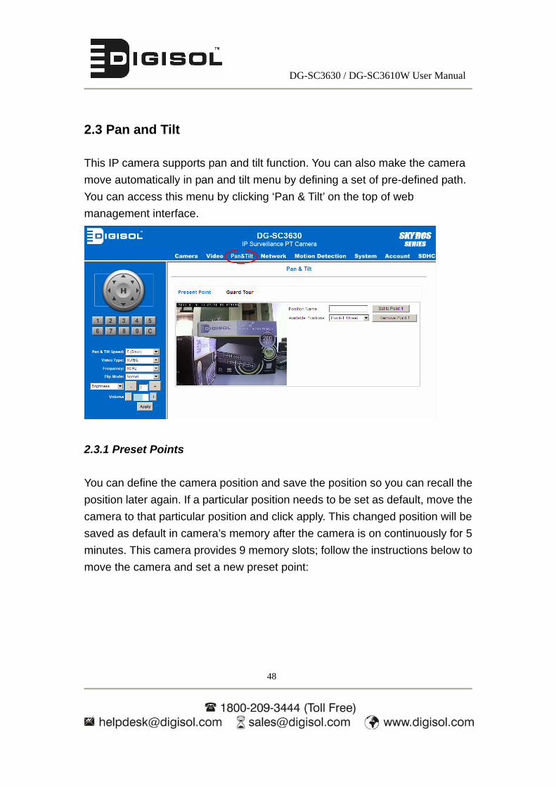
2.3 Pan and Tilt
This IP camera supports pan and tilt function. You can also make the camera
move automatically in pan and tilt menu by defining a set of pre-defined path.
You can access this menu by clicking ‘Pan & Tilt’ on the top of web
management interface.
2.3.1 Preset Points
You can define the camera position and save the position so you can recall the
position later again. If a particular position needs to be set as default, move the
camera to that particular position and click apply. This changed position will be
saved as default in camera’s memory after the camera is on continuously for 5
minutes. This camera provides 9 memory slots; follow the instructions below to
move the camera and set a new preset point:

DG-SC3630 / DG-SC3610W User Manual
49
1. Select a memory slot from ‘Available Positions’ dropdown menu first.
2. To move the camera, click the position of labeled text (not shown on image)
on the image to move the camera to the direction. You may need to set the
Pan / Tilt speed to a slower setting, so you can move the camera in a more
accurate manner.
3. When you move the camera to the position you want, type a name in
‘Position name’ field, and click ‘Set to Point n’ (where ‘n’ is the number of
memory slots) button to save the position to selected memory slot.
After you set the position, you can recall the position from ‘Camera’ menu (click
the position number button), and the camera will move to preset position
instantly.
If you want to remove a preset position, select the memory slot from ‘Available
Positions’ dropdown menu, and then click ‘Remove Point n’, (where ‘n’ is the
number of memory slots you wish to clear position setting).
UP
DOWN
RIGHT LEFT
UPPERRIGHT
LOWERRIGHT
UPPER LEFT
LOWER LEFT

DG-SC3630 / DG-SC3610W User Manual
50
2.3.2 Guard Tour
You can make the camera move between many pre-defined positions, and
define the time you wish to pause at every position; this is called as ‘Guard
Tour’.
Before you can use this function, you have to define at least 2 positions in
‘Preset Points’ section (refer to previous section for detailed information).
The description of every setting in this menu will be given below:
Item Description Add Add a new set of guard tour
Edit Edit a selected guard tour. The parameters for an existing
guard tour will be recalled and you can modify them.
Start / Stop Select a guard tour and click this button to start guard
tour, click again to stop it. Next, go to ‘Camera’ menu to
see it in action. Only one guard tour can be activated at
the same time.
Remove Remove a guard tour from the list.

DG-SC3630 / DG-SC3610W User Manual
51
If you wish to add a new set of guard tour, click ‘Add’ to add a new guard tour set
as shown below:
When the above screenshot appears do the following:
1. First enter a name for the guard tour being added.
2. Next, select a preset point from the list of available positions and click on
add to list. Once this is done, a record will appear below with the ‘view time’
as ‘10 seconds’ (by default) and ‘view order’ as ‘1’.
3. Then, without clicking on save, select the next preset point of the guard
tour (in the same window), give it a different name and then click on add to
list. Once done, another record will appear. The ‘view order’ parameter
value here will be ‘2’ automatically.
Once all the preset points have been added in the guard tour list, you can edit
the parameters of ‘view time’ if you wish and then save the settings again. Note
that no two records in the guard tour list can have the same value for ‘view
order’. The guard tour will start visiting positions by order. (From ‘1’ to last
number, and then start from ‘1’ again)

DG-SC3630 / DG-SC3610W User Manual
52
The description of every setting in this menu will be given below:
Item Description Name Input the name of this set of guard tour here. As you may
have many sets of guard tour, please give it a meaningful
name so you can remember the main purpose of this set.
View with random
order
Does not visit all positions in the guard tour by order; visits
them randomly instead.
Available
positions
Select preset points from dropdown menu here, then click
‘Add to list’ to add this position to this guard tour.
When you click ‘Add to list’, you’ll be prompted to set these
parameters:
View Time: Define the time you wish the camera to stop at
this position in seconds.
View Order: Define the number that decides the order of
visiting the positions set in the guard tour.
Remove: Remove this position from list.

DG-SC3630 / DG-SC3610W User Manual
53
Save: Save settings for this position.
Close: Close this window and discard all changes.
2.4 Network Settings
All network-related settings can be found in this menu, and you have to specify
TCP/IP parameters in this menu if you want to change IP address, use PPPoE,
Dynamic DNS, activate UPnP and configure Loginfree, RTSP feature.
You can access this menu by clicking ‘Network’ on the top of web management
interface.
After you select ‘Network’, network setting menu will appear. There are 5
sub-menus for Wired model (DG-SC3630) as shown below:

DG-SC3630 / DG-SC3610W User Manual
54
Similarly, for Wireless model (DG-SC3610W) 6 sub-menus will be displayed as
shown below.
Please click the network setting you wish to set, and then refer to instructions
given below:

DG-SC3630 / DG-SC3610W User Manual
55
2.4.1 LAN
You can define IP address and select the port number you wish to use here.
The description of every setting in this menu will be given below:
Item Description Network Type This camera can obtain the IP address from DHCP server
automatically (if you have one), or set a fixed IP address.
Select ‘DHCP’ to obtain IP address automatically or ‘Static
IP Address’ to assign this IP camera with a fixed IP
address.
When ‘DHCP’ is selected, IP address parameters below
will be grayed out.
IP Address Specify the IP address for this IP camera here.

DG-SC3630 / DG-SC3610W User Manual
56
Subnet Mask Specify the subnet mask for this IP camera here.
Gateway Specify the gateway address of the local network here.
Primary DNS Specify the IP address of DNS server here. Please input
IP address only. If you don’t know the address of DNS
server, ask network administrator or your ISP for help.
Secondary DNS Specify the IP address of backup DNS server here. When
primary DNS is unreachable, IP camera will use the IP
address specified here as DNS server.
This field is optional.
HTTP Port Specify the port number of web management interface
here. If it’s not 80, you’ll have to add ‘:port’ after the IP
address / hostname of this IP camera in the address bar
of Internet explorer.
For example, if the HTTP port number you specified here
is 90 and the IP address of IP camera is 10.20.20.30, then
you have to input ‘http://10.20.20.30:90’ in the address
bar of Internet explorer.
Enable PPPoE Select ‘Enable’ to activate PPPoE function of this IP
camera, select ‘Disable’ to disable it.
User Name Input the PPPoE username assigned by your ISP here.
Password Input the PPPoE password assigned by your ISP here.
MTU Input the MTU (Maximum Transmission Unit) given by
your ISP here. Ask your ISP if you don’t know what value
you should input here. Default value ‘1392’ should work
with most of ISPs and will give you a nice network
performance.
(Available range for MTU is 512<=MTU value<=1492)
Click ‘Apply’ to save settings and make the new settings take effect.

DG-SC3630 / DG-SC3610W User Manual
57
2.4.2 WLAN
If you are using a wireless model of PAN/ Tilt camera, these are the parameters
that need to be set to connect to the wireless network

DG-SC3630 / DG-SC3610W User Manual
58
The description of every setting in this menu will be given below:
Item Description Wireless Connection Select ‘Enable’ to activate wireless network function of
this IP camera, select ‘Disable’ to disable it.
Network Type Select the network type of wireless connection.
Available options are ‘Infrastructure’ (Connect the IP
camera to a wireless access point), and ‘Adhoc’ (This
IP camera will become a stand-alone wireless network
point, other wireless computers / devices can discover
this IP camera and connect to it without wireless
access point).
You can set to ‘Adhoc’ when you don’t have any
wireless access point, but your computer has wireless
network card. Set to ‘Infrastructure’ when you have
wireless access point, and you have computers with
wired/wireless network connection.
Available Networks Shows all wireless access points found by this IP
camera. Please note not all access points will be
displayed at the same time, if the access point you
expected to connect does not appear, you may have
to click ‘Refresh’ button for some time until it appears.
The description of every field is listed below:
Connect: You can select the wireless access point you
wish to connect here.
SSID: the SSID of all found wireless access points will
be shown here. Some wireless access points may
hide their SSID; in this case, you have to identify them
by their MAC address.
DG-SC3630 / DG-SC3610W User Manual
59
MAC Address: If there are many wireless access
points in proximity or if some wireless access point
hides its SSID, you can use MAC address to
distinguish them.
Signal: Shows the radio signal strength.
Channel: Shows the radio channel of this wireless
access point.
Encryption: Shows the encryption type used by this
wireless access point. You must use the same
encryption type if you wish to connect to a certain
wireless access point. If the wireless access point
does not use encryption, ‘Disabled’ will be displayed
here.
Network Type: Shows the network type of a certain
wireless access point (Infrastructure or Adhoc).
SSID Input the SSID of the wireless access point you wish to
connect. It should be less than 32 alphanumerical
characters.
When you select a wireless access point above, its
SSID will be filled in this field automatically. However,
if the SSID is not displayed (the wireless access point
you selected chooses to hide its SSID), you have to
know its SSID and input it here, or you will not be able
to connect it.
Channel Select the radio channel you wish to use here. When
network type is ‘Infrastructure’, the radio channel is
auto-selected according to the channel that wireless
access point uses. You can only select the channel
number when network type is ‘Adhoc’.
DG-SC3630 / DG-SC3610W User Manual
60
Authentication Here you can select the authentication type of your
wireless network.
None: When no authentication is required by your
wireless network then select “None”.
Open System: Open system authentication type does
not provide authentication. It provides identification
using the IP Camera MAC address.
Shared Key System: Shared Key System
authentication type is a process in which IP Camera
can gain access to a wireless network by using Wired
Equivalent Privacy (WEP) protocol.
WPA-PSK: WPA-PSK is an authentication mechanism
in which users need to enter a key for accessing a
wireless network.
WPA2-PSK: This mode is designed for home and
small office networks that don't require the complexity
of an 802.1X authentication server. Each wireless
network device encrypts the network traffic using a
256 bit key
WPA None: This mode is available only for Adhoc
mode and it functions similar to WPA-PSK.
Encryption WEP: When WEP is selected (either in Open system
or Shared key system) then you need to enter either
Hex or ASCII characters as a wireless key.
TKIP: It is a wireless encryption algorithm used with
WEP, WPA/PSK.
DG-SC3630 / DG-SC3610W User Manual
61
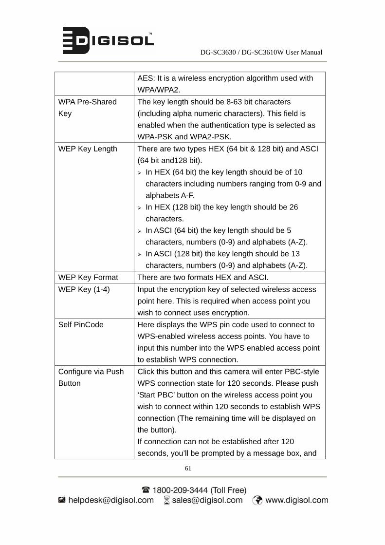
AES: It is a wireless encryption algorithm used with
WPA/WPA2.
WPA Pre-Shared
Key
The key length should be 8-63 bit characters
(including alpha numeric characters). This field is
enabled when the authentication type is selected as
WPA-PSK and WPA2-PSK.
WEP Key Length There are two types HEX (64 bit & 128 bit) and ASCI
(64 bit and128 bit).
In HEX (64 bit) the key length should be of 10
characters including numbers ranging from 0-9 and
alphabets A-F.
In HEX (128 bit) the key length should be 26
characters.
In ASCI (64 bit) the key length should be 5
characters, numbers (0-9) and alphabets (A-Z).
In ASCI (128 bit) the key length should be 13
characters, numbers (0-9) and alphabets (A-Z).
WEP Key Format There are two formats HEX and ASCI.
WEP Key (1-4) Input the encryption key of selected wireless access
point here. This is required when access point you
wish to connect uses encryption.
Self PinCode Here displays the WPS pin code used to connect to
WPS-enabled wireless access points. You have to
input this number into the WPS enabled access point
to establish WPS connection.
Configure via Push
Button
Click this button and this camera will enter PBC-style
WPS connection state for 120 seconds. Please push
‘Start PBC’ button on the wireless access point you
wish to connect within 120 seconds to establish WPS
connection (The remaining time will be displayed on
the button).
If connection can not be established after 120
seconds, you’ll be prompted by a message box, and

DG-SC3630 / DG-SC3610W User Manual
62
you can press ‘Start PBC’ button to try again.
Configure via
PinCode
If you have wireless access point’s WPS PIN code,
you can input it here and press ‘Start PIN’ button to
start to establish PIN-style WPS connection.

DG-SC3630 / DG-SC3610W User Manual
63
2.4.3 Dynamic DNS
If your ISP does not give you a fixed Internet IP address (i.e. the Internet
address you’re using when you access the Internet is not always the same –
ask your ISP for detailed information), you can use this function to help you
locate the IP address of this IP camera when you’re away from home or office.
Before you can use this function, you’ll need to apply for an account at
dyndns.org (http://www.dyndns.org). Detailed instructions of how to apply a
new account can be found on dyndns.org’s website. (Refer section 4.3 to obtain
a free Dyndns account).
The description of every setting in this menu will be given below:
Item Description Enable DDNS Select ‘Enable’ to activate Dynamic DNS function of this
IP camera, select ‘Disable’ to disable it.
Provider Select dynamic DNS service provider here. Only
dyndns.org is available currently.
Host Name Input dynamic DNS host name here.
User Name Input dynamic DNS user name here, must be the same as
the one you applied on dyndns.org.
Password Input dynamic DNS password here, must be the same as
the one you applied on dyndns.org.
Click ‘Apply’ to save settings and make the new settings take effect.
DG-SC3630 / DG-SC3610W User Manual
64
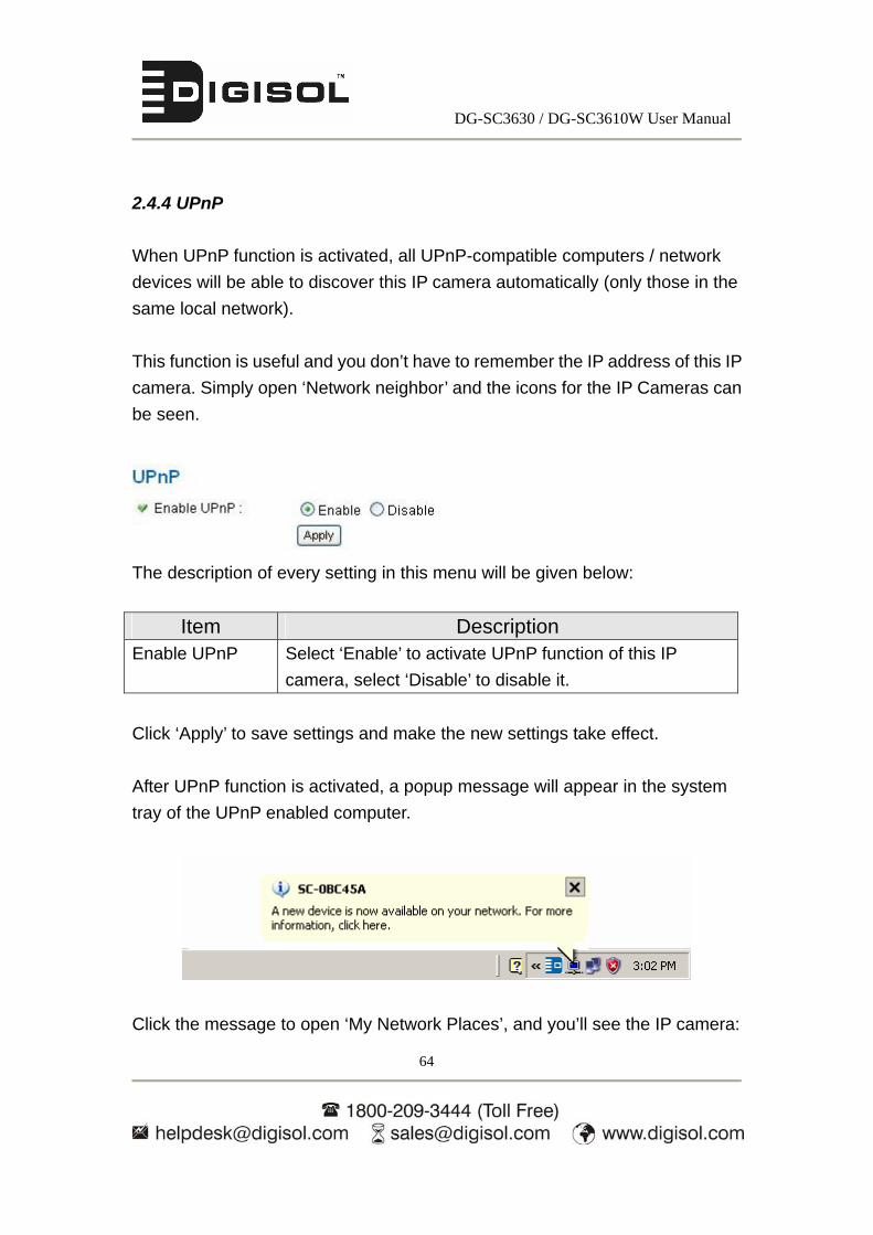
2.4.4 UPnP
When UPnP function is activated, all UPnP-compatible computers / network
devices will be able to discover this IP camera automatically (only those in the
same local network).
This function is useful and you don’t have to remember the IP address of this IP
camera. Simply open ‘Network neighbor’ and the icons for the IP Cameras can
be seen.
The description of every setting in this menu will be given below:
Item Description Enable UPnP Select ‘Enable’ to activate UPnP function of this IP
camera, select ‘Disable’ to disable it.
Click ‘Apply’ to save settings and make the new settings take effect.
After UPnP function is activated, a popup message will appear in the system
tray of the UPnP enabled computer.
Click the message to open ‘My Network Places’, and you’ll see the IP camera:

DG-SC3630 / DG-SC3610W User Manual
65
You can double-click the icon to launch Internet Explorer and log onto IP
camera’s web management interface directly.
DG-SC3630 / DG-SC3610W User Manual
66
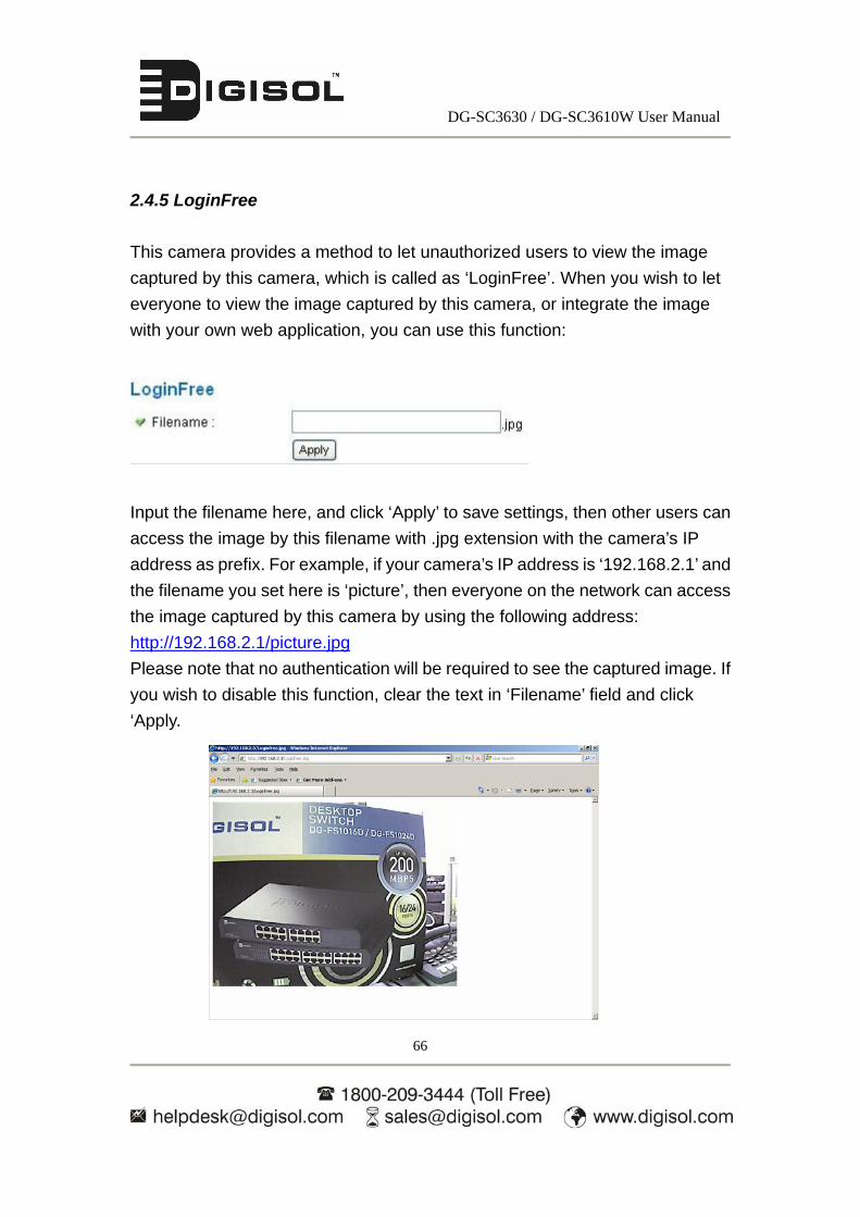
2.4.5 LoginFree
This camera provides a method to let unauthorized users to view the image
captured by this camera, which is called as ‘LoginFree’. When you wish to let
everyone to view the image captured by this camera, or integrate the image
with your own web application, you can use this function:
Input the filename here, and click ‘Apply’ to save settings, then other users can
access the image by this filename with .jpg extension with the camera’s IP
address as prefix. For example, if your camera’s IP address is ‘192.168.2.1’ and
the filename you set here is ‘picture’, then everyone on the network can access
the image captured by this camera by using the following address:
http://192.168.2.1/picture.jpg
Please note that no authentication will be required to see the captured image. If
you wish to disable this function, clear the text in ‘Filename’ field and click
‘Apply.

DG-SC3630 / DG-SC3610W User Manual
67
2.4.6 RTSP
If you want to watch video captured by this IP camera by your own RTSP (Real
Time Streaming Protocol) media player, you can use this function to setup
RTSP parameters, so your RTSP-compatible player will be able to receive
video data.
The description of every setting in this menu will be given below:
Item Description RTSP Port Input the port number of RTSP here. Default setting is
554.
MPEG4 RTSP
Path
Input the path of MPEG4 RTSP video file. When you use
RTSP-compatible media player to play RTSP stream,
please remember to add ‘.sdp’ file extension.
H.264 RTSP Path Input the path of H.264 RTSP video file. When you use
RTSP-compatible media player to play RTSP stream,
please remember to add ‘.sdp’ file extension.
RTP port range Input the range of RTP port here. Default setting is 50000
to 60000.

DG-SC3630 / DG-SC3610W User Manual
68
2.5 Motion Detection
When you wish to use this camera to monitor the activities, motion detection
function will be very useful. When Motion Detection is used, continuous manual
monitoring of the images from the camera is not required. The camera can
detect motions and automatically send intimations. Once motion is detected, a
captured image can be sent to you by Email or via FTP or stored in local SD
card.
To use motion detection, click the following link on the top of the menu as shown
below:
After you selected ‘Motion Detection’, a sub-menu will appear. There are 5
sub-menus available here:

DG-SC3630 / DG-SC3610W User Manual
69
2.5.1 Motion Detection
You can use this menu to setup basic motion detection settings:
The description of every setting in this menu will be given below:
Item Description Enable Motion Detection
Select ‘Enable’ to enable motion detection, and select ‘Disable’ to disable this function.
Motion Detection Interval
Select the time interval between two motions from dropdown menu. When a motion is detected, camera will not detect any motion again within the time interval you specified here. Available options are from 0 second (always detect new motion) to 60 seconds.
Recording Time Select the duration you wish this camera to record an image when a motion is detected from dropdown menu. Available options are 1, 2, 3, 4, and 5 (seconds).
DG-SC3630 / DG-SC3610W User Manual
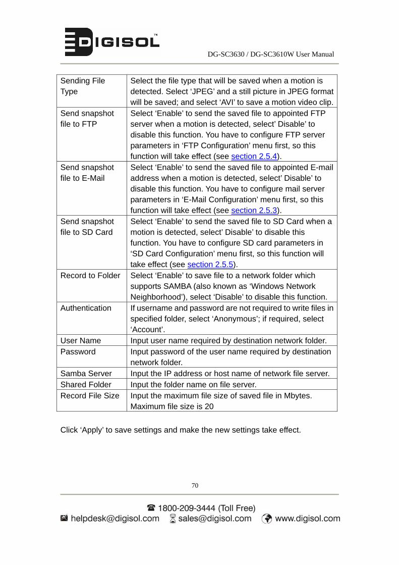
70
Sending File Type
Select the file type that will be saved when a motion is detected. Select ‘JPEG’ and a still picture in JPEG format will be saved; and select ‘AVI’ to save a motion video clip.
Send snapshot file to FTP
Select ‘Enable’ to send the saved file to appointed FTP server when a motion is detected, select’ Disable’ to disable this function. You have to configure FTP server parameters in ‘FTP Configuration’ menu first, so this function will take effect (see section 2.5.4).
Send snapshot file to E-Mail
Select ‘Enable’ to send the saved file to appointed E-mail address when a motion is detected, select’ Disable’ to disable this function. You have to configure mail server parameters in ‘E-Mail Configuration’ menu first, so this function will take effect (see section 2.5.3).
Send snapshot file to SD Card
Select ‘Enable’ to send the saved file to SD Card when a motion is detected, select’ Disable’ to disable this function. You have to configure SD card parameters in ‘SD Card Configuration’ menu first, so this function will take effect (see section 2.5.5).
Record to Folder Select ‘Enable’ to save file to a network folder which supports SAMBA (also known as ‘Windows Network Neighborhood’), select ‘Disable’ to disable this function.
Authentication If username and password are not required to write files in specified folder, select ‘Anonymous’; if required, select ‘Account’.
User Name Input user name required by destination network folder. Password Input password of the user name required by destination
network folder. Samba Server Input the IP address or host name of network file server. Shared Folder Input the folder name on file server. Record File Size Input the maximum file size of saved file in Mbytes.
Maximum file size is 20
Click ‘Apply’ to save settings and make the new settings take effect.
DG-SC3630 / DG-SC3610W User Manual
71
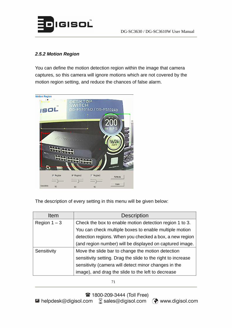
2.5.2 Motion Region
You can define the motion detection region within the image that camera
captures, so this camera will ignore motions which are not covered by the
motion region setting, and reduce the chances of false alarm.
The description of every setting in this menu will be given below:
Item Description Region 1 – 3 Check the box to enable motion detection region 1 to 3.
You can check multiple boxes to enable multiple motion
detection regions. When you checked a box, a new region
(and region number) will be displayed on captured image.
Sensitivity Move the slide bar to change the motion detection
sensitivity setting. Drag the slide to the right to increase
sensitivity (camera will detect minor changes in the
image), and drag the slide to the left to decrease
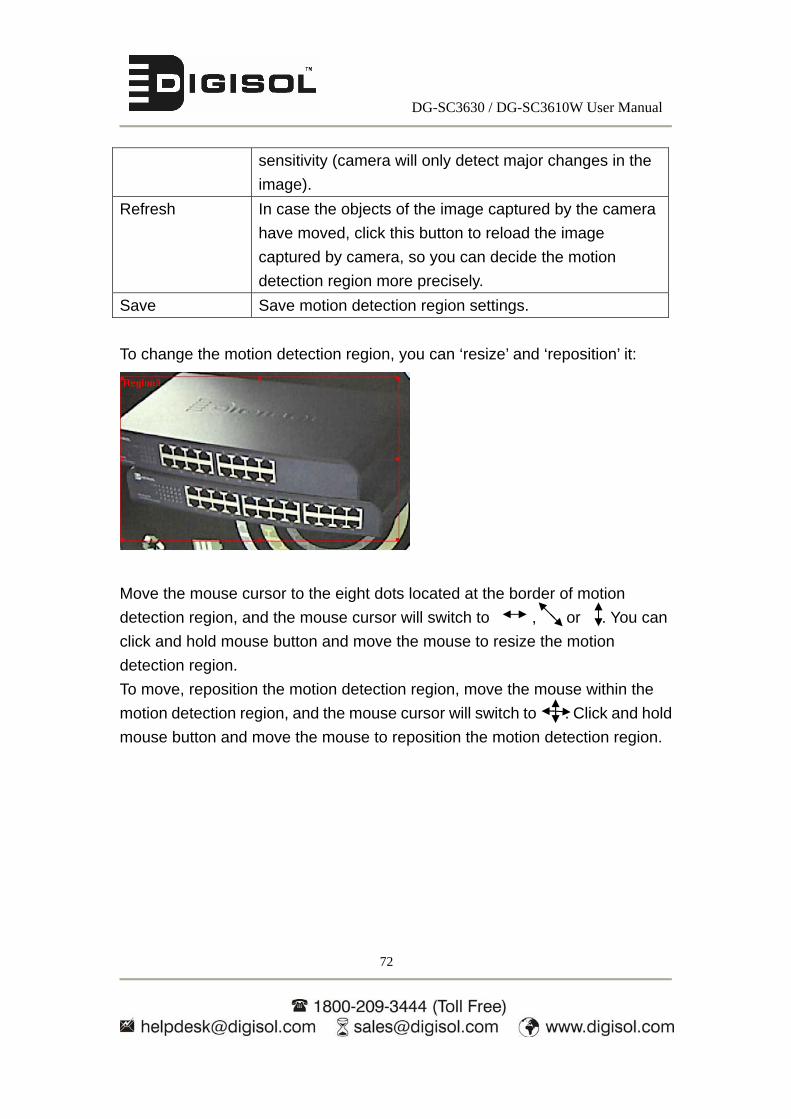
DG-SC3630 / DG-SC3610W User Manual
72
sensitivity (camera will only detect major changes in the
image).
Refresh In case the objects of the image captured by the camera
have moved, click this button to reload the image
captured by camera, so you can decide the motion
detection region more precisely.
Save Save motion detection region settings.
To change the motion detection region, you can ‘resize’ and ‘reposition’ it:
Move the mouse cursor to the eight dots located at the border of motion
detection region, and the mouse cursor will switch to , , or . You can
click and hold mouse button and move the mouse to resize the motion
detection region.
To move, reposition the motion detection region, move the mouse within the
motion detection region, and the mouse cursor will switch to . Click and hold
mouse button and move the mouse to reposition the motion detection region.

DG-SC3630 / DG-SC3610W User Manual
73
2.5.3 Email
You can define the destination address of E-mail sending and mail server
parameters here.
The description of every setting in this menu will be given below:
Item Description Recipient E-Mail
Address
Input the email recipient’s Email address here.
E-Mail Subject Specify the title of sending email, so you can identify the
mail sent from this camera from others quickly.
SMTP Server Input the IP address or host name of the SMTP server
(the server that delivers the Email for you) here.
If you don’t know, please refer to the SMTP server you’re
using in your Email software (like Outlook, Outlook
Express etc.), or ask your network administrator or ISP.
Sender E-Mail
Address
Input the Email address of mail sender, this will help you
to identify the Email sent by this IP camera by sender’s
Email address.
NOTE: Some mail server would reject to deliver the Email
from unknown sender, it’s recommended to input your

DG-SC3630 / DG-SC3610W User Manual
74
own Email address here, or any other actual one.
SMTP
Authentication
Some SMTP server requires mail senders to be
authenticated before they can send Email. If your SMTP
server requires you to do so, please select ‘Enable’, or
select ‘Disable’ to disable it. If you don’t know, please refer
to the SMTP server you’re using in your Email software
(like Outlook, Outlook Express etc.) or ask your network
administrator or ISP.
User Name Please input the user name of SMTP server here, if your
SMTP server requires the use of authentication.
Password Please input the password of SMTP server here, if your
SMTP server requires the use of authentication.
Click ‘Apply’ to save settings and make the new settings take effect.
After that, you can click ‘Send a test email’ to send a testing Email to the
address you set here, so you can make sure the setting you specified here is
correct and working.

DG-SC3630 / DG-SC3610W User Manual
75
2.5.4 FTP Configuration
You can set FTP server’s parameters here.
The description of every setting in this menu will be given below:
Item Description FTP Server Input the IP address or host name of the FTP server you
wish to use here.
FTP Port Input the port number of the FTP server you wish to use here.
Default port no. is 21.
User Name Input the user name of the FTP server you wish to use
here.
Password Input the password of the FTP server you wish to use
here.
Remote Folder Input the remote folder name on the FTP server here. If
nothing is specified here, all uploaded image files will be
placed in FTP server’s root directory.
Please check with the FTP server’s administrator for the
folder name that can be used to store the images from the
IP Camera. This is required as certain folders in the FTP
servers may be secured with access (read/write)
permissions
Passive Mode Select ‘Enable’ to use passive mode to send file, or select
‘Disable’ not to use passive mode to send file.
DG-SC3630 / DG-SC3610W User Manual
76
Some FTP servers require passive mode, if you don’t
know, please ask FTP server’s administrator; most of FTP
servers will work fine with both modes, but if you find that
non-passive mode is not working, you can try to use
passive mode.
Click ‘Apply’ to save settings and make the new settings take effect.
After that, you can click ‘Upload a test file’ to send a file to the FTP server you
set here, so you can make sure the setting you specified here is correct and
working.
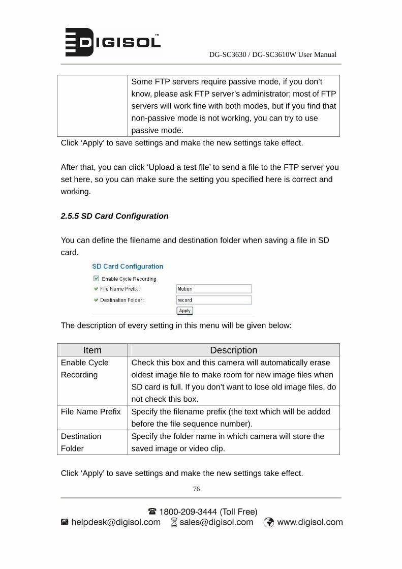
2.5.5 SD Card Configuration
You can define the filename and destination folder when saving a file in SD
card.
The description of every setting in this menu will be given below:
Item Description Enable Cycle
Recording
Check this box and this camera will automatically erase
oldest image file to make room for new image files when
SD card is full. If you don’t want to lose old image files, do
not check this box.
File Name Prefix Specify the filename prefix (the text which will be added
before the file sequence number).
Destination
Folder
Specify the folder name in which camera will store the
saved image or video clip.
Click ‘Apply’ to save settings and make the new settings take effect.

DG-SC3630 / DG-SC3610W User Manual
77
2.6 System Info
You can use this menu to get the operational information of this camera:
After you selected ‘System Info.’, a sub-menu will appear. There are 4
sub-menus available here:

DG-SC3630 / DG-SC3610W User Manual
78
2.6.1 Camera Information
Camera information allows you to set the name and administrator’s password
of this camera.
The description of every setting in this menu will be given below:
Item Description Camera Name Please specify the name of this IP Camera here. This can
be used to identify your camera on the network when you
have more than one IP camera in the same network.
Default name begins with ‘SC- ‘plus the last 6 characters
of the MAC address of this IP camera. You can modify the
name to the one you can remember and meaningful to
you, but never give all IP cameras in the same network
with same name.
Password Please specify the password here. (The one you need
when you log onto web management interface by using
‘admin’ as user name)
Confirm
Password
Please input the same password again, to make sure
there’s no typographical error.
Click ‘Apply’ to save settings and make the new settings take effect.

DG-SC3630 / DG-SC3610W User Manual
79
2.6.2 Date / Time Setting
This setting allows you to change the date and time of the built-in clock in this IP
camera. You can set the time manually, or use network time protocol (NTP) to
set the time automatically.
The description of every setting in this menu will be given below:
Item Description Set Date/Time
manually / NTP
Server
If you select ‘Set Date/Time manually’, you can set the
date and time of this camera manually. Please input the
date and time you wish to set here.
Date / time format is YYYY / MM / DD HH:MM:SS
Time is in 24-hour format.
You can click ‘Synchronize to PC time’ to use the time of
the computer you are using.
Example: 24th August 2007 = 2007/ 08 / 24,
and PM 9:24:30 = 21:24:30
If you select ‘NTP Server’, the camera will get the date
and time from NTP Server automatically.
Time Zone Please select the time zone of the country / city of resident
DG-SC3630 / DG-SC3610W User Manual
80
from dropdown menu here.
NTP Server Please input the IP address or host name of NTP server
here. You can use default value ‘pool.ntp.org’, or ask your
ISP for the IP address or host name, if they have one.
Daylight Saving
Time
The usage of this feature depends on the (country) location
in which it is being used. If the location in which the camera
is being used requires daylight saving, select ‘Yes’;
otherwise select ‘No’.
Synchronize to
PC time
Click to input current time of your computer to ‘Set Date /
Time manually’ field.
Click ‘Apply’ to save settings and make the new settings take effect.
If you wish to use the date and time setting of the computer which is connecting
to the camera, click ‘Synchronize to PC time’ button. The date and time setting
of the computer will automatically reflect in date and time field in this page.
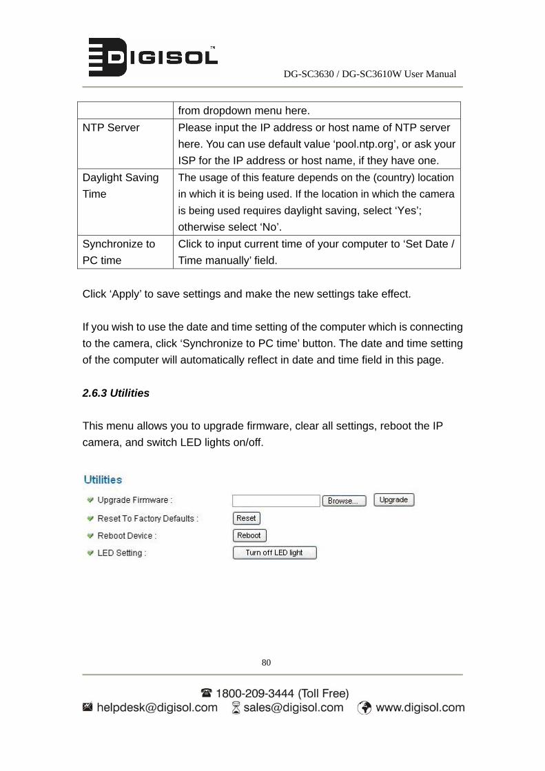
2.6.3 Utilities
This menu allows you to upgrade firmware, clear all settings, reboot the IP
camera, and switch LED lights on/off.

DG-SC3630 / DG-SC3610W User Manual
81
The description of every setting in this menu will be given below:
Item Description Upgrade
Firmware
If you have downloaded latest firmware file from our
website, you can click ’Browse’ button to select a firmware
file located on your computer’s hard drive and you can
upload the firmware file to the IP camera later.
After you selected a proper firmware file from your
computer, click ‘Upgrade Firmware’ button to start
upgrade. DO NOT DISCONNECT NOW.
If the firmware file you are loading is not a valid file of that
particular device, you’ll be prompted to select another
valid firmware file.
The IP camera will reboot after the upgrade procedure is
done.
Reset to Factory
Defaults
Clear all settings in the camera. Please think again before
you do this, and then click this button to reset all settings.
NOTE: IP address will be reset to default value
‘192.168.2.3’ also. You’ll need to change the IP address
setting of your computer if the IP address of your
computer does not begin with ‘192.168.2’, and subnet
mask is not ‘255.255.255.0’, or you’ll not be able to
connect to this IP camera.
Reboot Device If you find that the IP camera responds slowly or behaves
strange, you can click this button to try to reboot the IP
camera, this may help.
LED Setting Click ‘Turn off LED light’ button to switch the LED light of
this IP camera off, so all LEDs on the IP camera will stop
working, in case you don’t want other people to know the

DG-SC3630 / DG-SC3610W User Manual
82
camera is transferring data.
You can click this button again to switch LED lights on
again.
Click ‘Apply’ to save settings and make the new settings take effect.
2.6.4 Status
This menu provides all information about this IP camera, like firmware version,
system uptime, date / time and network information.

DG-SC3630 / DG-SC3610W User Manual
83
2.7 Account If you wish to allow other people to view the live image captured by this camera,
however you don’t want them to modify the system settings, you can give them
user-level user name and password, so they can only view the image and can
not change any system setting. When they want to click menus other than
‘Camera’, they will see the following message (marked in red in the figure below)
informing that they don’t have permission to do that.

DG-SC3630 / DG-SC3610W User Manual
84
This camera supports up to 16 users (including operator/ guest accounts).
After you selected ‘Account’, you’ll be prompted to input user account
information:

DG-SC3630 / DG-SC3610W User Manual
85
The description of every setting in this menu will be given below:
Item Description User List Lists all users currently available.
Login Input the login name (user name) of this account.
Password Input the password of this user here.
Confirm
password
Input the password of this user here again for
confirmation.
Authority Select the privilege of this user: Operator (able to change
system settings) or Guest (View images only).
Add Click this button to add the account.
Modify Modify an existing user’s information. You have to select a
user from user list first.
Remove Remove an existing user. You have to select a user from
user list first.
Click ‘Apply’ to save settings and make the new settings take effect.
DG-SC3630 / DG-SC3610W User Manual
86
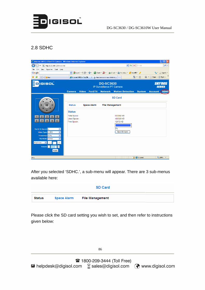
2.8 SDHC
After you selected ‘SDHC.’, a sub-menu will appear. There are 3 sub-menus
available here:
Please click the SD card setting you wish to set, and then refer to instructions
given below:

DG-SC3630 / DG-SC3610W User Manual
87
2.8.1 Status
Here shows the remaining card space for you.
2.8.2 Space Alarm
If you are using SD card to store captured image and video clip, you can set this
camera to send an E-mail when there is only little space remaining on SD card.
Please note: If you have set E-mail settings in ‘Motion Detection’ function, you
can click ‘Copy Mail Config’ button to use the same setting. However, you can
also configure a different setting here.

DG-SC3630 / DG-SC3610W User Manual
88
The description of every setting in this menu will be given below:
Item Description Recipient E-Mail
Address
Input the E-mail address to whom, you wish IP camera to
send the space alarm.
E-Mail Subject Input the title of space alarm E-mail.
SMTP Server Input the SMTP server address you wish to use to send
E-mail.
Sender E-Mail
Address
Input the Email address of mail sender, this will help you
to identify the Email sent by this IP camera by sender’s
Email address.
SMTP
Authentication
Select ‘Enable’ if the SMTP server you’re using requires
authentication, and input the username and password
below; If the SMTP server you’re using does not require
authentication, select ‘Disable’ here. If you’re not sure,
ask your ISP or network administrator.
Reserved Space Select the amount of SD card space from dropdown menu
which will be reserved and will not be used.
Click ‘Apply’ to save settings and make the new settings take effect.
You can click ‘Send a test email’ button to send a test E-Mail by the
configuration you set here.

DG-SC3630 / DG-SC3610W User Manual
89
2.8.3 File Management
You can use this menu to manage the files stored on SD card.
The description of every setting in this menu will be given below:
Item Description First Page Jump to first page of file list.
Prev Page Jump to previous page of file list.
Next Page Jump to next page of file list.
Last Page Jump to last page of file list.
Select All Select all files in this page.
Clear All Clear all files in this page.
Delete Delete selected files.
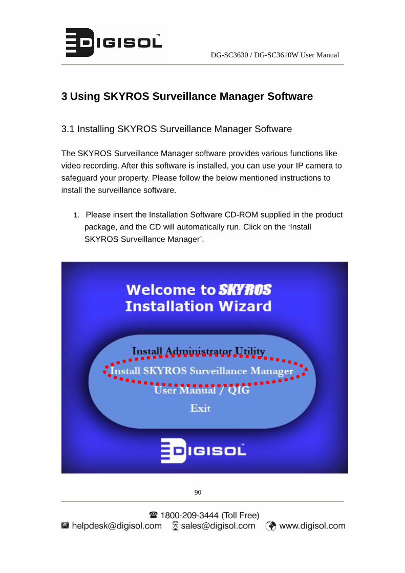
DG-SC3630 / DG-SC3610W User Manual
90
3 Using SKYROS Surveillance Manager Software
3.1 Installing SKYROS Surveillance Manager Software
The SKYROS Surveillance Manager software provides various functions like
video recording. After this software is installed, you can use your IP camera to
safeguard your property. Please follow the below mentioned instructions to
install the surveillance software.
1. Please insert the Installation Software CD-ROM supplied in the product
package, and the CD will automatically run. Click on the ‘Install
SKYROS Surveillance Manager’.

DG-SC3630 / DG-SC3610W User Manual
91
Then follow the below mentioned instructions to install SKYROS Surveillance
Manager
1. The following window appears, click ‘Next’.
2. You can specify the destination folder of software installation; you can
just use the default folder, and click ‘Next’ to continue.
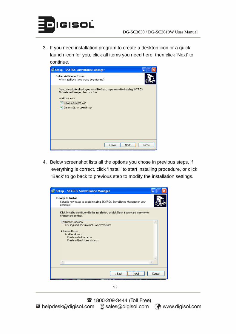
DG-SC3630 / DG-SC3610W User Manual
92
3. If you need installation program to create a desktop icon or a quick
launch icon for you, click all items you need here, then click ‘Next’ to
continue.
4. Below screenshot lists all the options you chose in previous steps, if
everything is correct, click ‘Install’ to start installing procedure, or click
‘Back’ to go back to previous step to modify the installation settings.

DG-SC3630 / DG-SC3610W User Manual
93
5. The installation procedure will take some time, please be patient.

DG-SC3630 / DG-SC3610W User Manual
94
6. When you see this window, it means the software installation procedure is
complete. Please click ‘Finish’ to finish the procedure (IP camera
surveillance software will start after you click ‘Finish’ button, if you want to
start it later, uncheck ‘Launch SKYROS Surveillance Manager’ box).

DG-SC3630 / DG-SC3610W User Manual
95
3.2 Using SKYROS Surveillance Manager software
You can click ‘SKYROS Surveillance Manager’ icon on desktop, quick launch
bar, or start menu to start the IP camera surveillance software.
Here are descriptions of all components of SKYROS Surveillance Manager
software:
Before you start:
IP camera surveillance software will only work when your monitor’s
resolution is ‘1024 x 768’. Please change the resolution before you use
IP camera surveillance software, or it won’t start.
Language
Display
layout
Full screen /
Scan
Zoom Out /
Zoom In
PTZ Control /
Home
Recording / Configure Camera /
General Option / Playback / Snap shot
Close window (stop surveillance) /
Minimize window
Video displaying
Message display box

DG-SC3630 / DG-SC3610W User Manual
96
You can put the mouse cursor on a certain component and see its button name.
A detailed description of all the buttons is mentioned in the table below:
Item Description
Video displaying
area
The image of all connected cameras will be displayed
here.
Language Select a language from this dropdown menu to change
display language.
Display layout
Change camera image display layout (Click a layout icon
to change camera display layout). There are 8 kinds of
available display layouts.
Full screen
Click this button to switch to full screen mode press ‘ESC’
key to quit full screen mode.
Scan
Click this button and the IP camera surveillance software
will switch, displaying the image of all connected cameras
automatically. Click this button once to activate scan
function (scan icon will become blue ), click again to
stop scanning (scan icon will become white ).
Zoom out
Zoom-out (To see more objects).
This function is only available for supported cameras.
Zoom In
Zoom-in (Too see more details).
This function is only available for supported cameras.
PTZ control
There are 8 directions in PTZ control ring. If the camera
you connect supports PTZ, you can use PTZ control ring
to change the direction that the camera points to.
This function is only available for supported cameras.
Home Click this button to return the camera to ‘Home’ (default)
position.

DG-SC3630 / DG-SC3610W User Manual
97
This function is only available for supported cameras.
Recording
Start video recording.
Setup
Camera configuration / Ge125
neral Options.
Playback
Playback a recorded video file.
Snapshot
Take a snapshot of current camera.
Message display Displays all system messages like camera is
disconnected etc.
Close window
(stop
surveillance)
Terminates IP camera surveillance software.
Minimize window
Minimizes IP camera surveillance software window.
Video displaying
area
Displays the images of all cameras by the display layout
you selected.

DG-SC3630 / DG-SC3610W User Manual
98
3.3 Configuring the SKYROS Surveillance Manager software
3.3.1 Configuring cameras
Before you use the SKYROS Surveillance Manager software, you must
configure the camera(s) you wish to connect. Please click ‘Setup’ button
and the below popup menu will appear:
Please select ‘Configure Cameras’ to configure cameras:
Note: If you’re prompted by a windows security alert which asks you if
you want to block ‘IPCamViewer’ program, please click ‘Unblock’
button, else the SKYROS Surveillance Manager software will not be
able to function correctly.

DG-SC3630 / DG-SC3610W User Manual
99
3.3.1.1 ‘Camera’ tab
In this tab you can configure all cameras you wish to connect. Up to 16 cameras
can be connected simultaneously:
Below are the descriptions of the settings:
Item Description
Channel Select the channel number you wish to set.
Camera Search All cameras found on your local network will be displayed
in ‘Camera Search’ box.
Select Select a camera listed in ‘Camera Search’ box, and click
‘Select’ button to automatically fill all parameters of
selected camera in the configuration fields.
Refresh Rescan all cameras on your local network if you didn’t see
the camera you expected in ‘Camera Search’ box, or new

DG-SC3630 / DG-SC3610W User Manual
100
cameras that had been introduced to your local network
after last scan.
Name* Input the name of camera here. Default value is
‘SC-xxxxxx’, where xxxxxx are the last 6 bytes of
camera’s MAC address; you can change the name of
camera as per your convenience.
Model Displays the model of selected camera, this field can not
be changed.
IP* Input the IP address of camera.
Username* Input the user name of camera.
Web Port* Input the web port of the camera. By default it is ‘80’.
Password Input the password of camera. Default value is ‘1234’.
Video Format** Select the video encoding format of this camera (MJPEG,
H.264 or MPEG4).
Reset Clear all fields in ‘Camera Configuration’ section.
OK Save settings in this tab.
Cancel Discard all settings in this tab.
*: It is recommended to use ‘Select’ button to fill the content of this field.
**: Only available for cameras that support this function.
After you’ve configured all channels you wish to set, click ‘OK’ to save the
settings, and if everything is correct, you’ll see the camera’s image in IP camera
surveillance software’s main menu as shown below.

DG-SC3630 / DG-SC3610W User Manual
101
3.3.1.2 Schedule Recording
In this tab, schedules for recording videos captured by the IP Cameras can be
pre-defined.
Below are the descriptions of the settings:
Item Description
Channel Select the channel number you wish to schedule the
recording.
One Time
Schedules
You can specify the one-time schedule for selected
camera; this schedule will be executed once only.
New
(One Time
Schedules)
Click this button and a new window will appear:

DG-SC3630 / DG-SC3610W User Manual
102
Please specify the time duration of this one-time schedule
(the date and time of ‘From’ and ‘To’), then click ‘OK’ to
save settings.
Please note you must set a schedule that will happen in
the future, you can not set a schedule in the past.
Edit You can modify a scheduled recording item. Select a
schedule in ‘One Time Schedules’ list, and click ‘Edit’
button to edit the start and end time of this schedule.
Delete Delete a selected schedule item.
New
(Weekly
Schedules)
Click this button and a new window will appear:
You can define a recording schedule that will be executed
at the specified time of certain day(s) in a week. Please
check all weekdays that apply, and set the start time in
‘From’ field. You can set the duration of video recording in
‘Period’ field (format is HH:MM:SS), and the end time will

DG-SC3630 / DG-SC3610W User Manual
103
be calculated automatically and displayed in ‘To’ field. You
can also click ‘All Time Record’ button to define a
recording schedule that will be executed every weekday,
from 12:00:00AM to 11:59:59PM.
Click ‘OK’ to save changes.
Edit You can modify a scheduled recording item. Select a
schedule in ‘Weekly Schedules’ list, and click ‘Edit’ button
to edit the start and end time of this schedule.
Delete Delete a selected schedule item.
OK Save settings in this tab.
Cancel Discard all settings in this tab.

DG-SC3630 / DG-SC3610W User Manual
104
3.3.1.3 Audio
For cameras that support audio, you can use this tab to decide if you wish to
hear the audio captured by selected camera.
The settings are described below:
Item Description
Channel Select the channel number you wish to set.
Mute Audio Check this box and the IP camera surveillance software
will mute the live audio from the camera at that moment.
Record Video
Only
Check this box and the IP camera surveillance software
will not record the audio captured by this camera.
OK Save settings in this tab.
Cancel Discard all settings in this tab.
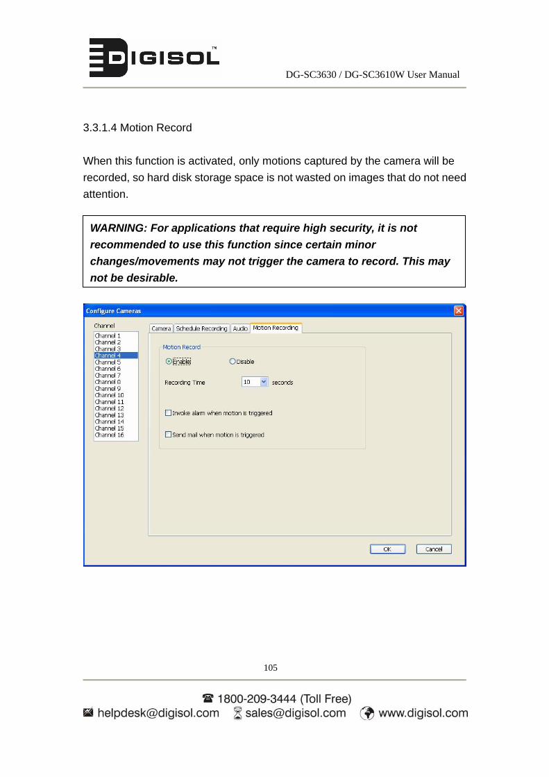
DG-SC3630 / DG-SC3610W User Manual
105
3.3.1.4 Motion Record
When this function is activated, only motions captured by the camera will be
recorded, so hard disk storage space is not wasted on images that do not need
attention.
WARNING: For applications that require high security, it is not
recommended to use this function since certain minor
changes/movements may not trigger the camera to record. This may
not be desirable.

DG-SC3630 / DG-SC3610W User Manual
106
The settings are described below:
Item Description
Channel Select the channel number you wish to set.
Enable Enable motion record function.
Disable Disable motion record function.
Recording Time Select the time duration that camera will record when a
motion has been detected from dropdown menu in
seconds.
Invoke alarm
when motion is
triggered
Send an alarm when a motion has been detected by the
camera.
Send mail when
motion is
triggered
Send an email to a pre-defined address when a motion
has been detected by the camera.
OK Save settings in this tab.
Cancel Discard all changes done in this tab.

DG-SC3630 / DG-SC3610W User Manual
107
3.3.2 General Settings
You can set system-wide settings of this IP camera surveillance software in this
menu.
3.3.2.1 ‘General’ tab
All general settings like file storage directory and recording spaces can be set
here.

DG-SC3630 / DG-SC3610W User Manual
108
The settings are described below:
Item Description
Data Directory Set the directory (folder) you wish to store the recorded
video and captured image. You can click ‘Browse’ button
to select a directory in your hard disk.
Free Recording
Space
Displays remaining storage space.
Max Video File
Size
Defines the maximum file size of each video file. When
the size of file exceeds this value, IP camera surveillance
software will open another file to record the video.
Scan Time Define the time period to pause between every camera
switch when you activate ‘Scan’ function.
Cycle Recording You can decide the behavior when hard disk space is full:
Disable: Do not overwrite recorded video files.
Enable: Overwrite recorded video files.
OK Save settings in this tab.
Cancel Discard all changes done in this tab.

DG-SC3630 / DG-SC3610W User Manual
109
3.3.2.2 ‘E-Mail Setting’ tab
If you want to use motion detection function and wish to get an email that
contains the image captured by the camera, please setup your email related
parameters here.
The settings are described here:
Item Description
E-Mail Subject Specify the subject of the email.
Recipient E-Mail
Address
This is the list of all email addresses you set.
New Click this button and you’ll be prompted to input the email
address. Click ‘OK’ to save changes.

DG-SC3630 / DG-SC3610W User Manual
110
Edit Select an email address from ‘Recipient E-Mail Address’
box, and click ‘Edit’ to edit the email address.
Delete Delete selected email address.
Sender E-Mail
Address
Specify the email address of email sender.
SMTP Server Specify the IP address or host name of the SMTP server
you wish to use. For most of ISPs they will only allow its
subscriber to use their SMTP server, if you don’t know
which SMTP server you should use, please refer to the
setting of your email software or ask your ISP / network
administrator.
SMTP port Specify the port number of the SMTP server you wish to
use here. By default (and the setting of most of the SMTP
servers) it is ‘25’.
SMTP Auth Select ‘Enable’ if your SMTP server requires
authentication, select ‘Disable’ if it’s not required. If you
don’t know if your SMTP server requires authentication,
please refer to the setting of your email software or ask
your ISP / network administrator.
SMTP Account Input the SMTP account (username) of your SMTP server
here. In most cases, it’s the same as your POP3
username (the one you use to receive email). Please refer
to the setting of your email software or ask your ISP /
network administrator if you’re not sure about this.
SMTP Password Input the SMTP password of your SMTP server here. In
most cases, it’s the same with your POP3 password (the

DG-SC3630 / DG-SC3610W User Manual
111
one you used to receive email). Please refer to the setting
of your email software or ask your ISP / network
administrator if you’re not sure about this.
OK Save settings in this tab.
Cancel Discard all changes done in this tab.
3.3.2.3 Security
If you don’t want other people to access the SKYROS Surveillance Manager
software, you can set a password to protect it.
You’ll need to input the password every time you wish to use the SKYROS
Surveillance Manager software:

DG-SC3630 / DG-SC3610W User Manual
112
To set password, please use ‘Security’ tab in ‘General Options’ menu:
The settings are described below:
Item Description
Enable Requires password authentication when this software
starts.
Disable Password authentication is not required when this
software starts.
Password Input the password you wish to use here.
Confirm
Password
Input the password you wish to use here again.
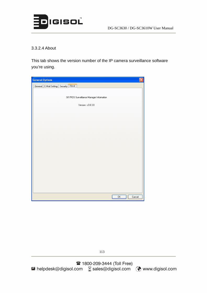
DG-SC3630 / DG-SC3610W User Manual
113
3.3.2.4 About
This tab shows the version number of the IP camera surveillance software
you’re using.
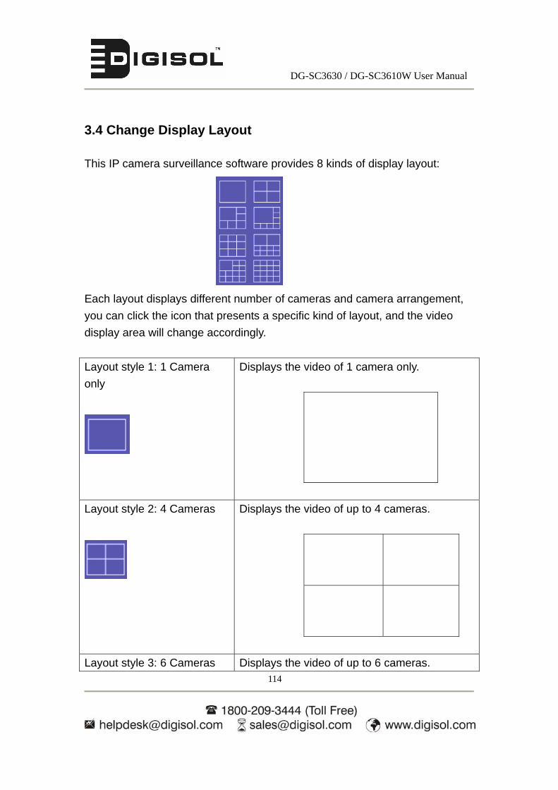
DG-SC3630 / DG-SC3610W User Manual
114
3.4 Change Display Layout
This IP camera surveillance software provides 8 kinds of display layout:
Each layout displays different number of cameras and camera arrangement,
you can click the icon that presents a specific kind of layout, and the video
display area will change accordingly.
Layout style 1: 1 Camera
only
Displays the video of 1 camera only.
Layout style 2: 4 Cameras
Displays the video of up to 4 cameras.
Layout style 3: 6 Cameras Displays the video of up to 6 cameras.

DG-SC3630 / DG-SC3610W User Manual
115
Layout style 4: 8 Cameras
Displays the video of up to 8 cameras.
Layout style 5: 9 Cameras
Displays the video of up to 9 cameras.
Layout style 6: 10 Cameras
Displays the video of up to 10 cameras.

DG-SC3630 / DG-SC3610W User Manual
116
Layout style 7: 13 Cameras
Displays the video of up to 13 cameras.
Layout style 8: 16 Cameras
Displays the video of up to 16 cameras.
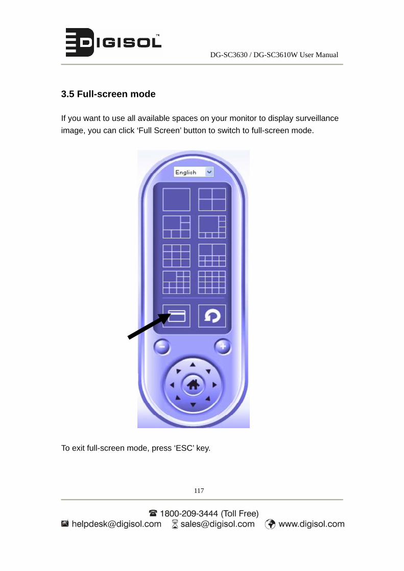
DG-SC3630 / DG-SC3610W User Manual
117
3.5 Full-screen mode
If you want to use all available spaces on your monitor to display surveillance
image, you can click ‘Full Screen’ button to switch to full-screen mode.
To exit full-screen mode, press ‘ESC’ key.

DG-SC3630 / DG-SC3610W User Manual
118
3.6 Scan
If you have more than one camera configured, and you wish to switch the
displaying image between cameras, you can click ‘Scan’ button to switch
between all configured cameras.
Click ‘Scan’ button once to activate scan function (scan icon will become
blue ), click again to stop scanning (scan icon will become white ).
NOTE: If a camera is configured but disconnected, it will still be
displayed in a scan sequence (you’ll see nothing and you’ll see
‘Disconnected’ text displayed at the upper-left corner of display
image).
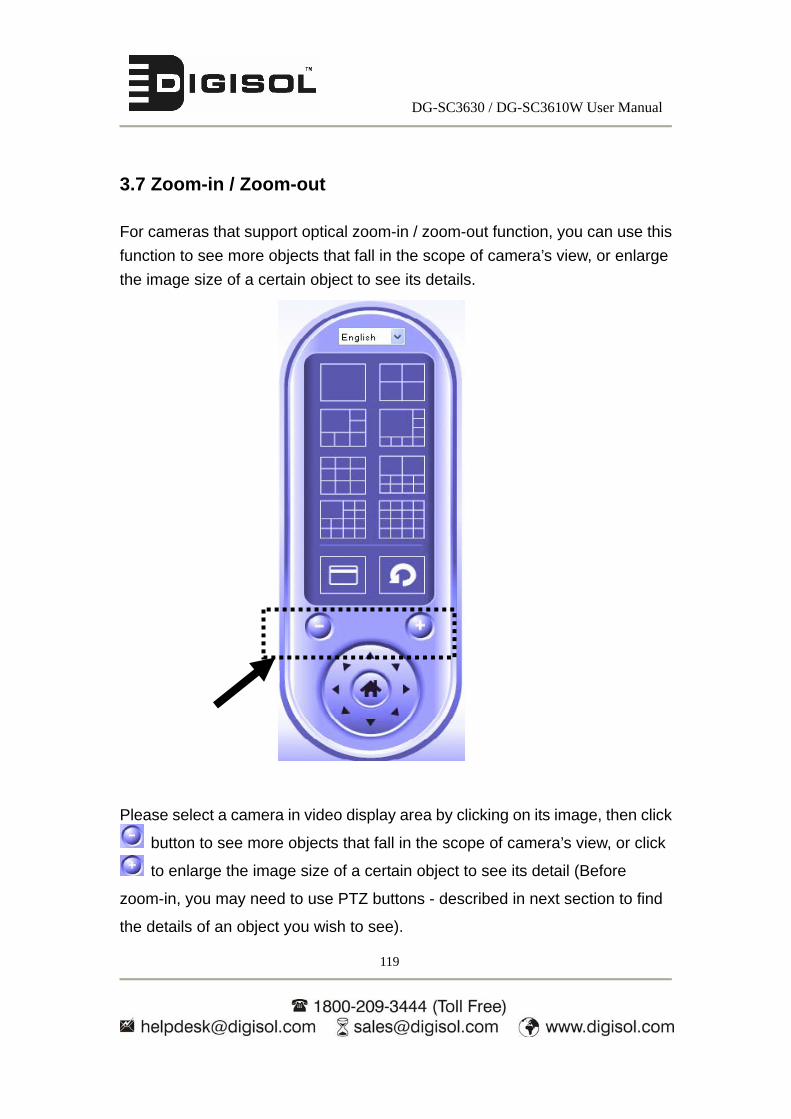
DG-SC3630 / DG-SC3610W User Manual
119
3.7 Zoom-in / Zoom-out
For cameras that support optical zoom-in / zoom-out function, you can use this
function to see more objects that fall in the scope of camera’s view, or enlarge
the image size of a certain object to see its details.
Please select a camera in video display area by clicking on its image, then click
button to see more objects that fall in the scope of camera’s view, or click
to enlarge the image size of a certain object to see its detail (Before
zoom-in, you may need to use PTZ buttons - described in next section to find
the details of an object you wish to see).

DG-SC3630 / DG-SC3610W User Manual
120
3.8 PTZ
For cameras that support pan - tilt function, you can change the position that
camera points to, to see different places that fall in the scope of camera’s view.
Please select a camera in video displaying area by clicking on its image, and
then click the directions you wish the camera to move to (total 8 directions
available). Click ‘Home’ button ( ) to return to camera’s home (default)
position.

DG-SC3630 / DG-SC3610W User Manual
121
3.9 Snapshot
You can take a snapshot of selected camera and save it to ‘Snapshot’
sub-folder of pre-defined data directory.
Click snapshot button once to take a snapshot; you can take as much
snapshots as you want before hard disk gets full.

DG-SC3630 / DG-SC3610W User Manual
122
3.10 Recording
You can start video recording of selected camera manually by clicking ‘Start
Recording’ button:
When recording starts, you’ll see a message displayed in message displaying
box like ‘1/1 10:00:00, Camera 1 Start Manual’, which means camera 1 starts
recording manually on 1/1 at 10:00:00.
To stop recording, click ‘Start Recording’ button again, and you’ll see a
message displayed in message displaying box like ‘1/1 10:00:00, Camera 1
Stop Manual’.

DG-SC3630 / DG-SC3610W User Manual
123
3.11 Video Playback
You can playback all recorded videos by clicking this button.
A new window will appear:
You have to search the video file before you can play it. There are two kinds of
video search: Time Search (searches all video files that fall in a specific period
of time) and Motion Search (searches all videos recorded by motion detection
function that falls in a specific period of time).
Please define the start and end date / time of the time period you wish to search,
and then click ‘Search’ button (of ‘Time Search’ / ‘Motion’ Search’). All found
videos will be displayed, select the video you wish to play and click ‘Play’ button
to playback.

DG-SC3630 / DG-SC3610W User Manual
124
4. Appendix
4.1 Specification
Max Resolution: 1280 x 1024 pixels
Sensor: 1.3Mega Pixel 1/4" color CMOS sensor
Gain control: Automatic
Exposure: Automatic
White Balance: Automatic
Image (Video Setting)
Image compression: MJPEG/MPEG4/H.264 Image Video
Frame rate: 10-15fps@SXGA, XGA, 30fps@QVGA, 20fps@VGA
Video resolution: MJPG&H.264: 1280x1024, 640x480, 320x240
MPEG4: 1024x768, 640x480, 320x240
System Hardware
LAN Connector: One RJ-45 port to connect to 10/100Mbps Ethernet
Wireless: IEEE 802.11b/g/n (Wireless Model Only)
LED Indicator:
Power LED, Audio LED, ACT LED and LAN LED (DG-SC3630)
Power LED, Audio LED, LAN LED and WLAN LED (DG-SC3610W)
Web GUI and SKYRO Manager Utility
Includes easy-to-use Viewer & Recorder utility
Provides Admin utility & WEB browser Management
View multiple cameras simultaneously - on PC with SKYROS surveillance
manager software Up to 16 cameras at a time
Supports up to sixteen additional user accounts for viewing camera
Auto sending Snap Shot and video by E-mail or FTP
Support DDNS and UPnP functions

DG-SC3630 / DG-SC3610W User Manual
125
Supports Windows 2000/XP/Vista/Win7
Firmware Upgradeable
4.2 Troubleshooting
If the IP camera is not working properly, before you contact the dealer of
purchase for help, please check the troubleshooting list here, this may help you
to solve the problem by yourself and therefore saves your valuable time.
Scenario Possible Solution
I cannot connect to
the IP camera
a. Please confirm the IP address setting of the
computer you’re using. If the IP Camera and the
laptop are not in the same subnet, they will not be able
to communicate with each other.
b. Please make sure you have entered the correct IP
address to connect to the IP camera.
c. If you forget the IP address of the IP camera, you
will have to reset it to factory default value (which is
192.168.2.3) by pressing ‘reset’ button on the IP
camera. You’ll need a pen or pin to be able to press
the reset button. Press and hold the reset button for 10
seconds, the IP Camera will reboot with default
settings, and then try to connect to the IP camera with
the IP address ‘192.168.2.3’.
d. Please make sure the IP camera is correctly
powered (the ‘Power’ LED should be on).
e. If you’re trying to connect to the IP camera from
Internet, please make sure the port that IP camera
uses (Video and HTTP port, see section 2.4.1) is not

DG-SC3630 / DG-SC3610W User Manual
126
blocked by firewall or other software / hardware.
f. Contact DIGISOL helpdesk, if above solutions do
not work.
Image refreshes very
slow
a. Try a higher frame rate setting, if it’s not 30.
b. Try a lower resolution.
c. If you’re connecting this camera from Internet, it
could be caused by a slow Internet connection, and it’s
not a problem caused by camera. However, when the
network connection is slow, you should use lower
frame rate / resolution.
d. Adjust the antenna if you’re using wireless
connection. The antenna should be perpendicular to
the ground to get best reception, and the distance
between IP camera and computer / wireless access
point should not be too far.
e. Try to adjust ‘MTU’ setting if you’re using PPPoE to
connect to Internet. Ask your ISP or network
administrator for detailed instruction.
IP camera is not
responding
a. Is the network cable or wireless connection
disconnected? Please check that first.
b. Unplug the power adapter from the wall socket and
plug it in again after 10 seconds, then try to connect to
the IP camera again.
c. If IP camera is correctly powered (‘Power’ LED is
on), but you still cannot connect to the camera (when
you’re sure that IP address is correct) please contact

DG-SC3630 / DG-SC3610W User Manual
127
dealer of purchase for help).
Image is fuzzy a. Adjust the focus ring on the camera until the image
becomes clear.
b. Use a soft cloth to clean the lens on the camera.
You can use moist cloth, but DO NOT use alcohol or
other chemical solution.
c. Try to adjust brightness setting.
d. If there’s any light source near the view/target area,
switch it on and see if image looks better.
I set the IP camera to
send image by Email
or FTP, but nothing
is received
a. If the image is sent by Email, please make sure it’s
not blocked by any anti-spam mechanism.
b. Please make sure you have enough permission for
FTP uploading (You can try this by clicking ‘Upload a
test file’ button).
c. Make sure the user name and / or password of
SMTP server is correct, if your SMTP server requires
authentication (You can try this by click ‘Send a test
Email’ button).
d. Please check log, if FTP upload or Email sending is
failed, it will be logged, and this may give you some
clue on how to solve the problem.
e. Change the threshold to a more sensitive setting.
I hear a strange
sound when I use
pan / tilt function
a. Please check if anything jams the camera, if so then
remove it.
b. If the camera does not respond when you’re trying

DG-SC3630 / DG-SC3610W User Manual
128
to use pan / tilt function, the servo motor inside the
camera may be dead. Please return the camera to the
dealer of purchase and ask for help.
Nothing is heard at
the camera side
when I use ‘Speak to
IPCam’ function
An external speaker is required to playback the voice
received on the computer’s side.
My player can’t play
the recorded video or
the video is played
without voice.
Please make sure you’ve installed MPEG4 decoder, if
not please download ffdshow, it’s a free open
application.

DG-SC3630 / DG-SC3610W User Manual
129
4.3 Obtain a free Dyndns account
If your ISP is issuing dynamic (non-static) IP address to you and you can’t connect to your IP camera when you’re away from it, you can follow the below steps to obtain a free Dyndns account, which will provide you free IP address to host name mapping service: 1. Launch your web browser and navigate to http://www.dyndns.org
2. Click ‘Sign In’ button (located at upper-right corner of dyndns.org’s
webpage)

DG-SC3630 / DG-SC3610W User Manual
130
3. Click ‘Create an Account’ in pop-up menu.
4. Fill all fields appearing in this menu, and click ‘Create Account’ button to create a new account. You’ll be prompted if the account you selected is not available.
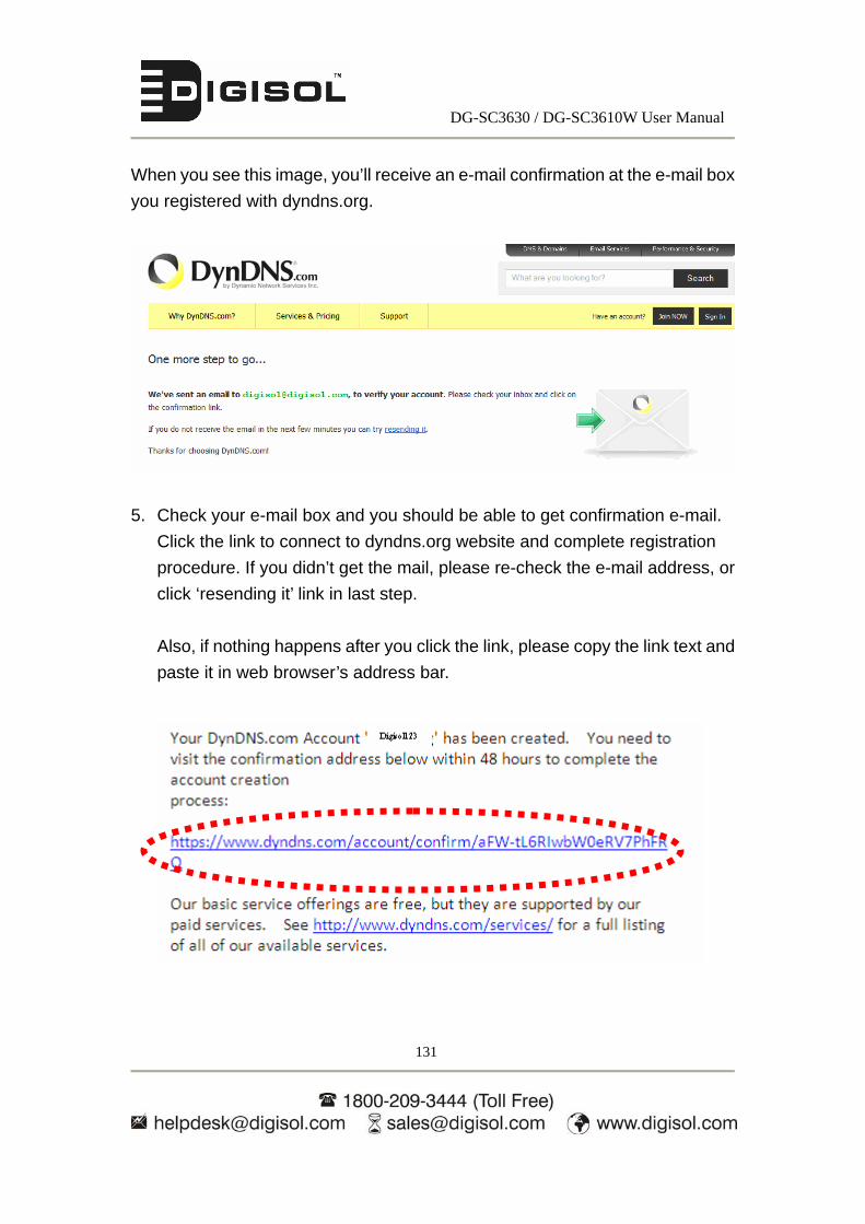
DG-SC3630 / DG-SC3610W User Manual
131
When you see this image, you’ll receive an e-mail confirmation at the e-mail box
you registered with dyndns.org.
5. Check your e-mail box and you should be able to get confirmation e-mail.
Click the link to connect to dyndns.org website and complete registration
procedure. If you didn’t get the mail, please re-check the e-mail address, or
click ‘resending it’ link in last step.
Also, if nothing happens after you click the link, please copy the link text and
paste it in web browser’s address bar.

DG-SC3630 / DG-SC3610W User Manual
132
6. When you see ‘Account Confirmed’ webpage, it indicates that your
dyndns.org account has been confirmed and activated. Now you can click
‘Create a dynamic DNS host within our Free domains’ link to continue.
7. Click ‘Create Hostname’ button.

DG-SC3630 / DG-SC3610W User Manual
133
In this page input the hostname of your choice in ‘Hostname’ field,
Select a domain name in dropdown menu,
Select ‘Host with IP address’ for ‘Service Type’,
Input current IP address in ‘IP Address’ field (or click the link below to use
detected IP address to fill this field).
8. Click ‘Add to cart’ continue. Below screen shown will appear.

DG-SC3630 / DG-SC3610W User Manual
134
9. Click ‘Proceed to checkout’ to continue.
10. Click ‘Activate Services’ to continue.
11. With this, the account digisol123.dyndns.org will be activated.
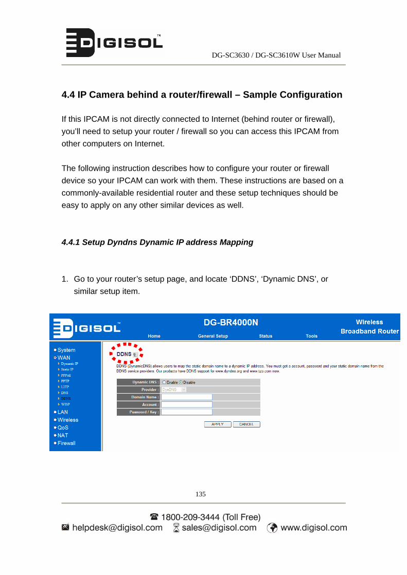
DG-SC3630 / DG-SC3610W User Manual
135
4.4 IP Camera behind a router/firewall – Sample Configuration
If this IPCAM is not directly connected to Internet (behind router or firewall),
you’ll need to setup your router / firewall so you can access this IPCAM from
other computers on Internet.
The following instruction describes how to configure your router or firewall
device so your IPCAM can work with them. These instructions are based on a
commonly-available residential router and these setup techniques should be
easy to apply on any other similar devices as well.
4.4.1 Setup Dyndns Dynamic IP address Mapping
1. Go to your router’s setup page, and locate ‘DDNS’, ‘Dynamic DNS’, or
similar setup item.
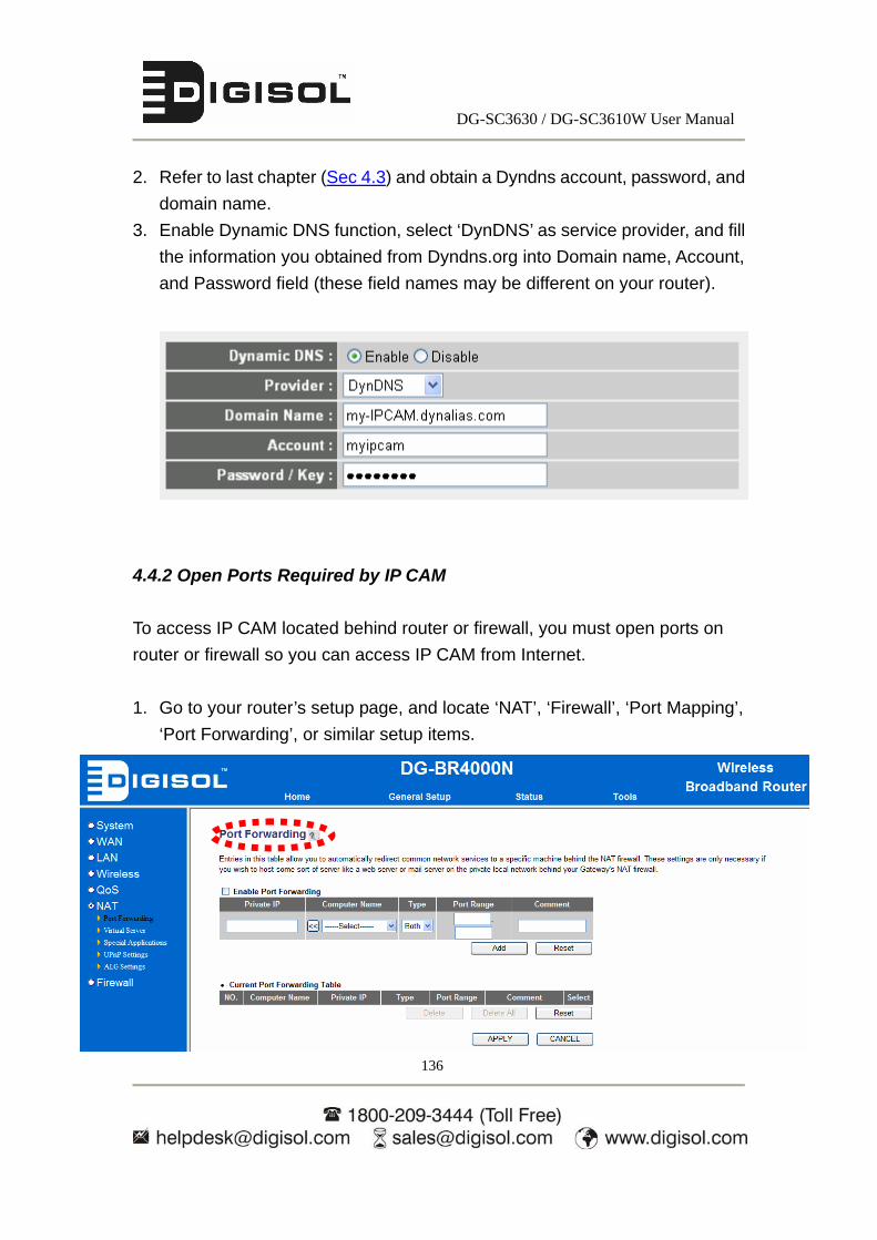
DG-SC3630 / DG-SC3610W User Manual
136
2. Refer to last chapter (Sec 4.3) and obtain a Dyndns account, password, and
domain name.
3. Enable Dynamic DNS function, select ‘DynDNS’ as service provider, and fill
the information you obtained from Dyndns.org into Domain name, Account,
and Password field (these field names may be different on your router).
4.4.2 Open Ports Required by IP CAM
To access IP CAM located behind router or firewall, you must open ports on
router or firewall so you can access IP CAM from Internet.
1. Go to your router’s setup page, and locate ‘NAT’, ‘Firewall’, ‘Port Mapping’,
‘Port Forwarding’, or similar setup items.

DG-SC3630 / DG-SC3610W User Manual
137
2. Enable this function, and fill IP CAM’s IP address in ‘Private IP’ (or similar
field), select ‘TCP’ or ‘BOTH’ as data type, and input these port numbers
given below for the services you wish to access from Internet in the port
range field.
IP CAM web configuration and view live image: 80
RTSP: 554 and 50000 to 60000
Please note that if you changed the port number of web configuration / view
or RTSP, you have to change the port forwarding setting for your router
accordingly.
4.4.3 DMZ Settings
1. If IP CAM is the only service you wish to access from Internet, you can also
use ‘DMZ’ function to access IP CAM:
Simply fill the IP address of IP CAM in Static IP field and you can access IP
CAM from the IP address of your router directly.

DG-SC3630 / DG-SC3610W User Manual
138
Corresponding settings on the IP camera for section 4.4:
In the IP CAM enter the IP address of the router in the gateway field (shown
below). Ensure that the router and IP Camera are in the same subnet.

DG-SC3630 / DG-SC3610W User Manual
139
4.5 Using Cellphone as Image Viewer
You can use your cellphone to connect to this IP CAM and view captured image.
Currently this IP CAM supports iPhone (Apple) and Google Android OS.
4.5.1 iPhone
1. Launch Safari web browser

DG-SC3630 / DG-SC3610W User Manual
140
2. Input IP CAM’s IP address / host name in safari’s address bar in the
following format:
111.222.333.444/ipcam.asp or hostname/ipcam.asp
Please note that appending ‘/ipcam.asp’ is required.

DG-SC3630 / DG-SC3610W User Manual
141
3. Input username / password to login.
4. You’ll see the image of connected camera displayed on upper-left corner of
quad-split screen. If you have more than one IP CAM, you can add other 3
IP CAMs to the quad-split screen. Click an unused corner and a yellow
square will appear to indicate that it’s being marked, then click ‘Setting’.

DG-SC3630 / DG-SC3610W User Manual
142
5. Click ‘Camera Setting’.
6. Input camera’s name, IP address, port number, username, and password in
respective field, then click ‘Done’. Please note that these fields are
case-sensitive. You can click ‘Preview’ to check connection.
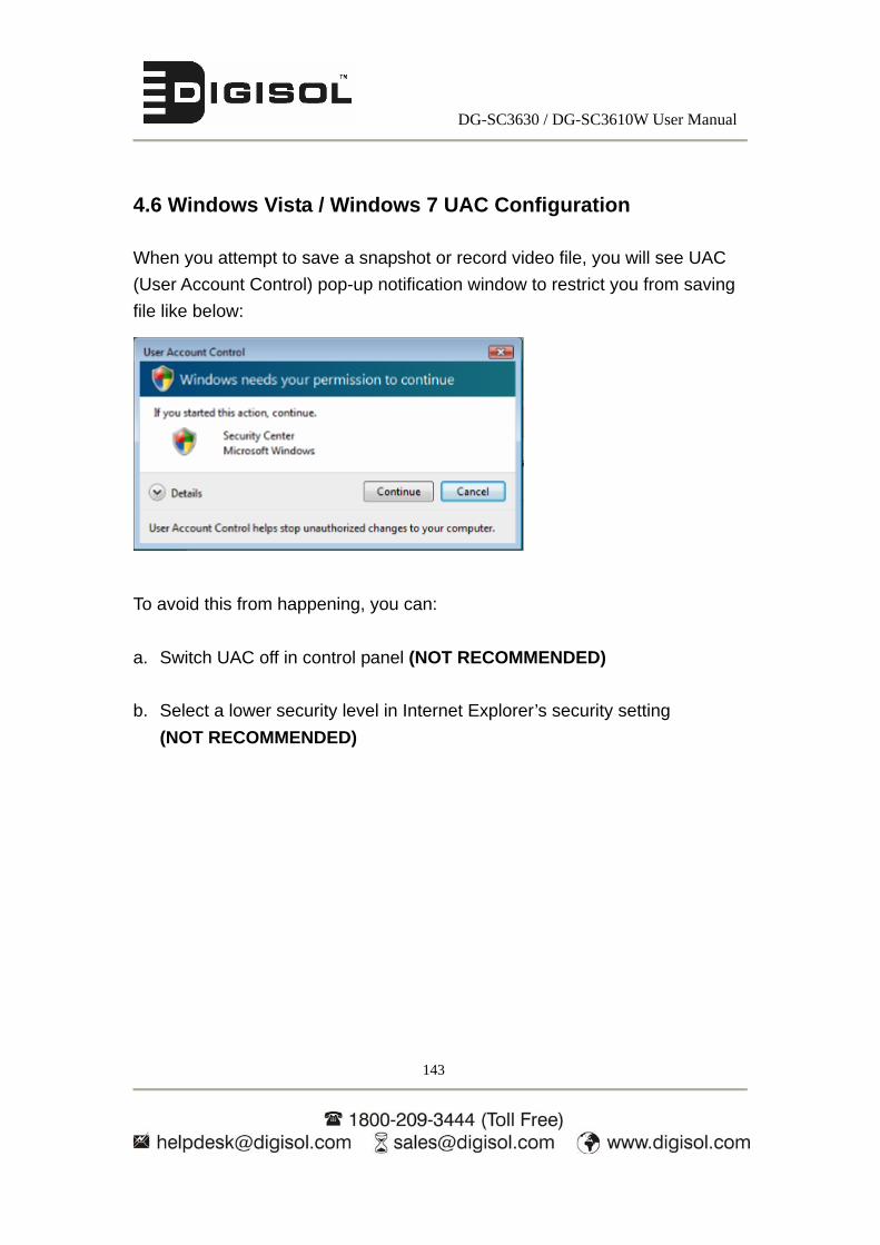
DG-SC3630 / DG-SC3610W User Manual
143
4.6 Windows Vista / Windows 7 UAC Configuration
When you attempt to save a snapshot or record video file, you will see UAC
(User Account Control) pop-up notification window to restrict you from saving
file like below:
To avoid this from happening, you can:
a. Switch UAC off in control panel (NOT RECOMMENDED)
b. Select a lower security level in Internet Explorer’s security setting
(NOT RECOMMENDED)

DG-SC3630 / DG-SC3610W User Manual
144
c. Add IP Camera’s IP address to ‘Trusted sites’ in Internet Explorer’s
security setting (RECOMMENDED)
Input IP CAM’s IP address here

DG-SC3630 / DG-SC3610W User Manual
145
d. If you don’t want to change Internet explorer’s security setting, you can run
Internet explorer as administrator as workaround.
DG-SC3630 / DG-SC3610W User Manual
146
Glossary
MJPG: Motion JPEG or M-JPEG is a digital video sequence that is made up of a
series of individual JPEG images. (JPEG stands for Joint Photographic Experts Group).
The quality of the image is guaranteed, regardless of movement because the captured
video is a series of separately compressed JPEG images that can be extracted
individually. The compression level can be adjusted to control image quality and file
size.
MPEG4: is a video and audio compression technology found in many IP network
camera models. The MPEG4 compression standard aims to deliver superior image
quality while optimizing bandwidth.
H.264: H.264 is the latest compression technology that significantly reduces the file
size of high-quality video images. Offers higher video resolution than Motion JPEG or
MPEG-4 at the same bit rate and bandwidth, or the same quality video at a lower bit
rate.
WEP (Wired Equivalent Privacy): A wireless security protocol, specified in the
IEEE 802.11 standard, which is designed to provide a wireless local area network
(WLAN) with a level of security and privacy comparable to that usually expected of a
wired LAN.
WPA (Wi-Fi Protected Access): is a data encryption specification for 802.11
wireless networks that replaces the weaker WEP. It is the most advanced encryption
method since it uses dynamic keys, Extensible Authentication Protocol to secure
enterprise network access, and an encryption method called Temporal Key Integrity
Protocol (TKIP) to secure data transmissions.
PPPoE (Point-to-Point Protocol over Ethernet): Is a network protocol for
encapsulating Point-to-Point Protocol (PPP) frames inside Ethernet frames.
DG-SC3630 / DG-SC3610W User Manual
147
TCP / IP (Transmission Control Protocol/ Internet Protocol): TCP is used
along with the Internet Protocol (IP) to transmit data as packets between computers
over the network. TCP is a connection-oriented protocol, which means that a
connection is established between the two end-points and is maintained until the data
has been successfully exchanged between the communicating applications.
DDNS (Dynamic DNS): Used to create a fixed domain name for dynamic internet ip
address. A domain name is a meaningful and easy-to-remember name for an Internet
address. Normally used when the ISP has provided you with dynamic internet ip
address to access the camera remotely.
SMTP (Simple Mail Transfer Protocol): SMTP is used for sending and receiving
e-mail. SMTP authentication is an extension of SMTP, whereby the client is required to
log into the mail server before or during the sending of email. It can be used to allow
legitimate users to send email while denying the service to unauthorized users, such as
spammers.
FTP (File Transfer Protocol): FTP is an application protocol that uses the TCP/IP
protocols, used to exchange files between computers/devices on networks. Network
cameras with embedded operating systems use FTP to send camera images to an
authorized user’s computer or web site.
UPnP (Universal Plug & Play): A set of computer network protocols that allow
the automatic peer-to-peer detection of devices on the network. Allows the discovery
of UPnP- enabled devices in a network environment.
RTSP (Real Time Streaming protocol): RTSP is a control protocol for Internet
streaming of audio and video. Mostly used for remote viewing of live or stored
security camera video over the Internet. RTSP can be considered as a “remote control”
for controlling the media stream delivered by a media server. RTSP servers typically
use RTP as the protocol for the actual transport of audio/video data.

DG-SC3630 / DG-SC3610W User Manual
148
CMOS Sensor (Complimentary metal-oxide semiconductor): Is an image
sensor available in many IP network cameras with less circuitry hence consumes
less power, produces higher frame rate & is less costly as compared to CCD
sensors.
IR LED (Infrared LED): Infrared radiation is radiation at a longer wavelength
than visible light, which means it cannot be seen by the naked eye. These cameras
are well suited for surveillance of low light areas or areas with no light at all.
Infrared LED's surround the lens and shine infrared light, illuminating the scene.
Pan/Tilt: IP cameras with panning capabilities can move back and forth
horizontally in order to monitor wider areas. In many cases a camera's panning
functionality can be controlled remotely from network PC using video
management software. Tilt refers to an IP camera's ability to be directed up and
down in a vertical plane. The camera lens can be aimed at a specific part of a scene,
and in many cases the tilt can be controlled remotely.
Frame Rate: The frame rate is used to describe the frequency at which a video
stream is updated is measured in frames per second (fps). If you want more
accurate video then the frame rate should be kept high. Lower the frame rate, lesser
the image details.
Gain Control: When camera produces a quality picture, it needs a sufficient
amount of light to produce a minimum stable picture, in case the light condition
reduces to a certain level, there is insufficient light to the camera to create a quality
video picture. AGC (Automatic gain control) increases the amount of amplification
in these conditions to bring the video signal up to the minimum required level.
Besides increasing picture signal, AGC also helps to reduce noise and picture
attenuation.
DG-SC3630 / DG-SC3610W User Manual
149
White Balance: Automatically adjusts color settings to achieve consistent
quality in the white areas and other colors of the image. Normally our eyes
compensate for varying lighting conditions and makes corrections for white and
color. A security camera needs to find a reference point which represents white. It
will then make adjustments to all the other colors based on that white reference
point.
Port Mapping/ Port forwarding: Basically used to allow traffic from the
Internet to enter your local network, you will need to forward/ map the ports
otherwise the router will block the request. (Eg: If you are trying to access a
particular server connected in the Local network over the internet, you need to
forward the port used by that server on the router to access it remotely)
Daylight saving time (DST): It is practiced especially in countries such as
Australia, Canada and the United States to save energy because it refers to a time
for saving daylight during the summertime so that afternoons have more daylight
and mornings have less. Typically clocks are adjusted forward one hour near the
start of spring and are adjusted backward in autumn.
This product comes with One Year warranty. For further details about warranty policy and Product Registration, please visit support section of www.digisol.com