Embed Size (px)
Citation preview
DFW Airport – Elevated Water Tower
Addendum Three Dated 7/22/2013
The documents are changed or clarified as follows;
1. Section 1 – Instruction to Bidders – Bid Date is changed to Tuesday, July 30th, 2013 at 3pm. 2. Bid Package #01 includes the vault exhaust fan shown on sheet DT-08 and identified on the
exhaust fan schedule on sheet M-01. Notes referencing M-3 and Division 15 Specifications can be ignored.
3. Fire extinguishers and hooks are included in both Bid Package #01 and #02. 4. AOA Badges will be required by the Instrumentation and Controls, Electrical and Fiber Optic
Cabling Subcontractors and their Supervisors. 5. Bid Package #02 includes the Thru Wall A/C Wall Units shown on sheet A-01 and identified on
sheet M-01. 6. Bid Package #02 also includes the following general trades in addition to the work described in
the Bid Forms document;
• Lime Stabilization, DT-07, detail 1.
• Mowstrip, DT-05 details 4 and 5.
• Pavement Joint Saw and Seal, DT-07.
• Provide and maintain SWPPP during Construction.
• Exterior Concrete Filled 8” diameter by 8’ long Steel Bollards, DT-01, Painted.
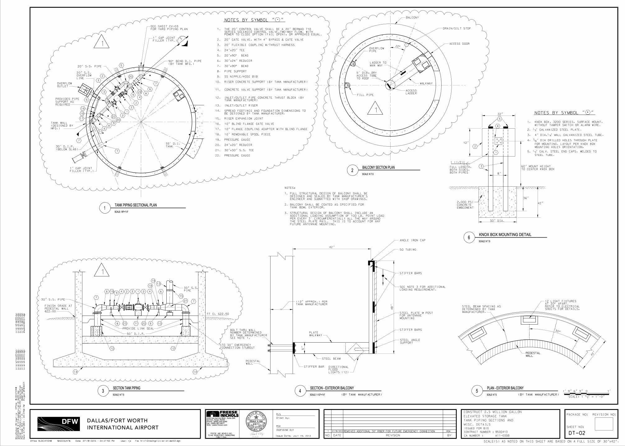
• Knox Box, DT-02 detail 6.
• Signage, DT-10.
• Lightning Protection at the Pre-Cast Communication Building. Sheet E-00, General Notes, Lightning Protection.
7. Bid Package #01 – Elevated Water Tank, Bid Forms item 14 is revised; “Provide all raceways cable tray and grounding to the vault and to 5’ outside of the Water Tower for all of the Instrumentation and Controls, Fire Alarm, Security and Fiber Optic Cabling work.”
8. Bid Package #02 – General Trades, Bid Forms item 8 is clarified as follows; ”Provide all raceways, cable tray and grounding from 5’ outside of the Water Tower for all of the Instrumentation and Controls, Fire Alarm, Security and Fiber Optic Cabling work, Also include any new or reworked raceways in the Central Utilities Plant and Airport Energy Plaza.”
9. The Earthwork and Lime Stabilization work is clarified as follows, Bid Package #01 includes all Foundation preparation for the Water Tank and any haul-off required. Bid Package #02 includes all Flatwork preparation and Lime Stabilization at the Paving per DT-07, Haul-Off of all trench spoils will be to a location on DFW Airport.
10. The Fire Alarm System will be provided in Bid Package #02 in accordance with Specification 16720.
Page 1 of 11
16 July 2013
DFW Airport – Elevated Water Tower
Bidder’s Questions – Addendum 03
1. The 24 SM fiber from SCADA to Energy Plaza Com Room, do we terminate with FJ? DFW’s standard is now duplex LC fusion spliced pigtail connectors. Please terminate
with LC in lieu of FJ. 2. Is the EC responsible to provide and install all of the specified inner ducts including the
duct banks? Conduit is specified under Electrical, Innerduct specified under Communications. Division of labor is responsibility of GC. The Contractor is responsible for providing and installing the new innerducts in the duct banks as identified on the plans. It is recommended that the Communications Contractor install innerducts for the Communications systems scope, but the General Contractor should determine this answer.
TOH Additional Comment – See Addendum Three.
3. Who is to provide and install the CCTV cabinet in the EST Com Room? Shown on Comm Plans. The Contractor is responsible to provide and install the equipment cabinets. Division of labor is responsibility of GC.
TOH Additional Comment – CCTV\Security is provided by Siemens and is not part of these Bid Packages.
4. Where is the fire panel, requiring the 2 strand fiber, located in the EST Comm Room? Location to be determined by Fire Alarm System Designer Contractor. Suggested location is near door, on West or North wall where space is available.
5. Who provides the SM patch cords? The Contractor shall provide the patch cables. 6. If the Communications contractor, is there a quantity with footages for the SM fiber
patch cords required for this project? Provide 1 duplex fiber patch cable for every two (2) strands of new fiber installed. Exact
patch cable quantities and lengths must be confirmed with Owner prior to actual purchase, however plan for ½ of cables @ 2m and ½ of cables @ 5m, unless noted otherwise on drawings.
7. Who is to provide the SCADA Server Rm keyboard console?
Page 2 of 11
The Contractor is responsible for providing the KVM console. 8. Page 16710-16, E, 1. States “Provide two vertical power strips for each equipment
cabinet.” Page 16710-22, 3.1, B. states “All NEW cabinets shall be installed with stabilization kits, quad fan kit (top), filtered ventilation system (bottom), thermal sensor, four flush mount power strips, four vertical cable managers, and horizontal front and rear cable management brackets above and below any copper patch panel provided. So the question is 2 or 4 power stripes per cabinet?
Two vertical power strips shall be provided for each cabinet.
9. This spec section lists Emtelle as an approved airblown fiber manufacturer. Would
Sumitomo Airblown Fiber be an acceptable alternative?
Sumitomo airblown fiber is not an approved alternative for the Outside Plant installations in this project.
10. FJ type connectors are no longer offered by Panduit. Would SC fiber pigtails be acceptable for termination of airblown fiber? In lieu of FJ connectors, provide duplex LC fusion spliced pigtail connectors.
11. Drawing DT-02 Detail 4 – Section – Exterior Balcony - Note 2 Balcony shall be coated as specified for tank bowl exterior. Recommend exterior balcony be hot dipped galvanized in accordance with pedestal ladders and landings.
The 3D rendering prepared for the Airport shows the same coating as the tank exterior. In addition to review of maintenance, operational and structural issues, a new rendering would need to be prepared for review by the Airport if a hot dip galvanized alternative is submitted. 12. Drawing DT-01 Detail 1 – Elevation Section References a Tideflex Mixing System or
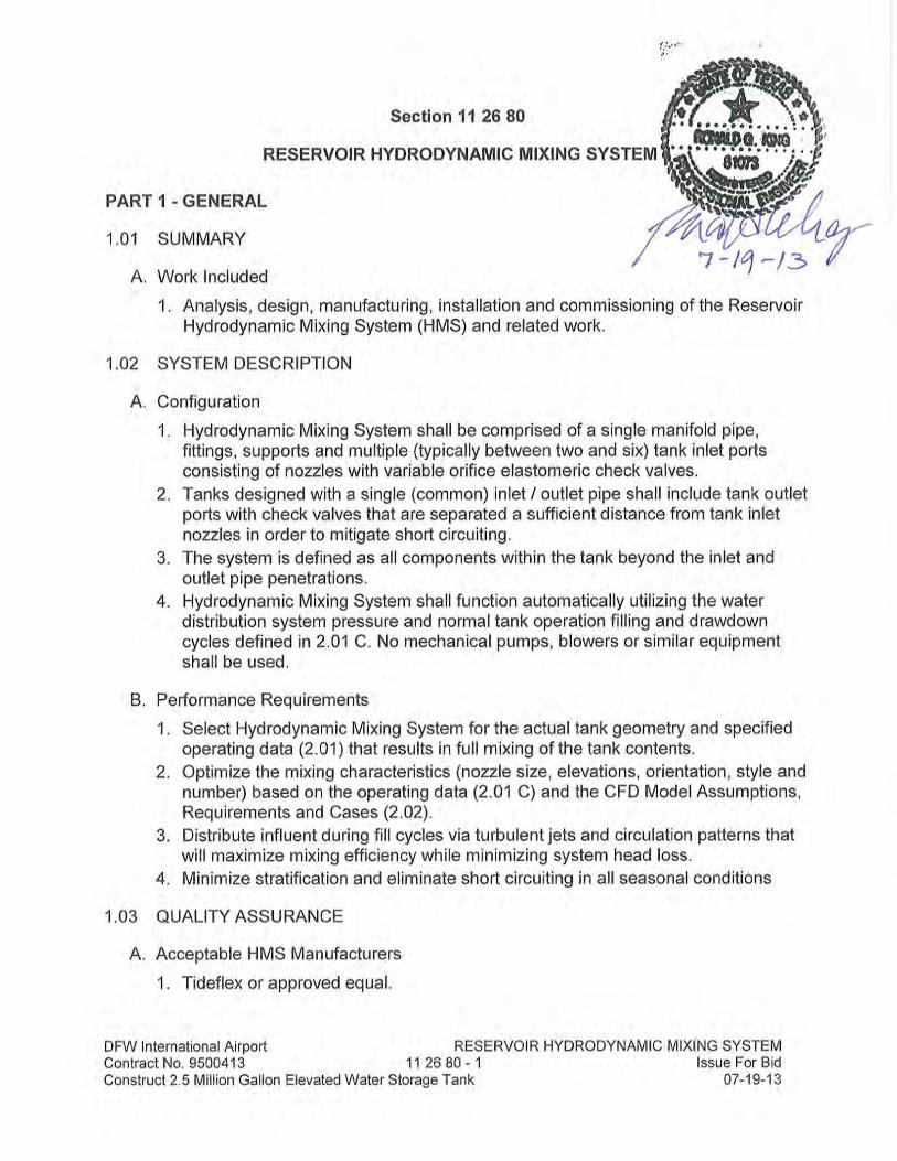
approved equal. No other guidance is provided in the specification. Recommend the attached specification verbiage to provide guidance for the analysis, design manufacturing, installation and commissioning of the tank mixing system.
Recommendation is accepted, see attached specification. 13. Section 09905 – Protective Coatings The proposed tank site is very close to adjacent
property. Recommend the following additional verbiage be added to the specification to protect adjacent property. “The Tank Contractor shall be fully responsible for protection of the adjacent property owners against blasting and painting operations and ensuring compliance with the applicable TCEQ requirements.”
Page 3 of 11
The referenced specification, Section 1.01 D does require containment of these materials.
14. Section 13413-4 – Section 1.04 Submittals - Item A. Proposal Calls for tank
manufacture to have a minimum ten years experience in construction of composite elevated tanks, and submit a list of a minimum of five composite elevated tanks of equal or greater capacity in successful operation for at least five years.Recommend ten (10) composite elevated tanks of equal or greater capacity in successful operation for at least five years per page 3A-10 Proposal Submittal Item #2 of the specification.
The intent is to receive Bid Package #01 pricing from qualified bidders, we are trying to provide the best value to DFW Airport and we will look closely at the qualifications and experience of the proposer. 15. Section 9 Subcontractor Pre-Qualification Information – what is the deadline to submit
this information?
There is no pre-bid deadline to submit Subcontractor prequalification. As previously stated in Addendum One We encourage all submitting subcontractors to visit and register on the Turner Construction Company prequalification website http://www.turnerconstruction.com/sub-contractors to expedite the contract award.
16. Are we required to provide Performance and Payment bonds? If so, what percentage? Payment and Performance Bonds may be required for the full amount of the Bid. 17. Following Section 00002F – Consultant Seal – Communications and before Division 1
General Requirements there is a three (3) page, 15 Item Bid Form. Do we submit this Bid Form as part of our submission? Is this to be used as the Bid Breakdown as mentioned on page 4 of the Bid Forms?
The 30 page document titled “Bid Forms” is the correct format. Do not use the bid form from the Project Manual.
18. Sheet CV-03 – please clarify if the following items are existing: - the 45 deg bend at STA 59+82.01 Existing - the 6” gate valve and hydrant at STA 59+85.30 Existing - the 78” RCP manhole Existing
19. Sheet DT-01, the pedestal diameter is shown as 55 ft. Our standard pedestal diameter for a 2.5 MG tank is 54 ft center to center. Please confirm the pedestal diameter can vary slightly to suit individual tank manufacturers’ standards.
Page 4 of 11
A 54 ft center of wall to center of wall diameter is acceptable. However, Contractor shall be required to provide a revised layout for review, during the tank shop drawings submittal phase, to ensure all equipment, piping, site elements, etc. are provided for appropriately. Other differing wall diameters would need to be submitted for approval in a similar manner.
20. Sheet DT-01 shows a tank diameter of 104 ft. While this may close to our final design we will surely vary slightly. Please confirm the final tank diameter is to be determined by the tank manufacturer.
See Note 1 on Sheet DT-01. It is understood some adjustment to the diameter may be needed to provide the required capacity.
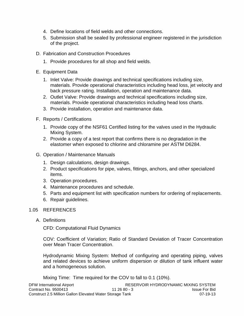
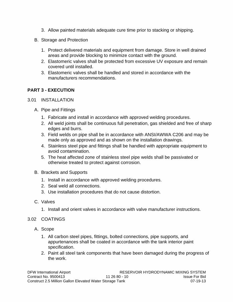
21. Sheet DT-02 – the tank piping section does not correspond with the plan view. Please confirm there is only (1) 30” riser.
The intent is for there to be one 30” riser. Sheet DT-02 has been revised accordingly and is attached.
22. Sheet DT-01 – can the mechanical layout/configuration be rearranged and altered slightly to make a more workable solution so as long as the intent of the proposed layout it met? I.E.: - 30” inlet/outlet - 20” overflow - 10” cross connect between the riser and the overflow - 20” altitude valve with valves for isolation - 20” by pass piping
Some adjustment may be acceptable. If adjustments are proposed, the Contractor will need to submit shop drawings of the desired adjustments during the tank shop drawing submittal phase for review.
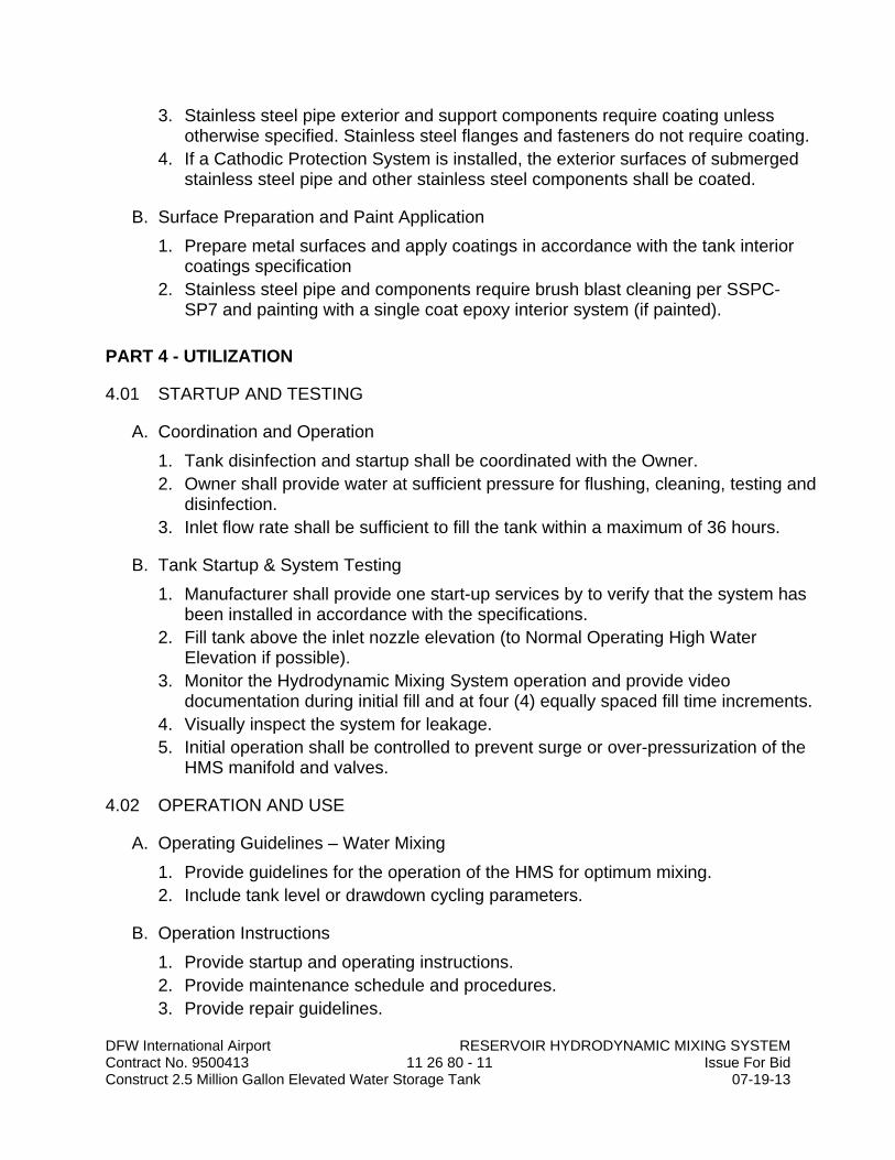
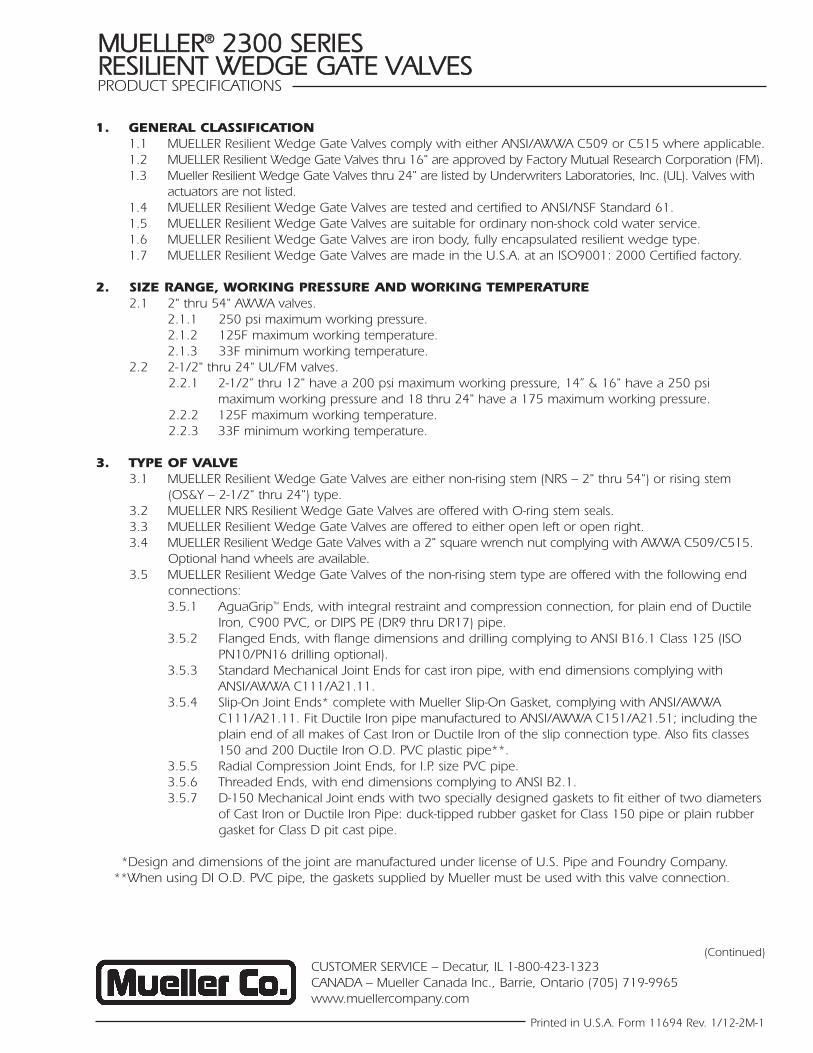
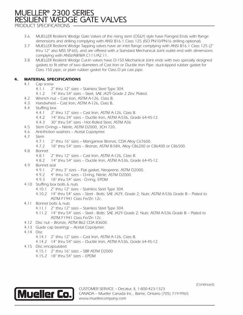
23. The data sheets from Mueller show the bypass size for a 20” gate valve as 2”, a 4” bypass is not available. Please confirm this is acceptable.
Page 5 of 11
The attached data sheet from Mueller appears to indicate that they use a bypass size that complies with AWWA C500. Table 11 of AWWA C500-09 indicates a 3” bypass valve is used for a 20” gate valve. Please provide additional confirmation from the valve manufacturer on this. It is appropriate for the bypass valve size to comply with this AWWA standard.
24. Sheet DT-01 Elevation View and Sheet DT-02 Balcony Plan show the access tube extending down to the upper platform. This is another manufacturers standard. Our standard construction detail does not permit the access tube to be taken past the tank floor. Either manufacturer’s standard will provide ladder access from the upper platform to the tank roof. Please confirm that individual manufacturer’s standard details will be acceptable.
It is acceptable to not extend the tube past the tank floor all the way down to the upper platform, as long as the appropriate ladder is provided, adequate fall prevention is provided, appropriate handrails are provided for the platform, and the ladder is not used for connection of lights, cables, etc.
25. Section 01810 includes a 7 part Commissioning Plan for the Elevated Tank prepared by Campos Engineering, the Commissioning Consultant. Please confirm any costs associated with Campos Engineering is by the Owner.
The costs associated with Campos Engineering are by DFW Airport, coordination and Commissioning Assistance is by the Contractors.
26. Sheet CV-03 – We recommend the tank location be moved slightly southerly as there is a conflict between the tank foundation (not shown) and the meter vault. There appears to be room to move south and still have a suitable maintenance easement.
This will depend upon the final foundation design that is provided by the selected tank manufacturer, and specific review of this request cannot be provided until the tank manufacturer is selected and the tank manufacturer provides the detailed dimensions and design of the foundation. Please note that any adjustment to the tank location will require formal FAA approval, since the FAA permit is based upon specific location of the tank. The Contractor will need to consider this with all adjustment requests.
Page 6 of 11
27. The specifications call for a maximum head range on the tank of 40’. For a 2,500,000 gallon tank our standard head range is 45’. There is significant cost associated with reducing the maximum head range from our standard. Is a 45’ head range acceptable?
A head range of 45 ft is acceptable, as long as the overflow elevation remains the same, and as long as the required capacity is provided between the overflow elevation and the tideflex outlet elevation as indicated on Sheet DT-01.
28. The geotech report indicates that the foundation should be a “mat” style or on caissons. Please verify that an annular ring foundation is acceptable.
Provide more information as to what is meant by an “annular ring foundation” (Ring cap on drilled piers? Ring wall down to and into rock? Shallow ring wall?). Regardless of which type is meant, note the requirements of Spec 13413 1.03.C concerning tank manufacturer’s responsibility for full foundation design, determination of adequacy of the geotechnical report, and obtaining any additional soils information and foundation data needed.
TOH Additional Comment – Please note Bid Package #01, Inclusion 4 regarding Professional Liability Insurance Limit required.
29. Please clarify how many rest platforms are required? There is conflicting information between the plans and specifications. Two (2) or Three (3) seems like a reasonable number for this tank geometry.
See Spec 13413 2.06 C.5 for required rest platform intervals.
30. The proposed communications building is very close to the tank and would restrict access during construction. When is the communications building scheduled to be installed?
The preliminary schedule is included in section 8 of the “Request for Bids” document. We have not specifically scheduled the installation of the Precast Concrete Building and will work with the selected contractors to determine the best method and time for all of the work.
Page 7 of 11
31. The cathodic protection system specifies cast-iron anodes which are not NSF approved. A better, less expensive , and NSF approved system utilizes Titanium anodes in a horizontal design position. Please verify that the alternate system is acceptable. (see attached)
In accordance with specification paragraph 3.04.A – B an alternate design may be bid. The design (calculations, installation details, anode configuration, materials catalogue sheets, and rectifier rating) must be submitted to the Engineer for approval prior to construction of the system.
32. Is a dome or flat roof desired for the tank?
Roof slope shall comply with TCEQ requirements and Spec 13413 2.05 C. In addition, the attached 3D rendering will assist with the visual aspects desired by the Airport. And finally, the roof elevations will need to provide for compliance with the maximum elevations of the roof and appurtenances on the roof indicated in the FAA permit (available from DFW Airport).
33. Please confirm AWWA D-107 and Section 13413 govern for the concrete support wall construction relating to mixes, curing, form removal, placement, slump, etc and Sections 03100, 03200, 03300 are secondary.
Spec 13413 governs for the concrete support wall.
34. Section 01400 Item 3.4.B identifies the requirement for the Contractor to have a full time QC employee dedicated to quality only. Please confirm this is a requirement of the Prime Contractor and the individual sub contractors such as a Tank Manufacturer are not required to have a stand alone QC Supervisor.
Turner Omega Howard will provide the full time Quality Control employee. All Contractors and Subcontractors must have a designated individual on site responsible for Quality Control. This Person may also be a Superintendent or Foreman.
35. The drawings (CV-03, DT-02) indicate the incoming waterline passing over the foundation, entering through the pedestal wall. This would require the foundation to be
Page 8 of 11
placed deeper than necessary that our design requires. Can the incoming waterline pass under our through the foundation or are we required to place the foundation deeper to allow the water main to pass over the foundation?
Straight pipe upstream and downstream of the proposed meter is required for proper operation of the meter, so any adjustment in pipe elevation would need to take this into consideration. The elevation of the piping immediately north of the meter vault is existing and set, so the amount of adjustment that can be made is limited. In general, it is acceptable to go under or through the foundation as long as the above parameters are considered, and as long as the tank manufacturer’s structural engineer has provided for it in his foundation design. Specific adjustment allowances would be reviewed when the tank manufacturer provides details of the foundation.
36. Project Safety Plan – Page 65 – does not permit portable metal ladders, with the only exception is for metal ladders designed and used specifically during steel erection. Portable and temporarily fixed metal ladders are an integral element of a unique construction process required in constructing an elevated tank. We assume our standard construction procedures would fall under TOH’s exception policy. Please confirm. From the specification: Metal Portable Ladders - A Hazard On Construction Work Portable aluminum and other lightweight metal ladders are used in industry and by the population at large. They create safety problems not associated with wood ladders. There are so many safety factors involved that it is our considered opinion that portable metal ladders shall not be used on Turner/Omega/Howard projects. The only exception to this policy is metal ladders designed and used specifically for attachment to scaffolds or steel skeletons during steel erection.
“Ladders Last” Policy: Ladders must be considered as a last means of access and egress for all work, and only be used where no other means is possible, with preference given to safer means of access. Safer means may include, but not be limited to: stairs, rolling stairs, scissor and aerial lifts, scaffolds and Tele-towers. Additionally, it may be possible to plan and sequence work in a way that minimizes the number of times that a worker has to leave the floor working level via ladder or other means to access other elevations, which often raises the frequency and severity of risk exposure.
NOTE: If the TOH safety department determines that the ONLY way to access your work area will be through a ladder, than a ladder-use permit will be issued by TOH safety personal.
Page 9 of 11
37. Project Safety Plan – Page 68 – The use of a bosuns chair is prohibited unless approved by the Business Unit Safety Director. Due to the nature of work and the contour of the tank the use of a bosuns chair is a requirement in constructing an elevated tank. Please confirm the use of a bosun’s chair will be approved by the BUSD.
From the specification: L) The use of a “bosuns” chair is prohibited unless approved by the Business Unit Safety Director.
A bosuns chair will ONLY be approved by the BUSD, if it is determined that there is no other means of access to work area. The use of aerial lifts will be recommended in lieu of bosuns chair.
38. Paint related questions: Please clarify that shop blasting and priming is allowed on both the interior and exterior surfaces of the steel portion of the tank. Shop applied primer to paint manufacture recommended mill thickness is normal for our methods.
This is allowable, but the steel would need to be re-blasted and re-primed on site after ground level tank shell welding is completed.
Please clarify paint inspection responsibility. There appears to be conflicts in Spec Page 09905-2 - 1.02.D.1 and 1.02.D.2. Is the Contractor responsible for the cost of any Owner or third party inspection?
The Contractor is required to establish and implement quality control procedures to ensure the coatings are applied as specified, which should include any testing needed to implement this quality control. The Contractor will be responsible for the cost of establishing and implementing the Contractor’s quality control procedures. In addition, the Owner will also have a third party inspector, and the Owner will pay for the services of the Owner’s third party inspector. However, the Owner’s third party inspections do not relieve the Contractor of the Contractor’s full responsibility for quality control on the project and for performing the work in accordance with the plans and specifications.
The same section page 5 1.06.H.3 states "Surfaces exposed to direct sunlight shall be shaded by awnings or other protective devices while coatings are being applied". This is impractical to do this to the exterior of this large steel tank. Please clarify.
The Contractor should be able to accomplish this with the system required for containing overspray (per 1.01 D of same Spec), such as shrouding, etc. If the Contractor cannot accomplish this, then Contractor shall obtain and implement the coating manufacturer’s recommendations concerning coating application in direct sunlight.
Page 10 of 11
How many logo(s) are required? Will a paper sheet (8.5 x 11) using color ink be acceptable as a paint & artwork mock-up regarding the logo and color combinations?
Two logos are required per Plan Sheet CV-01. However, during the mock-up review phase, the Owner may also desire adjustment to the number and/or orientations of the logos. Please plan on this review process to occur. A paper sheet for the mock-up is acceptable, but a jpeg or pdf should also be provided. The mock-up should also show a rendering of the tank and the placement of the logos on the tank. It should also indicate the codes of the colors that are proposed.
39. The lighting protection specifications call out many details that are not shown on the drawings. Please advise on these details.
The Lightning Specification (13100) is a performance specification. It is anticipated that a Lightning Protection Contractor will design the system in accordance with referenced standards, and in conjunction with the tank manufacturer. System shall be submitted as shop drawing, including plan, layout and details.
40. Please consider changing section 13413 page 8, 2.04B to 0.5%. ACI and AWWA do not require 1% in ring beam.
The minimum 1% is required
41. Drawing DT-01 detail 2 shows the emergency connection pipe coming from the inlet/outlet riser and going below grade to the stub with a plug. Drawing DT-02 section 3 shows the emergency fill pipe as a riser. Are there two risers or one? Can you provide a better detail of the riser pipe locations?
See above answer to Question #21.
42. There appears to be some confusion regarding electrical scope required in the 01 Elevated Water Tank scope and scope by others regarding the controls, and panels. Please clarify.
Please see the answer below regarding low voltage and electrical scopes.
43. Is there a value identified for LD's on a per day basis should the schedule over run?
Page 11 of 11
The liquidated damages are $1,000 per day.
44. What is the established $ budget for bid scopes 01, 02, & 03?
This budget has not been published.
45. At the pre-bid meeting it was highlighted that the project will be subdivided into three parts, and that everything on, in, or within 5’ of the Water Tower itself would be handled by the water contractor, and the remainder handled by another prime contractor. The scope of work includes new controls for information from/to the water tower to be integrated with two remote pump stations (East & West) and the CUP DeltaV control system. In review of this scope (Section 13401 1.01, in particular item K.) indicates that the PCSI will complete this entire integration. With that, it would not seem logical or feasible to divide this PCSI scope of work across the two subdivisions of the overall project. Will the PCSI (Section 13401) fall under the “Bid Package #01 – Elevated Water Tank” or “Bid Package #2 - General Trades” portion of work?
Please reference Bid Package #01, item 26, this states; “Provide Instrumentation and Control System.” Please reference sheet I-04, this sheet shows the locations of controls work in the vault, elevated storage tank and communications building. Please see sheet I-01 Plan 2 which shows the controls work in the Central Utilities Plant.
The intent of the Bid Packages is that the complete Section 13401 Controls Systems are included in the Bid Package #01 – Elevated Water Tank.
All Instrumentation and Controls wiring is in Bid Package #01 – Elevated Water Tank.
All conduits between the vault and the tower are part of Bid Package #01.
All Conduits between the Tower and the Communication Building are with Bid Package #01 to 5’ outside the Tower and Bid Package #02 from 5’ outside the tower to 12” AFF inside the Communications Building and then the continuation is completed by Section 13401 Instrumentation and Controls.
DFW International Airport RESERVOIR HYDRODYNAMIC MIXING SYSTEM Contract No. 9500413 11 26 80 - 2 Issue For Bid Construct 2.5 Million Gallon Elevated Water Storage Tank 07-19-13
2. Other manufacturers may submit proposals only if they show conformance with the specification criteria and provide complete submittals in accordance with 1.04 Submittals.
B. HMS Manufacturer Experience Requirements
1. Five years experience in the design, manufacture and installation of Hydrodynamic Mixing Systems.
2. A minimum of ten Hydrodynamic Mixing System installations that comply with the requirements of this specification.
C. Professional Engineer
1. The Professional Engineer in responsible charge of the Hydrodynamic Mixing System shall have minimum five years related experience in design, manufacture, installation and operation.
1.04 SUBMITTALS
A. Hydrodynamic Mixing System Experience
1. Provide completed contracts summary - minimum ten Hydrodynamic Mixing Systems designed, manufactured and installed.
2. Show installation location, Owner contact with phone number and year completed.
B. Analysis & Design
1. Perform a CFD analysis of the mixing system, using actual tank geometry and parameters, and prepare a full design of the mixing system.
2. Provide a summary of the analysis and design for the proposed Hydrodynamic Mixing System.
3. Include tank geometry, operational data and CFD model parameters and assumptions.
4. Include calculated jet velocities, head loss for inlet flow (2.02 F), outlet flow (2.02 G) and analysis results (2.02 E).
5. Provide required deliverables for all modeling cases (2.02 D). 6. Provide required minimum drawdown resulting in full mixing during a fill cycle for
a range of operational flows.
C. Design Drawings
1. Provide elevation, plan, sectional view and detail drawings of the installed Hydrodynamic Mixing System as well as all appurtenant equipment, attachments and accessories.
2. Show location, orientation, dimensions, sizing and materials of construction for piping, inlet and outlet ports, valves and equipment.
3. Show the material specification and finish requirements.
DFW International Airport RESERVOIR HYDRODYNAMIC MIXING SYSTEM Contract No. 9500413 11 26 80 - 3 Issue For Bid Construct 2.5 Million Gallon Elevated Water Storage Tank 07-19-13
4. Define locations of field welds and other connections. 5. Submission shall be sealed by professional engineer registered in the jurisdiction
of the project.
D. Fabrication and Construction Procedures
1. Provide procedures for all shop and field welds.
E. Equipment Data
1. Inlet Valve: Provide drawings and technical specifications including size, materials. Provide operational characteristics including head loss, jet velocity and back pressure rating. Installation, operation and maintenance data.
2. Outlet Valve: Provide drawings and technical specifications including size, materials. Provide operational characteristics including head loss charts.
3. Provide installation, operation and maintenance data.
F. Reports / Certifications
1. Provide copy of the NSF61 Certified listing for the valves used in the Hydraulic Mixing System.
2. Provide a copy of a test report that confirms there is no degradation in the elastomer when exposed to chlorine and chloramine per ASTM D6284.
G. Operation / Maintenance Manuals
1. Design calculations, design drawings. 2. Product specifications for pipe, valves, fittings, anchors, and other specialized
items. 3. Operation procedures. 4. Maintenance procedures and schedule. 5. Parts and equipment list with specification numbers for ordering of replacements. 6. Repair guidelines.
1.05 REFERENCES
A. Definitions
CFD: Computational Fluid Dynamics COV: Coefficient of Variation; Ratio of Standard Deviation of Tracer Concentration
over Mean Tracer Concentration. Hydrodynamic Mixing System: Method of configuring and operating piping, valves
and related devices to achieve uniform dispersion or dilution of tank influent water and a homogeneous solution.
Mixing Time: Time required for the COV to fall to 0.1 (10%).
DFW International Airport RESERVOIR HYDRODYNAMIC MIXING SYSTEM Contract No. 9500413 11 26 80 - 4 Issue For Bid Construct 2.5 Million Gallon Elevated Water Storage Tank 07-19-13
Negative buoyancy: condition when incoming water is cooler than the tank contents. Neutral buoyancy: condition when incoming water has the same temperatures as the
tank contents. Thermal Stratification: Layered variations of density and temperature in the stored
water volume.
B. Reference Standards
The latest version of the following Specifications, Codes and Standards are referenced in this section.
1. American Institute of Steel Construction (AISC)
S360-10 Specification for Structural Steel Buildings
2. American Society of Mechanical Engineers (ASME) B16.5 Pipe Flanges and Flanged Fittings
B36.10 Welded and Seamless Wrought Steel Pipe
3. American Society for Testing Materials (ASTM) A 123 Zinc Coatings on Iron and Steel Products
A 240 Stainless Steel Plate, Sheet and Strip for Pressure Vessels
A 285 Pressure Vessel Plates, Carbon Steel
A 774 Welded Stainless Steel Fittings
A 778 Welded Stainless Steel Tubular Products
4. American Water Works Association (AWWA) D102 Coating Steel Water Storage Tanks
C200 Steel Water Pipe - 6 inch (150 mm) and Larger.
C206 Field Welding of Steel Water Pipe.
C207 Steel Pipe Flanges for Waterworks Service, 4 inch through 144 inch
C220 Stainless Steel Pipe
C652 Disinfection of Water Storage Facilities
5. American Welding Society (AWS) D 1.1 Structural Welding Code – Steel
D 1.6 Structural Welding Code – Stainless Steel
D 10.4 Recommended Practice for Welding Stainless Steel Pipe & Tubing
6. ASTM International (ASTM): A53 Specification for Pipe, Steel, Black and Hot Dipped, Zinc Coated,
Welded and Seamless
D6284 Standard Test Method for Rubber Property—Effect of Aqueous Solutions with Available Chlorine and Chloramine
DFW International Airport RESERVOIR HYDRODYNAMIC MIXING SYSTEM Contract No. 9500413 11 26 80 - 5 Issue For Bid Construct 2.5 Million Gallon Elevated Water Storage Tank 07-19-13
7. National Sanitation Foundation (NSF) 61 Standard for Drinking Water System Components
8. Steel Structures Painting Council (SSPC) VIS-89 Visual Standard for Abrasive Blast Cleaned Steel
PART 2 - PRODUCTS
2.01 WATER STORAGE TANK DATA
A. Water Tank Structure Data
1. Tank Style – Composite Elevated Tank 2. Tank Support – Single Concrete Pedestal 3. Central Riser – No 4. Tank Volume (gallons) – 2,500,000 5. Tank Dimensions (feet) – 104’ diameter x 40’ or 45’ HR (Note: final dimensions
of tank will be determined by tank manufacturer, and analysis/design of mixing system shall use the final dimensions.)
6. Overflow Elevation – 780.00 7. Ground Elevation – 622.00
B. Mechanical Data
1. Inlet Pipe Diameter (inches) – 30 2. Common Inlet / Outlet Pipe – Yes 3. Outlet Pipe Diameter (inches) – 30
C. Operating Data
1. Normal Operating High Water Elevation – 779.00 2. Normal Operating Low Water Elevation – Will be provided by Owner’s Engineer
at time of analysis 3. Normal Operating Range (feet) – Will be provided by Owner’s Engineer at time of
analysis 4. Duration of Fill Periods (hours per day) – Will be provided by Owner’s Engineer
at time of analysis 5. Average Fill Flow Rate during Fill Periods (gpm) – Will be provided by Owner’s
Engineer at time of analysis 6. Minimum Fill Flow Rate (gpm) – Will be provided by Owner’s Engineer at time of
analysis 7. Maximum Fill Flow Rate (gpm) – Will be provided by Owner’s Engineer at time of
analysis 8. Normal Maximum Outlet Flow Rate (gpm) – Will be provided by Owner’s
Engineer at time of analysis
DFW International Airport RESERVOIR HYDRODYNAMIC MIXING SYSTEM Contract No. 9500413 11 26 80 - 6 Issue For Bid Construct 2.5 Million Gallon Elevated Water Storage Tank 07-19-13
9. Emergency Maximum Outlet Flow Rate (gpm) – Will be provided by Owner’s Engineer at time of analysis
D. Other Data
1. Cathodic Protection System installed in tank – Yes 2. Pressure Transducer provided to control tank elevation - Yes
2.02 ANALYSIS AND DESIGN
A. General Analytical Requirements
1. The following analysis and design specifications are minimum requirements. 2. The proposed Hydrodynamic Mixing System design shall be based on an
analysis that is specific to the tank geometry, operational data, assumptions and cases under consideration. An analysis based on generic conditions will not be accepted.
3. The CFD model shall be capable of simulating the physical behavior of water mixing in the tank during operation.
4. CFD software shall be capable of analyzing both steady state and transient flow of fluid. Acceptable commercial software packages are CFX Ansys, Fluent or equal.
5. Analysis shall be performed by a skilled analyst having experience in simulating water flow patterns within tanks.
B. CFD Model Requirements
1. Geometry of the tank structure and Hydrodynamic Mixing System piping used for the model shall be within 20% of actual.
2. Mesh definition shall be selected by a skilled analyst. Zones adjacent to inlet and outlet ports and along the inlet jet path shall be modeled with significantly higher concentration of nodes than regions of relatively low velocity.
3. The model shall simulate simultaneous filling and drawing of the tank at Normal Operating High Water Elevation (2.01 C.1) as an acceptable approximation of varying water elevation during intermittent fill – draw cycles. Analysis shall be run until COV reaches 5%.
C. CFD Model Assumptions
1. The primary modeling method to evaluate water mixing and circulation requires a neutrally buoyant tracer. The tracer shall be injected into the inlet water jet at the beginning of the fill cycle. The tracer concentration shall be 1.0 and the tank contents initial concentration shall be 0.0.
2. Coefficient of Variation (COV) shall be used to define mixing time. COV = Ratio of Standard Deviation of Tracer Concentration over Mean Tracer Concentration. Mixing Time is the time required for the COV to fall to 0.1 (10%).
DFW International Airport RESERVOIR HYDRODYNAMIC MIXING SYSTEM Contract No. 9500413 11 26 80 - 7 Issue For Bid Construct 2.5 Million Gallon Elevated Water Storage Tank 07-19-13
3. CFD simulation shall utilize steady state model for determination of the steady velocity field.
4. CFD simulation shall utilize full transient model for determination of mixing time. 5. The k-epsilon turbulence model shall be used unless a more sophisticated
approach is required.
D. CFD Modeling Cases
1. Case 1: Average Fill Flow Rate (2.01 C.5), Normal Operating High Water Elevation (2.01 C.1), Neutral buoyancy condition = inlet water same as temperature of tank contents.
2. Case 2: Average Fill Flow Rate (2.01 C.5), Normal Operating High Water Elevation (2.01 C.1), Negative buoyancy condition = inlet water 10ºF less than temperature of tank contents.
3. Tank contents shall be at uniform temperature prior to fill cycle. 4. Case 2 provides a relative measure of the effectiveness of the Hydrodynamic
Mixing System for lower inlet temperature conditions. Compare with Case 1.
E. CFD Modeling Output (Governing Case)
1. Mixing Time. 2. Graphic diagrams: Tracer distribution, streamlines, and diagrams showing
change of tracer concentration with time.
F. Inlet Design
1. Based on CFD analysis results calculate velocities and head loss at the inlet valves for Minimum, Average and Maximum Fill Flow Rate (2.01 C.5, C.6 and C.7).
2. Consider Hydrodynamic Mixing System components and piping within tank only in head loss calculations.
3. Unless otherwise specified, minimum HMS manifold diameter shall be the same as the tank inlet pipe.
4. Provide vacuum relief port at the top of the inlet manifold. 5. Maximum 2.0 ft. head loss during Average Fill Flow Rate (2.01 C.5), unless
otherwise specified. 6. Maximum 4.0 ft. head loss during Maximum Fill Flow Rate (2.01 C.7), unless
otherwise specified.
G. Outlet Design
1. Maximum 2.0 ft. head loss during Normal Maximum Outlet Flow Rate (2.01 C.8), unless otherwise specified.
2. Maximum 4.0 ft. head loss during Emergency Maximum Outlet Flow Rate (2.01 C.9), unless otherwise specified.
DFW International Airport RESERVOIR HYDRODYNAMIC MIXING SYSTEM Contract No. 9500413 11 26 80 - 8 Issue For Bid Construct 2.5 Million Gallon Elevated Water Storage Tank 07-19-13
3. If outlet check valves are required to be installed within the tank, provide a minimum of two (2) for redundant operation.
H. Structural Design
1. Tank engineer of record shall review and approve attachment and support points between the HMS and the tank components.
2. Pipe supports and ancillary items shall comply with AISC. Structural analysis shall consider the effects under maximum flow conditions.
3. Tank modifications required to accommodate the Hydrodynamic Mixing System shall be fully analyzed and designed in accordance with the applicable structural design codes and standards.
2.03 MATERIALS AND COMPONENTS
A. Pipe and Fittings shall be stainless steel
1. Stainless steel pipe shall be Type 304L fabricated from ASTM A-240 materials. 2. Fabrication, inspection, testing, marking and certification of pipe and fittings shall
be in accordance with ASTM A-778 and ASTM A-774. 3. Flanges shall be Type 304L stainless steel. Flange design by Manufacturer with
bolt pattern per ANSI B16.5.
B. Flange Gaskets
1. Gaskets shall be 1/8” full-faced, in accordance with ASTM D1330. 2. Gasket material shall be Neoprene.
C. Fasteners
1. Hex head bolts and nuts shall conform to ANSI/ASME B18.2.1 and B18.2.2. 2. Provide Type 316L stainless steel. 3. Provide isolation sleeves and washers for connections with dissimilar metals.
D. Brackets, Clips & Supports
1. ASTM A36 steel or equal. 2. Fabricate using flat bar or sealed tubular sections. Details that are difficult to
maintain or paint in the field will not be accepted. 3. Bracket or support material directly in contact with stainless steel pipe shall be
Type 304L stainless steel.
E. Tank Inlet Valves
1. Provide variable orifice elastomeric check valve that allows water to enter the tank during fill cycles while preventing reverse flow (into the outlet pipe) during draw periods.
DFW International Airport RESERVOIR HYDRODYNAMIC MIXING SYSTEM Contract No. 9500413 11 26 80 - 9 Issue For Bid Construct 2.5 Million Gallon Elevated Water Storage Tank 07-19-13
2. Valve manufacturer shall have minimum ten years experience in the manufacturing of variable orifice style elastomeric valves.
3. Valve manufacturer shall have conducted hydraulic testing to determine head loss, jet velocity and back pressure characteristics.
4. Elastomer shall be one-piece internally reinforced EPDM or approved equal. 5. Flange backing ring components shall be Type 304 stainless steel. 6. Valves shall be NSF Standard 61 certified. 7. The elastomer used in construction of valves shall be tested in accordance with
ASTM D6284 to confirm there is no degradation in the elastomer when exposed to chlorine and chloramine.
8. Onyx Duckbill Check Valve, Tideflex or approved equal.
F. Tank Outlet Valves (Single Inlet / Outlet Pipe Configuration)
1. Wafer style type elastomeric membrane that allows water to enter the outlet pipe during draw cycles while preventing reverse flow (into the tank) during fill periods.
2. Valve manufacturer shall have minimum ten years experience in the manufacturing of wafer style elastomeric valves.
3. Valve manufacturer shall have conducted hydraulic testing to determine head loss characteristics.
4. Elastomer shall be one-piece internally reinforced EPDM or approved equal. 5. Flange disc plate and other metal components shall be Type 304 stainless steel. 6. Valves shall be NSF Standard 61 certified. 7. The elastomer used in construction of valves shall be tested in accordance with
ASTM D6284 to confirm there is no degradation in the elastomer when exposed to chlorine and chloramine.
8. Onyx Wafer Check Valve, Tideflex or approved equal.
G. Coatings
1. In the absence of a tank interior paint specification, coatings shall comply with the following, or equal:
(1st coat) Tnemec Series 20 4-6 mils dry film thickness (2nd coat) Tnemec Series 20 4-6 mils dry film thickness 2. Products listed are intended to establish a standard of quality. All paint used on
surfaces which are to be in contact with potable water shall be compatible with existing systems and shall be certified by NSF.
2.04 DELIVERY, STORAGE AND HANDLING
A. Handling and Shipping
1. Handle materials and fabricated components in a manner that will protect them from damage.
2. Stainless steel components shall be separated carbon steel components or other materials that could damage the stainless steel finish.
DFW International Airport RESERVOIR HYDRODYNAMIC MIXING SYSTEM Contract No. 9500413 11 26 80 - 10 Issue For Bid Construct 2.5 Million Gallon Elevated Water Storage Tank 07-19-13
3. Allow painted materials adequate cure time prior to stacking or shipping.
B. Storage and Protection
1. Protect delivered materials and equipment from damage. Store in well drained areas and provide blocking to minimize contact with the ground.
2. Elastomeric valves shall be protected from excessive UV exposure and remain covered until installed.
3. Elastomeric valves shall be handled and stored in accordance with the manufacturers recommendations.
PART 3 - EXECUTION
3.01 INSTALLATION
A. Pipe and Fittings
1. Fabricate and install in accordance with approved welding procedures. 2. All weld joints shall be continuous full penetration, gas shielded and free of sharp
edges and burrs. 3. Field welds on pipe shall be in accordance with ANSI/AWWA C206 and may be
made only as approved and as shown on the installation drawings. 4. Stainless steel pipe and fittings shall be handled with appropriate equipment to
avoid contamination. 5. The heat affected zone of stainless steel pipe welds shall be passivated or
otherwise treated to protect against corrosion.
B. Brackets and Supports
1. Install in accordance with approved welding procedures. 2. Seal weld all connections. 3. Use installation procedures that do not cause distortion.
C. Valves
1. Install and orient valves in accordance with valve manufacturer instructions.
3.02 COATINGS
A. Scope
1. All carbon steel pipes, fittings, bolted connections, pipe supports, and appurtenances shall be coated in accordance with the tank interior paint specification.
2. Paint all steel tank components that have been damaged during the progress of the work.
DFW International Airport RESERVOIR HYDRODYNAMIC MIXING SYSTEM Contract No. 9500413 11 26 80 - 11 Issue For Bid Construct 2.5 Million Gallon Elevated Water Storage Tank 07-19-13
3. Stainless steel pipe exterior and support components require coating unless otherwise specified. Stainless steel flanges and fasteners do not require coating.
4. If a Cathodic Protection System is installed, the exterior surfaces of submerged stainless steel pipe and other stainless steel components shall be coated.
B. Surface Preparation and Paint Application
1. Prepare metal surfaces and apply coatings in accordance with the tank interior coatings specification
2. Stainless steel pipe and components require brush blast cleaning per SSPC- SP7 and painting with a single coat epoxy interior system (if painted).
PART 4 - UTILIZATION
4.01 STARTUP AND TESTING
A. Coordination and Operation
1. Tank disinfection and startup shall be coordinated with the Owner. 2. Owner shall provide water at sufficient pressure for flushing, cleaning, testing and
disinfection. 3. Inlet flow rate shall be sufficient to fill the tank within a maximum of 36 hours.
B. Tank Startup & System Testing
1. Manufacturer shall provide one start-up services by to verify that the system has been installed in accordance with the specifications.
2. Fill tank above the inlet nozzle elevation (to Normal Operating High Water Elevation if possible).
3. Monitor the Hydrodynamic Mixing System operation and provide video documentation during initial fill and at four (4) equally spaced fill time increments.
4. Visually inspect the system for leakage. 5. Initial operation shall be controlled to prevent surge or over-pressurization of the
HMS manifold and valves.
4.02 OPERATION AND USE
A. Operating Guidelines – Water Mixing
1. Provide guidelines for the operation of the HMS for optimum mixing. 2. Include tank level or drawdown cycling parameters.
B. Operation Instructions
1. Provide startup and operating instructions. 2. Provide maintenance schedule and procedures. 3. Provide repair guidelines.
DFW International Airport RESERVOIR HYDRODYNAMIC MIXING SYSTEM Contract No. 9500413 11 26 80 - 12 Issue For Bid Construct 2.5 Million Gallon Elevated Water Storage Tank 07-19-13
4.02 WARRANTY AND CORRECTION PERIOD
A. Warranty and Correction Period Inspection
1. All HMS components shall be warranted by the manufacturer against failure under design conditions for a period on two (2) years from the date of startup and operation.
2. Components include piping, pipe support brackets, valves, expansion joints, anchors and other equipment specified in this section.
3. Components damaged as a result of improper operation, maintenance activities, or foreign debris, are excluded.
B. Warranty Inspection and Corrections
1. Owner shall drain and inspect tank within the warranty period. 2. Manufacturer shall correct any damage covered by the warranty.
PART 5 – MEASUREMENT & PAYMENT Measurement and payment for Reservoir Hydrodynamic Mixing System (HMS) shall be subsidiary to the placement of the tank. Refer to specification section 13413 – Composite Elevated Tank for measurement and payment.
END OF SECTION
14 14
7
6 4 2 3 1 2 4 6
8 811
12
FINISH GRADE AT
PEDESTAL WALL
622.00
10
13
15
19
FF EL 622.50
9
8"
1
2
3
4
5
1 (1/2)
30" DIA.
36"
42"
22"
12"
60" MOUNT HEIGHT
TO CENTER KNOX BOX
2,000 PSI
CONCRETE
EMBEDMENT
FULL LENGTH,
BOTH SIDES,
BOTH PIPES
18
19
30" S.S.
PIPE
21
20 20
7
12
CL
REVISION NO:
Drawn by:
Approved by:
Issue Date: NO. DATE REVISION BY
SCALE(S) AS NOTED ON THIS SHEET ARE BASED ON A FULL SIZE OF 30"x42".
SHEET NO:
PACKAGE NO:
Date:
Plotter:
$A
CC
OU
NT$
07\
18\
2013 - 04:3
7:5
0
PM
J:\
Plotdrv_
XM\
PD
F_
File\
PD
F-
Mono-
Half.plt
rjs
cv-air-dt-det02.d
gn
cv-air-dt-det02.d
gn
cv-air-pl-tank01.d
gn
cv-air-dt-det02.d
gn
dfwsheet304
2r1.d
gn
N:\if\
Dra
win
gs\cv-air-dt-det02.d
gn
16:0 ’:" / in.
Plot Scale:
cv-air-pl-tank01.d
gn
cv-air-dt-det02.d
gn
cv-air-dt-det02.d
gn
cv-air-dt-det02.d
gn
cv-air-dt-det02.d
gn
Micro
Statio
n
V8
User:
Date: 07\18\2013 - 04:37:50 PM User: rjs File:$ACCOUNT$$LOCATION$Office:
$L
OC
ATIO
N$
Offic
e:
N:\if\Drawings\cv-air-dt-det02.dgn
Project:
DF
W0637
1
Default
Model:
RONALD G. KING
81073
D
ERETSI
GE
R
RE
ENI
GNELANOI
SS
E
FO
R
S
TATE O
S
AXETF
P
FREESE AND NICHOLS, INC.
TEXAS REGISTERED ENGINEERING
FIRM F-2144
CONTRACT NUMBER : 9500413
CA NUMBER : A11-035B
RJS
RGK
ISSUED FOR BID
2220 San Jacinto Blvd., Suite 330
# NOTES BY SYMBOL " "
DT-02
42"
48"
STEEL ANGLE
SUPPORT
PEDESTAL
WALL
PLATE
WALKWAY
PEDESTAL
WALL
6"
SQ TUBING
STIFFER BARS
STIFFER BARS
STEEL BEAM
STIFFER BAR
STEEL PLATE @ POST
FOR ANTENNAE
MOUNTING
1’ 0 1’3"6"9"
SCALE: 1 �" = 1’-0"
ACCESS DOOR
BALCONY
DRAIN/SILT STOP
WALKWAY
FILL PIPE
ANGLE IRON CAP
42"
BOLT THRU WALL
NUMBER DETERMINED
BY TANK MANUFACTURER
SEE NOTE 1.
12 LIGHT FIXTURES
AT 30^ APART.
REFER TO ELECTRICAL
SHEETS FOR DETAILS.
1
2
2
3
3
2
4
6
7
5
4
5
6
OVERFLOW
OUTLET
8
8
9
16
17
PROVIDES PIPE
SUPPORT AS
REQUIRED
1" GAP JOINT
FILLER (TYP.)
1" GAP JOINT
FILLER (TYP.)
3
90^ BEND D.I. PIPE
(BY TANK MFG.)
9
20" S.S. PIPE
20" S.S.
OVERFLOW
LINE
55’ D.I.
TANK
DIRECTIONAL
FLOOD
LIGHTS (12)
18
SEE SHEET CV-03
FOR YARD PIPING PLAN
(12" APPROX.) PER
TANK MANUFACTURER
(BY TANK MANUFACTURER)
SEE NOTE 3 FOR ADDITIONAL
LOADING REQUIREMENT.
STEEL BEAM SPACING AS
DETERMINED BY TANK
MANUFACTURER.
(BY TANK MANUFACTURER)
7. 30"x90^ BEND
8. PIPE SUPPORT
14. SPREAD FOOTINGS AND FOUNDATION DIMENSIONS TO
19. PRESSURE GAUGE
# NOTES BY SYMBOL " "
1. KNOX BOX, 3200 SERIES, SURFACE MOUNT,
WITHOUT TAMPER SWITCH OR ALARM WIRE.
2. �" GALVANIZED STEEL PLATE.
3. 4" DIA,�" WALL GALVANIZED STEEL TUBE.
4. �" DIA DRILLED HOLES THROUGH PLATE
MOUNTING HOLES ORIENTATION.
FOR MOUNTING. LAYOUT PER KNOX BOX
5. �" GALV. STEEL END CAPS, WELDED TO
STEEL TUBE.
5’ DIA. DRY
ACCESS TUBE
TO ROOF
ACCESS
LADDER
2. 20" GATE VALVE, WITH 4" BYPASS & GATE VALVE
NOTES:
1. FULL STRUCTURAL DESIGN OF BALCONY SHALL BE
DESIGNED AND SEALED BY TANK MANUFACTURER’S
ENGINEER AND SUBMITTED WITH SHOP DRAWINGS.
2. BALCONY SHALL BE COATED AS SPECIFIED FOR
TANK BOWL EXTERIOR.
3. STRUCTURAL DESIGN OF BALCONY SHALL INCLUDE AN
ADDITIONAL LOADING ASSUMPTION OF 100 LB. POINT LOAD
PER EVERY 3’ CIRCUMFERENTIALLY ALL THE WAY AROUND
THE STEEL PLATE RAIL. THIS IS TO ACCOUNT FOR ANY
FUTURE ANTENNAE MOUNTING.
1. THE 20" CONTROL VALVE SHALL BE A 20" BERMAD 710
3. 20" FLEXIBLE COUPLING W/THRUST HARNESS
4. 24"x20" TEE
5. 20"x90^ BEND
6. 30"x24" REDUCER
10. RISER CONCRETE SUPPORT (BY TANK MANUFACTURER)
9. SS NIPPLE/HOSE BIB
11. CONCRETE VALVE SUPPORT (BY TANK MANUFACTURER)
12. INLET/OUTLET PIPE CONCRETE THRUST BLOCK (BY
TANK MANUFACTURER)
13. INLET/OUTLET RISER
BE DESIGNED BY TANK MANUFACTURER.
15. RISER EXPANSION JOINT
16. 10" BLIND FLANGE GATE VALVE
17. 10" FLANGE COUPLING ADAPTER WITH BLIND FLANGE
18. 10" REMOVABLE SPOOL PIECE
30" D.I.P.
30" S.S. PIPE
POWER T0 CLOSE OPTION (FAIL OPEN), OR APPROVED EQUAL.
SERIES SOLENOID CONTROL VALVE,TWO-WAY FLOW, WITH
SCALE: 1/8"=1’-0"
1
TANK PIPING SECTIONAL PLAN
SCALE: N.T.S.
2
BALCONY SECTION PLAN
SCALE: N.T.S.
6
KNOX BOX MOUNTING DETAIL
SCALE: N.T.S.
5
PLAN - EXTERIOR BALCONY
SCALE: 1-1/2"=1’-0"
4
SECTION - EXTERIOR BALCONY
SCALE: N.T.S.
3
SECTION TANK PIPING
LADDER TO
MAN WAY
OVERFLOW
PIPE
PROVIDE LINK SEAL
20
22
22
20
21
7
7
TANK WALL
(DESIGNED BY
MFG.)
30" D.I.P.
(BELOW SLAB)
20. 24"x20" REDUCER
21. 30"x30" S.S. TEE
22. PRESSURE GAUGE
CONSTRUCT 2.5 MILLION GALLON
ELEVATED STORAGE TANK
TANK PIPING SECTIONS AND
MISC. DETAILS
1
1
1
07/16/2013 REMOVED ADDITIONAL 30" RISER FOR FUTURE EMERGENCY CONNECTION RGK1
TO 30" EMERGENCY
CONNECTION STUBOUT
JULY 19, 2013
MMUUEELLLLEERR®® 22330000 SSEERRIIEESSRREESSIILLIIEENNTT WWEEDDGGEE GGAATTEE VVAALLVVEESSPRODUCT SPECIFICATIONS
CUSTOMER SERVICE – Decatur, IL 1-800-423-1323CANADA – Mueller Canada Inc., Barrie, Ontario (705) 719-9965www.muellercompany.com
Printed in U.S.A. Form 11694 Rev. 1/12-2M-1
1. GENERAL CLASSIFICATION1.1 MUELLER Resilient Wedge Gate Valves comply with either ANSI/AWWA C509 or C515 where applicable.1.2 MUELLER Resilient Wedge Gate Valves thru 16" are approved by Factory Mutual Research Corporation (FM).1.3 Mueller Resilient Wedge Gate Valves thru 24" are listed by Underwriters Laboratories, Inc. (UL). Valves with
actuators are not listed.1.4 MUELLER Resilient Wedge Gate Valves are tested and certified to ANSI/NSF Standard 61.1.5 MUELLER Resilient Wedge Gate Valves are suitable for ordinary non-shock cold water service.1.6 MUELLER Resilient Wedge Gate Valves are iron body, fully encapsulated resilient wedge type.1.7 MUELLER Resilient Wedge Gate Valves are made in the U.S.A. at an ISO9001: 2000 Certified factory.
2. SIZE RANGE, WORKING PRESSURE AND WORKING TEMPERATURE2.1 2" thru 54" AWWA valves.
2.1.1 250 psi maximum working pressure.2.1.2 125F maximum working temperature.2.1.3 33F minimum working temperature.
2.2 2-1/2" thru 24" UL/FM valves.2.2.1 2-1/2” thru 12" have a 200 psi maximum working pressure, 14” & 16" have a 250 psi
maximum working pressure and 18 thru 24" have a 175 maximum working pressure.2.2.2 125F maximum working temperature.2.2.3 33F minimum working temperature.
3. TYPE OF VALVE3.1 MUELLER Resilient Wedge Gate Valves are either non-rising stem (NRS – 2" thru 54") or rising stem
(OS&Y – 2-1/2" thru 24") type.3.2 MUELLER NRS Resilient Wedge Gate Valves are offered with O-ring stem seals.3.3 MUELLER Resilient Wedge Gate Valves are offered to either open left or open right.3.4 MUELLER Resilient Wedge Gate Valves with a 2" square wrench nut complying with AWWA C509/C515.
Optional hand wheels are available.3.5 MUELLER Resilient Wedge Gate Valves of the non-rising stem type are offered with the following end
connections:3.5.1 AguaGrip™ Ends, with integral restraint and compression connection, for plain end of Ductile
Iron, C900 PVC, or DIPS PE (DR9 thru DR17) pipe.3.5.2 Flanged Ends, with flange dimensions and drilling complying to ANSI B16.1 Class 125 (ISO
PN10/PN16 drilling optional).3.5.3 Standard Mechanical Joint Ends for cast iron pipe, with end dimensions complying with
ANSI/AWWA C111/A21.11.3.5.4 Slip-On Joint Ends* complete with Mueller Slip-On Gasket, complying with ANSI/AWWA
C111/A21.11. Fit Ductile Iron pipe manufactured to ANSI/AWWA C151/A21.51; including theplain end of all makes of Cast Iron or Ductile Iron of the slip connection type. Also fits classes150 and 200 Ductile Iron O.D. PVC plastic pipe**.
3.5.5 Radial Compression Joint Ends, for I.P. size PVC pipe.3.5.6 Threaded Ends, with end dimensions complying to ANSI B2.1.3.5.7 D-150 Mechanical Joint ends with two specially designed gaskets to fit either of two diameters
of Cast Iron or Ductile Iron Pipe: duck-tipped rubber gasket for Class 150 pipe or plain rubbergasket for Class D pit cast pipe.
*Design and dimensions of the joint are manufactured under license of U.S. Pipe and Foundry Company.**When using DI O.D. PVC pipe, the gaskets supplied by Mueller must be used with this valve connection.
(Continued)
CUSTOMER SERVICE – Decatur, IL 1-800-423-1323CANADA – Mueller Canada Inc., Barrie, Ontario (705) 719-9965www.muellercompany.com
3.6 MUELLER Resilient Wedge Gate Valves of the rising stem (OS&Y) style have Flanged Ends with flangedimensions and drilling complying with ANSI B16.1 Class 125 (ISO PN10/PN16 drilling optional).
3.7 MUELLER Resilient Wedge Tapping valves have an inlet flange complying with ANSI B16.1 Class 125 (2"thru 12" also MSS SP-60), and are offered with a Standard Mechanical Joint outlet end with dimensionscomplying with ANSI/AWWA C111/A2.11.
3.8 MUELLER Resilient Wedge Cut-In valves have D-150 Mechanical Joint ends with two specially designedgaskets to fit either of two diameters of Cast Iron or Ductile Iron Pipe: duck-tipped rubber gasket forClass 150 pipe, or plain rubber gasket for Class D pit cast pipe.
4. MATERIAL SPECIFICATIONS4.1 Cap screw
4.1.1 2” thru 12” sizes – Stainless Steel Type 304.4.1.2 14” thru 54” sizes – Steel, SAE J429 Grade 2 Zinc Plated.
4.2 Wrench nut – Cast Iron, ASTM A-126, Class B.4.3 Handwheel – Cast Iron, ASTM A-126, Class B.4.4 Stuffing box
4.4.1 2" thru 12" sizes – Cast Iron, ASTM A-126, Class B.4.4.2 14" thru 24" sizes – Ductile Iron, ASTM A-536, Grade 64-45-12.4.4.3 30" thru 54" sizes - Hot Rolled Steel, ASTM A36
4.5 Stem O-rings – Nitrile, ASTM D2000, 3CH 720.4.6 Anti-friction washers – Acetal Copolymer.4.7 Stem
4.7.1 2" thru 16" sizes – Manganese Bronze, CDA Alloy C67600.4.7.2 18" thru 54" sizes – Bronze, ASTM B-584, Alloy C86200 or C86400 or C86500.
4.8 Bonnet4.8.1 2" thru 12" sizes – Cast Iron, ASTM A-126, Class B.4.8.2 14" thru 54" sizes – Ductile Iron, ASTM A-536, Grade 64-45-12.
4.9 Bonnet seal4.9.1 2" thru 3" sizes – Flat gasket, Neoprene, ASTM D2000.4.9.2 4" thru 16" sizes – O-ring, Nitrile, ASTM D2000.4.9.3 18" thru 54" sizes - O-ring, EPDM
4.10 Stuffing box bolts & nuts4.10.1 2" thru 12" sizes – Stainless Steel Type 304.4.10.2 14" thru 54" sizes – Steel - Bolts: SAE J429, Grade 2; Nuts: ASTM A-536 Grade B – Plated to
ASTM F1941 Class Fe/Zn 12c.4.11 Bonnet bolts & nuts
4.11.1 2" thru 12" sizes – Stainless Steel Type 304.4.11.2 14" thru 54" sizes – Steel - Bolts: SAE J429 Grade 2; Nuts: ASTM A-536 Grade B – Plated to
ASTM F1941 Class Fe/Zn 12c.4.12 Disc nut – Bronze, ASTM B62 CDA 83600.4.13 Guide cap bearings – Acetal Copolymer.4.14 Disc
4.14.1 2" thru 12" sizes – Cast Iron, ASTM A-126, Class B.4.14.2 14" thru 54" sizes – Ductile Iron, ASTM A-536, Grade 64-45-12.
4.15 Disc encapsulated4.15.1 2" thru 16" sizes – SBR ASTM D20004.15.2 18" thru 54" sizes – EPDM
MMUUEELLLLEERR®® 22330000 SSEERRIIEESSRREESSIILLIIEENNTT WWEEDDGGEE GGAATTEE VVAALLVVEESSPRODUCT SPECIFICATIONS
(Continued)
MMUUEELLLLEERR®® 22330000 SSEERRIIEESSRREESSIILLIIEENNTT WWEEDDGGEE GGAATTEE VVAALLVVEESSPRODUCT SPECIFICATIONS
CUSTOMER SERVICE – Decatur, IL 1-800-423-1323CANADA – Mueller Canada Inc., Barrie, Ontario (705) 719-9965www.muellercompany.com
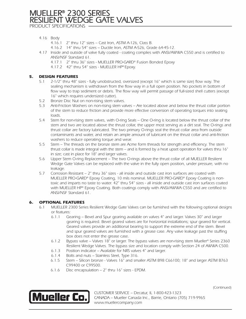
4.16 Body4.16.1 2" thru 12" sizes – Cast Iron, ASTM A-126, Class B.4.16.2 14" thru 54" sizes – Ductile Iron, ASTM A-526, Grade 64-45-12.
4.17 Inside and outside of valve fully coated - coating complies with ANSI/AWWA C550 and is certified toANSI/NSF Standard 61.4.17.1 2" thru 36" sizes - MUELLER PRO-GARD® Fusion Bonded Epoxy4.17.2 42" thru 54" sizes - MUELLER HP® Epoxy.
5. DESIGN FEATURES5.1 2-1/2” thru 48” sizes - fully unobstructed, oversized (except 16" which is same size) flow way. The
sealing mechanism is withdrawn from the flow way in a full open position. No pockets in bottom offlow way to trap sediment or debris. The flow way will permit passage of full-sized shell cutters (except16" which requires undersized cutter).
5.2 Bronze Disc Nut on non-rising stem valves.5.3 Anti-Friction Washers on non-rising stem valves – Are located above and below the thrust collar portion
of the stem to reduce friction and provide more effective conversion of operating torques into seatingloads.
5.4 Stem for non-rising stem valves, with O-ring Seals – One O-ring is located below the thrust collar of thestem and two are located above the thrust collar, the upper most serving as a dirt seal. The O-rings andthrust collar are factory lubricated. The two primary O-rings seal the thrust collar area from outsidecontaminants and water, and retain an ample amount of lubricant on the thrust collar and anti-frictionwashers to reduce operating torque and wear.
5.5 Stem – The threads on the bronze stem are Acme form threads for strength and efficiency. The stemthrust collar is made integral with the stem -- and is formed by a heat upset operation for valves thru 16"in size; cast in place for 18" and larger valves.
5.6 Upper Stem O-ring Replacement – The two O-rings above the thrust collar of all MUELLER ResilientWedge Gate Valves can be replaced with the valve in the fully open position, under pressure, with noleakage.
5.7 Corrosion Resistant – 2" thru 36" sizes - all inside and outside cast iron surfaces are coated withMUELLER PRO-GARD® Epoxy Coating, 10 mils nominal. MUELLER PRO-GARD® Epoxy Coating is non-toxic and imparts no taste to water. 42” thru 54" sizes - all inside and outside cast iron surfaces coatedwith MUELLER HP® Epoxy Coating. Both coatings comply with ANSI/AWWA C550 and are certified toANSI/NSF Standard 61.
6. OPTIONAL FEATURES6.1 MUELLER 2300 Series Resilient Wedge Gate Valves can be furnished with the following optional designs
or features:6.1.1 Gearing – Bevel and Spur gearing available on valves 4" and larger. Valves 30" and larger
gearing is required. Bevel geared valves are for horizontal installations; spur geared for vertical.Geared valves provide an additional bearing to support the extreme end of the stem. Beveland spur geared valves are furnished with a grease case. Any valve leakage past the stuffingbox does not enter the grease case.
6.1.2 Bypass valve – Valves 18" or larger. The bypass valves are non-rising stem Mueller® Series 2360Resilient Wedge Valves. The bypass size and location comply with Section 24 of AWWA C500.
6.1.3 Position indicator – Available for NRS valves 4” and larger.6.1.4 Bolts and nuts – Stainless Steel, Type 316.6.1.5 Stem – Silicon bronze - Valves 16" and smaller ASTM B98 C66100; 18" and larger ASTM B763
C99400 or C99500.6.1.6 Disc encapsulation – 2" thru 16" sizes - EPDM.
(Continued)
CUSTOMER SERVICE – Decatur, IL 1-800-423-1323CANADA – Mueller Canada Inc., Barrie, Ontario (705) 719-9965www.muellercompany.com
7. TEST PRESSURE7.1 The pressure test on each MUELLER Resilient Wedge Gate Valve meets the requirements of AWWA
Standard C509 and C515 for Resilient Seated Valves.7.1.1 Each MUELLER Resilient Wedge Gate Valve is subjected to two pressure tests. The seat test is at
the working pressure of AWWA valves and 1-1/2 times working pressure of UL Listed valves.Shell tests are at two times the working pressure.
7.1.2 Pressure tests at the working pressure shall show NO leakage past the seat from either side ofthe wedge or at the flange joints. Pressure tests at twice the working pressure shall show NOleakage through the metal or flange joints.
7.1.3 Test pressures are as follows: 2" thru 54" – 250 psi - Seat Test, 500 psi - Shell Test.
MMUUEELLLLEERR®® 22330000 SSEERRIIEESSRREESSIILLIIEENNTT WWEEDDGGEE GGAATTEE VVAALLVVEESSPRODUCT SPECIFICATIONS