Embed Size (px)
Citation preview

DF6000 Control PanelUser Manual
Fire
Assessed to: ISO 9001:2000Certification number: 714h/01
Approved to: EN54-2 1997 & A1;2006EN54-4:1997 & A1;2002 A2:2006
Document Drg Ref: PR200-04-513-15 Marketing Ref: CC1809a
0832 – CPD – 1060
DF6000 - USER MANUAL
2
Introduction to the Manual
This manual provides information on the installation, operation and maintenance of the Menvier DF6000System.
Notice
The operating system of the DF6000 may be revised as a result of enhancements to the system softwareor hardware. Revisions to this manual will be issued and supplied on request and should be logged
in the table supplied on the contents page.
Caution
Risk of explosion if battery is replaced by an incorrect type disposeof the used batteries according to the instructions
Contact
Technical: 01302 303350Service: 01302 303352Sales: 01302 303303

DF6000 - USER MANUAL
3
Contents
Section 1 - System Installation and DesignIntroduction 5Project Planning 6System Design Guidelines 7Compatible Equipment 8Detectors 9Callpoints 10Beacons and Sounders 11Base Sounder 11Stand Alone Sounders 12Loop Powered Beacon 12Compatible Interfaces 133 Channel I/O 131 Channel I/O 14Zone Monitor Unit 14Shop Monitor Unit 15Spur Isolator 164 Way Sounder Circuit Controller 16Micro Interfaces 17Fan Controller Interfaces (FC18 / FC6) 18Equipment Compatiblity 19System Overview 20Technical Specification 22Optional Functions as per EN54 Pt 2 & 4 24Optional Functions Not Approved to EN54 Pt 2 & 4 28Cable and Wiring 29Installation 30Fixing Details 31External Connections 32Networking 33Inputs/Outputs 34Maintainance 36
Section 2 - Panel Assembly InformationAttaching Panel Door 38Installing Optional Screen Door 39Replacing Printer Paper Roll 40
Section 3 - Commissioning Commissioning Mode 42Configuration 43Panel Fault Finding 44Protocol 45PC Comissioning Software 46
Section 4 - Panel Controls And Indicators System Indicators 50Panel Layout 51Touch Screen Display 52Panel Operation 53Public (Access Level 1) 54Evacuate (Access Level 2) 55Silence Alarms 56Mute Buzzer 57Reset 57Pre Alarms 58Disabled Devices 58
y
View Faults 59Enable / Disable (Others Menu) 59Print 61Lamp Test 62Weekly Test 63View Events 64Check Auto Config 65Replace Device 66Test Device 67Test Zone 68Sounder Level Test Mode 69Global LED Flashing On/Off 70One Man Walk Test 71Load CDR From Laptop 72Download CDR To Laptop 73Auto Learn 74Erase Log 75System Details 76Analogue Levels 77Printer Settings 78Change Panel Number 79Number of Panels In Network 80Screen Cover 81Programming I/O and Sounders 82Sound Settings 83Change Date/Time 84Change Address Text 85Change Zone Text 86Change Panel Text 87Configure Zones 88Change User Code 89Add Zone 90Delete Zone 91Add Device 92Delete Device 93Configure Heat Detectors 94Network 95Password Protection 96
Section 5 - AppendixSpur Isolator 984 Way Sounder Controller 99Zone Monitor Unit 100Shop Monitor Unit 1011 Way Input Output Unit 102Detector Base Wiring 103System Wiring 104IP66 Wall Sounder 105Internal Wall Sounder 106Base Sounder 1073 Way Input Output Unit 108Loop Powered Beacon 109Callpoint 110EN54 Product Spec Label 111Battery Disposal Instructions 112CE Marking 113
DF6000 - USER MANUAL
4
Section 1System Installation and Design
Section 1 - System Installation and Design

DF6000 - USER MANUAL
5
Introduction
DF6000 provides all of the sophisticated features required of a leading edge analogue addressable firesystem along with the simple operation and neat installation demanded by installers and building users.
The panel can be flush or surface mounted and the generously sized metal back box allows amplefacilities for rear or top cable entries. It is available in single two and four loop versions, with or without anintegral printer.
In addition both passive and fully functional repeater panels are available.
A comprehensive range of ancillary devices is available to operate with DF6000, including optical,ionisation, photo-thermal and heat detectors, base mounted and stand alone sounders (including an IP67version) a loop powered beacon and a wide range of input and output interfaces.
Each of the DF6000 system components has been specifically designed to operate as part of a DF6000system, this provides an assurance that the panel, the detectors, the interfaces and the ancillaries are allfully compatible with each other and that the full range of system functionality is supported by eachdevice.
Each loop of a DF6000 panel can accommodate up to 200 addresses. To comply with EN54requirements no more than 512 addresses should be connected to a single panel. Each panel canindicate upto 96 zones. Panels are available with upto 4 detection loops, up to 126 panels can benetworked together to form a single system capable of operating with over 32,000 devices.
Note: Network systems fall outside the scope of EN54.
Section 1 - System Installation and Design

DF6000 - USER MANUAL
6
Project Planning
The following is a typical program and timetable for a DF6000 installation project, once the initial orderhas been received:
1. Project MeetingInstaller and user to be present; system specifications, schematic diagram and proposed circuit drawingto be available. DF6000 Installation and Commissioning Guide to be provided.
2. Equipment FixTypically 2 week's notice is required for equipment to be delivered. Cable to be installed and bases/backboxes to be fitted. Then fire detectors, callpoints, alarm sounders, isolator units and interface units to beinstalled.
3. Address ScheduleSchedule of sensor locations to be completed by installer and returned to enable system programming.
4. Auto LearnFire panel/repeater panels to be installed and terminated. System to be powered up by installer and autolearn mode activated (see Auto Learn section). System to be tested and verified by installer, prior to finalcommissioning.
5. Final CommissioningMinimum 2 weeks notice is required from receipt of address schedule and commission request form.Cooper Fire service engineer to attend site implement/oversee the final commissioning procedures (seecommissioning section), in conjunction with the installer.
Section 1 - System Installation and Design
DF6000 - USER MANUAL
7
System Design Guidelines
GuidelinesSystems should to the relevant local standards and codes of practice, for the UK this is BS5839 Pt 1.DF6000 meets all the relevant requirements of BS5839 Pt 1: 2002. Installation planning is simplified bythe fact that every addressable DF6000 device contains an integral short circuit isolator. Care must betaken to ensure that local standards requirements regarding aspects such as loop coverage, areacovered by a single spur and cable specification are observed.
There may be certain applications in which deviations from the code may be necessary and these mustbe listed on the commissioning certificate. (See commissioning section).
Loop LengthsThe maximum permitted loop length is 2 km measured from the near to the far terminals on the DF6000motherboard PCB. There is no minimum limit to loop length. Any wiring spurs off the loop must beincluded within the 2 km limit. On long loop runs, the lengths of wiring rises and falls (between floors,down to manual callpoints) must be included. Remember to include these especially when taking looplengths from plan drawings.
Loop Loading - Total Number of AddressesThe total number of addresses per loop is 200. this includes detectors, callpoints and all otheraddressable items (e.g. MPU, MIO, loop repeaters etc.) When designing systems its recommended thatallowances are made for future expansion, Short circuit isolators are incorporated into every DF6000 loopdevice, including Smoke detectors, heat detectors, sounders, callpoints and interfaces. Therefore, nofurther fault protection is required, in the event of a single fault, none of the devices connected to the loopwill fail to operate as the fault will be isolated by the two adjacent devices. Spur connected devicesdownstream of a cable fault will cease to function.
DF6000/PR Repeater PanelsEach repeater unit requires one address and consumes no more current from the loop than a smokedetector. The repeater also requires a local mains supply and incorporates battery backup.
Loop Loading System VerificationUnless a loop loading calculation has already been carried out, please contact our technical supportdepartment (01302 303350), before starting installation to verify that a proposed loop loadingarrangement is acceptable.
Section 1 - System Installation and Design

DF6000 - USER MANUAL
8
Compatible Equipment
Section 1 - System Installation and Design
DF6000 system componentsOrder Code Description Dimensions (mm)DF6000/1 1 Loop DF6000 Panel 495 W x 400 H x 180 DDF6000/2 2 Loop DF6000 Panel 495 W x 400 H x 180 DDF6000/4 4 Loop DF6000 Panel 495 W x 400 H x 180 DDF6000/1/P 1 Loop DF6000 panel c/w integral printer 495 W x 400 H x 180 DDF6000/2/P 2 Loop DF6000 panel c/w integral printer 495 W x 400 H x 180 DDF6000/4/P 4 Loop DF6000 panel c/w integral printer 495 W x 400 H x 180 DDF6000/1/G 1 Loop DF6000 Panel Graphite finish 495 W x 400 H x 180 DDF6000/2/G 2 Loop DF6000 Panel Graphite finish 495 W x 400 H x 180 DDF6000/4/G 4 Loop DF6000 Panel Graphite finish 495 W x 400 H x 180 DDF6000/1/P/G 1 Loop DF6000 panel c/w integral printer Graphite finish 495 W x 400 H x 180 DDF6000/2/P/G 2 Loop DF6000 panel c/w integral printer Graphite finish 495 W x 400 H x 180 DDF6000/4/P/G 4 Loop DF6000 panel c/w integral printer Graphite finish 495 W x 400 H x 180 DDF6000/COV Hinged protective cover kitDF6000/PR Passive repeater for DF6000MAS850 Sounder Base 102 Dia x 40 DMASC Cover for MAS850 102 Dia x 13 DMASB870 Base Sounder Beacon 114 Dia x 36 DMASB870-NT Base Beacon 114 Dia x 36 DMAS850LPS Wall Sounder 105 L x 105 H x 95 DMAS850LPS/WP IP66 Wall sounder 108 L x 108 H x 103 DMAB870 Addressable Beacon 95 Dia x 50 DMBG813 Surface / Flush Callpoint 85 L x 85 W x 53 DMBG817 Weatherproof Callpoint 108 L x 108 W x 65 DMIO324 3 Channel I/O Device 147 L x 88 W x 57 DMIO324T 3 Channel I/O Device 1 Address 147 L x 88 W x 57 DMIO324S 3 Channel I/O Device reset on silence 147 L x 88 W x 57 DMIO1240 1 Channel Output Unit (mains rated) 180 L x 130 H x 60 DMIU871 Zone Monitor Unit 150 L x 89 H x 58 DMIU871/ IS Zone Monitor Unit Intrinsically Safe 150 L x 89 H x 58 DMSU840 Shop Unit Interface 150 L x 89 H x 58 DMSI850 Spur Isolator 112 L x 41 H x 33 DMPU424 4 Way Sounder Circuit Controller. 300 L x 300 H x 74 DMAB800 Common Mounting Base For Analogue Detectors 104 Dia x 22 DMAP820 Optical Smoke Detector 101 Dia x 33 DMAH830 Multi Mode Heat Detector 101 Dia x 43 DMAOH850 Combined Photo Thermal Detector 101 Dia x 43 DMIU872 Micro Zone Monitor Unit 63 L x 35 H x 18.5 DMCIM-C Micro Callpoint Input Module 63 L x 35 H x 18.5 DMCOM-S Micro Sounder Output Module 63 L x 35 H x 18.5 DMCOM-R Micro Output Module Resetable 63 L x 35 H x 18.5 DMICM-NF Micro Analogue Non Fire Input Module 63 L x 35 H x 18.5 D
DF6000 - USER MANUAL
9
Detectors
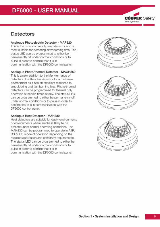
Analogue Photoelectric Detector - MAP820This is the most commonly used detector and ismost suitable for detecting slow burning fires. Thestatus LED can be programmed to either bepermanently off under normal conditions or topulse in order to confirm that it is incommunication with the DF6000 control panel.
Analogue Photo/thermal Detector - MAOH850This is a new addition to the Menvier range ofdetectors. It is the ideal detector for a multi-useenvironment as it has an excellent response tosmouldering and fast burning fires. Photo/thermaldetectors can be programmed for thermal onlyoperation at certain times of day. The status LEDcan be programmed to either be permanently offunder normal conditions or to pulse in order toconfirm that it is in communication with theDF6000 control panel.
Analogue Heat Detector - MAH830Heat detectors are suitable for dusty environmentsor environments where smoke is likely to bepresent under normal operating conditions. TheMAH830 can be programmed to operate in A1R,BS or CS mode of operation depending on therequired application and sensitivity requirements.The status LED can be programmed to either bepermanently off under normal conditions or topulse in order to confirm that it is incommunication with the DF6000 control panel.
Section 1 - System Installation and Design

DF6000 - USER MANUAL
10
Callpoints - MBG813 / MBG817
The range of purpose designed callpoints for DF6000 consists of a surface callpoint, a flush callpoint anda surface weatherproof callpoint. A range of accessories is available including a hinged protective cover,resettable element kit and a flush bezel. The status LED can be programmed to either be permanently offunder normal conditions or to pulse in order to confirm that it is in communication with the DF6000control panel.
Section 1 - System Installation and Design
Flush mounted callpointMBG813
Weatherpoof callpointMBG817
Surface mounted callpointMBG813

DF6000 - USER MANUAL
11
Sounders and Beacons
A wide range of loop powered sounders and beacons are available to operate with DF6000 consisting ofa combined sounder base with a maximum output of 95 dB(A), a standalone sounder with a maximumoutput of 100 dB(A) that is available in standard or weatherproof versions and a stand alone looppowered beacon.
For applications where a discreet dedicated sounder is required, a cover plate is available for the whitebase mounted sounder enabling it to be used as a stand alone wall or ceiling mounted sounder.
All of these devices are fully programmable via the sophisticated DF6000 multi stage cause and effectprogramming facilities.
All sounders have multiple selectable volume settings, the volume setting is controlled globally by theDF6000 panel and so can be altered without needing to access the sounder. Alternatively individualsounders can be set through the Menvier programming utility.
Base Sounder - MAS850The MAS850 has been designed specifically to complement the latest generation of Menvier softaddressed detectors. it consists of a first fix bracket, and a main body which clips onto the bracketincorporating the sounder and a detector mounting base in a single composite assembly.
After the body has been clicked into place and connected, a detector or front cover is then added tocomplete a very simple quick and neat installation. The cover enables the MAS850 to be used as adiscreet stand alone wall or ceiling mounted device. The sounder base design incorporates a mechanismthat can be activated if required to lock either the detector or the cover into place to prevent unauthorisedremoval.
Section 1 - System Installation and Design
Base sounderMAS850
Base sounder with MASC fittedMAS850
Base sounder with detector fittedMAS850

DF6000 - USER MANUAL
12
Stand Alone Sounders - MAS850LPS / MAS850LPSWPStand alone sounders are ideal for applicationswhere greater sound outputs are required than canbe achieved with a base sounder or forapplications requiring a higher level of resilience oringress protection. Two different versions areavailable standard version and an IP66 ratedversion.
Loop Powered Beacon - MAB870A loop powered flashing beacon is available forapplications where visual alarm indication isrequired such as areas of high ambient noise orbuildings which are used by people who are hardof hearing.
Base Sounder Beacon - MASB870Loop powered base sounder with a built in beaconwhere both sound and visual alarms are required.Taking 1 address
Base Beacon - MASB870-NT Loop powered base beacon where visual alarmwithout sound are required. Taking 1 address.
Section 1 - System Installation and Design
Stand alone sounder MAS850LPS
Stand alone sounder - weatherproofMAS850LPSWP
Loop powered beaconMAB870
Loop powered beaconMASB870-NT

DF6000 - USER MANUAL
13
Compatible Interfaces
DF6000 has been designed to be suitable for a wide range of applications, various interfaces have beendeveloped to enable the simple integration of other fire systems or building control and safety systems.The following devices are available:
3 Channel I/O device - MIO324MIO324 has 3 input channels and 3 output channels, it is used to monitor up to 3 separate inputs fromequipment such as sprinkler flow switches and also to provide 3 separately controlled volt free outputcontacts which are intended to be used to control external equipment such as air handling plant oraccess control systems. All inputs and outputs operate completely independently of each other and canbe programmed using the sophisticated cause and effect capabilities of DF6000 to operate either globallyor in response to activation of specific devices or specific inputs. Inputs are monitored for open and shortcircuits, a specific resistance is required to activate an alarm condition, fully open or short circuitconditions are monitored and generate a system fault signal. Inputs are suitable for use as fire signalinputs such as from a sprinkler flow switch, however they can also be used to monitor non fire inputssuch as external keyswitches. Outputs are rated to switch a maximum of 1A resistive at 30 V dc.MIO324 fixes to a standard, deep, double gang back box and can be either surface or semi recessmounted.
MIO324TThis unit is identical in build to the MIO324 but this has been designed to take 3 addresses (this can beexpensive in terms of outputs because it replies as 3 x 3 Channel I/O's), this means that text informationcan be allocated to each channel. It also allows each individual input and output to be disabled (byaddress). The maximum number of addressable MIO324T per loop is 6.
MIO324SOnce again this unit is identical with the MIO324 only taking 1 address. The programming is the same asthe MIO324. This unit was designed so that the relay outputs reset on silence rather than full reset, thusenabling the user to interface this device with other fire panels and hence prevents locking up. Themaximum number of addressable MIO324S per loop is 20.
Section 1 - System Installation and Design
3 channel I/O deviceMIO324 / MIO324T / MIO324S

DF6000 - USER MANUAL
14
1 Channel I/O device with mains rated switching capability (MIO1240)MIO1240 is a single channel input / output unit, the output is capable of switching up to 8 A at 230 V ac.Commonly used for applications such as door release controls and plant shut down signalling the input ismonitored for open and short circuits, a specific resistance is required to activate an alarm condition, fullyopen or short circuit conditions are monitored and generate a system fault signal. The input is suitable foruse as a fire signal input such as from a sprinkler flow switch, however it can also be used to monitor nonfire inputs such as an external keyswitch.
Zone monitor unit (MIU871)MIU871 is designed to enable a zone of compatible conventional detectors and callpoints to beconnected into the DF6000 loop, it is compatible with up to 20 Menvier conventional detectorsconnected via FXN520 bases. Please refer to local standards e.g. BS5839 Pt1:2002 for details of themaximum allowable area to be covered by a single spur / zone. MIU871 fixes to a standard, deep, doublegang back box and can be either surface or semi recess mounted. When semi recessed only the frontsection protrudes giving a maximum 29mm depth.
MIU871/ISSimilar to the above but the detection zone has been programmed to accept a Zener barrier and zone ofintrinsically safe detectors. End of line for this zone now becomes 6K8 and the diode in the detector basemust be removed.
Section 1 - System Installation and Design
1 channel I/O deviceMIO1240
Zone monitor unitMIU871 / MIU871/IS

DF6000 - USER MANUAL
15
Shop Unit Interface - MSU840MSU840 accepts a zone of conventional detectors plus an unlimited number of callpoints which can beconnected to the same input as the detectors or a separate callpoint input if required. There is also afacility to connect a power supply, which can then be monitored for fault.
In addition it has the facility to connect two circuits of conventional polarised sounders, which aremonitored by means of an end of line resistor and powered in alarm conditions from the external powersupply. The sounder circuits can be programmed to operate in pulsed, continuous or time delayed mode.
Please refer to local standards e.g. BS5839 Pt 1:2002 for details of the maximum allowable area to becovered by a single spur / zone.
Note: This unit must always be used with a 24 V power suply
Section 1 - System Installation and Design
Shop unit InterfaceMSU840

DF6000 - USER MANUAL
16
Spur Isolator - MSI850Enables soft addressing to work when the loop contains spurs, it controls the addressing operation sothat when the system reaches a spur, all devices on the spur are allocated an address before it continuesaddressing the loop. The device also incorporates a short circuit isolator. Because each device contains ashort circuit isolator only 1 is required at the start of each spur. MSI850 is mounted on a standard deepdouble gang back box (supplied) please refer to BS5839 Pt 1:2002 f
4 Way Sounder Circuit Controller - MPU424MPU424 provides power for 4 separately controllable conventional sounder circuits, each circuit can beseparately programmed. MPU424 is designed to greatly simplify installation in applications wherespecialist sounders or beacons are required since it powers the sounders and allows full control of thesounder operation without having to wire the sounder back to the DF6000 control panel.
A 4 way unit takes up a single address but each circuit can be independently controlled. An MPU424 unitrequires a local un-switched 230 V supply and incorporates a back up battery to 24 hours of standbyoperation followed by a minimum of 30 minutes of full alarm ringing. A standby of 72 hours can beachieved at the expense of reduced load capability.
Section 1 - System Installation and Design
Spur Isolator MSI850
4 Way sounder circuit controllerMPU424

DF6000 - USER MANUAL
17
Micro Interfaces
A range of micro interfaces modules are also available:
MCIMIs a competitively priced input module, designed to enable a Menvier panel to accept input signals fromexternal devices such as key switches and sprinkler flow switches. It is extremely compactand therefore ideal for incorporation into other equipment. The maximum number of addressable MCIM perloop is 20.
MCOMIs a competitively priced output module, designed to enable a Menvier panel control external devices suchas door holders or access control systems. It is extremely compact and therefore ideal for incorporationinto other equipment. The maximum number of addressable MCOM per loop is 20.
MIU872Is a compact single zone input, soft addressed, microinterface, incorporating integral short circuit isolators.It is fully compatible with the current range of Menvier analogue fire detection panels. It is suitable forinterfacing a zone of up to 20 conventional Menvier detectors onto a Menvier analogue fire panel. It willoperate with any Menvier conventional detector in configuration with a schottky diode type base.
MCIM-C (Identified as a Callpoint)Is a compact input module used to accept input signals from external equipment such as beam detectors,flow switches, valve monitor switches etc. The maximum number of sounder devices per loop is 200.
MCOM-S (Identified as a Sounder)Is a compact single channel output unit. This device is identified as a sounder output by a Menvieraddressable panel. The maximum number of sounder devices per loop is 60.
MCOM-RIs a compact output module used to control or signal external equipment which require removal of powerfor reset purposes. The maximum number of addressable MCOM-R per loop is 20.
MICM-NFIs a compact single channel input unit. This device is identified as a non-fire input module by the Menvieraddressable panel. The maximum number of addressable MICM-NF per loop is 200. Complex cause andeffect can still be achieved using the latest site installer software without any indication on the panel.However the action will still be seen in the event log. Ideally suited for non fire applications.
Section 1 - System Installation and Design
Micro interfacesMCIM / MCOM / MIU872 / MCIM-C / MCOM-S / MCOM-R / MICM-NF

DF6000 - USER MANUAL
18
Fan Controller Interfaces (FC18 / FC6)
FC18 and FC6 Interface is designed to work with the Menvier range of analogue fire alarm control panels,providing the capability to control and display the status of AHU fans.
FC18 and FC6 Interface is connected to a Menvier analogue addressable fire alarm control panel bymeans of the comms loop, utilizing only one address whilst providing the ability to monitor and control upto six AHU Fans.
Each FC6 and FC18 Interface incorporates its own CPU specifically configured to control the relevantinput and output logic making programming quick and easy via the ‘CAPPER’ software or site installer.
Using the CAPPER software or site installer, each individual Fan Control channel on the FC6 isprogrammed to an output and feedback input field device to control and monitor the status of an AHUfan.
Features> Convenient loop mounting> Comprehensive LED display> Surface/rack mounting options> Key operated auto/manual operation> Comprehensive software cause and effect
Section 1 - System Installation and Design
Fan controller interfaceFC6
Fan controller interfaceFC18

DF6000 - USER MANUAL
19
Equipment Compatibility
DetectorsLoop wired detectors must be of the Menvier 800 series soft addressed analogue type. FXN500 seriesconventional detectors can be connected via an MIU871 interface. The connection of other detectortypes via an MIU871 interface is not recommended.
CallpointsLoop wired callpoints must be the Menvier 800 series soft addressed analogue type, FX200 seriesconventional callpoints can be connected via an MIU871 interface. The connection of other callpointtypes via an MIU871 interface is not recommended.
SoundersLoop powered addressable sounders must be of the Menvier 800 series soft addressed analogue type.Conventional sounders can also be connected either to the conventional sounder circuits at the panel orto the loop via a MPU424 addressable sounder controller interface providing they meet the following:1. They are suitable for operation between 18 V and 28 V.2. They are polarised and suppressed.3. The total alarm load is less than the rating of the panel / alarm power interface.Note:It is possible to use devices outside these requirements if they are supplied with power from a separatesource and switched via a suitable relay.
Relay circuitsAdditional relays can be added to the DF6000 system by using either MIO1240 or MIO324 relay units.Relays / Auto-dialers and auxiliary equipment A wide variety of relays and other equipment can beconnected to the DF6000 system, but you should note the following constraints:1. DF6000 provides monitored outputs to drive fire and fault relays mounted in external equipment.
External relays should be suppressed. If a non-suppressed relay is used then a diode can be connected. to suppress any reverse EMF on the release of the relay which might cause the panel to malfunction.
2. A 24 V dc output is provided at the panel to make it easy to connect ancillary equipment. Although thepanel can supply a continuous quiescent load of up to 30 mA, BS5839 precludes this practice and any ancillary equipment you connect should only consume power in the alarm or fault mode to meet the requirements of BS5839.
Additional instructions for electromagnetic compatibilityWhen used as intended this product complies with EMC Directive (89/336/EEC) and the UK EMCregulations 1992 (SI 2372/1992) by meeting the limits set by the standards BS5406 (Pt 2 & 3) 1988,EN50130-4 immunity and EN 61000-6-3 emission requirements. The following installation guidelinesmust be followed.1. External cables must be connected using the cable entries or knockouts provided.2. When routing external cables inside the product they must be
a) Kept as short as possibleb) Routed close to the housingc) Kept as far as possible from the electronics
Any modifications other than those stated in this manual, or any other use of this product may causeinterference and it is the responsibility of the user to comply with the EMC and low voltage directives.
Section 1 - System Installation and Design

DF6000 - USER MANUAL
20
System Overview
Simple User InterfaceThe main element of the user interface with DF6000 is a large (120mm x 90mm visible area) touch screendisplay, which provides comprehensive user information and also acts as a multifunctional keypad.
Comprehensive context sensitive help information is provided throughout the menus to assist unfamiliarusers with system operation.
The DF6000 touch screen display automatically reconfigures to suit the selected function, for example, ifthe change device text menu option is selected, the touch screen is automatically formatted as a fullQWERTY keyboard to enable fast and simple text entry.
The use of the touch screen display enables a wide range of user and engineering facilities to beincorporated into the panel whilst still offering simple operation.
As well as a large format LCD display providing full system status information, the panel incorporates 96traditional zone indication LED's to provide clear information about the status and spread of a fire even toa user who is completely unfamiliar with the operation of the system.
In addition there are a number of system status LED's designed to give clear status information to nontechnical users.
User Configuration And Maintenance FacilitiesDF6000 has comprehensive facilities for on site system configuration, whereby the user can add orremove simple devices or change device text directly via the panel, without the need for a serviceengineer to visit site. For initial configuration or major system changes special PC configuration softwareis available enabling Cooper Lighting and Safety personnel to do this more efficiently than can beachieved using the system screen. Exiting configurations can be uploaded to the PC so that changes canbe made to the existing system rather than having to revert to initial files.
Sophisticated Sounder Control FacilitiesDF6000 has the ability to support highly complex ringing pattern requirements. Multistage cause andeffect programming is possible whereby each addressable sounder or output interface can beprogrammed independently if required and can be set to respond to specific addresses, specificdetection zones, specific panels on a networked system or standard global ringing.
The panel supports 3 separate sets of programming per sounder and each stage can be triggereddifferently For example, if a single detector is triggered the panel can be programmed such that thesounder nearest to the detector operates immediately and continuously, the remaining sounders in theaffected zone operate in pulsed mode and the other sounders delay for a selectable period to allow thecause of the alarm to be investigated before global ringing commences.
Section 1 - System Installation and Design

DF6000 - USER MANUAL
21
Spur Tolerant Soft AddressingDF6000 utilises intelligent soft addressing technology to greatly simplify the installation andcommissioning processes. Once the system has been installed and the autolearn menu selected, theDF6000 control panel will automatically scan the detection loops and allocate each device with anaddress number corresponding with its position on the loop, this avoids the traditional need for manualaddressing of the system devices which is time consuming and provides a potential for error.
A major innovation with DF6000 is the ability to incorporate spurs of analogue devices which are fed fromthe main loop by utilising a spur isolator. Whenever the panel detects a spur, it breaks from allocatingaddress numbers to the loop wired devices, allocates address numbers to each of the devices on thespur in sequence and then continues to address the devices on the main loop. Every DF6000 analoguedevice incorporates an integral short circuit isolator ensuring maximum system integrity. A single shortcircuit will not disable any loop-mounted devices, the isolators in the devices each side of the short circuitwill operate and the DF6000 control panel will drive communication from both ends of the loop. The spurisolator also incorporates a short circuit isolator such that in the event of a short circuit on the spur, theintegrity of the main loop will not be compromised. Please refer to local standards e.g. BS5839 Pt1:2002for details of the maximum allowable are to be covered by a single spur.
Simple Future ExpansionDF6000 is designed to ensure simplicity of future expansion. If an additional device is added after thesystem has been programmed, the DF6000 will allocate the next available address, it will not alter any ofthe existing address numbers allocation thus enabling simple updating of as fitted drawings etc. Similarlyif a device is removed, the relevant address is saved as a spare address for future use, the addresses ofthe remaining devices are not altered.
Integral Power Supply and BatteryThe DF6000 panel is designed for ease of installation, the power supply and battery are integral to themain control panel so only a single panel is required even on large 4 loop systems.
Optional PrinterDF6000 panels are available with optional built in printers. Where a printer is fitted, it is housed behind aprinter cover door, which can be opened by means of a special tool (supplied) to provide simple and safeaccess to the printer paper roll without exposure to any live equipment. Paper replacement is extremelysimple due to the drop in loading method and auto feed printer design, the paper roll is simply droppedinto the purpose designed cradle and the end of the roll is then offered up to the printer, which will thenautomatically load the paper ready for use. The printer can be set to either print automatically or to printon demand When a printer is not fitted, a removable, flush fitting blanking plate is used to cover theprinter paper aperture to enhance the appearance of DF6000 and to preserve its ingress protectionrating.
Optional Hinged Lockable CoverWith a standard panel, access to all panel functions is controlled by a series of pass codes, which areentered via the touch screen display, for maximum security, a facility is built into the DF6000 to enable theuser to alter the user pass code as required. For applications where a high level of resilience is required, aclear hinged lockable front cover is available which allows the screen and all of the system statusindicators to be clearly seen but prevents access without first unlocking the cover. A single concealedlocking mechanism provides access to both the printer door and the optional display cover where ahinged cover is fitted, additional buttons are provided to scroll the display and to silence the fault buzzerwithout opening the lockable cover
Section 1 - System Installation and Design

DF6000 - USER MANUAL
22
Technical Specification
Section 1 - System Installation and Design
Power Supply (Approved EN54 pt 4)MainsNominal voltage 230 Vac + 10%, -15%Nominal current 75mAMaximum current 750mAInput fuse R1 NTC SG39 Imax 4 AmpOutput voltage including tolerances 26 V = 18.5 to 29.5 V
26 V RAW = 18.5 V to 29.5 V5 V Output = 4.6 V to 5.5 V
Ripple voltages 26 V = 800m V26 V RAW = 800m V5 V Output = 430m V
Maximum loadings 26 V O/P = 0.98A26 V RAW O/P = 1.7A5 V = 0.5A
Standby current (4 loops loaded) 26 V = 280 mA26 V RAW = 150 mA26 V = 280 mA26 V RAW = 150 mA5 V = 43 mA
DF6000 is protected by an internal thermal device, this requires no maintenance* I max a, I max b and I min = Current as specified in BSEN54-4 Published 2006 (amendments 1 and 2)BatteriesNumber of batteries 2Manufacturer YUASA NP12-12Capacity 12 AhBattery fuse 6.3A Anti-Surge (F4)Maximum battery current 3.5 AmpsStandby current (mA) 175 (4 loops), 125 (2 loops)Maximum charging current to the batteries 1.0ampFloat voltage 27.4 VFinal voltage 21.0 VCharging characteristics Constant voltage with 0.970A
limit with temperature compensation
Maximum current drawn from the batteries (when the mains is not available) 3.5AmpsDeep discharge protection 20.6 VBattery Internal Impedance Fault >0.5 ohmsInputsAddressable loopsMax number 1 - 4Max loop load per loop 220 maMax number of addressable devices per Loop 200Class change Operated by external volt free contact

DF6000 - USER MANUAL
23
Terminal Blocks: Do not use excessive force when tightening the screws on the terminal block
Risk of explosion if battery is replaced by an incorrect type dispose of the used batteriesaccording to the instructions
Section 1 - System Installation and Design
OutputsConventional sounder circuitsNumber of sounder circuits 4Total sounder Load 1.5 AmpsSounder circuit fuses (F1/2/3/4) 1.6 Amp (Quick Blow)End of line resistor 6k8Fire Protecting EquipmentMax load 60 maFused (PTC3) 100mA polyswitchEnd of line resistor 6k8Fault Routing EquipmentMax load 30 maFused (PTC1) 100mA polyswitchEnd of line resistor 6k8Auxiliary Relays - The auxiliary relays provide fused volt free change over contacts. These contacts are not monitored.Max load 24 V 1 AmpFuse (PTC4) 1.35 Amps polyswitchAuxiliary 24 V SupplyNominal voltage 24 V ±10%Fuse (PTC5) 100 mA polyswitchMaximum current 30 mAThis output is not to be used for fire protecting equipment or fire alarm routing equipment any power taken from the alarm system will effect the standby durationRS485 Port - Serial output port for driving DF6000 repeater panels, mimics etc.. This output is short circuit protectedMax cable length 2 KmMin recommended cable size 1mm² (Screened)RS232 Port - Serial output port for driving DF6000 repeater panels, mimic etc. This output is short circuit protectedPrinter (Optional)Type High speed thermalNumber of characters per line 40Type of paper 58mm x 46mm Thermal RollReplacement paper roll order code ADF6PRINTERPAPERMechanical SpecificationWeight incl batteries 18kg, excl batteries 9kgDimensions (standard batteries) 495mm(L) x 395mm(H) x 180mm(D)Type of material (backbox) Mild Steel (power coated)Type of material (Facia) PC/ABSFlammability rating UL 94 V0Total number of knockouts 51Diameter of knock out 20mmAnti-Tamper cover (optional) Weight : 250g
Material used : Poly CarbonateFlammability rating : UL 94 5VA

DF6000 - USER MANUAL
24
Optional Functions as per EN54 Pt 2 & 4
DF6000 is approved to EN54 Parts 2 & 4 including all the following options which can be selected asrequired
Panel Outputs
Panel Sounders: (option 7.8 EN54 Pt 2)Two pairs of outputs are provided. ONLY polarised equipment should be used. Ensure the polarity of theconnections are observed at all times and end of line resistors (6K8 5%) are fitted for correct operation.The total alarm load across all sounder outputs = 1.5 Amp All outputs are fused with 1.6 Amp Glass fuseAlarm devices should be spread equally across the 4 sounder circuits.WARNING: Do not exceed the rated output current
Output Fire Alarm Routing Equipment (option 7.9 EN54 Pt 2)This output, which is fused, and monitored using a 6.8k end of line resistor, is used for the automatictransmission of the fire signals to fire alarm routing equipment (e.g. fire brigade). It operates by providing24 V output to an auxiliary device (e.g. relay). It is current limited to 30 mA using a resettable polyswitch.Class change and test conditions do not operate this output. If operated under a fire alarm condition, theindication will be displayed on the Touch screen display and will remain until the fire alarm is reset. Ensurethe polarity of the connections are observed at all times and end of line resistors (6k8 5%)are fitted for correct operation.
Output to Fire Alarm Protecting Equipment (option 7.10 EN54 Pt 2)This output, which is fused, and monitored using a 6.8k end of line resisters used for the transmission ofthe fire signals to controls for automatic fire protecting equipment (e.g. Door released units etc). Itoperates by providing 24 V output to an auxiliary device (e.g. relay). It is current limited to 30 mA using aresettable. polyswitch. Class change and test conditions do not operate this output. If operated under afire alarm condition, this output remains energised until the fire alarm is reset. Ensure the polarity of theconnections is observed at all times and end of line resistors (6k8 5%) are fitted for correct operation.
Output to Fault Warning Routing Equipment (option 9.4.1c EN54 Pt 2)This output, which is fused and monitored using 6.8k end of line resistor, is used for thetransmission of fault signals to fault warning routing equipment This output is monitored using 6k8end of line resistor and it current limited to 30 mA.Under normal condition it operates by providing12 V dc which can be connected directly to a 12 V auxiliary device (relay). It is current limited to 30 mA.Under fault conditions or even if the DF6000 is powered down, this output will be switch to OV.Ensure the polarity of the connections is observed at all times and end of line resistors (6k8 5%)are fitted for correct operation.
Delays to Outputs (option 7.11 of EN54 Pt 2)The DF6000 has the option to delay the operation of panel sounders, the fire routing equipment outputand the fire protecting equipment. This delay is selectable using the DF6000 site installer downloadsoftware .The delay is configurable in increments of 1 minute up to a maximum of 10 minutes.This delay can be enabled and disabled at access level 2. The DF6000 has the facility for a specificcallpoint to override this delay by programming this callpoint via an input interface to provide an evacuatesignal using DF6000 site Installer.
Section 1 - System Installation and Design

DF6000 - USER MANUAL
25
Dependencies on More Than One Alarm Signal - Type C (option 7.12.3 of EN54 Pt 2)The DF6000 has the facility to inhibit the operation of the output sounders, output to fire routingequipment and the output of the fire protecting equipment until one more confirmatory signals arereceived from different zones. This feature is programmable using DF6000 site installer software.
Alarm Counter (option 7.13 EN54 Pt 2)The panel records the number of instances that it enters the fire alarm condition. This is abbreviated in thetouch screen by "AC" and it is displayed in the fire window at access level 2. This counter can only bereset by the manufacturer.
Optional Auxiliary Board VDS Requirement (option not required by EN54)This board can be connected to an extinguishing system as well as a fire brigade control panel.This board has been tested and approved in according with DIN14661 and DIN 14675.
Input / Outputs to Fire Brigade Panel
Outputs
Output 1: Fire Protecting Equipment Operated "Extinguishing On"This output is ON in alarm condition to indicate that the DF6000 control and indicating equipment has operated the fire protecting equipment (option 7.10 of EN54 Pt 2).
Output 2: Fire Routing Equipment Operated "Fire Brigade Link" This output is ON in alarm condition to indicate that the DF6000 control and indicating equipment has operated the fire routing equipment (option 7.9 of EN54 Pt 2).
Output 3: Disablement of Fire Protecting Equipment This output is ON to indicate that the fire protecting equipment has been disabled either by the DF6000 control and indicating equipment or the fire brigade panel.
Section 1 - System Installation and Design

DF6000 - USER MANUAL
26
Output 4: Disablement of the Fire Routing Equipment This output is ON to indicator that the fire routing equipment has been disabled either by theDF6000 Control and indicating equipment or the fire brigade panel.
Output 5: Reset from Fire Alarm Condition This output is ON to indicate that the DF6000 control and indicating equipment is in alarm condition. This output will remain on for at least 15mins after reset or when the reset has been activated from the fire alarm brigade panel
Output 6: Disablement of SoundersThis output is ON to indicate that the sounders have been disabled either by the DF6000 control and indicating equipment or the rire brigade panel
Inputs
Input 1: ResetThis input is used to reset the control and indicating equipment
Input 2: Testing of Fire Routing EquipmentThis input is used to test the output to the fire routing equipment
Input 3: Disablement of the Fire Routing EquipmentThis input is used to disable the fire routing equipment if the DF6000. Once the FRE is disabled from this interface, it can never be enabled from the DF6000 control panel
Input 4: Disablement of the Fire Protecting EquipmentThis input is used to disable the fire protecting equipment of the DF6000. Once the FRE is disabled from this interface, it can never be enabled from the DF6000 control panel
Input 5: Disablement of SoundersThis input is used to disable the sounders of the DF6000. The disablement of sounders fromthe fire brigade panel can be re-abled from the DF6000 control panel only when the system is not Alarm State.
Section 1 - System Installation and Design

DF6000 - USER MANUAL
27
German Interface Electrical Characteristics
InputsThe inputs are designed to be actioned in one of two ways, see list below:
First: A change in logic state ie. switch toggled on / off.Second: Logic pulse ie. nominal state logic high, then logic low > 200mS then return to logic high.
all inputs are held high via a weak pull up (logic high), the action of short circuiting any of the five inputs tothere respective 0v will result in a logic low.
1: reset -> logic pulse2: FRE relay test -> logic pulse3: FPE disable -> logic state change4: FRE disable -> logic state change5: Acoustic disable -> pulse logic
Monitored InputsIn Fault / Extinguisher Active
-> End Of Line resistor 3K3.-> 680 Ohm across input to actiavte input
Relay Outputs
Normal status -> Input sees a 3K3 resistor.Active status -> Input sees a 680 ohm resistor.
Outputs1: Extinguisher released -> output high 26 V2: FRE operated3: FPE disabled4: FRE disabled5: Panel in fire, will remain on after panel soft reset for > 15 minutes, or extinguish immediately with
interface reset6: Disable all sounders.
Section 1 - System Installation and Design

DF6000 - USER MANUAL
28
Optional Functions Not Approved to EN54 Pt 2 & 4
Italian Mode: (option not required by EN54 Pt 2)This mode can be programmed at access level 3. This relates to points 12.2(a) and 12.2(b) of the InternalItalian Ministerial Decree 9th April 1994 which states that in the event of a fire detection from 2 or moredetectors or from an MCP there should be a 2 minute delay before output activation otherwise in theevent of a fire detection from any one detector there should be a 5 minute delay before output activation,provided that the fire event is not acknowledged. These delays apply to siren activation as well as theshutting down/activation of other external equipment and additionally the legislation states that thesedelays should be adjustable depending on the type of activity being carried out within the building.
For example, if there was a fire detected from a single detector then we should start a 5-minute(adjustable) delay (T2). If however a fire is detected from a second detector or a call-point the delayshould automatically revert to 2 minutes (adjustable) (T1). In this scenario the value of (T1) is critical. Tokeep things simple, let's assume that we set T1 = 2 minutes and T2 = 5 minutes.
Swedish Mode (option not required by EN54 Pt 2)This mode is programmed at access level 3. One of the Swedish requirements is that access level 2 and3 is only avalailabe by the access of the keyswitch. The key switch is wired to the class change input.
Commission per Loop (option not required by EN54 Pt 2)This mode is programmed at access level 3. This allows the commissioning engineer to auto learn oneloop at the time
Alarm Verification (option not required by EN54 Pt 2)This mode is programmed at access level 3.This has the flexibility to delay the activation of detectors by30 seconds. In the event of an alarm from a detector, the led of the detector will be illuminated and noalarm will be displayed on the panel. The detectors are checked continuously for 30 seconds. If after thistime, the detector is still in alarm, the output will be activated otherwise the detector will be reset.
Timer T1/T2 (option not required by EN54 Pt 2)This mode is set on at access level 3 and is a commonly used by eastern european countries.
In the event of a fire the timer T1 can be set from 0 to 3 min where the alarm will be displayed on thepanel and no output activation, if during this time the alarm is acknowledged then timer T2 can be setfrom 0-10 min where the alarm can be investigated and alarm reset. However if timer T1 and T2 time outduring alarm activation, the outputs will be activated.
Timer T1/T2 with callpoint Override (option not required by EN54 Pt 2)This is similar to the above except a callpoint alarm will activate the output instantly
Section 1 - System Installation and Design

DF6000 - USER MANUAL
29
Cable and Wiring
Only the cable types listed below are allowable for loop connections.1. Enhanced Fire TUF2. Fire TUF™3. FP2004. MICC
When choosing your preferred cable type, you must take note of the following cable and wiringrequirements.1. The cable must be 2 core screened with an over sheath.2. Maximum loop length with any of the above cables is 2 km3. Maximum volt drop must be limited to 7 V.4. The conductors should be 1.5mm minimum an no larger than 2.5mm5. Multicore cable should not be used for detector wiring.6. Different loops should NEVER be run within the same cable.7. Loop feeds and returns should never be used within the same cable.
Cable Resistance
Cable AnchorageThe mains cable must be fixed securely with a 20mm cable gland. Remove a suitably located knockoutfeed the cable through the gland and bolt the gland to the DF6000 backbox as shown. Secure the cableto the side of the box using the cable clip provided.
NOTE: The mains cable tail ends must be insulated to prevent dangerous conditions arising in the eventof accidental switching on of the mains supply.
Section 1 - System Installation and Design
Core Diameter Typica l FP200 Resistance1.0mm² 18.1 Ohms/km/Core1.5mm² 12.1 Ohms/km/Core2.5mm² 7.41 Ohms/km/Core4.0mm² 4.61 Ohms/km/Core

DF6000 - USER MANUAL
30
Installation
the panel should be installed in a clean, dry, reasonably well ventilated place, and not in direct sunlight.Temperatures in excess of 40°C and below 5°C may cause problems, if in doubt consult Cooper Lightingand Safety. The panel should be located away from any potential hazard, in a position where it is readilyaccessible to authorised staff, and the fire services, ideally on the perimeter of a building near apermanent entrance. Mount the panel to the wall using the drill template provided. Do not drill through thepanel to the wall as dust will contaminate the circuitry.
Installation Guide! Never carry out insulation tests on cables connected to electronic equipment.! DO NOT OVER TIGHTEN TERMINAL CONNECTOR SCREWS! Always use the correct type of cables specifically designed for the operation of fire detection and
alarm circuits.! Always adhere to volt drop limitation when sizing cables! Always observe polarity throughout. Non colour coded conductors should be permanently identified.! Screen continuity must be maintained throughout the entire loop circuit including at each junction
point and at each device, terminals are provided on each device to facilitate this.! The screen should be earthed at the connection point provided at the DF6000 panel and not at any
other point. Both the loop start and the loop end must be connected to the appropriate earthing points. Care must be taken to avoid connecting the screen to the earthed body of any metal devices, enclosures or cable containment. The screen or drain wire of the loop cables should not be considered as safety earth and therefore should not be connected to terminals marked with the earth symbol, except at the panel, and should not be insulated with green and yellow sleeving.
! DF6000 utilises intelligent soft addressing technology to greatly simplify the installation and commissioning processes. Once the system has been installed and the autolearn menu selected, the DF6000 control panel will automatically scan the detection loops and allocate each device with an address number corresponding with its position on the loop, this avoids the traditional need for manual addressing of the system devices which is time consuming and provides a potential for error.
! It is of vital importance that accurate details are kept of the exact wiring route in order to determine which address has been allocated to each device.
Section 1 - System Installation and Design

DF6000 - USER MANUAL
31
Fixing Details
Read all the installation instructions before commencing with the installation. The installation of this panelmust be carried out by a suitably qualified /trained person. Theinstallation must comply with IEE wiringregulations and with BS5839 Pt 1 2002 The electronic components within the fire panel are StaticSensitive. Do not touch the electronics directly.
Mounting the BackboxThe DF6000 can be flush mount or surface mounted.
1. Surface Mount: Drill four holes and fix the backbox to the wall.
2. Flush Mount: The backbox requires a hole 364 x 472 with a depth of 117mm (standard battery / backbox ) or 217 mm if deep backbox is used.
Installing CablingOnce the backbox is mounted the next stage is to install the power and loop cables and fit the glands.
Section 1 - System Installation and Design
364mm
227mm
309mm
472mm
479mm
400mm
117mm
132mm

DF6000 - USER MANUAL
32
External Connections (Mains Supply)
The mains supply should be installed in accordance with the current edition of the IEE wiring regulations.Connection to the mains supply must be via an isolating device (e.g. an isolating fuse rated at 3Ampsmaximum) reserved solely for the fire alarm system. The cover should be coloured red and labelled “FIREALARM - DO NOT SWITCH OFF”. The isolating protective device should be secure from unauthorisedoperation and ideally installed in a securely closed box with a breakable cover.
An additional warning label should be provided, depending on whether:
1. The isolating protective device is fed from the live side of the main isolating device in which case the label on the isolating protective device, should read in addition - “WARNING: THIS SUPPLY REMAINS ALIVE WHEN THE MAIN SWITCH IS TURNED OFF”. A further label should be placed on the mainisolating device reading “WARNING: THE FIRE ALARM SUPPLY REMAINS LIVE WHEN THIS SWITCHIS TURNED OFF.
Or
2. If the isolating protective device is fed from the dead side of the main isolating device, a label should be fixed to the main isolating device reading “WARNING: THIS SWITCH ALSO CONTROLS THE SUPPLY TO THE FIRE ALARM SYSTEM”.
Distributed Power Supplies The above also applies to any distributed power supply (i.e. mains connections for DF6000/PR repeatunits MPU424 relay units, etc.)
Cable SegregationAll cables for the fire alarm system should be segregated from any other cables/wiring/services.
Wiring configurationsSpurs can be taken off the loop in the following ways:
1. MIU871 Addressable Interface - Allows up to 20 conventional smoke detectors and unlimited FX201 / 203 callpoints.
2. Direct Loop Spur Wiring - Allows a zone of analogue detectors and callpoints to be directly spurred offthe loop
Note: The mains cable tail ends must be insulated to prevent dangerous conditions arising in the eventof accidental switching on of the mains supply.
Section 1 - System Installation and Design

DF6000 - USER MANUAL
33
Networking
Up to 126 DF6000 panels or passive repeaters can be networked together to operate as a singlenetworked system. To achieve this each panel must be fitted with a network card (supplied at additionalcost.)
When operating as a networked system all fire and fault event information is displayed at every panel,silencing and resetting of alarms can also be carried out from any panel on a networked system if panelsare suitably configured.
Networked panels are connected using a loop topology illustrated, or radial.
Networked panels can be used as active repeaters, alternatively a low cost passive repeater is available.This can either be connected a loop of an individual panel or it can be connected to the network. Therecommended network cable for the network connection between panels is an enhanced Firetuf cableManufactured by Draka cables (part number 910234). Screen continuity must be maintained throughoutthe entire network circuit including at each junction point. The screen should only be earthed at theconnection point provided at the first panel and not at any other point. The screen or drain wire of thenetwork cable should not be considered as a safety earth and therefore should not be connected toterminals marked with the earth symbol, except at the panel, and should not be insulated with green andyellow sleeving.
Where the network cable passes between buildings, screen continuity should not be maintained frombuilding to building. A booster device must however be used irrespective of cable length and should befitted at a suitable point in the link between buildings. The cable screen should be connected to the earthof one panel in each building.
Section 1 - System Installation and Design
PowerON
PowerON FIREFIRE General
FAUL TGeneralFAUL T
SystemDISABLESystem
DISABLESystemFAUL T
SystemFAUL T
SystemTEST
SystemTEST
ChargeFA UL T
ChargeFA UL T
BatteryFAUL TBatteryFAUL T
1 2 3 4 5 6 7 8 9
2121 2222 2323 2424
1010 1111 1212
1313 1414 1515 1616 1717 1818 1919 2020
2525 2626 2727 2828 2929 3030 3131 3232 3333 3434 3535 3636
3737 3838 3939 4040 4141 4242 4343 4444 4545 4646 4747 4848
4949 5050 5151 5252 5353 5454 5555 5656 5757 5858 5959 6060
6161 6262 6363 6464 6565 6666 6767 6868 6969 7070 7171 7272
7373 7474 7575 7676 7777 7878 7979 8080 8181 8282 8383 8484
8585 8686 8787 8888 8989 9090 9191 9292 9393 9494 9595 9696
Zone sZone s
CF3000 ANALOGUE ADDRESSABLE FIRE P ANE LCF3000 ANALOGUE ADDRESSABLE FIRE P ANE L
Designed to EN54 parts 2 & 4Designed to EN54 parts 2 & 4
PowerON
PowerON FIREFIRE General
FA UL TGeneralFA UL T
SystemDISABLESystem
DISABLESystemFA UL T
SystemFA UL T
SystemTEST
SystemTEST
ChargeFA UL T
ChargeFA UL T
BatteryFAUL TBatteryFAUL T
1 2 3 4 5 6 7 8 9
2121 2222 2323 2424
1010 1111 1212
1313 1414 1515 1616 1717 1818 1919 2020
2525 2626 2727 2828 2929 3030 3131 3232 3333 3434 3535 3636
3737 3838 3939 4040 4141 4242 4343 4444 4545 4646 4747 4848
4949 5050 5151 5252 5353 5454 5555 5656 5757 5858 5959 6060
6161 6262 6363 6464 6565 6666 6767 6868 6969 7070 7171 7272
7373 7474 7575 7676 7777 7878 7979 8080 8181 8282 8383 8484
8585 8686 8787 8888 8989 9090 9191 9292 9393 9494 9595 9696
Zone sZone s
CF3000 ANALOGU E A DDRESSABLE FIRE PA NE LCF3000 ANALOGU E A DDRESSABLE FIRE P ANEL
Designed to EN54 parts 2 & 4Designed to EN54 parts 2 & 4
Network Cable
A B X Y
A B X Y Network
Card
(Panel 2)
Network
Card
(Panel 1)

DF6000 - USER MANUAL
34
Input/Outputs
Panel InputsClass Change: (option not required by EN54)A pair of terminals are provided for class change. By shorting these terminals together (e.g. switch, timeclock) the alarm will sound (panel sounders + loop sounders only). The panel will not indicate a fire. Thealarm will cancel when the short circuit is removed. If the short circuit is not removed the alarms will notcancel.WARNING: No voltage should be applied to this input
Panel OutputsPanel Sounders: (option 7.8 EN54 Pt 2)Two pairs of outputs are provided. ONLY polarised equipment should be used. Ensure the polarity of theconnections are observed at all times and end of line resistors (6k8 5%) are fitted for correct operation.The total alarm load across all sounder outputs = 1.5 Amp all outputs are fused with 1.6 Amp glass fusealarm devices should be spread equally across the 4 sounder circuits.WARNING: Do not exceed the rated output current
Output Fire Alarm Routing Equipment (option 7.9 EN54 Pt 2)This output, which is fused and monitored using a 6.8k end of line resistor, is used for the automatictransmission of the fire signals to fire alarm routing equipment (e.g. fire brigade). It operates by providing12 V output to an auxiliary device (e.g. relay). It is current limited to 30 mA using a resettable polyswitch.Class change and test conditions do not operate this output. If operated under a fire alarm condition, theindication will be displayed on the touch screen display and will remain until the fire alarm is reset. Ensurethe polarity of the connections are observed at all times and end of line resistors (6k8 5%) are fitted forcorrect operation.
Section 1 - System Installation and Design
-+
clas
s ch
ange
Switch/Contactorb timer etc.(Apply NO voltage)
Both sounder circuits mustbe terminated with a
6800 Ohm end of line resistor
All sounders must be polarised

DF6000 - USER MANUAL
35
Output to Fire Alarm Protecting Equipment (option 7.10 EN54 Pt 2)This output, which is fused and monitored using 6.8k end of line resistor is used for the transmission ofthe fire signals to controls for automatic fire protecting equipment (e.g. Door release units etc).It operatesby providing 24 V output to an auxiliary device (e.g. relay).
It is current limited to 30 mA using a resettable polyswitch. Class change and test conditions do notoperate this output. If operated under a fire alarm condition, this output remains activated until the firealarm is reset. Ensure the polarity of the connections is observed at all times and end of line resistors (6k85%) are fitted for correct operation. All activated devices must be polarised.
Output to Fault Warning Routing Equipment (option 9.4.1c EN54 Pt 2)This output, which is fused and monitored using 6.8k end of line resistor is used for the transmission offault signals to fault warning routing equipment This output is monitored using 6k8 end of line resistor andit current limited to 30 mA.
Under normal conditions it operates by providing 24 V dc which can be connected directly to a 24 Vauxiliary device (relay). It is current limited to 30 mA. Under fault conditions or even if the DF6000 isswitched off, this output will switch to 0 V. Ensure the polarity of the connections is observed at all timesand end of line resistors (6k8 5%) are fitted for correct operation.
Auxiliary Relay (option not required by EN54)This output is a volt free contact, which is protected by a polyswitch. It is rated at 24 V 1 Amp. If operatedunder a fire alarm condition , this output will remain energised until the fire alarm is reset.
Auxiliary DC Output (option not defined by EN54)A 24 V dc output is provided. This output is protected by a polyswitch. This output can be used to powerfire or fault auxiliary equipment. Please ensure that all equipments connected to this output will only drawcurrent when a fire condition exists.WARNING: Do not exceed the rated output current
Mimic Output (option not required by EN54)This RS485 output is used to send data to a mimic display or a repeater panel. The maximum distance is2 km.
Section 1 - System Installation and Design

DF6000 - USER MANUAL
36
Maintainance
Daily InspectionCheck that only the green “POWER ON” indicator shows. Inspect for any fault indication. Notify any faultsto a system supervisior.
Weekly TestCheck indicators. Press supervisor mode on the top left of the touch screen. Enter passcode. Select“others” tab. Press the button labeled weekly test, confirm you wish to perform the test and the amber“System Test” LED will light. The panel will stay in the weekly test mode for 5mins before resetting. Duringthe weekly test, trigger a smoke detector or callpoint and check the fire panel registers the device andilluminates the correct zonal indicator. Trigger a different device every time a weekly test is performedensuring devices are tested in rotation until all have been checked. It is advisable to develop a detailed abuilding plan highlighting devices and locations to aid testing. The panel will reset automatically once the5mins have elapsed. If no devices are triggered during the weekly test the panel will abort the test andreset after 5mins. Record weekly test in the table provided in the log book.
Quarterly TestCheck all previous log book entries and verify that remedial action has been taken. Carry out the weeklytest. Visually examine the batteries and their connections, by loosening the screws behind printer doorand opening the hinged front from the right hand side. Disconnect the mains supply and check that thebatterry is capable of supplying the alarm sounders, by operating a callpoint.
Annual TestAs weekly test and quarterly test above. Additionally test all sensors and callpoints and check operation.
Every 2-3 YearsReplace or return the smoke detectors for cleaning to ensure correct operation and freedom from falsealarms. Special equipment is required for cleaning smoke detectors. Consult Cooper Lighting and Safety.
Every 5 YearsReplace sealed lead acid battery.
CleaningWhen cleaning the panel, use a moist cloth. Do not use solvents or harsh abrasives.
Printer Paper Order Code
Servicing: Cooper Lighting and Safety can offer a regular servicing contract. Cooper Lighting and SafetyService Division,Wheatley Hall roadDoncaster DN2 4NB. Telephone: 01302 303352 Web: www.cooperfire.com
Section 1 - System Installation and Design

DF6000 - USER MANUAL
37
Section 2Panel Assembly Information
Section 2 - Panel Assembly Information

DF6000 - USER MANUAL
38
Attaching the Door
The door is designed as a drop on fit. Offer the door up to the back box in the open position as shownbelow. Align the hinges and lower the door onto the hinge pins. Check the hinges are secure.
Section 2 - Panel Assembly Information

DF6000 - USER MANUAL
39
Installing a Hinged Cover
An option hinged cover is available as an optional extra item for DF6000. This can be fitted as standardequipment prior to despatch or retro-fitted later. The method for fitting a cover is shown below.
Section 2 - Panel Assembly Information
Insert the bottom peg of thehinged cover into the panel asshown and close the hinged coverfollowed by the printer door. Nextfrom the back of the panel insertsecond peg though the holeshown below and push into thehinged cover

DF6000 - USER MANUAL
40
Fitting Printer Paper Roll
Open the printer access door on the right hand side of the panel using the key provided. Drop the paperroll into the paper holder and feed paper into the printer. The printer will then automatically pull the paperthrough if the panel is powered up. Tear off the excess paper them close and secure the printer accessdoor. Please note for paper feed to operate correctly, paper end must be straight
Section 2 - Panel Assembly Information
New paper roll simply drops into the holder.
Push paper underneath the roller asshown until printer automaticallyloads the paper. Tear off excesspaper and close the printercompartment door.

DF6000 - USER MANUAL
41
Section 3Commissioning
Section 3 - Commissioning

DF6000 - USER MANUAL
42
Commissioning Mode
Walk test mode allows a single engineer to test the various detectors and callpoints on a system withoutalways having to return to the panel either to reset the system or silence the alarms. When inCOMMISSIONING MODE, the system operates as normal except that when a detector or callpoint goesinto alarm, the alarms only operate for a few seconds and then will silence. The panel then tries to resetthe device automatically and, if successful, the alarms are operated again for a few seconds and theinstallation engineer can move on to the next detector. After a full test has been carried out the engineercan check the order in which the detectors/callpoints were operated using the DISPLAY LOG mode. Thisinformation can also be printed on the optional printer.
When the panel is in “Walk Test Mode” the control panel inserts a different code into the log and also ontothe print-out. This is to distinguish between when a device has been tested in “Walk Test Mode” andwhen a device has been triggered while in normal operation.
The following differences will occur:
1. When in the LOG mode, "One man walk test”" will appear on the display followed by the address text and device type.
2. On the printout a “One man walk test” message will appear will appear followed by the address text and device type.
3. During a real fire “FIRE !” Will appear on the display followed by the address text and device type.
Section 3 - Commissioning

DF6000 - USER MANUAL
43
Configuration
DB Level CheckDF6000 includes the facility to test and set the system sounders with the minimum amount ofdisturbance. In sounder test mode, the sounders will sound for 30 seconds on then 30 seconds off. Thisfacility can be accessed via the engineering menu.
Detector LED FlashingThe DF6000 detector flashing function is used to allow a visual inspection and confirmation that the firepanel is in communication with the installed system devices. This facility can be accessed via theengineering menu and can be switched on or off at any time as required.
Up/downloading using PC SoftwareThe PC Software enables the address, location text, device type and any comments to be downloaded tothe DF6000 panels.
The software can download to all 126 networkable panels.
The PC is connected to each panel on the network in turn. All data for the panel is downloaded.
For networked systems, panels are identified by panel number, P1, P2 etc.
Section 3 - Commissioning
Powe rON FIRE General
FAUL TSystem
DISABL ESystemFAUL T
SystemTEST
ChargeFAUL T
BatteryFAUL T
1 2 3 4 5 6 7 8 9
21 22 23 24
10 11 12
13 14 15 16 17 18 19 20
25 26 27 28 29 30 31 32 33 34 35 36
37 38 39 40 41 42 43 44 45 46 47 48
49 50 51 52 53 54 55 56 57 58 59 60
61 62 63 64 65 66 67 68 69 70 71 72
73 74 75 76 77 78 79 80 81 82 83 84
85 86 87 88 89 90 91 92 93 94 95 96
Zones
DF6000 - USER MANUAL
44
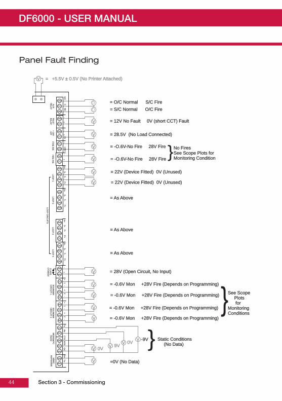
Panel Fault Finding
Section 3 - Commissioning
NO
NO
CN
CN
C
FAU
LTR
ELAY
FAU
LTR
ELAY
+ 24VO
/P+ 24V
O/P
FIRE
R/E
FIRE
R/E
FIRE
P/E
FIRE
P/E
CLA
SS
CH
AN
GE
CLA
SS
CH
AN
GE
SO
UN
DE
RC
IRC
UIT
1S
OU
ND
ER
CIR
CU
I T1
LOO
P1
LOO
P1
LOO
P3
LOO
P3
LOO
P2
LOO
P2
LOO
P4
LOO
P4
AU
XR
ELAY
AU
XR
ELAY
LOO
PC
IRC
UITS
LOO
PC
IRC
UITS
0V0VS
+S
+S
+S
+F-F-
F-F-F+F+
F+F+S
-S
-S
-S
--
+26V+26V
++
--
+-
+-
Rx
Rx
CTS
CTS
RTS
RTS
OV
OV
TxTxTx-Tx-
Tx+Tx+
S+
S+
F-F-F+F+
S-
S-
S+
S+
F-F-F+F+
S-
S-
+ 1 -+ 1 -
+ 2 -+ 2 -
SO
UN
DE
RC
IRC
UIT
2S
OU
ND
ER
CIR
CU
IT2
MO
DE
M/P
CR
s232M
OD
EM
/PC
Rs232
MIM
ICR
EP
EATE
RM
IMIC
RE
PE
ATER
+ 1 -+ 1 -
+ 2 -+ 2 -
V
V
V
V
V
V
V
V
V
V
V
V
V
V VV
V
�
�
= 28V (Open Circuit, No Input)= 28V (Open Circuit, No Input)
= -0.6V Mon +28V Fire (Depends on Programming)= -0.6V Mon +28V Fire (Depends on Programming)
= -0.6V Mon +28V Fire (Depends on Programming)= -0.6V Mon +28V Fire (Depends on Programming)
= -0.6V Mon +28V Fire (Depends on Programming)= -0.6V Mon +28V Fire (Depends on Programming)
= -0.6V Mon +28V Fire (Depends on Programming)= -0.6V Mon +28V Fire (Depends on Programming)
Static Conditions(No Data)
Static Conditions(No Data)
-9V-9V0V0V9V9V0V0V
=0V (No Data)=0V (No Data)
See ScopePlotsfor
MonitoringConditions
See ScopePlotsfor
MonitoringConditions
= O/C Normal S/C Fire= O/C Normal S/C Fire
= +5.5V ± 0.5V (No Printer Attached)= +5.5V ± 0.5V (No Printer Attached)
= S/C Normal O/C Fire= S/C Normal O/C Fire
= 12V No Fault 0V (short CCT) Fault= 12V No Fault 0V (short CCT) Fault
= 28.5V (No Load Connected)= 28.5V (No Load Connected)
= -O.6V-No Fire 28V Fire= -O.6V-No Fire 28V Fire No FiresSee Scope Plots forMonitoring Condition
No FiresSee Scope Plots forMonitoring Condition= -O.6V-No Fire 28V Fire= -O.6V-No Fire 28V Fire
= 22V (Device Fitted) 0V (Unused)= 22V (Device Fitted) 0V (Unused)
= 22V (Device Fitted) 0V (Unused)= 22V (Device Fitted) 0V (Unused)
= As Above= As Above
= As Above= As Above
= As Above= As Above
}
}}

DF6000 - USER MANUAL
45
Protocol Format
Normal Communications to Devices:With the command bits set for the 'Normal' command and the MSB of the 3 mode bits set at 0, thisshortened version of the normal communications to each device allows the analogue reply or status fromeach device to be read. This format of communication is generally used throughout all backgroundsupervision of the addressable loop.
Alarm Interrogate Command:This command is seen by all devices on the loop, so no address byte is required, and is periodically sentout during normal communications. This command allows any device experiencing an alarm condition torespond, with callpoints given the highest priority, reporting their address. This causes the control panelto break off from general background supervision of the loop and focus directly on the device in question.
Full Protocol Format:With the command bits set for the 'Normal' command and the MSB of the 3 mode bits set at 1, the longversion of the normal communications can be sent to any device. This would normally be done by thepanel following a response to the alarm Interrogate command, allowing the panel to check the deviceaddress, ID and confirm that the analogue reply, or status, is truly an alarm condition before actioning thepanel sounder outputs, for example.
Viewing the Voltage and Current waveforms at the panel:
Loop 1: Using a digital storage oscilloscope, connect one channel to R34 on the loop driver card; probe 0V clip to the 'in-board' side of the resistor. This will display the loop current. Connect theother channel to Loop 1, S+ terminal on the main mother board. DO NOT connect the 0v clip ofthis probe.
Loop 2: Using a digital storage oscilloscope, connect one channel to R36 on the loop driver card; probe 0V clip to the 'in-board' side of the resistor. This will display the loop current. Connect theother channel to Loop 2, S+ terminal on the main mother board. DO NOT connect the 0v clip ofthis probe
Section 3 - Commissioning
Byte 1 Byte 2 Byte 3
Parit
y
Command
2ms 300us
300us
Start
Panel to Device Device to Panel
Response8 bits
ID5 bits
Flags3 bits
A
Loop Current
24vtyp
7.5v0v
Mode
1.1 ms
Each Packet of Comms above must be separated by a gap of 20ms minimum where the line is held at 24v

DF6000 - USER MANUAL
46
PC Comissioning Software
Device Input Programming
Fire panel reports fire from device.Fault panel reports fault from device.Reset panel resets.Silence silence all currently active sounders.Pre-Alarm panel reports pre-alarm from device.Non-Latching device won't latch in alarm condition, used in conjunction with isolates.
Isolate Zone / AddressUser can define between zones or addresses to be isolated on activation of the device. The isolate listbutton enables the user to enter upto 8 unique zones or addresses.
If non-latching has been enabled, Isolated devices can be un-isolated as the triggered device returns tonormal operation. (a callpoint keyswitch is an example for this application).
Section 3 - Commissioning

DF6000 - USER MANUAL
47
PC Comissioning Software
Device Outputs
Delay ConfigurationThe output of a device when triggered can be delayed - based on a user defined value in minutes.This programming option is enabled when a value other than zero is entered inside the 'Delay' window.
MCP OverrideThis option is a manual intervention override, when enabled (check in box) the delay can be overriddenfrom any callpoint on the loop when triggered.
Section 3 - Commissioning

DF6000 - USER MANUAL
48
PC Comissioning Software
Panel Outputs
Dependency Type CEach panel output can be assigned a unique list of zones derived from the zones available on theloop, to activate this output, two unique zones from this list have to be in fire or alternatively anyzone outside this list will trigger the output also. When the 'Coincidence' box is checked - the'Allocate device' button allows the user to populate this list.
Section 3 - Commissioning

DF6000 - USER MANUAL
49
Section 4Panel Controls and Indicators
Section 4 - Panel Controls and Indicators

DF6000 - USER MANUAL
50
Panel Controls and Indicators
1. System LED’s2. Zonal LED’s3. Touch Screen Display4. Printer Access Door5. Slot for Optional Printer
Section 4 - Panel Controls and Indicators
Powe rON
Powe rON FIREFIRE General
FAUL TGeneralFAUL T
SystemDISABL ESystem
DISABL ESystemFAUL T
SystemFAUL T
SystemTEST
SystemTEST
ChargeFAUL T
ChargeFAUL T
BatteryFAUL TBatteryFAUL T
1 2 3 4 5 6 7 8 9
2121 2222 2323 2424
1010 1111 1212
1313 1414 1515 1616 1717 1818 1919 2020
2525 2626 2727 2828 2929 3030 3131 3232 3333 3434 3535 3636
3737 3838 3939 4040 4141 4242 4343 4444 4545 4646 4747 4848
4949 5050 5151 5252 5353 5454 5555 5656 5757 5858 5959 6060
6161 6262 6363 6464 6565 6666 6767 6868 6969 7070 7171 7272
7373 7474 7575 7676 7777 7878 7979 8080 8181 8282 8383 8484
8585 8686 8787 8888 8989 9090 9191 9292 9393 9494 9595 9696
ZonesZones
1 2 3 4
5
1 2 3 4 5 6 7 8 9 10 11
PowerON
PowerON FIREFIRE General
FAUL TGeneralFAUL T
ExtinguisherACTIV ATEDExtinguisherACTIV ATED
SystemDISABLESystem
DISABLESystemFAUL T
SystemFAUL T
SystemTEST
SystemTEST
PowerFAUL TPowerFAUL T
Zones
Disabl eDisabl eFaul tFaul t
DisableDisableFaul tFaul t
SounderSounder FREFRE DelayACTIVE
DelayACTIVE
LED Name Function Action1 Power On Shows Panel is On Check Indicator is Illuminated2 Fire Indicators Panel has Detected a Fire Impliment Fire Action Procedure3 General Fault Monitors Devices for Faults e.g. Smoke detectors/Sounders Report to System Supervisor4 System Fault Monitors Fire Panel for Faults Report Fault to Service Dept5 Power Fault Monitor Internal Battery Charger Report Fault to Service Dept6 Sounder Monitors Sounder Circuits/Indicates Disablement of this Output Report Fault to Service Dept7 System Disable Part of the System has been Disabled Report to System Supervisor8 System Test Supervisor/Engineer is Testing the System Check with System Supervisor9 FRE Monitors the FRE Circuit/Indicates Disablement of this Output Report Fault to Service Dept10 Extinguisher Activated Display Activatiion of Extinguishers (If Option Fitted) Check with System Supervisor11 Delay Active Delays on Outputs Active Check with System Supervisor

DF6000 - USER MANUAL
51
Panel Controls and Indicators
1. Log Book Storage2. Insert Supervisor Key Here3. Printer4. Paper Roll Storage
1. Optional Hinged Cover2. Scroll Up3. Mute Buzzer4. Scroll Down
Section 4 - Panel Controls and Indicators
PowerON
PowerON FIREFIRE General
FAUL TGeneralFAUL T
SystemDISABLESystem
DISABLESystemFAUL T
SystemFAUL T
SystemTEST
SystemTEST
ChargeFAUL T
ChargeFAUL T
BatteryFAUL TBatteryFAUL T
1 2 3 4 5 6 7 8 9
2121 2222 2323 2424
1010 1111 1212
1313 1414 1515 1616 1717 1818 1919 2020
2525 2626 2727 2828 2929 3030 3131 3232 3333 3434 3535 3636
3737 3838 3939 4040 4141 4242 4343 4444 4545 4646 4747 4848
4949 5050 5151 5252 5353 5454 5555 5656 5757 5858 5959 6060
6161 6262 6363 6464 6565 6666 6767 6868 6969 7070 7171 7272
7373 7474 7575 7676 7777 7878 7979 8080 8181 8282 8383 8484
8585 8686 8787 8888 8989 9090 9191 9292 9393 9494 9595 9696
ZonesZones
1
23 4
2
1
3
4
2

DF6000 - USER MANUAL
52
Touch Screen Display
The touch screen is a multi-function display consisting 320 x 240 dots featuring high intensitybacklighting. In normal operation, the display indicates as above with the backlighting off.
During an event on the system the display shows the FIRST EVENT and LAST EVENT plus other eventsas space allows.
The last 2 lines are normally used to display the total number of events, but they are also used forscrolling fire conditions, faults, pre alarms or disabled devices independently or for displaying a reducedmenu when in fire condition.
When an event occurs the touch screen backlighting comes on unless there is a mainspower supply fault.
Use the touch screen to scroll through all active events on the system by using the SCROLL UP andSCROLL DOWN buttons (available at access level 1). You can display the contents of the log and alsoview details of any fires, faults, pre-alarms,faults or disablements. When displaying the system menu onthe touch screen, the last 5 lines of the display are shown in reverse text.
Section 4 - Panel Controls and Indicators
SupervisorFRE Off
Faults0
Disabled/ Test
Tuesdaydd-mm-yyyy
16:25.25BST On
Fire0
PreAlarms 0
Systems HealthyXX Zones Acitve

DF6000 - USER MANUAL
53
Panel Operation
DF6000 is operated via a backlit touch screen. The default fire screen is shown below. From this screenall the panels functions can be operated. The first time you touch the screen the backlight will illuminatethe panel.
Pressing a field will highlight it and forward to the next screen as shown below.
Section 4 - Panel Controls and Indicators
SupervisorFRE Off
Faults0
Disabled/ Test
Tuesdaydd-mm-yyyy
16:25.25BST On
Fire0
PreAlarms 0
Systems HealthyXX Zones Acitve
SupervisorFRE Off
Faults0
Disabled/ Test
Tuesdaydd-mm-yyyy
16:25.25BST On
Fire1
PreAlarms 0
Systems Healthy10 Zones Acitve
SupervisorFRE Off
Faults0
Disabled/ Test
Tuesdaydd-mm-yyyy
16:25.25BST On
Fire1
PreAlarms 0
First Fire Meeting Room 1, Building 1, 1st floorLoop: 1, Zone: 2, Type: Optical (150)
Total Fires = 1 Print All Help
Touch the screen here to view details

DF6000 - USER MANUAL
54
Public (Access Level 1)
Public access level does not require an access code and allows anybody to review the functions outlinedbelow.
Section 4 - Panel Controls and Indicators
SupervisorFRE Off
Faults5
Disabled/ Test
Tuesdaydd-mm-yyyy
16:25.25BST On
Fire0
PreAlarms 0
Systems Healthy10 Zones Acitve
SupervisorFRE Off
Faults0
Disabled/ Test
Tuesdaydd-mm-yyyy
16:25.25BST On
Fire1
PreAlarms 0
First Fire 12:26:23 Device 1, Zone 1Lp: 1, Ad:1, Z:1, Opto/thermal, [69]
Total Fires = 1 Print All Help
Disabled/ Test
Pre Alarms 6
SupervisorFRE off
Fires0
Faults6
ShowZones
ShowI/O
Print All Help
001 Device 2, Zone 1Loop 1, Zone: 1, Type : Opto/thermal
002 Device 3, Zone 1Loop 1, Zone: 1, Type : Opto/thermal
003 Device 4, Zone 1Loop 1, Zone: 1, Type : Opto/thermal
004 Device 5, Zone 1Loop 1, Zone: 1, Type : Opto/thermal
ShowTest Zone
ShowAddresses
Disabled/ Test
PreAlarms 6
SupervisorFRE off
Fires0
Faults0
Print All Help
001 03-Jun-03 12:51 Warning! : Device 1Lp: 1, Ad: 1, Z: 1, Opto / Thermal [69]
002 03-Jun-03 12:51 Warning! : Device 2Lp: 1, Ad: 2, Z: 1, Opto / Thermal [69]
003 03-Jun-03 12:51 Warning! : Device 3Lp: 1, Ad: 3, Z: 1, Opto / Thermal [69]
004 03-Jun-03 12:51 Warning! : Device 4Lp: 1, Ad: 4, Z: 1, Opto / Thermal [69]
005 03-Jun-03 12:51 Warning! : Device 5Lp: 1, Ad: 5, Z: 1, Opto / Thermal [69]
Disabled/ Test
PreAlarms 6
SupervisorFRE off
Fires0
Faults5
Print All Help
001 03-Jun-03 12:51 Fault! : Device 1Lp: 1, Ad: 1, Z: 1, Opto / Thermal [0]
002 03-Jun-03 12:51 Fault! : Device 2Lp: 1, Ad: 2, Z: 1, Opto / Thermal [69]
003 03-Jun-03 12:51 Fault! : Device 3Lp: 1, Ad: 3, Z: 1, Opto / Thermal [69]
004 03-Jun-03 12:51 Fault! : Device 4Lp: 1, Ad: 4, Z: 1, Opto / Thermal [69]
005 03-Jun-03 12:51 Fault! : Device 5Lp: 1, Ad: 5, Z: 1, Opto / Thermal [69]
Public access level

DF6000 - USER MANUAL
55
Evacuate (Access Level 2)
To activate the touch screen, touch the top left corner of the screen until the screen illuminates. To enterthe supervisor mode touch the supervisor button and enter the passcode.
Enter the Supervisor Mode Passcode and select “Evacuate” on the menu at the top of the screen.
Select “Yes” to evacuate the building.
Section 4 - Panel Controls and Indicators
ResetSilenceAlarms
SupervisorFRE off
MuteBuzzer
Pre-alarm = Some smoke / heat but below fire thresholdthese warnings will appear and disappear
Evacuate
View FiresAC = 0 View Pre
Alarms
ViewDisabled
ViewFaults
Others
This will activate ALL soundersand activate all panel relaysDo you wish to continue?
SupervisorFRE Off
Yes No

DF6000 - USER MANUAL
56
Silence Alarms
To activate the touch screen, touch the top left corner of the screen until the screen illuminates. To enterthe supervisor mode touch the supervisor button and enter the passcode.
Enter the Supervisor Mode Passcode and select “Silence Alarms” button as the top of
Select “yes” to silence Alarm.
Section 4 - Panel Controls and Indicators
ResetSupervisorFRE off
MuteBuzzer
View FiresAC = 0 View Pre
Alarms ViewDisabled
ViewFaults
Others
Evacuate
I/O Zone: 0
SilenceAlarms
Address: 0
Touch button to view list
This will silence ALL soundersDo you wish to continue?
SupervisorFRE Off
Yes No

DF6000 - USER MANUAL
57
Mute Buzzer
To activate the touch screen, touch the top left corner of the screen until the screen illuminates. To enterthe supervisor mode touch the supervisor button and enter the passcode.
Enter the Supervisor Mode and Select “Mute Buzzer” from the Top Menu
Reset
Enter the Supervisor Mode and Select “Reset” from the top Menu. Select “Yes” to reset the panel.
Section 4 - Panel Controls and Indicators
ResetSilenceAlarms
SupervisorFRE off
Evacuate
View FiresAC =19 View Pre
Alarms ViewDisabled View
Faults Others
MuteBuzzer
Lamp Test
Weekly Test
Veiw Log
Enable / Disable Send Log to PC
Check Config.
Send Analogue Value to PC
SilenceAlarms
SupervisorFRE off
Evacuate
View FiresAC =19 View Pre
Alarms ViewDisabled View
Faults
Others
001 14:22:49 Mains Failure
MuteBuzzer Reset
Faults = Short circuits, broken detectors etc.To remove faults from this list:1) Fix Fault2) Reset Panel
The panel will resetDo you wish to continue?
SupervisorFRE Off
Yes No

DF6000 - USER MANUAL
58
Pre-Alarms
Enter the Supervisor Mode and Select “Pre-Alarms” tab.
A pre-alarm is shown when a detector appears to register heat or smoke but in a quantity that isinsufficient to warrant an alarm. Pre-alarm may indicate a build up of dirt in a smoke detector which canbe interpreted by the detector as smoke presence.
Disabled Devices
Enter the Supervisor mode and Select the “Disabled” tab.
The individual buttons show which devices and the number of devices which have been disabled. Pressone of the buttons to display detailed information for a particular category
Section 4 - Panel Controls and Indicators
ResetSilenceAlarms
SupervisorFRE off
MuteBuzzer
Pre-alarm = Some smoke / heat but below fire thresholdthese warnings will appear and disappear
Evacuate
View FiresAC = 0 View Pre
Alarms
ViewDisabled
ViewFaults
Others
ResetSupervisorFRE off
MuteBuzzerEvacuate
I/O Zone: 0
SilenceAlarms
Address: 0
Touch button to view list
View FiresAC = 0 View Pre
Alarms ViewDisabled
ViewFaults
Others

DF6000 - USER MANUAL
59
Faults
Enter Supervisor Mode Passcode and select “Faults” tab.
Enable/Disable (Others Menu)
To activate the touch screen, touch the top left corner of the screen until the screen illuminates. To enterthe supervisor mode touch the supervisor button and enter the passcode
Enter the Supervisor Mode passcode and select the “Others” tab.
Section 4 - Panel Controls and Indicators
SilenceAlarms
SupervisorFRE off
Evacuate
FiresAC = 0 View Pre
Alarms ViewDisabled View
Faults
Others
MuteBuzzer Reset
Pre-alarm = Some smoke / heat but below fire thresholdThese warnings will appear and disappear
ResetSilenceAlarms
SupervisorFRE off
Evacuate
FiresAC = 0 View Pre
Alarms ViewDisabled View
Faults Others
Lamp Test
Weekly Test
Veiw Log
MuteBuzzer
Enable / Disable Send Log to PC
Check Config.
Send Analogue Value to PC

DF6000 - USER MANUAL
60
Enable/Disable (Others Menu) Cont.
The Enable/Disable feature allows the operator to disable part or a whole system by the sub menusshown on the left.
Section 4 - Panel Controls and Indicators
ResetSupervisorFRE Off
Evacuate MuteBuzzer
Network Enable / Disable
Enable / Disable Zone
Enable / Disable I/O
Enable All
Enable / Disable Address
SilenceAlarms
Exit
ResetSupervisorFRE Off
MuteBuzzer
Evacuate SilenceAlarms
Exit
Enable
Enable
Disable
Disable
Zone 001 Zone 1
Zone 002 Zone 2
Zone 003 Zone 3
Zone 004 Zone 4
Touch “Enabled” button to DisableTouch “Disabled” button to Enalbe
SupervisorFRE Off
Enable all devices?
Do you want to continue?
Yes No
ResetSupervisorFRE Off
MuteBuzzer
ShowDetectors
ShowAlarms
ShowI/O Units
001 Device 1, Zone 1Loop 1, Zone 1, Type: Optical / Thermal
002 Device 2, Zone 1Loop 1, Zone 1, Type: Optical / Thermal
003 Device 3, Zone 1Loop 1, Zone 1, Type: Optical / Thermal
004 Device 4, Zone 1Loop 1, Zone 1, Type: Optical / Thermal
ShowAll
Evacuate SilenceAlarms
Exit
005 Device 5, Zone 1Loop 1, Zone 1, Type: Optical / Thermal
Enable
Enable
Disable
Disable
Disable
EvacuateSupervisor
FRE OffMute
Buzzer Reset
Fire Routing: Enabled
Fault Realy: Enabled
Aux Realy: Enabled
Delayed: Enabled
Fire Protection: Enabled
Fire Relay: Enabled
SilenceAlarms
Exit

DF6000 - USER MANUAL
61
To activate the touch screen, touch the top left corner of the screen until the screen illuminates. To enterthe supervisor mode touch the supervisor button and enter the passcode.
Enter the Supervisor Mode and Select the “Others” Tab. Press “Print”
Select the Information You wish to Print from the Buttons Listed.
Section 4 - Panel Controls and Indicators
ResetSilenceAlarms
SupervisorFRE off
Evacuate
FiresAC = 19 View Pre
Alarms ViewDisabled View
Faults Others
Lamp Test
Weekly Test
Veiw Log
MuteBuzzer
Enable / Disable Send Log to PC
Check Config.
Send Analogue Value to PC
EvacuateServiceFRE off
MuteBuzzer Reset
Print All Log Records
Print Test Log
Print Current Files
Print Current Faults
Print Disablement
Print last 10 Log Records
Print Fire Log
SilenceAlarm
Print Fault Log
Exit

DF6000 - USER MANUAL
62
Lamp Test
To activate the touch screen, touch the top left corner of the screen until the screen illuminates. To enterthe supervisor mode touch the supervisor button and enter the passcode.
Enter the Supervisor Mode and Select the “Others” Tab. Press “Lamp Test”
Section 4 - Panel Controls and Indicators
ResetSilenceAlarms
SupervisorFRE off
Evacuate
FiresAC = 19 View Pre
Alarms ViewDisabled View
Faults Others
Lamp Test
Weekly Test
Veiw Log
MuteBuzzer
Enable / Disable Send Log to PC
Check Config.
Send Analogue Value to PC
Lamp Test
LED’s will light innumerical order
SupervisorFRE Off
Yes No

DF6000 - USER MANUAL
63
Weekly Test
To activate the touch screen, touch the top left corner of the screen until the screen illuminates. To enterthe supervisor mode touch the supervisor button and enter the passcode. Select the others tab asshown below. Press Weekly test.
Weekly test is now in progress.
The panel will automatically return to the system healthy screen once the weekly test has beencompleted.
Section 4 - Panel Controls and Indicators
ResetSilenceAlarms
SupervisorFRE off
Evacuate
FiresAC = 19 View Pre
Alarms ViewDisabled View
Faults Others
Lamp Test
Weekly Test
Veiw Log
MuteBuzzer
Enable / Disable Send Log to PC
Check Config.
Send Analogue Value to PC
Weekly TestDo you want to continue?
SupervisorFRE Off
Yes No
* Features outside EN54 spec
Weekly TestAwaiting alarm signal
Will rest after 4 minutes
Cancel

DF6000 - USER MANUAL
64
Viewing Events
To activate the touch screen, touch the top left corner of the screen until the screen illuminates. To enterthe supervisor mode touch the supervisor button and enter the passcode.
Enter the Supervisor Mode Passcode. Select the “Others” tab and press View Log.
Use the scroll bar to view the list of upto 1000 events.
The DF6000 event log stores up to 1000 events including, fires, faults, resets and address changes.Once the maximum 1000 events has been reached DF6000 will automatically overwrite the oldest eventevery time a new event is stored. The event log can only be reset by an approved service engineer.
Section 4 - Panel Controls and Indicators
ResetSilenceAlarms
SupervisorFRE off
Evacuate
FiresAC = 19 View Pre
Alarms ViewDisabled View
Faults Others
Lamp Test
Weekly Test
Veiw Log
MuteBuzzer
Enable / Disable Send Log to PC
Check Config.
Send Analogue Value to PC
ResetSilenceAlarms
SupervisorFRE off
Evacuate MuteBuzzer
Newest Oldest Exit
ShowFires
ShowFaults
ShowTests
001 Monday 13-Jan-2004 08:34:12Hard Reset
002 FIRE! Lobby, [Optional] (Ana=150)Building 1, Ground flour, Panel 1, Loop1, device 1
003 Monday 06-Nov-2000 11:22:12Soft Reset
004 Monday 13-Nov-2001 11:22:12 FaultPanel 1, Loop1, device 1
005 Monday 18-Feb-2001 22:20:18Mains or battery failure
ShowAll
Events can be sortedby selecting from thesort option menu.
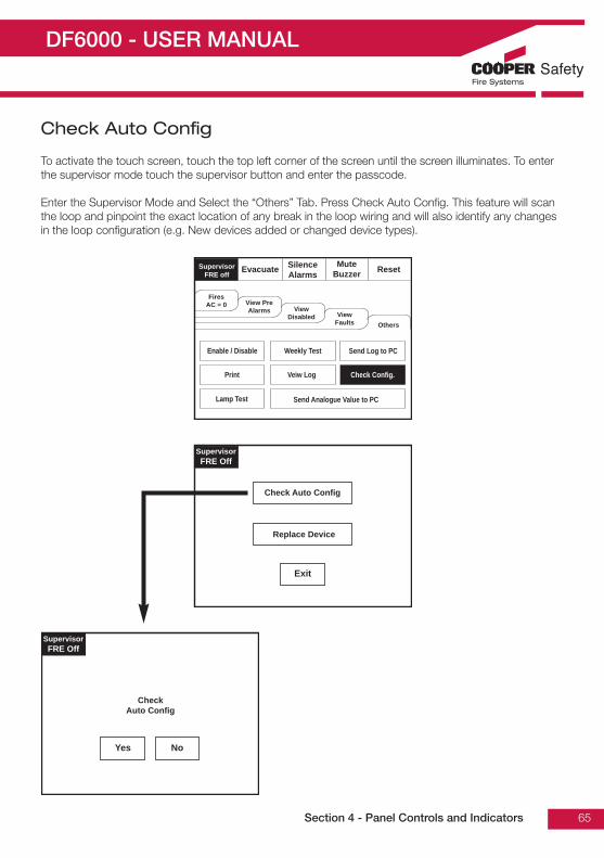
DF6000 - USER MANUAL
65
Check Auto Config
To activate the touch screen, touch the top left corner of the screen until the screen illuminates. To enterthe supervisor mode touch the supervisor button and enter the passcode.
Enter the Supervisor Mode and Select the “Others” Tab. Press Check Auto Config. This feature will scanthe loop and pinpoint the exact location of any break in the loop wiring and will also identify any changesin the loop configuration (e.g. New devices added or changed device types).
Section 4 - Panel Controls and Indicators
ResetSilenceAlarms
SupervisorFRE off
Evacuate
FiresAC = 0 View Pre
Alarms ViewDisabled View
Faults Others
Lamp Test
Weekly Test
Veiw Log
MuteBuzzer
Enable / Disable Send Log to PC
Check Config.
Send Analogue Value to PC
SupervisorFRE Off
Exit
Replace Device
Check Auto Config
CheckAuto Config
SupervisorFRE Off
Yes No

DF6000 - USER MANUAL
66
Replace Device
Replace device enables an existing device to be replaced with a new device without losing the existingtext and sounder programming. Replace a single device then use use the replace device menu to allocatean existing address to the new device
Section 4 - Panel Controls and Indicators
ResetSilenceAlarms
SupervisorFRE off
Evacuate
FiresAC = 0 View Pre
Alarms ViewDisabled View
Faults Others
Lamp Test
Weekly Test
Veiw Log
MuteBuzzer
Enable / Disable Send Log to PC
Check Config.
Send Analogue Value to PC
SupervisorFRE Off
Exit
Replace Device
Check Auto Config
SupervisorFRE off
Select a Loop
Exit
Loop 1
Loop 2
SupervisorFRE off
Enter Loop 1 Address
Exit
1 2 3054 6
7 8 9Del
OK

DF6000 - USER MANUAL
67
Test Device (Access Level 3)
To activate the touch screen, touch the top left corner of the screen until the screen illuminates. To enterthe service mode touch the supervisor button and enter engineer passcode.
Section 4 - Panel Controls and Indicators
ResetServiceFRE off
Exit MuteBuzzer
Commission
Configure
Test
Enable/Disable Address
ResetServiceFRE off
Exit MuteBuzzer
Test Device
Test Zone
Sounder Level Test Mode
Globle Flashing LED on/ff
One Walk Walk Test
ResetServiceFRE off
Exit
ShowDetectors
ShowAlarms
ShowRelay
001 Lobby, Building 1, 1st FloorLoop 1, Zone 2, Type: Optical
002 Main Reception, Building 1, 1st FloorLoop 1, Zone 2, Type: Optical
003 Storage / archive, Building 1, 1st FloorLoop 1, Zone 2, Type: Optical
004 Meeting Room 1, Building 1, 1st FloorLoop 1, Zone 2, Type: Optical
ShowAll
Touch row to test
Test Devises
Loop 1, Address 1
Yes No
Enter the Servicemode. Select “Test”.
Select the “Test Device” button.
Touch row to select device to test.

DF6000 - USER MANUAL
68
Test Zone
To activate the touch screen, touch the top left corner of the screen until the screen illuminates. To enterthe supervisor mode touch the supervisor button and enter the service passcode.
Enter the Service Mode, Select “Test” and on the Screen Shown Below Press “Test Zone”
Section 4 - Panel Controls and Indicators
ResetServiceFRE off
Exit MuteBuzzer
Test Device
Test Zone
Sounder Level Test Mode
Globle Flashing LED on/ff
One Walk Walk Test
ResetServiceFRE off
Exit
Touch “_” Button to place a zone into test modeTouch “_” Button to remove a zone into test mode
Zone 001 Building 1, Ground
Zone 002 Building 1, 1st Floor
Zone 003 Building 1, 2nd Floor
Zone 004 packing & Stores
Zone 005 Building 2, Basement
Test
_
_
_
_

DF6000 - USER MANUAL
69
Sounder Level Test Mode
Enter the Service Mode and Select Test. From the Test Menu Select “Sounder Level Test Mode”
Section 4 - Panel Controls and Indicators
Sound Level Test Mode
All sounders will now pulse15 seconds on, 30 seconds off
Touch “Stop” button to stop test
Stop
Sound Level Test Mode
Do you want to continue?
Yes No
ResetServiceFRE off
Exit MuteBuzzer
Commission
Configure
Test
Enable/Disable Address
ResetServiceFRE off
Exit MuteBuzzer
Test Device
Test Zone
Sounder Level Test Mode
Globle Flashing LED on/ff
One Walk Walk Test

DF6000 - USER MANUAL
70
Global Flashing LED On/Off
To activate the touch screen, touch the top left corner of the screen until the screen illuminates. To enterthe supervisor mode touch the supervisor button and enter the service passcode.
Enter the Service Mode and Select Test.
Section 4 - Panel Controls and Indicators
If global LED flashing isset to on, all deviceLED’s will pulseintermittently toconfirm correctcommunication.
Select “Global FlashingLED On/Off” from theTest Menu Screen.
Global Flashing LED’s
Flashing Off
ResetServiceFRE off
Exit MuteBuzzer
Test Device
Test Zone
Sounder Level Test Mode
Globle Flashing LED on/ff
One Walk Walk Test
ResetServiceFRE off
Exit MuteBuzzer
Commission
Configure
Test
Enable/Disable Address

DF6000 - USER MANUAL
71
One Man Walk Test
To activate the touch screen, touch the top left corner of the screen until the screen illuminates. To enterthe supervisor mode touch the supervisor button and enter the service passcode.
Enter the Service Mode and Select Test.
Section 4 - Panel Controls and Indicators
Select “One ManWalk Test” from theTest Menu Screen.
ResetServiceFRE off
Exit MuteBuzzer
Commission
Configure
Test
Enable/Disable Address
ResetServiceFRE off
Exit MuteBuzzer
Test Device
Test Zone
Sounder Level Test Mode
Globle Flashing LED on/ff
One Walk Walk Test
One Man Walk test
Do you want to continue?
Yes No
* Features outside EN54 spec
One Man Walk Test
Awaiting Alarm Signal
Stop

DF6000 - USER MANUAL
72
Commission: Load CDR from Laptop
To activate the touch screen, touch the top left corner of the screen until the screen illuminates. To enterthe supervisor mode touch the supervisor button and enter the service passcode.
Enter the Service Mode and Select Commission.
Section 4 - Panel Controls and Indicators
Select “Load CDRfrom Laptop” from theCommission Menu”
After pressing “Yes”click commission onthe PC downloadsoftware.
Important:Do not clickcommission beforepressing “Yes” on the“Load CDR” screen.
Load CDR from Laptop
This will erase the current CDRDo you want to continue?
Yes No
ServiceFRE Off Exit Mute
Buzzer Reset
Load CDR from Laptop
Dowload CDR to Laptop
Auto Learn
Erase Log
Systems Detail
Load Logo From PC
Printer Settings
Change Panel Number
Number of Panelin Network
Screen Cover
Analogue Level
Italian Mode
ResetServiceFRE off
Exit MuteBuzzer
Commission
Configure
Test
Enable/Disable Address

DF6000 - USER MANUAL
73
Commission: Download CDR to Laptop
To activate the touch screen, touch the top left corner of the screen until the screen illuminates. To enterthe supervisor mode touch the supervisor button and enter the service passcode.
Enter the Service Mode and Select Commission.
Section 4 - Panel Controls and Indicators
Select “Download CDRfrom Laptop” from theCommission MenuScreen.
Download CDR to Laptop
Start PC Program
Press “OK” to continueOr “Cancel” to Exit
Ok Cancel
ServiceFRE Off Exit Mute
Buzzer Reset
Load CDR from Laptop
Dowload CDR to Laptop
Auto Learn
Erase Log
Systems Detail
Load Logo From PC
Printer Settings
Change Panel Number
Number of Panelin Network
Screen Cover
Analogue Level
Italian Mode
ResetServiceFRE off
Exit MuteBuzzer
Commission
Configure
Test
Enable/Disable Address

DF6000 - USER MANUAL
74
Commission: Auto Learn
To activate the touch screen, touch the top left corner of the screen until the screen illuminates. To enterthe supervisor mode touch the supervisor button and enter the service passcode.
Enter the Service Mode and Select Commission.
Section 4 - Panel Controls and Indicators
Select “Auto Learn”from the ConfigureMenu Screen.
Important:Activating autolearnwill erase all existingprogramming, textand configurationdata.
ServiceFRE off
Exit
No
Pre- Addressed Auto Learn
Auto Learn
Do you want to continue?
Yes - Autolearn All Loops
Load CDR from Laptop
Dowload CDR to Laptop
Auto Learn
Erase Log
Systems Detail
Load Logo From PC
Printer Settings
Change Panel Number
Number of Panelin Network
Screen Cover
Analogue Level
Italian Mode
ResetServiceFRE off
Exit MuteBuzzer
Commission
Configure
Test
Enable/Disable Address

DF6000 - USER MANUAL
75
Erase Log
To activate the touch screen, touch the top left corner of the screen until the screen illuminates. To enterthe supervisor mode touch the supervisor button and enter the service passcode.
Enter the Service Mode and Select Commission.
Section 4 - Panel Controls and Indicators
Select “Erase Logand Reset” from theConfigure MenuScreen.
This will delete all log entries
Do you want to continue?
Yes No
ServiceFRE Off Exit Mute
Buzzer Reset
Load CDR from Laptop
Dowload CDR to Laptop
Auto Learn
Erase Log
Systems Detail
Load Logo From PC
Printer Settings
Change Panel Number
Number of Panelin Network
Screen Cover
Analogue Level
Italian Mode
ResetServiceFRE off
Exit MuteBuzzer
Commission
Configure
Test
Enable/Disable Address

DF6000 - USER MANUAL
76
System Details
To activate the touch screen, touch the top left corner of the screen until the screen illuminates. To enterthe supervisor mode touch the supervisor button and enter the service passcode.
Enter the Service Mode and Select Commission, then Press “System Details”.
Section 4 - Panel Controls and Indicators
ServiceFRE Off Print Reset
Loop 1 Loop 2 Loop 3 Loop 4
SCU 0 0 0 0Voice Annunciator 13 14 0 0Repeater 0 0 0 0ZMU / {SUM 0 0 0 0Beam Detector 0 0 0 0Technical Timer 2 1 0 0Access Control 0 0 0 0Emerg.Light.Module 0 0 0 0Carbon Monoxide 0 0 0 0
Exit
Page 1 Page 2 Page 3 Page 4 Page 5
ServiceFRE Off Print Reset
Program V3.02.01Program Data 22/01.08CDR V0.5CDR Checksum 0xF7D95ELoop Controller 1 V2.1.4Loop Controller 2 V0.0.0Panel Number 0Total Panels 1Total Addresses 13Total Zones 4
Exit
Page 2 Page 3Page 1 Page 4 Page 5
ResetServiceFRE off
Exit MuteBuzzer
Commission
Configure
Test
Enable/Disable Address
ServiceFRE Off Exit Mute
Buzzer Reset
Load CDR from Laptop
Dowload CDR to Laptop
Auto Learn
Erase Log and Reset
Systems Detail
Load Logo From PC
Printer Settings
Change Panel Number
Number of Panelin Network
Screen Cover
Analogue Level
Italian Mode
ServiceFRE Off Print Reset
Loop 1 Loop 2 Loop 3 Loop 4
Optical 0 0 0 0Ionisation 13 14 0 0Thermal A1R 0 0 0 0Opto / Thermal 0 0 0 0Thermal BS 0 0 0 0Thermal CS 2 1 0 0Alarm 0 0 0 0I / O Units 0 0 0 0
Exit
Page 1 Page 3Page 2 Page 4 Page 5

DF6000 - USER MANUAL
77
Analogue Level
To activate the touch screen, touch the top left corner of the screen until the screen illuminates. To enterthe supervisor mode touch the supervisor button and enter the service passcode.
Enter the Service Mode and Select Commission then press “Analogue Levels”.
Section 4 - Panel Controls and Indicators
14 5 67 8 9
ok 0
2 3..............................
Cancel
Enter Address
Loop 1
Loop 2
Loop 4
Loop 3
0 - 13
0 - 0
0 - 0
0 - 0
ResetGotoServiceFRE Off Exit
ShowAll
ShowDetectors
ShowOptical
ShowIonisation
001 Device 1, Zone 1Loop: 1, Zone 1, Type: Opto / Thermal
002 Device 2, Zone 1Loop: 1, Zone 1, Type: Opto / Thermal
003 Device 3, Zone 1Loop: 1, Zone 1, Type: Opto / Thermal
004 Device 4, Zone 1Loop: 1, Zone 1, Type: Opto / Thermal
005 Device 5, Zone 1Loop: 1, Zone 1, Type: Opto / Thermal
ShowThermal
ResetServiceFRE off
Exit MuteBuzzer
Commission
Configure
Test
Enable/Disable Address
ServiceFRE Off Exit Mute
Buzzer Reset
Load CDR from Laptop
Dowload CDR to Laptop
Auto Learn
Erase Log and Reset
Systems Detail
Load Logo From PC
Printer Settings
Change Panel Number
Number of Panelin Network
Screen Cover
Analogue Level
Italian Mode
Note:Go to command canbe used to jump to aspecific address

DF6000 - USER MANUAL
78
Printer Settings
To activate the touch screen, touch the top left corner of the screen until the screen illuminates. To enterthe supervisor mode touch the supervisor button and enter the service passcode.
Enter the Service Mode and Select Commission then press “Printer settings”.
Section 4 - Panel Controls and Indicators
ServiceFRE Off Exit Reset
Auto
Request
ServiceFRE Off Exit Mute
Buzzer Reset
Load CDR from Laptop
Dowload CDR to Laptop
Auto Learn
Erase Log and Reset
Systems Detail
Load Logo From PC
Printer Settings
Change Panel Number
Number of Panelin Network
Screen Cover
Analogue Level
Italian Mode
ResetServiceFRE off
Exit MuteBuzzer
Commission
Configure
Test
Enable/Disable Address
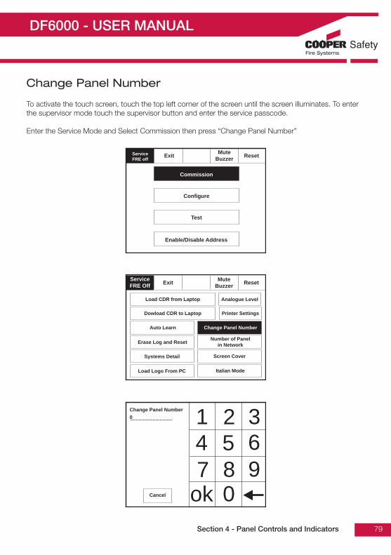
DF6000 - USER MANUAL
79
Change Panel Number
To activate the touch screen, touch the top left corner of the screen until the screen illuminates. To enterthe supervisor mode touch the supervisor button and enter the service passcode.
Enter the Service Mode and Select Commission then press “Change Panel Number”
Section 4 - Panel Controls and Indicators
14 5 67 8 9
ok 0
2 3..............................
Cancel
Change Panel Number0
ServiceFRE Off Exit Mute
Buzzer Reset
Load CDR from Laptop
Dowload CDR to Laptop
Auto Learn
Erase Log and Reset
Systems Detail
Load Logo From PC
Printer Settings
Change Panel Number
Number of Panelin Network
Screen Cover
Analogue Level
Italian Mode
ResetServiceFRE off
Exit MuteBuzzer
Commission
Configure
Test
Enable/Disable Address

DF6000 - USER MANUAL
80
Number of Panels in Network
To activate the touch screen, touch the top left corner of the screen until the screen illuminates. To enterthe supervisor mode touch the supervisor button and enter the service passcode.
Enter the Service Mode and Select Commission then press “Number of Panels in Network”
Section 4 - Panel Controls and Indicators
14 5 67 8 9
ok 0
2 3..............................
Cancel
Number of PanelsIn Network1
ServiceFRE Off Exit Mute
Buzzer Reset
Load CDR from Laptop
Dowload CDR to Laptop
Auto Learn
Erase Log and Reset
Systems Detail
Load Logo From PC
Printer Settings
Change Panel Number
Number of Panelin Network
Screen Cover
Analogue Level
Italian Mode
ResetServiceFRE off
Exit MuteBuzzer
Commission
Configure
Test
Enable/Disable Address
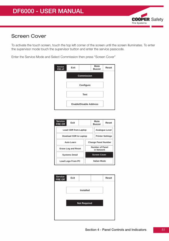
DF6000 - USER MANUAL
81
Screen Cover
To activate the touch screen, touch the top left corner of the screen until the screen illuminates. To enterthe supervisor mode touch the supervisor button and enter the service passcode.
Enter the Service Mode and Select Commission then press “Screen Cover”
Section 4 - Panel Controls and Indicators
ServiceFRE Off Exit Reset
Installed
Not Required
ServiceFRE Off Exit Mute
Buzzer Reset
Load CDR from Laptop
Dowload CDR to Laptop
Auto Learn
Erase Log and Reset
Systems Detail
Load Logo From PC
Printer Settings
Change Panel Number
Number of Panelin Network
Screen Cover
Analogue Level
Italian Mode
ResetServiceFRE off
Exit MuteBuzzer
Commission
Configure
Test
Enable/Disable Address

DF6000 - USER MANUAL
82
Programming I/O and Sounders
To activate the touch screen, touch the top left corner of the screen until the screen illuminates. To enterthe supervisor mode touch the supervisor button and enter the service passcode.
Enter the Service Mode and Select Configure.
Section 4 - Panel Controls and Indicators
Select “ProgrammingI/O and Sounders””from the ConfigureMenu Screen.
Press panel outputs -
Note:InterfaceInputs/InterfaceOutputs are onlyused in certainexport markets
ExitServiceFRE Off
MuteBuzzer Reset
T1/T2
FRE Double Knock OverrideHMO
Auxiliary Board
Panel Outputs
Alarm Verification Feature
Sounder Tone
ExitServiceFRE Off
MuteBuzzer Reset
Programming I/Oand Sounders
Day / Night
Network
Change Passcode
Configure Zones
Change Text
Change Date/Time
Add/Delete
Configure Heat Detectors
Language
ResetServiceFRE off
Exit MuteBuzzer
Commission
Configure
Test
Enable/Disable Address

DF6000 - USER MANUAL
83
Sound Settings
Touch sound settings.
Selections from the screens below will become the global settings for all loop sounders.
Section 4 - Panel Controls and Indicators
ServiceFRE Off
Exit
Sound Settings
Reset
ServiceFRE Off
Exit
Volume
Sound
Reset ServiceFRE Off
Exit
Low
Medium
High
Reset
VolumeThis will efffect all sounders
ServiceFRE Off
Exit
Volume
Sound
Reset ServiceFRE Off
Exit
Slow Loop
Two Tone
Continuous
Reset
VolumeThis will efffect all sounders

DF6000 - USER MANUAL
84
Change Date/Time
Enter the Service Mode and Select Configure. Select Change Date/Time.
Set the Time Using the Buttons Shown Below.
Section 4 - Panel Controls and Indicators
ServiceFRE Off OK Reset
+ 1Hour
Cancel
- 1Hour
- 10Minutes
+ 10Minutes
+ 1Minute
- 1Minute
+ 1Day
- 1Day
- 10Month
+ 10Month
+ 1Year
- 1Year
Current Time:
BST On
Current Date:
Wednesdaydd-mmm-yyyy
10:10:04
ExitServiceFRE Off
MuteBuzzer Reset
Programming I/Oand Sounders
Network
Change Passcode
Configure Zones
Change Text
Change Date/Time
Add/Delete
Configure Heat Detectors
Language

DF6000 - USER MANUAL
85
Change Address Text
Enter the Service Mode and Select Configure. Select “Change Text”
Press “Change Address Text”
Section 4 - Panel Controls and Indicators
ExitServiceFRE Off
MuteBuzzer Reset
Programming I/Oand Sounders
Network
Change Passcode
Configure Zones
Change Text
Change Date/Time
Add/Delete
Configure Heat Detectors
Language
ServiceFRE off
Exit MuteBuzzer
Change Address Text
Change Zone Text
Change Panel
Reset
ResetServiceFRE Off Exit
ShowDetectors
ShowAlarms
ShowI/O Units
001 Device 1, Zone 1Loop: 1, Zone 1, Type: Opto / Thermal
002 Device 2, Zone 1Loop: 1, Zone 1, Type: Opto / Thermal
003 Device 3, Zone 1Loop: 1, Zone 1, Type: Opto / Thermal
004 Device 4, Zone 1Loop: 1, Zone 1, Type: Opto / Thermal
005 Device 5, Zone 1Loop: 1, Zone 1, Type: Opto / Thermal
ShowAll
1
Q
A
Z X C V B
S D F G
CAPS
OTHER
...........................................................................
SPACE
W E R T Y
2 3 4 5 6
U I O P
7 8 9 0
N M , .
H J K L
OK CANCEL
Name for address 1
Address 1
Select the Address you wish to change and edit using the keyboard

DF6000 - USER MANUAL
86
Change Zone Text
Enter the Service Mode and Select Configure. Select “Change Text”
Section 4 - Panel Controls and Indicators
ExitServiceFRE Off
MuteBuzzer Reset
Programming I/Oand Sounders
Network
Change Passcode
Configure Zones
Change Text
Change Date/Time
Add/Delete
Configure Heat Detectors
Language
ServiceFRE off
Exit MuteBuzzer
Change Address Text
Change Zone Text
Change Panel
Reset
ResetSupervisorFRE Off
Exit
Zone 001 Zone 1
Zone 002 Zone 2
Zone 003 Zone 3
Zone 004 Zone 4
1
Q
A
Z X C V B
S D F G
CAPS
OTHER
..........................................................
SPACE
W E R T Y
2 3 4 5 6
U I O P
7 8 9 0
N M , .
H J K L
OK CANCEL
Enter the name for zone 2
Zone 2
Select the Address you wish to change and edit using the keyboard
Press “Change Zone Text”

DF6000 - USER MANUAL
87
Change Panel Text
Enter the Service Mode and Select Configure. Select “Change Text”
Section 4 - Panel Controls and Indicators
Press “Change Panel Text”
1
Q
A
Z X C V B
S D F G
CAPS
OTHER
..........................................................
SPACE
W E R T Y
2 3 4 5 6
U I O P
7 8 9 0
N M , .
H J K L
OK CANCEL
Correct Panel Text
DF6000
ServiceFRE off
Exit
Change Address Text
Change Zone Text
Change Panel
Reset
ExitServiceFRE Off
MuteBuzzer Reset
Programming I/Oand Sounders
Network
Change Passcode
Configure Zones
Change Text
Change Date/Time
Add/Delete
Configure Heat Detectors
Language

DF6000 - USER MANUAL
88
Configure Zones
Enter the Service Mode and Select Configure. Select “Configure Zones”
Section 4 - Panel Controls and Indicators
Select Zone into whichdevice will be added
Touch the dash tomove the device intothe selected zone.
ResetServiceFRE Off Exit
ShowDetectors
ShowAlarms
ShowI/O Units
001 Device 1, Zone 1Loop: 1, Zone 1, Type: Opto / Thermal
002 Device 2, Zone 1Loop: 1, Zone 1, Type: Opto / Thermal
003 Device 3, Zone 1Loop: 1, Zone 1, Type: Opto / Thermal
004 Device 4, Zone 2Loop: 1, Zone 2, Type: Opto / Thermal
005 Device 5, Zone 2Loop: 1, Zone 2, Type: Opto / Thermal
ShowAll
ShowSelected
Goto
In Zone
In Zone
In Zone
_
_
ResetServiceFRE Off
Touch row to configure
Zone 001 Zone 1
Zone 002 Zone 2
Zone 003 Zone 3
Zone 004 Zone 4
Exit
ExitServiceFRE Off
MuteBuzzer Reset
Programming I/Oand Sounders
Network
Change Passcode
Configure Zones
Change Text
Change Date/Time
Add/Delete
Configure Heat Detectors
Language

DF6000 - USER MANUAL
89
Change User Code
Enter the Service Mode and Select Configure. Select “Change User Code”
Section 4 - Panel Controls and Indicators
ExitServiceFRE Off Reset
Programming I/Oand Sounders
Network
Change Passcode
Configure Zones
Change Text
Change Date/Time
Add/Delete
Configure Heat Detectors
Language
ServiceFRE Off
Exit
Change Engineering Code
Change User Code
ResetMuteBuzzer 1
4 5 67 8 9
ok 0
2 3..............................
Cancel
Please Enter Code
New Code
Verify New Code
..............................
..............................
Passcode is not correct.No change made
Ok
New password accepted.Save
Ok
Verification is incorrect.No change made
Ok

DF6000 - USER MANUAL
90
Add Zone
Enter the Service Mode and Select Configure. Select “Add Zone”
Section 4 - Panel Controls and Indicators
Add Zone?
Yes No
ServiceFRE Off
Exit
Add Zone
Delete Zone
Add Device
Reset
Delete Device
ExitServiceFRE Off Reset
Programming I/Oand Sounders
Network
Change Passcode
Configure Zones
Change Text
Change Date/Time
Add/Delete
Configure Heat Detectors
Language
MuteBuzzer

DF6000 - USER MANUAL
91
Delete Zone
Enter the Service Mode and Select Configure, select “Add/Delete” then “Delete Zone”
Section 4 - Panel Controls and Indicators
Select Zone to beDeleted
Confirm or CancelDeletion
Add Zone 2?
Yes No
ResetServiceFRE Off
Touch row to delete
Zone 001 Zone 1
Zone 002 Zone 2
Zone 003 Zone 3
Zone 004 Zone 4
Exit
ServiceFRE Off
Exit
Add Zone
Delete Zone
Add Device
Reset
Delete Device
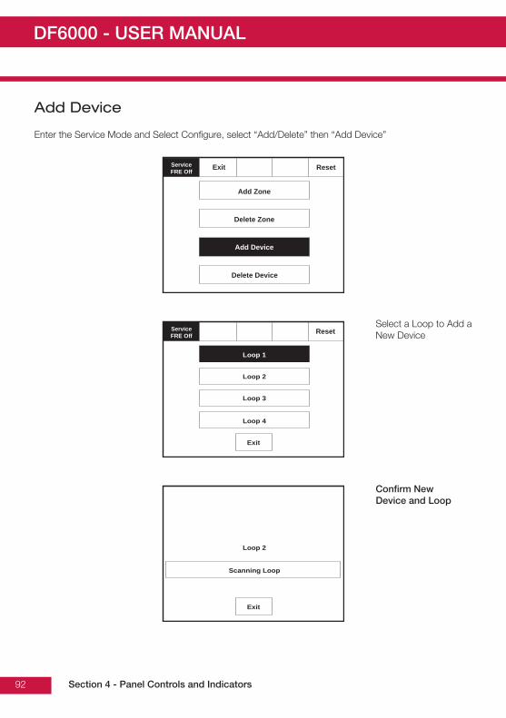
DF6000 - USER MANUAL
92
Add Device
Enter the Service Mode and Select Configure, select “Add/Delete” then “Add Device”
Section 4 - Panel Controls and Indicators
Select a Loop to Add aNew Device
Confirm NewDevice and Loop
Loop 2
Scanning Loop
Exit
ResetServiceFRE Off
Loop 1
Loop 2
Loop 3
Loop 4
Exit
ServiceFRE Off
Exit
Add Zone
Delete Zone
Add Device
Reset
Delete Device

DF6000 - USER MANUAL
93
Delete Device
Enter the Service Mode and Select Configure, select “Add/Delete” then “Delete Device”
Section 4 - Panel Controls and Indicators
Select a Device toDelete
Confirm or CancelDeletion
Delete device 3?
Device 3Loop 1, Address 3. Device Type Opto / Thermal
Yes No
ResetServiceFRE Off Exit
Touch row to delete
001 Device 1, Zone 1Loop: 1, Zone 1, Type: Opto / Thermal
002 Device 2, Zone 2Loop: 1, Zone 2, Type: Opto / Thermal
003 Device 3, Zone 1Loop: 1, Zone 2, Type: Opto / Thermal
004 Device 4, Zone 2Loop: 1, Zone 2, Type: Opto / Thermal
005 Device 5, Zone 1Loop: 1, Zone 1, Type: Opto / Thermal
Goto
ServiceFRE Off
Exit
Add Zone
Delete Zone
Add Device
Reset
Delete Device

DF6000 - USER MANUAL
94
Configure Heat Detectors
Enter the Service Mode and Select Configure. Select “Configure Heat Detectors”
Select appropriate detector class
Section 4 - Panel Controls and Indicators
Select a Device toConfigure
ResetServiceFRE Off
Thermal A1R
Thermal BS
Thermal CS
Exit
ResetServiceFRE Off Exit
Touch row to delete
001 Device 1, Zone 1Loop: 1, Zone 1, Type: Opto / Thermal
002 Device 2, Zone 2Loop: 1, Zone 2, Type: Opto / Thermal
003 Device 3, Zone 1Loop: 1, Zone 2, Type: Opto / Thermal
004 Device 4, Zone 2Loop: 1, Zone 2, Type: Opto / Thermal
005 Device 5, Zone 1Loop: 1, Zone 1, Type: Opto / Thermal
Goto
ExitServiceFRE Off Reset
Programming I/Oand Sounders
Network
Change Passcode
Configure Zones
Change Text
Change Date/Time
Add/Delete
Configure Heat Detectors
Language
MuteBuzzer

DF6000 - USER MANUAL
95
Network
Enter the Service Mode and Select Configure. Select “Network”, This menu defines whether messagesare broadcast across the network or remain local.
Section 4 - Panel Controls and Indicators
ExitServiceFRE Off Reset
Programming I/Oand Sounders
Network
Change Passcode
Configure Zones
Change Text
Change Date/Time
Add/Delete
Configure Heat Detectors
Language
MuteBuzzer
ExitServiceFRE Off
Network
Network
Network
Network
Network
Network
Reset
Evacuate
Silence
Fire
Fault
Pre-Alarm
Receive message over network
EvacuateServiceFRE Off Reset
Exit
Network Filter
MuteBuzzer
SilenceAlarms
Configure Zones
EvacuateServiceFRE Off Reset
Exit
Panel 001
MuteBuzzer
SilenceAlarms
Panel 002
Panel 003
Enable
Enable
Enable

DF6000 - USER MANUAL
96
Password Protection
The Menvier DF6000 system has password protection which restricts access to the DISABLE Menu andto TEST/COMMISSIONING MODE. The password is a four digit code and the default number is 2214 foraccess level two and 143243 for access level 3. The password entry screen is accessed via thesupervisor mode button. Press supervisor mode and the password entry screen will be displayed, type inthe passcode and press Ok. If the wrong password is entered 3 times further access to thesystem is denied.
Section 4 - Panel Controls and Indicators
ServiceFRE Off 1
4 5 67 8 9
ok 0
2 3..............................
Cancel
Please enter code:

DF6000 - USER MANUAL
97
Section 5Appendix
Section 5 - Appendix

DF6000 - USER MANUAL
98
Spur Isolator - MSI850
Installation1. Fit the unit in position.2. Connect the unit according to the diagram below.
Notes:A spur isolator must be used when making spurs from the analogue addressable panel loop. Without thisunit, the self addressing features of the system will not function correctly.
No addressing of the interface is required. See control panel operation for details.
Standard Connections
Notes:1. Only connect cable screen to its adjacent earth terminal.2. For maximum spur length / load see BS5839 Pt 1:2002.3. This unit can only be used with Menvier MAB800 and JSB FXN720 detector bases and compatible
detectors.
Section 5 - Appendix
Analogue
addressable
loop
No end of line
resistor required
Out
InSpur
m
+
m
+
m
+
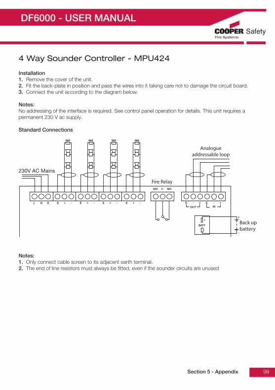
DF6000 - USER MANUAL
99
4 Way Sounder Controller - MPU424
Installation1. Remove the cover of the unit.2. Fit the back-plate in position and pass the wires into it taking care not to damage the circuit board.3. Connect the unit according to the diagram below.
Notes:No addressing of the interface is required. See control panel operation for details. This unit requires apermanent 230 V ac supply.
Standard Connections
Notes:1. Only connect cable screen to its adjacent earth terminal.2. The end of line resistors must always be fitted, even if the sounder circuits are unused
Section 5 - Appendix
L N E E + - E + - E + - E + - E E-
--
-+
++
+
N/ON/O
BATTBATT
C N/CN/C
OUTOUT ININ
6k86k8 6k86k8 6k86k8 6k86k8
230V AC Mains
Fire Relay
Analogueaddressable loop
Back upbattery

DF6000 - USER MANUAL
100
Zone Monitor Unit - MIU871
Installation1. Separate the two halves of the unit.2. Drill out (or knock out) the required cable entries in the surface mounting backbox.3. Fit the back-box in position and pass the wires into it.4. Connect the unit according to the diagram below.
Notes:No addressing of the interface is required. See control panel operation for details.
Standard Connections
Notes:1. This unit can only be used with JSB FXN520 detector base and compatible detectors.2. Only connect cable screen to its adjacent earth terminal.3. The end of line resistor must always be fitted, even if the spur is unused.4. Maximum spur length - See BS5839 Pt 1:2002 for aone coverage.5. Maximum number of callpoints allowed is unlimited.6. Detector zone end of line device is EOLM-1 (supplied)7. Callpoint zone has end of line resistor
Section 5 - Appendix
Callpoints can be connected with
detectors on detector zone if preferred
Callpoint
zone
Detector
zoneLoopInOut
Analogue addressable loop
12K
EOLM-1
Out
In
Out
In
-
-
-
-
+
+
+
+
+ + + +----E E E E
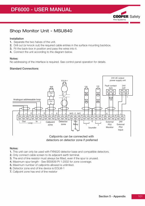
DF6000 - USER MANUAL
101
Shop Monitor Unit - MSU840
Installation1. Separate the two halves of the unit.2. Drill out (or knock out) the required cable entries in the surface mounting backbox.3. Fit the back-box in position and pass the wires into it.4. Connect the unit according to the diagram below.
Notes:No addressing of the interface is required. See control panel operation for details.
Standard Connections
Notes:1. This unit can only be used with FXN520 detector base and compatible detectors.2. Only connect cable screen to its adjacent earth terminal.3. The end of line resistor must always be fitted, even if the spur is unused.4. Maximum spur length - See BS5839 Pt 1:2002 for zone coverage.5. Maximum number of callpoints allowed is unlimited.6. Detector zone end of line device is EOLM-17. Callpoint zone has end of line resistor
Section 5 - Appendix
Callpoints can be connected with
detectors on detector zone if preferred
Callpoint
zone
Detector
zone
Analogue addressable loop
Out
In
+FireRelay
Sounder
ExternalPSU
Monitor
24VExternal
PSUInput
LoopInOut
6K8
EOLM-1
12K 12K
12K
24V dC output
power supply unit
Fault contact
N/O
24V
O/P
+
+-
-
Out
In +
+-
-
1 2
+ -- E
+-
N/O N/CC +-+ -+ -+-+-+-+-E E E E E

DF6000 - USER MANUAL
102
1 Way Input / Output Unit - MIO1240
Installation1. Separate the two halves of the unit.2. Drill out (or knock out) the required cable entries in the surface mounting back-box.3. Fit the back-box in position and pass the wires into it.4. Connect the unit according to the diagram below.
Notes:No addressing of the interface is required. See control panel operation for details.
Standard Connections
WARNING: Segregate mains cable from other connections to this unit. 230 V Relay output is un-fused. Ensure that the 230 V supply feeding this unit is adequately protected
Notes:1. Only connect cable screen to its adjacent earth terminal.2. The end of line resistor must always be fitted, even if the inputs are unused.
Section 5 - Appendix
Only connected cable screen to its adjacment earth terminal.
The end of line resistor must always be be fitted, even if the spur is unused.
Analogue addressable loop
In Out Spur Input
Volt-Free Output
230V rated
5K6
22K
E C N/C N/OE E- --+ ++

DF6000 - USER MANUAL
103
Detector Base Wiring - MAB800
Supply Voltage 18 - 30 V dcCable Size 0.5 - 2.5mm²Recommended cable types FIRETUF,FP200 or MICCMounting hole centres 50 - 80mm
Wiring Hints1. Each terminal is suitable for clamping up to 2 wires2. Clamping of 2 wires of very different diameters under one screw is not recommended.3. Suitable for mounting to mounting boxes with 50-80mm fixing centres. General If difficulty is
experienced when mounting the detector, this may be due to the following:4. Wiring causing an obstruction - move or shorten wires.5. Although the base is tolerant to uneven mounting surfaces, a very uneven surface may cause the base
to deform when the mounting screws are tightened down - loosen screws to reduce this or slide base to a more flat position.
WARNING: Do not use high voltage testers when detectors or control panel are connected to thesystem.
Section 5 - Appendix
+
+VIN
- VE COM OUT
2
4
1
3
2
4
1
3
earth screen of cable to be continuous between detectors
- VE COM IN
Attention: If using the outer connection on terminal 2, ensure the operation of the switch is not impeded and that there no shorts between terminal 2 and the switch contact.
Ensure that the cable does not short onto the contact
Analo
gue a
dd
ressab
le
fire
ala
rm p
anel
Lo
op
sta
rtL
oo
p fi
nis
h
S+
S-
F-
F+
remote indicator
LED (optional)

DF6000 - USER MANUAL
104
System Wiring
Section 5 - Appendix
NO
CN
C0
VS+
S+
F-
F-
F+
F+
S-
S-
-+2
6V
++
--
+-
+-
Rx
CTS
RTS
OV
Tx
Tx-
Tx+
S+
F-
F+
S-
S+
F-
F+
S-
-+ 1 -
+ 2 -
+ 2 -
+ 1 -
+ 2
An
y 3
00
series a
nalo
gu
e s
en
so
r can
be c
on
necte
d t
o t
he lo
op
MIM
IC
Rep
eate
r
MO
DE
M/P
C
R&
23
2
So
un
der
Circ
uit 2
So
un
der
Circ
uit 1
Cla
ss
Ch
an
ge
Lo
op
1L
oo
p 2
Lo
op
3L
oo
p 4
Lo
op
Circ
uits
Fire
P/E
Fire
R/E
+2
4V
O/P
Fau
lt
Rela
y
AU
X
Rela
y

DF6000 - USER MANUAL
105
Weatherproof Wall Sounder - MAS850LPS/WP
Installation1. Drill required holes for the cable gland fixing2. Drill out the required fixing holes3. Fix to mounting surface using two suitable screws
Standard Connections
WARNING: Do not use high voltage testers if any equipment is connected to the system. earthscreen must be continuous along entire length of loop.
Section 5 - Appendix
Analogue addressable loop
In Out
E +- E +-

DF6000 - USER MANUAL
106
Internal Wall Sounder - MAS850/LPS
Installation1. Fix to mounting surface using two suitable screws - the rear gasket fits underneath the base and the
sounder gasket fits inside the base.
Standard Connections
WARNING: Do not use high voltage testers if any equipment is connected to the system. earthscreen must be continuous along entire length of loop.
Note:Care should be taken to ensure the cable does not put stress on the circuit board
Section 5 - Appendix
Analogue addressable loop
In Out
E +- E +-

DF6000 - USER MANUAL
107
Base Sounder - MAS850 + MASC
Supply Voltage 17 ~ 32 V dcCable Size / type 0.5 ~ 2.5mm/ FIRETUF, FP200 or MICCStandby current < 320 uAOperating temperature -10 to +55 degrees C (95%RH)Sound output @ +/-3dB (set by panel) Low volume: 84 dB @ <4 mA
Medium volume: 92 dB @ <8 mAHigh volume: 95 dB @ <12 mA
Tones (set by panel) Continuous 910 HzPulsed: 910 Hz / 0 Hz pulse 1 HzTwo tone: 610 Hz / 910 Hz @ 1 Hz cycleSlow whoop: 500-1200 Hz in 3.5 seconds / 0.5secs gap
Section 5 - Appendix
+ +- - + +- -
An
alo
gu
e a
dd
ressab
le
fire
ala
rm p
an
el
Lo
op
sta
rtLo
op
finis
h
S+
S-
F-
F+
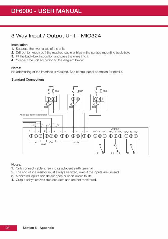
DF6000 - USER MANUAL
108
3 Way Input / Output Unit - MIO324
Installation1. Separate the two halves of the unit.2. Drill out (or knock out) the required cable entries in the surface mounting back-box.3. Fit the back-box in position and pass the wires into it.4. Connect the unit according to the diagram below.
Notes:No addressing of the interface is required. See control panel operation for details.
Standard Connections
Notes:1. Only connect cable screen to its adjacent earth terminal.2. The end of line resistor must always be fitted, even if the inputs are unused.3. Monitored inputs can detect open or short circuit faults.4. Output relays are volt-free contacts and are not monitored.
Section 5 - Appendix
Analogue addressable loop
5K6 5K65K6
22K 22K 22K
LoopIn Out Inputs
Outputs
N/O C N/C N/O C N/C N/O C N/CE E- + - + - + - + - +

DF6000 - USER MANUAL
109
Loop Powered Beacon - MAB870
Connection DetailsEarth screen of cable to be continuous between beacons
WARNING: Do not use high voltage testers if any equipment is connected to the system.
Standard Connections
Section 5 - Appendix
Analogue addressable loop
In Out
E +- E +-
Loop in Loop out

DF6000 - USER MANUAL
110
Callpoint - MBG813 / MBG817
Standard Connections
Section 5 - Appendix
Analogue addressable loop
In Out
E +- E +-
Loop in Loop out

DF6000 - USER MANUAL
111
EN54 Product Spec Label
Note: X=2 on a 2 Zone Panel / X=4 on a 4 Zone Panel
Section 5 - Appendix
Powe rON
Powe rON FIREFIRE General
FAUL TGeneralFAUL T
SystemDISABL ESystem
DISABLESystemFAUL T
SystemFAUL T
SystemTEST
SystemTEST
Charg eFAUL T
Charg eFAUL T
BatteryFAUL TBatteryFAUL T
1 2 3 4 5 6 7 8 9
2121 2222 2323 2424
1010 1111 1212
1313 1414 1515 1616 1717 1818 1919 2020
2525 2626 2727 2828 2929 3030 3131 3232 3333 3434 3535 3636
3737 3838 3939 4040 4141 4242 4343 4444 4545 4646 4747 4848
4949 5050 5151 5252 5353 5454 5555 5656 5757 5858 5959 6060
6161 6262 6363 6464 6565 6666 6767 6868 6969 7070 7171 7272
7373 7474 7575 7676 7777 7878 7979 8080 8181 8282 8383 8484
8585 8686 8787 8888 8989 9090 9191 9292 9393 9494 9595 9696
ZonesZones
Label: D6K XBPR200-04-517-01
Label: D6K XAPR200-04-518-01
Note: If the panel is recessed this label must be placed on the front of the panel

DF6000 - USER MANUAL
112
Battery Disposal Instructions
Although batteries contain lead and small amounts of antimony and arsenic, they are safe if handledaccording to the accompanying guide. The battery cells must not be dismantled as this involves severalhazards, which are best handled under controlled conditions, using specialised equipment. No attemptshould be made to repair any batteries; they should be treated as disposable when they have outlivedtheir use. Batteries must be disposed of in accordance with current waste disposal and pollutionlegislation and in particular; The Environment Protection Act 1990, Special Waste Regulation 1996. It isrecommended that the following authorities are contacted before any attempt is made to dispose ofbatteries; Environment Agency Local office, Local Authority Environmental Health or Waste Handlingdepartment.
Section 5 - Appendix

DF6000 - USER MANUAL
113
CE Marking
Section 5 - Appendix
0832 – CPD – 1060 0832 – CPD – 1060714h/01 714h/01
EN 54-2 1997 & A1:2006
DF6000Control and indicating equipment for fire detection and fire
alarm systems for buildingsEN 54-2 Clause
Options Provided
7.8 Output to fire alarm devices7.9.1 Output to fire alarm routing equipment7.10.1 Output to automatic fire protection equipment (type A)7.10.2 Output to automatic fire protection equipment (type B)7.11 Delays to outputs7.12.3 Dependencies on more than one alarm signal-Type C7.13 Alarm counter8.9 Output to fault routing equipment9.5 Disablement of each point10 Test condition
Other technical data: see Doc. PR200-04-513 held by themanufacturer
EN 54-4 1997 & A1:2002 A2:2006
DF6000Power supply equipment for fire detection and fire alarm
systems for buildings
Other technical data: see Doc. PR200-04-513 held by themanufacturer
Cooper Lighting and Safety LtdWheatley Hall Road
DoncasterSouth Yorkshire
DN2 4NB
09
Cooper Lighting and Safety LtdWheatley Hall Road
DoncasterSouth Yorkshire
DN2 4NB
09
E RC T I FN I CO AI TT IN OE NV E BR OP AS RS DOL
LPCBE RC T I FN I CO AI TT IN OE NV E BR OP AS RS DOL
LPCB
CC1809
Head Office
SalesTel: 01302 303999
Fax: 01302 303333
Email: [email protected]
TechnicalTel: 01302 303350
Fax: 01302 303332
Email: [email protected]
ExportTel: 01302 303334
Fax: 01302 303345
Email: [email protected]
ServiceTel: 01302 303352
Fax: 01302 303332
Email: [email protected]
Web: www.cooperfire.com
Head Office
Cooper Lighting and Safety Ltd
Wheatley Hall Road
Doncaster
South Yorkshire
DN2 4NB