Embed Size (px)
DESCRIPTION
Dey Tanmoy Thesis
Citation preview
% - Conjugated Polymers for Electrochromic and Photovoltaic Applications
Tanmoy Dey, Ph.D.
University of Connecticut, 2010
Abstract
Electrochromism is a process by which a material can change its electronic-
optical properties upon charge injection/removal. Conjugated polymers are an
interesting class of electrochromic materials because of their color tunability, high
optical contrasts, fast switching speeds, and processability. Poly(3,4-
propylenedioxy)thiophenes (PProDOT) are a substantial subclass of materials in
conjugated polymer electrochromics due to their high optical contract between
the bleached and colored states. Common derivatives of this molecule are
typically made at the beta position with respect to oxygen on the seven
membered ring. PProDOTs with methyl and benzyl substituents (beta position
with respect to oxygen) are two of the more successful due to their high contrast.
We have found that there is a much more substantial effect when PProDOT is
derivatized in the positions alpha to the oxygen. For example, two t-butyl groups
with each placed alpha to the oxygen in PProDOT incurs a 200 nm shift in the
lambda max (365 nm) compared to having two methyl groups with each placed
alpha to the oxygen. The dimethyl derivative is blue in color whereas the di-t-
butyl, dihexyl, diisopropyl is showing yellow, orange and red color respectively .
The polymer of this new derivative, P13ProDOT-TB2 and P13ProDOT-Hex2 is
organic-soluble and can be processed by a variety of solution methods, including
spray coating. Furthermore we have also studied some selenium based polymer
for electrochromic application. Poly(3,4-propylenedioxy)selenophenes
(PProDOS) is showing better optical contrast, stability and faster switching speed
as compared to their sulfur analogs.
Low band gap conducting polymers (CPs) have relatively low absorption in the
visible region, in their conducting states, making them promising candidates for
optically transparent electrode, hole- injection layer for light-emitting diodes and
suitable donor material for Photovoltaics. The monomer, Seleno[3,2-c]thiophene
and Seleno[3,4-£>]thiophene, were electrochemically and polymerized to produce
new low band gap conducting polymer, poly(Seleno[3,2-c]thiophene) (PS32cT)
and Poly(Seleno[3,4-ib]thiophene) (PS34bT), having a low band gap of 1.03 eV
and 1.50 eV respectively. Besides from the suitable energy gap, they also offer a
good match of the absolute energy levels with the other materials in the
photovoltaic device. The HOMO of the low band gap polymers agree with the
work function of ITO and LUMO matches with the acceptor level of PCBM. This
overlap is very important to the function of photovoltaic devices.
In a different approach we describe a new alternative route for the synthesis of
thieno[3,4-b]thiophene, alkyl derivatives thereof, seleno[3,4-b]thiophene, and
thieno[3,4-b]furan made from inexpensive starting materials, such as thiophene-
2-carboxylic acid and furan-2-carboxylic acid. Such fused heterocycles are of
great interest for low band gap organic semiconductors and applications
including OLEDs, organic photovoltaic cells, and electrochromic applications.
n - Conjugated Polymers for Electrochromic and Photovoltaic Applications
Tanmoy Dey, Ph.D.
B.Sc. Hons., University of Calcutta, 1999
B.Tech., University of Calcutta, 2002
A Dissertation
Submitted in Partial Fulfillment of the
Requirements for the Degree of
Doctor of Philosophy
At the
University of Connecticut
2010
UMI Number: 3451416
All rights reserved
INFORMATION TO ALL USERS The quality of this reproduction is dependent upon the quality of the copy submitted.
In the unlikely event that the author did not send a complete manuscript and there are missing pages, these will be noted. Also, if material had to be removed,
a note will indicate the deletion.
UMI' Dissertation Publishing
UMI 3451416 Copyright 2011 by ProQuest LLC.
All rights reserved. This edition of the work is protected against unauthorized copying under Title 17, United States Code.
ProQuest LLC 789 East Eisenhower Parkway
P.O. Box 1346 Ann Arbor, Ml 48106-1346

Copyright by
Tanmoy Dey
2010
APPROVAL PAGE
Doctor of Philosophy Dissertation
7t - Conjugated Polymers for Electrochromic and Photovoltaic Applications
Presented By
Tanmoy Dey, B.Sc. (Hons.), B.Tech.
Major Advisor>^"^ \
^—RcQf^Gre^Qry A. Sotzing
Associate Advisor.
Prof. Amy Howell
Associate Advisor
Prof. Rajeswari Kasi
University of Connecticut
2010
<^WY^ O^W^e^L
/ ^ ^ A ^ ^ 7 K / / C

To my Mother
in

Acknowledgments
Leaving the home country for pursuing my Ph.D. studies was the most difficult
decision I ever had to make, and I would never have been able to go through this
without my mother's support. Of course this learning experience would not have
been so rich without the guidance of my research advisor Prof. G.A. Sotzing. He
handled the research group as a businessman, educating us very well for our
future industrial careers. I wish to express my sincere gratitude for his valuable
guidance, motivation, and suggestions. He allowed me to work on research
projects that I found particularly interesting and prepared me for life after
graduate school.I would like to thank my associate advisors, Professor Amy
Howell and Professor Rajeswari Kasi for their advice and direction during my
research. I also thank Professor Adamson and Professor Selampinar for being
my examiners and investing their valuable time. I would also like to thank
Professor Zeki Buyukmumcu's collaboration and contribution in the seleno[3,4-
b]thiophene and 1,3-ProDOT work.
A special thank you goes to my labmates for their help and support. I appreciate
Dr. Arvind Kumar, Dr. Selman Yavuz, Dr. Jayesh Bokria, Dr. Mathew Ombaba,
Dr. Yogesh Ner, Dr. Chris Asemota, Dr. Jia Choi and Dr. Mike Invemale for their
guidance, especially through the tough times. It was a great pleasure to work
with Ki-Ryong Lee, Daminda Navaratne, Yujie Ding, Donna Mamangun, John
Hyun Park and Yani Feng on several projects.
IV

I extent thanks to all the IMS and Chemistry staff for providing me with technical
and non-technical assistance in UCONN. I also thank all my friends for their
encouragement and just being there.
Last but not least, I want to thank my wife Madhumita. She has always been very
supportive of me, pushing me to reach higher and to achieve more than I thought
I could.
v
LIST OF FIGURES
Figure # Caption Page#
1.1 Common conjugated polymers. 3
1.2 Chemical Structures of Polyethylene dioxythiophene 6
(PEDOT) and Polypropylenedioxythiophene (PProDOT).
1.3 Three most common viologen redox states. 11
1.4 Poly(thiophene) oxidative doping 16
1.5 Electrochromic states of various conducting polymers 18
1.6 Energy band formation during polymerization of conjugated 20
Monomer.
1.7 Effect on the polymer optical band gap upon modification of 22
backbone rotational freedom
1.8 Aromatic and quinonoidal forms of conjugated polymers 23
1.9 Color tuning of thiophenes though intrachain twisting 25
1.10 Effect of electron donating or electron withdrawing 26
substituents on Egof Conjugated Polymers
1.11 Factors affecting the Eg of conducting polymer 27
1.12 Davydov splitting in interchain aggregates 29
1.13 The schematic structure and operation of an organic bulk 35
heterojunction solar cell
1.14 J-V measurement on a bulk heterojunction solar cell 36
VI
1.15 Solar Spectrum Comparison 38
2.1 Electrochemical set up for a three electrode cell 59
2.2 Conjugated polymer electrodeposition techniques : Cyclic 61
Voltammetry
2.3 Scan rate dependence of P13ProDOT-Me2 64
2.4 EQCM setup where gold coated piezoelectric quartz crystal 68
is used as working electrod
2.5 Experimental set up for in situ spectroelectrochemistry. 69
2.6 CIE u ^ coordinates of Polyl3ProDOT-R2 72
3.1 Chemical structures of 1,3 di substituted ProDOT 80
3.2 Overlays of UV-Vis absorption of neutral P13ProDOT-R2 82
3.3 Electrochemical polymerization of 13ProDOT-TB2 98
3.4 Electrochemical polymerization of 13ProDOT-IP2 99
3.5 Electrochemical polymerization of 13ProDOT-Me2 100
3.6 Electrochemical polymerization of 13ProDOT-Bz2 101
3.7 CV scans of polymer, P13ProDOT-TB2 deposited onto Pt 103
button electrode at different scan rates
3.8 CV scans of polymer, P13ProDOT-IP2, deposited onto Pt 104
button electrode at different scan rates
3.9 CV scans of polymer, P13ProDOT-Me2, deposited onto Pt 105
button electrode at different scan rates
3.10 CV scans of polymer, P13ProDOT-Hex2, drop casted onto 106
Pt button electrode at different scan rates
vii
3.11 CV scans of polymer, P13ProDOT-Bz2, deposited onto Pt 107
button electrode at different scan rates
3.12 Spectroelectrochemical data (350-2200 nm) for 110
P13ProDOT-TB2 film (100 nm thick) on ITO-coated glass
at different applied potentials
3.13 Spectroelectrochemical data for P13ProDOT-IP2 film (ca. 111
250nm thick) on ITO-coated glass at different applied
potentials
3.14 Spectroelectrochemical data for P13ProDOT-Me2 film (ca. 112
250nm thick) on ITO-coated glass at different applied
potentials
3.15 Spectroelectrochemical data for P13ProDOT-Bz2 film (ca. 113
250nm thick) on ITO-coated glass at different applied
potentials
3.16 Spectroelectrochemical data for P13ProDOT-Hex2 film (ca. 114
250nm thick) on ITO-coated glass at different applied
potentials
3.17 Spectra of P13ProDOT-TB2, electrochemically 117
(chronocoulometry at +1.1 V) deposited on ITO
3.18 Solution oxidation of chemically polymerized (FeCI3) 118
P13ProDOT-TB2 by UV-vis-NIR spectroscopy in THF as a
function of oxidant concentration using SbCI5.
3.19 Solution Spectra of P13ProDOT-Hex2, electrochemically 119
viii
(chronocoulometry at +1.1 V) deposited on ITO.
3.20 Spray coated P13ProDOT-Hex2 on ITO 119
3.21 CIE iT v' coordinate plot of the neutral states of 121
P13ProDOT-R2
4.1 Various combinations of fused five-membered heterocycles 132
4.2 Structure of thieno[3,4-b]thiophene (T34bT), its 135
derivatives, seleno[3,4-b]thiophene (S34bT), and
thieno[3,4-b]furan (T34bF).
5.1 Chemical structures of ethylenedioxythiophene (1), 168
thieno[3,4-b]furan (2), and thieno[3,4-b]thiophene
(3),ethylenedioxyselenophene (4), seleno[3,2-c]thiophene
(5), seleno[3,4-b]thiophene (6)
5.2 Cyclovoltammetric polymerization (electrochemical), 20 172
scans, of Selono[3,2-c]thiophene (S32cT) (A), Selono[3,4-
b]thiophene (S34bT) (B), (0.01 M) in 0.1 M
TBAP/acetonitrile electrolyte solution at a scan rate of 100
mV/s using a Pt button working electrode.
5.3 Scan rate dependency of poly(Seleno[3, 2- 176
c]thiophene)(A), poly(Seleno[3, 4- b]thiophene)(B)
5.4 Chronocoulometry obtained for redox switching (A) 177
PS32cT and (B) PS34bT
5.5 Spectroelectrochemistry spectrum of a 0.2 |iim thick 180
ix
PS32cT and PS34bT films on ITO glass.
5.6 Vis-NIR spectrum of a 0.05 |im thick PS32cT and PS34bT 183
film on ITO glass. The film was chemically reduced using
0.2 % v/v hydrazine solution in acetonitrile, and oxidized
using 0.2% v/v antimony (V) chloride solution in
acetonitrile.
5.7 1s t and 2nd scan of p- and n-doping cyclic voltammetry for 185
PS32cT and PS34bT
5.8 Optimized calculated structure of S32cT dimmer and 187
S34bT tetramer
5.9 Solar Spectrum Material Comparison 189
5.10 Band Levels (in eV vs. Vacuum) of a device based on 191
PS32cT (A) and PS34bT (B) as donar material and PCBM,
and movement of the electron (e) and hole (o) created as
a result of NIR absorption.
6.1 Chemical structures of ProDOS-Me2 and ProDOS-Hex2 202
6.2 Electrochemical polymerization of 10 mM ProDOS-Me2 and 210
ProDOS-Hex2
6.3 Swithing speed of PProDOS-Me2 212
6.4 Scan rate dependency of polymer, PProDOS-Me2 and 213
PProDOS-Hex2 deposited onto Pt button electrode at
different scan rates
6.5 In-situ spectroelectrochemistry of PProDOS-Me2 and 215
x

PProDOS-Hex2 deposited onto ITO-coated-glass
xi
LIST OF SCHEMES
Scheme # Caption Page#
3.1 Synthesis of meso-2,2,6,6-Tetramethyl-3,5-heptanediol 84
(TMHDiol)
3.2 Synthesis of 13ProDOT-TB2. 86
3.3 Synthesis of 5-hydroxy-2,6-dimethylheptan-3-one 87
(HDMH-One)
3.4 Synthesis of 13ProDOT-IP2 89
3.5 Synthesis of 13ProDOT-Me2. 90
3.6 Synthesis of pentadecane-7,9-diol 91
3.7 Synthesis of 13ProDOT-Hexyl2 92
3.8 Synthesis of 1,5-diphenylpentane-2,4-diol 94
3.9 Synthesis of 13ProDOt-Bz2 95
3.10 Chemical Polymerization of 13ProDOT-TB2 and 116
13ProDOT-Hex2
4.1 137 Synthetic procedure for thieno[3,4-£>]thiophene (T34bT)
and seleno[3,4-b]thiophene (S34bT).
4.2 Synthetic procedure for 2-substituted thieno[3,4- 138
£>]thiophenes
4.3 Synthetic procedure for thieno[3,4-/?]furan (T34bF). 139
5.1 Synthesis of seleno[3,2-c]thiophene 169
5.2 Synthesis of seleno[3,4-b]thiophene 171
xii
6.1
6.2
6.3
6.4
6.5
Synthetic of 3,5-DimethoxySelenophene (DMOS)
Synthetic of ProDOS-Me2(ProDOS-Me2)
Synthesis of 2,2-Dihexylmalonic Acid Diethyl Ester
Synthesis of 2, 2-Dihexyl Propane-1, 3-diol
Synthesis of ProDOS-Hex2
204
205
206
207
208
Xlll
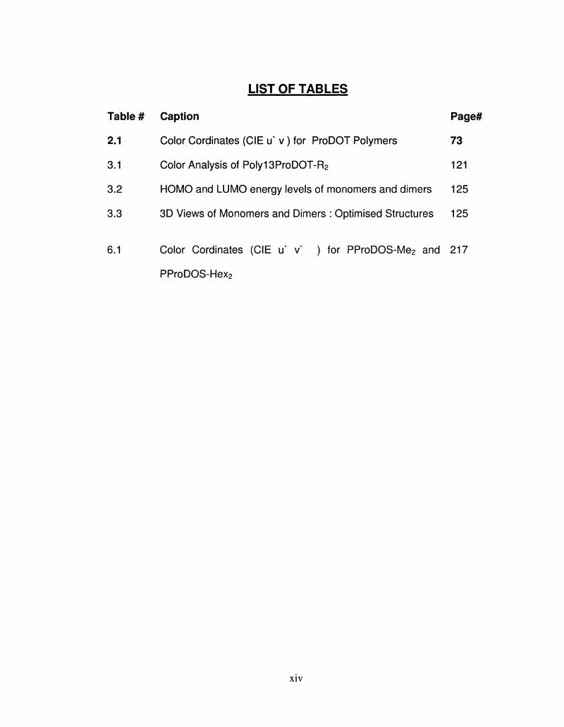
LIST OF TABLES
Caption Page#
Color Cordinates (CIE u v) for ProDOT Polymers 73
Color Analysis of Polyl 3ProDOT-R2 121
HOMO and LUMO energy levels of monomers and dimers 125
3D Views of Monomers and Dimers : Optimised Structures 125
Color Cordinates (CIE u v ) for PProDOS-Me2 and 217
PProDOS-Hex2
XIV
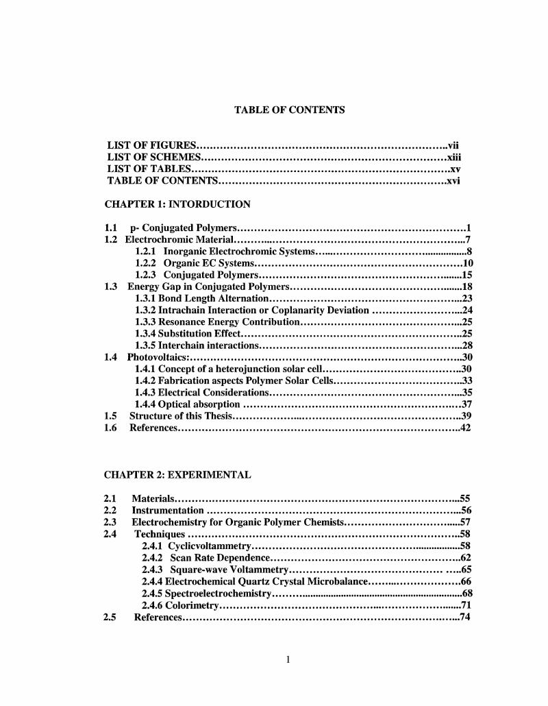
TABLE OF CONTENTS
LIST OF FIGURES vii LIST OF SCHEMES xiii LIST OF TABLES xv TABLE OF CONTENTS xvi
CHAPTER 1: INTORDUCTION
1.1 p- Conjugated Polymers 1 1.2 Electrochromic Material 7
1.2.1 Inorganic Electrochromic Systems 8 1.2.2 Organic EC Systems 10 1.2.3 Conjugated Polymers 15
1.3 Energy Gap in Conjugated Polymers 18 1.3.1 Bond Length Alternation 23 1.3.2 Intrachain Interaction or Coplanarity Deviation 24 1.3.3 Resonance Energy Contribution 25 1.3.4 Substitution Effect 25 1.3.5 Interchain interactions 28
1.4 Photovoltaics: 30 1.4.1 Concept of a heterojunction solar cell 30 1.4.2 Fabrication aspects Polymer Solar Cells 33 1.4.3 Electrical Considerations 35 1.4.4 Optical absorption 37
1.5 Structure of this Thesis 39 1.6 References 42
CHAPTER 2: EXPERIMENTAL
2.1 Materials 55 2.2 Instrumentation 56 2.3 Electrochemistry for Organic Polymer Chemists 57 2.4 Techniques 58
2.4.1 Cyclicvoltammetry 58 2.4.2 Scan Rate Dependence 62 2.4.3 Square-wave Voltammetry 65 2.4.4 Electrochemical Quartz Crystal Microbalance 66 2.4.5 Spectroelectrochemistry 68 2.4.6 Colorimetry 71
2.5 References 74
1
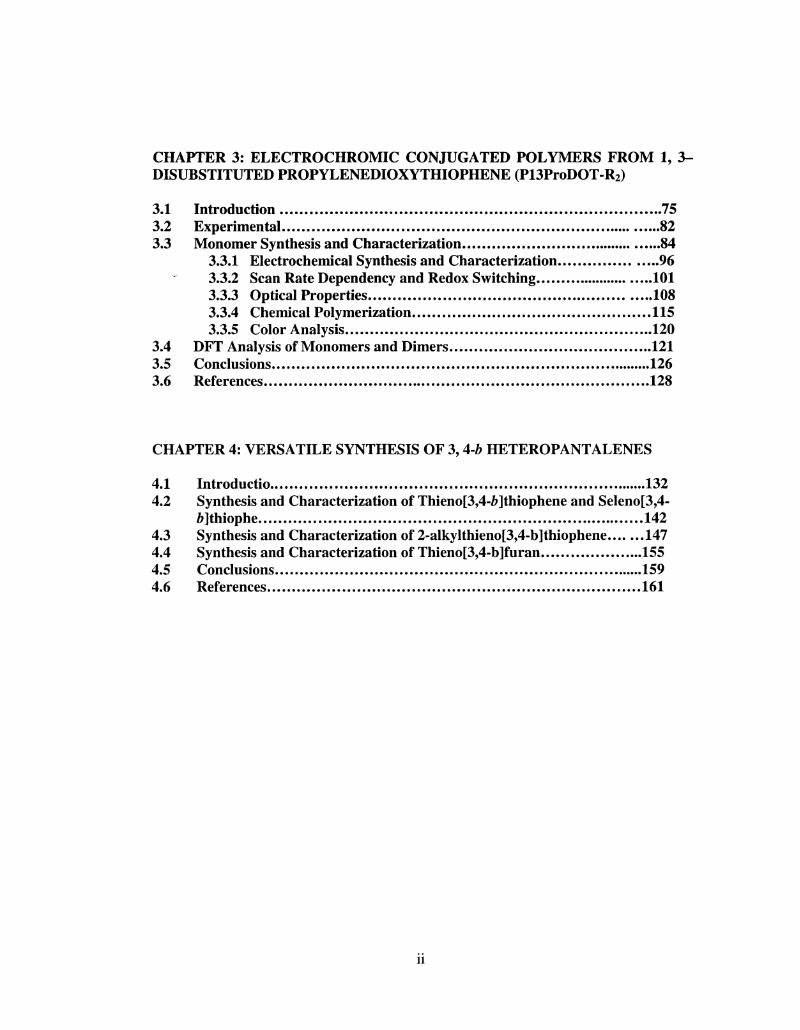
CHAPTER 3: ELECTROCHROMIC CONJUGATED POLYMERS FROM 1, 3 -DISUBSTITUTED PROPYLENEDIOXYTHIOPHENE (P13ProDOT-R2)
3.1 Introduction 75 3.2 Experimental 82 3.3 Monomer Synthesis and Characterization 84
3.3.1 Electrochemical Synthesis and Characterization 96 3.3.2 Scan Rate Dependency and Redox Switching 101 3.3.3 Optical Properties 108 3.3.4 Chemical Polymerization 115 3.3.5 Color Analysis 120
3.4 DFT Analysis of Monomers and Dimers 121 3.5 Conclusions 126 3.6 References 128
CHAPTER 4: VERSATILE SYNTHESIS OF 3, 4-b HETEROPANTALENES
4.1 Introductio 132 4.2 Synthesis and Characterization of Thieno[3,4-6]thiophene and Seleno[3,4-
Z>]thiophe 142 4.3 Synthesis and Characterization of 2-alkylthieno[3,4-b]thiophene 147 4.4 Synthesis and Characterization of Thieno[3,4-b]furan 155 4.5 Conclusions 159 4.6 References 161
l i
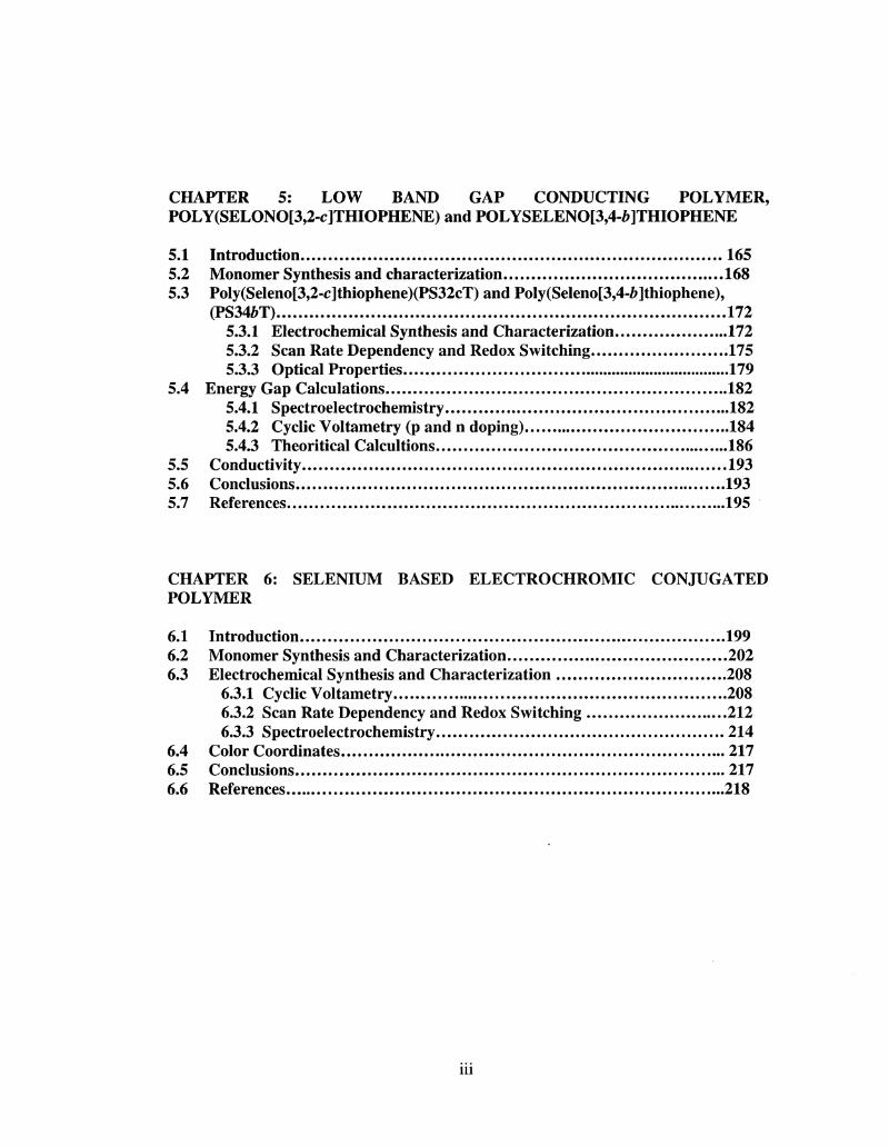
CHAPTER 5: LOW BAND GAP CONDUCTING POLYMER, POLY(SELONO[3,2-c]THIOPHENE) and POLYSELENO[3,4-6]THIOPHENE
5.1 Introduction 165 5.2 Monomer Synthesis and characterization 168 5.3 Poly(Seleno[3,2-c]thiophene)(PS32cT) and Poly(Seleno[3,4-6]thiophene),
(PS346T) 172 5.3.1 Electrochemical Synthesis and Characterization 172 5.3.2 Scan Rate Dependency and Redox Switching 175 5.3.3 Optical Properties 179
5.4 Energy Gap Calculations 182 5.4.1 Spectroelectrochemistry 182 5.4.2 Cyclic Voltametry (p and n doping) 184 5.4.3 Theoritical Calcultions 186
5.5 Conductivity 193 5.6 Conclusions 193 5.7 References 195
CHAPTER 6: SELENIUM BASED ELECTROCHROMIC CONJUGATED POLYMER
6.1 Introduction 199 6.2 Monomer Synthesis and Characterization 202 6.3 Electrochemical Synthesis and Characterization 208
6.3.1 Cyclic Voltametry 208 6.3.2 Scan Rate Dependency and Redox Switching 212 6.3.3 Spectroelectrochemistry 214
6.4 Color Coordinates 217 6.5 Conclusions 217 6.6 References 218
in
CHAPTER 1
7i- Conjugated Polymers for Electrochromics and
Photovaltaics Applications
1.1 n- Conjugated Polymers
Interest in the field of conjugated polymers (CPs) has increased tremendously
following the discovery of iodine-doped polyacetylene as conducting polymeric
material.1 Heeger, Macdiarmid and Shirakawa were awarded with the Nobel
Prize in Chemistry in 2000 in recognition of this discovery as well as their
contribution in the field of conducting polymers.2 CPs have existed since 1962,
when the electrochemical synthesis of polyaniline was reported by H. Letheby
(PAni).3 Polyaniline is also known as "aniline black"; this material was formed by
oxidation of aniline under mild conditions and was used in the printing industry.4
The first polymerization of acetylene to form polyacetylene (PAc, a) was reported
in 1958 by Natta and coworkers.5 Because PAc obtained was insoluble and
infusible in nature, the material gained little interest at that time. The inspiration
that conjugated polymers could be good electrical conductors roots back to the
1960s when MacDiarmid and others revealed that poly(sulfurnitride) (SN)X, a
polymeric inorganic explosive,6 has a high conductivity.7 The remarkable high
1
electrical properties of (SN)X represented a important step in the field of
conjugated polymers.
The modern age of conjugated polymers started during late 1970s when films
of PAc were found to exhibit a 12 order of magnitude increase in electrical
conductivity when doped with iodine vapors.1"2 The synthetic procedure of
making PAc was based upon a route discovered in 1974 by Shirakawa by
accidental addition of 1,000 times more catalyst during the chemical
polymerization of acetylene. Although initially it was thought that PAc would
replace metals in air and space applications, its environmental instability as well
as its insolubitily created major obstacle for any practical use. However, PAc,
being the simplest model from this class, remains the archetype of conducting
polymers and is still subject to extensive research work.
2
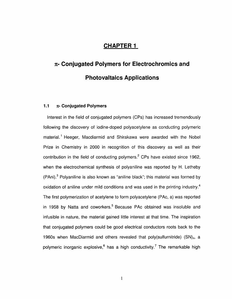
Figure 1.1 Common conjugated polymers, (a) poly(acetylene), (b) poly(pyrrole),
(c)poly(thiophene), (d) poly(3,4-ethylenedioxythiophene), (e) poly(p-phenylene),
(f) poly(p-phenylene vinylene), (g) poly(aniline), (h) poly(fluorene), and (i)
poly(carbazole).
The prospect of synthesizing new conjugated polymers with improved
rheological and electrical properties began to draw the interest of synthetic
chemists in the early 1980s. At the same time, the discovery of polypyrrole (PPy,
b) with highly conducting and homogeneous, free-standing films via oxidative
electropolymerization 8 focused the research efforts towards the development of
conjugated poly(heterocycles). Followed by the invention of PPy,
electrochemical polymerization focusing film forming and conducting properties
3
was rapidly extended to other aromatic hetero cyclic compounds such as aniline,
thiophene, furan, indole, carbazole, indole, azulene, pyrene, and fluorene.9"10
Despite their poor conductivity compare to PAc, the interest in conjugated
poly(heterocycles) shown in Figure 1.1 (compounds b-i) was due to their
superior environmental stabilities in their p-doped state. Moreover
poly(heterocycles) showed better opto-electronic properties than that of PAc.11
Among these so-called "first generation" CPs, polythiophene (PT, c) has rapidly
gained considerable interest, mainly due to its structural versatility and enhanced
environmental stability both in neutral and p-doped states. However, PTs are not
stable at the electrical/chemical potentials required for their polymerization. This
effect is known as "PT paradox" which means that the polymer degradation
competes with its polymerization, leading to the formation of polymers with a high
content of overoxidized, non-electroactive material. The problem of
polythiophene polymerization can be circumvented by modifying chemical
structure of the monomer in order to stabilize the polymer to the degradation.
Another advantage of this approtch is other properties such as processabillity,
optical properties can also be tuned. This gives the motivation to the synthesize a
vast family of PT derivatives with varied properties.12"13
Among the 'second generation conjugated polymers1 the 3,4-ethylenedioxy
derivative of PT (PEDOT, d) proved itself as an excellent candidate for variety of
electro-optical applications such as electrochromic devices, LEDs, capacitors
and sensors. Primarily PEDOT was developed to give a processable polymer (as
an aqueous dispersion) with a high degree of structrural order due to the lack of
4
a-p and (3-(3 couplings. PEDOT has gained tremendous attention, both
industrially and in academia due to its excellent opto-electrical properties. In
addition to its high electrical conductivity, PEDOT also exhibits high
electrochromic contrast with the major advantage of being almost transparent in
its doped conducting state.14"15 Other advantages include low monomer oxidation
potential, high stability in the doped form and an ease of derivatization at the
ethylenedioxy ring, thus allowing for state-of-the-art tuning of the materials'
electronic and optical properties. The industrial use of the polymer as an
antistatic layer in photographic films makes it the most extensively used
conjugated polymer to the date.16
Derivatization of the monomer with long alkyl or alkoxy pendant groups affords
polymeric materials that can be processed by common solution processing
techniques including spraying, inkjet printing, spin coating or solution
casting.17'18 .One drawback of neutral PEDOT based polymers is their instability
towards atmospheric conditions (air, light and water). The polymers easily oxidize
in air and degrade over time. Similar to ethylenedioxythiophene (EDOT)-based
monomers, the oxygen atoms of the propylenedioxy bridge increase the electron
density of the thiophene ring and lower its oxidation potential. Indeed, the
ProDOT oxidation peak was reported16 around +0.98 V vs Fc/Fc+ while
thiophene oxidation was reported17 around +1.22 V vs Fc/Fc+ and the EDOT
oxidation peak is found18 at +0.88 V vs Fc/Fc+ for comparison. The effect of the
electron-donating oxygens on the oxidation potential is a bit less for ProDOTthan
5
for EDOT due to its twisting conformation, which diminishes the overlap between
the oxygen lone pairs and the aromatic thiophene ring.
Although the structural difference lies in the presence of the larger 7-
membered ring in place of the six-membered ring, PProDOTs (shown in Figure
1.2 ) are much more stable to atmospheric conditions and can be stored in air for
extended periods of time without oxidizing.
PEDOT PProDOT-R2
R = H, Alkyl
Figure 1.2 Chemical Structures of poly(3,4-ethylenedioxythiophene)5 (PEDOT)
and Poly(3,4-propylenedioxythiophene (PProDOT). There are two n's here
change one to for prodot n=4
In order to develop the range of substituted 3,4-alkylenedioxy thiophenes,
Reynolds group at Univ. of Fluorida studied monomers having different ring sizes,
(such as 7-membered (ProDOT) and 8-membered (BuDOT) rings).17"18 ProDOT
has gained special attention, as the monomer can be symmetrically derivatized
at the central carbon of the propylene bridge, resulting the polymer region-
symmetric in nature.
6
The band gap of ProDOT-containing polymers can be tuned by varying the
degree of TT-overlap along the polymer backbone via induced steric interactions
and by controlling the electronic character of the n-system with electron donating
or withdrawing units.19"22
The band gap and optical properties are controlled by using varied substituents
and co-repeat units that can adjust the energy of the highest occupied molecular
orbital (HOMO) or valence band and the lowest unoccupied molecular orbital
(LUMO) or conduction band, thus obtaining polymers with a broad range of
colors. Based on this concept, materials with higher energy gap than the PEDOT
parent have been made, some of which are proved to be anodically coloring
polymers in electrochromic devices.23"25 Further work using a donor-acceptor
methodology has led to low band gap polymers able to p- and n- dope along with
exhibiting multi-color electrochromism.26
1.2 Electrochromic Materials
Electrochromism can be defined as the ability of a material to
reversibly switch its optical properties (absorptance / transmittance) upon
application of electrical charge.27"29 There are many different classes of
compounds which exhibit electrochromism and ranges from mixed-valence metal
complexes, to inorganic metal oxides, to organic small molecules, and finally to
organic conjugated polymers. Generally, electrochromic (EC) materials switch
between a transparent or bleached state and a colored state. However, material
7
which can switch between two colored states or exhibiting "polyelectrochromism"
i.e. having more than two colored states are also possible 30
EC materials are of great interest to interdisciplinary group of scientists and
entrepreneurs for both their excellent spectroelectrochemical properties and their
potential commercial application including windows, mirrors, and displays.
Electrochromic materials that color upon ion insertion (intercalation/reduction) are
referred to as cathodically coloring electrochromes, while those that color upon
ion abstraction (deintercalation/oxidation) are known as anodically coloring
electrochromes. Electrochromic materials of the future look to incorporate several
attributes missing from today's electrochromic materials. Specifically, they must
possess a high degree of optical modulation (high coloration efficiency), high
optical contrat, faster switching speed and higher stability with decent
electrochromic memory.29b
In the following section some examples of EC materials are compared and
contrasted, leading to a discussion on organic small molecule and polymeric
electrochromes and their impact on development of this important field of applied
research.3031
1.2.1 Inorganic Electrochromic Systems
Metal oxides
Among all the EC materials, transition metal oxides, specifically high band gap
tungsten oxide (W03) has gain tremendous attention over the last 30 years.32
8
In 1815, Berzelius first discovered EC properties W03 by passing hydrogen over
gently heated W03..33 Similarly, Wohler was able to color WO3 upon cationic
intercalation with sodium metal.34 Electrochromism of W03 was discovered by
Deb in 1969, which motivated other researchers to study and incorporate W03
into electrochromic devices.35 Other metal oxide electrochromes include cobalt,
indium tin, iridium, molybdenum, nickel, and vanadium oxides. This group of
electrochromic materials owes their intense optical absorbance bands to
intervalence charge transfer reactions, similar to those found in Prussian Blue.
Based on the metal oxide, either cathodic or anodic coloration is observed. Metal
oxides of Ti, Nb, Mo, Ta, W, and V+5 exhibit electrochromism through cathodically
coloring mechanism while metal oxides of Cr, Mn, Fe, Co, Ni, Rh, Ir, and V+4 are
anodically coloring. Thin film of WO3 is highly transmissive, but upon
electrochemical ion intercalation (reduction) WVI is reduced to Wv resulting in an
intense blue color. The reduction is accompanied by uptake of a counter cation
(either H+ or Li+, represented by M+ in the equation) as shown in Equation 1-1.
W03 + x(M+ + e") -> MxWvl
(1.x)Wvx03 1-1
(pale yellow/transmessive) (blue)
The coloration mechanism was widely debated throughout the years, resulting
in two existing theories. Based on the first theory, at low x values, the films
display the intense blue color from a photoeffected intervalence charge transfer
(CT) between Wv and WVI sites. Recently the second theory was proposed by
9
Deb and co-workers proposed that the color change is affected by intervalence
transitions between Wv and WIV sites.36
A thin film of W03 can be deposited through a variety of techniques including
thermal evaporation (in vacuum), RF-sputtering, electrochemical oxidation of
tungsten metal, chemical vapor deposition (CVD), sol-gel methods, and spray
pyrolysis. Each method results in the deposition of amorphous tungsten oxide (A-
WOx) as a thin transparent film.37 W03's popularity as an electrochrome is driven
by the requirements of device applications, 38 specifically the development of
'smart window' technology for control of thermal conditions within a building.39
Other applications for tungsten, and other metal oxides include elements for
information display, light shutters, variable-reflectance mirrors, and variable-
emittance thermal radiators.32
1.2.2 Organic EC Systems
1.2.2.1 Viologens
Viologens40 is a class of organic electrochromic molecules that are obtained by
the diquatemization of 4,4'-bipyridyl to yield 1,1'-disubstituted-4,4'-bipyridilium
salts.41 Viologens are used as redox indicators in biological studies, as well as
herbicides.41 Several excellent reviews41"42 articles about the development of
viologen chemistry are available , so only a brief summary of their
electrochromism is given below. The most common viologen is 1,1'-dimethyl-4,4'-
bipyridilium, otherwise known as methyl viologen (MV) or paraquat (PQ) is shown
10
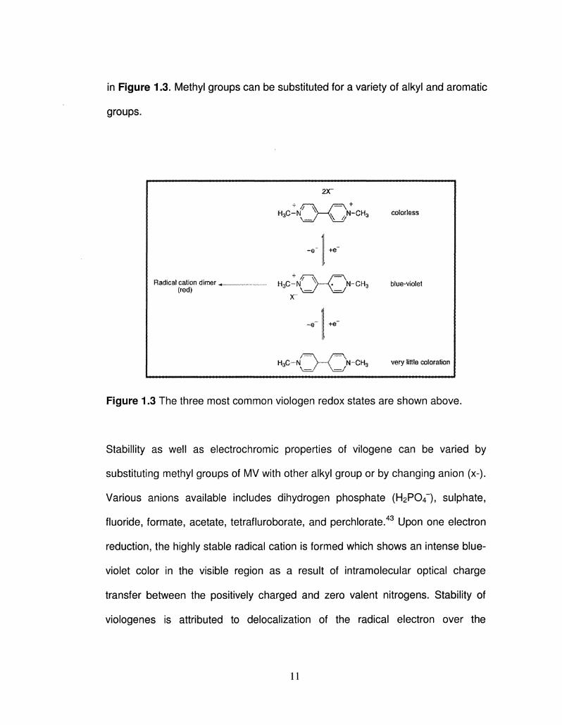
in Figure 1-3. Methyl groups can be substituted for a variety of alkyl and aromatic
groups.
Radical calion dimer ^„wwvv.......vv
(red)
2X~ 4 /r\ f=\ +
-e"
4 >r\ ..vvvv....vv H U f i — N > -
X"
«~e~
+@~
HQN-CH3
i
HgC~*N >—< N ~ G H 3
colorless
bfue-vfotet
very little cotor&to I
Figure 1.3 The three most common viologen redox states are shown above.
Stability as well as electrochromic properties of vilogene can be varied by
substituting methyl groups of MV with other alkyl group or by changing anion (x-).
Various anions available includes dihydrogen phosphate (H2P04~), sulphate,
fluoride, formate, acetate, tetrafluroborate, and perchlorate.43 Upon one electron
reduction, the highly stable radical cation is formed which shows an intense blue-
violet color in the visible region as a result of intramolecular optical charge
transfer between the positively charged and zero valent nitrogens. Stability of
viologenes is attributed to derealization of the radical electron over the
11
conjugated 7c-framework with the 1,1' substituents bearing some of the charge.
The color exhibited by the radical cation can be tuned to a certain extent by the
substitution of nitrogens with various alkyl and aryl groups. Specifically, 1,1'-
bis(4-cyanophenyl)-4,4'- bipyridilium exhibits a green-hued solution. The dinners
of the radical cations can also form; leading to the formation of a solution that is
more red in color.44 This phenomenon is most common in aqueous solution and
in non-aqueous solutions at low temperatures. The di-reduced viologens,
however, display low color absorption due to the lack of optical charge transfer or
internal transition corresponding to visible wavelengths region. Since both the
dication and radical cation of MV are soluble in aqueous electrolytes, its
coloration life span is finite. Upon one electro-reduction, the highly colored radical
cations are formed. However, once the electric potential is removed, the soluble
radical cation starts diffusing away from the electrode and diffuses into the bulk,
undergoing electron-transfer reactions with the equally soluble counter anion and
thus returning to the colorless dicationic form. This problem can be solved either
by using a semi-solid electrode such as poly(2-acrylamido-2-methylpropane-
sulfonic acid45 or by preparing viologens with longer alkyl chains. Semi-solid
electrodes slow the migration process of the radical cation into the bulk solution
while long alkyl chains result in insoluble radical cations that form well-adhered
films on the electrode surface. The most extensively studied viologen is 1,1'-di-
heptyl-4,4'-bipyridilium (heptyl viologen, HV) as the bromide salt. 46 The insoluble
crimson radical cation salt has been subsequently incorporated into devices that
12
have response times between 10 and 50 ms and lifetimes of >105 cycles
between the redox states.
A practical and cost-effective application of viologen's solution based
electrochromism is Gentex's automatic-dimming interior 'Night Vision Safety'
(NVS) mirrors. The device consists of a dual-coloring system where a
cathodically coloring viologen is in solution with an anodically coloring molecule.
The Optically transparent ITO-coated glass (with the conductive side facing
inward) is spaced micrometers apart from the reflective metallic surface with the
two electrochromic materials dissolved in a solvent.47 When the device is activate
(through a rear-facing photosensitive detector that senses the incident head light
from another vehicle) an applied potential reduces the viologen to the highly
colored radical cation that adheres to the ITO electrode provides night vision
functionality to device.
Moreover, this modern technology is also used in motorcycle visors, using a
material called electrochromic foil, which consists of thin oxide layers laminated
between two flexible polymer sheets. The foils are first coated with a transparent
electrically conducting layers followed by active electrochromic layers. The
lamination process includes a special ion-conducting electrolyte which makes it
possible to charge and discharge the electrochromic layers, thus getting them to
absorb or transfer visible light. This application is said to be able to greatly
reduce the amount of accidents caused by changing light conditions.
Furthermore, this technology is also used to manufacture windows that darken by
themselves upon changing light conditions. The windows have light sensors
13
installed in them and upon an increase in brightness from the outside, they will
transfer the light energy into electrical energy which will then be used to change
the structure of the electrochromic polymers in the windows, thus darkening the
windows in the process and preventing excess light from entering the structure.
Although, electrochromic materials based on transition metal oxides and
viologenes have received extensive research efforts and attempts toward
commercialization (some quite successfully), there remain drawbacks. These
include electrochromes that are solution-based, limiting application in devices,
such as some viologens, and transition-metal complexes, whereas other
materials have relatively slowswitching speeds, as with the metal oxides that
require anywhere from 30 s to several minutes to reach a full contrast,38 limiting
their application in devices that require a color change at shorter time frames.
Other drawbacks include lack of ease of processability to high surface area or
patterned films (as needed for windows and displays) and limit in range of colors
available. Through intensive synthetic efforts over the past 5-10 years,
conjugated electroactive polymers have come to address and remedy many of
these drawbacks, with efforts still underway, to allow for fully solution
processable, fast, and stable switching thin films that are available in colors that
span the entire visible region, switching to highly transmissive states. In that
sense, CP based electrochromics provides more potential.
14
1.2.3 Conjugated polymers
Electrochromism in conjugated polymers is particularly attractive from the
perspective that the visible absorption bands can be fine-tuned through organic
structure modifications. Controlling the electronic and steric environment by
substitution of aromatic monomers followed by polymerization results in
conjugated systems having large range of electrochromic responses. As an
outcome, electrochromic CPs have become the largest classe of electrochromic
materials studied. Most conjugated polymers are electrochromic in thin-film form,
with redox switching giving rise to new optical absorption bands in conjunction
with the transfer of electrons and counter anions.48 Among all the conjugated
polymers discussed previously, PTh, PPy, and PANI have attracted the most
attention as evidenced by the total volume of primary research articles and
reviews based on their study.49 PANI is the oldest of the conjugated polymers
with scientists referring to a material known as "aniline black". Its ability to form
processable, low cost conducting films exhibiting three distinctive color states,
depending on the extent of oxidation makes PANI as the most attractiove
electrochromic polymer.50"51 These polymer films exhibit polyelectrochromism
switching from a transparent, insulating leucoemeralidine state, to a
yellow/green, conducting emeralidine state, and finally to a blue/black
pernigraniline state.52Both electrochemical and chemical process can be used to
synthesize PANI, although the best films of PANI being prepared under constant
current conditions from aqueous acidic solutions.51
15
However, recently PANI has lost the attention of industrial and academic
groups due to the harsh acidic conditions required to make processable samples
as well as the possible formation of carcinogenic byproducts upon degradation.53
Fortunately, the formation of color states upon oxidation or reduction is a
property shared by most electractive conjugated polymers and as a result, other
heteroaromatic systems have essentially studied to replace PANI.
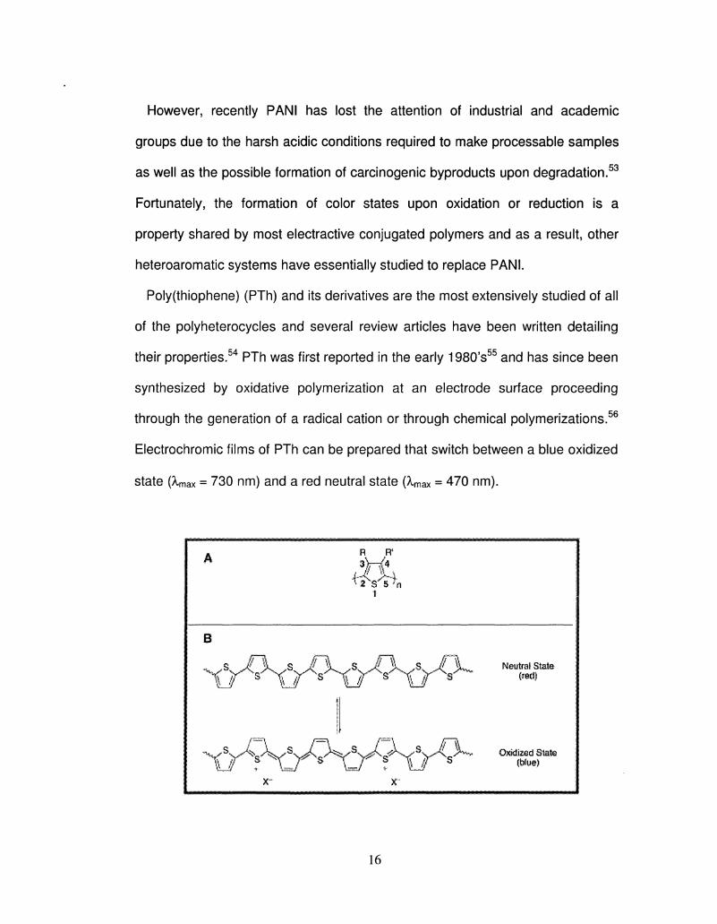
Poly(thiophene) (PTh) and its derivatives are the most extensively studied of all
of the polyheterocycles and several review articles have been written detailing
their properties.54 PTh was first reported in the early 1980's55 and has since been
synthesized by oxidative polymerization at an electrode surface proceeding
through the generation of a radical cation or through chemical polymerizations.56
Electrochromic films of PTh can be prepared that switch between a blue oxidized
state (max = 730 nm) and a red neutral state (Xmax = 470 nm).
R R* 3 H 4
i
B
\j \j \J s \J s
"xyV rvy\ s. A^^iX
Neutral State (fed)
Oxidized State (blue)
16
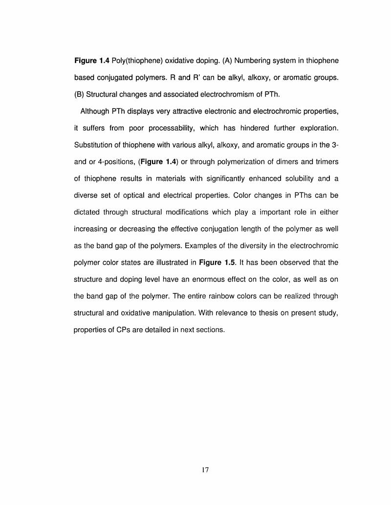
Figure 1.4 Poly(thiophene) oxidative doping. (A) Numbering system in thiophene
based conjugated polymers. R and R' can be alkyl, alkoxy, or aromatic groups.
(B) Structural changes and associated electrochromism of PTh.
Although PTh displays very attractive electronic and electrochromic properties,
it suffers from poor processability, which has hindered further exploration.
Substitution of thiophene with various alkyl, alkoxy, and aromatic groups in the 3-
and or 4-positions, (Figure 1.4) or through polymerization of dimers and trimers
of thiophene results in materials with significantly enhanced solubility and a
diverse set of optical and electrical properties. Color changes in PThs can be
dictated through structural modifications which play a important role in either
increasing or decreasing the effective conjugation length of the polymer as well
as the band gap of the polymers. Examples of the diversity in the electrochromic
polymer color states are illustrated in Figure 1.5. It has been observed that the
structure and doping level have an enormous effect on the color, as well as on
the band gap of the polymer. The entire rainbow colors can be realized through
structural and oxidative manipulation. With relevance to thesis on present study,
properties of CPs are detailed in next sections.
17
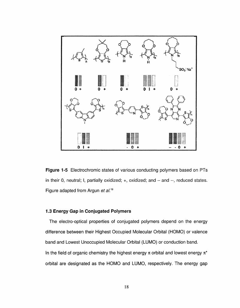
Figure 1-5 Electrochromic states of various conducting polymers based on PTs
in their 0, neutral; I, partially oxidized; +, oxidized; and - and --, reduced states.
Figure adapted from Argun et a/.19
1.3 Energy Gap in Conjugated Polymers
The electro-optical properties of conjugated polymers depend on the energy
difference between their Highest Occupied Molecular Orbital (HOMO) or valence
band and Lowest Unoccupied Molecular Orbital (LUMO) or conduction band.
In the field of organic chemistry the highest energy % orbital and lowest energy n*
orbital are designated as the HOMO and LUMO, respectively. The energy gap
18
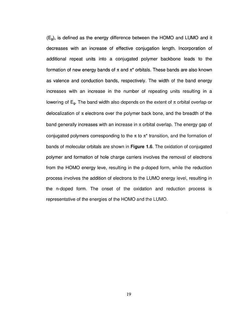
(Eg), is defined as the energy difference between the HOMO and LUMO and it
decreases with an increase of effective conjugation length. Incorporation of
additional repeat units into a conjugated polymer backbone leads to the
formation of new energy bands of n and n* orbitals. These bands are also known
as valence and conduction bands, respectively. The width of the band energy
increases with an increase in the number of repeating units resulting in a
lowering of Eg. The band width also depends on the extent of % orbital overlap or
derealization of n electrons over the polymer back bone, and the breadth of the
band generally increases with an increase in n orbital overlap. The energy gap of
conjugated polymers corresponding to the n to n* transition, and the formation of
bands of molecular orbitals are shown in Figure 1.6. The oxidation of conjugated
polymer and formation of hole charge carriers involves the removal of electrons
from the HOMO energy leve, resulting in the p-doped form, while the reduction
process involves the addition of electrons to the LUMO energy level, resulting in
the n-doped form. The onset of the oxidation and reduction process is
representative of the energies of the HOMO and the LUMO.
19
i -o c
LU
n= 1 2 3 4 5 6 a Figure 1.6 Energy band formation during polymerization of conjugated Monomer.
Generally there are two common methods for the determination of the energies
of the energy gap. One of the methods is electrochemistry, by which the
potentials for electron removal from the HOMO and electron injection into the
LUMO are determined. The energy difference between these two electron
transfer events is shown in Equation 1-2. The electrochemical method assumes
negligible intermolecular interactions.57"58
E~(Eox-Ered) + (S++S-){l- [ l - ( l / * 2 ) ] i 1-2
Where, Eox and Ered are the polymer oxidation and reduction potential onsets,
respectively; S+ and S" are the solvation energy of the positive or negative ions
20
minus the solvation energy of the neutral molecule, respectively; 81 and e2 are the
dielectric constants of the solution and the solid, respectively.
The second common method for determining energy gap of conjugated
polymer is through obtaining an electromagnetic spectrum of the neutral polymer,
in which the to 71* transition generally lies, within the lower energy near infrared
or higher energy visible region. Through this technique, the energy gap is defined
as the onset for the n to n* transition. Where spectra are not reported, it is useful
to report both the onset and the maximum for the absorption. In case of narrow
or sharp onset of absorbance peak, the wavelength at which it deviates from the
absorbance baseline (at the longer wavelength side) is generally taken as energy
gap. While in case of broad onset absorption peak, the energy gap is determined
by extrapolating the onset of the n to n* absorbance to the background
absorbance.
The Eg for conjugated polymers depends on several parameters involving both
intra and intermolecular interactions. Intramolecular parameters such as the
nature of the substituents and stereochemistry, and intermolecular parameters
such as interchain interactions may alter Eg and can be expressed as Equation
1-3.
Eg = E5r + Ee + ERes + ESub + Ein 1-3
where E5r, E0, ERes, ESub and Eint represent the energy related to bond length
alternation, coplanarity deviation, resonance, substituent and interchain
interactions, respectively.
21
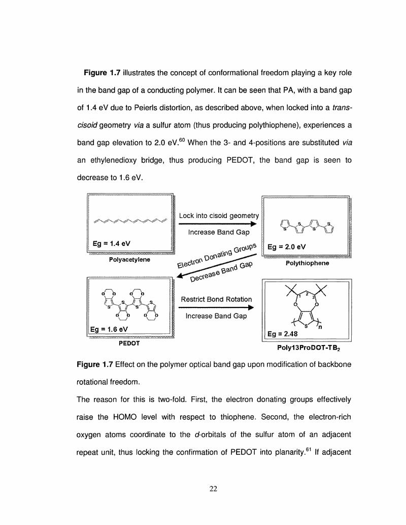
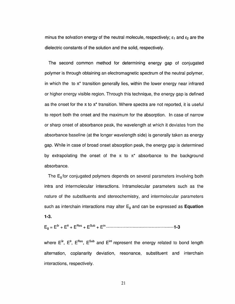
Figure 1.7 illustrates the concept of conformational freedom playing a key role
in the band gap of a conducting polymer. It can be seen that PA, with a band gap
of 1.4 eV due to Peierls distortion, as described above, when locked into a trans-
cisoid geometry via a sulfur atom (thus producing polythiophene), experiences a
band gap elevation to 2.0 eV.60 When the 3- and 4-positions are substituted via
an ethylenedioxy bridge, thus producing PEDOT, the band gap is seen to
decrease to 1.6 eV.
Lock into cisoid geometry
Increase Band Gap
G?oU9s
PoJyacetylene a^9
oO> ( A
E g - 1 . 6 e V
Polythiophene
Restrict Bond Rotation •
Increase Band Gap
PEDOT
Poly13ProDOT-TB2
Figure 1.7 Effect on the polymer optical band gap upon modification of backbone
rotational freedom.
The reason for this is two-fold. First, the electron donating groups effectively
raise the HOMO level with respect to thiophene. Second, the electron-rich
oxygen atoms coordinate to the d-orbitals of the sulfur atom of an adjacent
repeat unit, thus locking the confirmation of PEDOT into planarity.61 If adjacent
22
repeat units were to be conformationally restricted, a disruption of the TT-overlap
would occur, thus elevating the band gap, and will be the topic of discussion in
Chapter 3.
1.3.1 Bond Length Alternation:
E5r is the energy associated with bond length alternation, (BLA) which is related
to the difference between single and double bond length. BLA is also defined
quantitatively as 8r which is a measure of relative degree of aromatic and
quinonoid character in conjugated polymers. 5r > 0 or 8r < 0 indicates a
quinonoid or aromatic structure, respectively. The quinonoid form generally has a
lower Eg than the aromatic form.62 BLA is absent in poly(acetylene) due to two
degenerate ground states while the polyaromatic polymers such as
poly(thiophene), poly(pyrrole) and poly(p-phenylene) have nondegenerate forms,
aromatic and quinonoid, resulting in BLA as shown in Figure 1.8.63
Where X = S, NH, -CH=CH Figure 1.8 Aromatic and quinonoidal forms of conjugated polymers
1.3.2 Intrachain Interaction or Coplanarity Deviation
Ee, represents the energy related to the structure deviation from coplanarity,
and may arise from the interannular rotations of aromatic rings through the single
bond connecting them. Besides following the 4n + 2 n electron rule, coplanarity is
23
a prerequisite for a molecule to be aromatic (which means that there is a
derealization of n electrons). Rotational distortion limits the effective conjugation
length in oligothiophene, thereby increasing the Eg by Ee.64'66 When the
backbone of a conducting polymer is twisted out of planarity, the TT orbital overlap
decreases, resulting in a decrease of the effective conjugation length.'67 The
bandgap will be much higher in twisted polymers than in planar polymers. This
twisting leads to blue-shifted absorption Internal twisting has a dramatic effect on
conductivity and charge transport in the solid state. With increased twisting,
intrachain charge transport along polymer chains will decrease strongly. This
results in changes in interchain ordering which are highly dependent on the
individual chain conformations. Normally, polymer chains with a strongly twisted
backbone cannot order easily in the solid state. One exception is possible where
the twisting is regular leading to a formation of a helical structure.63'68 Figure 1.9
shows a series of different substituted polythiophenes with their emission
colors.64'69 Disubstitution of thiophene leads to a high degree of twisting arising
from steric repulsions between side chains on adjacent thiophenes, and also
steric interactions between side chains and the large sulfur atom. The polymers
then have shorter conjugation lengths, and their emission shifts to higher energy
(blue-shift) as the twisting increases.
24
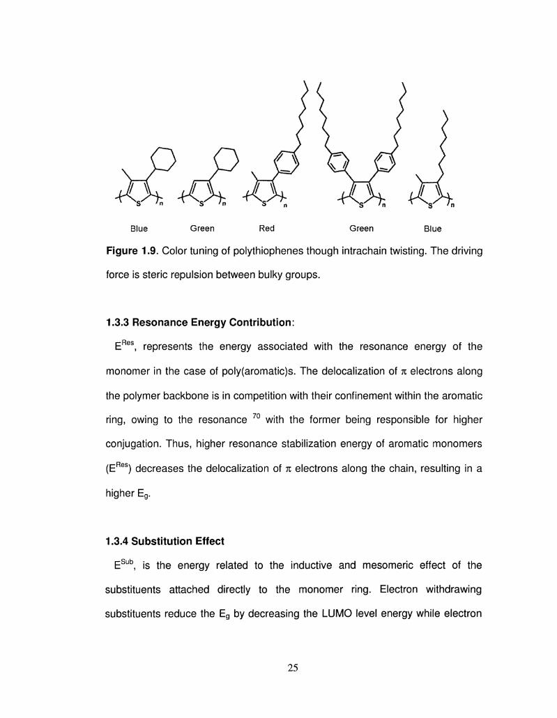
Blue Green Red Green Blue
Figure 1.9. Color tuning of polythiophenes though intrachain twisting. The driving
force is steric repulsion between bulky groups.
1.3.3 Resonance Energy Contribution:
ERes, represents the energy associated with the resonance energy of the
monomer in the case of poly(aromatic)s. The derealization of n electrons along
the polymer backbone is in competition with their confinement within the aromatic
ring, owing to the resonance 70 with the former being responsible for higher
conjugation. Thus, higher resonance stabilization energy of aromatic monomers
(ERes) decreases the derealization of n electrons along the chain, resulting in a
higher Eg.
1.3.4 Substitution Effect
ESub, is the energy related to the inductive and mesomeric effect of the
substituents attached directly to the monomer ring. Electron withdrawing
substituents reduce the Eg by decreasing the LUMO level energy while electron
25
donating substituents increase the energy of the HOMO level resulting in Eg
reduction (Figure 1.10). As substitution generally involves simple chemistry, this
is very popular method among chemists to modify or tune the Eg.
LUMP
e- withdrawing t J — — • * • E
substituent | a
y I
HOMO
Figure 1.10. Effect of Substituents (electron donating or electron withdrawing
substituents) on the Eg of Conjugated Polymers.
By introducing substituents on the conjugated polymer backbone, HOMO and
LUMO levels can be controlled precisely. By attaching electron donating or
electron withdrawing chains in direct conjugation with the conjugated backbone,
the HOMO and LUMO will be increased and decreased, respectively. Poly(3,4-
alkylenedioxythiophenes) (PXDOTs) are examples of a donor substituent effect.
By introducing the oxygen at the 3- and 4- positions of the thiophene, Tr-donation
of the lone pairs into the thiophene ring occurs. As a result, the HOMO level is
raised (-4.1 eV for neutral PEDOT, -5.3eV for P3HT) and the bandgap is
decreased (1.6 eV for PEDOT, 2.35eV for P3HT). PXDOTs are therefore much
easier to oxidize than polythiophenes and a bathochromic shift is observed in
their absorption spectrum (polymers are more blue). If electron-withdrawing
LUMO LUMO
E e* releasing 9 *
substituent
HOIVIO
HOMO
26
species are introduced in conjugation with the conjugated backbone, the result is
a lower LUMO level and a smaller bandgap. The oxygens have also an inductive
electron withdrawing effect but it is suppressed by the resonance donating effect.
But if a methylene spacer is introduced between the backbone and the oxygen,
then the resonance effect no longer occurs. The inductive effect is dominant and
the oxidation potential is raised. Compared to poly(thiophenes), it was shown that
poly(3- alkyloxymethylthiophenes) have 100mV higher oxidation potential,
corresponding to 0.1 eV lower HOMO levels.71 Another method for disruption of
the conjugated backbone is by altering its rotational freedom: either through
rotational restriction or liberation.
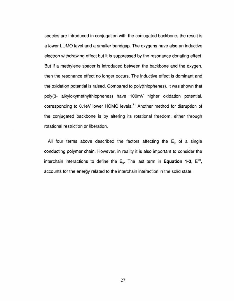
All four terms above described the factors affecting the Eg of a single
conducting polymer chain. However, in reality it is also important to consider the
interchain interactions to define the Eg. The last term in Equation 1-3, Eint,
accounts for the energy related to the interchain interaction in the solid state.
27
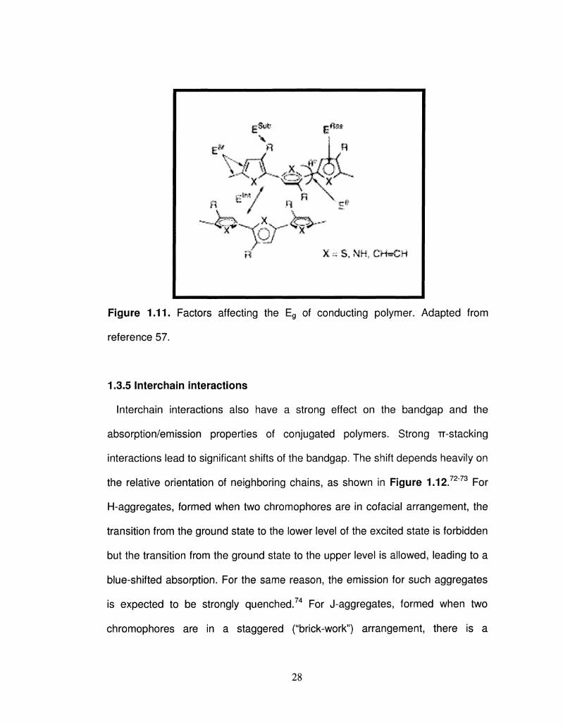
Figure 1.11. Factors affecting the Eg of conducting polymer. Adapted from
reference 57.
1.3.5 Interchain interactions
Interchain interactions also have a strong effect on the bandgap and the
absorption/emission properties of conjugated polymers. Strong TT-stacking
interactions lead to significant shifts of the bandgap, The shift depends heavily on
the relative orientation of neighboring chains, as shown in Figure 1.12.7273 For
H-aggregates, formed when two chromophores are in cofacial arrangement, the
transition from the ground state to the lower level of the excited state is forbidden
but the transition from the ground state to the upper level is allowed, leading to a
blue-shifted absorption. For the same reason, the emission for such aggregates
is expected to be strongly quenched.74 For J-aggregates, formed when two
chromophores are in a staggered ("brick-work") arrangement, there is a
28
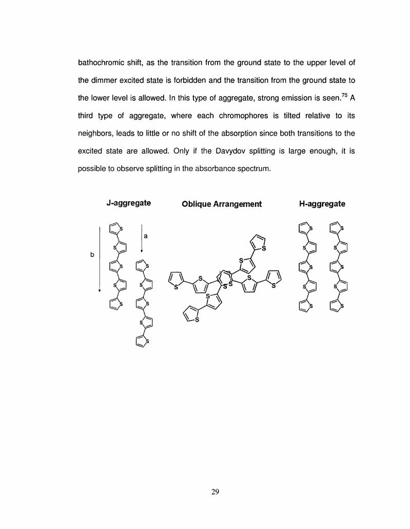
bathochromic shift, as the transition from the ground state to the upper level of
the dimmer excited state is forbidden and the transition from the ground state to
the lower level is allowed. In this type of aggregate, strong emission is seen.75 A
third type of aggregate, where each chromophores is tilted relative to its
neighbors, leads to little or no shift of the absorption since both transitions to the
excited state are allowed. Only if the Davydov splitting is large enough, it is
possible to observe splitting in the absorbance spectrum.
29
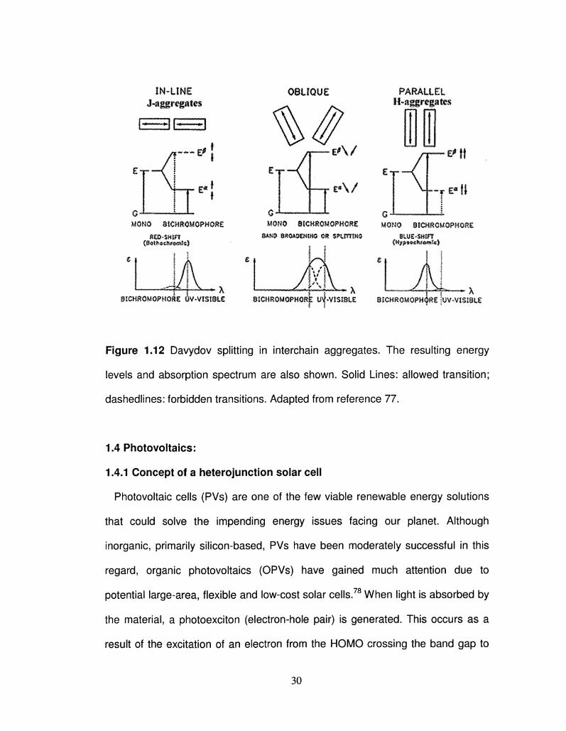
IN-LINE J-aggregat«
EE3EE3
OBLIQUE
MONO mumuomont nm-mm
(8«tlM«lmHntc)
PARALLEL H-aggregafes
MOMO dtCH&OMOPHORg HOMO 8f€H8OMOPK0f?£
mm mummm on mjrm& . 8Uf£*$Hlf¥ .
8ICHftOMQPHGi$g tW*V!$tSL€ 8!CMR0MQPH0ftjk U^VISISil SSCHROMOPH^RS iuV-VI$i8tE
Figure 1.12 Davydov splitting in interchain aggregates. The resulting energy
levels and absorption spectrum are also shown. Solid Lines: allowed transition;
dashedlines: forbidden transitions. Adapted from reference 77.
1.4 Photovoltaics:
1.4.1 Concept of a heterojunction solar cell
Photovoltaic cells (PVs) are one of the few viable renewable energy solutions
that could solve the impending energy issues facing our planet. Although
inorganic, primarily silicon-based, PVs have been moderately successful in this
regard, organic photovoltaics (OPVs) have gained much attention due to
potential large-area, flexible and low-cost solar cells.78 When light is absorbed by
the material, a photoexciton (electron-hole pair) is generated. This occurs as a
result of the excitation of an electron from the HOMO crossing the band gap to
30
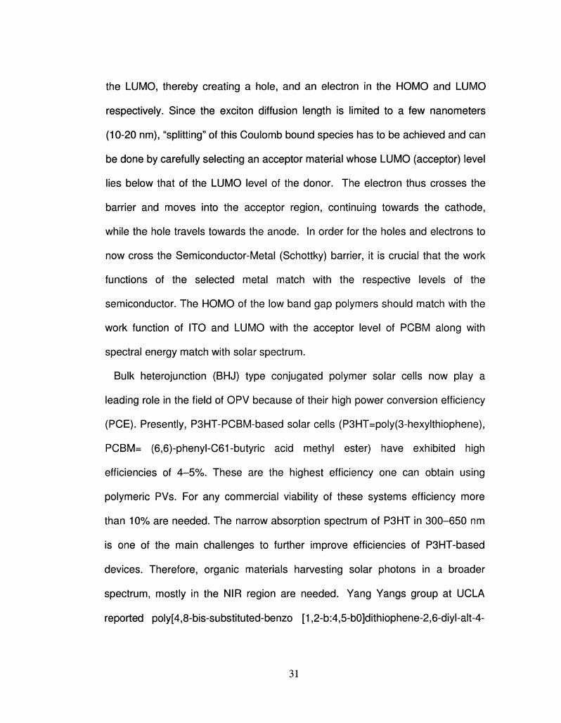
the LUMO, thereby creating a hole, and an electron in the HOMO and LUMO
respectively. Since the exciton diffusion length is limited to a few nanometers
(10-20 nm), "splitting" of this Coulomb bound species has to be achieved and can
be done by carefully selecting an acceptor material whose LUMO (acceptor) level
lies below that of the LUMO level of the donor. The electron thus crosses the
barrier and moves into the acceptor region, continuing towards the cathode,
while the hole travels towards the anode. In order for the holes and electrons to
now cross the Semiconductor-Metal (Schottky) barrier, it is crucial that the work
functions of the selected metal match with the respective levels of the
semiconductor. The HOMO of the low band gap polymers should match with the
work function of ITO and LUMO with the acceptor level of PCBM along with
spectral energy match with solar spectrum.
Bulk heterojunction (BHJ) type conjugated polymer solar cells now play a
leading role in the field of OPV because of their high power conversion efficiency
(PCE). Presently, P3HT-PCBM-based solar cells (P3HT=poly(3-hexylthiophene),
PCBM= (6,6)-phenyl-C61-butyric acid methyl ester) have exhibited high
efficiencies of 4-5%. These are the highest efficiency one can obtain using
polymeric PVs. For any commercial viability of these systems efficiency more
than 10% are needed. The narrow absorption spectrum of P3HT in 300-650 nm
is one of the main challenges to further improve efficiencies of P3HT-based
devices. Therefore, organic materials harvesting solar photons in a broader
spectrum, mostly in the NIR region are needed. Yang Yangs group at UCLA
reported poly[4,8-bis-substituted-benzo [1,2-b:4,5-b0]dithiophene-2,6-diyl-alt-4-
31
substituted-thieno[3, 4-b]thiophene-2,6-diyl] (PBDTTT), a low band gap CP with a
highest efficiecy (7.4%) reported till date79. Low band gap CPs exhibit spectrum
extending into NIR region. Moreover, the low band gap polymeric donor material
should have the following essential properties for the achievement of high
efficiency in device performance: adequate driving force for exciton dissociation,
high charge hole mobility, sufficiently high output and good miscibility with the
electron acceptor to form an interpenetrating network.79,80 Short circuit current
(Jsc), open circuit voltage (Voc), and fill factor (FF) are three main parameters to
characterize a OPV device. In order to get better Jsc, some low band gap
polymers (LGB) were synthesized and applied to the OPV devices. Among
several band gap tuning strategies, conjugated polymers with fused heterocyclic
rings has been known to yield polymers with very low band gaps.81
Polythieno[3,4-b]thiophene (PTT) is one kind of LBG polymer in which the fused
thiophene moieties can stabilize the quinoid structure of the backbone, thereby
reducing the band gap of the conjugated system which is used for OPV. 82 The
conversion of solar light into electrical power requires the generation of both
negative (electron) and positive (hole) charges and a driving force (a potential)
that extracts these charges to an external circuit. In organic semiconductors,
absorption of photons results in the formation of excitons. An exciton can be
considered as of a strongly bound electron-hole pair with a binding energy of
about 0.4 eV caused by Coulomb interaction. These excitons, carrying energy
but no net charge, have to diffuse to the dissociation sites where their charges
can be separated.83"85
32
The interface between suited donor (D) and acceptor (A) materials provides
dissociation sites. At the D/A interface, the energy difference in the electron
affinities and the ionization potentials of those two materials is large enough to
overcome the exciton binding energy. The holes reside in the material with the
lower ionization potential or HOMO, and electrons are captured in the material
with the higher electron affinity or lowest LUMO. After this charge transfer
process the electrons and holes are still bound by Coulomb interaction across
the D/A interface. After breaking the binding energy of this bound electron-hole
(e-h) pair, meaning the electron in the acceptor and the hole in the donor, the
then free electrons and holes travel through the acceptor and donor phase,
respectively, to the electrodes of the device.86"87To obtain efficient photon to
charge conversion, many different device architectures have been developed
such as single layer cells, double layer cells and bulk heterojunction blend cells.
The bulk heterojunction (BHJ) solar cells based on the intimate mixing of
conjugated polymers and fullerene derivatives are mostly used today. Because of
the larger D/A interface, which provides the exciton dissociation sites, a BHJ cell
is more efficient than the other above-mentioned structures.88"97 Therefore, state-
of-the-art organic solar cells are based on so-called donor/acceptor (D/A) bulk
heterojunction.
1.4.2 Fabrication aspects Polymer Solar Cells
33
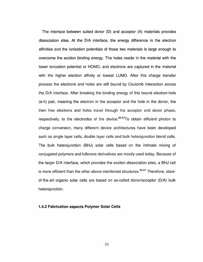
In Figure 1.13 the device structure is depicted, based on a blend of MDMO-PPV
and PCBM. The devices consist of active layere embeeded between two
electrodes i.e. anode and cathode.
In general, these electrodes of an organic solar cell must be conductive with
suited work function. This means that for extraction of the holes, the anode
should have the same work function (or deeper in energy) as the HOMO level of
the polymer used in the active layer. In ordes to match the work fuctions a thin
layer of poly(3,4-ethylene dioxythiophene) : polystryrenesulfonic acid
(PEDOT:PSS, H. C. Starck) is spin coated (about 50 nm) onto the anode that is
generally based on indium tin oxide (ITO) or gold (Au). The layer of PEDOT:PSS
stabilizes the work function of anode to about 5.1 eV. Furthermore, the PEDOT:
PSS improves the wetting between the electrode and the solution (blend of donor
and acceptor that are dissolved into chloroform or chlorobenzene) during
processing of the device. Additionally, PEDOT: PSS flattens the rough surface of
the ITO anode, which decreases the chance of shorting (anode in direct electrical
contact with the cathode) of the device. One of the two electrodes of the solar
cell has to be optically as transparent as possible, since the active layer is
processed between them. Therefore, indium tin oxide (ITO) is mostly used
because it is highly transparent and has high sheet conductivity for transporting
the holes extracted from the device under illumination. For the cathode of the
solar cell, a closed (-100 nm thick) layer of metals such as aluminum (Al) and
silver (Ag) is usually used. Electrically, the metallic cathode serves for transport
of the electrons extracted from the device under illumination. Optically, the
34
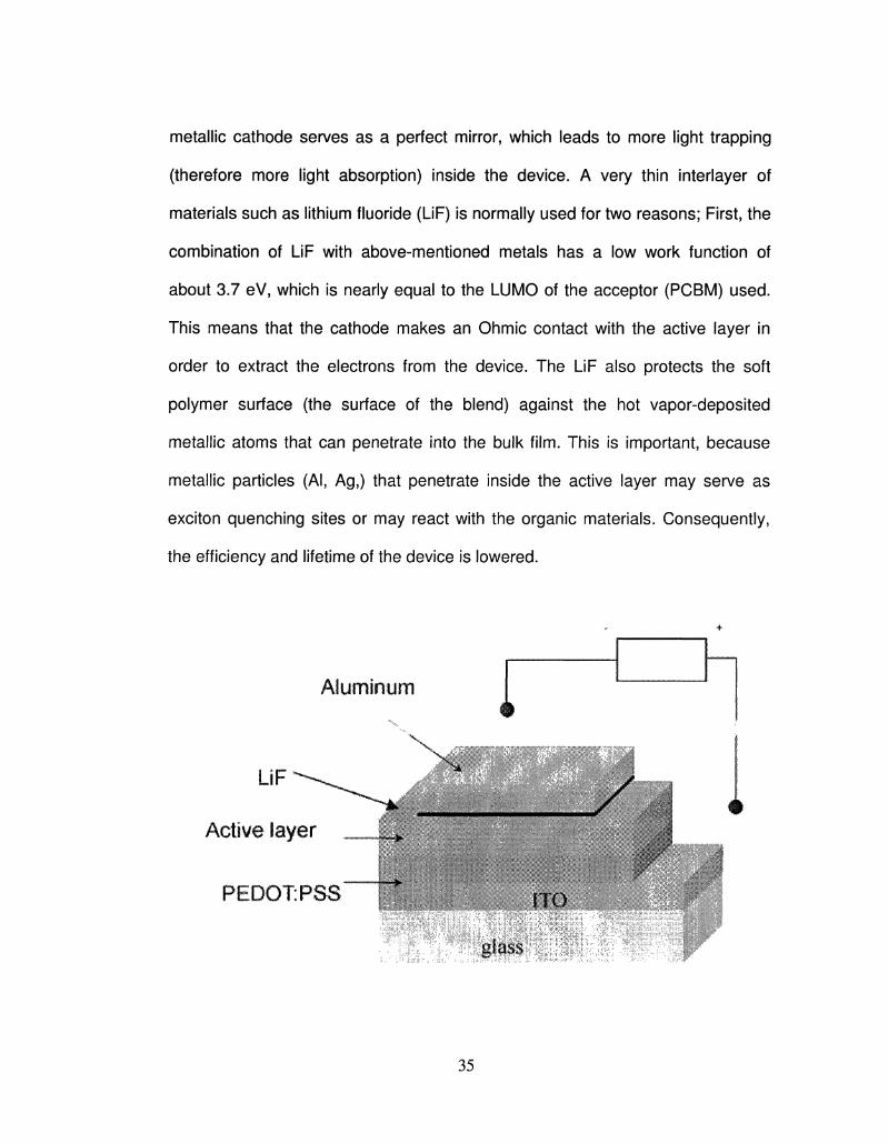
metallic cathode serves as a perfect mirror, which leads to more light trapping
(therefore more light absorption) inside the device. A very thin interlayer of
materials such as lithium fluoride (LiF) is normally used for two reasons; First, the
combination of LiF with above-mentioned metals has a low work function of
about 3.7 eV, which is nearly equal to the LUMO of the acceptor (PCBM) used.
This means that the cathode makes an Ohmic contact with the active layer in
order to extract the electrons from the device. The LiF also protects the soft
polymer surface (the surface of the blend) against the hot vapor-deposited
metallic atoms that can penetrate into the bulk film. This is important, because
metallic particles (Al, Ag,) that penetrate inside the active layer may serve as
exciton quenching sites or may react with the organic materials. Consequently,
the efficiency and lifetime of the device is lowered.
Aluminum
&&*
PEDOT" PSS
glass
35
Figure 1.13: The schematic structure and operation of an organic bulk
heterojunction solar cell. Adapted from reference 92.
1.4.3 Electrical Considerations
In order to measure the electrical performance of an organic solar cell , the
current density J vs. voltage V (J-V) characteristic has to be defined in dark and
under illumination by standard test condition (STC). The STC is 1000 W/m2
intensity, AM1.5 simulated solar spectrum and the substrate temperature equals
25 °C.
From such a measurement, the following parameters can be extracted: Open-
circuit voltage (V0c): the maximum voltage that a cell can produce under
illumination. At V0c the current-density (J) is zero. Short-circuit current (Jsc): the
current-density that a cell generates at zero applied voltage under illumination.
Photo-current (Jph): the difference between currents of the device in dark
and under illumination
Maximum Power (Pmax): The maximum power that a cell can produce is
when the product of the current-density (J) and voltage (V) is maximum.
Pmax = Vmax * Jmax
The Fill Factor (FF): a quantity that is defined as:
F F = ( V m a x * Jmax) / ( V o c * Jsc)
The power conversion efficiency (n): defined as the total power extracted
from the device under illumination divided by the total power of light:
H = Pout / Pin = Pmax / Plight = F F x ( V o c * Jsc) / Plight
36
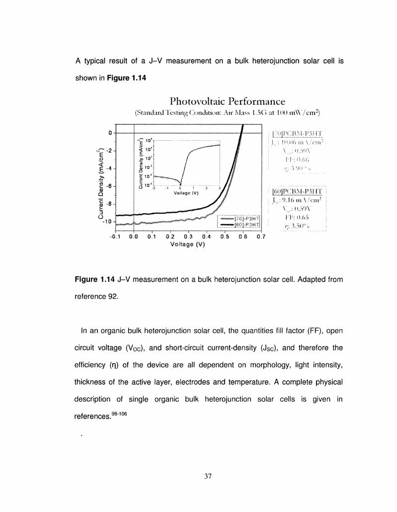
A typical result of a J-V measurement on a bulk heterojunction solar cell is
shown in Figure 1.14
Photovoltaic Performance (Standard Testing Condition: Air Mass 1..5G at 1.00 m W / c n r )
-0.1 0J3 0.1 0,2 0,3 0.4 o!s 0,6 0 J Voltage (V)
Figure 1.14 J-V measurement on a bulk heterojunction solar cell. Adapted from
reference 92.
In an organic bulk heterojunction solar cell, the quantities fill factor (FF), open
circuit voltage (Voc), and short-circuit current-density (Jsc), and therefore the
efficiency (q) of the device are all dependent on morphology, light intensity,
thickness of the active layer, electrodes and temperature. A complete physical
description of single organic bulk heterojunction solar cells is given in
references.98"106
37
1.4.4 Optical absorption
All the bulk heterojunction organic solar cells are based on blends of
conjugated polymers.98106 (MDMO-PPV, PFDTBT, RR-P3HT and PTBEHT) with
the fullerene derivative PCBM. Current polymeric materials being used have a
high band gap (>2.0 eV) and therefore absorb light in the mid to high energy
visible region of the solar flux, limiting the photon harvesting to 30%. Latest
developments inlcude increases in hole mobilities for P3HTs upon annealing,
and this has been attributed to the alignment and packing of the thiophene
chains. Morphological considerations have also been elaborately studied, and
investigations have shown a dramatic influence of microstructure and phase
separation on all aspects of OPV device performance. Optimization of the
morphology and charge mobilities have lead to the highest reported value for a
OPV device: 6% efficiency.107 This device was a tandem solar cell, in which a a
high band gap CP (P3HT) was used in conjuction with poly[2,6-(4,4-bis-(2-
ethylhexyl)-4H-cyclopenta[2,1-b;3,4-b,]dithiophene)-alt-4,7-(2,1,3
benzothiadiazole)] (PCPDTBT) separated by a thin Ti02 layer. Both the donors
(light harvesting dye), although complementing, absorb only in a narrow band of
the visble region and is thus unable to fully utilize the solar spectrum. Recently
benzo[1,2-b:4,5-b']dithiophene derivative PBDTTBT-PCBM system has been
reported, which exhibits efficiency of 7.73%. PBDTTBT has a band gap of 1.75
eV which is considerably higher than that of crystalline silicon cell.108
38
0 2
? LLii c
CM"
E
£ [oS
Loo^
Q | solar spectrum (AM 1.5-G, 1000 W/ms)
(5• y converted by crystalline silicon ceil
1100 nm - 1,1 eV » band gap of silicon
2400
Wavelength (nm)
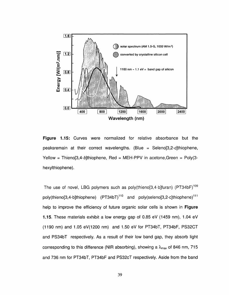
Figure 1.15: Curves were normalized for relative absorbance but the
peaksremain at their correct wavelengths. (Blue = Seleno[3,2-c]thiophene,
Yellow = Thieno[3,4-b]thiophene, Red = MEH-PPV in acetone,Green = Poly(3-
hexylthiophene).
The use of novel, LBG polymers such as poly(thieno[354-b]furan) (PT34bF)109
poly(thieno[3,4-b]thiophene) (PT34bT)110 and poly(seleno[352-c]thiophene)111
help to improve the efficiency of future organic solar cells is shown in Figure
1.15. These materials exhibit a low energy gap of 0.85 eV (1459 nm), 1.04 eV
(1190 nm) and 1.05 eV(1200 nm) and 1.50 eV for PT34bT, PT34bF5 PS32CT
and PS34bT respectively. As a result of their low band gap, they absorb light
corresponding to this difference (NIR absorbing), showing a Xmax of 846 nm, 715
and 736 nm for PT34bT, PT34bF and PS32cT respectively. Aside from the band
39
gap, they also offer a good match of the absolute energy levels with the other
materials in the device. The Highest Occupied Molecular Orbital (HOMO) of the
low band gap polymers agree with the work function of ITO. Their Lowest
Unoccupied Molecular Orbital (LUMO) matches with the acceptor level of PCBM.
This overlap is crucial to the function of a device.
1.5 Structure of this Thesis
The main objective of this work is the combination of fundamental studies on
the electrical and optical properties of conducting polymers from the 13ProDOT,
Thieno[3,4-b]furan, Thieno[3,4-jb]thiophene, 2-Alkyl-Thieno[3,4-ib]thiophene,
Seleno[3,4-b]thiophene and Seleno[3,2-c]thiophene class with more application-
driven studies of electrochomic devices as well as organic solar cells.
This research work was extremely exciting as it allowed probing of theoretical
deductions through practical application in devices. Multiple and content-varied
projects as well as several useful research collaborations made this work broad
in the sense that it covers a wide range of concepts defining the conducting
polymer.
The first part of the thesis work is mainly focused towards modifying the
electronic band-gap of conjugated polymers consisting of 1,3- disubstituted
ProDOT as one of the repeat units.Common derivatives of this molecule are
typically made at the beta position with respect to oxygen on the seven
membered ring. PProDOTs with methyl and benzyl substituents (beta position
with respect to oxygen) are two of the more successful due to their high contrast.
40
We have found that there is a much more substantial effect when PProDOT is
derivatized in the positions alpha to the oxygen. For example, two t-butyl groups
with each placed alpha to the oxygen in PProDOT incurs a 200 nm shift in the
lambda max (365 nm) compared to having two methyl groups with each placed
alpha to the oxygen. The dimethyl derivative is blue in color whereas the di-t-
butyl, dihexyl, diisopropyl is showing yellow, orange and red color respectively .
The polymer of this new derivative, P13ProDOT-TB2 and P13ProDOT-Hex2 is
organic-soluble and can be processed by a variety of solution methods, including
spray coating. Furthermore we have also studied some selenium based polymer
for electrochromic application. Poly(3,4-propylenedioxy)selenophenes
(PProDOS) is showing better optical contrast, stability and faster switching speed
as compared to their sulfur analogs.
The second part of the thesis contains the synthesis and characterization of
new low band gap polymers towards the organic photovoltaic applications.Low
band gap conducting polymers (CPs) have relatively low absorption in the visible
region, in their conducting states, making them promising candidates for optically
transparent electrode, hole- injection layer for light-emitting diodes and suitable
donor material for Photovoltaics. The monomer, Seleno[3,2-c]thiophene and
Seleno[3,4-jb]thiophene, were electrochemically and polymerized to produce
new low band gap conducting polymer, poly(Seleno[3,2-c]thiophene) (PS32cT)
and Poly(Seleno[3,4-fe]thiophene) (PS34bT), having a low band gap of 1.03 eV
and 1.50 eV respectively. Besides from the suitable energy gap, they also offer a
good match of the absolute energy levels with the other materials in the
41
photovoltaic device. The HOMO of the low band gap polymers agree with the
work function of ITO and LUMO matches with the acceptor level of PCBM. This
overlap is very important to the function of photovoltaic devices.
In a different approach we describe a new alternative route for the synthesis of
thieno[3,4-t)]thiophene, alkyl derivatives thereof, seleno[3,4-b]thiophene, and
thieno[3,4-b]furan made from inexpensive starting materials, such as thiophene-
2-carboxylic acid and furan-2-carboxylic acid. Such fused heterocycles are of
great interest for low band gap organic semiconductors and applications
including OLEDs, organic photovoltaic cells, and electrochromic applications.
42
1.6 References
1. Chiang, C. K.; Fincher, C. R.; Park, Y. W.; Heeger, A. J.; Shirakawa, H.; Louis,
E. J.; Gau, S. C; Macdiarmid, A. G. Physical Review Letters 1977, 39, 1098.
2. Shirakawa, H.; Louis, E. J.; Macdiarmid, A. G.; Chiang, C. K.; Heeger, A. J. J.
Chem. Soc. Comm. 1977, 578.
3. Letheby, H. J. Chem. Soc. 1862, 15, 161.
4. Noelting, E. Scientific and Industrial History of Aniline Black; J. Matheson: New
York, 1989.
5. Natta, G.; Mazzanti, G.; Corradini, P. Atti Accad. Lincei CI. Sci. Fis. Mat. Nat.
Rend. 1958, 25, 3.
6. Burt, F. B. J. Chem. Soc. 1910, 68, 105.
7. MacDiarmid, A. G. J. Am. Chem. Soc. 1976, 98, 3884.
8. Diaz, A. F.; Crowley, J.; Bargon, J.; Gardini, G. P.; Torrance, J. B. J.
Electroanal. C/7em.1981, 121, 355.
9. Tourillon, G.; Gamier, F. J.Electroanal. Chem. 1982, 135, 173.
10. MacDiarmid, A. G.; Chiang, J. C; Huang, W. S.; Humphrey, B. D.; Somasiri,
N. L. D. Molecular Crystals and Liquid Crystals 1985, 125, 309.
11. Skotheim, T. A.; Elsenbaumer, R. L.; Reynolds, J. R. Metal-Insulator
Transition in Conducting Polymers; 3rd ed.; Marcel Dekker: New York, 1998.
12. Roncali, J. Chem. Rev. 1992, 92, 711.
13. Roncali, J. Chem. Rev. 1997, 97, 173.
43
14. Dietrich, M.; Heinze, J.; Heywang, G.; Jonas, F. J. Electroanal. Chem. 1994,
369, 87.
15. Heywang, G.; Jonas, F. Adv. Mater. 1992, 4,116.
16. Groenendaal, B. L; Jonas, F.; Freitag, D.; Pielartzik, H.; Reynolds, J. R. Adv.
Mater. 2000, 12, 481.
17. Welsh, D. M.; Kumar, A.; Meijer, E. W.; Reynolds, J. R. Adv. Mater. 1999, 11,
1379.
18. Schottland, P.; Stephan, O.; Le Gall, P. Y.; Chevrot, C. J. De Chimie
Physique Et De Physico-Chimie Biologique 1998, 95, 1258.
19. (a) Kumar, A.; Welsh, D. M.; Morvant, M. C ; Piroux, F.; Abboud, K. A.;
Reynolds, J. R. Chem. Mater. 1998, 10, 896. (b) Cirpan, A.; Argun, A. A.;
Grenier, C. R. G.; Reeves, B. D.; Reynolds, J. R. J. Mater. Chem. 2003, 13, (10),
2422-2428.
20. Stephan, O.; Schottland, P.; Le Gall, P. Y.; Chevrot, C ; Mariet, C ; Carrier,
M. J. Electroanal. Chem. 1998, 443, 217.
21. Cutler, C. A.; Bouguettaya, M.; Reynolds, J. R. Adv. Mater. 2002, 14, 684.
22. Jonas, F.; Lerch, K. Kunststoffe-Plast Europe 1997, 87, 1401.
23. Schwendeman, I.; Hickman, R.; Zong, K.; Welsh, D. M.; Schottland, P.;
Sonmez, G.; Reynolds, J. R. Chem. Mater. 2002, 14, 3118.
24. Sapp, S. A.; Sotzing, G. A.; Reddinger, J. L; Reynolds, J. R. Adv. Mater.
1996, 8, 808.
25. Sapp, S. A.; Sotzing, G. A.; Reynolds, J. R. Chem. Mater. 1998, 10, 2101.
26. Irvin, D. J.; DuBois, C. J.; Reynolds, J. R. Chem. Comm. 1999, 2121.
44
27. (a) Hill, M. G.; Penneau, J. F.; Zinger, B.; Mann, K. R.; Miller, L. L. Chem.
Mater.1992, 4, 1106. (b) Bauerle, P.; Segelbacher, W.; Maier, A.; Mehring, M. J.
Am.Chem. Soc. 1993, 115, 10217. (c) Furukawa, Y. J. Phys. Chem. 1996, 100,
15644.
28. (a) Apperloo, J. J.; Janssen, R. A. J. Synth. Met. 1999, 101, 373. (b)
Apperloo, J. J.;Groenendaal, L; Verheyen, H.; Jayakannan, M.; Janssen, R. A.
J.; Dkhissi, A.; Beljonne, D.; Lassaroni, R.; Bredas, J.-L. Chem. Eur. J. 2002, 8,
2384.
29. (a) Piatt, J. R. J. Chem. Phys. 1961, 34, 862. (b) Monk, P. M. S.; Mortimer, R.
J.; Rooseinsky, D. R. Electrochromism: Fundamentals and Applications; VCH:
Weinheim, 1995. (c) Mortimer, R. J. Chem. Soc. Rev. 1997, 26, 147.
30. This has become an accepted term based on the work of Monk and
Mortimer, and is used in the literature to describe electrochromic polymers that
exhibit multiple colors. Multichromism is another term often used.
31. Mortimer, R. J. Electrochim. Acta 1999, 44, 2971.
32. Granqvist, C. G. Handbook of Inorganic Electrochromic Materials; Elsevier.
Amsterdam, 1995.
33. (a) Berzelius, J. J. Afhandlingar i fysik, kemi och mineralogy 1815, 4, 293. (b)
Berzelius, J. J. J. Chem. Phys. (Berlin) [also referred to as Schweigger's Journal]
1816, 16, 476.
34. Wohler, F. Ann. Phys. 1824, 2, 350.
35. Deb, S. K. Appl. Optics supp. 1969, 3, 192.
45
36. Zhang, J.-G.; Benson, D. K.; Tracy, C. E.; Deb, S. K.; Czandema, A. W.;
Bechinger, C. In Electrochromic Materials III; Ho, K. -C; Greenberg, C. B.;
MacArthur, D. M., Eds.; Electrochem. Soc. Proc. Ser.; Pennington: New Jersey,
1997, PV 96-24, p 251.
37. Hitchman, M. L. J. Electroanal. Chem. 1977, 85, 135.
38. (a) Gaughnan, B. W.; Crandall, R. S. In Display Devices; Pankove, J. I., Ed.;
Springer-Verlag: Berlin, 1980, Chapter 5. (b) Granqvist, C. G. Phys. Thin Films
1993, 17, 301. (c) Granqvist, C. G.; Lansaker, P. C; Mlyuka, N. R.; Niklasson,
G. A.; Avenda~no, E. Sol. Energy Mater. Sol. Cells 2009, 93, 2032.
39. Green, M. Chem. Ind. 1996, 17, 641.
40. This is the most common name for the bipyridylium salts from Michaelis, who
observed violet color formation upon one electron reduction of methyl viologen.
(a) Michaelis, L; Hill, E. S. J. Gen. Physiol. 1933, 16, 859. (b) Michaelis, L.
Chem. RevA935, 16, 243.
41. (a) Bird, C. L; Kuhn, A. T. Chem. Soc. Rev. 1981, 10, 49. (b) Monk, P. M. S.
TheViologens: Physicochemical Properties, Synthesis and Applications of the
Salts of 4,4'-Bipyridine; J. Wiley & Sons; Chichester, 1998.
42. (a) Summers, L. A. Adv. Heter. Chem. 1984, 35, 281. (b) Bard, A. J.; Ledwith,
A.;Shine, H. J. Adv. Phys. Org. Chem. 1976, 13, 155.
43. Van Dam, H. T.; Ponjee, J. J. J. Electrochem. Soc. 1974, 121,1555.
44. Monk, P. M. S.; Fairweather, R. D.; Duffy, J. A.; Ingram, M. D. J. Chem. Soc,
Perkin Trans. I11992, 2039
46
45.(a) Calvert, J. M.; Manuccia, T. J.; Nowak, R. J. J. Electrochem. Soc. 1986,
133, 951. (b) Sammells, A. F.; Pujare, N. U. J. Electrochem. Soc. 1986, 133,
1270.
46. Schoot, C. J.; Ponjee, J. J.; van Dam, H. T.; van Doom, R. A.; Bolwijn, P. J.
J. Appl.Phys. Lett. 1973, 23, 64.
47. Byker, H. In Electrochromic Materials II; Ho, K.-C; MacArthur, D. A., Eds.;
PV 94-2, Electrochem. Soc. Proc. Ser., Pennington: New Jersey, 1994, p 3.
48. (a) Evans, G. P. In Advances in Electrochemical Science and Engineering,
Gerischer.H.; Tobias, C. W., Eds.; VCH: Weinheim, 1990; Vol. 1, p 1. (b) Hyodo,
K. Electrochim. Acta 1994, 39, 265. (c) Higgins, S. J. Chem. Soc. flet/.1997, 26,
247.
49. (a) Toshima, N.; Hara, S. Prog. Polym. Sci. 1995, 20, 155. (b) Malhotra, B.;
Kumar, N.; Chandra, S. Prog. Polym. Sci. 1986, 12, 179. (c) Roncali, J. Chem.
Rev. 1992, 92, 711. (d) Roncali, J. J. Mater. Chem. 1999, 9, 1875. (e) Reddinger,
J. L; Reynolds, J. R. Adv. Polym. Sci. 1999, 145, 57.
50. Trivedi, d. C , In Handbook of Organic Conductive Molecules and Polymers,
Vol. 2,Nalwa, H. S., Ed.; Wiley: Chichester, UK, 1997, pp 505.
51. (a) Kobayashi, T.; Yoneyama, H.; Tamura, H. J. Electroanal. Chem. 1984,
177, 293. (b) Chinn, D.; DuBow, J.; Liess, M. Chem. Mater. 1995, 7, 1504.
52. (a) Rourke, F.; Crayston, J. A. J. Chem. Soc, Faraday Trans. 1993, 89, 295.
(b) Sherman, B. C ; Euler, W. B.; Force, R. R. J. Chem. Ec. 1994, 71, A94.
53. Lux, F. Farb & Lack 1998, 10, 93. 22
47
54. (a) Bauerle, P. Adv. Mater. 1993, 5, 879. (b) Roncali, J. Chem. Rev. 1997,
97,173 and references therein.
55. Yamamoto, T.; Sanechika, K.; Yamamoto, A. J. Polym. Sci., Polym Chem.
Ed. 1980,78,9.
56. McCullough, R. D. Adv. Mater. 1998, 10, 93
57.(a) Roncali, J. Chemical Reviews 1997, 97, 173, (b) Parker, V. D., Energetics
of electrode reactions. II. The relationship between redox potentials, ionization
potentials, electron affinities, and solvation energies of aromatic hydrocarbons, J.
Am. Chem. Soc, 1976, 98, 98.
58. Lyons, L. E.5 Energy gaps in organic semiconductors derived from
electrochemical data, Aust. J. Chem. 1980, 33, 1717.
59. Loutfy, R. O., and Cheng, Y. C , Investigation of energy levels due to
transition metal impurities in metal-free phthalocyanine, J. Chem. Phys. 1980, 73,
2902.
60. Roncali, J. Chem. Rev. 1992, 92, 4, 711.
61. Roncali, J.; Blanchard, P.; Frere, P. J. Mater. Chem. 2005, 15, 1589.
62. (a)Bredas, J. L, Street, G. B., Themans, B., Andre, J. M. J. Chem. Phys.
1985, 83, 1323. (b) Bredas, J. L, Relationship between band gap and bond
length alternation in organic conjugated polymers, J. Chem. Phys. 1985, 82,
3808.
63. (a) Kobayashi, N., Sasaki, S., Abe, M., Watanabe, S., Fukumoto, H.,
Yamamoto, T. Macromolecules 2004, 37, 7986. (b) Lee, Y-S., and Kertesz, M.,
48
The effect of heteroatomic substitutions on the band gap of polyacetylene and
polyparaphenylene derivatives, J. Chem. Phys. 1988, 88, 2609.
64. (a) Andersson, M. R., Thomas, O., Mammo, W., Svensson, M., Theander,
M., Inganas, O. J. Mater. Chem. 1999, 9, 1933.
65. (a) Hoffmann, K. J.; Bakken, E.; Samuelsen, E. J.; Carlsen, P. H. J. Synth.
Met. 2000, 113, 1-2, 39. (b) Guay, J.; Kasai, P.; Diaz, A.; Wu, Ruilian; Tour,
James M., and Dao, Le H., Chain-length dependence of electrochemical and
electronic properties of neutral and oxidized soluble .alpha.,.alpha.-coupled
thiophene oligomers, Chem. Mater.,1992, 4,1097.
66. (a) Hoffmann, K. J.; Graskopf, A. L; Samulesen, E. J.; Carlsen, P. H. J.
Synth. Met. 2000, 113, 1-2, 89. (b) Sato, M., and Hiroi, M., Synthesis and
properties of hexyl-substituted oligothiophenes, Synth. Met, 1995, 71, 2085.
67. Hoffmann, K. J.; Knudsen, L; Samuelsen, E. J.; Carlsen, P. H. J. Synth. Met.
2000, 114,2,161.
68. Hoffmann, K. J.; Samuelsen, E. J.; Carlsen, P. H. J. Synth. Met. 2000, 113,
7-2,161.
69. Hoffmann, K. J.; Samuelsen, E. J.; Carlsen, P. H. J. Synth. Met. 2000, 114, 2,
167.
70. Rajca, A.; Miyasaka, M.; Pink, M.; Wang, H.; Rajca, S. J. Am. Chem. Soc.
2004,126, (46), 15211.
71. (a) Lemaire, M., Garreau, R., Roncali, J., Delabouglise, D., Youssoufi, H. K.,
Gamier, F. J. Chem. 1989, 13, 863. (b) Gaupp, C. L; Reynolds, J. R.
Macromolecules 2003, 36, 17, 6305.
49
73. Witker, D.; Reynolds, J. R. Macromolecules 2005, 38, 18, 7636-7644.
73. Siddiqui, S., Spano, F. C. Chem. Phys. Lett. 1999, 308, 99; Cornil, J.,
Beljonne, D., Calbert, J. P., Bredas, J. L. Adv. Mater. 2001, 13, 1053.
74. Kasha, M., Rawls, H. R., El-Bayoumi, M. A. PureAppi Chem. 1965, 7 7, 371.
75. (a) Cornil, J., dos Santos, D. A., Crispin, X., Silbey, R., Bredas, J. L. J. Am.
Chem.Soc. 1998, 720, 1289; (b) Bredas, J. L, Cornil, J., Beljonne, D., dos
Santos.D., Shuai, Z. G. Ace. Chem. Res. 1999, 32, 267; (c) Cornil, J., dos
Santos, D.A., Silbey, R., Bredas, J. L. Synthetic Metals 1999, 707, 492.
76. Wurthner, F., Thalacker, C , Diele, S., Tschierske, C. Chem.-Eur. J. 2001, 7,
2245.
77. Lighthner, D. A., Gurst J. E.. Organic Conformational Analysis and
Stereochemistry from Circular Dichroism Spectroscopy, Wiley-VCH; New York,
2000.
78.a) Yu, G.; Gao, J.; Hummelen, J. C ; Wudl, F; Heeger, H. J. Science 1995,
270, 1789; b) Kim, J. Y.; Lee, K.; Coates, N. E.; Moses, D.; Nguyen, T. Q.;
Dante, M.; Heeger, A. J. Science 2007, 317, 222; c) Brabec, J.; Sariciftci, N. S.;
Hummelen, J. C. Adv. Funct. Mater. 2001,7 7, 15.
79. (a) Roncali, J. Macromol. Rapid Commun. 2007, 28, 1761. (b) Coakley, K.
M.; McGehee, M. D. Chem. Mater., 2004, 16, 4533.
80. Roncali, J. Chem. Rev., 1997, 97, 173.
81. Pomerantz, M. in Handbook of Conducting Polymer, Marcel Dekker, New
York 1998, pp. 277-310.
50
82. (a) Yao.Y.; Liang.Y.; Shrotriya, V.; Xiao, S.; Yu, L.; Yang Y. . Adv. Mater.
2007, 19, 3979. (b) Liang, Y.; Feng, D.; Guo, J.; Szarko, J. M.; Ray, C; Chen, L
X.; Yu, L.Macromolecules, 2009, 42, 1091.
83. Barth, S.; Bassler, H. Phys. Rev. Lett. 1997, 79, 4445.
84. Dacosta, P. G.; Conwell, E. M. Phys. Rev. B1993, 48, 1993.
85. Marks, R. N.; Halls, J. J. M.; Bradley, D. C; Friend, R. H.; Holmes, A. B. J.
Phys.Cond. Mat. 1994, 6, 1379.
86. Braun, C. L J. Chem. Phys. 1984, 80, 4157.
87. Goliber, E.; Pettstein, J. H. J. Chem. Phys. 1984, 80, 4162.
88. Kallmann, H.; Pope, M. J. Chem. Phys. 1959, 30, 585.
89. Tang, C. W. Appl. Phys. Lett. 1986, 48, 183.
90. Halls, J. J. M.; Walsh, C. A.; Greenham, N. C; Marseglia, E. A.; Friend, R.
H.; Morahi, S. C; Holmes, A. B. Nature 1995, 376, 498.
91. Yu, G.; Gao, J.; Hummelen, J. C; Wudl, F.; Heeger, A. J. Science 1995, 270,
1789.
92. Brabec, C. J.; Sariciftci, N. S.; Hummelen, J. C; Adv. Funct. Mater. 2001,
7 7,15.
93. Hummelen, J. C; Knight, B. W.; Lepeq, F.; Wudl, F.; Yao, J.; Wilkins, C. L. J.
Org. Chem. 1995, 60, 532.
94. Mihailetchi, V. D.; Van Duren, J. K. J.; Blom, P. W. M.; Hummelen, J. C;
Janssen, R. A. J.; Kroon, J. M.; Rispens, M. T.; Verhees, W. J. H.; Wienk, M. M.
Adv. Funct.Mater. 2003, 13, 43.
51
95. Mihailetchi, V. D.; Blom, P. W. M.; Hummelen, J. C; Rispens, M. T. J. Appl.
Phys.2003, 94, 6849.
96. Mihailetchi, V. D., Koster, L J. A.; Hummelen, J. C; Blom, P. W. M. Phys.
Rev.Lett. 2004, 93, 216601. 123
97. Mihailetchi, V. D., Koster, L. J. A.; Hummelen, J. C; Blom, P. W. M. Phys.
Rev.Lett. 2004, 85, 970.
98. Melzer.C; Koop, E. J.; Mihailetchi, V. D.; Blom, P. W. M. Adv. Fund. Mater.
2004, 14, 865.
99. Mihailetchi, V. D.; Wildeman, J.; Blom, P. W. M. Phys. Rev. Lett. 2005, 94,
126602.
100. Koster, L. J. A.; Mihailetchi, V. D.; Xie, H. X.; Blom, P. W. M. Appl. Phys.
Lett. 2005, 87, 203502.
101 Koster, L. J. A.; Mihailetchi, V. D.; Ramaker, R.; Blom, P. W. M. Appl. Phys.
Lett. 2005, 86, 123509.
102. (a) Thomas, C.A. Donor-Acceptor Methods For Band Gap Reduction in
Conjugated Polymers: The Role of Electron Rich Donor Heterocyles, University
of Florida, Ph. D. Dissertation, 2001; (b) Dubois, C. J., Donor-Acceptor Methods
for Band Gap Control in Conjugated Polymers, University of Florida, Ph. D.
Dissertation, 2003.; (c) Thompson, B. C. Variable Band-Gap Poly(3,4-
Alkylenedioxythiophene)-Based Polymers for Photovoltaic and Electrochromic
Applications, University of Florida, Ph. D. Dissertation, 2005.
103. N, Hoppe, N. Arnold, N. S. Sariciftci, D. Meissner, Solar Energy Mater. &
SolarCells 2003, 80, 105.
52
104. C. J. Brabec, A. Gravino, D. Meissner, N. S. Sariciftci, M. T. Rispens, L.
Sanchez, J. C. Hummelen, T. Fromherz, Thin Solid Films 2002, 403, 368.
105. I. Riedel, J. Parisi, V. Dyakonov, L. Lutsen, D. Vanderzande, J. C.
Hummelen,/Wi/. Fund Mater. 2004, 14, 38.
106. P. W. M. Blom, V. D. Mihailetchi, L J. A. Koster, and D. E. Markov, Adv.
Mater. 2007, 19, 1551.
107. Chen, H. Y.; Hou, J. H.; Zhang, S. Q.; Liang, Y. Y.; Yang, G. W.; Yang, Y.;
Yu, L. P.; Wu, Y.; Li, G. Nat. Photonics 2009, 3, 649
108. Huo, L; Hou, J.; Zhang, S.; Chen, H. Y.; Yang. Y. Angew. Chem. Int. Ed.
2010,45,1500.
109. (a) Kumar, A.; Buyukmumcu, Z.; Sotzing, G.A. Macromolecules 2006, 39,
2723. (b) Kumar, A.; Bokria, J.; Dey, T.; Buyukmumcu, Z.; Sotzing, G.A.
Macromolecules 2008, 341, 7098.
110. (a) Lee, K.; Sotzing, G. A. Macromolecules 2001, 34, 5746-5747. (b)
Sotzing, G. A.; Lee, K.Macromolecules 2002, 35, 7281-7286.
111. (a) Dey, T.; Navarathne, D.; Invemale, M. A.; Berghorn I. D.; Sotzing, G.A.
Tetrahedron Letter, 2010 (in press), (b) Dey, T.; Invemale, M. A.; Buyukmumcu,
Z.; Sotzing, G.A. Macromolecules ( in submission).
53
CHAPTER 2
EXPERIMENTAL
The work reported in this thesis involves the syntheses of new electroactive
monomers using multi-step organic synthesis and converting them into
conducting polymers by conventional electrochemical polymerizations or
chemical polymerizations.
All chemicals were purchased from Aldrich Chemicals or ACROS and used as
received unless mentioned otherwise. The monomer/polymer structure and purity
were determined by 1H-NMR, 13C-NMR, 77 Se-NMR5 elemental
analysis,GCMS, FTIR and GPC thus instrumentation details are only reported
for those techniques. Melting point measurements were also performed on solids
for complete characterization. For the deeper understanding of the newly
synthesized materials, specialized analytical techniques such as cyclic
voltammetry, square-wave voltammetry, electrochemical quartz crystal
microbalance, and in-situ spectroelectrochemistry are required.
54
2.1 Materials
All reactions were carried out in flame- dried flasks under inert atmosphere
unless stated otherwise. Furan-2-carboxylic Acid, Thiophene-2-carboxylic acid,
lithium aluminium hydride (LiAIH4), phosphorous tribromide, sodium sulfide,
selenium powder, 2,3-Dichloro-5,6-dicyano-p-benzoquinone (DDQ), Iron (III)
chloride, Antimony (V) chloride, tetrabutylammonium bromide, hydrazine hydrate
and n-pentane were purchased from Fisher/Acros and used as such. Butyl
Lithium (BuLi) (2.5 M in hexanes), Ethyl magnesium bromide (1M solution in
THF), hexyl magnesium, pentane-2,4-diol, 3,3-dimethylbutan-2-one,
pivalaldehyde, 3-methylbutan-2-one, isobutyraldehyde, Diisobutylaluminium
hydride (DIBAL-H), 2,3-dimethoxybuta-1,3-diene, hydroquinone were used as
received from Aldrich. Acetonitrile and methylene chloride were purchased from
FISHER, and dried over calcium hydride (anhydrous) before use. Toluene was
purchased from FISHER and dried over sodium under nitrogen atmosphere
before use. THF (FISHER) was dried over potassium/ benzophenone ketyl under
nitrogen atmosphere, and distilled before use. Tetrahydrofuran (THF) was filtered
through 0.45 |iim PTFE whatmann filter paper prior to use for GPC
characterization. ITO-glass (unpolished float glass) (7 X 50 X 0.7 mm) with Rs =
5-15 CI was purchased from Delta Technologies Inc. for in-situ
spectroelectrochemistry.
55
2.2 Instrumentation
A HP 5890 series II GC-MS and Nicolet Magna-IR 560 FT-IR spectrometer
were used for the characterizon of monomers and polymers. A Bruker 400 FT-
NMR spectrometer was used to record 1H, 13C and 77Se nuclear magnetic
resonance (NMR) spectra using tetramethylsilane (TMS) as a reference.
Chemical shifts are reported as ppm downfield from TMS, and peak multiplicities
are reported as: br = broad signal, s = singlet, d = doublet, t = triplet, q = quartet,
dd = doublet of doublets, and m = multiplet. A CH instrument 400 potentiostat
was used for all electrochemical studies, Film thicknesses were obtained using a
Veeco DekTak mechanical profilometer. Spectroelectrochemistry was carried out
with a Varian Cary 5000 UV-Vis-NIR spectrophotometer with a 150 mm DRA
Integrating Sphere and Color software. Color data were calculated using a 10
degree standard observer angle, a measurement range of 360 nm to 860 nm in 1
nm intervals, and a standard D65 illuminant. Number-average molecular weight
and polydispersity index (PDI) of homopolymers and copolymers were
determined by using Waters 150-C plus gel permeation chromatograph (GPC)
and monodisperse polystyrene as a standard. GPC is equipped with UV/Vis,
refractive index, and evaporative light scattering detectors. Thermal properties of
polymers were measured using TA Instruments DSC Q-100, and TA Instruments
TGA Q-500.
56
2.3 Electrochemistry for Organic Polymer Chemists
General Experimental Preparation and Setup
There are several different methods which can be utilized to carry out the
electropolymerization of thiophene and pyrrole-based monomers including cyclic
voltammetry, constantcurrent, and constant potential methods.1
For all the electrochemical experiments the monomer is dissolved in a high
dielectric constant solvent (such as acetonitrile or propylene carbonate). It is
essential that the solvent be electrochemically inert (meaning that it will not
undergo electrochemical reactions itself within the potential window being used
for the experiment) and non-nucleophilic. In addition to the solvent, a supporting
electrolyte (such as the tetrabutylammonium (TBA+) and lithium (Li+) salts of
perchlorate, tosylate, tetrafluoroborate, and hexafluorophosphate) is also vital to
help current pass through the solution and to compensate charges that form on
the polymer during the redox process. Specifically, tetrabutylammonium
hexafluorophosphate (TBAPF6) was used for many of the electrochemical
experiments. For all of the electrochemical methods discussed within this
dissertation, an electrolyte concentration of 10 mM in solvent is used. It is
important to note that all solutions should be prepared from dry solvents as well
as pure electrolyte and monomer. Electrolyte and monomer purity is often
ignored, but can be a significant contributor to observed polymer
electrochemical properties. In addition, to minimize experimental error, fresh
solutions should be prepared at the start of the day's experiments because of the
high reactive nature of electron-rich heterocyclic monomers. Each polymerization
57
method discussed within this chapter utilizes a standard three-electrode setup
consists of a working electrode (i.e. Pt or ITO-coated glass), a counter electrode
(typically a Pt wire/ Pt Flag), and a reference electrode (in this dissertation a
Ag/Ag+ reference was utilized), connected to a potentiostat.2 The monomer
solution is placed inside the electrochemical cell in such a way that each
electrode is submerged properly into the solution. Prior to any experiment, the
solution is carefully sparged by bubbling with argon/nitrogen to remove incipient
oxygen. After through sparging, the needle attached to the argon line is removed
from solution and placed just above the surface of the liquid to maintain an inert
atmosphere blanket. By following this protocol, reproducible electrochemical data
can be obtained, or at the very least, an experimental inconsistency can be
minimized.
2.4 Techniques
2.4.1 Cyclicvoltammetry
Cyclic voltammetry (CV) is the most convenient and simple method for initial
studies on electrochemically polymerizeable compounds. In a typical CV
experiment, the potential is swept at a constant rate, while the current is
monitored. Commonly, a dilute monomer solution (c.a. 10 mmol in 0.1 M
electrolyte solution in acetonitrile, propylene carbonate, etc.) is used. Typical
electrochemical cell consists of a counter, working, and reference electrode.
Three electrodes system is used for the better control of the potential. However,
two electrodes cell can be used without a reference if exact potential values are
58
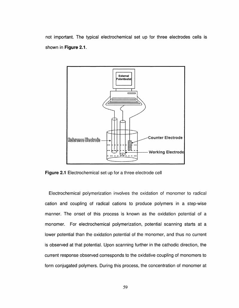
not important. The typical electrochemical set up for three electrodes cells is
shown in Figure 2.1.
Figure 2.1 Electrochemical set up for a three electrode cell
Electrochemical polymerization involves the oxidation of monomer to radical
cation and coupling of radical cations to produce polymers in a step-wise
manner. The onset of this process is known as the oxidation potential of a
monomer. For electrochemical polymerization, potential scanning starts at a
lower potential than the oxidation potential of the monomer, and thus no current
is observed at that potential. Upon scanning further in the cathodic direction, the
current response observed corresponds to the oxidative coupling of monomers to
form conjugated polymers. During this process, the concentration of monomer at
59
electrode interface begins to decrease over time. This is compensated by the
diffusion of monomer from solution towards the electrode, and a diffusion limited
peak is observed on going even further in the cathodic direction. By reversing the
scan in the anodic direction, a broad current response is observed corresponding
to the reduction of conjugated polymer deposited onto the working electrode. The
starting point is a reducing value with the potential being swept to positive
potentials until monomer oxidation and polymerization occurs. Monomer
oxidation is observed with a steep increase in current, followed by a peak, which
is referred to as the peak monomer potential (Ep,m). Following the Ep,m, a sharp
decrease in current is observed and shortly afterwards (typically abou 100 - 200
mV) the scan is reversed back to the starting potential. On the return scan, two
features are clearly visible and are indicative of the deposition of electroactive
species. The first feature is commonly known as the nucleation loop, where the
return scan after monomer oxidation crosses the anodic wave, and is exclusive
to conjugated polymers and metal deposition. Nucleation loops arise due to the
formation of electroactive polymer onto the working electrode, increasing its
electrically conducting surface area. The second feature has a maximum current
response at -0.2 V in Figure 2.2A and is attributed to reduction of the polymer
that was deposited onto the working electrode.
(A)
60
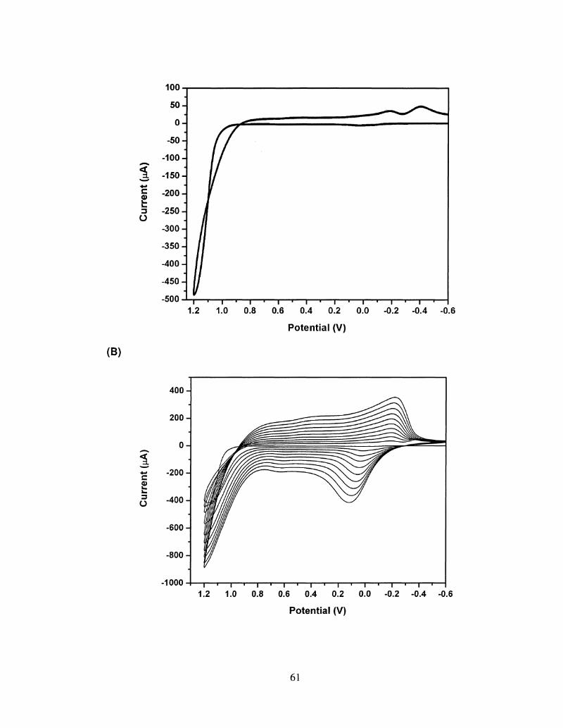
100
c
o
0.6 0.4 0.2 0.0
Potential (V)
-0.6
(B)
<
c
400 J
200-J
0
-200-
-400-
-600-
-800-J
-1000 — I — i — | — i — | — i — | — i — \ — i — | — i — | — i — | — i — | — i -
1.2 1.0 0.8 0.6 0.4 0.2 0.0 -0.2 -0.4 -0.6
Potential (V)
61
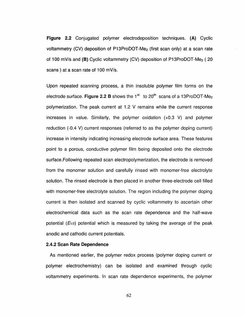
Figure 2.2 Conjugated polymer electrodeposition techniques. (A) Cyclic
voltammetry (CV) deposition of P13ProDOT-Me2 (first scan only) at a scan rate
of 100 mV/s and (B) Cyclic voltammetry (CV) deposition of P13ProDOT-Me2 ( 20
scans ) at a scan rate of 100 mV/s.
Upon repeated scanning process, a thin insoluble polymer film forms on the
electrode surface. Figure 2.2 B shows the 1st to 20th scans of a 13ProDOT-Me2
polymerization. The peak current at 1.2 V remains while the current response
increases in value. Similarly, the polymer oxidation (+0.3 V) and polymer
reduction (-0.4 V) current responses (referred to as the polymer doping current)
increase in intensity indicating increasing electrode surface area. These features
point to a porous, conductive polymer film being deposited onto the electrode
surface.Following repeated scan electropolymerization, the electrode is removed
from the monomer solution and carefully rinsed with monomer-free electrolyte
solution. The rinsed electrode is then placed in another three-electrode cell filled
with monomer-free electrolyte solution. The region including the polymer doping
current is then isolated and scanned by cyclic voltammetry to ascertain other
electrochemical data such as the scan rate dependence and the half-wave
potential (E1/2) potential which is measured by taking the average of the peak
anodic and cathodic current potentials.
2.4.2 Scan Rate Dependence
As mentioned earlier, the polymer redox process (polymer doping current or
polymer electrochemistry) can be isolated and examined through cyclic
voltammetry experiments. In scan rate dependence experiments, the polymer
62
(adhered to the working electrode) is cycled between its oxidized and reduced
states at various scan rates while the peak anodic (ip,a) and cathodic (ip,c)
current responses are monitored as shown in Figure 2-3. For freely diffusing
species ( i.e. the ferrocene couple, Fc/Fc+), easily oxidized species near the
electrode surface react as the potential is swept anodically, generating a current
response. Reversal of the sweep to cathodic values reduces the same species
and another current response is measured. For diffusion-controlled solution-
based electrochemical reactions, the Randles-Sevick 40 equation2,4, 3,4
(Equation 2.1) dictates that the peak current is proportional to the square root of
the scan rate.
ip = (2.69 X10⁵)n3/2AD1/2Cbv1/2 at 25 °C 2-1
where n is the number of electrons, A is the surface area of the working
electrode (cm2), D is the diffusion constant (cm2/s), Cb is the bulk concentration
of the electroactive species (mol/cm3), and v is the scan rate (V/s).
63
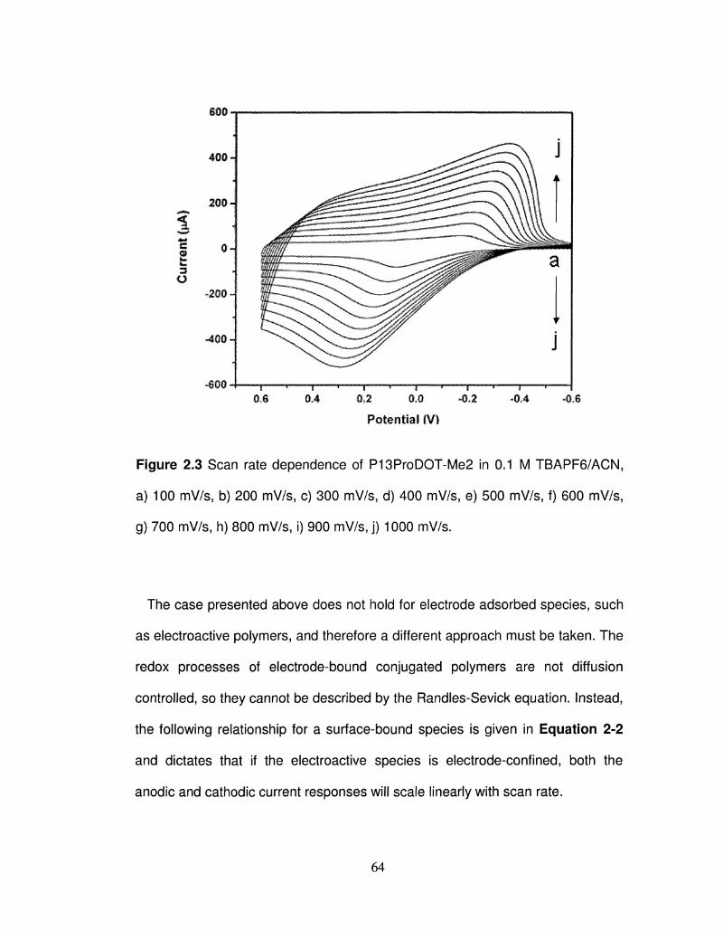
600
•600-1 1 * % * 1 1 1 * 1 s 1 * 1 0,6 0.4 0,2 0,0 -0.2 -0,4 -0.6
Potential (VI
Figure 2.3 Scan rate dependence of P13ProDOT-Me2 in 0.1 M TBAPF6/ACN,
a) 100 mV/s5 b) 200 mV/s, c) 300 mV/s, d) 400 mV/s, e) 500 mV/s, f) 600 mV/s,
g) 700 mV/s, h) 800 mV/s, i) 900 mV/s, j) 1000 mV/s.
The case presented above does not hold for electrode adsorbed species, such
as electroactive polymers, and therefore a different approach must be taken. The
redox processes of electrode-bound conjugated polymers are not diffusion
controlled, so they cannot be described by the Randles-Sevick equation. Instead,
the following relationship for a surface-bound species is given in Equation 2-2
and dictates that if the electroactive species is electrode-confined, both the
anodic and cathodic current responses will scale linearly with scan rate.
64
ip=n2F2rv/4RT 2-2
where F is Faraday's constant (96,485 C/mol) and r is the concentration of
surface bound electroactive centers (mol/cm3). When examination of the
relationship between the peak current responses and increasing scan rate results
in a linear correlation the redox process is said to be non-diffusion controlled, and
the electroactive centers of the polymer are well adhered to the working
electrode surface. In general, the oxidation and reduction of conjugated polymers
is a fast process.However, there are several other factors influence the switching
speeds of a conjugated polymer (e.g film thickness, electrolyte, and the structure
of the polymer itself). Therefore, scan rate dependence studies are essential for
determining whether a polymer can be switched between redox states rapidly
without loss of current response or switching stability.
2.4.3 Square-wave Voltammetry
Square-wave Voltametry involves the switching of potential between two values
instead of a linear potential sweep used for cyclic voltammetry. This technique is
utilized in order to switch the conjugated polymer between the corresponding
redox states, and gives useful informations regarding switching speed, stability of
conjugated polymer as a function of the number of switches, charge transported
during redox processes, and other properties that are useful for practical device
applications. Square-wave Voltametry technique combined with gravimetric
techniques can be used to study the rate of polymerization, doping level and ion-
transport behavior of a conjugated polymer. Furthermore, this can be combined
65
with spectroscopic techniques to get more information about electro-optical
properties of conjugated polymers especially for electrochromic devices.
Generally, chronocoulometry or chronoamperometry are used for this purpose,
and the same electrochemical set up is used as shown in Figure 2.1. Sufficient
time should be given at each potential in order to reach the plateau before
switching to another potential. This technique is also used to perform
electrochemical polymerization at constant potential, generally at peak potential
observed during CV.
2.4.4 Electrochemical Quartz Crystal Microbalance
Electrochemical quartz crystal microbalance (EQCM) is the combination of
quartz crystal microbalance and electroanalytical techniques which gives more
meaning to electrochemical studies (e.g electrochemical polymerization and ion-
transport behavior) by simultaneously measuring the change in mass. Some of
the examples of EQCM studies of CPs are reported in the literature such as
polypyrrole,1 polyaniline,2 and polythiophene.3 The working principle of Quartz
crystal microbalance is based on piezoelectric effect, i.e. variation of resonance
frequency is associated to the applied electric field. EQCM is built with a quartz
crystal coated on both sides with gold and is coupled to the electric source which
then resonates at a given frequency. The deposition of any substance onto
quartz crystal results in the increase in mass, and hence, a dampening of any
oscillation. The relation between change in mass and change in frequency can
be explained by Sauerbrey's equation:
66
Af = -2f02Am/A(pn)1/2 = -Cfm 2-3
where, f0 is the resonant frequency of the fundamental mode of the crystal, p is
the density of the crystal (2.648 g/cm3) and M the shear modulus of quartz (2.947
X 1011 gcm'V2), A is the area of the gold disk coated onto the crystal. Af is the
frequency change caused by addition of mass per unit area of the crystal
surface, Am. It has been observed that 1 Hz change in frequency corresponds to
1.34 ng of material adsorbed/desorbed from the crystal surface of area 0.196
cm2 for a 7.995 MHz crystal. The simplified EQCM experimental set up for
studying electrochemical processes is shown below in Figure 2.4. All the
experiments were carried out using a 1 cm X 1 cm platinum flag as the counter
electrode, and a non-aqueous Ag-Ag+ reference electrode.
Polymers were deposited onto polished gold-coated quartz crystals from 0.01
M monomer solution in 0.1 M electrolyte/ ACN by applying the positive potential
corresponding to the oxidation of the monomer. It should be noted that all
solutions must be filtered before experiments. Polymer deposited onto the gold
coated quartz crystal was washed thoroughly with acetonitrile, and dried before
acquring the electrochemical measurement in a monomer free electrolyte
solution. It should be noted that the electrochemical characterization of polymer
was performed using the same electrolyte solution used for electrochemical
polymerization. In this work, EQCM has been used to determine rate of
polymerization, doping level and ion-transport behavior.
67
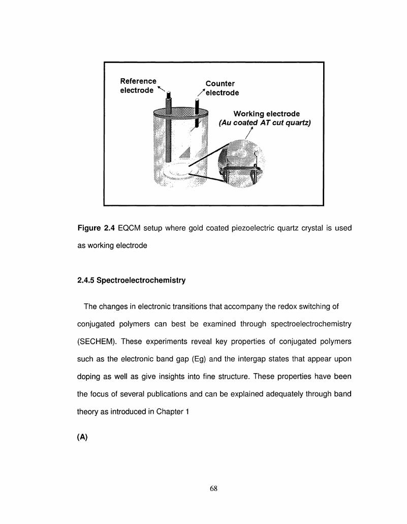
Reference electrode *^
Counter /'electrode
Working electrode (Au coated AT cut quartz)
/
Figure 2.4 EQCM setup where gold coated piezoelectric quartz crystal is used
as working electrode
2.4.5 Spectroelectrochemistry
The changes in electronic transitions that accompany the redox switching of
conjugated polymers can best be examined through spectroelectrochemistry
(SECHEM). These experiments reveal key properties of conjugated polymers
such as the electronic band gap (Eg) and the intergap states that appear upon
doping as well as give insights into fine structure. These properties have been
the focus of several publications and can be explained adequately through band
theory as introduced in Chapter 1
(A)
68
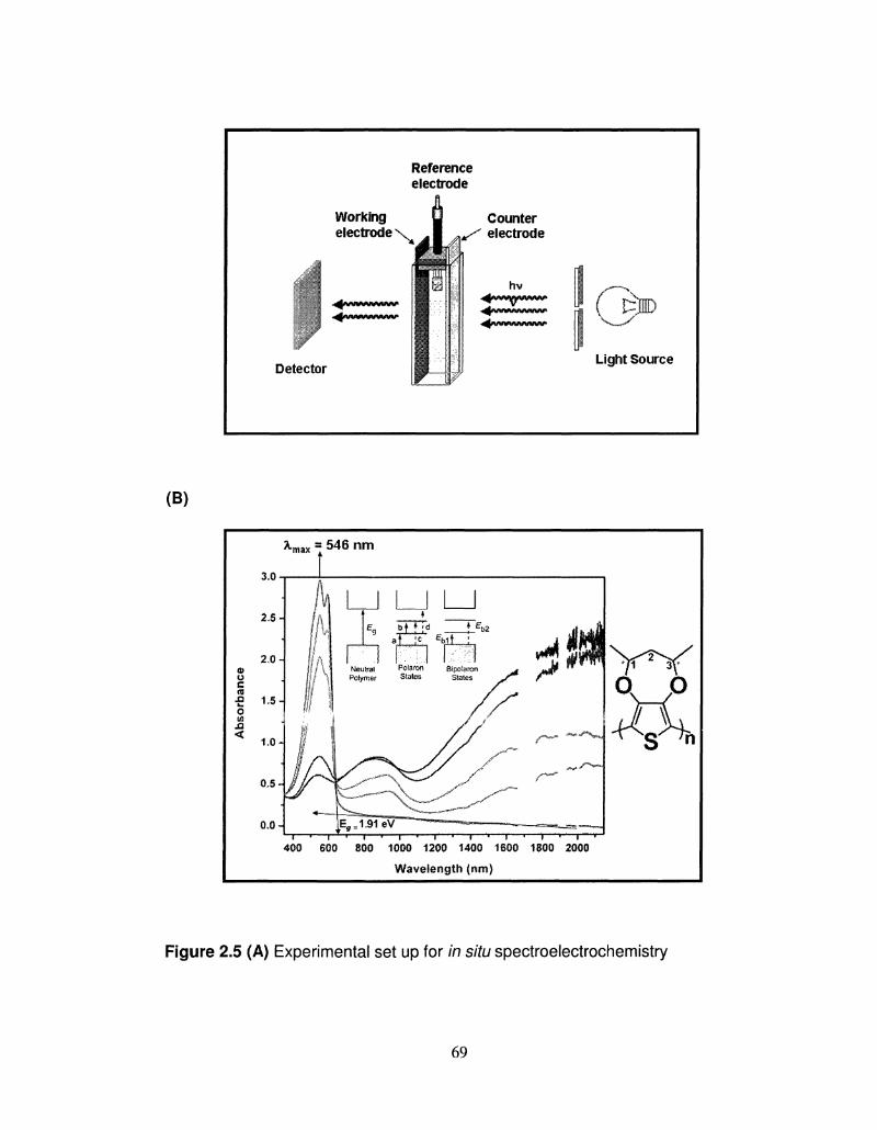
Reference electrode
Working electrode x
Detector
Counter electrode
hv
IF Light Source
* m a x = 5 4 6 n m
i — » — r * " 1 — i — ' — i — « — i — ' — i — * — i — • — i — • — i — '
400 600 800 1000 1200 1400 1600 1800 2000
Wavelength {nm}
Figure 2.5 (A) Experimental set up for in situ spectroelectrochemistry
69
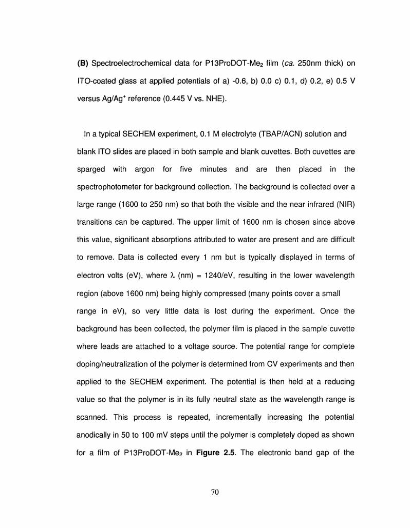
(B) Spectroelectrochemical data for P13ProDOT-Me2 film (ca. 250nm thick) on
ITO-coated glass at applied potentials of a) -0.6, b) 0.0 c) 0.1, d) 0.2, e) 0.5 V
versus Ag/Ag+ reference (0.445 V vs. NHE).
In a typical SECHEM experiment, 0.1 M electrolyte (TBAP/ACN) solution and
blank ITO slides are placed in both sample and blank cuvettes. Both cuvettes are
sparged with argon for five minutes and are then placed in the
spectrophotometer for background collection. The background is collected over a
large range (1600 to 250 nm) so that both the visible and the near infrared (NIR)
transitions can be captured. The upper limit of 1600 nm is chosen since above
this value, significant absorptions attributed to water are present and are difficult
to remove. Data is collected every 1 nm but is typically displayed in terms of
electron volts (eV), where X (nm) = 1240/eV, resulting in the lower wavelength
region (above 1600 nm) being highly compressed (many points cover a small
range in eV), so very little data is lost during the experiment. Once the
background has been collected, the polymer film is placed in the sample cuvette
where leads are attached to a voltage source. The potential range for complete
doping/neutralization of the polymer is determined from CV experiments and then
applied to the SECHEM experiment. The potential is then held at a reducing
value so that the polymer is in its fully neutral state as the wavelength range is
scanned. This process is repeated, incrementally increasing the potential
anodically in 50 to 100 mV steps until the polymer is completely doped as shown
for a film of P13ProDOT-Me2 in Figure 2.5. The electronic band gap of the
70
polymer can be estimated from the onset of the % to n* transition and the
background absorbance as shown in Figure 2.5. In order for this value to be
valid, it is crucial that the polymer be completely neutralized, either
electrochemically or with the aid of a reducing agent additive such as hydrazine.
Upon electrochemical doping, the % to %* peak diminishes, while lower energy
transitions grow in which are attributed to the formation of radical cations that are
free to move along the polymer backbone. At intermediate doping levels, peaks
consistent with a and b (as predicted by Fesser, Bishop and Campbell or FBC
theory) are present (b lies beyond the range of the spectrophotometer, out into
the IR region). Since c and d are not allowed, only two transitions are observed.
Further oxidation can either result in the removal of additional electrons from the
valence band or can remove the unpaired electron from the polaron to form a
dication or bipolaron. Because the bipolaron is an unpaired state, only transitions
from the valence band can occur. Spectrally this is shown as a decrease in the
absorbance transition while a strong absorbance (Eb1) increases in intensity at
even lower energies (into the IR). FBC theory also suggests that the Eb1
transition is much stronger than Eb2 so the bipolaron transition shows as one
peak in the IR region of the spectrum.
2.4.6 Colorimetry
Colorimetry is a quantitative analytical tool that has proven an effective
objectivetechnique to compare and evaluate the optical responses of
electrochromic polymers and devices.4,5 Color can be described in terms of three
attributes; hue, saturation, and luminance, but because of the subjective nature
71
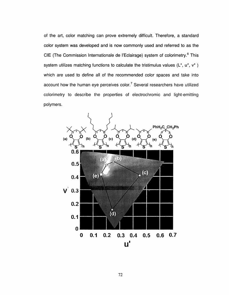
of the art, color matching can prove extremely difficult. Therefore, a standard
color system was developed and is now commonly used and referred to as the
CIE (The Commission Internationale de I'Eclairage) system of colorimetry.6 This
system utilizes matching functions to calculate the tristimulus values (L*, u*, v*)
which are used to define all of the recommended color spaces and take into
account how the human eye perceives color.7 Several researchers have utilized
colorimetry to describe the properties of electrochromic and light-emitting
polymers.
XrttrWtfrtt
0 0.1 0.2 0.3 0.4 0.5 0.6 0.7
U'
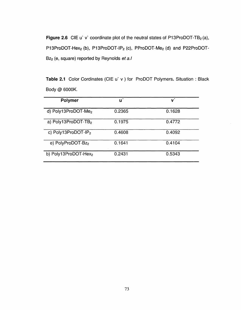
Figure 2.6 CIE if vx coordinate plot of the neutral states of P13ProDOT-TB2(a),
P13ProDOT-Hex2(b), P13ProDOT-IP2 (c), PProDOT-Me2 (d) and P22ProDOT-
Bz2 (e, square) reported by Reynolds eta.l
Table 2.1 Color Cordinates (CIE u' v ) for ProDOT Polymers. Situation : Black
Body @ 6000K.
Polymer
d) Poly13ProDOT-Me2
a) Poly13ProDOT-TB2
c) Poly13ProDOT-IP2
e) PolyProDOT-Bz2
b) Poly13ProDOT-Hex2
u'
0.2365
0.1975
0.4608
0.1641
0.2431
v '
0.1628
0.4772
0.4092
0.4104
0.5343
73
2.5 Reference
1. Baker, C. K.; Reynolds, J. R. J. Electroanal. Chem. 1988, 251, 307-322.
2. Orata, D.; Buttry, D. A. J. Am. Chem. Soc. 1987, 109, 3574-3581.
3. (a) Servagent, S.; Vieil, E. J. Electroanal. Chem. 1990, 280, 227-232. (b)
Hillman, A. R.; Swann, M. J.; Bruckenatein, S. J. Electroanal. Chem. 1990, 291,
147-162. (c) Sawyer, D. T.; Sobkowiak, A.; Roberts J., J. L. Electrochemistry
for Chemists, 2nd ed.; John Wiley & Sons: New York, 1995, Chapter 3
4. Kueni, R. G. Color: an Introduction to Practice and Principles; Wiley: New
York, 1996.
5. Berns, R. S. Billmeyer and Saltzman's Principles of Color Technology; 3rd
ed., JohnWiley & Sons: New York, 2000.
6. CIE. Colorimetry (Official Recommendations of the International Commission
on Illumination); CIE Publication No. 15, CIE: Paris 1971.
7. Wyszecki, G.; Stiles, W. S. Color for Science, Art, and Technology, Nassau,
K., Ed.; Elsevier: Amsterdam, 1998; p 31.
74
CHAPTER 3
ELECTROCHROMIC CONJUGATED POLYMERS FROM 1,3-
DISUBSTITUTED PROPYLENEDIOXYTHIOPHENE (13ProDOT-R2)
3.1 Introduction
Conjugated polymers offer a unique combination of properties which makes
them a suitable alternative to current materials used in many apllications such as
electrochromics,1 "4 organic gas sensors,5"7 non-linear optics,8 light-emitting
diodes (LEDs)9 energy storage batteries,10 charge dissipaters,11 corrosion
protectors, 12 and solar cells 13~14. For display applications, color and color tuning
are of prime importance. Monomer derivatization, often by incorporating electron
donating or electron withdrawing groups, is frequently employed to achieve color
tuning directly or to impart solubility which can result in an inadvertent color shift.
Herein, we describe a facile derivatization of a popular heterocycle, 3,4-
propylenedioxythiophene (ProDOT), resulting in a 200 nm shift in the Amax of the
absorbance spectrum for the neutral polymer compared to conventional
poly(ProDOT). Common derivatives of this molecule are typically made at the 2,2
position (the central carbon on the propylenedioxy bridge), however we have
accomplished 1,3-disubstitution with a t-butyl group, hexyl group, isopropyl
group, methyl group and benzyl group resulting in 1,3-di-t-butylProDOT
(13ProDOT-TB2), 1,3-dihexylProDOT (13ProDOT-Hex2) 1,3-diisopropylProDOT
(13ProDOT-IP2), 1,3-dimethylProDOT (13ProDOT-Me2) and 1,3-dibenzylProDOT
(13ProDOT-Bz2). The polymer from 2,2-dimethylProDOT, commonly abbreviated
75
PProDOT-Me2, was used for comparison with these new derivatives. Chemical
structures of the polymers used herein are shown in Figure 3.1.
Conjugated polymers based on 3,4-ethylenedioxythiophene (EDOT) and its
derivatives have gained much attention because of their low oxidation potentials,
high contrast and high conductivity.15'20 The electron-donating effect of the
oxygens at the 3 and 4 positions, coupled with favorable ring geometry, stabilize
the positive charge along the polymer backbone, rendering high stability of
poly(EDOT) (PEDOT) in its p-doped state. The electrochemical polymerization of
EDOT takes place at a low oxidation potential, and the polymer exhibits a band
gap (Eg) of 1.6eV.21"23 Polymers based on alkylenedioxythiophenes are popular
materials in electrochromics for their ability to change color from deep blue to
almost colorless. PEDOT has the ability to transit from deep blue to sky blue
upon oxidation with a Photopic contrast of 54%.24'25 Photopic contrast is a value
which takes into account the entire visible spectrum, weighted to the sensitivity of
the human eye. Higher Photopic contrasts and more colorless bleached states
can be obtained by the incorporation of an additional methylene unit into the
bridge between the oxygens, as with 3,4-propylenedioxythiophene (ProDOT). 26
Derivatization of ProDOT at the central carbon (so-called 2,2-disubstitution)
introduces a higher degree of disorder between polymer chains, reducing the
residual color of poly(ProDOT) (PProDOT) in the oxidized state while maintaining
an intense blue-purple in neutral states. 27 One polymer that exhibits enhanced
Photopic contrast (up to 75%) is PProDOT-Me2) whose monomer was
synthesized by the etherification of 3,4-dimethoxythiophene (DMOT) and
76
neopentyl glycol. The highest contrast (89%) reported to date was in the case
of the benzyl derivative, PProDOT-Bz2.29
Generally, there are three strategies for changing color transitions in
conjugated electrochromic systems. The first relies upon extent of
polymerization. The Eg of a conjugated polymer can be tuned by controlling the
number of repeat units. Eg decreases with increasing conjugation length, limited
by Peierls distortion. 30~31 Second, changing the electronic environment via
incorporation of electron donating substituents (red shift) or electron withdrawing
groups (blue shift). Third, introduce steric interactions between the polymer
backbone, causing an increase in the dihedral angle between aromatic rings,
thereby decreasing TT orbital overlap. This results in a blue shifted max and an
increased Eg observed both for unsubstituted ProDOT as well as 2,2-
disubstituted ProDOT. It is this approach that yielded the 200 nm blue shift for
P13ProDOT-TB2. The bulky t-butyl group disrupted the Tr-conjugated system in
the polymer; these interactions caused a severe shift in its coloration properties.
The ability to tune color transitions via simple derivatization would be an
attractive approach towards achieving a larger swath of the color gamut. Density
Functional Theory (DFT) calculations for these materials were carried out in
order to model these effects (see Supporting Information). The large difference in
band gap, 0.73 eV (experimentally measured), between PProDOT-Me2 and
P13ProDOT-TB2 can be explained by distortion of backbone planarity. The
dihedral angles of dimers were studied to give qualitative information about
dihedral angles in the polymer. The optimized calculated structure of the
77
13ProDOT-TB2 dimer shows a dihedral angle of 76.1°, resulting in a clear
distortion of planarity along the polymer backbone (Figure 1). Both ProDOT-Me2
and the hypothetical 22ProDOT-TB2 dimers show a 180° dihedral angle, offering
no such distortion. The 1,3-disubstitution approach, therefore, causes greater
changes in color properties than 2,2-disubstitution with the same moiety.
To date, studies of ProDOT have been carried out using 2,2-disubstition but
none have reported 1,3-disubstitution. These derivatives will provide a disruption
of conjugation in the polymer backbone, ultimately increasing the energy of the n-
71* transition. The steric interactions decrease interchain interactions of the
polymer thereby increasing the optical transparency in the bleached state. 32-34
Theoretically, 1,3 substituents would project over the conjugated polymer
backbone, thereby interacting to distort thiophenes out of planarity as compared
to unsubstituted ProDOT polymers. The distortion will be proportional to the size
of the substituents. Attaching larger groups may cause an even greater shift into
the UV, and current work is being undertaken to push the limits of these steric
effects. Potentially, a conjugated electrochromic material could become
transparent in the neutral state and colored in the oxidized state. Further, it may
also be possible to shift the peak transitions entirely out of the visible region for
both states, resulting in a polymer which is UV-absorbing in the neutral state and
NIR-absorbing in its oxidized state. One can envision an interesting series of
applications for such a material, particularly for coatings on windows.
Longer alkyl substituents would provide solubility in organic solvents. 35-37
Traditional solution processing may then be used (spray or spin coating).
78
Literature indicates a vast amount of conducting polymer based electrochromic
materials reflecting blue and red colors in their neutral state. To date, there are
few reports of the synthesis of a truly yellow polymer in the neutral state that
becomes green in the oxidized state. The class of green polymers 38-39 reported
are based on donor-acceptor theory; none have been from a single molecule,
such as 13ProDOT-TB2. In this chapter, we have accomplished a facile
transetherification procedure for 1,3-disubstitution using t-butyl groups, isopropyl
groups, methyl groups, hexyl groups and benzyl groups resulting in 1,3-di-t-
butylProDOT(13ProDOT-TB2), 1,3-di-iso-propylProDOT (13ProDOT-IP2) , 1,3-di-
methylProDOT (13ProDOT-Me2), 1,3-di-hexylProDOT(13ProDOT-Hex2) and 1,3-
dibenzylProDOT (13ProDOT-Bz2) respectively. The polymer obtained from 1, 3
disubstituted ProDOT (P13ProDOT) resulted upto 200 nm shift in the Amax as
compared to conventionally derivatized 2, 2 disubstituted PProDOT. The polymer
of this new derivative, P13ProDOT-TB2 and P13ProDOT-Hex2 are organic-
soluble and can be processed by a variety of solution methods, including spray
coating. The remarkable shift in the band gap resulted in a yellow (Y) to green
color transition from the neutral to oxidized states, respectively, whereas
P13ProDOT-IP2 is insoluble and showing intermediate band gap with a red color
in the neutral and transmissive light blue in the oxidised state. P13ProDOT-Me2
and P13ProDOT-Bz2 both undergo from a deep blue-purple color to light blue
during their redox cycles. Neutral P13ProDOT-Hex2 is orange in color but upon
oxidation it gives light green color. The chemical structures of these polymers
are shown in Figure 3.1
79
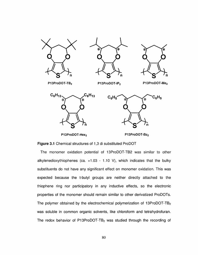
QO * *
QO
+CH -fOf.
CRH 6n13 CRH 6n13
S •» P13ProDOT-IP2
C6H5
S '" P13ProDOT-Me2
C6H5
*s' /n N s P13ProDOT-Hex2 P13ProDOT-Bz2
Figure 3.1 Chemical structures of 1,3 di substituted ProDOT
The monomer oxidation potential of 13ProDOT-TB2 was similar to other
alkylenedioxythiophenes (ca. +1.03 - 1.10 V), which indicates that the bulky
substituents do not have any significant effect on monomer oxidation. This was
expected because the t-butyl groups are neither directly attached to the
thiophene ring nor participatory in any inductive effects, so the electronic
properties of the monomer should remain similar to other derivatized ProDOTs.
The polymer obtained by the electrochemical polymerization of 13ProDOT-TB2
was soluble in common organic solvents, like chloroform and tetrahydrofuran.
The redox behavior of P13ProDOT-TB2 was studied through the recording of
80
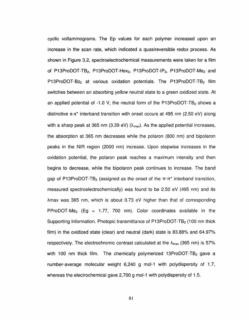
cyclic voltammograms. The Ep values for each polymer increased upon an
increase in the scan rate, which indicated a quasireversible redox process. As
shown in Figure 3.2, spectroelectrochemical measurements were taken for a film
of P13ProDOT-TB2, P13ProDOT-Hex2, P13ProDOT-IP2, P13ProDOT-Me2 and
P13ProDOT-Bz2 at various oxidation potentials. The P13ProDOT-TB2 film
switches between an absorbing yellow neutral state to a green oxidized state. At
an applied potential of -1.0 V, the neutral form of the P13ProDOT-TB2 shows a
distinctive n-n* interband transition with onset occurs at 495 nm (2.50 eV) along
with a sharp peak at 365 nm (3.39 eV) (A,max). As the applied potential increases,
the absorption at 365 nm decreases while the polaron (800 nm) and bipolaron
peaks in the NIR region (2000 nm) increase. Upon stepwise increases in the
oxidation potential, the polaron peak reaches a maximum intensity and then
begins to decrease, while the bipolaron peak continues to increase. The band
gap of P13ProDOT-TB2 (assigned as the onset of the TT-TT* interband transition,
measured spectroelectrochemically) was found to be 2.50 eV (495 nm) and its
Amax was 365 nm, which is about 0.73 eV higher than that of corresponding
PProDOT-Me2 (Eg = 1.77, 700 nm). Color coordinates available in the
Supporting Information. Photopic transmittance of P13ProDOT-TB2 (100 nm thick
film) in the oxidized state (clear) and neutral (dark) state is 83.88% and 64.97%
respectively. The electrochromic contrast calculated at the Amax (365 nm) is 57%
with 100 nm thick film. The chemically polymerized 13ProDOT-TB2 gave a
number-average molecular weight 6,240 g mol-1 with polydispersity of 1.7,
whereas the electrochemical gave 2,700 g mol-1 with polydispersity of 1.5.
81
Wavelength (nm)
Figure 3.2 Overlays of P13ProDOT-R2
3.2 Experimental
Materials. Acetonitrile (ACN) and chloroform (CHCI3) were purchased from
Thermo-Fisher and distilled over calcium hydride before use. Ethyl acetate, n-
hexane and toluene were purchased from Thermo-Fisher; toluene was distilled
over sodium before use. Pinacolone, pivaladdehyde, tetra-n-butylammonium
hexafluorophosphate (TBAPF6), tetra-n-butylammonium perchlorate (TBAP), and
lithium diisopropylamide (LDA) were purchased from Aldrich and used as
received. 3,4-Dimethoxythiophene (DMOT) was purchased from TCI America
82
and used as received. Dodecylbenzene sulfonic acid (DBSA) was purchased
from Acros Organics and used as received. Indium-doped Tin Oxide (ITO)-
coated glass slides (Rs = 8-12 CI) were purchased from Delta Technologies and
cleaned by sonication in acetone prior to use. The reaction scheme for
synthesizing 13ProDOT-TB2 involves trans-etherification reactions between
DMOT and a (3S,5R)-2,2,6,6-tetramethylheptane-3,5-diol under acid catalyzed
(DBSA) conditions. Synthetic details of all the monomers and polymers have
been dicussed in the later part of this chapter.
Electrochemistry. Electrochemical polymerizations, cyclic voltammetry, scan
rate studies, and spectroelectrochemistry were carried out with CHI 400 and
660A potentiostats. Solution studies were carried out using 0.1 M TBAPF6 / ACN
solutions, with respect to a non-aqueous Ag/Ag+ reference electrode, calibrated
to 0.445 V vs. NHE. Detailed electrochemistry is discussed later.
Optical Characterization. Film thicknesses were obtained using a Veeco
DekTak mechanical profilometer. Spectroelectrochemistry was carried out with a
Varian Cary 5000 UV-Vis-NIR spectrophotometer with a 150 mm DRA
Integrating Sphere and Color software. Color data were calculated using a 10
degree standard observer angle, a measurement range of 360 nm to 860 nm in 1
nm intervals, and a standard D65 illuminant.
83
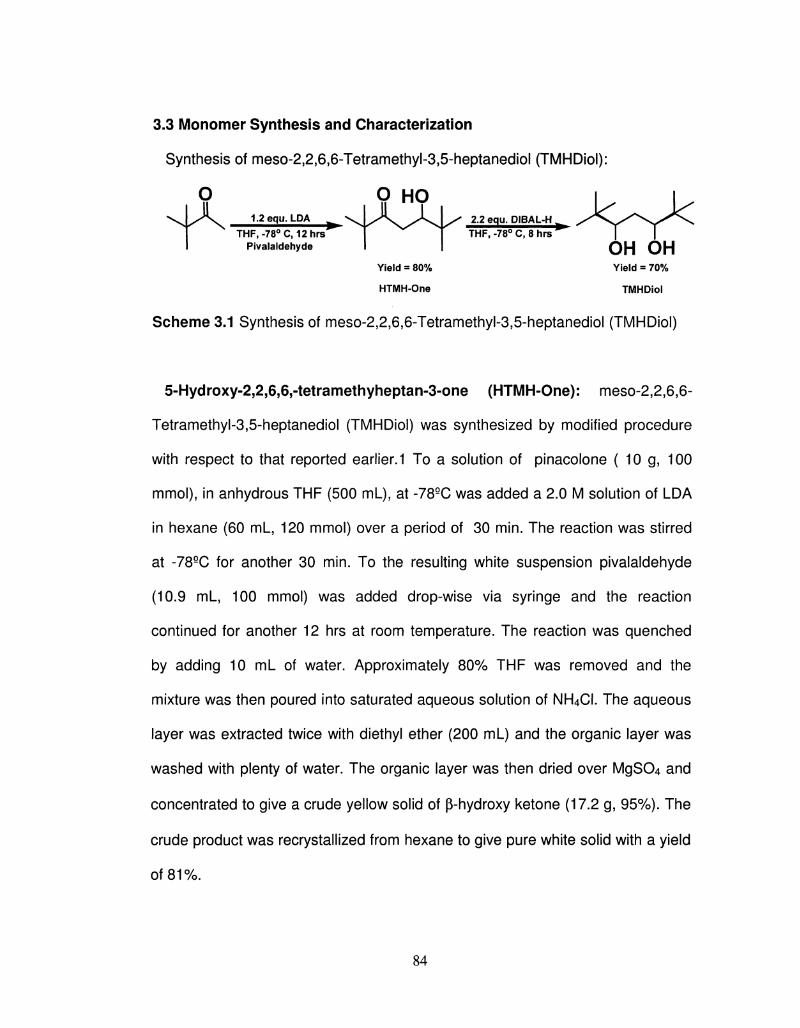
3.3 Monomer Synthesis and Characterization
Synthesis of meso-2,2,6,6-Tetramethyl-3,5-heptanediol (TMHDiol):
Q Q HO ^ x 1.2equ.LDA V L / V y A . | y ^ 2.2 equ. DIBAL-H
THF,-78°C,12hrs | | THF, -78° C, 8 hrs Pivalaldehyde I I O H O H
Yield = 80% Yield = 70%
HTMH-One TMHDiol
Scheme 3.1 Synthesis of meso-2,2,6,6-Tetramethyl-3,5-heptanediol (TMHDiol)
5-Hydroxy-2,2,6,6,-tetramethyheptan-3-one (HTMH-One): meso-2,2,6,6-
Tetramethyl-3,5-heptanediol (TMHDiol) was synthesized by modified procedure
with respect to that reported earlier. 1 To a solution of pinacolone ( 10 g, 100
mmol), in anhydrous THF (500 mL), at -78QC was added a 2.0 M solution of LDA
in hexane (60 mL, 120 mmol) over a period of 30 min. The reaction was stirred
at -78QC for another 30 min. To the resulting white suspension pivalaldehyde
(10.9 mL, 100 mmol) was added drop-wise via syringe and the reaction
continued for another 12 hrs at room temperature. The reaction was quenched
by adding 10 mL of water. Approximately 80% THF was removed and the
mixture was then poured into saturated aqueous solution of NH4CI. The aqueous
layer was extracted twice with diethyl ether (200 mL) and the organic layer was
washed with plenty of water. The organic layer was then dried over MgS04 and
concentrated to give a crude yellow solid of p-hydroxy ketone (17.2 g, 95%). The
crude product was recrystallized from hexane to give pure white solid with a yield
of 81%.
84
1H NMR (CDCI3, 400 MHz, 5): 3.64 (IH,ddd), 3.16 (IH, d), 2.74 (IH, dd), 2.46 (IH,
dd), 1.14 (9H, s) 0.91 (9H, s); 13C-NMR: 209.23, 75.26, 38.11, 34.45, 26.50,
25.93; FTIR (KBr): 3475, 2800, 1700, 1460, 1380, 1360, 1320, 1280, 1060, 1000
cm-l.
Meso-2,2,6,6-Tetramethyl-3,5-heptanediol (TMHDiol): To a solution of p-
hydroxy ketone (10 g, 53 mmol) in THF (250 ml_) was added 1 M Dibal in
hexane, (118 ml_, 118 mmol) at -789C, and the solution was stirred for 2 hrs at
this temperature. The reaction mixture was allowed to warm to room temperature
and continued for another 8 hrs at room temperature. After 8 hrs the reaction
mixture was quenched with 2 N aqueous HCL solution. The mixture was then
extracted twice with ether (200 mL), and the combined organic layer was washed
with saturated aqueous NaHC03 solution and with brine. Drying with anhydrous
MgS04 and concentration gave the TMHDiol (9 g, 90% yield) as a white solid.
1H NMR (CDCI3, 400 MHz, 5): 3.54 (2H, bs), 3.45 (2H5 dd), 1.74 (1H, ddd), 1.31
(1H, ddd), 0.91 (18H, s); 13C-NMR: 81.82, 35.23, 31.29, 25.99, 25.80; FTIR
(KBr): 3400 (b), 2910, 1480, 1130, 880 cm-1. Anal. Calcd for C„H2402: C, 70.16;
H, 12.85. Found: C, 70.08; H, 12.57. ; HRMS (ESI): m/z [M + Na]+ calcd for
CnH2402Na: 211.1259; found: 211.1263.
85
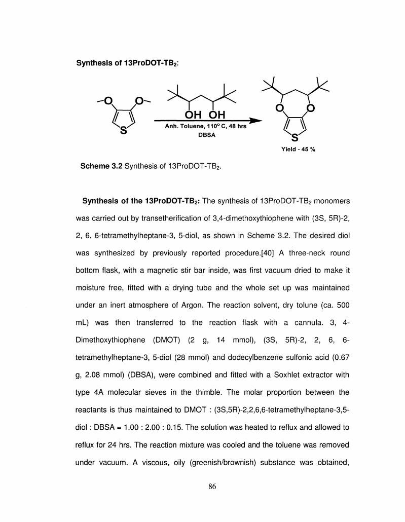
Synthesis of 13ProDOT-TB2:
-o o-YX OH OH ^ °W° \ Q / Anh. Toluene, 110°C, 48 hrs
DBSA Q Yield - 45 %
Scheme 3.2 Synthesis of 13ProDOT-TB2.
Synthesis of the 13ProDOT-TB2: The synthesis of 13ProDOT-TB2 monomers
was carried out by transetherification of 3,4-dimethoxythiophene with (3S, 5R)-2,
2, 6, 6-tetramethylheptane-3, 5-diol, as shown in Scheme 3.2. The desired diol
was synthesized by previously reported procedure.[40] A three-neck round
bottom flask, with a magnetic stir bar inside, was first vacuum dried to make it
moisture free, fitted with a drying tube and the whole set up was maintained
under an inert atmosphere of Argon. The reaction solvent, dry tolune (ca. 500
mL) was then transferred to the reaction flask with a cannula. 3, 4-
Dimethoxythiophene (DMOT) (2 g, 14 mmol), (3S, 5R)-2, 2, 6, 6-
tetramethylheptane-3, 5-diol (28 mmol) and dodecylbenzene sulfonic acid (0.67
g, 2.08 mmol) (DBSA), were combined and fitted with a Soxhlet extractor with
type 4A molecular sieves in the thimble. The molar proportion between the
reactants is thus maintained to DMOT : (3S,5R)-2,2,6,6-tetramethylheptane-3,5-
diol : DBSA = 1.00 : 2.00 : 0.15. The solution was heated to reflux and allowed to
reflux for 24 hrs. The reaction mixture was cooled and the toluene was removed
under vacuum. A viscous, oily (greenish/brownish) substance was obtained,
86
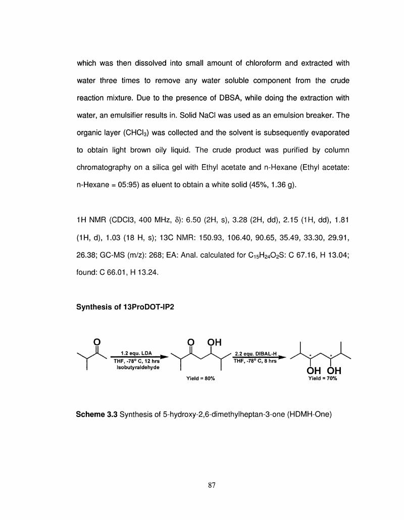
which was then dissolved into small amount of chloroform and extracted with
water three times to remove any water soluble component from the crude
reaction mixture. Due to the presence of DBSA, while doing the extraction with
water, an emulsifier results in. Solid NaCI was used as an emulsion breaker. The
organic layer (CHCI3) was collected and the solvent is subsequently evaporated
to obtain light brown oily liquid. The crude product was purified by column
chromatography on a silica gel with Ethyl acetate and n-Hexane (Ethyl acetate:
n-Hexane = 05:95) as eluent to obtain a white solid (45%, 1.36 g).
1H NMR (CDCI3, 400 MHz, 5): 6.50 (2H, s), 3.28 (2H, dd), 2.15 (1H, dd), 1.81
(1H, d), 1.03 (18 H, s); 13C NMR: 150.93, 106.40, 90.65, 35.49, 33.30, 29.91,
26.38; GC-MS (m/z): 268; EA: Anal, calculated for C15H24O2S: C 67.16, H 13.04;
found: C 66.01, H 13.24.
Synthesis of 13ProDOT-IP2
O \ ^ V . 1.2 equ. LDA ,
| ^ THF,-78°C, 12hrs I Isobutyraldehyde
Yield = 80% Yield = 70%
Scheme 3.3 Synthesis of 5-hydroxy-2,6-dimethylheptan-3-one (HDMH-One)
yj yjn 2.2 equ. DIBAL-H
THF, -78° C, 8 hrs
r\LJ A U
87
5-hydroxy-2,6-dimethylheptan-3-one (HDMH-One): To a solution of 3-
methylbutan-2-one ( 10 g, 116 mmol), in anhydrous THF (500 mL), at -78QC was
added a 2.0 M solution of LDA in hexane (70 mL, 140 mmol) over a period of 30
min. The reaction was stirred at -78QC for another 30 min. To the resulting white
suspension Isobutyraldehyde (8.4 mL, 116 mmol) was added drop-wise via
syringe and the reaction continued for another 12 hrs at room temperature. The
reaction was quenched by adding 10 mL of water. Approximately 80% THF was
removed and the mixture was then poured into saturated aqueous solution of
NH4CI. The aqueous layer was extracted twice with diethyl ether (200 mL) and
the organic layer was washed with plenty of water. The organic layer was then
dried over MgS04 and concentrated to give a crude white oil of p-hydroxy ketone
(16.5 g, 90%). The crude product was recrystallized from petroleum ether to give
pure white solid with a yield of 76%.
1H NMR (CDCI3, 400 MHz, 5): 3.61 (IH,ddd), 3.12 (IH, d), 2.68 (IH, dd)5 2.40 (IH,
dd), 1.12 (6H, s) 0.89 (6H, s); 13C-NMR: 209.45, 75.11, 38.03, 34.41, 26.35;
FTIR (KBr): 3475, 2800, 1700, 1460, 1380, 1360, 1320, 1280, 1060, 1000 cm-l.
(3R,5S)-2,6-dimethylheptane-3,5-diol (DMH-Diol): To a solution of (3-hydroxy
ketone (10 g, 63 mmol) in THF (250 mL) was added 1 M Dibal in hexane, (126
mL, 126 mmol) at -78QC, and the solution was stirred for 2 hrs at this
temperature. The reaction mixture was allowed to warm to room temperature and
continued for another 8 hrs at room temperature. After 8 hrs the reaction mixture
was quenched with 2 N aqueous HC1 solution. The mixture was then extracted
88
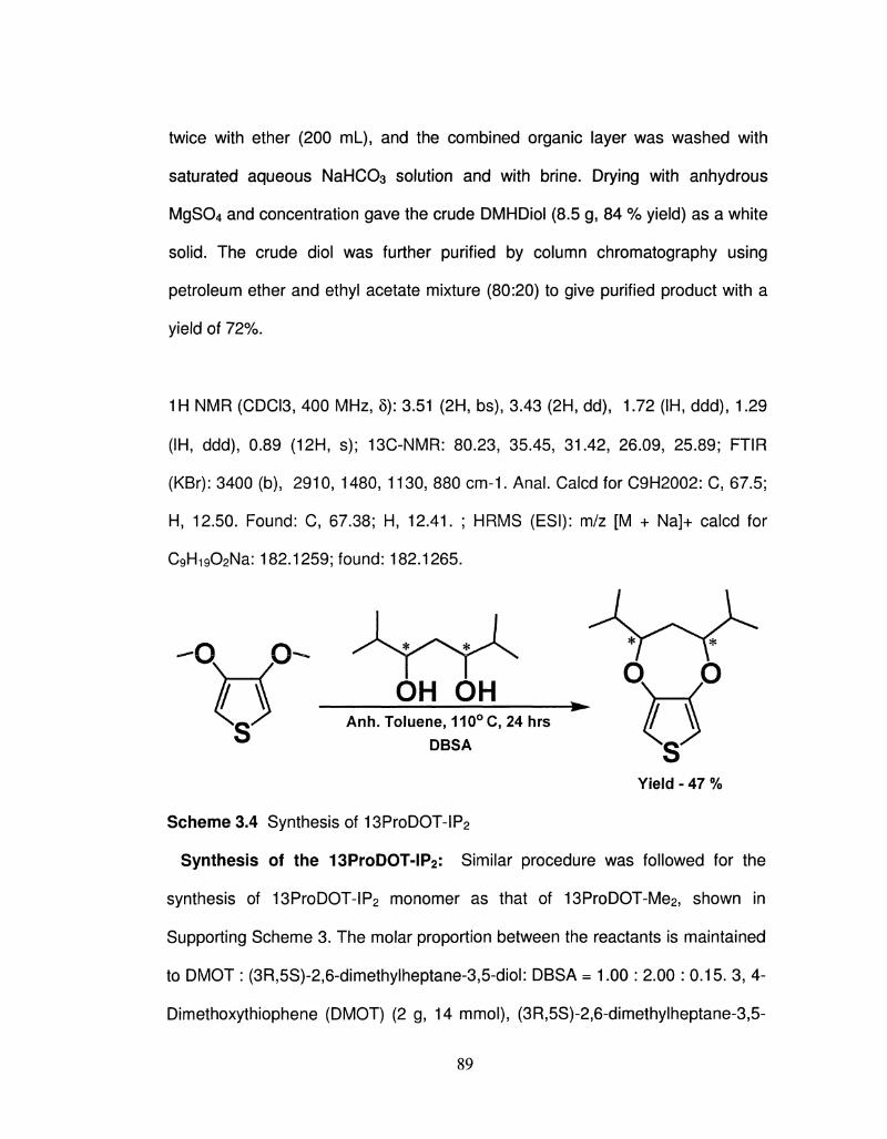
twice with ether (200 ml_), and the combined organic layer was washed with
saturated aqueous NaHCC>3 solution and with brine. Drying with anhydrous
MgS04 and concentration gave the crude DMHDiol (8.5 g, 84 % yield) as a white
solid. The crude diol was further purified by column chromatography using
petroleum ether and ethyl acetate mixture (80:20) to give purified product with a
yield of 72%.
1H NMR (CDCI3, 400 MHz, 5): 3.51 (2H, bs), 3.43 (2H, dd), 1.72 (IH, ddd), 1.29
(IH, ddd), 0.89 (12H, s); 13C-NMR: 80.23, 35.45, 31.42, 26.09, 25.89; FTIR
(KBr): 3400 (b), 2910, 1480, 1130, 880 cm-1. Anal. Calcd for C9H2002: C, 67.5;
H, 12.50. Found: C, 67.38; H, 12.41. ; HRMS (ESI): m/z [M + Na]+ calcd for
C9Hi902Na: 182.1259; found: 182.1265.
o o OH OH ^ \—/
Anh. Toluene, 110° C, 24 hrs DBSA
Yield - 47 %
Scheme 3.4 Synthesis of 13ProDOT-IP2
Synthesis of the 13ProDOT-IP2: Similar procedure was followed for the
synthesis of 13ProDOT-IP2 monomer as that of 13ProDOT-Me2, shown in
Supporting Scheme 3. The molar proportion between the reactants is maintained
to DMOT : (3R,5S)-2,6-dimethylheptane-3,5-diol: DBSA = 1.00 : 2.00 : 0.15. 3, 4-
Dimethoxythiophene (DMOT) (2 g, 14 mmol), (3R,5S)-2,6-dimethylheptane-3,5-
89
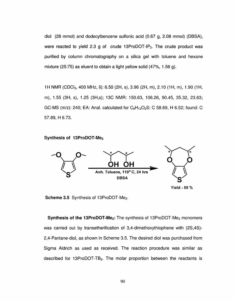
diol (28 mmol) and dodecylbenzene sulfonic acid (0.67 g, 2.08 mmol) (DBSA),
were reacted to yield 2.3 g of crude 13ProDOT-IP2. The crude product was
purified by column chromatography on a silica gel with toluene and hexane
mixture (25:75) as eluent to obtain a light yellow solid (47%, 1.56 g).
1H NMR (CDCI3, 400 MHz, 5): 6.50 (2H, s), 3.96 (2H, m), 2.10 (1H, m), 1.90 (1H,
m), 1.55 (3H, s), 1.25 (3H,s); 13C NMR: 150.63, 106.26, 90.45, 35.32, 23.63;
GC-MS (m/z): 240; EA: Anal, calculated for C9H12O2S: C 58.69, H 6.52; found: C
57.89, H 6.73.
Synthesis of 13ProDOT-Me2
OH OH Anh. Toluene, 110°C, 24 hrs
DBSA // w
S" Yield - 55 %
Scheme 3.5 Synthesis of 13ProDOT-Me2.
Synthesis of the 13ProDOT-Me2: The synthesis of 13ProDOT-Me2 monomers
was carried out by transetherification of 3,4-dimethoxythiophene with (2S,4S)-
2,4-Pantane-diol, as shown in Scheme 3.5. The desired diol was purchased from
Sigma Aldrich as used as received. The reaction procedure was similar as
described for 13ProDOT-TB2. The molar proportion between the reactants is
90
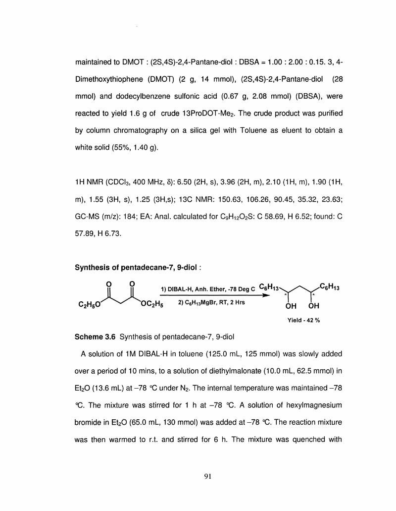
maintained to DMOT : (2S,4S)-2,4-Pantane-diol : DBSA = 1.00 : 2.00 : 0.15. 3, 4-
Dimethoxythiophene (DMOT) (2 g, 14 mmol), (2S,4S)-2,4-Pantane-diol (28
mmol) and dodecylbenzene sulfonic acid (0.67 g, 2.08 mmol) (DBSA), were
reacted to yield 1.6 g of crude 13ProDOT-Me2. The crude product was purified
by column chromatography on a silica gel with Toluene as eluent to obtain a
white solid (55%, 1.40 g).
1H NMR (CDCI3, 400 MHz, 5): 6.50 (2H, s), 3.96 (2H, m), 2.10 (1H, m), 1.90 (1H,
m), 1.55 (3H, s), 1.25 (3H,s); 13C NMR: 150.63, 106.26, 90.45, 35.32, 23.63;
GC-MS (m/z): 184; EA: Anal, calculated for C9H1202S: C 58.69, H 6.52; found: C
57.89, H 6.73.
Synthesis of pentadecane-7, 9-diol:
II || 1)DIBAL-H,Anh. Ether,-78 DegC C 6 H i 3 \ ^ ^ \ ^ C 6 H 1 3
CzHsO^^^^OCzHs 2) C6H13MgBr, RT, 2 Hrs ^ ^
Yield - 42 %
Scheme 3.6 Synthesis of pentadecane-7, 9-diol
A solution of 1M DIBAL-H in toluene (125.0 mL, 125 mmol) was slowly added
over a period of 10 mins, to a solution of diethylmalonate (10.0 mL, 62.5 mmol) in
Et20 (13.6 mL) at -78 °C under N2. The internal temperature was maintained -78
°C. The mixture was stirred for 1 h at -78 °C. A solution of hexylmagnesium
bromide in Et20 (65.0 mL, 130 mmol) was added at-78 °C. The reaction mixture
was then warmed to r.t. and stirred for 6 h. The mixture was quenched with
91
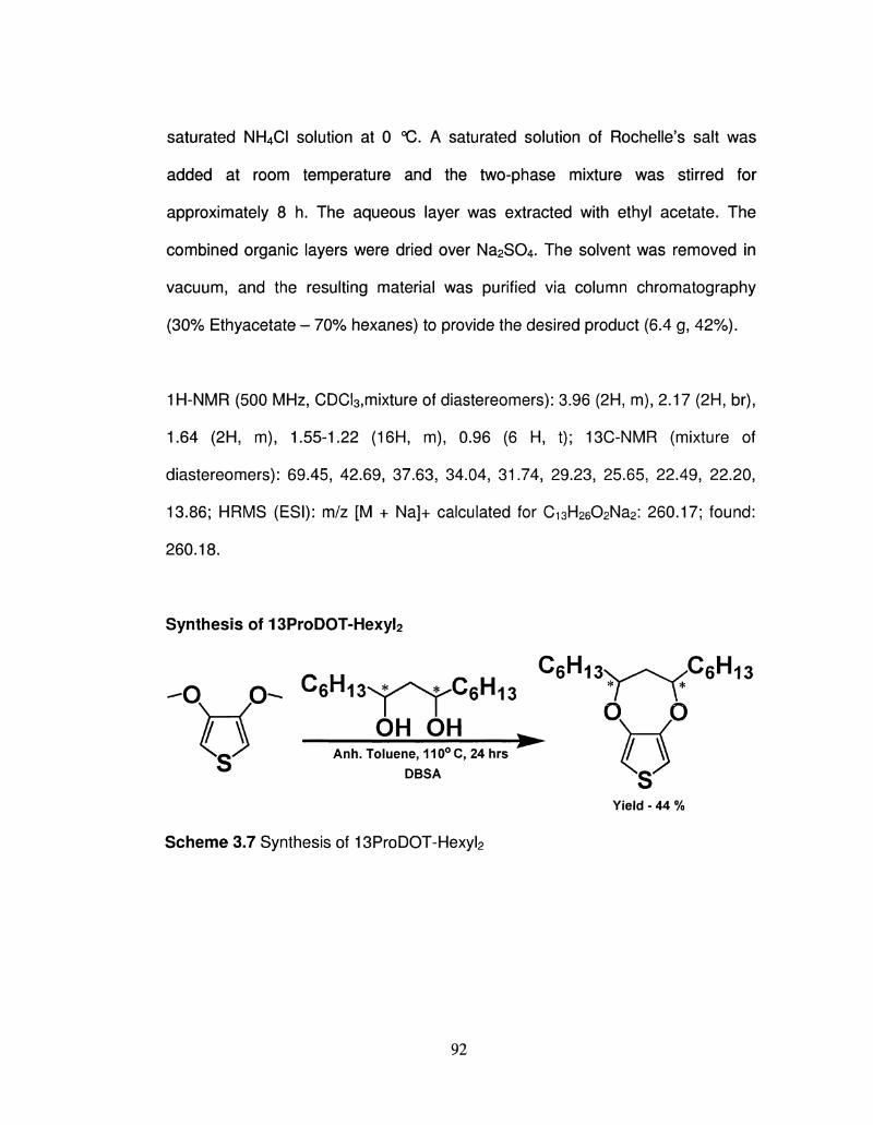
saturated NH4CI solution at 0 °C. A saturated solution of Rochelle's salt was
added at room temperature and the two-phase mixture was stirred for
approximately 8 h. The aqueous layer was extracted with ethyl acetate. The
combined organic layers were dried over Na2S04. The solvent was removed in
vacuum, and the resulting material was purified via column chromatography
(30% Ethyacetate - 70% hexanes) to provide the desired product (6.4 g, 42%).
1H-NMR (500 MHz, CDCI3,mixture of diastereomers): 3.96 (2H, m), 2.17 (2H, br),
1.64 (2H, m), 1.55-1.22 (16H, m), 0.96 (6 H, t); 13C-NMR (mixture of
diastereomers): 69.45, 42.69, 37.63, 34.04, 31.74, 29.23, 25.65, 22.49, 22.20,
13.86; HRMS (ESI): m/z [M + Na]+ calculated for Ci3H2602Na2: 260.17; found:
260.18.
Synthesis of 13ProDOT-Hexyl2
-O O - ^ 6 H I 3 N A X ^ S J ^ C 6 H 1 3 * r T * ^6Hi3\^^-v./CeH-13
\ { I I O O ^ OH OH . O ^ Anh. Toluene, 110°C, 24 hrs // \
DBSA ^ Q '
Yield - 44 %
Scheme 3.7 Synthesis of 13ProDOT-Hexyl2
92
Synthesis of 13ProDOT-Hexyl2: The 3-neck RBF, with a magnetic stir bar
inside, was first vacuum dried to make it moisture free, fitted with thermometer
and the drying tube and the whole set up was maintained under an inert
atmosphere of N2. The reaction solvent, dry tolune (~ 500 mL) was then
transferred to the RBF with a cannula. 3, 4-Dimethoxythiophene (DMOT) (2 g, 14
mmol), 1, 5-dihexyl-pentane-2, 4-diol (28 mmol) and dodecylbenzene sulfonic
acid (0.67 g, 2.08 mmol) (DBSA), were combined and fitted with a Soxhlet
extractor with type 4 A molecular sieves in the thimble. The molar proportion
between the reactants is thus maintained to DMOT: 1, 5-dihexyl-pentane-2, 4-
diol: DBSA = 1.00: 2.00: 0.15. The reaction is shown in scheme 3.7. The solution
was heated to reflux and allowed to reflux for 24 h. The reaction mixture was
cooled and the toluene was removed under vacuum. A viscous oily dark greenish
substance was obtained, which was then dissolved into small amount of
chloroform and extracted with water three times to remove any water soluble
component from the crude reaction mixture. Due to the presence of DBSA, while
doing the extraction with water, an emulsifier results in. Solid NaCI was used as
an emulsion breaker. The organic layer (CHCI3) was collected and the solvent is
subsequently evaporated to obtain a green/brown oily liquid. The crude product
was purified by column chromatography on a silica gel using Ethyl acetate and n-
Hexane (Ethyl acetate: n-Hexane = 05:95) solvent mixtures with 1.98 gm of
purified product.
1H-NMR (500 MHz, CDCI3): 6.37 (2H, s), 4.28 (2H, m), 2.02 (2H, t), 1.75 (4H, q),
1.53 (4H, m), 1.33 (12H, m) 0.94 (6H, t); 13C-NMR: 149.03, 103.55, 78.46,
93
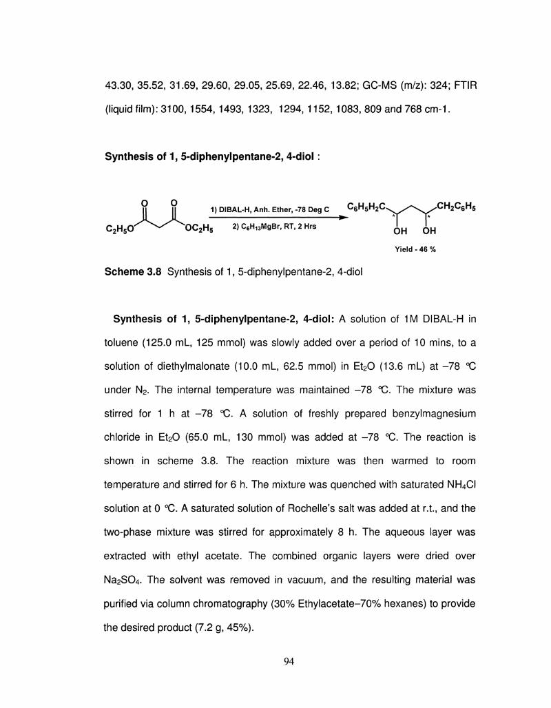
43.30, 35.52, 31.69, 29.60, 29.05, 25.69, 22.46, 13.82; GC-MS (m/z): 324; FTIR
(liquid film): 3100, 1554, 1493, 1323, 1294, 1152, 1083, 809 and 768 cm-1.
Synthesis of 1, 5-diphenylpentane-2, 4-diol:
O O 1) DIBAL-H, Anh. Ether, -78 Deg C C e H s h ^ C x ^ ^ ^ v ^ ^ C I ^ C e H s II M 1) DIBAL-H, Anh. Ether, -78 Deg C u 6 M 5 n 2 ^ \ ^ / s \ ^
C2H5O^^T>C2H5 2)C6H13MgBr,RT,2Hrs J ^ ^
Yield - 46 %
Scheme 3.8 Synthesis of 1, 5-diphenylpentane-2, 4-diol
Synthesis of 1, 5-diphenylpentane-2, 4-diol: A solution of 1M DIBAL-H in
toluene (125.0 mL, 125 mmol) was slowly added over a period of 10 mins, to a
solution of diethylmalonate (10.0 mL, 62.5 mmol) in Et20 (13.6 mL) at -78 °C
under N2. The internal temperature was maintained -78 °C. The mixture was
stirred for 1 h at -78 °C. A solution of freshly prepared benzylmagnesium
chloride in Et20 (65.0 mL, 130 mmol) was added at -78 °C. The reaction is
shown in scheme 3.8. The reaction mixture was then warmed to room
temperature and stirred for 6 h. The mixture was quenched with saturated NH4CI
solution at 0 °C. A saturated solution of Rochelle's salt was added at r.t., and the
two-phase mixture was stirred for approximately 8 h. The aqueous layer was
extracted with ethyl acetate. The combined organic layers were dried over
Na2S04. The solvent was removed in vacuum, and the resulting material was
purified via column chromatography (30% Ethylacetate-70% hexanes) to provide
the desired product (7.2 g, 45%).
94
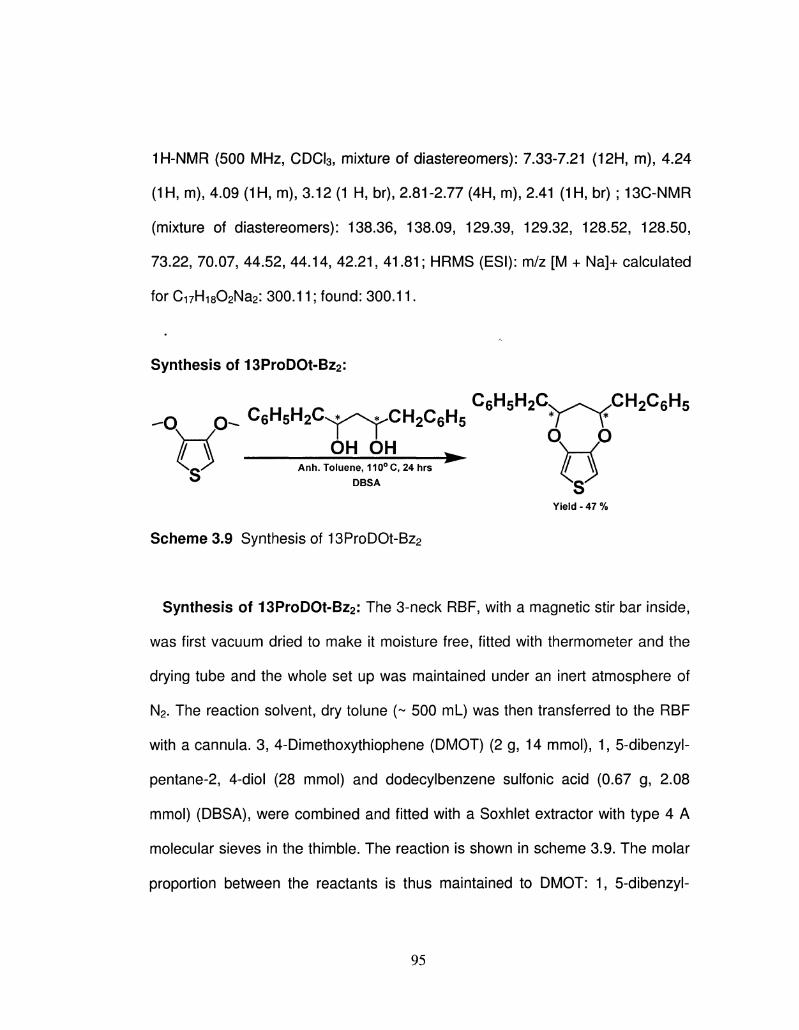
1H-NMR (500 MHz, CDCI3, mixture of diastereomers): 7.33-7.21 (12H, m), 4.24
(1H, m), 4.09 (1H, m), 3.12 (1 H, br), 2.81-2.77 (4H, m), 2.41 (1H, br) ; 13C-NMR
(mixture of diastereomers): 138.36, 138.09, 129.39, 129.32, 128.52, 128.50,
73.22, 70.07, 44.52, 44.14, 42.21, 41.81; HRMS (ESI): m/z [M + Na]+ calculated
for Ci7Hi802Na2: 300.11; found: 300.11.
Synthesis of 13ProDOt-Bz2:
-O CK C6H5H2CS^^CH2C6H5 Y^C \—/ L. L. Q o o OH OH w W
O ^ Anh. Toluene, 110°C, 24 hrs ^ DBSA ^Q'
Yield - 47 %
Scheme 3.9 Synthesis of 13ProDOt-Bz2
Synthesis of 13ProDOt-Bz2: The 3-neck RBF, with a magnetic stir bar inside,
was first vacuum dried to make it moisture free, fitted with thermometer and the
drying tube and the whole set up was maintained under an inert atmosphere of
N2. The reaction solvent, dry tolune (~ 500 mL) was then transferred to the RBF
with a cannula. 3, 4-Dimethoxythiophene (DMOT) (2 g, 14 mmol), 1, 5-dibenzyl-
pentane-2, 4-diol (28 mmol) and dodecylbenzene sulfonic acid (0.67 g, 2.08
mmol) (DBSA), were combined and fitted with a Soxhlet extractor with type 4 A
molecular sieves in the thimble. The reaction is shown in scheme 3.9. The molar
proportion between the reactants is thus maintained to DMOT: 1, 5-dibenzyl-
95
pentane-2, 4-diol: DBSA = 1.00: 2.00: 0.15. The solution was heated to reflux
and allowed to reflux for 24 h. The reaction mixture was cooled and the toluene
was removed under vacuum. A viscous oily (greenish/brownish) substance was
obtained, which was then dissolved into small amount of chloroform and
extracted with water three times to remove any water soluble component from
the crude reaction mixture. Due to the presence of DBSA, while doing the
extraction with water, an emulsifier results in. Solid NaCI was used as an
emulsion breaker. The organic layer (CHCI3) was collected and the solvent is
subsequently evaporated to obtain a green/brown oily liquid. The crude product
was purified by column chromatography using Ethyl acetate and n-Hexane (Ethyl
acetate: n-Hexane = 10:90) solvent mixtures.
1H-NMR (500 MHz, CDCI3): 6.28 (2H, s), 4.52 (2H, m), 3.04 (2H, m), 2.78 (2H,
m), 2.06 (2 H, m); 13C-NMR: 148.43, 137.84, 129.33, 129.21, 128.30, 128.26,
126.41, 104.20, 78.79, 41.82, 41.60; GC-MS (m/z): 336; FTIR (liquid film): 3100,
1554, 1493, 1323, 1294, 1152, 1083, 809 and 768 cm1-
3.3Poly13ProDOT-R2
3.3.1 Electrochemical synthesis and characterization :
All electrochemical experiments were performed using a three-cell
configuration in 0.1 M TBAPF6/ACN with a CHI 400a potentiostat. The reference
electrode was a nonaqueous Ag/Ag+ electrode consisting of a silver wire
immersed in a glass capillary body fitted with a Vycor tip and filled with 0.1 M
96
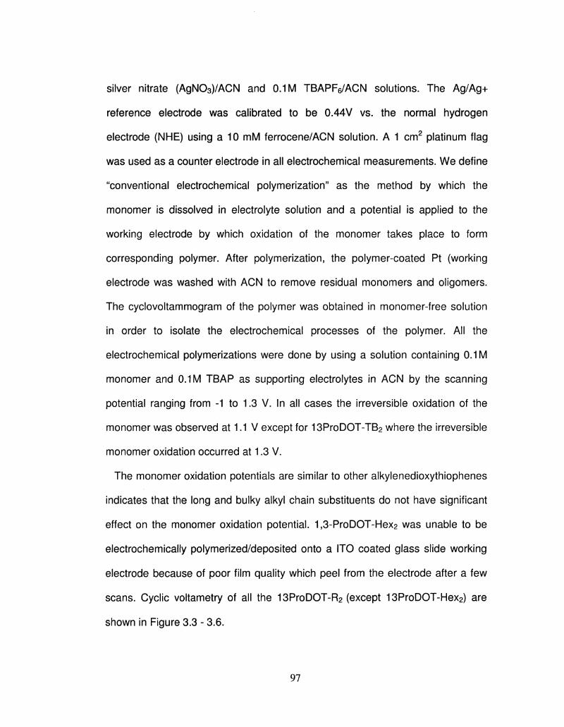
silver nitrate (AgN03)/ACN and 0.1 M TBAPFe/ACN solutions. The Ag/Ag+
reference electrode was calibrated to be 0.44V vs. the normal hydrogen
electrode (NHE) using a 10 mM ferrocene/ACN solution. A 1 cm2 platinum flag
was used as a counter electrode in all electrochemical measurements. We define
"conventional electrochemical polymerization" as the method by which the
monomer is dissolved in electrolyte solution and a potential is applied to the
working electrode by which oxidation of the monomer takes place to form
corresponding polymer. After polymerization, the polymer-coated Pt (working
electrode was washed with ACN to remove residual monomers and oligomers.
The cyclovoltammogram of the polymer was obtained in monomer-free solution
in order to isolate the electrochemical processes of the polymer. All the
electrochemical polymerizations were done by using a solution containing 0.1 M
monomer and 0.1 M TBAP as supporting electrolytes in ACN by the scanning
potential ranging from -1 to 1.3 V. In all cases the irreversible oxidation of the
monomer was observed at 1.1 V except for 13ProDOT-TB2 where the irreversible
monomer oxidation occurred at 1.3 V.
The monomer oxidation potentials are similar to other alkylenedioxythiophenes
indicates that the long and bulky alkyl chain substituents do not have significant
effect on the monomer oxidation potential. 1,3-ProDOT-Hex2 was unable to be
electrochemically polymerized/deposited onto a ITO coated glass slide working
electrode because of poor film quality which peel from the electrode after a few
scans. Cyclic voltametry of all the 13ProDOT-R2 (except 13ProDOT-Hex2) are
shown in Figure 3.3 - 3.6.
97
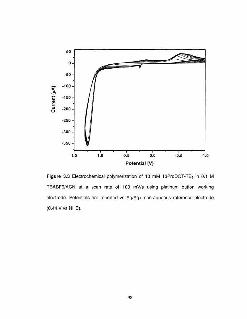
50
0
-50
-100
-150-
-200
-250
-300 -j
-350 J
1.5 1.0 0.5 0.0
Potential (V)
-0.5 -1.0
Figure 3.3 Electrochemical polymerization of 10 mM 13ProDOT-TB2 in 0.1 M
TBABF6/ACN at a scan rate of 100 mV/s using platinum button working
electrode. Potentials are reported vs Ag/Ag+ non-aqueous reference electrode
(0.44 V vs NHE).
98
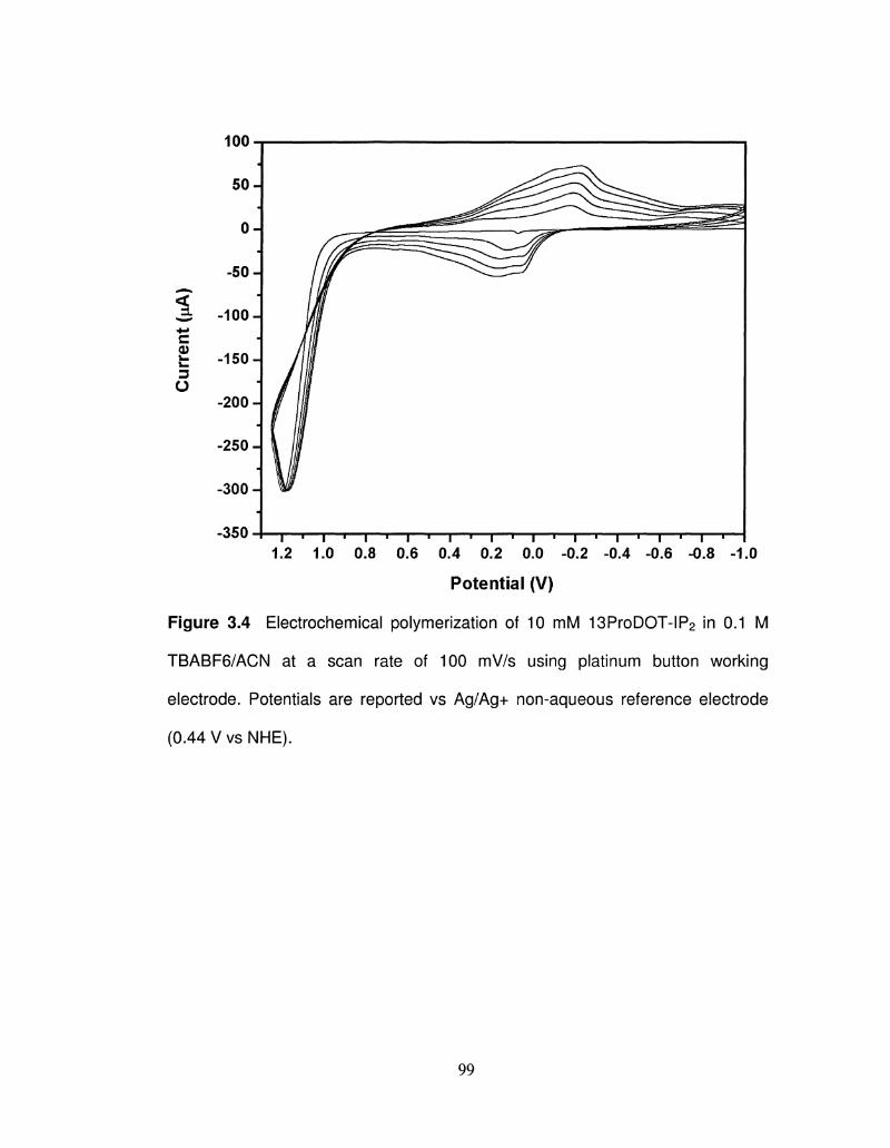
-350 1.2 1.0 0.8 0.6 0.4 0.2 0.0 -0.2 -0.4 -0.6 -0.8 -1.0
Potential (V)
Figure 3.4 Electrochemical polymerization of 10 mM 13ProDOT-IP2 in 0.1 M
TBABF6/ACN at a scan rate of 100 mV/s using platinum button working
electrode. Potentials are reported vs Ag/Ag+ non-aqueous reference electrode
(0.44 V vs NHE).
99
i c
o
-1000 1.2 1.0 0.8 0.6 0.4 0.2 0.0 -0.2 -0.4 -0.6
Potential (V)
Figure 3.5 Electrochemical polymerization of 10 mM 13ProDOT-Me2 in 0.1 M
TBABF6/ACN at a scan rate of 100 mV/s using platinum button working
electrode. Potentials are reported vs Ag/Ag+ non-aqueous reference electrode
(0.44 V vs NHE).
100
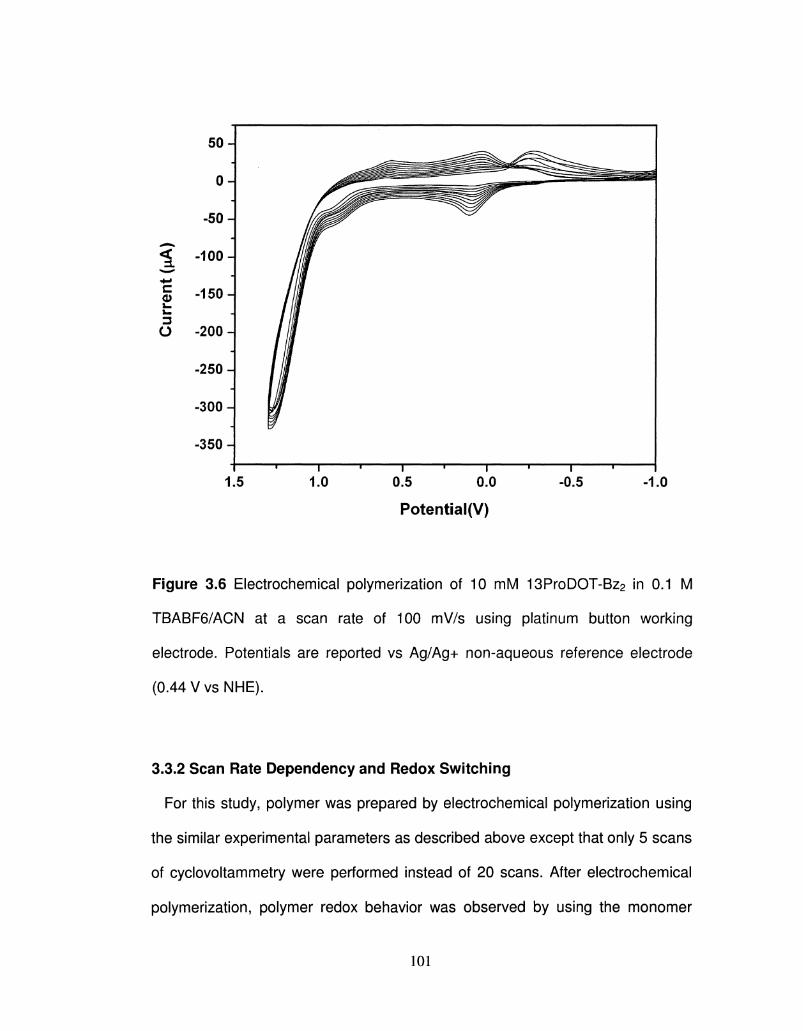
50
0
-50
^ -100
1 -150
O -200
-250
-300-
-350-
1.5 1.0 0.5 0.0 -0.5 -1.0
Potential(V)
Figure 3.6 Electrochemical polymerization of 10 mM 13ProDOT-Bz2 in 0.1 M
TBABF6/ACN at a scan rate of 100 mV/s using platinum button working
electrode. Potentials are reported vs Ag/Ag+ non-aqueous reference electrode
(0.44 V vs NHE).
3.3.2 Scan Rate Dependency and Redox Switching
For this study, polymer was prepared by electrochemical polymerization using
the similar experimental parameters as described above except that only 5 scans
of cyclovoltammetry were performed instead of 20 scans. After electrochemical
polymerization, polymer redox behavior was observed by using the monomer
101
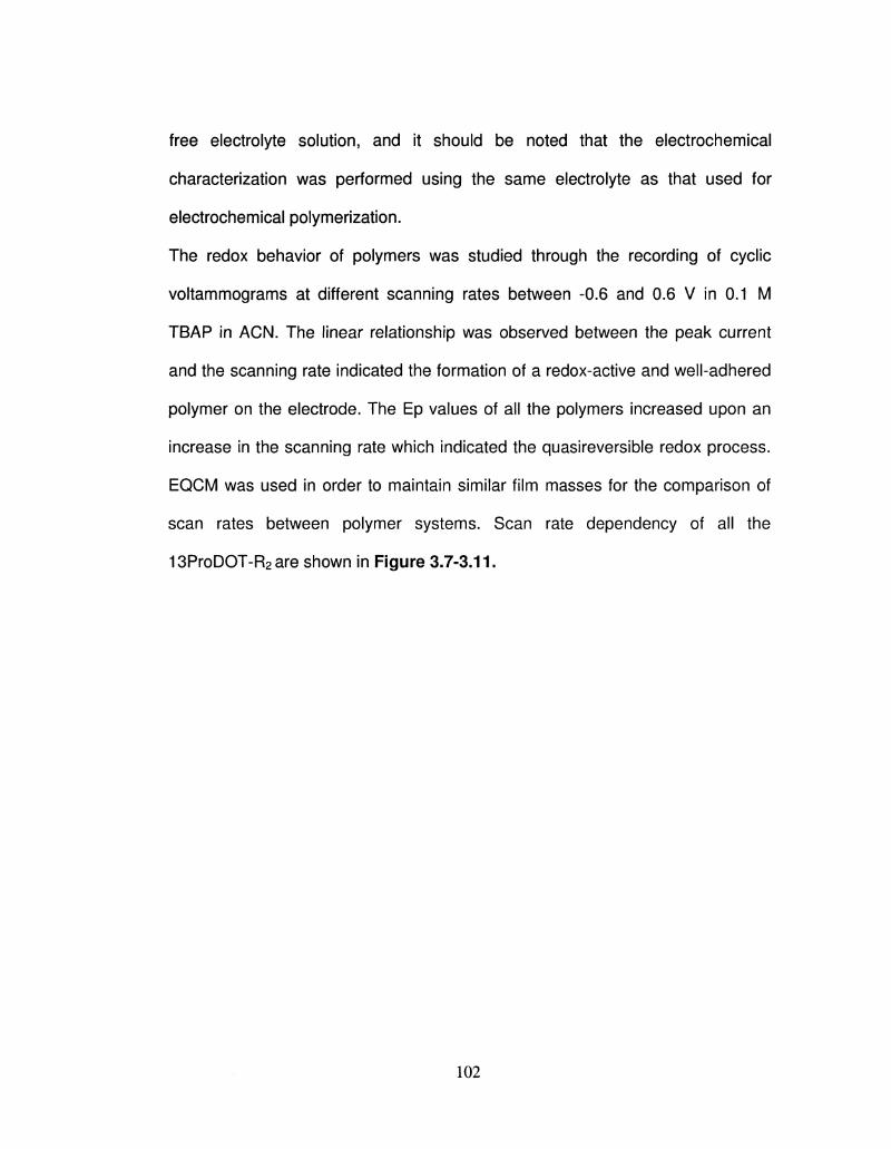
free electrolyte solution, and it should be noted that the electrochemical
characterization was performed using the same electrolyte as that used for
electrochemical polymerization.
The redox behavior of polymers was studied through the recording of cyclic
voltammograms at different scanning rates between -0.6 and 0.6 V in 0.1 M
TBAP in ACN. The linear relationship was observed between the peak current
and the scanning rate indicated the formation of a redox-active and well-adhered
polymer on the electrode. The Ep values of all the polymers increased upon an
increase in the scanning rate which indicated the quasireversible redox process.
EQCM was used in order to maintain similar film masses for the comparison of
scan rates between polymer systems. Scan rate dependency of all the
13ProDOT-R2are shown in Figure 3.7-3.11.
102
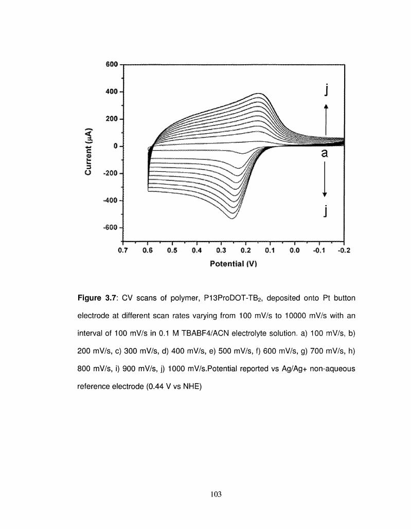
5 w :Z3-
o -200
-400-J
*S0O H
0*G -0+1 -Q.2
Potential (V)
Figure 3.7: CV scans of polymer, P13ProDOT-TB2, deposited onto Pt button
electrode at different scan rates varying from 100 mV/s to 10000 mV/s with an
interval of 100 mV/s in 0.1 M TBABF4/ACN electrolyte solution, a) 100 mV/s3 b)
200 mV/s, c) 300 mV/s, d) 400 mV/s, e) 500 mV/s, f) 600 mV/s, g) 700 mV/s, h)
800 mV/s, i) 900 mV/s, j) 1000 mV/s.Potential reported vs Ag/Ag+ non-aqueous
reference electrode (0.44 V vs NHE)
103
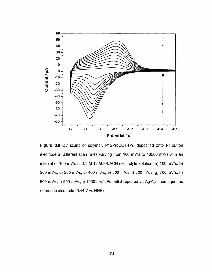
Cur
rent
/ \iA
60- |
5 0 -
4 0 -
3 0 -
2 0 -
1 0 H
oJ -10 J
-20 J
-30 J -40 J
-50 J -60 J
-70 J -80 J
-I I I I I I I I I I I I I I I I
0.2 0.1 0.0 -0.1 -0.2 -0.3 -0.4 -0.5
Potential / V
Figure 3.8 CV scans of polymer, P13ProDOT-IP2> deposited onto Pt button
electrode at different scan rates varying from 100 mV/s to 10000 mV/s with an
interval of 100 mV/s in 0.1 M TBABF4/ACN electrolyte solution, a) 100 mV/s, b)
200 mV/s, c) 300 mV/s, d) 400 mV/s, e) 500 mV/s, f) 600 mV/s, g) 700 mV/s, h)
800 mV/s, i) 900 mV/s, j) 1000 mV/s.Potential reported vs Ag/Ag+ non-aqueous
reference electrode (0.44 V vs NHE)
104
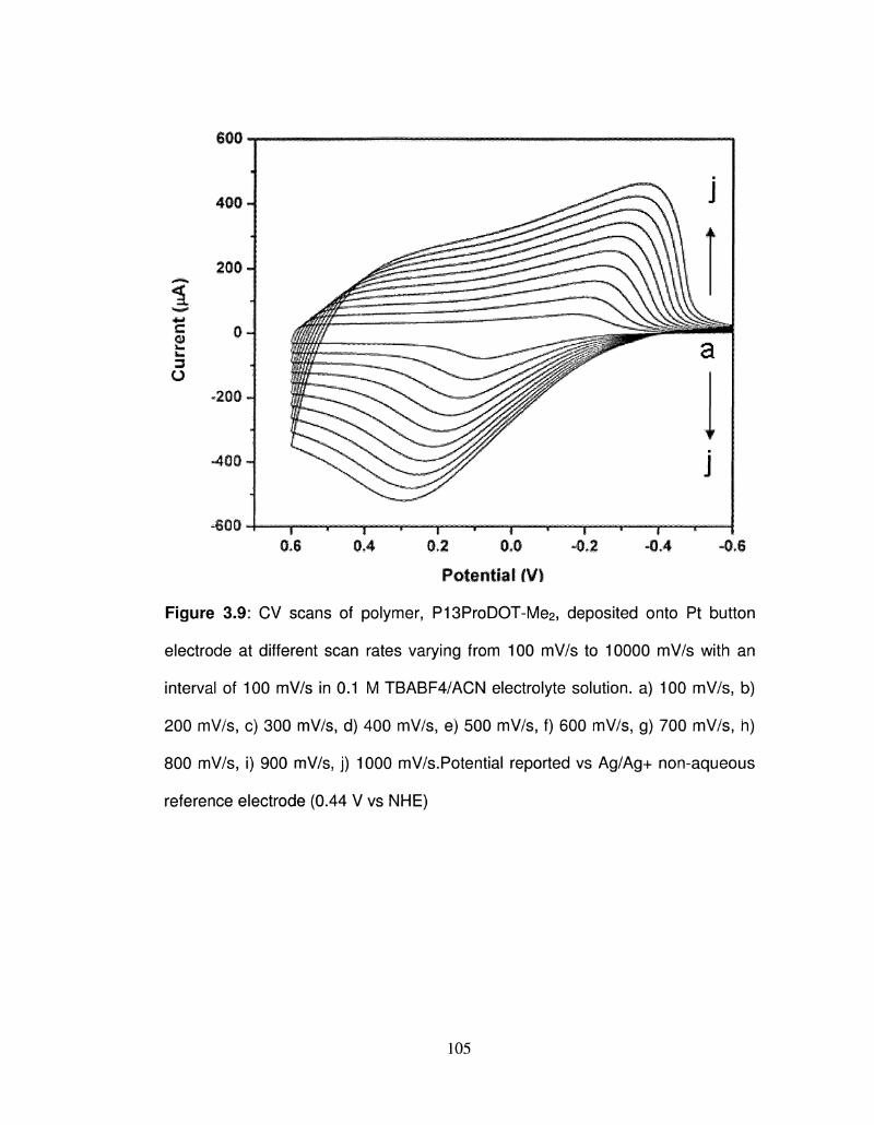
€00
§J 0.4 0,2 0.0 -0,2 -0,4 -0,6
Potential m
Figure 3.9: CV scans of polymer, P13ProDOT-Me2) deposited onto Pt button
electrode at different scan rates varying from 100 mV/s to 10000 mV/s with an
interval of 100 mV/s in 0.1 M TBABF4/ACN electrolyte solution, a) 100 mV/s, b)
200 mV/s, c) 300 mV/s, d) 400 mV/s, e) 500 mV/s, f) 600 mV/s, g) 700 mV/s, h)
800 mV/s, i) 900 mV/s, j) 1000 mV/s.Potential reported vs Ag/Ag+ non-aqueous
reference electrode (0.44 V vs NHE)
105
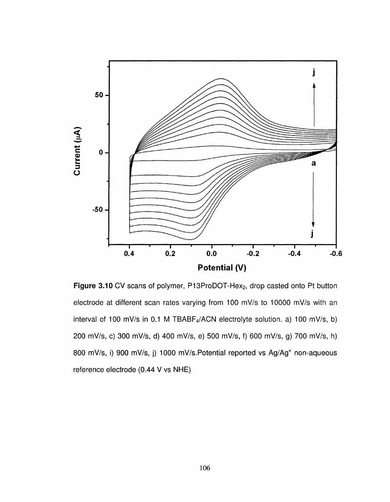
Potential (V)
Figure 3.10 CV scans of polymer, P13ProDOT-Hex2, drop casted onto Pt button
electrode at different scan rates varying from 100 mV/s to 10000 mV/s with an
interval of 100 mV/s in 0.1 M TBABF4/ACN electrolyte solution, a) 100 mV/s, b)
200 mV/s, c) 300 mV/s, d) 400 mV/s, e) 500 mV/s, f) 600 mV/s, g) 700 mV/s, h)
800 mV/s, i) 900 mV/s, j) 1000 mV/s.Potential reported vs Ag/Ag+ non-aqueous
reference electrode (0.44 V vs NHE)
106
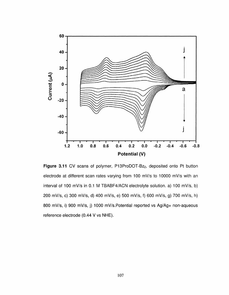
60
T—'—r— r*""~T—*"—i—'i •—i « i ' i •-- > » i ' i 1.2 1.0 0.8 0.6 0.4 0.2 0.0 -0.2 -0.4 -0.6 -0.8
Potential |V)
Figure 3.11 CV scans of polymer, P13ProDOT-Bz2, deposited onto Pt button
electrode at different scan rates varying from 100 mV/s to 10000 mV/s with an
interval of 100 mV/s in 0.1 M TBABF4/ACN electrolyte solution, a) 100 mV/s, b)
200 mV/s, c) 300 mV/s, d) 400 mV/s, e) 500 mV/s, f) 600 mV/s, g) 700 mV/s, h)
800 mV/s, i) 900 mV/s, j) 1000 mV/s.Potential reported vs Ag/Ag+ non-aqueous
reference electrode (0.44 V vs NHE).
107
3.3.3 Optical Properties
3.3.3.1 In-situ Spectroelectrochemistry
Spectroelectrochemistry: The spectroelectrochemistry of all the polymers was
performed with ITO-coated glass as a working electrode.The polymers were
formed via cyclovoltammetric growth from 0.01 M monomer solution in 0.1 M
TBAP/acetonitrile by scanning the potential between -1.0 and 1.3 V for 20 cycles
at a scan rate of 100mV/s. The polymer films were then repeatedly washed with
ACN to remove the monomers and oligomers and then placed into a glass
cuvette with monomer free electrolyte. The UV-Vis spectra of the polymers were
recorded by using Ag/Ag+ nonaqueous reference electrode described in the
electrochemistry section, and the counter electrode was another ITO-coated
glass which allows for the passage of light. All optoelectrochemical experiments
were carried out under a nitrogen atmosphere.
At -1.0 V P13ProDOT-TB2 film was yellow in color and a peak was observed at
max value of 365 nm. Upon the stepwise increase of oxidation potential of
P13ProDOT-TB2 the absorbance of the K-K* transition decreased, and the peak
due to the polaron increased at a higher wavelength IR region. At 1.0 V the
polymer became green in color.
For P13ProDOT-Bz2, two peaks were observed at 573 and 623 nm at -1.0 V
which is due to the vibronic coupling. 15,19.At 1.0 V, the absorbance of n-n*
decreased, and the polymer became transparent.
108
The photopic contrast was calculated from the difference in percentage
transmittance (%T) between the completely reduced and oxidized states and the
contrast was 65% for P13ProDOT-Bz2.
The spectroelectrochemistry of all other polymers was performed by following
the similar procedure and P13ProDOT-Me2 also showed two peaks at Xvnax
values of 550 and 576 nm. P13ProDOT-Me2 also exhibit blue to transparent
upon stepwise oxidation with an optical contrast of 62 %. Since the chemically
polymerized DHP was soluble in organic solvents, we studied the
spectroelectrochemical properties of the thin films of these polymer. The
spectroelectrochemistry of the chemically synthesized soluble P13ProDOT-Hex2
was performed by spray casting polymer solution (5 mg/mL in toluene) onto the
glass coated ITO using an air brush followed by the vacuum drying of the
polymer film. The spray casted thin film of chemically synthesized P13ProDOT-
Hex2 showed a Xmax value of 435 nm. The solution spectra of P13ProDOT-Hex2
showed at X max value of 430 nm, 5 nm less than that of thin film because of the
better packing of the polymer chains in the solid state.
The thin film of P13ProDOT-Hex2 was electroactive when switched between
the two redox states with electrochemical switching methods indicated that the
chemical nature of the polymers remained unaffected, in spite of having different
polymerization route. The optical contrast of chemically synthesized P13ProDOT-
Hex2 was much lower that that of other polymer, which could be due to the poor
quality of the film obtained by spray casting from solution.
109
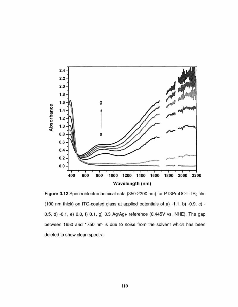
I • I ' I • I ' I • I • I ' I ' I • I
400 600 800 1000 1200 1400 1600 1800 2000 2200
Wavelength (nm)
Figure 3.12 Spectroelectrochemical data (350-2200 nm) for P13ProDOT-TB2 film
(100 nm thick) on ITO-coated glass at applied potentials of a) -1.1, b) -0.9, c) -
0.5, d) -0.1, e) 0.0, f) 0.1, g) 0.3 Ag/Ag+ reference (0.445V vs. NHE). The gap
between 1650 and 1750 nm is due to noise from the solvent which has been
deleted to show clean spectra.
110
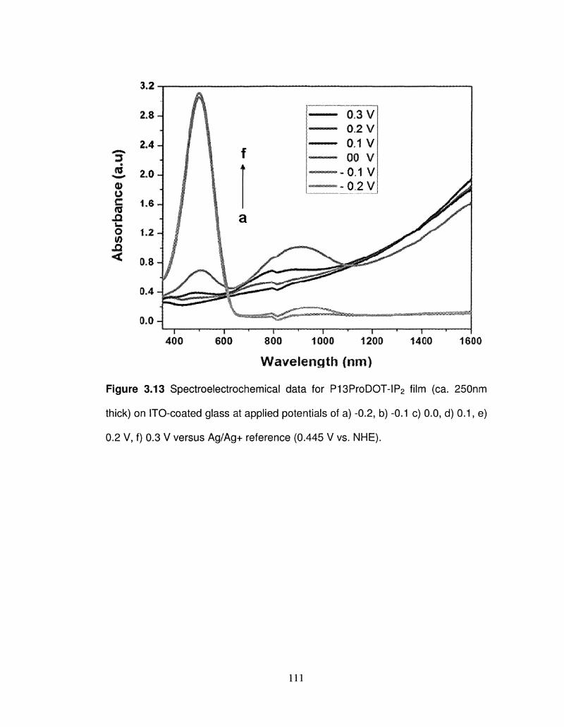
3.2
— I ' 1 -' 1 ", 1 " T """ 1 •'* 1
400 600 800 1000 1200 1400 1800
Wavelength (ran)
Figure 3.13 Spectroelectrochemical data for P13ProDOT-IP2 film (ca. 250nm
thick) on ITO-coated glass at applied potentials of a) -0.2, b) -0.1 c) 0.0, d) 0.1, e)
0.2 V, f) 0.3 V versus Ag/Ag+ reference (0.445 V vs. NHE).
I l l
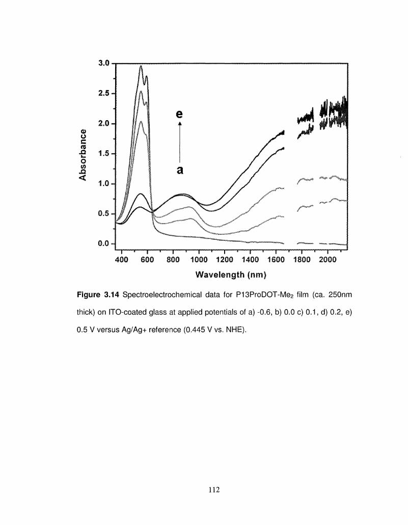
T_,»^^ ^ ^ y ^ ^ ^ 400 600 800 1000 1200 1400 1600 1800 2000
Wavelength (nm)
Figure 3.14 Spectroelectrochemical data for P13ProDOT-Me2 film (ca. 250nm
thick) on ITO-coated glass at applied potentials of a) -0.6, b) 0.0 c) 0.1, d) 0.2, e)
0.5 V versus Ag/Ag+ reference (0.445 V vs. NHE).
112
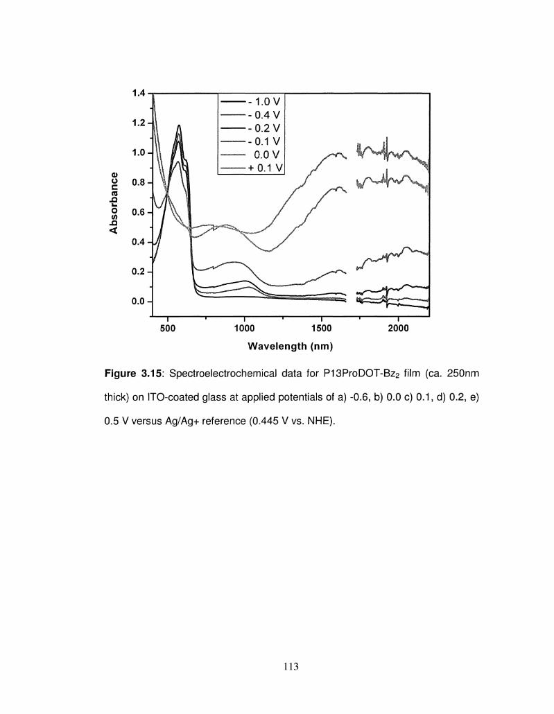
500 1000 1500
Wavelength (nm)
2000
Figure 3.15: Spectroelectrochemical data for P13ProDOT-Bz2 film (ca. 250nm
thick) on ITO-coated glass at applied potentials of a) -0.6, b) 0.0 c) 0.1, d) 0.2, e)
0.5 V versus Ag/Ag+ reference (0.445 V vs. NHE).
113
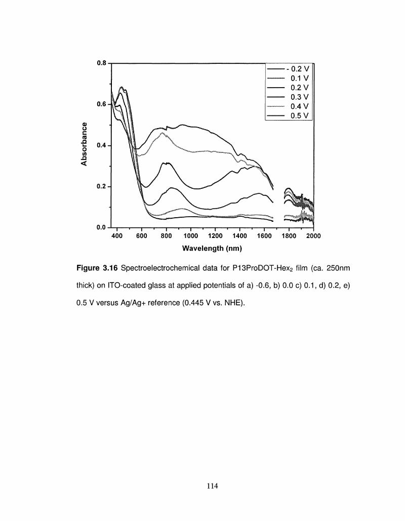
400 600 - i 1 1 1 1 1 1 1 1 1 1 , 1-
800 1000 1200 1400 1600 1800 2000
Wavelength (nm)
Figure 3.16 Spectroelectrochemical data for P13ProDOT-Hex2 film (ca. 250nm
thick) on ITO-coated glass at applied potentials of a) -0.6, b) 0.0 c) 0.1, d) 0.2, e)
0.5 V versus Ag/Ag+ reference (0.445 V vs. NHE).
114
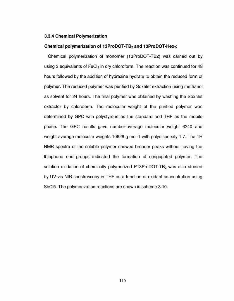
3.3.4 Chemical Polymerization
Chemical polymerization of 13ProDOT-TB2 and 13ProDOT-Hex2:
Chemical polymerization of monomer (13ProDOT-TB2) was carried out by
using 3 equivalents of FeCl3 in dry chloroform. The reaction was continued for 48
hours followed by the addition of hydrazine hydrate to obtain the reduced form of
polymer. The reduced polymer was purified by Soxhlet extraction using methanol
as solvent for 24 hours. The final polymer was obtained by washing the Soxhlet
extractor by chloroform. The molecular weight of the purified polymer was
determined by GPC with polystyrene as the standard and THF as the mobile
phase. The GPC results gave number-average molecular weight 6240 and
weight average molecular weights 10628 g mol-1 with polydispersity 1.7. The 1H
NMR spectra of the soluble polymer showed broader peaks without having the
thiophene end groups indicated the formation of congugated polymer. The
solution oxidation of chemically polymerized P13ProDOT-TB2 was also studied
by UV-vis-NIR spectroscopy in THF as a function of oxidant concentration using
SbCI5. The polymerization reactions are shown is scheme 3.10.
115
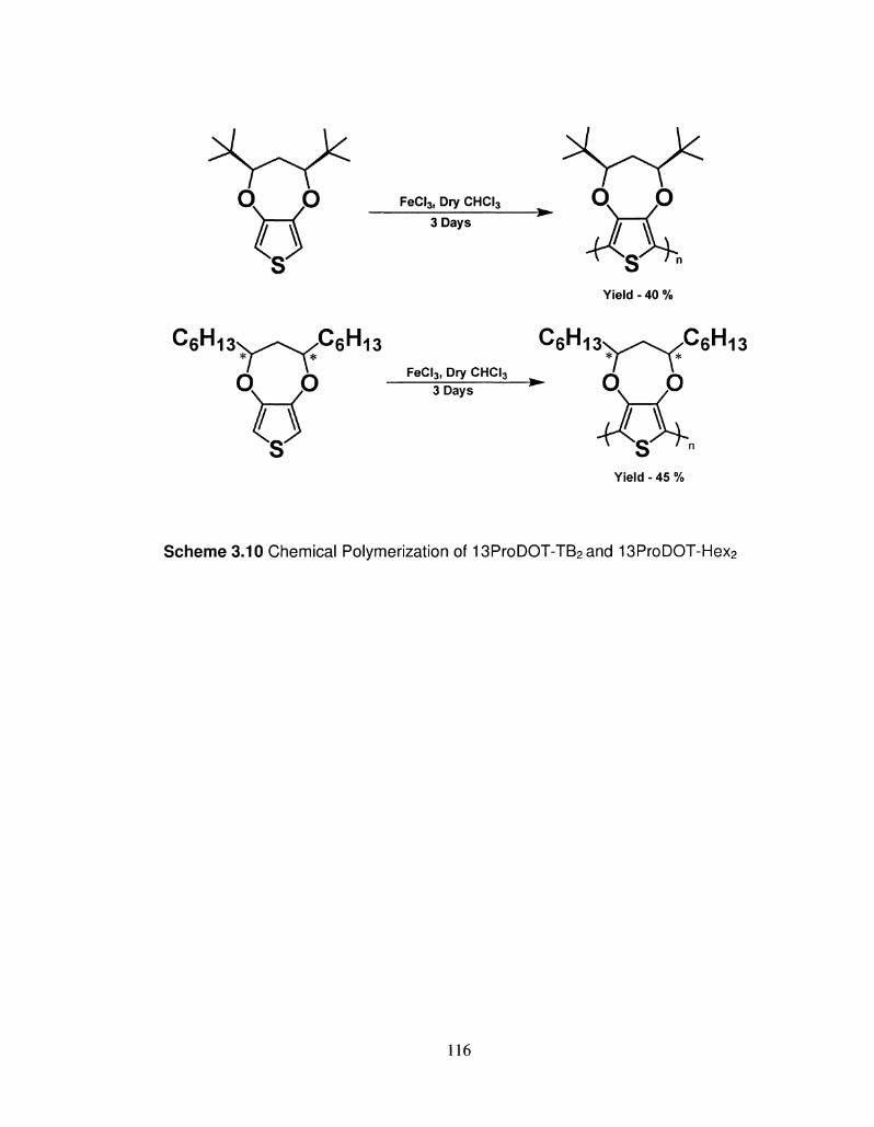
o o
9 FeCI3, Dry CHCI3
3 Days
CfiH 6 n 1 3 \ ^ - \ / ^ 6 r , 1 3
o o
9 FeCI3, Dry CHCI3
3 Days " ^ 0 \ _ / 0
Yield - 45 %
Scheme 3.10 Chemical Polymerization of 13ProDOT-TB2and 13ProDOT-Hex2
116
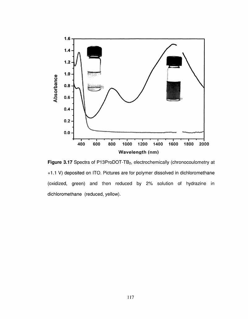
0 o W w o m <
0,2 H
"i * r 400 600
"1 * I * f r—T 800 1000 1200 1400 1800 1800 2000
Wavelength (nirt)
Figure 3.17 Spectra of P13ProDOT-TB2, electrochemically (chronocoulometry at
+1.1 V) deposited on ITO. Pictures are for polymer dissolved in dichloromethane
(oxidized, green) and then reduced by 2% solution of hydrazine in
dichloromethane (reduced, yellow).
117
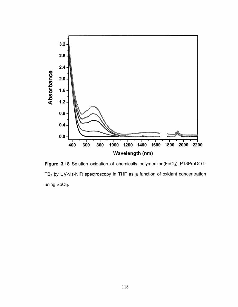
Abs
orba
nce
3.2-
2.8-
2.4-
2.0-
1.6-
1.2-
0.8-
0.4-
0.0- " ^ —""^Ifes^aBS^J ^ ^ - « ^ » * M ™ * ^ . . ^ . r J _ _ J J ^ . . . . . . ^ ^ . . . i ^ ^ ^ ^ ^ . „._,.... t.^ |
| 1 | 1 | 1 | 1 | 1 | . • • ! • • • • 400 600 800 1000 1200 1400 1600 1800 2000 2200
Wavelength (nm)
Figure 3.18 Solution oxidation of chemically polymerized(FeCI3) P13ProDOT-
TB2 by UV-vis-NIR spectroscopy in THF as a function of oxidant concentration
using SbCI5.
118
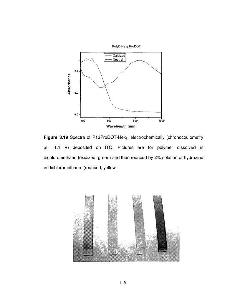
PolyDiHexylProDOT
0.0-
400
Oxidized Neutral
— i • 1— 600 800
Wavelength (nm)
1000
Figure 3.19 Spectra of P13ProDOT-Hex2, electrochemically (chronocoulometry
at +1.1 V) deposited on ITO. Pictures are for polymer dissolved in
dichloromethane (oxidized, green) and then reduced by 2% solution of hydrazine
in dichloromethane (reduced, yellow
"vrrlr \ ^ t ' i ;
119
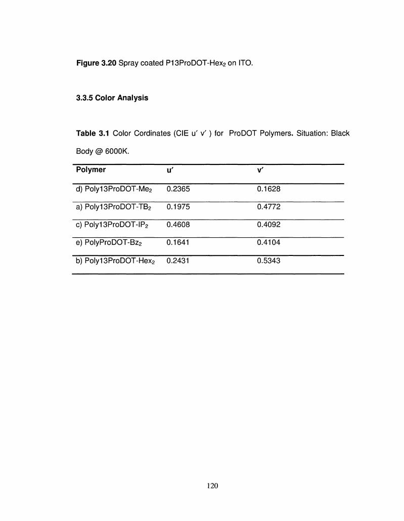
Figure 3.20 Spray coated P13ProDOT-Hex2 on ITO.
3.3.5 Color Analysis
Table 3.1 Color Cordinates (CIE u' v ' ) for ProDOT Polymers. Situation: Black
Body @ 6000K.
Polymer
d) Poly13ProDOT-Me2
a) Poly13ProDOT-TB2
c)Poly13ProDOT-IP2
e) PolyProDOT-Bz2
b)Poly13ProDOT-Hex2
u'
0.2365
0.1975
0.4608
0.1641
0.2431
V'
0.1628
0.4772
0.4092
0.4104
0.5343
120
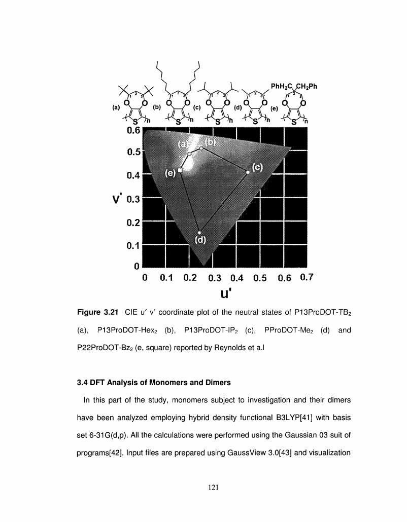
0 0.1 0.2 0.3 0.4 0.5 0.6 0.7
U'
Figure 3.21 CIE u' v' coordinate plot of the neutral states of P13ProDOT-TB2
(a), P13ProDOT-Hex2 (b), P13ProDOT~IP2 (c), PProDOT~Me2 (d) and
P22ProDOT-Bz2 (e, square) reported by Reynolds et a.l
3.4 DFT Analysis of Monomers and Dinners
In this part of the study, monomers subject to investigation and their dimers
have been analyzed employing hybrid density functional B3LYP[41] with basis
set 6-31G(d,p). All the calculations were performed using the Gaussian 03 suit of
programs[42]. Input files are prepared using GaussView 3.0[43] and visualization
121
of calculations results were done using the same program. All the structures of
the monomers were fully optimized without any geometrical restrictions. Full
optimization was checked by obtaining a vibrational spectrum without imaginary
frequencies. Optimized structures for the monomers 13ProDOT-TB2 and
ProDOT-Me2 are shown in Table 4. Both 13ProDOT-TB2 and ProDOT-Me2 have
symmetry Cs similar to unsubstituted ProDOT (its structure was optimized at the
same theory level but its geometry is not given in the figure). All four C atoms on
the thiophene part which will form conjugated backbone of polymer are in the
same plane for all the structures in this study. The oxygen atoms are nearly on
the same plane with the C atoms of thiophene ring for all the structures, since the
dihedral angle for C-C-C-0 is nearly same. Here, three C atoms belong to the
thiophene ring. The dihedral angle, defined with atoms of thiophene ring, C-C-C-
S, was the same for all the structures: -1.14, -1.07, -1.08 for ProDOT, ProDOT-
Me2 and 13ProDOT-TB2, respectively. The sulfur atom is slightly directed to the
same side as the C atoms to which the substituents are connected.
Since the valence and conduction bands are formed from the HOMOs and
LUMOs of the monomers on the chain, some predictions may be done on the
electronic properties of the polymers based on its monomers. HOMO and LUMO
energy levels of three monomers are given in Supporting Table 3. Having two
methyl substitution on the 2,2 positions causes nearly no differences in the
HOMO and LUMO energy levels. t-Butyl substitution into the 1,3 positions
causes a slightly larger effect, but approximately the same again. A 0.06 eV shift
in HOMO and LUMO energy levels occured, which resulted in the same energy
122
gap. So it may be concluded that experimental finding on the band gap
differences of polymers, given in this study, cannot be explained based simply on
the electronic properties of monomers, since all of them have approximately the
same electronic structure with nearly the same geometry. There must be another
factor causing the higher band gap value of P13ProDOT-TB2 with respect to
ProDOT-Me2.
Mean deviation from planarity affects also band gap value for the polymers[44].
The dihedral angle of dimers gives us enough qualitative information about
dihedral angles between consecutive units on the polymer chain. Thus, dimers of
the monomers studied in this work have been optimized with same method. Also
included was the dimer of 22ProDOT-TB2, which is a theoretical monomer (as no
one has synthesized it, to date) used as a comparison with calculations for
13ProDOT-TB2. The dimer of unsubstituted poly(ProDOT) was also optimized to
compare with these substituted ones. Optimized structures of the dimers are
given in Table 3.2. The dimer of unsubstituted poly(ProDOT) was not shown
since its structure is very similar to ProDOT-Me2. Both ProDOT and ProDOT-Me2
dimers have thiophene rings approximately in the same plane. But the dimer of
P13ProDOT-TB2 has a high deviation from planarity. The C-C-C-C dihedral
angle, including C atoms which are subject to inter-ring bonding is -76.1 degrees.
As seen from Table 3.3, HOMO and LUMO energy levels of ProDOT and
ProDOT-Me2 are nearly same. So substitution of methyl groups into the 2,2
position does not affect HOMO and LUMO energy levels. These values for
P13ProDOT-TB2 are rather different from previous ones. HOMO energy level is
123
lowered to -5.70 eV, since LUMO energy level is shifted to a higher value, -0.44
eV. This effect comes from the fact that t-butyl substituents cause twisting along
the backbone. The bond length between the thiophene rings is 1.446 and 1.445
A for ProDOT and ProDOT-Me2, respectively. This value is also altered as a
result of twisting and shifted to 1.458 A. The first C-C bond length after the inter
ring bond in the ring was 1.382 and 1.381 A for ProDOT and ProDOT-Me2,
respectively. This value is 1.377 A for 13ProDOT-TB2j shorter than that of other
dimers. The stretching of the inter-ring bond and shortening of the next bond in
the ring is a measure of decreasing conjugation and opening of the gap between
HOMO and LUMO energy levels. 13ProDOT-TB2 has 1.12 eV higher gap value
with respect to other dimers. This extends as the reason for the higher band gap
value of P13ProDOT-TB2 with respect to other polymers. When we compare this
value with that of the polymers measured, there are two factors which should be
considered. These factors cause reduction in the energy gap value as going from
dimer to polymer into the solid state phase. First, Hthe HOMO level is shifted to
higher value and LUMO level is shifted to lower value with increasing chain
length. Due to this reason, the energy gap is lowered for a longer polymer chain.
Second, the inter-chain interaction resulting in the reduction of band gap value of
polymer in a solid state form. Considering these two factors, it may be concluded
that the higher band gap value of P13ProDOT-TB2 with respect to PProDOT-Me2
is due to a deviation from planarity.
124
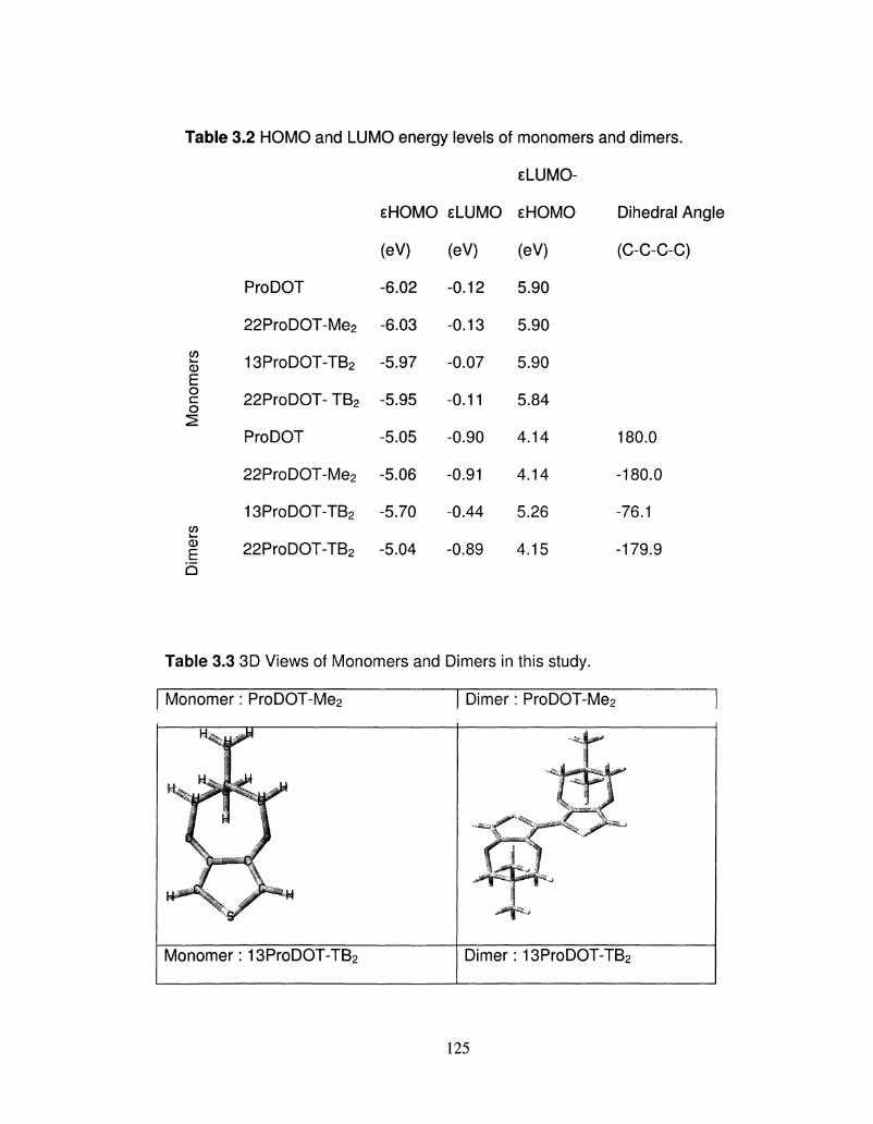
Table 3.2 HOMO and LUMO energy levels of monomers and dimers.
8LUMO-
(5 E o c o
J—
CD
E b
ProDOT
22ProDOT-Me2
13ProDOT-TB2
22ProDOT- TB2
ProDOT
22ProDOT-Me2
13ProDOT-TB2
22ProDOT-TB2
eHOMO
(eV)
-6.02
-6.03
-5.97
-5.95
-5.05
-5.06
-5.70
-5.04
E L U M O
(eV)
-0.12
-0.13
-0.07
-0.11
-0.90
-0.91
-0.44
-0.89
E H O M O
(eV)
5.90
5.90
5.90
5.84
4.14
4.14
5.26
4.15
Dihedral Angle
(C-C-C-C)
180.0
-180.0
-76.1
-179.9
Table 3.3 3D Views of Monomers and Dimers in this study.
Monomer: ProDOT-Me2 Dimer: ProDOT-Me2
•r ***. ; ^ ™ * *
jj&ffZ.j
Monomer: 13ProDOT-TB2 Dimer: 13ProDOT-TB2
125
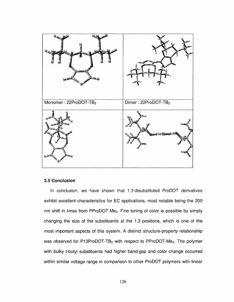
3.5 Conclusion
In conclusion; we have shown that 1,3-disubstituted ProDOT derivatives
exhibit excellent characteristics for EC applications, most notable being the 200
nm shift in Amax from PProDOT-Me2. Fine tuning of color is possible by simply
changing the size of the substituents at the 1,3 positions, which is one of the
most important aspects of this system. A distinct structure-property relationship
was observed for P13ProDOT-TB2 with respect to PProDOT-Me2. The polymer
with bulky t-butyl substituents had higher band-gap and color change occurred
within similar voltage range in comparison to other ProDOT polymers with linear
126
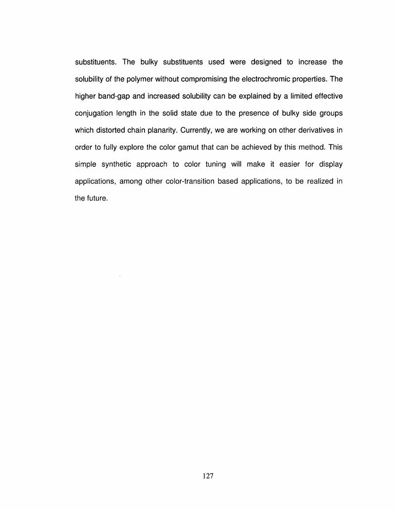
substituents. The bulky substituents used were designed to increase the
solubility of the polymer without compromising the electrochromic properties. The
higher band-gap and increased solubility can be explained by a limited effective
conjugation length in the solid state due to the presence of bulky side groups
which distorted chain planarity. Currently, we are working on other derivatives in
order to fully explore the color gamut that can be achieved by this method. This
simple synthetic approach to color tuning will make it easier for display
applications, among other color-transition based applications, to be realized in
the future.
127
3.6 References
1. Monk, P. M. S.; Mortimer, R. J.; Rosseinsky, D. R. in Electrochromism:
Fundamentals and Applications, Wiley-VCH, Weinheim, Germany 1995.
2. Dyer, A. L; Reynolds, J. R. in Handbook of Conducting Polymers. Conjugated
Polymers: Theory, Synthesis, Properties, and Characterization, 3nd ed. (Eds: T.
A. Skotheim, J. R. Reynolds), CRC Press, Boca Raton, FL, USA 2007, Ch. 20.
3. Mortimer, R. J. Chem. Soc. Rev. 1997, 26, 147.
4. Rosseinsky, D. R.; Mortimer, R. J. Adv. Mater. 2001, 13, 783.
5. McQuade, D. T.; Pullen, A. E.; Swager, T. M. Chem. Rev. 2000, 100, 2537.
6. Yang, J. S.; Swager, T. M. J. Am. Chem. Soc. 1998, 120, 11864.
7. Sotzing, G. A.; Briglin, S.; Grubbs, R. H.; Lewis, N. S. Anal. Chem. 2000, 72,
3181.
8. Ma, H.; Chen, .; Sassa, T.; Dalton, L. R.; Jen, A. K. Y. J. Am. Chem. Soc.
2001, 723,986.
9. Yu, G.; Heeger, A.J. Synth. Met. 1997, 85, 1183.
10. Ferraris, J. P.; Eissa, M. M.; Brotherston, I. D.; Loveday, D. C; Chem. Mater.
1998, 11, 3528.
11. Jonas, F.; Heywang, G.; Electrochim. Acta 1994, 39, 1345.
12. Perucki, M.; Chandrasekhar, P. Synth. Met. 2001, 119, 385.
13. Brabec, C. J.; Sariciftci, N. S.; Hummelen, J. C. Adv. Func. Mater. 2001, 11,
15.
14. Henckens, A.; Knipper, M.; Polec, I.; Manca, J.; Lutsen, L; Vanderzande, D.
Thin Solid Films 2004, 451 & 572.
128
15. Groenendaal, L; Jonas, F.; Freitag, D.; Pielartzik, H.; Reynolds, J. R.;
AdV.Mater. 2000, 12,481.
16. Sotzing, G. A.; Reynolds, J. R.; Steel, P.J. Adv. Mater. 1997, 9, 795.
17. Schwendeman, I.; Gaupp, C. L; Hancock, J. M.; Groenendaal, L; Reynolds,
J. R. Adv. Funct. Mater.2003, 13, 541.
18. Reeves, B. D.; Thompson, B. C; Abboud, K. A.; Smart, B. E.; Reynolds, J.
R. Adv. Mater. 2002, 74,717.
19. Sonmez, G.; Meng, H.; Wudl, F. Chem. Mater. 2004, 16, 574.
20. Groenendaal, L; Zotti, G.; Aubert, P. H.; Waybright, S. H.; Reynolds, J. R.
Adv. Mater. 2003, 15, 855.
21. Dietrich, M.; Heinze, J.; Heywang, G.; Jonas, F. J. Electroanal. Chem. 1994,
369, 87
22. Bokria, J. G.; Kumar, A.; Seshadri, V.; Tran, A.; Sotzing, G. A. Advanced
Materials, 2008, 20, 1175.
23. Invemale, M. A.; Ding, Y.; Mamangun, D. M. D.; Yavuz, M. S.; Sotzing, G. A.
Advanced Materials, 2010, 22, 1-4.
24. Welsh, D. M.; Kumar, A.; Morvant, M. C; Reynolds, J. R. Synth. Met. 1999,
102, 967;
25. Welsh, D. M.; Kloeppner, L. J.; Madrigal, L; Pinto, M. R.; Thompson, B. C;
Schanze, K. C; Abboud, K. A.; Powell, D.; Reynolds, J. R. Macromolecules,
2002,35,6517.
26. Kumar, A.; Welsh, D. M.; Morvant, M. C; Piroux, F.; Abboud, K. A.; Reynolds,
J. R. Chem. Mater. 1998, 10, 896.
129
27. Welsh, D. M.; Kumar, A.; Meijer, E. W.; Reynolds, J. R.; Adv. Mater. 1999,
11,1379
28. Kobayashi, H.; Cui, H. Chem. Rev. 2004, 104, 5265.
29. Krishnamoorthy, K.; Ambade, A. V.; Kanungo, M.; Contractor, A. C; Kumar,
A. J. Mater. Chem. 2001, 11, 2909
30. Yamabe, T.; Tanaka, K.; Koike, T.; Ueda, M. Molecular Crystals and Liquid
Crystals, 1985, 117, 185-92.
31. Wu, C. Q.; Zhang, Y. Z.; Lin, H. Q.; Synthetic Metals, 2001, 119, 219.
32. Dyer, A. L; Grenier, C. R. G.; Reynolds, J. R. Adv. Fund. Mater. 2007, 17,
1480.
33. Cho, S. I.; Kwon, W. J.; Choi, S.; Kim, P.; Park, S.; Kim, J.; Son, S. J.; Xiao,
R.; Kim, S.; Lee, S.B. Adv. Mater. 2005, 17, 171.
34. Meng, H.; Tucker, D.; Chaffins, S.; Chen, Y.; Helgeson, R.; Dunn, B.; Wudl,
F. Adv. Mater. 2003, 75,146.
35. Sapp, S. A.; Sotzing, G. A.; Reynolds, J. R. Chem. Mater. 1998, 10, 2101.
36. Sonmez, G.; Sonmez, H. B.; Shen, K. F.; Jost, R. W.; Rubin, Y.; Wudl, F.
Macromolecules, 2005, 38, 669.
37. Reeves, B. D.; Grenier, C. R. G.; Argun, A. A.; Cirpan, A.; McCarley, T. D.;
Reynolds, J. R. Macromolecules, 2004, 37, 7559.
38. Sonmez, G.; Sonmez, H. B.; Shen, K. F.; Jost, R. W.; Rubin, Y.; Wudl, F.
Angew.Chem. Int. Ed. 2004, 43, 1498.
39. Sonmez, G.; Sonmez, H. B.; Shen, K. F.; Jost, R. W.; Rubin, Y.; Wudl, F. Adv.
Mater. 2004, 16, 1905.
130
40. Suzuki, I.; Kin, H.; Yamamoto, Y. J. Am. Chem. Soc. 1993, 115,10139.
41. Becke, A. D. J. Chem. Phys.1993, 98, 5648
42. Lee, C; Yang, W.; Parr, R. G. Phys. RevB, 1988, 37, 785
43. Gaussian 03, Revision D.01
44. Roncali, J. Chem.Rev. 1997, 97, 173-205.
131
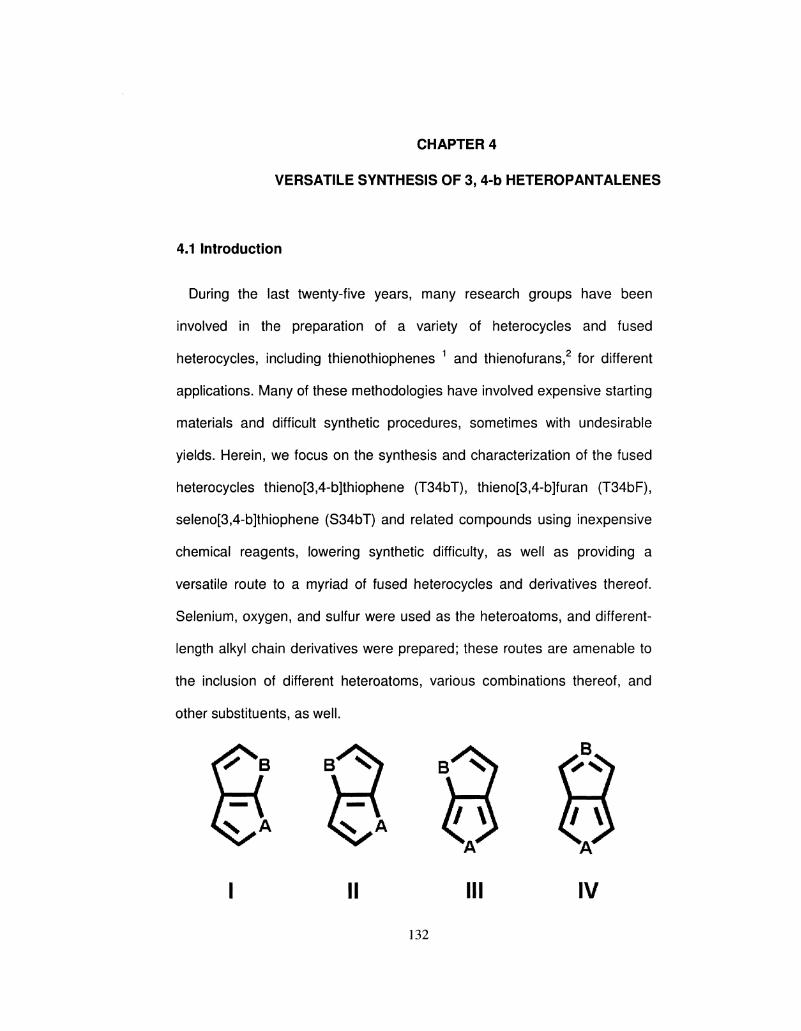
CHAPTER 4
VERSATILE SYNTHESIS OF 3, 4-b HETEROPANTALENES
4.1 Introduction
During the last twenty-five years, many research groups have been
involved in the preparation of a variety of heterocycles and fused
heterocycles, including thienothiophenes 1 and thienofurans,2 for different
applications. Many of these methodologies have involved expensive starting
materials and difficult synthetic procedures, sometimes with undesirable
yields. Herein, we focus on the synthesis and characterization of the fused
heterocycles thieno[3,4-b]thiophene (T34bT), thieno[3,4-b]furan (T34bF),
seleno[3,4-b]thiophene (S34bT) and related compounds using inexpensive
chemical reagents, lowering synthetic difficulty, as well as providing a
versatile route to a myriad of fused heterocycles and derivatives thereof.
Selenium, oxygen, and sulfur were used as the heteroatoms, and different-
length alkyl chain derivatives were prepared; these routes are amenable to
the inclusion of different heteroatoms, various combinations thereof, and
other substituents, as well.
I II III IV
132
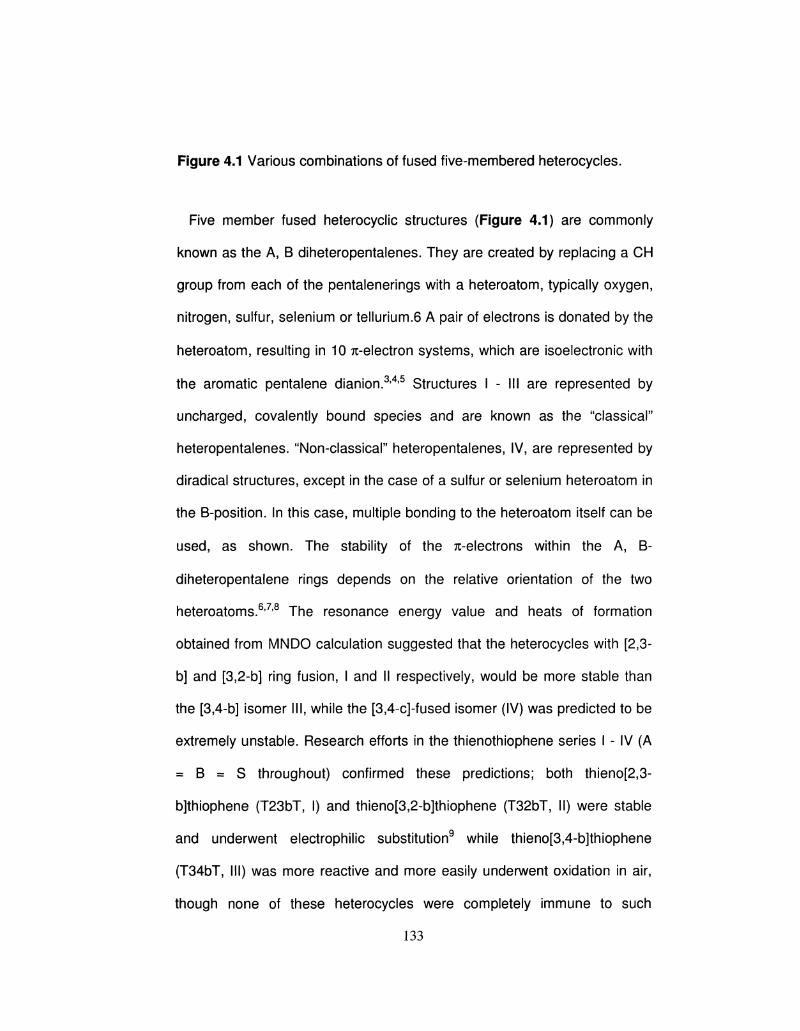
Figure 4.1 Various combinations of fused five-membered heterocycles.
Five member fused heterocyclic structures (Figure 4.1) are commonly
known as the A, B diheteropentalenes. They are created by replacing a CH
group from each of the pentalenerings with a heteroatom, typically oxygen,
nitrogen, sulfur, selenium or tellurium.6 A pair of electrons is donated by the
heteroatom, resulting in 10 7t-electron systems, which are isoelectronic with
the aromatic pentalene dianion.3,4,5 Structures I - III are represented by
uncharged, covalently bound species and are known as the "classical"
heteropentalenes. "Non-classical" heteropentalenes, IV, are represented by
diradical structures, except in the case of a sulfur or selenium heteroatom in
the B-position. In this case, multiple bonding to the heteroatom itself can be
used, as shown. The stability of the ^-electrons within the A, B-
diheteropentalene rings depends on the relative orientation of the two
heteroatoms.6'7,8 The resonance energy value and heats of formation
obtained from MNDO calculation suggested that the heterocycles with [2,3-
b] and [3,2-b] ring fusion, I and II respectively, would be more stable than
the [3,4-b] isomer III, while the [3,4-c]-fused isomer (IV) was predicted to be
extremely unstable. Research efforts in the thienothiophene series I - IV (A
= B = S throughout) confirmed these predictions; both thieno[2,3-
b]thiophene (T23bT, I) and thieno[3,2-b]thiophene (T32bT, II) were stable
and underwent electrophilic substitution9 while thieno[3,4-b]thiophene
(T34bT, III) was more reactive and more easily underwent oxidation in air,
though none of these heterocycles were completely immune to such
133
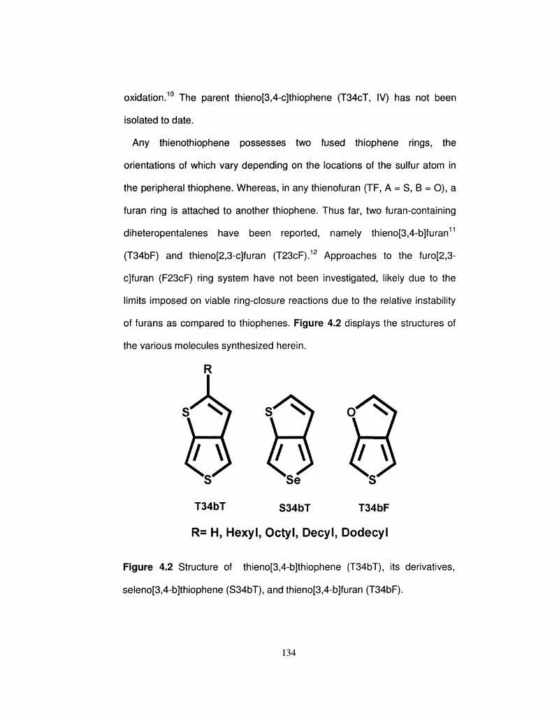
oxidation.10 The parent thieno[3,4-c]thiophene (T34cT, IV) has not been
isolated to date.
Any thienothiophene possesses two fused thiophene rings, the
orientations of which vary depending on the locations of the sulfur atom in
the peripheral thiophene. Whereas, in any thienofuran (TF, A = S, B = O), a
furan ring is attached to another thiophene. Thus far, two furan-containing
diheteropentalenes have been reported, namely thieno[3,4-b]furan11
(T34bF) and thieno[2,3-c]furan (T23cF).12 Approaches to the furo[2,3-
c]furan (F23cF) ring system have not been investigated, likely due to the
limits imposed on viable ring-closure reactions due to the relative instability
of furans as compared to thiophenes. Figure 4.2 displays the structures of
the various molecules synthesized herein.
T34bT S34bT T34bF
R= H, Hexyl, Octyl, Decyl, Dodecyl
Figure 4.2 Structure of thieno[3,4-b]thiophene (T34bT), its derivatives,
seleno[3,4-b]thiophene (S34bT), and thieno[3,4-b]furan (T34bF).
134
In the growing field of organic semiconductors, thiophene-based fused
heterocyclic materials play an important role. These materials display
promising optical and electrical properties for use in electrochromics,13
organic light-emitting diodes (OLEDs) 14 and organic photovoltaics
(OPVs).15 T34bT and T34bF are notable monomers as they can be used in
the preparation of intrinsically conducting, low band gap polymers. Indeed,
polymeric forms of T34bT have been used as conductors and as ion storage
layers for electrochromic devices.16'17 Derivatization of these heterocycles is
an effective method of property-tuning for the resultant polymers.
Limitations, with respect to derivatization, in the established syntheses of
these monomers have led to the development of the alternate routes
described herein.
In 1991, Brandsma18 reported the synthesis of T34bT via conversion of 3,4-
dibromothiophene to the monotrimethylsilyl acetylenic derivative, which was
then ring closed to form T34bT after forming the thiolate on the 3-position.
We reported a modified synthetic procedure where we obtained as high as
55-60% yield in the final ring closing step, however we were able to obtain a
maximum yield of only 8% using the conditions reported by Brandsma.19 In
1986, Moursounidi and coworkers first reported the synthesis of T34bF. For
many applications, derivatization at the 2-position is important, since the
substituent can affect the band gap and solubility of the resultant polymer.
This concept was shown by Pomerantz et al. with the synthesis of poly(2-
decylthieno[3,4-b]thiophene).20 Ferraris extended this concept by
introducing a phenyl group in the 2-position.21 Lu Ping Yu et al.22, has
135
synthesized T34bT with electron withdrawing ester groups in the 2-position;
however, thus far no one has reported substituents with an electron
donating character.
We were able to extend and expand the versatility of fused heterocycles by
our new routes. The alkyl substituents reported in this work are weak
electron donating groups, which will result in lower oxidation potentials for
polymerization. In addition, the lengthy alkyl groups will also contribute
towards making the resultant polymer organic soluble. Our use of the
selenium heteroatom was aimed at lowering the band gap.
The reported methods of making T34bT, 2-alkyl derivatized T34bT, and
T34bF23 require expensive chemicals such as 3,4-dibromothiophene and
3,6-di(pyridine-2'-yl)-s-tetrazine (DPT).24 This makes the polymers thereof
more costly, which is where the bulk of their applications lie. Moreover,
current synthetic procedures are limited because of the difficulty in
derivatizing the 2-position of T34bT. It is therefore necessary to develop
novel synthetic approaches for five-member fused heterocycles. We were
interested in developing a common synthetic methodology that combined
the strategies of T34bT with 2-alkyl T34bT to ultimately yield a series of 2-
substituted molecules. Further, we sought to incorporate another
heteroatom, selenium, into these fused to systems to explore the versatility
of our approach.
Synthetic schemes, including yields, for the new preparation of T34bT, its
derivatives, S34bT, and T34bF appear in Schemes 4.1-4.3. Scheme 4.1
shows the new synthesis for T34bT and S34bT, Scheme 4.2 shows the
136
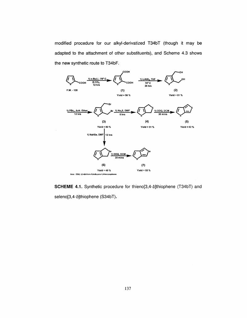
modified procedure for our alkyl-derivatized T34bT (though it may be
adapted to the attachment of other substituents), and Scheme 4.3 shows
the new synthetic route to T34bF.
COOH j-— OH
/ F \ ^ 1)n.BuLit-78°C f/V^ 1)LiAIHd,THF ^ //Xi J» \ / ^ C O O H 2)C02 ^ \ / ^ C O O H 7 0 ° C ^ \ / ^ ^
S 1 2 h r s S 24hrs S
F.W.-128 (1) (2)
Yield = 56 % Yield = 81 %
r-C* r-<^s r-^s ? r ^ / / \ \ ,Br 1 ) N a 2 S , D M F ^ / / \ \ / 1) DDQ, PCM w / / \ — /
\ y / 6h^ \ ' 30mins m X g /
(3) (4) (5)
Yield = 80 % Yield = 51 % Yield = 62 %
1)NaHSe, DMF 12 hrs
\ s / " " " ^ 30mins ^ \ ^
(6) (7)
Yield = 49 % Yield = 53 % Note: DDQ: 2,3-dichloro-5,6-dicyano-1,4-benzoquinone
SCHEME 4.1. Synthetic procedure for thieno[3,4-fo]thiophene (T34bT) and
seleno[3,4-i)]thiophene (S34bT).
137
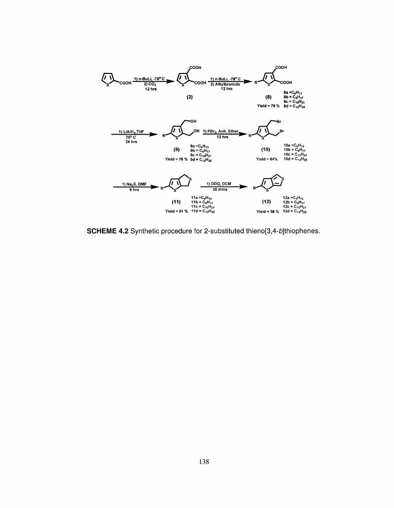
COOH COOH
/ / \ Y 1)n-BuLi,-78°C ^ / / \ V 1) n-BuLi, -78° C ^ Jj »\ N g X ^ C O O H 2)C0 2 • N g / ^ C O O H 2)Alkylbromide ^ R ^ s ^ 0 0 0 "
12hrs 12hrs 8a =C8Hi3
(2) (8) 8b = C8H17
8c = C10H21 Yield = 79% 8d = C12H25
1)LiAIH4,THF
••—OH r—Br
^ _ / / % V ^ 0 H 1)PBr3,Anh. Ether^^ / / \ V .B
- • R^SSX^/ ilh^ • R ^ % X ^ / 70° C ^ K ^S 1 2 h r s * ^S 24hrs
9a=C6H13 10a=C6H13 (9) 9b = C8H17 (10) 10b = C8H17
9c = C10H2i 10c = C10H21
Yield = 76% 9d = C12H25 Yield = 84% 10d = C12H25
1)Na2S, DMF w _ JJ M / 1) DDQ, PCM w / / \ — / ^ R ^ \ C X ^ 30"^ ^ R- XCX 6 hrs ^ R ^s 3 0 m , n s S*
11a=C6H13 12a=C6H13
(11) 11b = C8H17 (12) 12b = C8H17
11c = C10H21 12c = C10H21
Yield = 5 1 % 11d = C12H25 Yield = 58 % 12d = C12H25
SCHEME 4.2 Synthetic procedure for 2-substituted thieno[3,4-b]thiophenes.
138
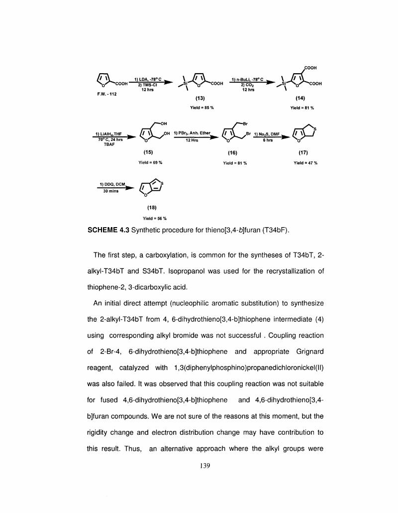
COOH
/ M A . 1)LDA,-78°C W \ J^\^ 1)n-BuLi,-78°C ^ \ J ^ \ ^ N Q X ^ C O O H 2)TMS-CI ^ ^ S i - ^ \ 0 / ^ C O O H 2) C0 2 • ^ S r ^ ^ C O O H
12hrs \ 12hrs \ F.W.-112
(13) (14)
Yield = 85 % Yield = 81 %
/ — O H y — B r
1)LiAIH4,THF ^ C ^ ^ ° H 1 ) P B r 3 ' A n h E t h e t ^ ( F \ ^ y B r 1) Na2S, DMF ^ / M A / 70°C,24hrs ^ N / ^ * " ^ 127te ^ N r * * ' ^ 6hr1 ^ \ r ^
TBAF
(15) (16) (17)
Yield = 69 % Yield = 81 % Yield = 47 %
1)DDQ, PCM H x ' #S
30 mins C# (18)
Yield = 56 %
SCHEME 4.3 Synthetic procedure for thieno[3,4-b]furan (T34bF).
The first step, a carboxylation, is common for the syntheses of T34bT, 2-
alkyl-T34bT and S34bT. Isopropanol was used for the recrystallization of
thiophene-2, 3-dicarboxylic acid.
An initial direct attempt (nucleophilic aromatic substitution) to synthesize
the 2-alkyl-T34bT from 4, 6-dihydrothieno[3,4-b]thiophene intermediate (4)
using corresponding alkyl bromide was not successful . Coupling reaction
of 2-Br-4, 6-dihydrothieno[3,4-b]thiophene and appropriate Grignard
reagent, catalyzed with 1,3(diphenylphosphino)propanedichloronickel(ll)
was also failed. It was observed that this coupling reaction was not suitable
for fused 4,6-dihydrothieno[3,4-b]thiophene and 4,6-dihydrothieno[3,4-
b]furan compounds. We are not sure of the reasons at this moment, but the
rigidity change and electron distribution change may have contribution to
this result. Thus, an alternative approach where the alkyl groups were
139
added after carboxylation step. Alkylation of thiophene-2, 3-dicarboxylic acid
was carried out by using different alkyl bromide in excess.Since the 5
position of 2-furoic acid is more reactive than the 3 position, protection of
the 5 position by TMS was necessary to obtain the 5-TMS-2,3-
furandicarboxylic acid. The reductions of corresponding dicarboxylic acids
were carried out by using LiAIH4. In the case of T34bF, deprotection of the
TMS group was carried out by using TBAF at the 2,3-furandiol step to
optimize the yield of the ring-closing reaction. The bromination of alcohols
was accomplished by using phosphorus tribromide (PBr3). 2,3-
Bis(bromomethyl)thiophene is not stable at room temperature; the white
solid became dark brown upon exposure to ambient conditions. A number of
different conditions and reagents were attempted for the ring closing of 2,3-
bis(bromomethyl)thiophene/furan with sulfur. The best results were obtained
by using sodium sulfide in a DMF solution. In the case of 4,6-
dihydroseleno[3,4-b]thiophene, the ring closing was done by using NaHSe
in a DMF solution. The intermediates 4,6-dihydrothieno[3,4-b]thiophene,
4,6-dihydroseleno[3,4-b]thiophene and 4,6-dihydrothieno[3,4-b]furan
decomposed upon standing at room temperature, which was minimized by
keeping them cold, at -50QC, at all times. The alkyl-substituted 4,6-
dihydrothieno[3,4-b]thiophene is stable at room temperature, however. The
last step, in each case, is a DDQ oxidation of the dihydro compounds; this
was carried out at 0°C for 30 minutes and progress was monitored by GC-
MS and TLC. Higher temperatures and longer reaction times lead to the
formation of dark, greenish-blue material that was insoluble in organic
140
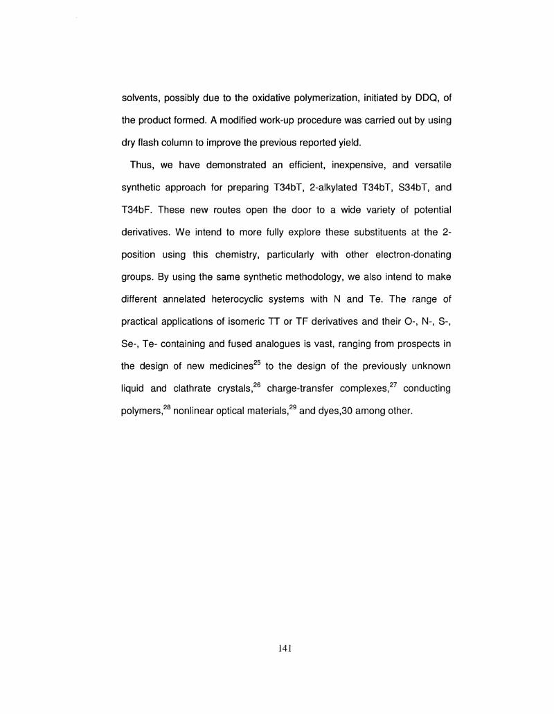
solvents, possibly due to the oxidative polymerization, initiated by DDQ, of
the product formed. A modified work-up procedure was carried out by using
dry flash column to improve the previous reported yield.
Thus, we have demonstrated an efficient, inexpensive, and versatile
synthetic approach for preparing T34bT, 2-alkylated T34bT, S34bT, and
T34bF. These new routes open the door to a wide variety of potential
derivatives. We intend to more fully explore these substituents at the 2-
position using this chemistry, particularly with other electron-donating
groups. By using the same synthetic methodology, we also intend to make
different annelated heterocyclic systems with N and Te. The range of
practical applications of isomeric TT or TF derivatives and their 0-, N-, S-,
Se-, Te- containing and fused analogues is vast, ranging from prospects in
the design of new medicines25 to the design of the previously unknown
liquid and clathrate crystals,26 charge-transfer complexes,27 conducting
polymers,28 nonlinear optical materials,29 and dyes,30 among other.
141
4.2 Synthesis and Characterization of thieno[3,4-b]thiophene and
Seleno[3, 4-b]thiophene:
COOH r^-ow
[ T \ 1)n-BuLi,-78°C fi\i 1)LiAIH„THF ^ /Tx^ JDH
1 2 h r s 24hrs
F.W.-128 (1) (2)
Yield = 56 % Yield = 81 %
1 )PBr 3 ,Anh .E ther^ / / \ \ Br 1) Na2S, DMF ^ / / \ \ / 1) DDQ, PCM ^ / / \ — /
12hrs ^ s ^ ^ ^ 6 ^ ^ ^ V " ^ " " ^ 30mins ^ \ ^
(3) (4) (5)
Yield = 80 % Yield = 51 % Yield = 62 %
1)NaHSe,DMF 12 hrs
y 7 \ \ / DDDQ.DCM^ / / \ — / X g ^ " " - 30mins ^ \ ^
(6) (7)
Yield = 49 % Yield = 53 %
Note : DDQ: 2,3-dichloro-5,6-dicyano-1,4-benzoquinone
Thiophene-2, 3-dicarboxylic acid (1): To a solution of thiophene-2-
carboxylic acid ( 20 g, 156 mmol), in anhydrous THF (500 mL), at -78QC was
added a 2.5 M solution of n-BuLi in hexane (137.2 mL, 342 mmol) over a
period of 90 mins. The reaction was allowed to stir at -78QC for another 30
mins at which time it was quenched with C02. Upon addition of C02, the
reaction became very thick and required some shaking for efficient mixing.
The reaction was allowed to warm at room temperature and stirring
continued for another 8 hrs. The reaction was quenched by 200 mL of water
and 80% of THF was removed by using a rotovap. The aqueous layer was
142
acidified with dilute HCI (until cloudy) and kept for 4 hrs. The crude acid was
precipitated out from the aqueous layer, filtered and dried. The crude acid
solid was recrystallized from isopropanol to obtain pure 1 (14.2 g, 56%
yield), which was confirmed by 1H-NMR, 13C-NMR and Melting Point.
Compound 1: 1H-NMR (500 MHz, DMSO-d6): 7.40(1 H, d, J = 5.1 Hz),
7.84(1 H, d, J = 5.1 Hz), 12.38 (2 H, br); 13C-NMR (500 MHz, DMSO-d6):
164.34, 164.14, 141.39, 140.03, 137.48, 129.59; Mp 270-272QC.
2, 3-Bis(hydroxymethyl)thiophene (2): To a slurry of LiAIH4 (16.5 g, 434
mmol), in THF (500 mL) at 0QC, under an atmosphere of nitrogen, was
added thiophene-2, 3-dicarboxylic acid (1, 15 g, 87.2 mmol). The reaction
was allowed to warm to 70QC and was stirred for another 24 hrs. After 24
hrs the reaction flask was kept in an ice bath and then 50 mL of diethyl ether
was added followed by the addition of 15 mL of water and 15 mL of 10%
NaOH solution. Addition of water was drop-wise. The organic layer was
dried over MgSCU, filtered and the filtrate concentrated to a crude solid 2
(10.1 g, 75 % yield) confirmed by 1H-NMR, 13C-NMR, GC-MS.
Compound 2 : 1H-NMR (500 MHz,CDCI3): 7.20 (1H, d, J = 5.1 Hz), 6.99
(1H, d ,J = 5.1 Hz), 4.65 (2 H, s), 4.52 (2 H, s), 4.2 (2 H, br); 13C-NMR (500
MHz,CDCI3): 140.88, 139.53, 129.32, 124.4, 58.94, 57.84; GC-MS (m/z):
128.
2, 3-Bis(bromomethyl)thiophene (3): To a solution of 2, 3-
143
bis(hydroxymethyl)thiophene (2, 10 g, 69.4 mmol) in anhydrous ether (400
mL) at 0QC, under a nitrogen atmosphere, was added PBr3 (9.8 mL, 104
mmol) drop-wise over a period of 15 mins. The reaction was continued for
another 6 hrs at room temperature and quenched by adding 50 mL of water.
The organic layer was extracted 4-5 times with water until the pH became
neutral. The organic layer was dried over MgS04, filtered and the filtrate
concentrated to a white solid 3 (15 g, 80% yield) confirmed by 1H-NMR, 13C-
NMR, GC-MS.
Compound 3: 1H-NMR (500 MHz,CDCI3): 7.27 (1H, d, J = 5.2 Hz), 7.01 (1H,
d , J = 5.2 Hz), 4.75 (2 H, s), 4.54 (2 H, s), 4.2 (2 H, br); 13C-NMR (500
MHz,CDCI3): 137.68, 137.24, 129.82, 126.27, 24.31, 23.76; GC-MS (m/z):
270.
Dihydrothieno[3,4-fo]thiophene (4): To a solution of sodium sulfide
nonahydrate (8.9 g, 37 mmol) in DMF (100 mL) at 30QC under a nitrogen
atmosphere, was added 2,3 bis(bromomethyl)thiophene (3, 10 g, 37 mmol)
solution in DMF (300 mL). 2, 3Bis(bromomethyl)thiophene addition was very
slow and the temperature monitored to gradually increase from 30QC to
70QC. The reaction was continued for another 12 hrs at 70QC during which
time the contents became dark in color. The product was extracted in diethyl
ether (200 mL) and washed with sufficient water to remove DMF. The
organic layer was dried over MgS04, filtered and the filtrate concentrated to
a crude dark brown liquid 4 (2.6 g, 51% yield). The product was confirmed
144
by 1H-NMR, 13C-NMR and GC-MS.
Compound 4: 1H-NMR (500 MHz, CDCI3): 7.27 (1H, d), 6.75 (1H, d), 4.16
(2H, s), 4.04 (2 H, s); 13C-NMR (500 MHz, CDCI3): 144.31, 139.93, 130.01,
123.39, 33.63, 33.52; GC-MS (m/z): 142;
Thieno[3,4-t»]thiophene (5): Dihydrothieno [3,4-b]thiophene (4, 2.0 g, 14
mmol) and anhydrous methylene chloride (100 mL) were taken in a dry 3-
neck flask, and cooled the solution to 0°C before adding 2,3-dichloro5,6-
dicyano-1,4-benzoquinone (DDQ, 3.17 g, 14 mmol). The reaction mixture
was stirred at 0°C for 30 minutes, and then passed through the silica. After
evaporating the solvent, the product was purified by liquid chromatography
using petroleum ether as an eluent. The purified thieno[3,4-£)]thiophene 5
was obtained (1.2 g, 62 % yield). The final product was confirmed by 1H-
NMR, 13C-NMR, GC-MS and FTIR.
Compound 5: 1H-NMR (500 MHz, CDCI3): 7.37 (1H, d), 6.95 (1H, dd), 7.27
(1H, dd), 7.36 (1H, d); 13C-NMR (500 MHz, CDCI3): 148.21, 140.00, 132.79,
117.19, 112.01, 110.98; GC-MS (m/z): 140; FTIR (liquid film): 3110 (w),
3070 (w), 2923 (w), 2850 (w), 2340 (w), 1732 (s), 1554 (s), 1490 (s), 1383
(w), 1020 (w), 770 (m), 665 (m) cm"1.
Dihydroseleno[3,4-b]thiophene (6): To a freshly prepared solution of
sodium hydrogen selenide7 in DMF (100 mL) at 30SC under a nitrogen
145
atmosphere, was added 2, 3 bis(bromomethyl)thiophene (3, 4 g, 14.8 mmol)
solution in DMF (200 ml_). 2, 3Bis(bromomethyl)thiophene addition was very
slow and the temperature monitored to gradually increase from 30QC to
50QC. The reaction was continued for another 12 hrs at 70QC during which
time the contents became dark in color. The product was extracted in diethyl
ether (200 mL) and washed with sufficient water to remove DMF. The
organic layer was dried over MgS04, filtered and the filtrate concentrated to
a crude dark brown liquid 4 (1.37 g, 49 % yield). The product was
confirmed by 1H-NMR, GC-MS. The compound decomposed during the 13C
NMR.
Compound 7: 1H-NMR (400 MHz, CDCI3): 7.04 (1H, d), 6.89 (1H, dd), 3.68
(2H, s), 3.50 (2 H, s); GC-MS (m/z): 190;.
Selono[3,4-b]thiophene (7): Dihydroselono[3, 4-b]thiophene (6, 1.0 g, 5.2
mmol) and anhydrous methylene chloride (40 mL) were taken in a dry 3-
neck flask, and cooled the solution to 0°C before adding 2, 3-dichloro5,6-
dicyano-1,4-benzoquinone (DDQ, 1.2 g, 5.2 mmol). The reaction mixture
was stirred at 0°C for 30 minutes, and then passed through the silica. After
evaporating the solvent, the product was purified by liquid chromatography
using petroleum ether as an eluent. The purified seleno[3,4-b]thiophene 7
was obtained (0.52 g, 53 % yield). The final product was confirmed by 1H-
NMR, 13C-NMR, 77Se- NMR and GC-MS.
146
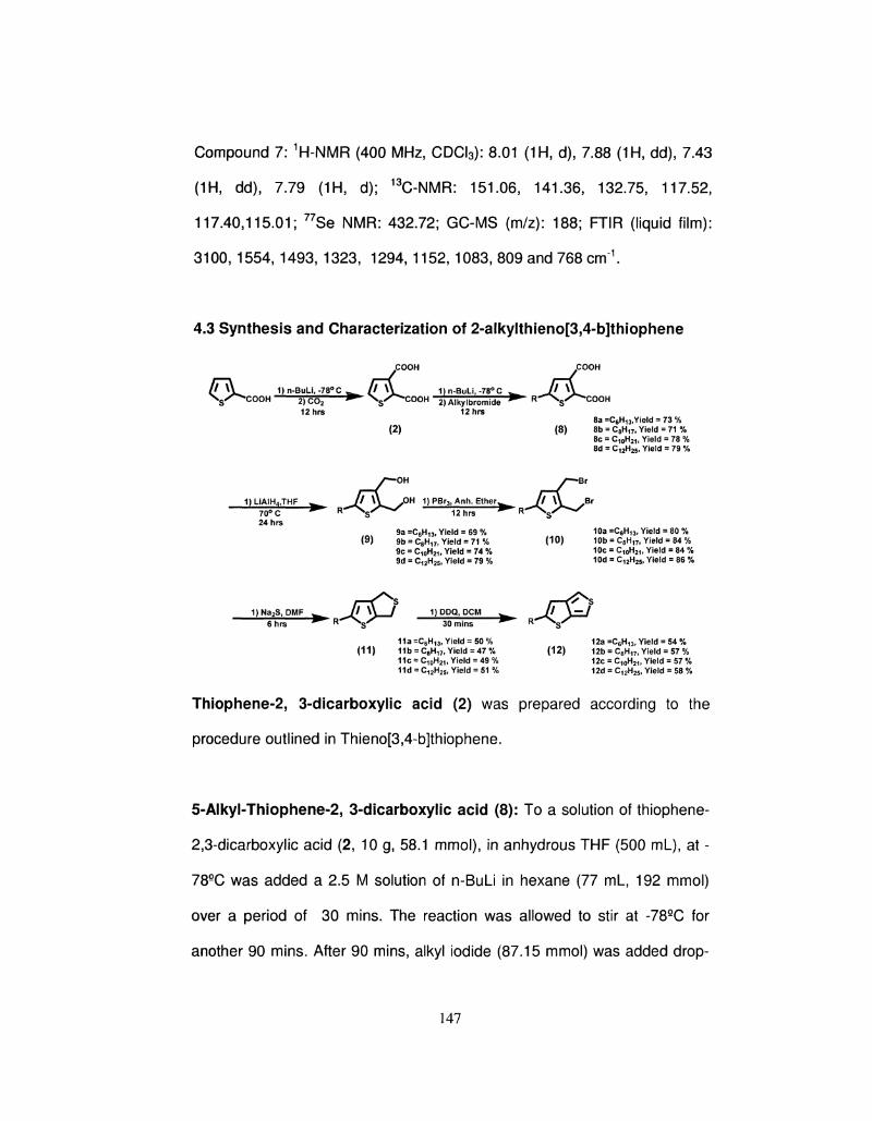
Compound 7: 1H-NMR (400 MHz, CDCI3): 8.01 (1H, d), 7.88 (1H, dd), 7.43
(1H, dd), 7.79 (1H, d); 13C-NMR: 151.06, 141.36, 132.75, 117.52,
117.40,115.01; 77Se NMR: 432.72; GC-MS (m/z): 188; FTIR (liquid film):
3100, 1554, 1493, 1323, 1294, 1152, 1083, 809 and 768 cm1.
4.3 Synthesis and Characterization of 2-alkylthieno[3,4-b]thiophene
COOH COOH
U ^ 1 )n -BuLi , -78°C^ / M V 1) n-BuLi, -78° C w / / \ \ N s / ^ C O O H 2)CO; • \ s / ^ C O O H 2)Alkylbromide ^ R ^ N j ^ C O O H
12hrs 12hrs 8a =C6H13,Yield = 73 %
(2) (8) 8b = C8H17, Yield = 71 % 8c = C10H21, Yield = 78 % 8d = C12H25, Yield = 79 %
1) LiAIH4,THF
yT—OH y — B r
^ / / \ \ ^OH 1)PBr3,Anh. E t h e r ^ / / \ Y „ B r
70° C ^ K ^s 12hrs
9a =C6H13( Yield = 69 % 10a =C6H13, Yield = 80 % (9) 9b = C8H17lYield = 7 1 % (10) 10b = C8H17, Yield = 84 %
9c = C10H2i, Yield = 74 % 10c = C10H21, Yield = 84 % 9d = C12H25f Yield = 79 % 10d = C12H25, Yield = 86 %
1)Na2S, DMF ^ _ f M \ / 1) DDQ, PCM w Jj\zzJ ^ R ^ ^ y ^ 3 0 ^ ^ R ^ N ^ 6 hrs R S 3 0 m i n s
11a =C6H13, Yield = 50 % 12a =C6H13, Yield = 54 % (11) 11b = C8H17> Yield = 47% (12) 12b = C8H17) Yield = 57 %
11c = C10H21, Yield = 49 % 12c = C10H21l Yield = 57 % 11d = C12H25, Yield = 51 % 12d = C12H25, Yield = 58 %
Thiophene-2, 3-dicarboxylic acid (2) was prepared according to the
procedure outlined in Thieno[3,4-b]thiophene.
5-Alkyl-Thiophene~2, 3-dicarboxylic acid (8): To a solution of thiophene-
2,3-dicarboxylic acid (2, 10 g, 58.1 mmol), in anhydrous THF (500 ml_), at -
78QC was added a 2.5 M solution of n-BuLi in hexane (77 ml_, 192 mmol)
over a period of 30 mins. The reaction was allowed to stir at -78QC for
another 90 mins. After 90 mins, alkyl iodide (87.15 mmol) was added drop-
147
wise and the reaction continued for another 8 hrs at room temperature. The
reaction was quenched by adding 10 mL of water. Approximately 80% THF
was removed and made the aqueous layer basic by dilute NaOH solution
(color: Red-Orange). The aqueous layer was extracted twice with diethyl
ether to remove excess alkyl iodide which is soluble in ether. The cloudy
yellow aqueous layer was acidified with dilute HCI and extracted with diethyl
ether until the aqueous layer became clear. The organic layer was washed
with plenty of water to remove excess HCI. The combined organic layers
were dried over MgS04 and concentrated to a crude orange solid 8. No
purification was required in this step.
Compound 8a: 1H-NMR (500 MHz, DMSO-d6): 12.03 (br s, 2H), 7.13 (s, 1H),
2.67 (t, 2 H), 1.58 (m, 2 H), 1.25-1.15 (m, 6 H), 0.85 (t, 3 H). 13C-NMR (500
MHz, DMSO-d6): 164.55, 164.09, 146.53, 142.52, 137.70, 129.80, 31.91,
31.58, 30.28, 29.65, 22.56, 14.06.
Compound 8b: 1H NMR (500 MHz, DMSO-d6) 5 12.03 (br s, 2H), 7.14 (s,
1H), 2.76 (t, 2 H),1.59 (m, 2 H), 1.34-1.14 (m, 10H), 0.84 (t, 3 H). 13C-NMR
(500 MHz, DMSO-de) 164.54, 164.06, 146.46, 142.03, 137.58, 129.69,
31.75, 31.17, 29.73, 29.70, 29.65, 29.48, 22.58, 14.30.
Compound 8c: 1H NMR (500 MHz, DMSO-d6) 5 12.03 (br s, 2H), 7.15 (s,
1H), 2.77 (t, 2 H),1.59 (m, 2 H), 1.34-1.14 (m, 12 H), 0.84 (t, 3 H). 13C-NMR
(500 MHz, DMSO-d6) 164.55, 164.06, 146.46, 142.03, 137.58, 129.69,
148
31.75, 31.17, 29.73, 29.70, 29.67, 29.46, 29.39, 29.14, 22.56, 14.32.
Compound 8d: 1H-NMR (500 MHz, DMSO-d6): 11.99 (brs, 2H), 7.13 (s, 1H),
2.68 (t, 2 H), 1.56 (m, 2 H), 1.26-1.17 (m, 12 H), 0.85 (t, 3 H); 13C-NMR (500
MHz, DMSO-de) 164.54, 164.04, 146.46, 142.03, 137.58, 129.69, 31.75,
31.17, 29.73, 29.70, 29.67, 29.65, 29.48, 29.46, 29.39, 29.14, 22.53, 14.34.
FTIR: 3650 (w), 3600-3000 (b), 2952, 2925, 2852, 1571, 1524, 1465, 1435,
1377, 1347, 1171, 1086, 1023, 837, 814, 744, 691, 503 cm-1.
5-Alkyl-2, 3-Bis(hydroxymethyl)thiophene (9): To a slurry of LiAIH4 (7.5
g, 195 mmol), in THF (400 mL) at 09C, under an atmosphere of nitrogen,
was added 5alkyl-thiophene-2-3-dicarboxylic acid (8, 39 mmol). The
reaction was allowed to warm to 70QC and was stirred for another 24 hrs.
After 24 hrs the reaction flask was kept in ice bath and then 50 mL of diethyl
ether was added followed by the addition of 15 mL of water and 15 mL of 10
% NaOH solution. Addition of water was drop-wise. The organic layer was
dried over MgS04, filtered and the filtrate concentrated to a crude solid 9,
confirmed by 1H-NMR, 13C-NMR and GC-MS.
Compound 9a: 1H-NMR (500 MHz, CDCI3): 6.70 (s, 1H), 4.68 (s, 2H), 4.58
(s, 2 H), 2.72 (t, 2H), 1.64 (m, 2 H), 1.37-1.23 (m, 18 H), 0.89 (t, 3 H). 13C-
NMR (500 MHz, CDCI3): 145.27, 139.35, 137.51, 126.43, 59.40, 58.16,
31.Q1, 31.58, 30.28, 29.65, 22.56, 14.06; GC-MS (m/z): 228.
149
Compound 9b: 1H-NMR(500 MHz, CDCI3): 6.66(s, 1H), 4.66 (s, 2H), 4.55 (s,
2 H), 2.73 (t, 2H), 1.62 (m, 2 H), 1.39-1.16 (m, 10 H), 0.88 (t, 3 H) 13C-NMR
(500 MHz, CDCI3): 145.31, 139.40, 137.48, 126.36, 59.39, 58.12, 32.40,
32.10, 30.47, 30.14, 30.04, 29.84, 23.17, 14.48; GC-MS (m/z): 256.
Compound 9c: 1H-NMR(500 MHz, CDCI3): 6.66(s, 1H), 4.66 (s, 2H), 4.55 (s,
2 H), 2.73 (t, 2H), 1.62 (m, 2 H), 1.40-1.14 (m, 12 H), 0.88 (t, 3 H). 13C-NMR
(500 MHz, CDCI3): 145.29, 139.41, 137.46, 126.31, 59.35, 58.11, 32.40,
32.10, 30.48, 30.14, 30.04, 30.01, 29.85, 29.60, 23.17, 14.50; GC-MS (m/z):
284.
Compound 9d: 1H-NMR(500 MHz, CDCI3): 6.68 (s, 1H), 4.70 (s, 2H), 4.60 (s,
2 H), 2.73 (t, 2H), 1.63 (m, 2 H), 1.34-1.28 (m, 18 H), 0.86 (t, 3 H). 13C-NMR
(500 MHz, CDCI3): 145.31, 139.41, 137.46, 126.31, 59.35, 58.11, 32.40,
32.10, 30.47, 30.14, 30.04, 30.02, 29.84, 29.83, 29.60, 23.17, 14.50; GC-
MS (m/z): 312.
5-Alkyl-2, 3-Bis(bromomethyl)thiophene (10): To a solution of 5-alkyl-2,3
bis(hydroxymethyl) thiophene (9, 43 mmol) in anhydrous ether (300 mL) at
0SC, under a nitrogen atmosphere, was added PBr3 (6.15 mL, 65.7 mmol)
drop-wise over a period of 15 mins. The reaction was continued for another
6 hrs at room temperature and quenched by adding 50 mL of water. The
organic layer was extracted 4-5 times with water until the pH became
150
neutral. The organic layer was dried over MgSCU, filtered and the filtrate
concentrated to a crude solid 10, confirmed by 1H-NMR 13C-NMR and GC-
MS.
Compound 10a: 1H-NMR (500 MHz, CDCI3) 5 6.67(s, 1H), 4.69 (s, 2H), 4.45
(s, 2 H), 2.70 (t, 2H), 1.62 (m, 2 H), 1.40-1.25 (m, 6 H), 0.86 (t, 3 H). 13C-
NMR: (500 MHz, CDCI3): 147.21, 136.78, 134.80, 129.68, 126.47, 126.11,
31.80, 31.47, 30.17, 29.54, 22.45, 13.95; GC-MS (m/z): 354.
Compound 10b: 1H-NMR (500 MHz, CDCI3) 5 6.68(s, 1H), 4.70 (s, 2H), 4.46
(s, 2 H),2.73 (t, 2H), 1.64 (m, 2 H), 1.14-1.40 (m, 12 H), 0.88 (t, 3 H). 13C-
NMR: 147.32, 136.89, 134.85, 129.75, 126.63, 126.22, 32.33, 32.03, 30.40,
30.07, 29.77, 29.53, 23.10, 14.20; GC-MS (m/z): 382.
Compound 10c: 1H-NMR(500 MHz, CDCI3) 5 6.68(s, 1H), 4.70 (s, 2H), 4.46
(s, 2 H),2.73 (t, 2H), 1.64 (m, 2 H), 1.14-1.40 (m, 12 H), 0.88 (t, 3 H). 13C-
NMR: 147.30, 136.89, 134.91, 129.79, 126.58, 126.22, 32.33, 32.03, 30.40,
30.07, 29.97, 29.95, 29.76, 29.53, 23.10, 14.40; GC-MS (m/z): 410.
Compound 10d: 1H-NMR(500 MHz, CDCI3) 5 6.67(s, 1H), 4.69 (s, 2H), 4.45
(s, 2 H), 2.70 (t, 2H), 1.62 (m, 2 H), 1.40-1.25 (m, 18 H), 0.86 (t, 3 H). 13C-
NMR: 147.32, 136.89, 134.91, 129.79, 126.58, 126.22, 32.33, 32.03, 30.40,
30.07, 29.97, 29.95, 29.77, 29.76, 29.53, 23.10, 14.40; GC-MS (m/z): 438.
151
2-Alkyl-dihydrothieno[3,4-i)]thiophene (11): To a solution of sodium
sulfide nonahydrate (6.7 g, 28 mmol) in DMF (300 mL) at 30eC under a
nitrogen atmosphere, was added 5-alkyl-2,3 bis(bromomethyl)thiophene
(10, 28.2 mmol) solution in DMF (100 mL). 5-Alkyl-2,3
bis(bromomethyl)thiophene addition was very slow and the temperature
monitored to gradually increase from 30 eC to 70 SC. The reaction was
continued for another 12 hrs at 70 SC during which time the contents
became dark in color. The product was extracted in diethyl ether (200 mL)
and washed with sufficient water to remove DMF. The organic layer was
dried over MgSCU, filtered and the filtrate concentrated to a crude dark
brown liquid 11, confirmed by 1H-NMR,13C-NMR and GC-MS.
Compound 11a: 1H NMR(500 MHz, CDCI3) 5 6.45(s, 1H), 4.11 (t, 2H), 3.99
(t, 2 H), 2.72 (t, 2H), 1.63 (m, 2 H), 1.35-1.25 (m, 6 H), 0.86 (t, 3 H). 13C
NMR (500 MHz, CDCI3): 151.30, 143.10, 136.43, 119.11, 34.22, 33.99,
31.70, 31.37, 30.07, 29.44, 22.35, 14.01; GC-MS (m/z): 226.
Compound 11b: 1H NMR (500 MHz, CDCI3) 8 6.45(s, 1H), 4.11 (t, 2H), 3.99
(t, 2 H), 2.72 (t, 2H), 1.63 (m, 2 H), 1.35-1.26 (m, 10 H), 0.88 (t, 3 H). 13C
NMR (500 MHz, CDCI3): 151.35, 143.11, 136.52, 119.21, 34.22, 34.07,
32.42, 32.12, 30.49, 30.04, 29.85, 29.62, 23.19, 14.47 GC-MS (m/z): 254.
Compound 11c: 1H NMR(500 MHz, CDCI3) 5 6.45(s, 1H), 4.12 (t, 2H), 4.00
(t, 2 H), 2.72 (t, 2H), 1.64 (m, 2 H), 1.14-1.40 (m, 12 H), 0.88 (t, 3 H). 13C
152
NMR (500 MHz, CDCI3): 151.38, 143.12, 136.53, 119.22, 34.22, 34.09,
32.42, 32.12, 30.49, 30.16, 30.05, 29.86, 29.85, 29.62, 23.19, 14.45; GC-
MS (m/z): 282.
Compound 11d: 1H NMR (500 MHz, CDCI3) 5 6.45(s, 1H), 4.11 (t, 2H), 3.99
(t, 2 H), 2.72 (t, 2H), 1.63 (m, 2 H), 1.35-1.25 (m, 18 H), 0.86 (t, 3 H). 13C
NMR (500 MHz, CDCI3): 151.40, 143.13, 136.53, 119.21, 34.22, 34.09,
32.42, 32.12, 30.49, 30.16, 30.06, 30.04, 29.86, 29.85, 29.62, 23.19, 14.49;
GC-MS(m/z):310.
2-Alkyl-thieno[3,4-b]thiophene (12): 2-Alkyl-dihydrothieno[3,4-b]thiophene
(11, 22.7 mmol) and anhydrous methylene chloride (100 mL) were taken in
a dry 3-neck flask, and cooled the solution to 0°C before adding DDQ (5.2
g, 22.7 mmol). The reaction mixture was stirred at 0°C for 30 minutes, and
then passed through the silica. After evaporating the solvent, the product
was purified by liquid chromatography using petroleum ether as an eluent.
The purified product was obtained in -60% yield and confirmed by 1H-NMR,
13C-NMR, FTIR and GC-MS.
Compound 12a: 1H-NMR (500 MHz, CDCI3): 7.13 (s, 2 H), 6.61 (t, 1H),
2.76 (t, 2 H), 1.70 (t, 2 H), 1.2-1.4 (m, 6 H), 0.90 (t, 3 H). 13C-NMR (500
MHz, CDCI3): 153.01, 147.59, 138.77, 113.18, 110.19, 109.99, 31.91, 31.56,
30.29, 28.78, 22.57, 14.12; GC-MS (m/z): 224; FTIR (liquid film): 3108,
3057, 29521, 2927, 2849, 1569, 1521, 1467, 1434, 1376, 1347, 1172, 1090,
153
1022, 837, 814, 745, 693, 506 cm"1.
Compound 12b: 1H-NMR (500 MHz, CDCI3): 8 7.12 (s, 2 H), 6.59 (t, 1 H),
2.74 (t, 2 H),1.69 (m, 2 H), 1.42-1.25 (m, 10 H), 0.89 (t, 3 H). 13C-NMR (500
MHz, CDCI3): 152.44, 147.07, 138.27, 113.10, 110.92, 110.69, 32.08, 31.94,
29.73, 29.65, 29.36, 29.06, 22.71, 14.12 GC-MS (m/z): 252, FTIR (liquid
film): 3101, 3052, 2948, 2921, 2849, 1567, 1520, 1463, 1432, 1373 1347,
1171, 1083, 1023,834,811,742, 688, 501 cm"1.
Compound 12c: 1H NMR (500 MHz, CDCI3) 5 7.13(s, 2H), 6.61 (s, 1H), 2.75
(t, 2H), 1.68 (m, 2 H), 1.14-1.40 (m, 12 H), 0.88 (t, 3 H). 13C-NMR (500 MHz,
CDCI3): 152.39, 147.08, 138.27, 113.10, 110.92, 110.69, 32.08, 31.94,
30.12, 29.73, 29.67, 29.51, 29.36, 29.05, 22.69, 14.10; GC-MS (m/z): 280,
FTIR (liquid film): 3110, 3062, 2957, 2929, 2854, 1574, 1527, 1469, 1437,
1381, 1351, 1175, 1090, 1027, 840, 816, 747, 698, 507 cm"1.
Compound 12d: 1H-NMR: 7.10 (s, 2 H), 6.58 (t, 1 H), 2.73 (t, 2 H),1.69 (m, 2
H), 1.42-1.25 (m, 14 H), 0.89 (t, 3 H). 13C-NMR (500 MHz, CDCI3): 152.47,
147.07, 138.27, 113.10, 110.92, 110.69, 32.08, 31.94, 30.12, 29.73, 29.67,
29.65, 29.51, 29.36, 29.33, 29.06, 22.71, 14.12; GC-MS (m/z): 308; FTIR
(liquid film): 3106, 3056, 2952, 2925, 2852, 1571, 1524, 1465, 1435, 1377,
1347,1171, 1086, 1023, 837, 814, 744, 691, 503 cm"1.
154
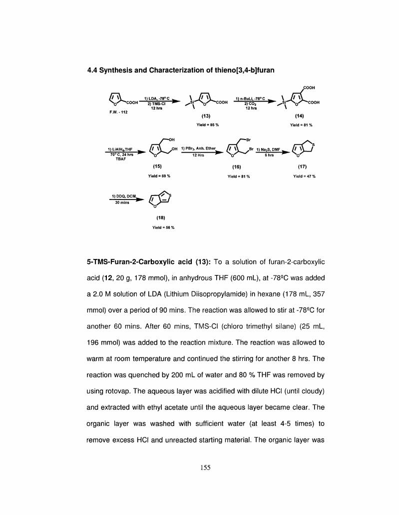
4.4 Synthesis and Characterization of thieno[3,4-b]furan
COOH
A \V 1)LDA,-78°C w \ / / \V 1)n-BuLi,-78°C ^ \ If \Y X 0 / ^ C O O H 2)TMS-CI ^ ^ S i ^ \ 0 / ^ C O O H 2) C02 • ^Si-^N 0^^COOH
12hrs \ 12hrs \ F.W.-112
(13) (14)
Yield = 85 % Yield = 81 %
r-C°" r-C* r-T^s 1)LiAIH4,THF ^ lfy-^S0H 1 ) P B r 3 , A n h E t h e ^ (fy^SBr D Na2S, DMF ^ AMA I 70°C,24hrs ^ N T * * * ^ i T i ^ ^ N r " * " ^ Sh^ ^ N C T ^
TBAF (15) (16) (17)
Yield = 69 % Yield = 81 % Yield = 47 %
1)DDQ,DCIVI ———^ 30 mins
(18)
Yield = 56 %
5-TMS-Furan-2-Carboxylic acid (13): To a solution of furan-2-carboxylic
acid (12, 20 g, 178 mmol), in anhydrous THF (600 mL), at -78QC was added
a 2.0 M solution of LDA (Lithium Diisopropylamide) in hexane (178 mL, 357
mmol) over a period of 90 mins. The reaction was allowed to stir at -78QC for
another 60 mins. After 60 mins, TMS-CI (chloro trimethyl silane) (25 mL,
196 mmol) was added to the reaction mixture. The reaction was allowed to
warm at room temperature and continued the stirring for another 8 hrs. The
reaction was quenched by 200 mL of water and 80 % THF was removed by
using rotovap. The aqueous layer was acidified with dilute HCI (until cloudy)
and extracted with ethyl acetate until the aqueous layer became clear. The
organic layer was washed with sufficient water (at least 4-5 times) to
remove excess HCI and unreacted starting material. The organic layer was
155
dried over MgS04 and concentrated to a crude dark brown solid 13 (28 g,
85% yield), confirmed by 1H-NMR, 13C-NMR and GC-MS.
Compound 13: 1H-NMR (500 MHz, DMSO-d6): 7.16 (1H, dd, J = 5.0 Hz),
6.87 (1H, dd , J = 5.0 Hz), 12.25 (2 H, br), 0.00 (9 H, s); 13C-NMR: 166.79,
161.13, 150.76, 123.28, 119.02, 107.64, 0.10; GC-MS (m/z): 184.
5-TMS- Furan-2-3-dicarboxylic acid (14): To a solution of 5-TMS-furan-2-
carboxylic acid (13, 20 g, 108 mmol), in anhydrous THF (600 ml_), at -78QC
was added a 2.5 M solution of n-BuLi in hexane (100 mL, 250 mmol) over a
period of 30 mins. The reaction was allowed to stir at -78QC for another 2
hrs at which time it was quenched with C02. It should be noted that upon
addition of CO2, the reaction became very thick and required some shaking
for efficient mixing. The reaction was allowed to warm at room temperature
and continued the stirring for 8 hrs. The reaction was quenched by 200 mL
of water and 80 % THF was removed by using rotovap. The aqueous, layer
was acidified with dilute HCI (until cloudy) and extracted with ethyl acetate
until the aqueous layer became clear. The organic layer was washed with
sufficient water (at least 4-5 times) to remove excess HCI. The organic layer
was dried over MgS04 and concentrated to a crude light brown solid 14 (20
g, 81% yield), confirmed by 1H-NMR, 13C-NMR and GC-MS.
Compound 14: 1H-NMR (500 MHz, DMSO-d6): 7.11 (1H, s, J = 5.1 Hz),
12.48 (2 H, br), 0.00 (9 H, s); 13C-NMR: 166.61, 165.60, 161.30, 151.01,
156
125.90, 124.23; GC-MS (m/z): 246.
2, 3-Bis(hydroxymethyl)furan (15): To a slurry of LiAIH4 (12.5 g, 329
mmol), in THF (400 mL) at 0QC, under an atmosphere of nitrogen, was
added 5-TMS-furan-2-3-dicarboxylic acid (14, 15 g, 65.8 mmol). The
reaction was allowed to warm to 70QC and was stirred for another 24 hrs.
After 24 hrs the reaction flask was kept in an ice bath and then 50 mL of
diethyl ether was added followed by the addition of 15 mL of water and 15
mL of 10 % NaOH solution. Addition of water was drop-wise. The organic
layer was dried over MgS04, filtered and the filtrate concentrated to a crude
solid, which was further dissolved in THF. The solution was then stirred for
10 mins and 1.0 M TBAF (5.4 mL, 18.1 mmol) in THF was added drop-wise
over a period of 15 mins. The mixture was stirred for another 6 hrs at 70QC.
Then 80% THF was removed by rotovap and acidified with dilute HCI (until
cloudy). The aqueous layer was extracted with ethyl acetate until the clear
aqueous layer is obtained. The organic layer was washed with plenty of
water (at least 4-5 times) to remove excess HCI and dried over MgS04 and
concentrated to a crude brown liquid 15 (5.8 g, 69 % yield), confirmed by
1H-NMR, 13C-NMR and GC-MS.
Compound 15 : 1H-NMR (500 MHz,CDCI3): 7.29 (1H, d, J = 5.0 Hz), 6.56
(1H, d , J = 5.0 Hz), 4.55 (2 H, s), 4.43 (2 H, s); 13C-NMR: 150.26, 141.45,
120.10, 110.97, 55.17, 54.73; GC-MS (m/z): 128.
157
2, 3-Bis(bromomethyl)furan (16): To a solution of 2, 3-
bis(hydroxymethyl)furan (15,10 g, 32 mmol) in anhydrous ether (300 mL) at
0QC, under a nitrogen atmosphere, was added PBr3 (4.5 mL, 48 mmol)
drop-wise over a period of 15 mins. The reaction was continued for another
6 hrs at room temperature and quenched by adding 50 mL of water. The
organic layer was extracted 4-5 times with water until the pH became
neutral. The organic layer was dried over MgS04, filtered and the filtrate
concentrated to a crude solid 16 (11.3 g, 81 % yield), confirmed by 1H-NMR,
13C-NMR and GC-MS.
Compound 16 : 1H-NMR (500 MHz,CDCI3): 7.38 (1H, d, J = 5.0 Hz), 6.42
(1H, d , J = 5.0 Hz), 4.55 (2 H, s), 4.36 (2 H, s); 13C-NMR: 148.10, 141.12,
115.14, 110.98, 23.17, 22.89; GC-MS (m/z): 254.
Dihydrothieno[3,4-b]furan (17): To a solution of sodium sulfide
nonahydrate (7.3 g, 30.4 mmol) in DMF (150 mL) at 30QC under a nitrogen
atmosphere, was added 2, 3bis (bromomethyl)thiophene (16, 10 g, 30.67
mmol) solution in DMF( 100 mL). 5-TMS-2,3Bis (bromomethyl)furan addition
was very slow and the temperature monitored to gradually increase from
30QC to 50QC. The reaction was continued for another 12 hrs at 50QC during
which time the contents became dark in color. The product was extracted in
diethyl ether (200 mL) and washed with sufficient water to remove DMF.
The organic layer was dried over MgSCU, filtered and the filtrate
concentrated to a crude dark brown liquid 17 (2.8 g, 40% yield). No
158
purification required.
Compound 17 :1H-NMR (500 MHz, CDCI3): 7.23 (1H, d), 6.12 (1H, d), 3.75
(4H, m); 13C-NMR (500 MHz, CDCI3): 155.0, 147.5, 124.6, 108.4, 28.5, 28.3.
GC-MS(m/z):126.
Thieno[3,4-6]furan (18): Dihydrothieno[3,4-t>]furan (17, 1.3 g , 10.3 tnmol)
and anhydrous methylene chloride (100 ml.) were taken in a dry 3-neck
flask, and cooled the solution to 0°C before adding DDQ (2.35 g, 10.3
mmol). The reaction mixture was stirred at 0°C for 30 minutes, and then
passed through the silica. After evaporating the solvent, the product was
purified by liquid chromatography using petroleum ether as an eluent. The
purified thieno[3,4-6]furan 18 was obtained (0.67 g, 50 % yield) confirmed
by 1H-NMR, 13C-NMR, GC-MS and FTIR.
Compound 18: 1H-NMR (500 MHz, CDCI3): 7.58 (1H, d), 6.92 (1H, d), 6.74
(1H, dd), 6.41 (1H, dd); 13C-NMR (500 MHz, CDCI3): 156.8, 153.0, 134.8,
107.1, 103.0, 94.9. GC-MS (m/ z): 124; FTIR (liquid film): 3131, 3063, 2949,
2925, 1715, 1541, 1434, 1421, 1323, 1273, 1203, 1114, 1103, 1002, 809,
767 cm"1.
4.5 Conclusion
159
In conclusion, we have demonstrated an efficient, inexpensive, and
versatile synthetic approach for preparing T34bT, 2-alkylated T34bT,
S34bT, and T34bF. These new routes open the door to a wide variety of
potential derivatives. We intend to more fully explore these substituents at
the 2-position using this chemistry, particularly with other electron-donating
groups. By using the same synthetic methodology, we also intend to make
different annelated heterocyclic systems with N and Te. The range of
practical applications of isomeric thienothiophene or thienofuran derivatives
and their 0-, N-, S-, Se-, Te- containing and fused analogues is vast,
ranging from prospects in the design of new medicines to the design of the
previously unknown liquid and clathrate crystals, charge-transfer
complexes, conducting polymers, nonlinear optical materials, and dyes,
among others.
160
4.6 References
1. (a) Aly, A. A.; Brown, A. B. Tetrahedron, 2009, 65(39), 8055-8089. (b) Sai
Sudhir, V.; Phani Kumar, N. Y.; Nasir Baig, R. B.; Chandrasekaran, S. J.
Org. Chem., 2009, 74(19), 7588-7591. (c) Sen, S.; Kulkami, P.; Borate, K.;
Pai, N. R. Tet. Lett, 2009, 50(28), 4128-4131. (d) Scalzullo, S. M.; Islam, R.
U.; Morgans, G. L; Michael, J. P.; van Otterlo, W. A. L. Tet. Lett., 2008,
49(52), 7403-7405. (e) Majumdar, K. C; Chakravorty, S.; De, N. Tet. Lett.,
2008, 49(21), 3419-3422. (f) Ozden Kasimogulla, B.; Cesur, Z. Turkish J. of
Chem., 2007, 31(6), 617-622.
2. (a) Liang, Y.; Feng, D.; Wu, Y.; Tsai, S.-T.; Li, G.; Ray, C; Yu, L. J. Am.
Chem. Soc, 2009, 131(22), 7792-7799. (b) Choudhury, K. R.; Lee, J.;
Chopra, N.; Gupta, A.; Jiang, X.; Amy, F.; So, F. Adv. Func. Mater.,
2009, 19(3), 491-496. (c) Liang, Y.; Feng, D.; Guo, J.; Szarko, J. M.; Ray,
C; Chen, L. X.; Yu, L. Macromolecules, 2009, 42(4), 1091-1098. (d) Liang,
Y.; Xiao, S.; Feng, D.; Yu, L. J. Phys. Chem. C, 2008, 112(21), 7866-7871.
3. Kumar, A.; Bokria, J. G.; Buyukmumcu, Z.; Dey, T.; Sotzing, G. A.
Macromolecules, 2008, 41(19), 7098-7108.
4. Cava, M. P.; Lakshmikantham, M. V. Comp. Heterocyclic Chem., 1984, 4,
1037.
5. Katz, T. J.; Rosenberger, M. J. Am. Chem. Soc, 1962, 84, 865.
6. Katz, T. J.; Rosenberger, M.; O'Hara, R. K. J. Am. Chem. Soc, 1964, 86,
249.
161
7. Milun, M.; Trinajstic, N.; Croat. Chem. Acta., 1977, 49, 107.
8. Gutman, I.; Milun, M.; Trinajstic, N. J. Am. Chem. Soc, 1977, 99, 1692.
9. Buemi, G.; J. Chim. Phys.-Chim.-biol., 1987, 84, 1147.
10. Litvinov, V. P.; Gol'dfarb, Y. L. Adv. Heterocyclic Chem., 1976, 19, 123.
11. (a) Wynberg, H.; Zwanenburg, D. J. Tet. Lett, 1967, 761. (b) Heffner, R.
J.; Joullie, M. M. Synth. Comm., 1991, 21(8-9), 1055-1069.
17. Moursounidis, J.; Wege, D. Tet. Lett., 1986, 27, 3045-8.
13. (a) Friedrichsen, W.; Schoning, A. Heterocycles, 1986, 24, 307. 14.
Schwendeman, I.; Hwang, J.; Welsh, D. M.; Tanner, D. B.; Reynolds, J. R.
Adv. Mater., 2001, 13, 634. (b) Schottland, P.; Zong, K.; Gaupp, C. L;
Thompson, B. C; Thomas, C. A.; Giurgiu, I.; Hickman, R.; Abboud, K. A.;
Reynolds, J. R. Macromolecules, 2000, 33, 7051. (c) Thompson, B. C;
Schottland, P.; Zong, K.; Reynolds, J. R. Chem. Mater., 2000, 12, 1563.
15. Yu, G.; Heeger, A. J. Synth. Met, 1997, 85, 1183.
16. (a) Brabec, C. J.; Sariciftci, N. S.; Hummelen, J. C. Adv. Func. Mater.,
2001, 11, 15. (b) Henckens, A.; Knipper, M.; Polec, I.; Manca, J.; Lutsen, L;
Vanderzande, D. Thin Solid Films, 2004, 451 & 572.
17. (a) Lee, B.; Seshadri, V.; Sotzing, G. A. Synth. Met, 2005, 152(1-3),
177-180. (b) Lee, B.; Seshadri, V.; Sotzing, G. A. Langmuir, 2005, 21(23),
10797-10802.
18. Invernale, M.A.; Seshadri, V.; Mamangun, D.M.D.; Ding, Y.; Filloramo,
F.; Sotzing, G.A. Chem. Mater., 2009, 21(14), 3332-3336.
19. Brandsma, L; Verkruijsse, H. D. Synth. Comm., 1990, 20, 2275.
162
20. (a) Lee, K.; Sotzing, G. A. Macromolecules, 2001, 34, 5746-5747. (b)
Sotzing, G. A.; Lee, K. Macromolecules, 2002, 35, 7281-7286.
21. (a) Pomerantz, M.; Gu, X. Synth. Met, 1997, 84, 243-244. (b)
Pomerantz, M.; Gu, X.; Zhang, S.X. Macromolecules, 2001, 34, 1817-1822.
22. Neef, C. J.; Brotherston, I. D.; Ferraris, J. P. Chem. Mater., 1999, 11,
1957-1958.
23. Yao, Y.; Liang, Y. Y.; Shrotriya, V.; Xiao, S. Q.; Yu, L. P.; Yang, Y. Adv.
Mater., 2007, 19, 3979-3983.
24. Buttery, J. H.; Moursounidis, J.; Wege, D. Aust. J. Chem., 1995, 48,
593-607.
25. Butte, W. A.; Case, F. H. J. Org. Chem., 1961, 26(11), 4690-4692.
26. Abdelmoty, S. G.; Heta, H. F. Bulletin of Pharm. Sci., Assiut Univ.,
2009, 32(1), 125-140.
27. Ha, S.-T.; Koh, T.-M.; Lin, H.-C; Yeap, G.-Y.; Win, Y.-F.; Ong, S.-T.;
Sivasothy, Y.; Ong, L.-K. Liquid Crystals, 2009, 36(9), 917-925.
28. Hasegawa, M.; Fujioka, A.; Kubo, T.; Honda, T.; Miyamoto, H.; Misaki,
Y. Chem. Lett, 2008, 37(4), 474-475.
29. Matsuo, Y.; Maruyama, M.; Gayathri, S. S.; Uchida, T.; Guldi, D. M.;
Kishida, H.; Nakamura, A.; Nakamura, E. J. Am. Chem. Soc,
2009, 131(35), 12643-12649.
30. (a)Baur, J.W.; Alexander, M.D. Jr.; Banach, M.; Denny, L.R.; Reinhardt,
B.A.; Vaia, R.A.; Fleitz, P.A.; Kirkpatrick, S.M. Chem. Mater.,
1999, 11(10), 2899-2906.(b) Klayman, D.L.; Griffin, S. T. J. Am. Chem.
Soc. 1972, 94, 197-200.
163

164
CHAPTER 5
LOW BAND GAP CONDUCTING POLYMER, POLY(SELONO[3,2-
c]THIOPHENE) and POLYSELENO[3,4-*>]THIOPHENE
5.1 Introduction
The field of conjugated polymers (CPs) has been growing at a remarkable pace
since the discovery of iodine doped polyacetylene as the conducting polymeric
material1 owing to their light weight, flexibility, low cost, and better processability
as compared to inorganic materials. CPs also offer large chemical structure
variation having wide range of electrical and optical properties resulting in their
application in the field of electrochromics,2 volatile organic gas sensors,3 non
linear optics,4 light-emitting diodes (LEDs),5 energy storage batteries,6 charge
dissipation film,7 protective coatings for corrosion prevention,8 to name a few.
The future perspective of CPs is in making cheap throw-away electronic devices
to advanced molecular electronic devices. The electrical and optical properties of
CPs are generally controlled by the energy gap between HOMO and LUMO of
the conjugated polymers.
There has been a great interest in low energy gap conjugated polymers for
their applications as an optically transparent electrode and hole-injection layer for
light emitting diodes.9 Low energy gap polymers are conjugated polymers having
energy gap equal or less than 1.5 eV.10They absorb > 600 nm in their neutral
state, and absorb in NIR region in their oxidized state making them optically
transparent in the visible region. The applications of low energy gap polymers
165
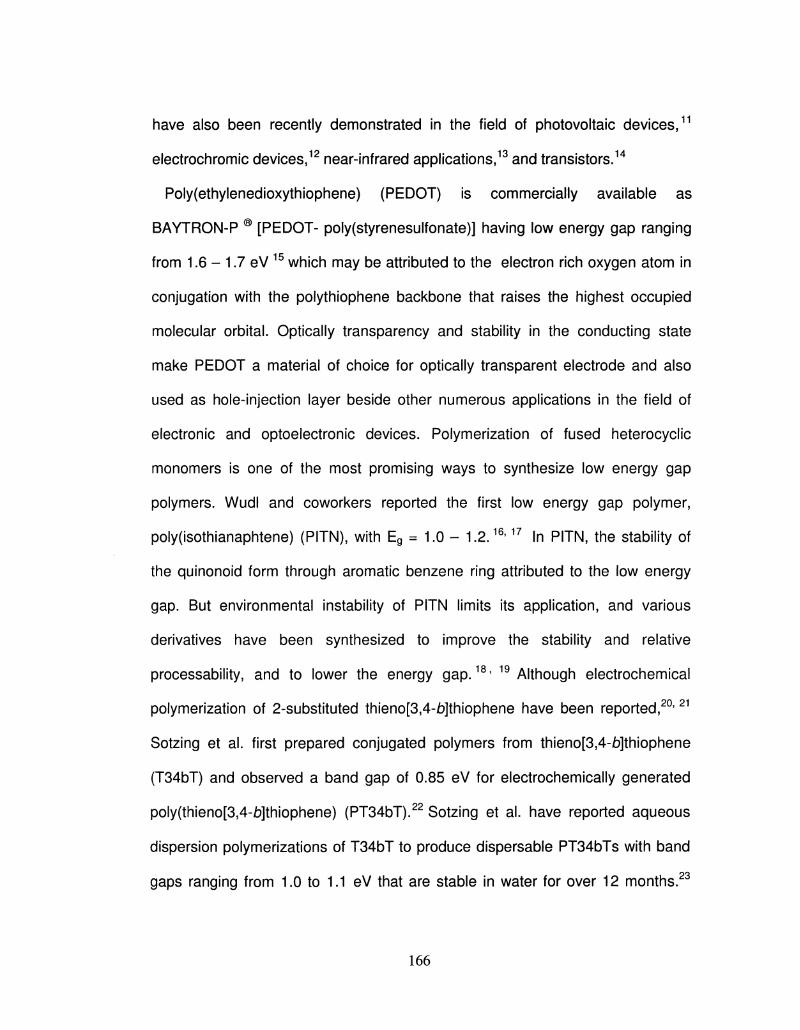
have also been recently demonstrated in the field of photovoltaic devices,11
electrochromic devices,12 near-infrared applications,13 and transistors.14
Poly(ethylenedioxythiophene) (PEDOT) is commercially available as
BAYTRON-P ® [PEDOT- poly(styrenesulfonate)] having low energy gap ranging
from 1.6 - 1.7 eV 15 which may be attributed to the electron rich oxygen atom in
conjugation with the polythiophene backbone that raises the highest occupied
molecular orbital. Optically transparency and stability in the conducting state
make PEDOT a material of choice for optically transparent electrode and also
used as hole-injection layer beside other numerous applications in the field of
electronic and optoelectronic devices. Polymerization of fused heterocyclic
monomers is one of the most promising ways to synthesize low energy gap
polymers. Wudl and coworkers reported the first low energy gap polymer,
poly(isothianaphtene) (PITN), with Eg = 1.0 - 1.2.16'17 In PITN, the stability of
the quinonoid form through aromatic benzene ring attributed to the low energy
gap. But environmental instability of PITN limits its application, and various
derivatives have been synthesized to improve the stability and relative
processability, and to lower the energy gap.18' 19 Although electrochemical
polymerization of 2-substituted thieno[3,4-jb]thiophene have been reported,20'21
Sotzing et al. first prepared conjugated polymers from thieno[3,4-b]thiophene
(T34bT) and observed a band gap of 0.85 eV for electrochemically generated
poly(thieno[3,4-jfc>]thiophene) (PT34bT).22 Sotzing et al. have reported aqueous
dispersion polymerizations of T34bT to produce dispersable PT34bTs with band
gaps ranging from 1.0 to 1.1 eV that are stable in water for over 12 months.23
166
Furthermore, we have demonstrated that insoluble PT34bT prepared via
oxidative chemical polymerization can be sulfonated to afford low band gap water
processable polymer, and they can be organized into thin films via layer-by-layer
deposition. 24 Sotzing et al. have reported that simultaneous
electropolymerization25 of T34bT and EDOT produce stable low band gap
conjugated copolymers. Sotzing et al. have reported also reported low band gap
polymer based on thieno[3,4-b]furan (T34bF) 26'27 for future photovoltaic
applications.
This chapter deals with the electrochemical synthesis and characterization of a
low energy gap polymer comprising seleno[3,2-c]thiophene (S32cT) seleno[3,4-
£>]thiophene (S34bT),26 a repeat unit bearing resemblance to both EDOS and
T34bT as shown in Figure 5.1. The polymer, S32cT, was found to have a very
low energy gap of 1.03 eV as calculated from the onset of absorption, and this
was in agreement with the theoretical value of 1.01 eV, wheseas the polymer
from S34bT has a band gap of 1.33 eV.
167
4 5 6
Figure 5.1 Chemical structures of ethylenedioxythiophene (1), thieno[334-£>]furan
(2), and thieno[3,4-fo]thiophene (3),ethylenedioxyselenophene (4), seleno[3,2-
c]thiophene (5), seleno[3,4-b]thiophene (6)
5.2 Seleno[3,2-c7thiophene and Seleno[3,4-b/thiophene Synthesis and
Characterization
Monomer Synthesis and Characterization. S32cT was synthesized according to
the reported procedure27 with modifications in the reaction conditions which are
necessary for the synthesis as shown in Scheme 5.1. The detailed systhesis of
S34bT (shown in Scheme 5.2) was discussed in the previous chapter 4.
Both S32cT and S34bT were characterized by using 1H-NMR, 13C-NMR, 77Se-
NMR and GC-MS, and results are in accordance with the reported values. 1H and
13C- NMR peaks positions were further confirmed by coupling between C atoms,
or C and H atoms via Heteronuclear Multiple Bond Correlation (HMBC) and
Heteronuclear Multiple- Quantum Coherence (HMQC) techniques.
168
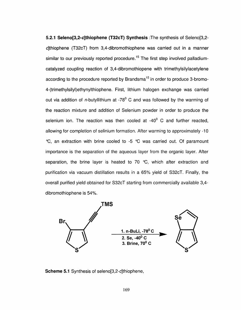
5.2.1 Seleno[3,2-c]thiophene (T32cT) Synthesis :The synthesis of Seleno[3,2-
c]thiophene (T32cT) from 3,4-dibromothiophene was carried out in a manner
similar to our previously reported procedure.15 The first step involved palladium-
catalyzed coupling reaction of 3,4-dibromothiopene with trimethylsilylacetylene
according to the procedure reported by Brandsma15 in order to produce 3-bromo-
4-(trimethylsilyl)ethynylthiophene. First, lithium halogen exchange was carried
out via addition of n-butyllithium at -78° C and was followed by the warming of
the reaction mixture and addition of Selenium powder in order to produce the
selenium ion. The reaction was then cooled at -40° C and further reacted,
allowing for completion of selinium formation. After warming to approximately -10
°C, an extraction with brine cooled to -5 °C was carried out. Of paramount
importance is the separation of the aqueous layer from the organic layer. After
separation, the brine layer is heated to 70 °C, which after extraction and
purification via vacuum distillation results in a 65% yield of S32cT. Finally, the
overall purified yield obtained for S32cT starting from commercially available 3,4-
dibromothiophene is 54%.
IMS
1.n-BuLi,-78°C 2. Se, -40° C 3. Brine, 70° C
Scheme 5.1 Synthesis of seleno[3,2-c]thiophene,
169
Procedure: All equipment was vacuum-dried and argon-purged before the
reaction. A 500 mL round-bottom, three-necked flask equipped with a
thermometer was charged with 300 mL of dry diethyl ether and 10 g (38.6 mmol)
of 3-bromo-4 (trimethylsilyl)ethynylthiophene while under argon. This solution
was maintained at a temperature of -78 °C and stirred for an another 15 min,
after which 16.8 mL of n-BuLi (2.5 M in hexanes, 42.4 mmol) was slowly added
dropwise via a syringe over a period of 60 min while keeping the temperature of
the solution around -78 °C. After addition, the solution was stirred for 2 h at - 78
°C, and then the solution was allowed to warm to ca. -45 °C, which took
approximately 1 h to achieve. The reaction mixture was allowed to stir for an
additional hour while maintaining a temperature of -45 °C. Selenium powder (3.2
g, 40.6 mmol) was then added slowly over a 10 min period to the flask via a
solids addition funnel, and the reaction mixture was allowed to warm to ca. -35
°C in order to fully dissolve the selenium. After approximately 10 min the initially
cloudy solution that resulted immediately after selenium addition had changed to
clear light yellow. The reaction mixture was then cooled to -45 °C, and stirring
was continued for an additional 2.5 h. Then the reaction mixture was slowly
warmed to -10 °C over a period of 30 min, and 250 mL of the reaction mixture
was then added to a 500mL separatory funnel equipped with a cooling jacket
containing a brine/ice mixture held at -5 °C. It should be noted that the separatory
funnel was first charged with 200 mL of brine, and then this solution was cooled
to -5 °C before the extraction. During the extraction the aqueous layer turned
cloudy light yellow after 30 s. It is pertinent at this stage to separate the layers.
170
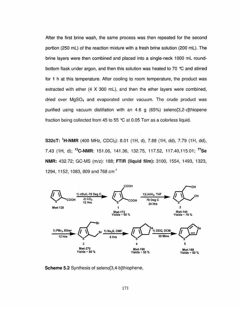
After the first brine wash, the same process was then repeated for the second
portion (250 mL) of the reaction mixture with a fresh brine solution (200 ml_). The
brine layers were then combined and placed into a single-neck 1000 mL round-
bottom flask under argon, and then this solution was heated to 70 °C and stirred
for 1 h at this temperature. After cooling to room temperature, the product was
extracted with ether (4 X 300 mL), and then the ether layers were combined,
dried over MgSCU and evaporated under vacuum. The crude product was
purified using vacuum distillation with an 4.6 g (65%) seleno[3,2-c]thiopene
fraction being collected from 45 to 55 °C at 0.05 Torr as a colorless liquid.
S32cT: 1H-NMR (400 MHz, CDCI3): 8.01 (1H, d), 7.88 (1H, dd), 7.79 (1H, dd),
7.43 (1H, d); 13C-NMR: 151.06, 141.36, 132.75, 117.52, 117.40,115.01; 77Se
NMR: 432.72; GC-MS (m/z): 188; FTIR (liquid film): 3100, 1554, 1493, 1323,
1294, 1152, 1083, 809 and 768 cm-1
Mwt-128
1)nBuli,-78 Peg C
COOH 2) c ° 2 12Hrs
COOH
COOH
Mwt-172 Yields - 50 %
y-*-Br
1)PBr3> Ether f T \ \ Br J !
12Hrs \ 0 / ^ ^
1)l_iAIH4>THF
70 Deg C 24Hrs
y^ -OH
Mwt-144 Yields - 70 %
Na2S, DMF^
6Hrs
// \\ / ^1P D Q D C M -Se
30 Mins
3 Mwt-270
Yields - 80 % Mwt-190
Yields ~ 50 %
cP Mwt-188
Yields ~ 50 %
Scheme 5.2 Synthesis of seleno[3,4-b]thiophene,
171
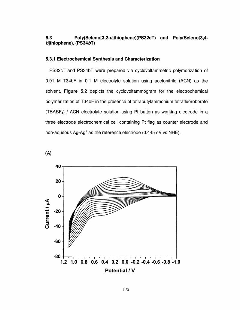
5-3 Poly(Seleno[3,2-c]thiophene)(PS32cT) and Poly(Seleno[3,4-6]thiophene), (PS346T)
5.3.1 Electrochemical Synthesis and Characterization
PS32cT and PS34bT were prepared via cyclovoltammetric polymerization of
0.01 M T34bF in 0.1 M electrolyte solution using acetonitrile (ACN) as the
solvent. Figure 5.2 depicts the cyclovoltammogram for the electrochemical
polymerization of T34bF in the presence of tetrabutylammonium tetrafluoroborate
(TBABF4) / ACN electrolyte solution using Pt button as working electrode in a
three electrode electrochemical cell containing Pt flag as counter electrode and
non-aqueous Ag-Ag+ as the reference electrode (0.445 eV vs NHE).
(A)
40 n ,
• 8 0 H 1 1 • 1 1 1 1 1 • 1 i 1 1 1 1 1 1 1 1 1 r
1.2 1.0 0.8 0.6 0.4 0.2 0.0 -0.2 -0.4 -0.6 -0.8 -1.0
Potential / V
172
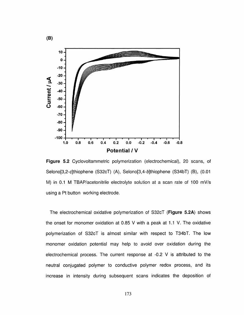
(B)
i • •*«
*-» c 0)
3
o
10-J
°1 -10 J
-20-]
-30 J
-40 J J
-50 J J
-60 -J
-70 J
-80 J
-90 J
-loo H — , — , — , — | — , — | — , — | — , — | — • — , — , — , — , — , — , — l 1.0 0.8 0.6 0.4 0.2 0.0 -0.2 -0.4 -0.6 -0.8
Potential/V
Figure 5.2 Cyclovoltammetric polymerization (electrochemical), 20 scans, of
Selono[3,2-c]thiophene (S32cT) (A), Selono[3,4-ib]thiophene (S34bT) (B), (0.01
M) in 0.1 M TBAP/acetonitrile electrolyte solution at a scan rate of 100 mV/s
using a Pt button working electrode.
The electrochemical oxidative polymerization of S32cT (Figure 5.2A) shows
the onset for monomer oxidation at 0.85 V with a peak at 1.1 V. The oxidative
polymerization of S32cT is almost similar with respect to T34bT. The low
monomer oxidation potential may help to avoid over oxidation during the
electrochemical process. The current response at -0.2 V is attributed to the
neutral conjugated polymer to conductive polymer redox process, and its
increase in intensity during subsequent scans indicates the deposition of
173
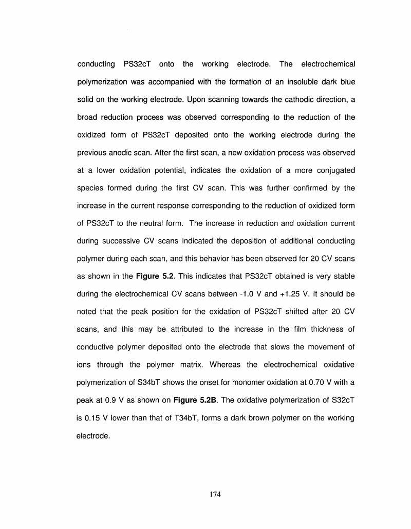
conducting PS32cT onto the working electrode. The electrochemical
polymerization was accompanied with the formation of an insoluble dark blue
solid on the working electrode. Upon scanning towards the cathodic direction, a
broad reduction process was observed corresponding to the reduction of the
oxidized form of PS32cT deposited onto the working electrode during the
previous anodic scan. After the first scan, a new oxidation process was observed
at a lower oxidation potential, indicates the oxidation of a more conjugated
species formed during the first CV scan. This was further confirmed by the
increase in the current response corresponding to the reduction of oxidized form
of PS32cT to the neutral form. The increase in reduction and oxidation current
during successive CV scans indicated the deposition of additional conducting
polymer during each scan, and this behavior has been observed for 20 CV scans
as shown in the Figure 5.2. This indicates that PS32cT obtained is very stable
during the electrochemical CV scans between -1.0 V and +1.25 V. It should be
noted that the peak position for the oxidation of PS32cT shifted after 20 CV
scans, and this may be attributed to the increase in the film thickness of
conductive polymer deposited onto the electrode that slows the movement of
ions through the polymer matrix. Whereas the electrochemical oxidative
polymerization of S34bT shows the onset for monomer oxidation at 0.70 V with a
peak at 0.9 V as shown on Figure 5.2B. The oxidative polymerization of S32cT
is 0.15 V lower than that of T34bT, forms a dark brown polymer on the working
electrode.
174
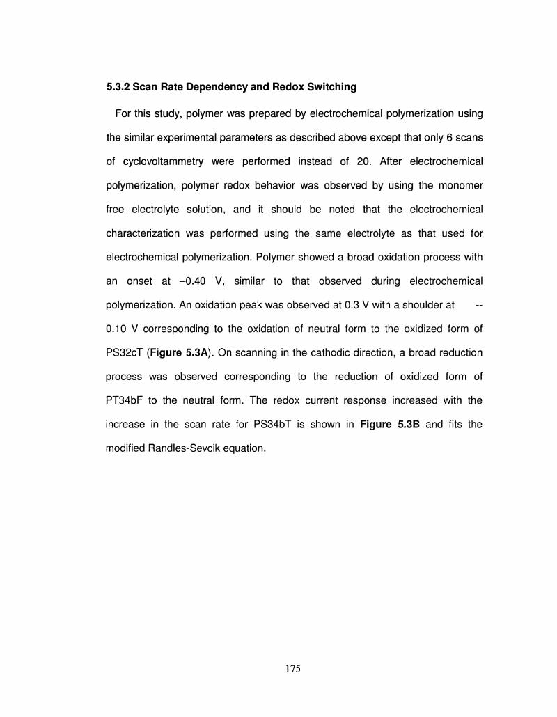
5.3.2 Scan Rate Dependency and Redox Switching
For this study, polymer was prepared by electrochemical polymerization using
the similar experimental parameters as described above except that only 6 scans
of cyclovoltammetry were performed instead of 20. After electrochemical
polymerization, polymer redox behavior was observed by using the monomer
free electrolyte solution, and it should be noted that the electrochemical
characterization was performed using the same electrolyte as that used for
electrochemical polymerization. Polymer showed a broad oxidation process with
an onset at -0.40 V, similar to that observed during electrochemical
polymerization. An oxidation peak was observed at 0.3 V with a shoulder at
0.10 V corresponding to the oxidation of neutral form to the oxidized form of
PS32cT (Figure 5.3A). On scanning in the cathodic direction, a broad reduction
process was observed corresponding to the reduction of oxidized form of
PT34bF to the neutral form. The redox current response increased with the
increase in the scan rate for PS34bT is shown in Figure 5.3B and fits the
modified Randles-Sevcik equation.
175
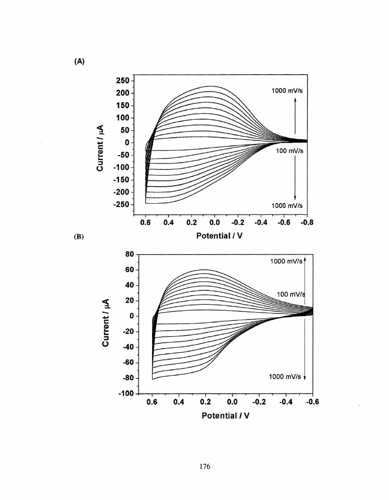
(A)
(B)
8>
o
1000 mV/s
100mV/s
1000 mV/s
0.6 0.4 0.2 0.0 -0.2
Potential / V
-0.4 -0.6 -0.8
c <D
o
80
60 -I
40 J
20 J
0
-20
-40 H
-60
-80-|
-100
1000 mV/s
100mV/d
1000 mV/s
0.6 0.4 0.2 0.0 -0.2 -0.4 -0.6
Potential / V
176
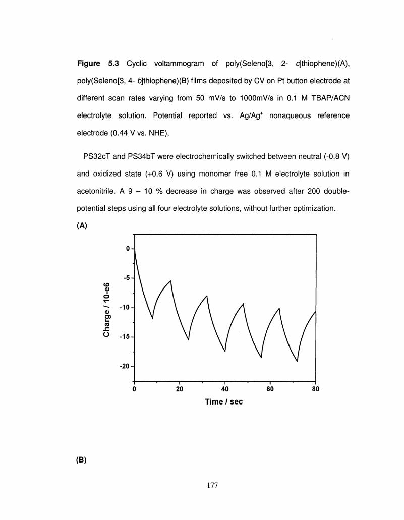
Figure 5.3 Cyclic voltammogram of poly(Seleno[3, 2- c]thiophene)(A),
poly(Seleno[3, 4- b]thiophene)(B) films deposited by CV on Pt button electrode at
different scan rates varying from 50 mV/s to 1000mV/s in 0.1 M TBAP/ACN
electrolyte solution. Potential reported vs. Ag/Ag+ nonaqueous reference
electrode (0.44 V vs. NHE).
PS32cT and PS34bT were electrochemically switched between neutral (-0.8 V)
and oxidized state (+0.6 V) using monomer free 0.1 M electrolyte solution in
acetonitrile. A 9 - 10 % decrease in charge was observed after 200 double-
potential steps using all four electrolyte solutions, without further optimization.
(A)
CD <D i
O T -
<D O) i . (S -C O
0 20 40 60 80
Time / sec
(B)
177
-10 A
-15J
-20 A
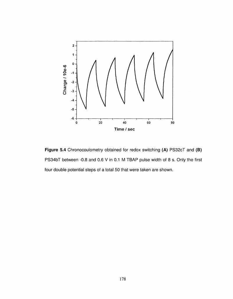
Time / sec
Figure 5.4 Chronocoulometry obtained for redox switching (A) PS32cT and (B)
PS34bT between -0.8 and 0.6 V in 0.1 M TBAP pulse width of 8 s. Only the first
four double potential steps of a total 50 that were taken are shown.
178
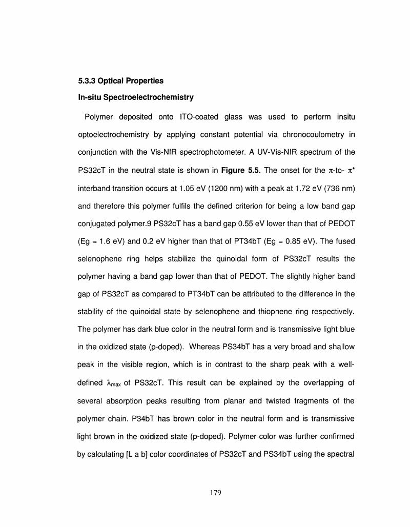
5.3.3 Optical Properties
In-situ Spectroelectrochemistry
Polymer deposited onto ITO-coated glass was used to perform insitu
optoelectrochemistry by applying constant potential via chronocoulometry in
conjunction with the Vis-NIR spectrophotometer. A UV-Vis-NIR spectrum of the
PS32cT in the neutral state is shown in Figure 5.5. The onset for the 7u-to- 71*
interband transition occurs at 1.05 eV (1200 nm) with a peak at 1.72 eV (736 nm)
and therefore this polymer fulfils the defined criterion for being a low band gap
conjugated polymer.9 PS32cT has a band gap 0.55 eV lower than that of PEDOT
(Eg = 1.6 eV) and 0.2 eV higher than that of PT34bT (Eg = 0.85 eV). The fused
selenophene ring helps stabilize the quinoidal form of PS32cT results the
polymer having a band gap lower than that of PEDOT. The slightly higher band
gap of PS32cT as compared to PT34bT can be attributed to the difference in the
stability of the quinoidal state by selenophene and thiophene ring respectively.
The polymer has dark blue color in the neutral form and is transmissive light blue
in the oxidized state (p-doped). Whereas PS34bT has a very broad and shallow
peak in the visible region, which is in contrast to the sharp peak with a well-
defined A,max of PS32cT. This result can be explained by the overlapping of
several absorption peaks resulting from planar and twisted fragments of the
polymer chain. P34bT has brown color in the neutral form and is transmissive
light brown in the oxidized state (p-doped). Polymer color was further confirmed
by calculating [L a b] color coordinates of PS32cT and PS34bT using the spectral
179
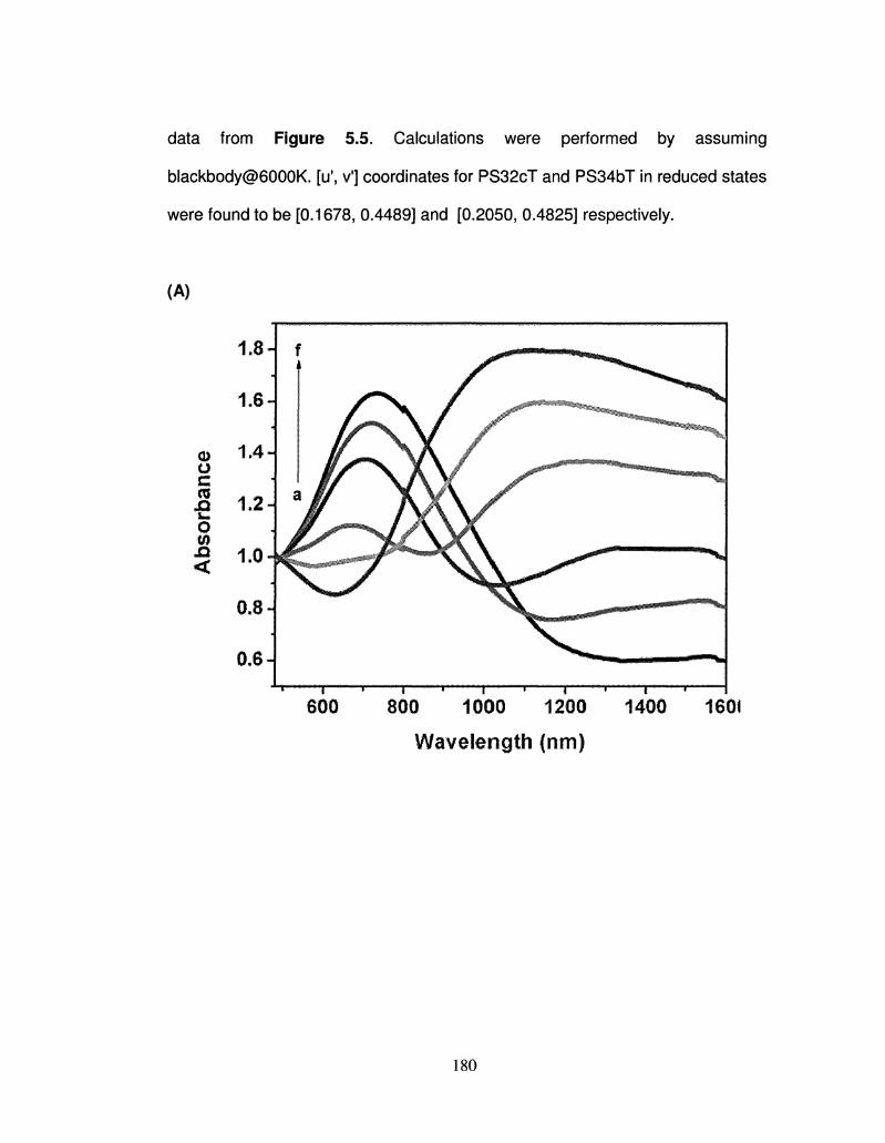
data from Figure 5.5. Calculations were performed by assuming
blackbody@6000K. [u\ v'] coordinates for PS32cT and PS34bT in reduced states
were found to be [0.1678, 0.4489] and [0.2050, 0.4825] respectively.
(A)
0)
o m •O o m n <
0.6 A
600 800 1000 1200 1400
Wavelength (nm)
1601
180
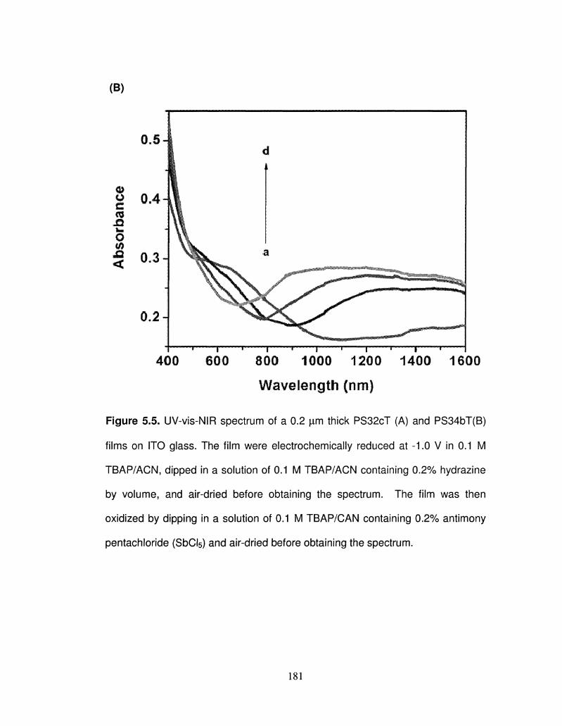
(B)
' 1 « 1 « 1 ' 1 ' 1 «•
400 600 800 1000 1200 1400 1600
Wavelength (nm)
Figure 5.5. UV-vis-NIR spectrum of a 0.2 |xm thick PS32cT (A) and PS34bT(B)
films on ITO glass. The film were electrochemically reduced at -1.0 V in 0.1 M
TBAP/ACN, dipped in a solution of 0.1 M TBAP/ACN containing 0.2% hydrazine
by volume, and air-dried before obtaining the spectrum. The film was then
oxidized by dipping in a solution of 0.1 M TBAP/CAN containing 0.2% antimony
pentachloride (SbCI5) and air-dried before obtaining the spectrum.
181
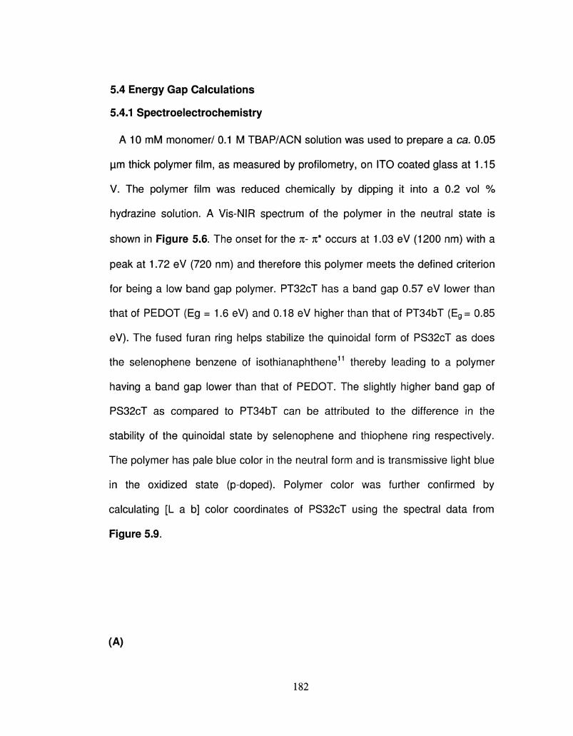
5.4 Energy Gap Calculations
5.4.1 Spectroelectrochemistry
A 10 mM monomer/ 0.1 M TBAP/ACN solution was used to prepare a ca. 0.05
|jm thick polymer film, as measured by profilometry, on ITO coated glass at 1.15
V. The polymer film was reduced chemically by dipping it into a 0.2 vol %
hydrazine solution. A Vis-NIR spectrum of the polymer in the neutral state is
shown in Figure 5.6. The onset for the n- n* occurs at 1.03 eV (1200 nm) with a
peak at 1.72 eV (720 nm) and therefore this polymer meets the defined criterion
for being a low band gap polymer. PT32cT has a band gap 0.57 eV lower than
that of PEDOT (Eg = 1.6 eV) and 0.18 eV higher than that of PT34bT (Eg= 0.85
eV). The fused furan ring helps stabilize the quinoidal form of PS32cT as does
the selenophene benzene of isothianaphthene11 thereby leading to a polymer
having a band gap lower than that of PEDOT. The slightly higher band gap of
PS32cT as compared to PT34bT can be attributed to the difference in the
stability of the quinoidal state by selenophene and thiophene ring respectively.
The polymer has pale blue color in the neutral form and is transmissive light blue
in the oxidized state (p-doped). Polymer color was further confirmed by
calculating [L a b] color coordinates of PS32cT using the spectral data from
Figure 5.9.
(A)
182
CD O c CO L .
o W n <
1.8-
1.6-
1.4-
1.2-J
1.0-1
0.8 J J
0.6 J
J^SL / Oxidized ^
^ ^ Reduced
Li 1 1 1 1 1 1 1 1 1 1 1
600 800 1000 1200
Wavelength (nm)
1400 1600
(B)
183
0.5 -'
o 0.4-<o n o to
0.2 J
400 600 800 1000 1200 1400 1600
Wavelength (nm)
Figure 5.6 Vis-NIR spectrum of a 0.05 jim thick poly(thieno[3,4-b]furan) film on
ITO glass. The film was chemically reduced using 0.2 % v/v hydrazine solution in
acetonitrile, and oxidized using 0.2% v/v antimony (V) chloride solution in
acetonitrile.
5.4.2 Cyclic Voltametry (p and n doping):
Cyclic voltammetry (CV) was used to measure oxidation and reduction
potentials. PS32cT presents one reversible p-doping [Eox= - 0.22 V vs. Ag/Ag+
and -0.26 V ferrocene / ferrocenium (Fc/Fc+)] and one irreversible n-doping
(Ered= - 1 -25V vs Ag/Ag+ and - 1.29 V vs Fc/Fc+) process (Figure 5.7A.The
HOMO ( - 4.54 eV) and LUMO (-3.51 eV) of PS32cT could be calculated from
these electrochemical results. Bang Gap = 1.03 eV. Whereas PS34bT presents
184
one reversible p-doping [Eox= 0.55 V vs Ag/Ag+ and 0.51 V vs ferrocene /
ferrocenium (Fc/Fc+)] and one irreversible n-doping (Ereci= - 0.95 V vs Ag/Ag+
and -0.99 V vs Fc/Fc+) process (Figure 5.7B). The HOMO (- 5.31 eV) and
LUMO (-3.81 eV) were calculated base on CV, shown in Figure 5.7B
(A)
(B)
0.0 -0.5 -1.0
Potential (V) 0.0 -0.5 -1.0
Potentia/V -1.5 -2.0
Figure 5.7 1st and 2nd scan of p- and n-doping cyclic voltammetry for (A)
poly(S32cT) and (B) poly(S34bT) on a Pt button working electrode at a scan rate
of 100 mV/s in 0.1 M TBAP/acetonitrile showing the first scan (I) and the second
scan (II).
185
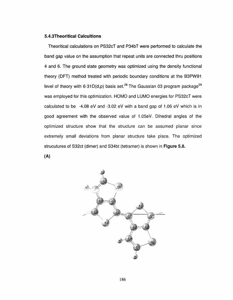
5.4.3Theoritical Calcultions
Theoritical calculations on PS32cT and P34bT were performed to calculate the
band gap value on the assumption that repeat units are connected thru positions
4 and 6. The ground state geometry was optimized using the density functional
theory (DFT) method treated with periodic boundary conditions at the B3PW91
level of theory with 6-31D(d,p) basis set.28 The Gaussian 03 program package29
was employed for this optimization. HOMO and LUMO energies for PS32cT were
calculated to be -4.08 eV and -3.02 eV with a band gap of 1.06 eV which is in
good agreement with the observed value of 1.05eV. Dihedral angles of the
optimized structure show that the structure can be assumed planar since
extremely small deviations from planar structure take place. The optimized
strucutures of S32ct (dimer) and S34bt (tetramer) is shown in Figure 5.8.
(A)
186
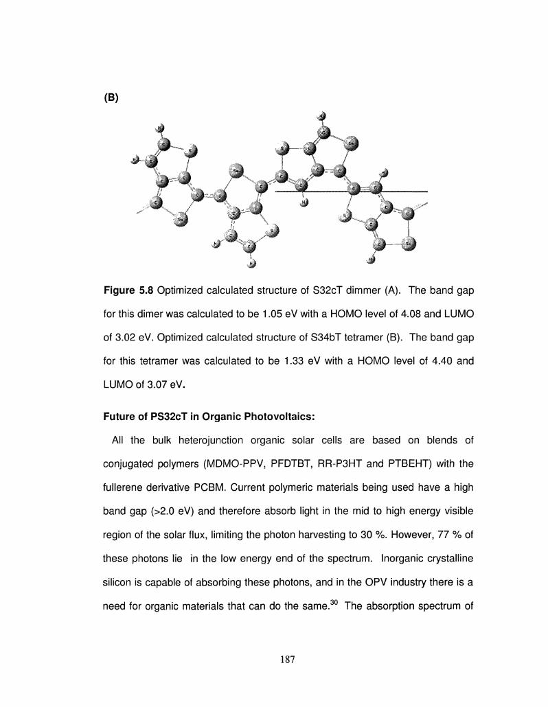
Figure 5.8 Optimized calculated structure of S32cT dimmer (A). The band gap
for this dimer was calculated to be 1.05 eV with a HOMO level of 4.08 and LUMO
of 3.02 eV. Optimized calculated structure of S34bT tetramer (B). The band gap
for this tetramer was calculated to be 1.33 eV with a HOMO level of 4.40 and
LUMO of 3.07 eV.
Future of PS32cT in Organic Photovoltaics:
All the bulk heterojunction organic solar cells are based on blends of
conjugated polymers (MDMO-PPV, PFDTBT, RR-P3HT and PTBEHT) with the
fullerene derivative PCBM. Current polymeric materials being used have a high
band gap (>2.0 eV) and therefore absorb light in the mid to high energy visible
region of the solar flux, limiting the photon harvesting to 30 %. However, 77 % of
these photons lie in the low energy end of the spectrum. Inorganic crystalline
silicon is capable of absorbing these photons, and in the OPV industry there is a
need for organic materials that can do the same.30 The absorption spectrum of
187
PS32cT in its neutral state is shown in Figure 5-9, and for comparison is overlaid
with spectra of P3HT, MEH-PPV, PT34bT along with the solar flux under air
mass 1.5 conditions and absorption of crystalline silicon.31 Figure 5.9 shows the
solar spectrum under Air Mass 1.5 conditions (AM1.5-G; i.e. sun light that passes
through the atmosphere at 42Q from horizon) along with overlaid spectra for the
light trapped (absorbed) by currently employed light harvesting materials:
crystalline silicon, P3HT, MEH-PPV, and that of PT34bT, and PT34bF. The Y-
axis of Figure 5.9 is in energy units (W/m2 nm) corresponding to solar flux, and
the absorption spectra of the organic materials were normalized to an arbitrary
height but the A,max of the materials was not altered. Thus, the Y-axis of the
materials should be in normalized dimensionless absorbance scale. However,
the figure is accurate in terms of the wavelength, i.e. abscissa, which means that
the new materials show a remarkable matching to that of the silicon spectrum. It
is clear that crystalline silicon has a broad absorption, and the currently used
organic polymers suffer both in terms of absorption range and the location of the
maximum: they have relatively sharp absorptions at the high energy end.
However, PS32cT exhibits broader absorptions and at lower energies - where
maximum number of photons are. The absorption spectra of PS32cT match well
with that of crystalline silicon and therefore have the ability to trap photons across
the spectrum, including the low energy end. This is a direct result of the low
band gap of these unique materials, and thus are a good match, in terms of
absorption characteristics, with the projected need for low band gap materials.
The potential to use both PS32cT and P3HT (or other higher band gap
188
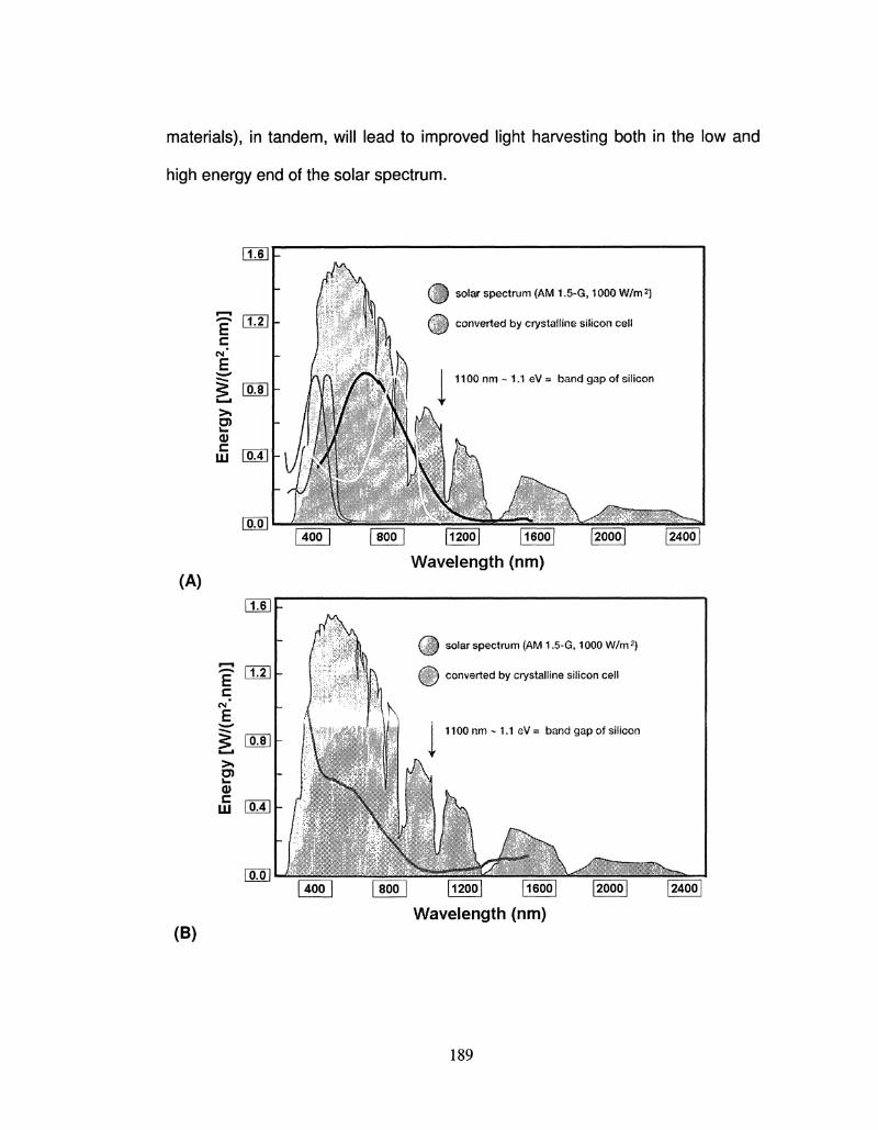
materials), in tandem, will lead to improved light harvesting both in the low and
high energy end of the solar spectrum.
c CM"
E
(A)
fool L i
Q solar spectrum (AM 1.5-G, 1000 W/m2)
Cj converted by crystalline silicon ceil
1100 nm - 1.1 eV = band gap of silicon
2400
Wavelength (nm)
(/^ solar spectrum (AM 1.5-G, 1000 W/m2
£ j ) converted by crystalline silicon cell
1100 nm - 1.1 eV ~ band gap of silicon
24001
(B) Wavelength (nm)
189
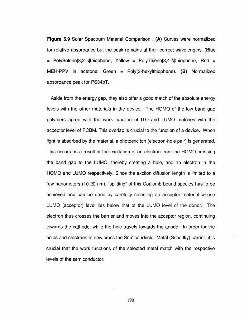
Figure 5-9 Solar Spectrum Material Comparison . (A) Curves were normalized
for relative absorbance but the peak remains at their correct wavelengths. (Blue
= PolySeleno[3,2-c]thiophene, Yellow = PolyThieno[3,4-b]thiophene, Red =
MEH-PPV in acetone, Green = Poly(3-hexylthiophene). (B) Normalized
absorbance peak for PS34bT.
Aside from the energy gap, they also offer a good match of the absolute energy
levels with the other materials in the device. The HOMO of the low band gap
polymers agree with the work function of ITO and LUMO matches with the
acceptor level of PCBM. This overlap is crucial to the function of a device. When
light is absorbed by the material, a photoexciton (electron-hole pair) is generated.
This occurs as a result of the excitation of an electron from the HOMO crossing
the band gap to the LUMO, thereby creating a hole, and an electron in the
HOMO and LUMO respectively. Since the exciton diffusion length is limited to a
few nanometers (10-20 nm), "splitting" of this Coulomb bound species has to be
achieved and can be done by carefully selecting an acceptor material whose
LUMO (acceptor) level lies below that of the LUMO level of the donor. The
electron thus crosses the barrier and moves into the acceptor region, continuing
towards the cathode, while the hole travels towards the anode. In order for the
holes and electrons to now cross the Semiconductor-Metal (Schottky) barrier, it is
crucial that the work functions of the selected metal match with the respective
levels of the semiconductor.
190
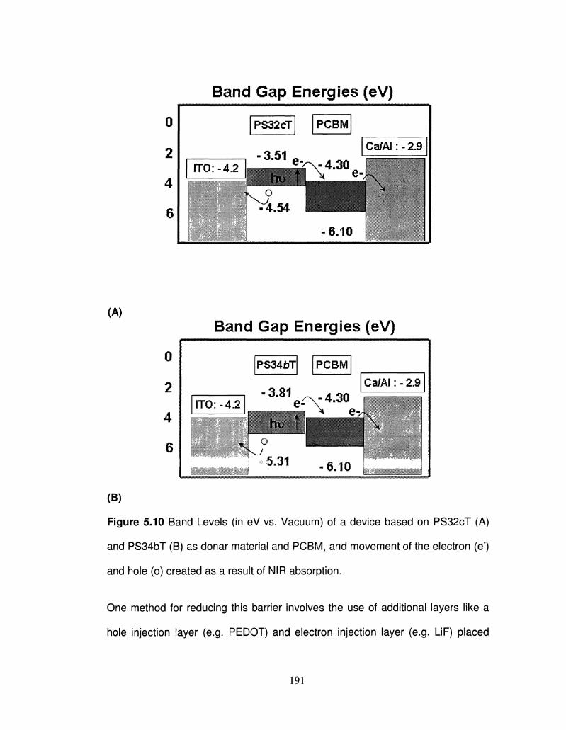
Band Gap Energies (eV)
0
2
4
6
ITO:-4.2
(A)
0
2
4
6
Band Gap Energies (eV)
PS34bT PCBM
Ca/AI: - 2.9
ITO:-4.2
L.„.^.
(B)
Figure 5.10 Band Levels (in eV vs. Vacuum) of a device based on PS32cT (A)
and PS34bT (B) as donar material and PCBM, and movement of the electron (e)
and hole (o) created as a result of NIR absorption.
One method for reducing this barrier involves the use of additional layers like a
hole injection layer (e.g. PEDOT) and electron injection layer (e.g. LiF) placed
191
between the metal electrode and the semiconductor. In order to avoid this extra
level of construction, the design of an OPV device must include a careful
selection of materials with appropriate band levels. Figure 5-10 shows the band
levels of PS32cT and PS34bT as a donar material and PCBM along with the
work functions of ITO32"33 and Calcium/Aluminum. The HOMO level of PS32cT
was calculated from cyclic voltammogram (CV) measurements vs. ferrocene,33'36
and since the band gap is known, the LUMO level found. As explained earlier,
exciton formation will occur in the PT34bF layer after NIR absorption, and the
electron will move from the LUMO of PS32cT (-3.65 eV) into the acceptor level of
PCBM (-3.75 eV) and since the work function of cathode is -4.3 eV, will flow into
the Aluminum electrode. The hole generated in the HOMO of PS32cT (-4.58
eV), on the other hand, will move into the ITO anode having a work function of -
4.2 eV.
5.5 Conductivity
A 1.2 cm diameter pellet obtained from electrochemically polymerized PS32cT
and PS34bT were used for conductivity measurements. Five measurements of
each polymer were taken for each experiment by varying the applied current
between 1 x 10"5 and 1 x 10~7 A, and the resistance values are same at these
different current within 1- 2% error indicating the ohmic behavior. In neutral form,
both PS32cT and PS34bT showed a conductivity of ~10"5 S/ cm. After exposing
the pellet to iodine vapors for 30 min., the conductivity increased to ~10"2 S/cm.
192
5.6 Conclusions
This chapter includes a modified procedure for the synthesis of S32cT and
S34bT monomer with an emphasis to avoid purification procedure until the last
synthesis step. The lower oxidation potential of S32cT and S34bT helps in
avoiding overoxidation of polymer during electrochemical polymerization. S32cT
and S34bT showed stable redox behavior with broad oxidation and reduction
processes observed during cyclic voltammetric scans. PS32cT showed a A,max at
720 nm and an Eg of 1.04 eV which qualifies it as a low energy gap polymer. This
value is similar to that of 1.03 eV for chemically neutralized PS32cT. There is a
increase in the transmittance in the visible region on going from -0.6 to +0.6 V
indicating completely oxidized and reduced states at +0.6 V and -0.6 V,
respectively.
193
5.7 References
1. (a) Chiang, C. K.; Fincher, C. R., Jr.; Park, Y. W.; Heeger, A. J.; Shirakawa,
H.; Louis, E. J.; Gau, S. C; MacDiarmid, A. G. Phys. Rev. Lett. 1977, 39, 1098.
(b) Shirakawa, H.; Louis, E. J.; MacDiarmid, A. G.; Chiang, C. K.; Heeger, A. J. J.
Chem. Soc, Chem. Commun. 1977, 578.
2. (a) Schwendeman, I.; Hwang, J.; Welsh, D. M.; Tanner, D. B.; Reynolds, J. R.
Adv. Mater. 2001, 13, 634. (b) Schottland, P.; Zong, K.; Gaupp, C. L; Thompson,
B. C; Thomas, C. A.; Giurgiu, I.; Hickman, R.; Abboud, K. A.; Reynolds, J. R.
Macromolecules 2000, 33, 7051. (c) Thompson, B. C; Schottland, P.; Zong, K.;
Reynolds, J. R. Chem. Mater. 2000, 12, 1563.
3. (a) McQuade, D. T.; Pullen, A. E.; Swager, T. M. Chem. Rev. 2000, 100, 2537.
(b) Yang, J.-S.; Swager, T. M. J. Am. Chem. Soc. 1998, 120, 11864. (c) Sotzing,
G. A.; Briglin, S.; Grubbs, R. H.; Lewis, N. S. Anal. Chem. 2000, 72, 3181.
4. Ma, H.; Chen, B.; Sassa, T.; Dalton, L. R.; Jen, A. K.-Y. J. Am. Chem. Soc.
2001, 723,986-987.
5. Yu, G.; Heeger, A. J. Synth. Met. 1997, 85, 1183.
6. Ferraris, J. P.; Eissa, M. M.; Brotherston, I. D.; Loveday, D. C. Chem. Mater.
1998, 17,3528-3535.
7. Jonas, F.; Heywang, G. Electrochim. Acta 1994, 39, 1345.
8. Perucki, M.; Chandrasekhar, P. Synth. Met. 2001, 119, 385-386.
9. (a) Gross, M.; Muller, D. C; Nothofer, H.-G.; Scherf, U.; Neher, D.; Brauchle,
C; Merrholz, K. Nature (London) 2000, 405, 661-665. (b) Book, K.; Ba'ssler, H.;
Elschner, A.; Kirchmeyer, S. Org. Electron.2003, 4, 227-232.
194
10. Pomerantz, M. In Handbook of Conducting Polymers, 2nd ed.; Skotheim, A.,
Elsenbaumer, R., Reynolds, J.; Marcel Dekker Inc.: New York, 1998; p 277.
11.(a) Brabec, C. J.; Sariciftci, N. S.; Hummelen, J. C. Adv. Func. Mater. 2001,
11. 15. (b) Henckens, A.; Knipper, M.; Polec, I.; Manca, J.; Lutsen, L;
Vanderzande, D. Thin Solid Films 2004, 451 & 572.
12. (a) I. Schwendeman; J. Hwang; D. M. Welsh; D. B. Tanner; J. R. Reynolds
Adv. Mater. 2001, 13, 634. (b) Sonmez, G.; Sonmez, H. B.; Shen C. K. F.; Wudl,
F. Adv. Mater. 2004, 16, 1905. (c) Argun, A. A.; Aubert, P.-H.; Thompson, B. C;
Schwendeman, I.; Gaupp, C. L; Hwang, J.; Pinto, N. J.; Tanner, D. B.;
MacDiarmid, A. G.; Reynolds, J. R. Chem. Mater. 2004, 16, 4401.
13. (a) Sonmez, G.; Meng, H.; Wudl, F. Chem. Mater. 2003, 15, 4923. (b) Meng,
H.; Tucker, D.; Chaffins, S.; Chen, Y.; Helgeson, R.; Dunn, B.; Wudl, F. Adv.
Mater. 2003, 15, 146. (c) P. Chandrasekhar, P.; Birur, G. C; Stevens, P.; Rawel,
S.; Pierson, E. A.; Miller, K., L Synth. Met. 2001, 119, 293.
14. (a) Chen, M. X.; Perzon, E.; Robisson, N.; Joensson, S. K. M.; Andersson,
M. R.; Fahlman, M.; Berggren, M. Synth. Met. 2004, 146, 233. (b) Brabec, C. J.;
Winder, C; Sariciftci, N. S.; Hummelen, J. C; Dhanabalan, A.; Van H., Paul A.;
Janssen, R. A. J. Adv. Func. Mater. 2002, 12, 709.
15. Kiebooms, R. H. L; Goto, H.; Akagi, K. Macromolecules 2001, 34, 7989.
16. Wudl, F.; Kobayashi, M.; Heeger, A. J. J. Org. Chem. 1984, 49, 3382.
17. (a) Kobayashi, M.; Colaneri, N.; Boysel, M.; Wudl, F.; Heeger, A. J. J. Chem.
Phys. 1985, 82, 5717. (b) Colerneri, N.; Kobayashi, M.; Heeger, A. J.; Wudl, F.
Synth. Met. 1986, 14,45.
195
18. (a) van Asselt, R.; Vanderzande, D.; Gelan, J.; Froehling, P. E.; Aagaard, O.
Synth. Met. 2000, 110, 25. (b) Kisselev, R.; Thelakkat, M. Macromolecules 2004,
37, 8951. (c) Goris, L; Loi, M. A.; Cravino, A.; Neugebauer, H.; Sariciftci, N. S.;
Polec, I.; Lutsen, L; Andries, E.; Manca, J.; De Schepper, L; Vanderzande, D.
Synth. Met. 2003, 138, 249.
19. (a) Meng, H.; Wudl, F. Macromolecules 2001, 34, 1810. (b) Cravino, A.; Loi,
M. A.; Scharber, M. C; Winder, C; Neugebauer, H.; Denk, P.; Meng, H.; Chen,
Y.; Wudl, F.; Sariciftci, N. S. Synth. Met. 2003, 137, 1435.
20. Pomerantz, M.; Gu, X.; Zhang, S. X. Macromolecules 2001, 34,1817.
21. Neef, C. J.; Brotherston, I. D.; Ferraris, J. P. Chem. Mater. 1999, 11, 1957.
22. (a) Lee, K.; Sotzing, G.A. Macromolecules 2001, 34, 5746. (b) Lee, K.;
Sotzing, G.A. Macromolecules 2002, 35, 7281.
23. Lee, B.; Seshadri, V.; Sotzing, G. A.; Langmuir2005, 21, 10797.
24. Lee, B.; Seshadri, V.; Sotzing, G. A. Adv. Mater. 2005, 17, 1792.
25. Seshadri, V.; Lu, W.; Sotzing, G. A. Langmuir2003, 19, 9479.
26. Kumar, A.; Buyukmumcu, Z.; Sotzing, G.A. Macromolecules 2006, 39, 2723.
27. Moursounidis, J.; Wege, D. Tetrahedron Lett. 1986, 27, 3045.
28. Tsai, F.-C; Chang, C.-C; Liu, C.-L; Chen, W.-C; Jenekhe, S. A.
Macromolecules 2005, 38, 1958.
29. Frisch, M. J. et al.; Gaussian 03, Revision C.02, Gaussian, Inc., Wallingford
CT, 2004.
196
30. Lewis, N. S. Basic Energy Needs for Solar Energy Utilization:Report of the
Basic Energy Sciences Workshop on Solar Energy Utilization. US Department of
Energy, Office of Basic Energy Science, Washington, DC; April 18-21, 2005.
31. Internet:
http://www.vicphysics.org/documents/events/stav2005/spectrum.JPG (accessed
Nov. 12, 2007).
32. Sugiyama, K.; Ishii, H.; Ouchi, Y.; Seki, K. J. Appl. Phys. 2000, 87, 295.
33. Andreasson, M.; Tengelin-Nilsson, M.; Andersson, T. G.; liver, L; Kanski, J.
Org. Electron. 2005, 6, 175.
34 Khan, T.; Mcdouall J. W.; Mcinnes E. J. L; Skabara P. J.; Frere P.; Coles S.
J.; Hursthouse, M. B. J. Mater. Chem. 2003, 13, 2490.
35. Biswas, P. K.; De, A.; Dua, L K.; Chkoda, L. Appl. Surf. Sci. 2006, 253, 1953.
36. Osada, T.; Kugler, Th.; Broms, P.; Salaneck, W. R. Synth. Met. 1998, 96, 77.
197
CHAPTER 6
SELENIUM BASED ELECTROCHROMIC CONJUGATED POLYMER
6.1 Introduction
Interests in the field of conjugated polymers have increased tremendously after
the discovery of iodine doped polyacetylene as conducting polymeric material.1
Conducting Polymers offer a unique combination of properties that make them
suitable alternative to current materials in specific electrochromics,2 cheap light
weight volatile organic gas sensors,3 non-linear optics,4 light-emitting diodes
(LEDs),5 energy storage batteries,6 charge dissipaters,7 corrosion protectors,8
and solar cells 9 among other uses.
Conjugated polymers based on 3, 4-ethylenedioxythiophene (EDOT) and its
derivatives have gained lot of attention because of their lower oxidation potential,
better stability towards arial oxidation and at elevated temperature, highly
conducting and especially stable doped states. Moreover EDOT has a range of
optical properties with electronic band varying across the visible spectrum,
enhanced redox properties making the useful candidate for electrochromic
devices.10"11 The electron-donating effect of the oxygen atoms in the 3, 4
positions and favorable ring geometry stabilize the positive charge in the polymer
backbone, which causes the higher stability of poly-EDOT (PEDOT) in its p-
doped state. The electrochemical polymerization of EDOT takes place at a
relatively low oxidation potential, and the corresponding PEDOT exhibits an
optical bandgap of 1.6 eV.12 which can be explained by raising of the HOMO
198
(with little expense to raising of LUMO) due to electron rich oxygen atoms from
the cyclic ethylenedioxy ring and reduction of steric intereactions in the polymeric
backbone. Polymers based upon alkylenedioxythiophene are popular materials
in electrochromics for their ability to change color from blue to colorless. PEDOT
has the ability to transition from deep blue to sky blue upon oxidation with a
photopic contrast of approximately 54%.13 Higher photopic contrast (66%)13 and
a more colorless bleached state is obtained by incorporation of an additional
methylene unit into the EDOT repeat unit with 3,4-propyldioxythiophene
(ProDOT).14 Further derivatization of ProDOT at the central methylene unit
introduces a higher degree of disorder between polymer chains further reducing
the color of poly-ProDOT (PProDOT) in the oxidized state while maintaining an
intense blue in the reduced state.14"15 One of the first polymer that exhibit
enhanced photopic contrast (up to 75 %) along with more rapid switching was
poly-(ProDOT-Me2), whose monomer was synthesized by the traditional double-
Willison etherification of 3,4-dimethoxythiophene (DMOT) and neopentyl glycol
in presence of p-toluenesulfonic acid as a catalyst.16
Despite, being a member of five membered fused heterocylces, unlike
polythiophenes it is surprise that very little is known about polyselenophenes. It
have been shown that the performance of selenophene(as
tetramethyltetraselenafulvalene (TMTSF) and
bis(ethylenedithio)tetraselenafulvalene (ETS) based organic superconductors are
better than that of thiophene (tetrathiafulvalene (TTF) based superconductors.17
Theoretical studies and calculations18 indicate that selenophene based polymers
199
should have a lower band gap {Eg) than corresponding polythiophenes. Due to
the larger size of Seleniun, polyselenophenes are also expected to have some
advantages over polythiophenes, such as having lower oxidation and reduction
potentials, easier to polarize and more suitable for interchain charge transfer
(which is facilitated by the intermolecular contacts between Se atoms).
Recently, Cava et.al. and Patra et.al.19"20 synthesized poly(3,4-
ethylenedioxyselenophene) (PEDOS) and reported the band gap of 1.4 eV. It
also has lower band gap than PEDOT (1.6-1.7 eV). PEDOS is highly stable in its
oxidized state and has excellent electrochromic properties.21'22
Considering all the advantages of PProDOT-Me2 and selenium, we decide to
concentrate our study on poly(3, 4-propylenedioxyselenophene-Me2) (PProDOS-
Me2). The goal is to reduce the oxidation potential of the monomers for faster
switching speed and enhanced the electrchromic contrast by introducing steric in
the 3, 4-dioxy ring. The replacement of the sulfur atom in ProDOT by the more
polarizable selenium atoms is an alternate approach for lowering the oxidation
potential of monomer and consequently for optimizing the electro-optical
properties of corresponding conjugated polymer. Chemical structures of
ProDOS-Me2and ProDOS-Hex2 are shown in Fig 6.1.
200
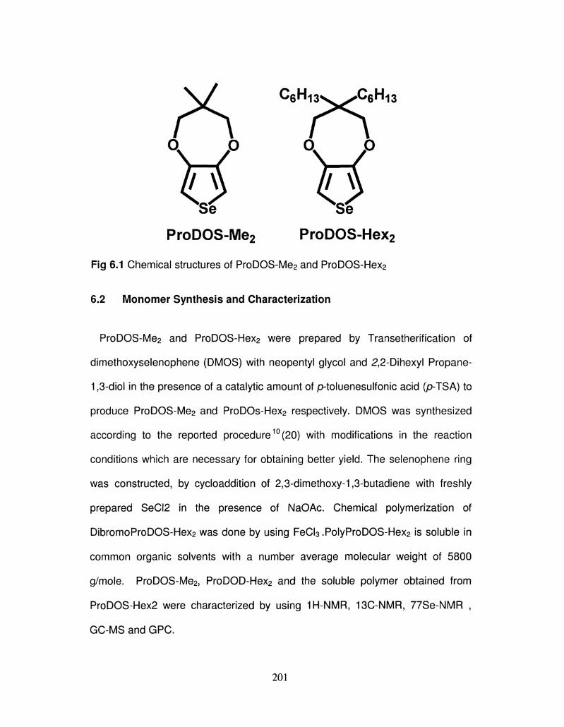
ProDOS-Me2 ProDOS-Hex2
Fig 6.1 Chemical structures of ProDOS-Me2 and ProDOS-Hex2
6.2 Monomer Synthesis and Characterization
ProDOS-Me2 and ProDOS-Hex2 were prepared by Transetherification of
dimethoxyselenophene (DMOS) with neopentyl glycol and 2,2-Dihexyl Propane-
153-diol in the presence of a catalytic amount of p-toluenesulfonic acid (p-TSA) to
produce ProDOS-Me2 and ProDOs-Hex2 respectively. DMOS was synthesized
according to the reported procedure10 (20) with modifications in the reaction
conditions which are necessary for obtaining better yield. The selenophene ring
was constructed, by cycloaddition of 2,3-dimethoxy-1,3-butadiene with freshly
prepared SeCI2 in the presence of NaOAc. Chemical polymerization of
DibromoProDOS-Hex2 was done by using FeCI3.PolyProDOS-Hex2 is soluble in
common organic solvents with a number average molecular weight of 5800
g/mole. ProDOS-Me2j ProDOD-Hex2 and the soluble polymer obtained from
ProDOS-Hex2 were characterized by using 1H-NMR, 13C-NMR, 77Se-NMR ,
GC-MS and GPC.
*
201
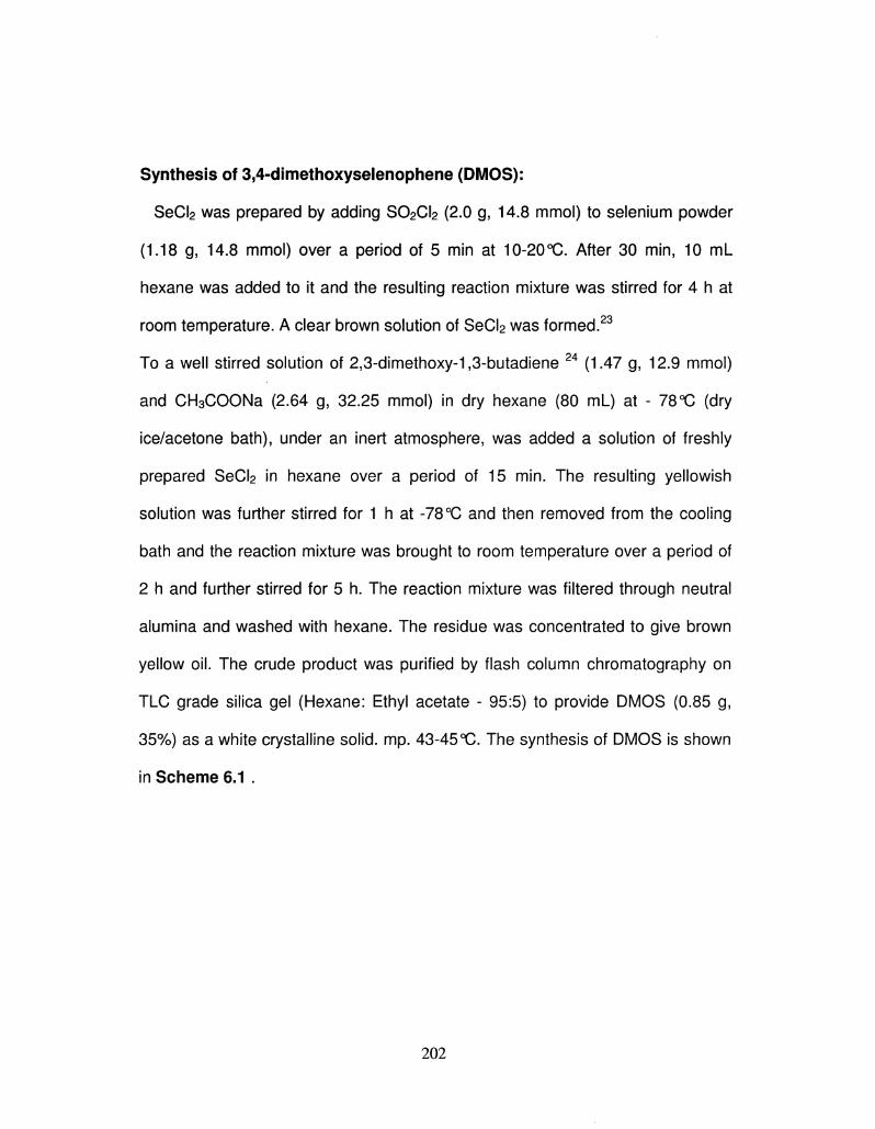
Synthesis of 3,4-dimethoxyselenophene (DMOS):
SeCI2 was prepared by adding S02CI2 (2.0 g, 14.8 mmol) to selenium powder
(1.18 g, 14.8 mmol) over a period of 5 min at 10-20°C. After 30 min, 10 mL
hexane was added to it and the resulting reaction mixture was stirred for 4 h at
room temperature. A clear brown solution of SeCI2 was formed.23
To a well stirred solution of 2,3-dimethoxy-1,3-butadiene 24 (1.47 g, 12.9 mmol)
and CH3COONa (2.64 g, 32.25 mmol) in dry hexane (80 mL) at - 78°C (dry
ice/acetone bath), under an inert atmosphere, was added a solution of freshly
prepared SeCI2 in hexane over a period of 15 min. The resulting yellowish
solution was further stirred for 1 h at -78°C and then removed from the cooling
bath and the reaction mixture was brought to room temperature over a period of
2 h and further stirred for 5 h. The reaction mixture was filtered through neutral
alumina and washed with hexane. The residue was concentrated to give brown
yellow oil. The crude product was purified by flash column chromatography on
TLC grade silica gel (Hexane: Ethyl acetate - 95:5) to provide DMOS (0.85 g,
35%) as a white crystalline solid, mp. 43-45 "C. The synthesis of DMOS is shown
in Scheme 6.1 .
202
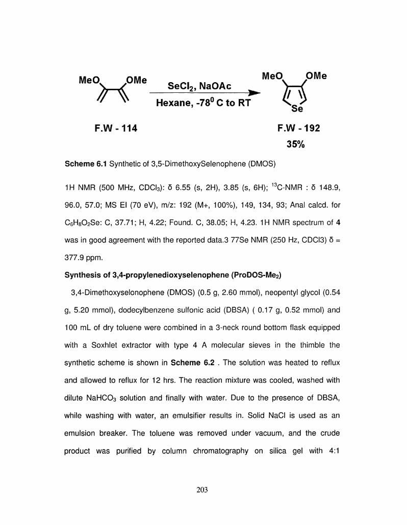
MeOv OMe _ _. M n f t MeO OMe \ / SeCU, NaOAc 7—( #\ 0 ** FA '' v Hexane,-78° C to RT N _ ^
' Se F.W-114 F.W-192
35%
Scheme 6.1 Synthetic of 3,5-DimethoxySelenophene (DMOS)
1H NMR (500 MHz, CDCI3): 5 6.55 (s, 2H), 3.85 (s, 6H); 13C-NMR : 5 148.9,
96.0, 57.0; MS El (70 eV), m/z: 192 (M+, 100%), 149, 134, 93; Anal calcd. for
C6H802Se: C, 37.71; H, 4.22; Found. C, 38.05; H, 4.23. 1H NMR spectrum of 4
was in good agreement with the reported data.3 77Se NMR (250 Hz, CDCI3) 5 =
377.9 ppm.
Synthesis of 3,4-propylenedioxyselenophene (ProDOS-Me2)
3,4-Dimethoxyselonophene (DMOS) (0.5 g, 2.60 mmol), neopentyl glycol (0.54
g, 5.20 mmol), dodecylbenzene sulfonic acid (DBSA) ( 0.17 g, 0.52 mmol) and
100 mL of dry toluene were combined in a 3-neck round bottom flask equipped
with a Soxhlet extractor with type 4 A molecular sieves in the thimble the
synthetic scheme is shown in Scheme 6.2 . The solution was heated to reflux
and allowed to reflux for 12 hrs. The reaction mixture was cooled, washed with
dilute NaHC03 solution and finally with water. Due to the presence of DBSA,
while washing with water, an emulsifier results in. Solid NaCI is used as an
emulsion breaker. The toluene was removed under vacuum, and the crude
product was purified by column chromatography on silica gel with 4:1
203
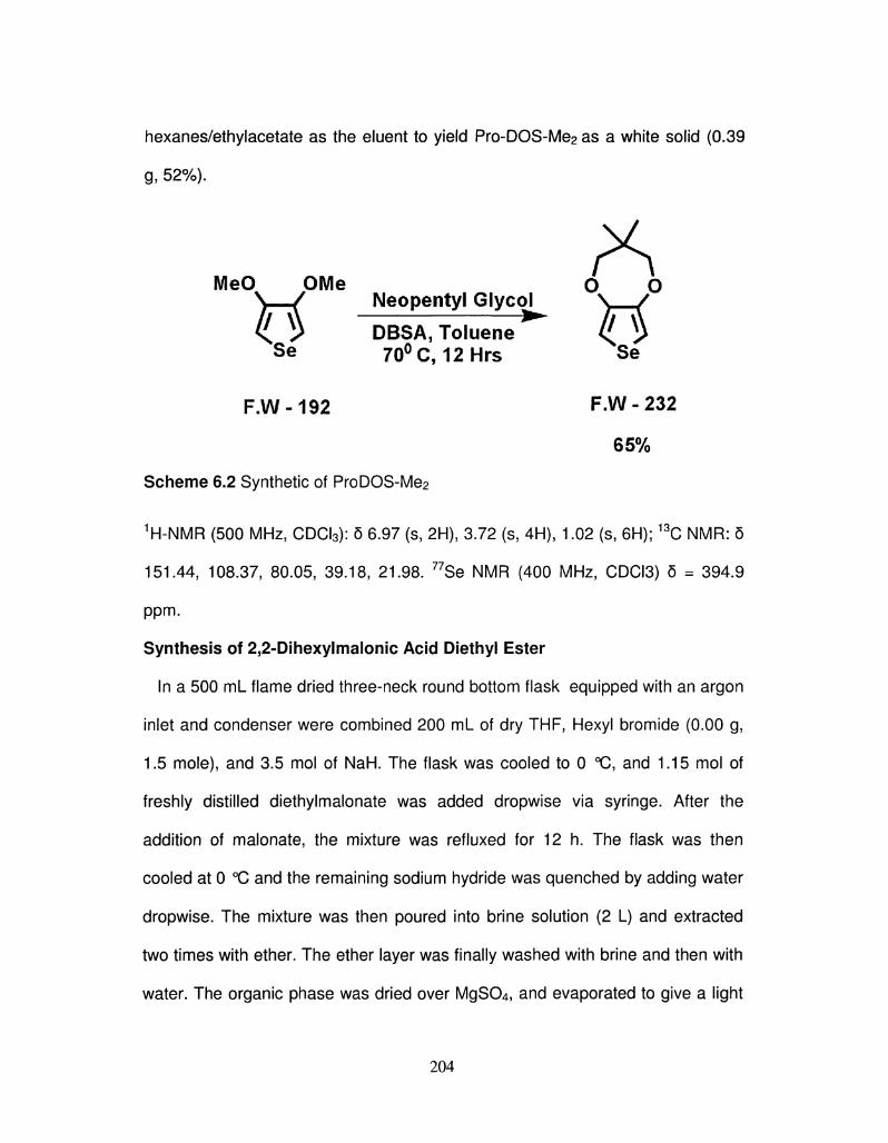
hexanes/ethylacetate as the eluent to yield Pro-DOS-Me2 as a white solid (0.39
g, 52%).
V MeO OMe O O
\ / Neopentyl Glycol^ \ / < ^ DBSA, Toluene ^ >
S e 70°C, 12Hrs Se
F.W-192 F.W-232
65%
Scheme 6.2 Synthetic of ProDOS-Me2
1H-NMR (500 MHz, CDCI3): 5 6.97 (s, 2H), 3.72 (s5 4H)5 1.02 (s, 6H); 13C NMR: 5
151.44, 108.37, 80.05, 39.18, 21.98. 77Se NMR (400 MHz, CDCI3) 6 = 394.9
ppm.
Synthesis of 2,2-Dihexylmalonic Acid Diethyl Ester
In a 500 mL flame dried three-neck round bottom flask equipped with an argon
inlet and condenser were combined 200 mL of dry THF, Hexyl bromide (0.00 g,
1.5 mole), and 3.5 mol of NaH. The flask was cooled to 0 °C, and 1.15 mol of
freshly distilled diethylmalonate was added dropwise via syringe. After the
addition of malonate, the mixture was refluxed for 12 h. The flask was then
cooled at 0 °C and the remaining sodium hydride was quenched by adding water
dropwise. The mixture was then poured into brine solution (2 L) and extracted
two times with ether. The ether layer was finally washed with brine and then with
water. The organic phase was dried over MgS04, and evaporated to give a light
204
yellow liquid. The crude product was further purified by vacuum distillation to
provide 2,2-Dihexylmalonic Acid Diethyl Ester (0.85 g, 70%) as a colorless oil.
p C 2 H 5
C 6 H 1 3 C 6 H 1 3
NaOEt, C6H13-Br C 2 H 5 0 N ^ > C J D C 2 H 5 C6H13-Br C 2 H 5 t X ^ X . ^ O C 2 H ,
1,24 hrs i f I f _ , Ethanol
bc2H5
F.W-160 F.W-328
72%
Scheme 6.3 Synthesis of 2,2-Dihexylmalonic Acid Diethyl Ester
1H NMR (500 MHz, CDCI3): 0.87 (t, 6H), 1.11-1.30 (m, 20H), 1.85 (t, 6H), 4.17
(q, 4H). 13CNMR (500 MHz, CDCI3): 14.08, 14.17, 22.63, 23.94, 29.59, 31.60,
32.21, 57.63, 60.94, 172.09. GC-MS: 311, 272, 244, 173. IR (KBr, cnrV1): 1733,
2859, 2928, 2957.
Synthesis of 2, 2-Dihexyl Propane-1,3-diol
A suspension of lithium aluminum hydride (LAH) (2 g, 52.6 mmol) in dry THF
(20 mL) was stirred at room temperature, and a THF solution of substituted
malonic acid diethyl ester (26.3 mmol) was added dropwise. The reaction was
allowed to reflux for 3 h and was quenched by the addition of cold water. The
compound was extracted in ethyl acetate. The organic layer was washed with
water, dried over Na2S04, and evaporated to produce either a sticky liquid or a
low-melting solid.
205
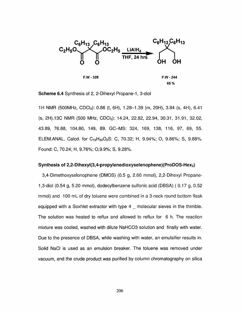
C6H1 3 A H 1 3 CeH^CeH^ C 2 H 5 0 ^ JC ^OC 2 H 5 LiAiH4 ^ * ^
i f T THF,24hrs I 1 0 0 OH OH
F.W - 328 F.W - 244
65%
Scheme 6.4 Synthesis of 2, 2-Dihexyl Propane-1, 3-diol
1H NMR (500MHz, CDCI3): 0.86 (t, 6H)5 1.28-1.39 (m, 20H), 3.84 (s, 4H), 6.41
(s, 2H).13C NMR (500 MHz, CDCI3): 14.24, 22.82, 22.94, 30.31, 31.91, 32.02,
43.89, 76.88, 104.80, 149, 89. GC-MS: 324, 169, 138, 116, 97, 69, 55.
ELEM.ANAL. Calcd. for C19H32O2S: C, 70.32; H, 9.94%; O, 9.86%; S, 9.88%.
Found: C, 70.24; H, 9.76%; 0,9.9%; S, 9.28%.
Synthesis of 2,2-Dihexyl(3,4-propylenedioxyseIenophene)(ProDOS-Hex2)
3,4-Dimethoxyselonophene (DMOS) (0.5 g, 2.60 mmol), 2,2-Dihexyl Propane-
1,3-diol (0.54 g, 5.20 mmol), dodecylbenzene sulfonic acid (DBSA) ( 0.17 g, 0.52
mmol) and 100 mL of dry toluene were combined in a 3-neck round bottom flask
equipped with a Soxhlet extractor with type 4 _ molecular sieves in the thimble.
The solution was heated to reflux and allowed to reflux for 6 h. The reaction
mixture was cooled, washed with dilute NaHC03 solution and finally with water.
Due to the presence of DBSA, while washing with water, an emulsifier results in.
Solid NaCI is used as an emulsion breaker. The toluene was removed under
vacuum, and the crude product was purified by column chromatography on silica
206
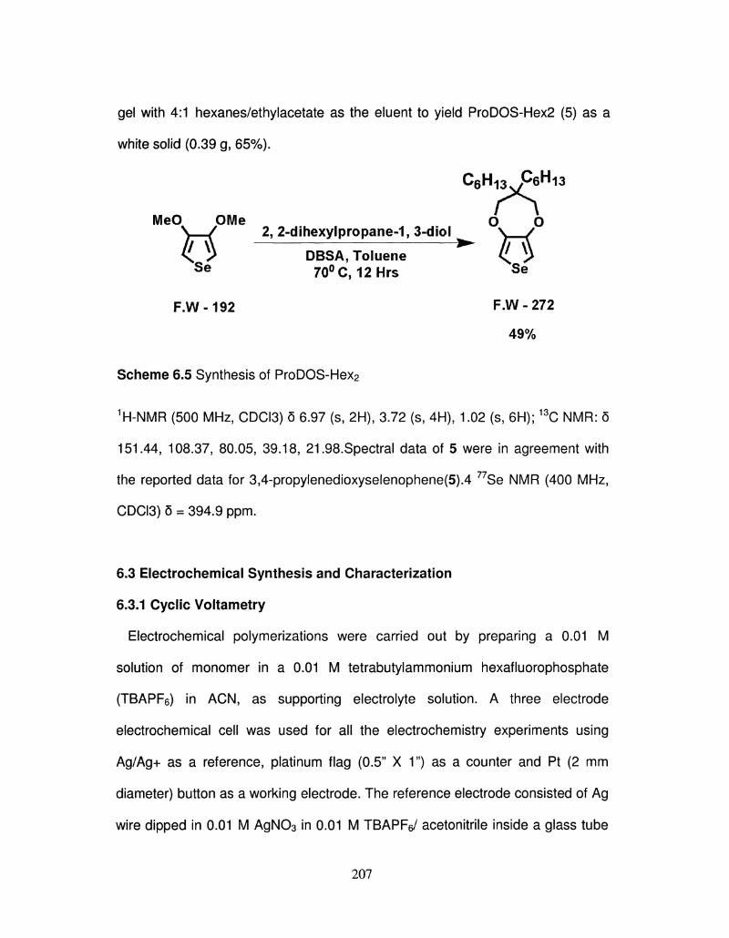
gel with 4:1 hexanes/ethylacetate as the eluent to yield ProDOS-Hex2 (5) as a
white solid (0.39 g, 65%).
c e H i 3 3 p 6 H i 3
MeO OMe O O \ / 2, 2-dihexylpropane-1, 3-diol ^ \ / <l ? DBSA, Toluene ^ i>
Se 70°C, 12Hrs S e
F.W-192 F.W-272
49%
Scheme 6.5 Synthesis of ProDOS-Hex2
1H-NMR (500 MHz, CDCI3) 5 6.97 (s, 2H), 3.72 (s, 4H), 1.02 (s, 6H); 13C NMR: 5
151.44, 108.37, 80.05, 39.18, 21.98.Spectral data of 5 were in agreement with
the reported data for 3,4-propylenedioxyselenophene(5).4 77Se NMR (400 MHz,
CDCI3) 6 = 394.9 ppm.
6.3 Electrochemical Synthesis and Characterization
6.3.1 Cyclic Voltametry
Electrochemical polymerizations were carried out by preparing a 0.01 M
solution of monomer in a 0.01 M tetrabutylammonium hexafluorophosphate
(TBAPF6) in ACN, as supporting electrolyte solution. A three electrode
electrochemical cell was used for all the electrochemistry experiments using
Ag/Ag+ as a reference, platinum flag (0.5" X 1") as a counter and Pt (2 mm
diameter) button as a working electrode. The reference electrode consisted of Ag
wire dipped in 0.01 M AgN03 in 0.01 M TBAPFe/ acetonitrile inside a glass tube
207
fitted with a Vycor tip, which was calibrated to be 0.458 V vs normal hydrogen
electrode (NHE) using ferrocene- ferrocenium redox.
Monomers (ProDOS-Me2 and ProDOS-Hex2) were electrochemically polymerized
from a solution containing 10 mM monomer and 0.1MTBAP as supporting
electrolytes in ACN by the scanning of the potential between - 0.6 and +1.3 V.
This resulted in the formation of polymer films on the electrode. For ProDOS-
Me2j the irreversible oxidation of the monomer was observed at 1.3 V, whereas
for ProDOS-Hex2, irreversible monomer oxidation occurred at 1.2 V. Sharp redox
peaks of the polymer were observed in both cases, being characteristic of the
growth of polymers of alkylenedioxythiophene.The growth of ProDOS-Me2 and
ProDOS-Me2 is shown in Figure 6.2. The polymer oxidation potentials for
PolyProDOS-Me2 and PolyProDOS-Hex2 in the second cycle were observed at -
40 and 0.0 mV respectively. Interestingly, both the polymer showed two sharp
oxidation. This kind of behavior has been observed for other
poly(3,4-alkylenedioxythiophene)s and polyalkylthiophenes.
The first CV scan showed the onset of monomer oxidation at a potential of 0.85
V (vs. Ag/Ag+ reference) with a diffusion limited peak at 1.30V corresponding to
the oxidation of ProDOS-Me2 to its radical cation, and thereafter coupling to form
PProDOS-Me2. These values of ProDOS-Me2 are 0.35 V lowers than that of
corresponding ProDOT-Me2. The low oxidation potential of ProDOS-Me2
prevents over-oxidation of the polymer formed during electrochemical
polymerization, thereby eliminating the possibilities of undesirable side reactions.
Upon scanning in the cathodic direction, a broad reduction process is observed
208
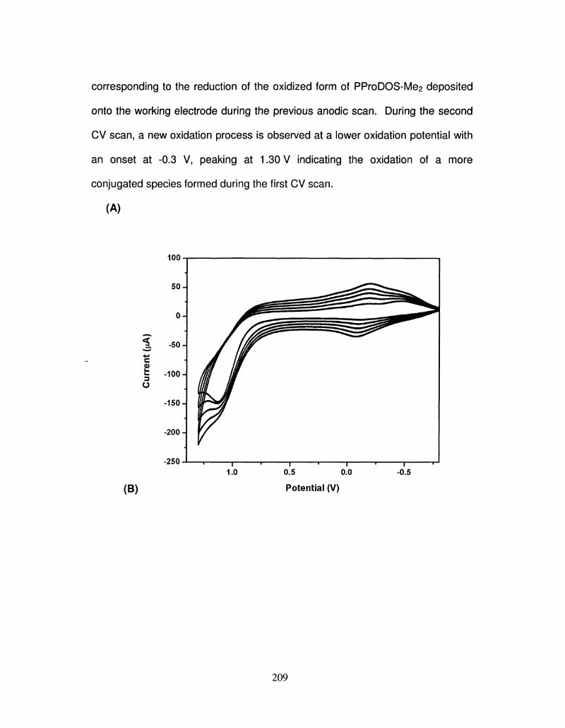
corresponding to the reduction of the oxidized form of PProDOS-Me2 deposited
onto the working electrode during the previous anodic scan. During the second
CV scan, a new oxidation process is observed at a lower oxidation potential with
an onset at -0.3 V, peaking at 1.30 V indicating the oxidation of a more
conjugated species formed during the first CV scan.
(A)
100
c 0) v. 3
o
-100 J
-150 J
-200 H
-250
(B)
0.5 0.0
Potential (V)
0.5
209
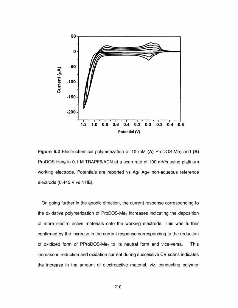
- i — i — i — i — i — i — i — i — i — i — , — i — i — i — i — i — r
1.2 1.0 0.8 0.6 0.4 0.2 0.0 -0.2 -0.4 -0.6
Potential (V)
Figure 6.2 Electrochemical polymerization of 10 mM (A) ProDOS-Me2 and (B)
ProDOS-Hex2 in 0.1 M TBAPF6/ACN at a scan rate of 100 mV/s using platinum
working electrode. Potentials are reported vs Ag/ Ag+ non-aqueous reference
electrode (0.445 V vs NHE).
On going further in the anodic direction, the current response corresponding to
the oxidative polymerization of ProDOS-Me2 increases indicating the deposition
of more electro active materials onto the working electrode. This was further
confirmed by the increase in the current response corresponding to the reduction
of oxidized form of PProDOS-Me2 to its neutral form and vice-versa. This
increase in reduction and oxidation current during successive CV scans indicates
the increase in the amount of electroactive material, viz. conducting polymer
210
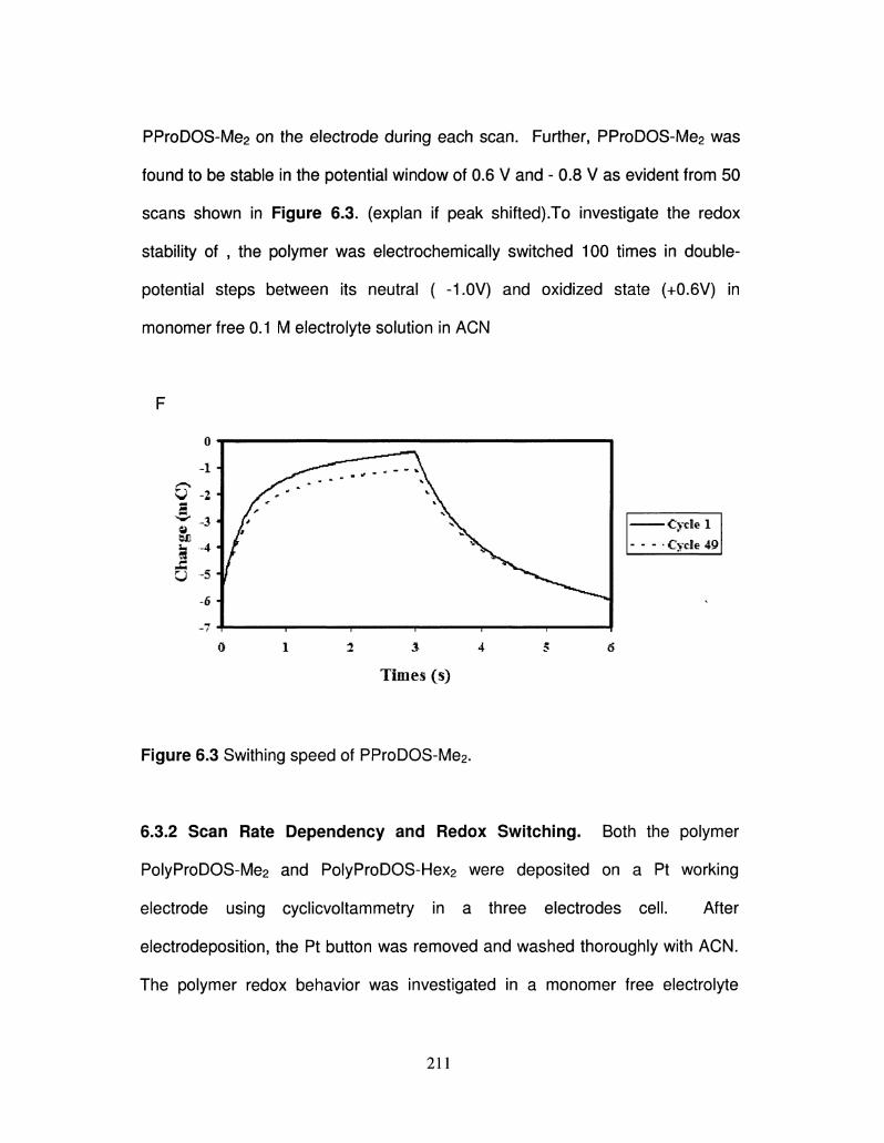
PProDOS-Me2 on the electrode during each scan. Further, PProDOS-Me2 was
found to be stable in the potential window of 0.6 V and - 0.8 V as evident from 50
scans shown in Figure 6-3. (explan if peak shifted).To investigate the redox
stability of , the polymer was electrochemically switched 100 times in double-
potential steps between its neutral ( -1.0V) and oxidized state (+0.6V) in
monomer free 0.1 M electrolyte solution in ACN
F
o i
-i J
y -2 J
6 si 6 J
-7 4-
Figure 6.3 Swithing speed of PProDOS-Me2.
6.3.2 Scan Rate Dependency and Redox Switching. Both the polymer
PolyProDOS-Me2 and PolyProDOS-Hex2 were deposited on a Pt working
electrode using cyclicvoltammetry in a three electrodes cell. After
electrodeposition, the Pt button was removed and washed thoroughly with ACN.
The polymer redox behavior was investigated in a monomer free electrolyte
211
Cycle 1
- Cycle 49
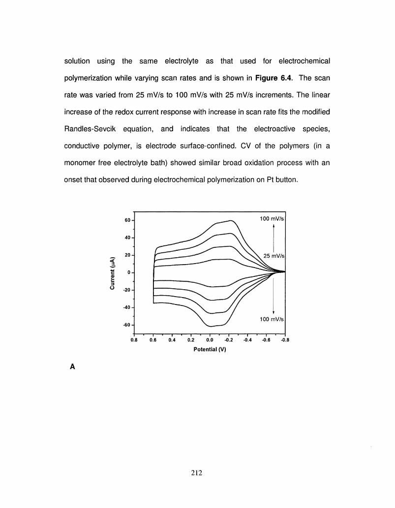
solution using the same electrolyte as that used for electrochemical
polymerization while varying scan rates and is shown in Figure 6-4. The scan
rate was varied from 25 mV/s to 100 mV/s with 25 mV/s increments. The linear
increase of the redox current response with increase in scan rate fits the modified
Randles-Sevcik equation, and indicates that the electroactive species,
conductive polymer, is electrode surface-confined. CV of the polymers (in a
monomer free electrolyte bath) showed similar broad oxidation process with an
onset that observed during electrochemical polymerization on Pt button.
c 0)
60-I
40-1
20-1
0A
-20 H
-40 ^
-60 H
0.8 0.6
100mV/s
25 mV/s
100mV/s
0.4 0.2 0.0 — I • 1 • I •--0.2 -0.4 -0.6 -0.8
Potential (V)
212
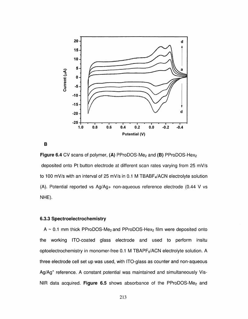
B
c
3
o
1.0 0.8 0.6 0.4 0.2
Potential (V)
Figure 6.4 CV scans of polymer, (A) PProDOS-Me2 and (B) PProDOS-Hex2
deposited onto Pt button electrode at different scan rates varying from 25 mV/s
to 100 mV/s with an interval of 25 mV/s in 0.1 M TBABFVACN electrolyte solution
(A). Potential reported vs Ag/Ag+ non-aqueous reference electrode (0.44 V vs
NHE).
6.3.3 Spectroelectrochemistry
A ~ 0.1 mm thick PProDOS-Me2 and PProDOS-Hex2 film were deposited onto
the working ITO-coated glass electrode and used to perform insitu
optoelectrochemistry in monomer-free 0.1 M TBAPFe/ACN electrolyte solution. A
three electrode cell set up was used, with ITO-glass as counter and non-aqueous
Ag/Ag+ reference. A constant potential was maintained and simultaneously Vis-
NIR data acquired. Figure 6.5 shows absorbance of the PProDOS-Me2 and
213
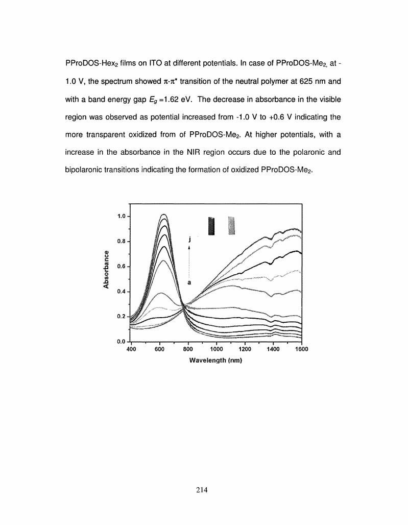
PProDOS-Hex2 films on ITO at different potentials. In case of PProDOS-Me2j at -
1.0 V, the spectrum showed n-n* transition of the neutral polymer at 625 nm and
with a band energy gap Eg =1.62 eV. The decrease in absorbance in the visible
region was observed as potential increased from -1.0 V to +0.6 V indicating the
more transparent oxidized from of PProDOS-Me2. At higher potentials, with a
increase in the absorbance in the NIR region occurs due to the polaronic and
bipolaronic transitions indicating the formation of oxidized PProDOS-Me2.
o.o i » i > ( » i » " i » i i I 400 600 800 1000 1200 1400 1600
Wavelength (nm)
214
Wavelength (nm)
Figure 6.5 In-situ spectroelectrochemistry of (A) PProDOS-Me2 and (B)
PProDOS-Hex2 deposited onto ITO-coated-glass in 0.1 M TBAPF6/ ACN.
Potential reported vs non-aqueous Ag-Ag+ reference electrode (0.445 V vs
NHE).
On the other hand PolyProDOS-Hex2j at -1.0 V, two peaks were observed at
630 and 710 nm due to the vibronic coupling. Upon the stepwise oxidation of the
polymer, the absorbance of the n-%* transition decreased, and the peak due to
the polaron increased at a higher wavelength region. At 0.6 V, the absorbance of
K-K* decreased, and the polymer was transparent and light blue.
215
6.4 Color Cordinates (CIE u v' ) for PProDOS-Me2 and PProDOS-Hex2.
Table 6.1 Situation: Black Body @ 6000K.
Polymer
a) Poly Pro DOS-Me2
b) Poly13ProDOS-
Hex2
u'
0.1859
0.1552
v'
0.4048
0.4358
6.5 Conclusion
In conclusion, we have synthesized the first poly(3,4-
propylene)dioxyselenophene (ProDOS) by taking advantage of a novel method
for efficiently contracting the selenophene ring. Both PEDOS-Me2 and ProDOS-
Hex2 showed low band gap, very high stability in the oxidized state, and a well-
defined spectroelectrochemistry. We have demonstrated that chemical
polymerization of ProDOS-Hex2 could be a viable route for the synthesis of
processable polyselenophenes. We have also shown that polyselenophenes are
excellent candidates for future electrochromic applications. Applications of
PolyProDOS in electrochromic devices and studies of other polyselenophenes
are currently underway in our laboratory
216
6.6 References
1. (a) Chiang, C. K.; Fincher, C. R., Jr.; Park, Y. W.; Heeger, A. J.; Shirakawa,
H.; Louis, E. J.; Gau, S. C; MacDiarmid, A. G. Phys. Rev. Lett. 1977, 39, 1098.
(b) Shirakawa, H.; Louis, E. J.; MacDiarmid, A. G.; Chiang, C. K.; Heeger, A. J. J.
Chem. Soc, Chem. Commun. 1977, 578.
2. (a) Schwendeman, I.; Hwang, J.; Welsh, D. M.; Tanner, D. B.; Reynolds, J. R.
Adv. Mater. 2001, 13, 634. (b) Schottland, P.; Zong, K.; Gaupp, C. L; Thompson,
B. C; Thomas, C. A.; Giurgiu, I.; Hickman, R.; Abboud, K. A.; Reynolds, J. R.
Macromolecules 2000, 33, 7051. (c) Thompson, B. C; Schottland, P.; Zong, K.;
Reynolds, J. R. Chem. Mater. 2000, 12, 1563.
3. (a) McQuade, D. T.; Pullen, A. E.; Swager, T. M. Chem. Rev. 2000, 100,
2537. (b) Yang, J.-S.; Swager, T. M. J. Am. Chem. Soc. 1998, 120, 11864. (c)
Sotzing, G. A.; Briglin, S.; Grubbs, R. H.; Lewis, N. S. Anal. Chem. 2000, 72,
3181.
4. Ma, H.; Chen, B.; Sassa, T.; Dalton, L. R.; Jen, A. K.-Y. J. Am. Chem. Soc.
2001, 123,986.
5. Yu, G.; Heeger, A. J. Synth. Met. 1997, 85, 1183.
6. Ferraris, J. P.; Eissa, M. M.; Brotherston, I. D.; Loveday, D. C. Chem. Mater.
1998,11,3528.
7. Jonas, F.; Heywang, G. Electrochim. Acta 1994, 39, 1345.
8. Perucki, M.; Chandrasekhar, P. Synth. Met. 2001, 119, 385.
217
9. (a) Brabec, C. J.; Sariciftci, N. S.; Hummelen, J. C. Adv. Func. Mater. 2001,
11, 15. (b) Henckens, A.; Knipper, M.; Polec, I.; Manca, J.; Lutsen, L;
Vanderzande, D. Thin Solid Films 2004, 451 & 572.
10. For recent review on poly(3,4-ethylenedioxythiophene) see: Groenendaal, L;
Jonas, F.; Freitag, D.; Pielartzik, H.; Reynolds, J. R. AdV.Mater. 2000, 12, 481.
11. Reynolds, J. R.; Kumar, A.; Reddinger, J. L; Sankaran, B.; Sapp, S.A.;
Sotzing, G. A. Synth. Met. 1997, 85, 1295.
12. Dietrich, M.; Heinze, J.; Heywang, G.; Jonas, F. J. Electroanal. Chem. 1994,
369, 87.
13. Kumar, A.; Welsh, D. M.; Morvant, M. C; Piroux, F.; Abboud, K. A.;
Reynolds, J. R. Chem. Mater. 1998, 10, 896.
14. (a) Welsh, D. M.; Kumar, A.; Morvant M. C; Reynolds, J. R. Synth. Met.
1999, 102, 967; (b) Welsh, D. M.; Kumar, A.; Meijer, E. W.; Reynolds, J. R. Adv.
Mater. 1999, / / , 1379; (c) Welsh, D. M.; Kloeppner, L J.; Madrigal, L; Pinto, M.
R.; Thompson, B. C; Schanze, K. S.; Abboud, K. A.; Powell, D.; Reynolds, J. R.
Macromolecules 2002, 35, 6517.
15. K. Krishnamoorthy, A. V. Ambade, M. Kanungo, A. Q. Contractor and A.
Kumar, J. Mater. Chem. 2001, 11, 2909.
16. Welsh, D.M.; Kumar, A.; Meijer, E. W.; Reynolds, J. R. Adv. Mater. 1999, 11,
1379.
17. Kobayashi, H.; Cui, H. Chem. ReV. 2004, 104, 5265.
18. a) Zade, S. S.; Bendikov, M. Org. Lett. 2006, 8, 5243. (b) Salzner, U.;
Lagowski, J. B.; Pickup, P. G.; Poirier, R. A. Synth. Met. 1998, 96,177.
218
19. Patra, A.; Wijsboom, Y. H.; Zade, S. S.; Li, M.; Sheynin, Y.; Leitus, G.;
Bendikov, M. J. Am. Chem. Soc. 2008, 130, 6734.
20. Aqad, E.; Lakshmikantham, M. V.; Cava, M. P. Org. Lett. 2001, 3, 4283.
21. Li, M.; Patra, A.; Sheynin, Y.; Bendikov, M. Adv. Mater. 2009, 21,1707.
22. M. Li, Y. Sheynin, A. Patra, M. Bendikov, Chem. Mater. 2009, 21, 2482.
219