Embed Size (px)
Citation preview
978-1-4799-2722-7/13/$31.00 ©2013 IEEE
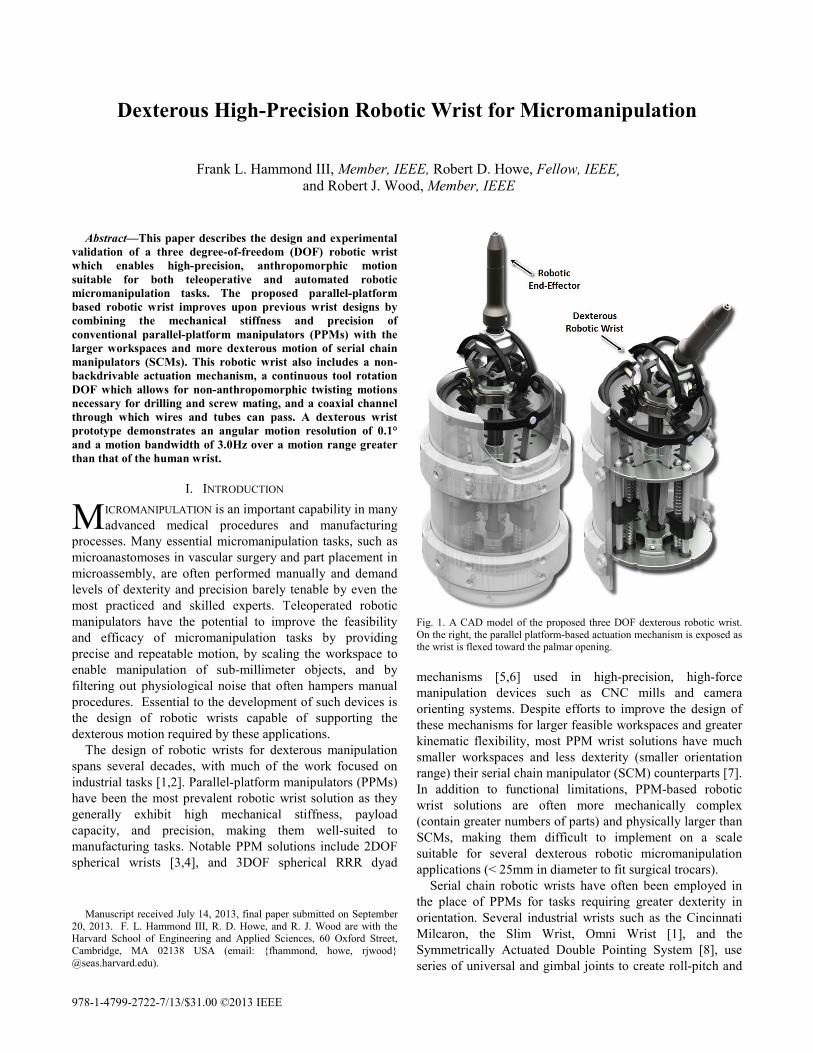
Abstract—This paper describes the design and experimental validation of a three degree-of-freedom (DOF) robotic wrist which enables high-precision, anthropomorphic motion suitable for both teleoperative and automated robotic micromanipulation tasks. The proposed parallel-platform based robotic wrist improves upon previous wrist designs by combining the mechanical stiffness and precision of conventional parallel-platform manipulators (PPMs) with the larger workspaces and more dexterous motion of serial chain manipulators (SCMs). This robotic wrist also includes a non-backdrivable actuation mechanism, a continuous tool rotation DOF which allows for non-anthropomorphic twisting motions necessary for drilling and screw mating, and a coaxial channel through which wires and tubes can pass. A dexterous wrist prototype demonstrates an angular motion resolution of 0.1° and a motion bandwidth of 3.0Hz over a motion range greater than that of the human wrist.
I. INTRODUCTION ICROMANIPULATION is an important capability in many advanced medical procedures and manufacturing
processes. Many essential micromanipulation tasks, such as microanastomoses in vascular surgery and part placement in microassembly, are often performed manually and demand levels of dexterity and precision barely tenable by even the most practiced and skilled experts. Teleoperated robotic manipulators have the potential to improve the feasibility and efficacy of micromanipulation tasks by providing precise and repeatable motion, by scaling the workspace to enable manipulation of sub-millimeter objects, and by filtering out physiological noise that often hampers manual procedures. Essential to the development of such devices is the design of robotic wrists capable of supporting the dexterous motion required by these applications.
The design of robotic wrists for dexterous manipulation spans several decades, with much of the work focused on industrial tasks [1,2]. Parallel-platform manipulators (PPMs) have been the most prevalent robotic wrist solution as they generally exhibit high mechanical stiffness, payload capacity, and precision, making them well-suited to manufacturing tasks. Notable PPM solutions include 2DOF spherical wrists [3,4], and 3DOF spherical RRR dyad
Manuscript received July 14, 2013, final paper submitted on September
20, 2013. F. L. Hammond III, R. D. Howe, and R. J. Wood are with the Harvard School of Engineering and Applied Sciences, 60 Oxford Street, Cambridge, MA 02138 USA (email: {fhammond, howe, rjwood} @seas.harvard.edu).
Fig. 1. A CAD model of the proposed three DOF dexterous robotic wrist. On the right, the parallel platform-based actuation mechanism is exposed as the wrist is flexed toward the palmar opening. mechanisms [5,6] used in high-precision, high-force manipulation devices such as CNC mills and camera orienting systems. Despite efforts to improve the design of these mechanisms for larger feasible workspaces and greater kinematic flexibility, most PPM wrist solutions have much smaller workspaces and less dexterity (smaller orientation range) their serial chain manipulator (SCM) counterparts [7]. In addition to functional limitations, PPM-based robotic wrist solutions are often more mechanically complex (contain greater numbers of parts) and physically larger than SCMs, making them difficult to implement on a scale suitable for several dexterous robotic micromanipulation applications (< 25mm in diameter to fit surgical trocars).
Serial chain robotic wrists have often been employed in the place of PPMs for tasks requiring greater dexterity in orientation. Several industrial wrists such as the Cincinnati Milcaron, the Slim Wrist, Omni Wrist [1], and the Symmetrically Actuated Double Pointing System [8], use series of universal and gimbal joints to create roll-pitch and
Dexterous High-Precision Robotic Wrist for Micromanipulation
Frank L. Hammond III, Member, IEEE, Robert D. Howe, Fellow, IEEE¸ and Robert J. Wood, Member, IEEE
M
roll-pitch-yaw wrists capable of dexterous motion over large, anthropomorphic workspaces. These mechanisms boast greater kinematic flexibility than PPM wrists and can often be designed in small form factors. However, the serial wrists suffer from a lack of mechanical stiffness, low motion bandwidth due to higher inertia (actuators located distally, throughout chain), and kinematic singularities. Recent dexterous robotic wrists designed for surgery [9] alleviate bandwidth and mechanical design issues by employing cable-pulley mechanisms which allow actuators to be mounted proximal to the wrist mechanism, reducing distal inertia and easing design considerations for compactness (remote actuation). Cable driven wrists, however, often require complicated transmission systems and control schemes to maintain cable tension, reduce system backslash, and modulate actuation forces, and are also less robust than rigid gear-based systems due to cycle fatigue susceptibility.
This paper describes the design of a hybrid 3-DOF robotic wrist that integrates the mechanical stiffness and precision of PPMs with the dexterous motion and large workspace of SCMs. The proposed robotic wrist design is comprised of a parallel-platform based, non-backdrivable actuation system in series with a gear-based transmission which converts high-resolution linear motion into dexterous, high-resolution angular motion (Fig 1). In addition to being precise, mechanically robust, and kinematically flexible, the proposed wrist also provides a continuous axial rotation DOF and a coaxial channel through which tubes and wires can be routed to power various end-effector types. This robotic wrist is designed for manufacturing and assembly and its architecture is parameterized to enable selection of the actuator or transmission components to meet certain performance goals and accommodate design limitations.
Section II describes the kinematics that govern the relationship between the wrist actuation mechanisms’ linear motion input and angular motion output, as well as the design of the mechanisms comprising the wrist transmission. Section III analyzes the kinematic dexterity and workspace of the proposed robotic wrist. Section IV details the fabrication of a wrist prototype and experimental validation of the wrist’s mechanical and kinematic design. Section V summarizes experimental results, and Section VI discusses conclusions and future research directions.
II. MECHANICAL DESIGN
A. General Mechanism Morphology The proposed wrist design (Fig. 2), like several previous
robotic wrist designs [10,11], is inspired in part by biological manipulators, such as the human arm, which can be described as serial chains of parallel or closed chain linkages [12-15]. Parallel linkages alone provide precise motion and high mechanical rigidity in small workspaces but, when placed in series, can provide similar levels of precision and rigidity with greater dexterity and larger work volumes.
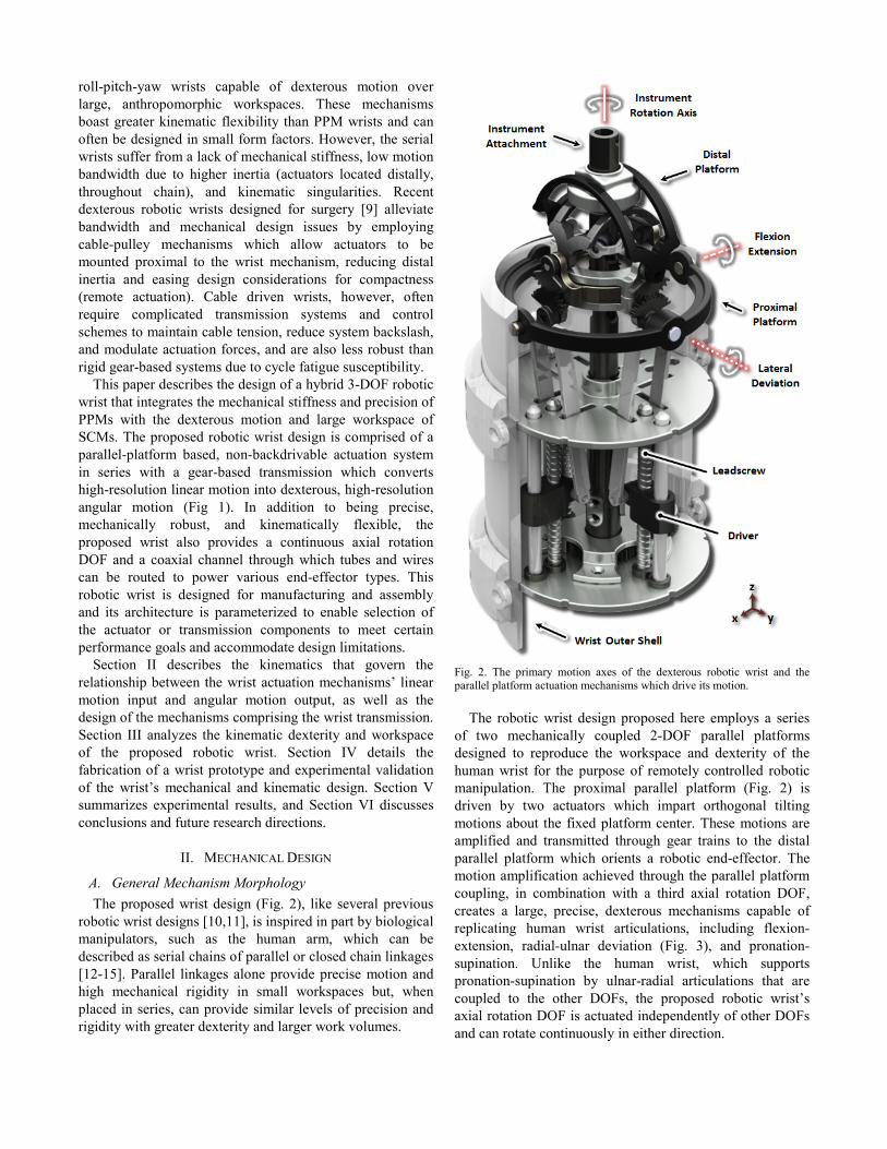
Fig. 2. The primary motion axes of the dexterous robotic wrist and the parallel platform actuation mechanisms which drive its motion.
The robotic wrist design proposed here employs a series
of two mechanically coupled 2-DOF parallel platforms designed to reproduce the workspace and dexterity of the human wrist for the purpose of remotely controlled robotic manipulation. The proximal parallel platform (Fig. 2) is driven by two actuators which impart orthogonal tilting motions about the fixed platform center. These motions are amplified and transmitted through gear trains to the distal parallel platform which orients a robotic end-effector. The motion amplification achieved through the parallel platform coupling, in combination with a third axial rotation DOF, creates a large, precise, dexterous mechanisms capable of replicating human wrist articulations, including flexion-extension, radial-ulnar deviation (Fig. 3), and pronation-supination. Unlike the human wrist, which supports pronation-supination by ulnar-radial articulations that are coupled to the other DOFs, the proposed robotic wrist’s axial rotation DOF is actuated independently of other DOFs and can rotate continuously in either direction.
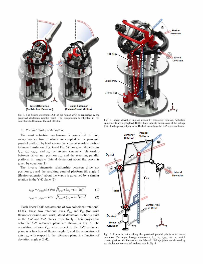
Fig. 3. The flexion-extension DOF of the human wrist as replicated by the proposed dexterous robotic wrist. The components highlighted in red contribute to flexion of the end-effector.
B. Parallel Platform Actuation The wrist actuation mechanism is comprised of three
rotary motors, two of which are coupled to the proximal parallel platform by lead screws that convert revolute motion to linear translation (Fig. 4 and Fig. 5). For given dimensions larm, zax, rpltfrm, and xn, the inverse kinematic relationship between driver nut position zn,φ and the resulting parallel platform tilt angle φ (lateral deviation) about the y-axis is given by equation (1).
The inverse kinematic relationship between drive nut position zn,θ and the resulting parallel platform tilt angle θ (flexion-extension) about the x-axis is governed by a similar relation in the Y-Z plane (2).
2 2
, sin( ) ( sin ( ))n pltfm arm nz r l xϕ ϕ ϕ= ± + − (1)
2 2, sin( ) ( sin ( ))n pltfm arm nz r l yθ θ θ= ± + − (2)
Each linear DOF actuates one of two coincident rotational
DOFs. These two rotational axes, flex and dev (for wrist flexion-extension and wrist lateral deviation motions) exist in the X-Z and Y-Z planes respectively. Their projections onto the X-Y reference plane are shown in Fig. 6. The orientation of axis dev with respect to the X-Y reference plane is a function of flexion angle θ, and the orientation of axis flex with respect to the reference plane is a function of deviation angle φ (3,4).
Fig. 4. Lateral deviation motion driven by leadscrew rotation. Actuation components are highlighted. Dotted lines indicate dimensions of the linkage that tilts the proximal platform. Dashed lines show the X-Z reference frame.
Fig. 5. Linear actuator tilting the proximal parallel platform in lateral deviation. The major linkage dimensions, larm, zax, rpltfrm, and xn, which dictate platform tilt kinematics, are labeled. Linkage joints are denoted by red circles and correspond to those seen in Fig. 4.
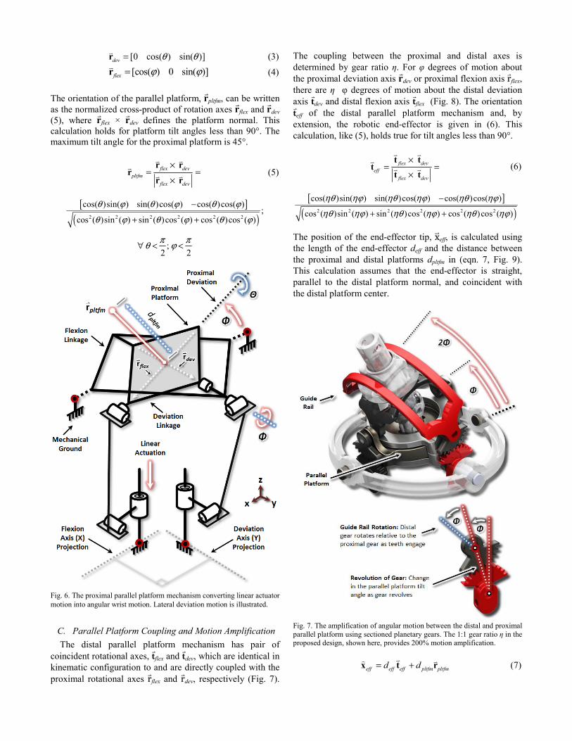
[0 cos( ) sin( )]dev θ θ=r (3) [cos( ) 0 sin( )]flex ϕ ϕ=r (4)
The orientation of the parallel platform, pltfm, can be written as the normalized cross-product of rotation axes flex and dev (5), where flex × dev defines the platform normal. This calculation holds for platform tilt angles less than 90°. The maximum tilt angle for the proximal platform is 45°.
flex dev
pltfmflex dev
×= =
×
r rr
r r (5)
[ ]( )2 2 2 2 2 2
cos( )sin( ) sin( )cos( ) cos( )cos( );
cos ( )sin ( ) sin ( )cos ( ) cos ( )cos ( )
θ ϕ θ ϕ θ ϕ
θ ϕ θ ϕ θ ϕ
−
+ +
;2 2π πθ ϕ∀ < <
Fig. 6. The proximal parallel platform mechanism converting linear actuator motion into angular wrist motion. Lateral deviation motion is illustrated.
C. Parallel Platform Coupling and Motion Amplification The distal parallel platform mechanism has pair of
coincident rotational axes, flex and dev, which are identical in kinematic configuration to and are directly coupled with the proximal rotational axes rflex and rdev, respectively (Fig. 7).
The coupling between the proximal and distal axes is determined by gear ratio η. For φ degrees of motion about the proximal deviation axis dev or proximal flexion axis rflex, there are η�φ degrees of motion about the distal deviation axis dev and distal flexion axis flex (Fig. 8). The orientation
eff of the distal parallel platform mechanism and, by extension, the robotic end-effector is given in (6). This calculation, like (5), holds true for tilt angles less than 90°.
flex dev
effflex dev
×= =
×
t tt
t t (6)
[ ]( )2 2 2 2 2 2
cos( )sin( ) sin( )cos( ) cos( )cos( )
cos ( )sin ( ) sin ( )cos ( ) cos ( )cos ( )
ηθ ηϕ ηθ ηϕ ηθ ηϕ
ηθ ηϕ ηθ ηϕ ηθ ηϕ
−
+ +
The position of the end-effector tip, xeff, is calculated using the length of the end-effector deff and the distance between the proximal and distal platforms dpltfm in (eqn. 7, Fig. 9). This calculation assumes that the end-effector is straight, parallel to the distal platform normal, and coincident with the distal platform center.
Fig. 7. The amplification of angular motion between the distal and proximal parallel platform using sectioned planetary gears. The 1:1 gear ratio η in the proposed design, shown here, provides 200% motion amplification.
eff eff eff pltfm pltfmd d= +x t r (7)
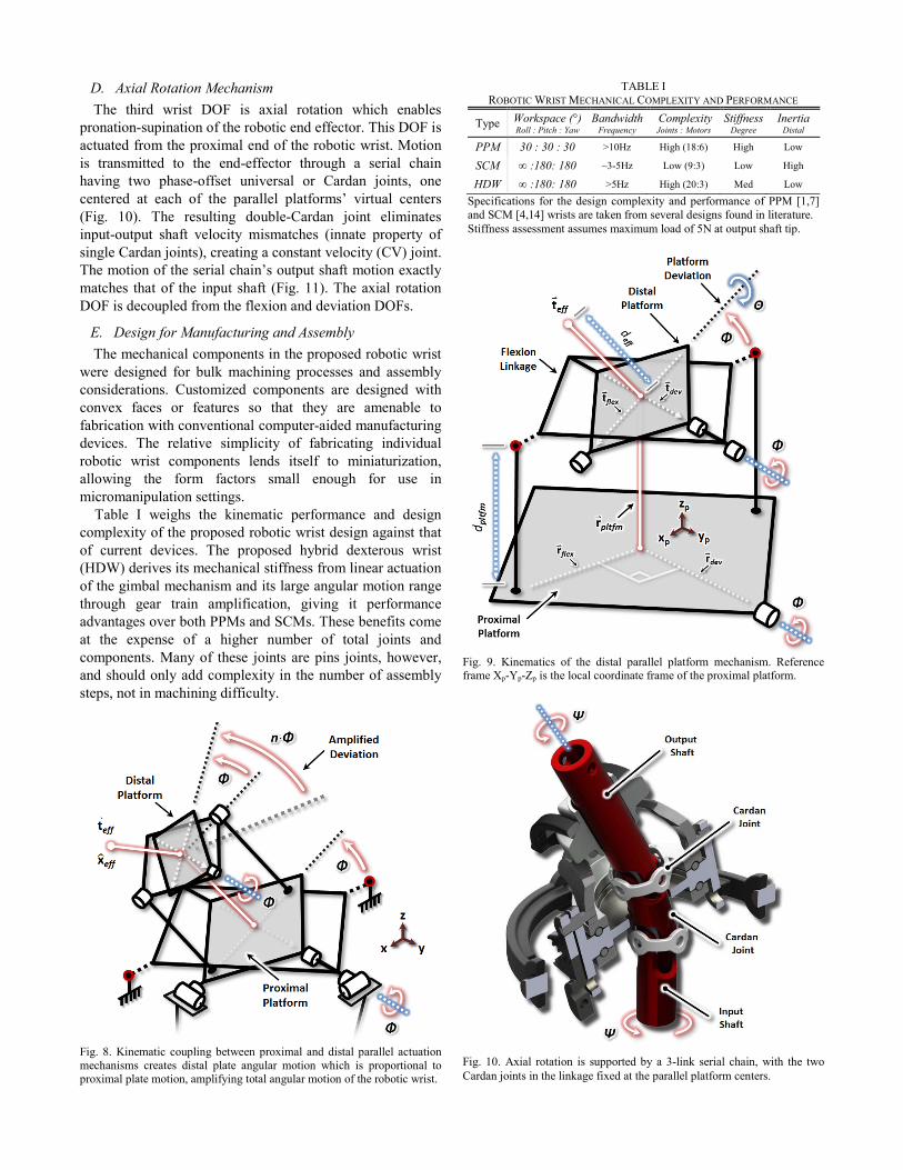
D. Axial Rotation Mechanism The third wrist DOF is axial rotation which enables
pronation-supination of the robotic end effector. This DOF is actuated from the proximal end of the robotic wrist. Motion is transmitted to the end-effector through a serial chain having two phase-offset universal or Cardan joints, one centered at each of the parallel platforms’ virtual centers (Fig. 10). The resulting double-Cardan joint eliminates input-output shaft velocity mismatches (innate property of single Cardan joints), creating a constant velocity (CV) joint. The motion of the serial chain’s output shaft motion exactly matches that of the input shaft (Fig. 11). The axial rotation DOF is decoupled from the flexion and deviation DOFs.
E. Design for Manufacturing and Assembly The mechanical components in the proposed robotic wrist
were designed for bulk machining processes and assembly considerations. Customized components are designed with convex faces or features so that they are amenable to fabrication with conventional computer-aided manufacturing devices. The relative simplicity of fabricating individual robotic wrist components lends itself to miniaturization, allowing the form factors small enough for use in micromanipulation settings.
Table I weighs the kinematic performance and design complexity of the proposed robotic wrist design against that of current devices. The proposed hybrid dexterous wrist (HDW) derives its mechanical stiffness from linear actuation of the gimbal mechanism and its large angular motion range through gear train amplification, giving it performance advantages over both PPMs and SCMs. These benefits come at the expense of a higher number of total joints and components. Many of these joints are pins joints, however, and should only add complexity in the number of assembly steps, not in machining difficulty.
Fig. 8. Kinematic coupling between proximal and distal parallel actuation mechanisms creates distal plate angular motion which is proportional to proximal plate motion, amplifying total angular motion of the robotic wrist.
Fig. 9. Kinematics of the distal parallel platform mechanism. Reference frame Xp-Yp-Zp is the local coordinate frame of the proximal platform.
Fig. 10. Axial rotation is supported by a 3-link serial chain, with the two Cardan joints in the linkage fixed at the parallel platform centers.
TABLE I ROBOTIC WRIST MECHANICAL COMPLEXITY AND PERFORMANCE
Type Workspace (°)Roll : Pitch : Yaw
Bandwidth Frequency
Complexity Joints : Motors
StiffnessDegree
Inertia Distal
PPM 30 : 30 : 30 >10Hz High (18:6) High Low
SCM ∞ :180: 180 ~3-5Hz Low (9:3) Low High
HDW ∞ :180: 180 >5Hz High (20:3) Med Low
Specifications for the design complexity and performance of PPM [1,7] and SCM [4,14] wrists are taken from several designs found in literature. Stiffness assessment assumes maximum load of 5N at output shaft tip.
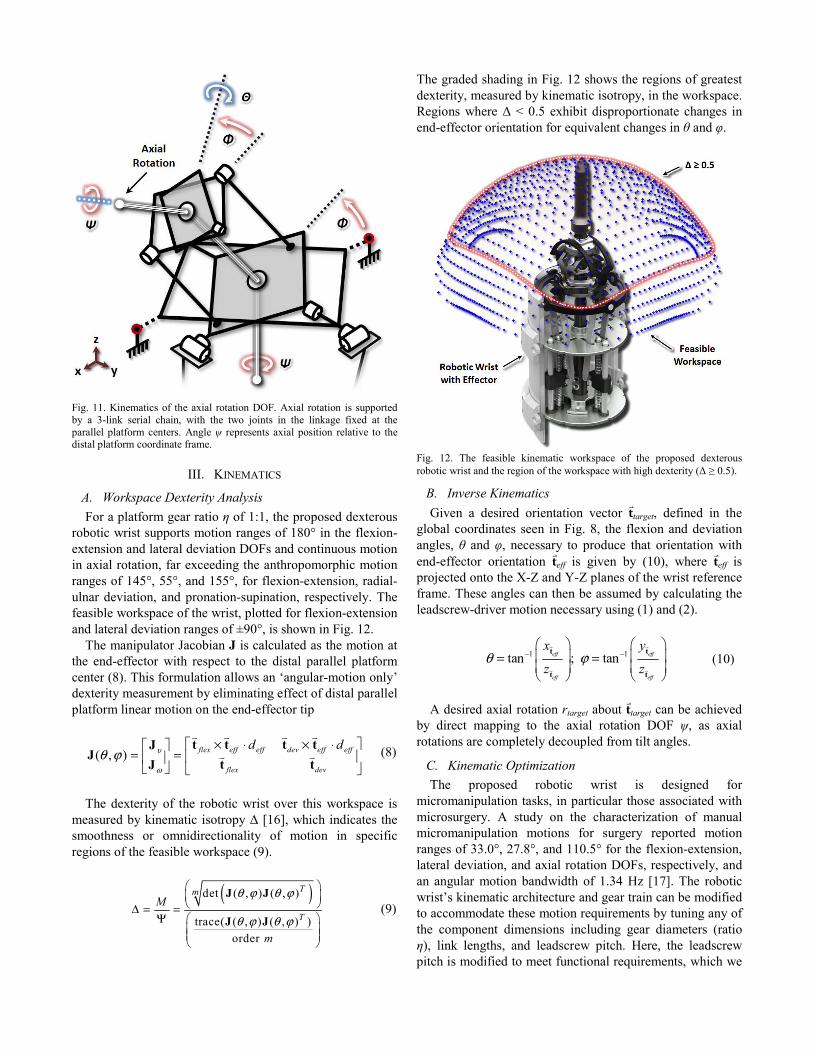
Fig. 11. Kinematics of the axial rotation DOF. Axial rotation is supported by a 3-link serial chain, with the two joints in the linkage fixed at the parallel platform centers. Angle ψ represents axial position relative to the distal platform coordinate frame.
III. KINEMATICS
A. Workspace Dexterity Analysis For a platform gear ratio η of 1:1, the proposed dexterous
robotic wrist supports motion ranges of 180° in the flexion-extension and lateral deviation DOFs and continuous motion in axial rotation, far exceeding the anthropomorphic motion ranges of 145°, 55°, and 155°, for flexion-extension, radial-ulnar deviation, and pronation-supination, respectively. The feasible workspace of the wrist, plotted for flexion-extension and lateral deviation ranges of ±90°, is shown in Fig. 12.
The manipulator Jacobian J is calculated as the motion at the end-effector with respect to the distal parallel platform center (8). This formulation allows an ‘angular-motion only’ dexterity measurement by eliminating effect of distal parallel platform linear motion on the end-effector tip
( , ) flex eff eff dev eff eff
flex dev
d dυ
ω
θ ϕ× ⋅ × ⋅⎡ ⎤⎡ ⎤
= = ⎢ ⎥⎢ ⎥⎣ ⎦ ⎣ ⎦
t t t tJJ
t tJ (8)
The dexterity of the robotic wrist over this workspace is
measured by kinematic isotropy Δ [16], which indicates the smoothness or omnidirectionality of motion in specific regions of the feasible workspace (9).
( )det ( , ) ( , )
trace( ( , ) ( , ) )order
Tm
TM
m
θ ϕ θ ϕ
θ ϕ θ ϕ
⎛ ⎞⎜ ⎟⎝ ⎠Δ = =
Ψ ⎛ ⎞⎜ ⎟⎜ ⎟⎝ ⎠
J J
J J (9)
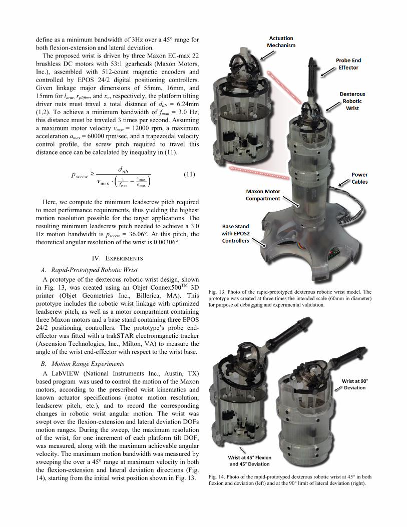
The graded shading in Fig. 12 shows the regions of greatest dexterity, measured by kinematic isotropy, in the workspace. Regions where Δ < 0.5 exhibit disproportionate changes in end-effector orientation for equivalent changes in θ and φ.
Fig. 12. The feasible kinematic workspace of the proposed dexterous robotic wrist and the region of the workspace with high dexterity (Δ ≥ 0.5).
B. Inverse Kinematics Given a desired orientation vector target, defined in the
global coordinates seen in Fig. 8, the flexion and deviation angles, θ and φ, necessary to produce that orientation with end-effector orientation eff is given by (10), where eff is projected onto the X-Z and Y-Z planes of the wrist reference frame. These angles can then be assumed by calculating the leadscrew-driver motion necessary using (1) and (2).
1 1tan ; taneff eff
eff eff
x y
z zθ ϕ− −
⎛ ⎞ ⎛ ⎞⎜ ⎟ ⎜ ⎟= =⎜ ⎟ ⎜ ⎟⎝ ⎠ ⎝ ⎠
t t
t t
(10)
A desired axial rotation rtarget about target can be achieved
by direct mapping to the axial rotation DOF ψ, as axial rotations are completely decoupled from tilt angles.
C. Kinematic Optimization The proposed robotic wrist is designed for
micromanipulation tasks, in particular those associated with microsurgery. A study on the characterization of manual micromanipulation motions for surgery reported motion ranges of 33.0°, 27.8°, and 110.5° for the flexion-extension, lateral deviation, and axial rotation DOFs, respectively, and an angular motion bandwidth of 1.34 Hz [17]. The robotic wrist’s kinematic architecture and gear train can be modified to accommodate these motion requirements by tuning any of the component dimensions including gear diameters (ratio η), link lengths, and leadscrew pitch. Here, the leadscrew pitch is modified to meet functional requirements, which we
define as a minimum bandwidth of 3Hz over a 45° range for both flexion-extension and lateral deviation.
The proposed wrist is driven by three Maxon EC-max 22 brushless DC motors with 53:1 gearheads (Maxon Motors, Inc.), assembled with 512-count magnetic encoders and controlled by EPOS 24/2 digital positioning controllers. Given linkage major dimensions of 55mm, 16mm, and 15mm for larm, rpltfrm, and xn, respectively, the platform tilting driver nuts must travel a total distance of dtilt = 6.24mm (1,2). To achieve a minimum bandwidth of fman = 3.0 Hz, this distance must be traveled 3 times per second. Assuming a maximum motor velocity vmax = 12000 rpm, a maximum acceleration amax = 60000 rpm/sec, and a trapezoidal velocity control profile, the screw pitch required to travel this distance once can be calculated by inequality in (11).
( )max
max
1max man
tiltscrew v
f a
dpv
≥⋅ −
(11)
Here, we compute the minimum leadscrew pitch required
to meet performance requirements, thus yielding the highest motion resolution possible for the target applications. The resulting minimum leadscrew pitch needed to achieve a 3.0 Hz motion bandwidth is pscrew = 36.06°. At this pitch, the theoretical angular resolution of the wrist is 0.00306°.
IV. EXPERIMENTS
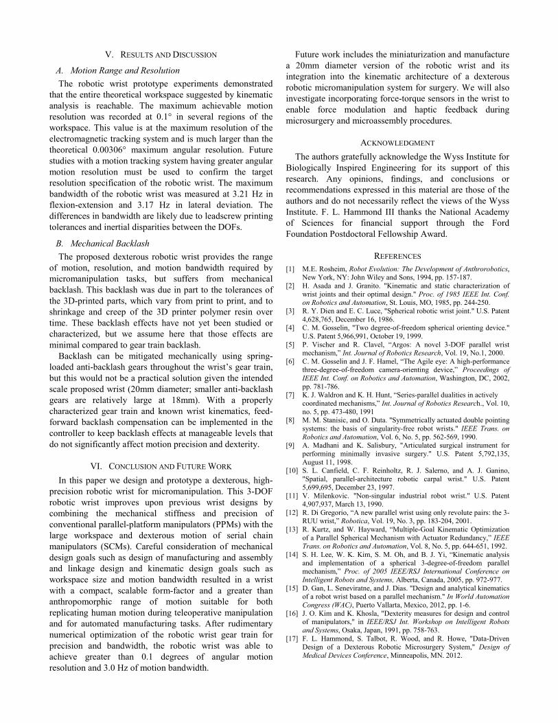
A. Rapid-Prototyped Robotic Wrist A prototype of the dexterous robotic wrist design, shown
in Fig. 13, was created using an Objet Connex500TM 3D printer (Objet Geometries Inc., Billerica, MA). This prototype includes the robotic wrist linkage with optimized leadscrew pitch, as well as a motor compartment containing three Maxon motors and a base stand containing three EPOS 24/2 positioning controllers. The prototype’s probe end-effector was fitted with a trakSTAR electromagnetic tracker (Ascension Technologies, Inc., Milton, VA) to measure the angle of the wrist end-effector with respect to the wrist base.
B. Motion Range Experiments A LabVIEW (National Instruments Inc., Austin, TX)
based program was used to control the motion of the Maxon motors, according to the prescribed wrist kinematics and known actuator specifications (motor motion resolution, leadscrew pitch, etc.), and to record the corresponding changes in robotic wrist angular motion. The wrist was swept over the flexion-extension and lateral deviation DOFs motion ranges. During the sweep, the maximum resolution of the wrist, for one increment of each platform tilt DOF, was measured, along with the maximum achievable angular velocity. The maximum motion bandwidth was measured by sweeping the over a 45° range at maximum velocity in both the flexion-extension and lateral deviation directions (Fig. 14), starting from the initial wrist position shown in Fig. 13.
Fig. 13. Photo of the rapid-prototyped dexterous robotic wrist model. The prototype was created at three times the intended scale (60mm in diameter) for purpose of debugging and experimental validation.
Fig. 14. Photo of the rapid-prototyped dexterous robotic wrist at 45° in both flexion and deviation (left) and at the 90° limit of lateral deviation (right).
V. RESULTS AND DISCUSSION
A. Motion Range and Resolution The robotic wrist prototype experiments demonstrated
that the entire theoretical workspace suggested by kinematic analysis is reachable. The maximum achievable motion resolution was recorded at 0.1° in several regions of the workspace. This value is at the maximum resolution of the electromagnetic tracking system and is much larger than the theoretical 0.00306° maximum angular resolution. Future studies with a motion tracking system having greater angular motion resolution must be used to confirm the target resolution specification of the robotic wrist. The maximum bandwidth of the robotic wrist was measured at 3.21 Hz in flexion-extension and 3.17 Hz in lateral deviation. The differences in bandwidth are likely due to leadscrew printing tolerances and inertial disparities between the DOFs.
B. Mechanical Backlash The proposed dexterous robotic wrist provides the range
of motion, resolution, and motion bandwidth required by micromanipulation tasks, but suffers from mechanical backlash. This backlash was due in part to the tolerances of the 3D-printed parts, which vary from print to print, and to shrinkage and creep of the 3D printer polymer resin over time. These backlash effects have not yet been studied or characterized, but we assume here that those effects are minimal compared to gear train backlash.
Backlash can be mitigated mechanically using spring-loaded anti-backlash gears throughout the wrist’s gear train, but this would not be a practical solution given the intended scale proposed wrist (20mm diameter; smaller anti-backlash gears are relatively large at 18mm). With a properly characterized gear train and known wrist kinematics, feed-forward backlash compensation can be implemented in the controller to keep backlash effects at manageable levels that do not significantly affect motion precision and dexterity.
VI. CONCLUSION AND FUTURE WORK In this paper we design and prototype a dexterous, high-
precision robotic wrist for micromanipulation. This 3-DOF robotic wrist improves upon previous wrist designs by combining the mechanical stiffness and precision of conventional parallel-platform manipulators (PPMs) with the large workspace and dexterous motion of serial chain manipulators (SCMs). Careful consideration of mechanical design goals such as design of manufacturing and assembly and linkage design and kinematic design goals such as workspace size and motion bandwidth resulted in a wrist with a compact, scalable form-factor and a greater than anthropomorphic range of motion suitable for both replicating human motion during teleoperative manipulation and for automated manufacturing tasks. After rudimentary numerical optimization of the robotic wrist gear train for precision and bandwidth, the robotic wrist was able to achieve greater than 0.1 degrees of angular motion resolution and 3.0 Hz of motion bandwidth.
Future work includes the miniaturization and manufacture a 20mm diameter version of the robotic wrist and its integration into the kinematic architecture of a dexterous robotic micromanipulation system for surgery. We will also investigate incorporating force-torque sensors in the wrist to enable force modulation and haptic feedback during microsurgery and microassembly procedures.
ACKNOWLEDGMENT The authors gratefully acknowledge the Wyss Institute for
Biologically Inspired Engineering for its support of this research. Any opinions, findings, and conclusions or recommendations expressed in this material are those of the authors and do not necessarily reflect the views of the Wyss Institute. F. L. Hammond III thanks the National Academy of Sciences for financial support through the Ford Foundation Postdoctoral Fellowship Award.
REFERENCES [1] M.E. Rosheim, Robot Evolution: The Development of Anthrorobotics,
New York, NY: John Wiley and Sons, 1994, pp. 157-187. [2] H. Asada and J. Granito. "Kinematic and static characterization of
wrist joints and their optimal design." Proc. of 1985 IEEE Int. Conf. on Robotics and Automation, St. Louis, MO, 1985, pp. 244-250.
[3] R. Y. Dien and E. C. Luce, "Spherical robotic wrist joint." U.S. Patent 4,628,765, December 16, 1986.
[4] C. M. Gosselin, "Two degree-of-freedom spherical orienting device." U.S. Patent 5,966,991, October 19, 1999.
[5] P. Vischer and R. Clavel, “Argos: A novel 3-DOF parallel wrist mechanism,” Int. Journal of Robotics Research, Vol. 19, No.1, 2000.
[6] C. M. Gosselin and J. F. Hamel, “The Agile eye: A high-performance three-degree-of-freedom camera-orienting device,” Proceedings of IEEE Int. Conf. on Robotics and Automation, Washington, DC, 2002, pp. 781-786.
[7] K. J. Waldron and K. H. Hunt, “Series-parallel dualities in actively coordinated mechanisms,” Int. Journal of Robotics Research., Vol. 10, no. 5, pp. 473-480, 1991
[8] M. M. Stanisic, and O. Duta. "Symmetrically actuated double pointing systems: the basis of singularity-free robot wrists." IEEE Trans. on Robotics and Automation, Vol. 6, No. 5, pp. 562-569, 1990.
[9] A. Madhani and K. Salisbury, "Articulated surgical instrument for performing minimally invasive surgery." U.S. Patent 5,792,135, August 11, 1998.
[10] S. L. Canfield, C. F. Reinholtz, R. J. Salerno, and A. J. Ganino, "Spatial, parallel-architecture robotic carpal wrist." U.S. Patent 5,699,695, December 23, 1997.
[11] V. Milenkovic. "Non-singular industrial robot wrist." U.S. Patent 4,907,937, March 13, 1990.
[12] R. Di Gregorio, “A new parallel wrist using only revolute pairs: the 3-RUU wrist,” Robotica, Vol. 19, No. 3, pp. 183-204, 2001.
[13] R. Kurtz, and W. Hayward, “Multiple-Goal Kinematic Optimization of a Parallel Spherical Mechanism with Actuator Redundancy,” IEEE Trans. on Robotics and Automation, Vol. 8, No. 5, pp. 644-651, 1992.
[14] S. H. Lee, W. K. Kim, S. M. Oh, and B. J. Yi, “Kinematic analysis and implementation of a spherical 3-degree-of-freedom parallel mechanism,” Proc. of 2005 IEEE/RSJ International Conference on Intelligent Robots and Systems, Alberta, Canada, 2005, pp. 972-977.
[15] D. Gan, L. Seneviratne, and J. Dias. "Design and analytical kinematics of a robot wrist based on a parallel mechanism." In World Automation Congress (WAC), Puerto Vallarta, Mexico, 2012, pp. 1-6.
[16] J. O. Kim and K. Khosla, "Dexterity measures for design and control of manipulators," in IEEE/RSJ Int. Workshop on Intelligent Robots and Systems, Osaka, Japan, 1991, pp. 758-763.
[17] F. L. Hammond, S. Talbot, R. Wood, and R. Howe, "Data-Driven Design of a Dexterous Robotic Microsurgery System," Design of Medical Devices Conference, Minneapolis, MN. 2012.