Embed Size (px)
Citation preview

1
Dew Point Tester The CVS Dew Point Tester is a chilled mirror apparatus, which operates by attaining the conditions necessary by the definition of dew point. When a gas is cooled out of contact with liquid water, the content remains constant but the percentage saturation increases until it reaches 100 percent and moisture begins to condense. The temperature at this point is known as the dew point. The CVS Dew Point Tester consists of a high-pressure chamber through which the gas sample flows. A polished mirror is at one end of the chamber and a viewing window at the other. The operator throttles an expandable gas through a valve cooling the polished mirror until the dew point is observed. A mercury glass thermometer (Optional Alcohol Filled Thermometers available upon request) is inserted inside the mirror tube with the bulb of the thermometer placed close to the mirror. This allows for greater accuracies in temperature measurement. The temperature and pressure are then recorded and plotted to obtain the water content of the sample. Conversion of dew points to water content can also be obtained by use of various published curves. The Regular Chiller Model A-2 uses propane or carbon dioxide as a refrigerant. Its construction offers greater control and accurate measurements. The CVS Dew Point Tester is a rugged, reliable, mobile instrument that requires no calibration, and is primarily used to measure the moisture content in any gas. Conforms to ASTM D 1142 and GPA 2140 standards. With ordinary care and regular scheduled maintenance, the CVS Dew Point Tester will provide continuous service for many years.
Instruction Manual
Thermometers (Special Orders upon request) Mercury Filled Alcohol Filled
Part No. Temp. Rating Part No. Temp.
Rating 13-25 -30 to 110°F 13-25 RS -30 to 110°F 13-38 -100 to 10°C 13-27 RS -90 to -40°F 13-60 -35 to 50°C 13-60 RS -35 to 50°C
CVS Regular Chiller Model A-2 c/w Carrying case, 2 thermometers*, Tubing, Fittings, 3000 p.s.i Gauge, *Thermometers supplied unless otherwise specified are: 13-25: -30 to 1000F 13-60: -35 to 500C
CVS Regular Chiller Model A-2
Head Office 3900 – 101 Street Edmonton, Alberta, Canada T6E 0A5 Office: (780) 437-3055 Fax: (780) 436-5461
Website: www.cvs-controls.com E-Mail: [email protected] Printed in Canada
Calgary Sales Office 205, 2323 – 32 Avenue NE
Calgary, Alberta, Canada T2E 6Z3
Office: (403) 250-1416 Fax: (403) 291-9487
2
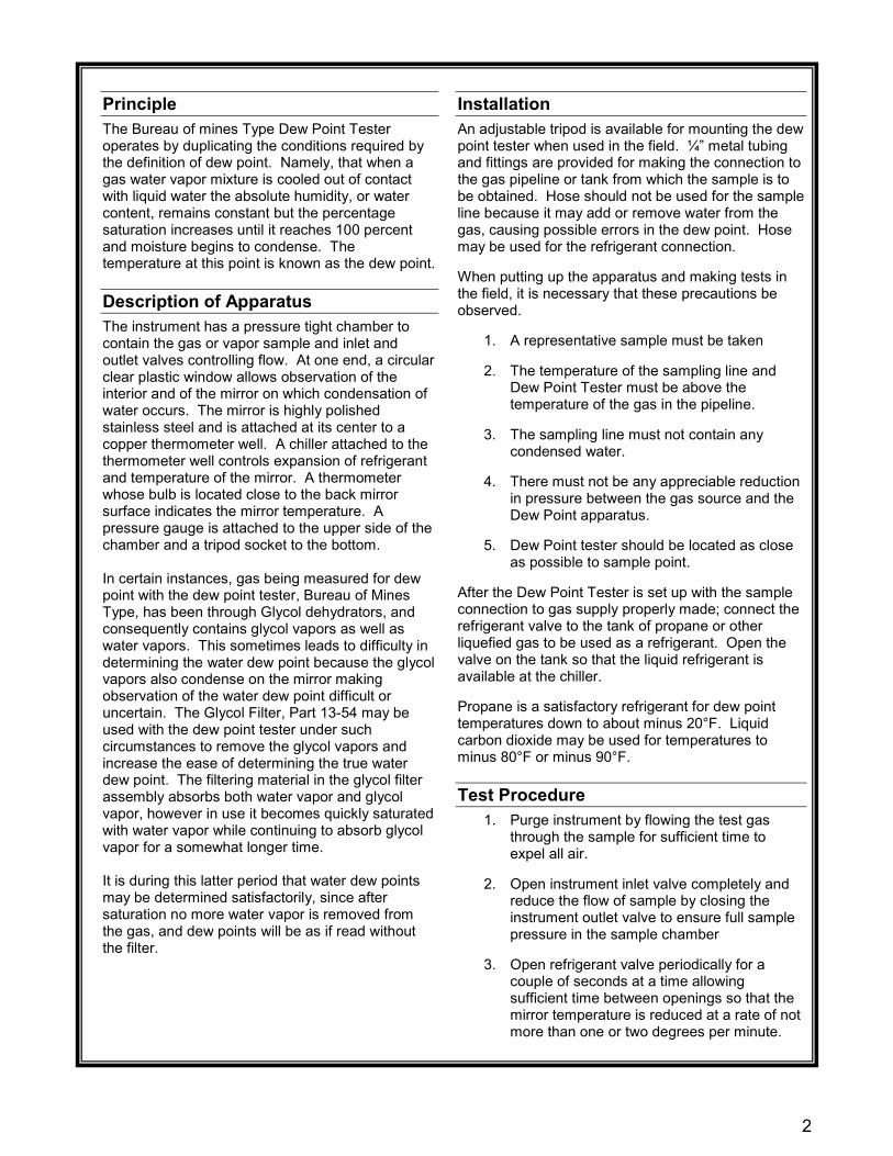
Principle The Bureau of mines Type Dew Point Tester operates by duplicating the conditions required by the definition of dew point. Namely, that when a gas water vapor mixture is cooled out of contact with liquid water the absolute humidity, or water content, remains constant but the percentage saturation increases until it reaches 100 percent and moisture begins to condense. The temperature at this point is known as the dew point.
Description of Apparatus The instrument has a pressure tight chamber to contain the gas or vapor sample and inlet and outlet valves controlling flow. At one end, a circular clear plastic window allows observation of the interior and of the mirror on which condensation of water occurs. The mirror is highly polished stainless steel and is attached at its center to a copper thermometer well. A chiller attached to the thermometer well controls expansion of refrigerant and temperature of the mirror. A thermometer whose bulb is located close to the back mirror surface indicates the mirror temperature. A pressure gauge is attached to the upper side of the chamber and a tripod socket to the bottom. In certain instances, gas being measured for dew point with the dew point tester, Bureau of Mines Type, has been through Glycol dehydrators, and consequently contains glycol vapors as well as water vapors. This sometimes leads to difficulty in determining the water dew point because the glycol vapors also condense on the mirror making observation of the water dew point difficult or uncertain. The Glycol Filter, Part 13-54 may be used with the dew point tester under such circumstances to remove the glycol vapors and increase the ease of determining the true water dew point. The filtering material in the glycol filter assembly absorbs both water vapor and glycol vapor, however in use it becomes quickly saturated with water vapor while continuing to absorb glycol vapor for a somewhat longer time. It is during this latter period that water dew points may be determined satisfactorily, since after saturation no more water vapor is removed from the gas, and dew points will be as if read without the filter.
Installation An adjustable tripod is available for mounting the dew point tester when used in the field. ¼” metal tubing and fittings are provided for making the connection to the gas pipeline or tank from which the sample is to be obtained. Hose should not be used for the sample line because it may add or remove water from the gas, causing possible errors in the dew point. Hose may be used for the refrigerant connection. When putting up the apparatus and making tests in the field, it is necessary that these precautions be observed.
1. A representative sample must be taken
2. The temperature of the sampling line and Dew Point Tester must be above the temperature of the gas in the pipeline.
3. The sampling line must not contain any
condensed water.
4. There must not be any appreciable reduction in pressure between the gas source and the Dew Point apparatus.
5. Dew Point tester should be located as close
as possible to sample point. After the Dew Point Tester is set up with the sample connection to gas supply properly made; connect the refrigerant valve to the tank of propane or other liquefied gas to be used as a refrigerant. Open the valve on the tank so that the liquid refrigerant is available at the chiller. Propane is a satisfactory refrigerant for dew point temperatures down to about minus 20°F. Liquid carbon dioxide may be used for temperatures to minus 80°F or minus 90°F.
Test Procedure 1. Purge instrument by flowing the test gas
through the sample for sufficient time to expel all air.
2. Open instrument inlet valve completely and
reduce the flow of sample by closing the instrument outlet valve to ensure full sample pressure in the sample chamber
3. Open refrigerant valve periodically for a
couple of seconds at a time allowing sufficient time between openings so that the mirror temperature is reduced at a rate of not more than one or two degrees per minute.

3
Test Procedure Continued, 4. Simultaneously observe mirror and
thermometer, noting temperature at which a spot of moisture first appears in the center of stainless steel mirror.
5. Allow mirror to warm up, noting temperature
at which moisture spot disappears.
6. Repeat 4 and 5 temperatures observed are within 2°F for appearance and disappearance of moisture spot.
7. Record the mean temperature observed as
the “Dew Point.”
Interpretation of Results Dew points may be converted to water content by use of various published curves. The Deaton and Frost Curve is attached as part of these instructions. Commercial propane is usually considered “dry” if the dew point is minus 15°F or below. Precautions Maximum working pressure of model No. 35200 Model A-2 is 3000 psi at normal temperature. This pressure should not be exceeded. Both window and mirror may be easily removed for cleaning but care should be taken to avoid scratches. Viewing the dew point mirror through the observation mirror is not only convenient but is a safety precaution in case of window failure. Sometimes it may be necessary to run a test when atmospheric temperature is below the dew point of the gas in the pipeline. It will then be necessary to apply external heat to the sample line to avoid condensation between the pipeline and dew point apparatus. The heat should be applied as close to line as possible. In testing some gasses, it may be found that the “natural gasoline” dew point of the gas will be the same, or a higher temperature than the water dew point of the gas. It is necessary to visually differentiate between the two dew points. The gasoline wets the mirror and the film expands in an iridescent ring to cover the entire mirror surface, while the water condensate remains concentrated at the center.
Use of the Glycol Filter The filter pressure chamber is installed on the inlet of the dew point tester. The pressure chamber has an easily removable end closure through which is inserted a copper tube containing the filter material. Internal dimensions are such that the sample gas, when introduced at the side of the pressure chamber is forced to flow through the filtering material before entering the dew point tester. At normal rates of flow, no pressure drop is introduced by the filter. As shown by the drawings, the installation of the glycol filter is made by removing the dew point tester inlet valve, screwing the filter into the opening from which the valve was removed, and relocating the inlet valve at the other side of the filter. In this position, the filter will not interfere with the dew point tester fitting on the tripod or in the carrying case. The copper tubing containing the filtering material is then inserted into the filter chamber and the end closed by the cap. An “O-ring” sealing gasket is used and, consequently, the cap need only be screwed up hand tight. Operation of the dew point tester with the filter attached will be normal, except that a brief period of time should be allowed for the filtering material to attain equilibrium with the sample of gas. The length of this period will be determined by the quantity of water and glycol vapor in the sample gas, and may be found running dew points. Two consecutive dew points which check and which have no glycol vapor masking the mirror indicate satisfactory operation. The filtering material in the copper tube will eventually become saturated with glycol vapor and will no longer remove the vapor from the gas, after which it must be discarded and replaced with the new filter material. Again, the length of time that one charge of filter material will perform satisfactorily depends upon the glycol vapor content of the sample gas. It is important to keep the charge of the filtering, material small rather than to increase it in attempting to give it longer life as a larger volume of filter material will require proportionately longer times to come to equilibrium and give true dew points.

4
Consumables in Natural Gas The bureau of mines dew point tester is useful for determining water content or hydrocarbon dew point in natural and processed gas. Two major advantages are:
1. It can be operated at actual line pressure up to 3000 PSI without any mathematical corrections.
2. It is a primary instrument and does not rely on electronic circuits or mechanical cells, which need to be recalibrated or decontaminated.
3. The bureau of mines dew point tester uses the human eye to distinguish between the many possible condensables in field conditions. The actual photos below represent a few of these conditions and may be used as a guide to recognize the differences in appearance as the gas falls out on a chilled mirror using a CVS Controls dew point tester.
Moisture Dew Point
Clean Mirror Appears dark, smooth, and shiny
Moisture Dew Point Dew forms a distinct opaque, grey spot approximately ¼-inch diameter directly in the center of mirror. Note the clean sharp edges at this point.
ICE Point Crystals form an irregular pattern. They appear white against the gray dew point which has enlarged across the entire mirror.
Advanced ICE Point Crystals have joined together forming a very irregular pattern.
Hydrocarbon Dew Point
Iridescent Colorful ring starts in center and expands quickly over entire mirror.
Hydrocarbon Dew Point As hydrocarbons condense, droplets begin to form.
Hydrocarbon II As temperature continues to fall, droplets join together and run across mirror.
Advanced Hydrocarbon Droplets collect into large drops which run down mirror. Eventually they freeze and turn white.
(Using Gasoline)

5
Hydrocarbon Dew Point (Using Propane)
Hydrocarbon Dew Point A fog spreads across entire mirror with dark spot in center where hydrocarbons
d
Hydrocarbon II Dark spot enlarges and starts to become irregular shape.
Hydrocarbon III As temperature drops hydrocarbons begin to run down mirror.
Advanced Hydrocarbon With little surface tension, sheets of hydrocarbons stream down mirror and begin to puddle at bottom.
Miscellaneous Dew Points
Alcohol Dew Point A white spot in the center of the mirror but has distinct edges unlike the sharp edges of the grey opaque water dew point.
Alcohol II Spot becomes larger and increasingly white with a blue tint around outside
Advanced Alcohol Entire mirror becomes very white until droplets form. The drops get larger but continue to cling to mirror without freezing.
Glycol Dew Point A light haze covers the entire mirror without beginning in middle. It does not change and will not evaporate.
6
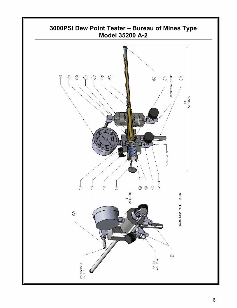
3000PSI Dew Point Tester – Bureau of Mines Type Model 35200 A-2

7
3000PSI Dew Point Tester – Bureau of Mines Type Model 35200 A-2
PART NUMBER DESCRIPTION 13-100A Dew Point Test Tank 13-100B Hose Assembly, c/w Re-Fill Adapter 35214 Tripod 13-1001 Refill Adapter Assembly 13-54* Glycol Filter, *Sold as a Complete Unit
Accessories
Item Part Number Description Item Part
Number Description
1 114V O-Ring, (2 req’d) 12 13-18 Regular Chiller Body
2 13-101 Body 13 13-20 Thermoguard Assembly
3 13-5 Lucite Window 14 13-25 Thermometer, -30 to
1100F
13-60 Thermometer, -35 to 500C
4 13-102 Observation Mirror 15 13-23 Adjusting Knob
5 13-6 Window Ret, Nut 16 13-9A Mirror insulating Ring
6 13-7 Regular Chiller Mirror 17 13-86 Carrying Case Stand
Post
7 56-21 Inlet and Outlet Valve 18 P182-WP Hose Barb
8 25S14BM-3000
2.5” Safety Gauge, HP 19 13-87* Case Bracket Knob
9 13-78 Mirror Ret. Nut 20 35200-CS* Case Assembly
10 13-9B Mirror Insulating Sleeve
11 P182-WPE Hose Elbow * Item Not Shown
Parts List

8
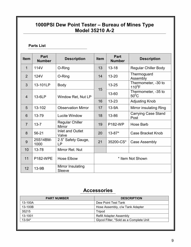
1000PSI Dew Point Tester – Bureau of Mines Type
Model 35210 A-2
9
1000PSI Dew Point Tester – Bureau of Mines Type
Model 35210 A-2
Parts List
Item Part Number Description Item Part
Number Description
1 114V O-Ring 13 13-18 Regular Chiller Body
2 124V O-Ring 14 13-20 Thermoguard Assembly
3 13-101LP Body 15
13-25 Thermometer, -30 to 1100F
4 13-6LP Window Ret, Nut LP 13-60 Thermometer, -35 to
500C 16 13-23 Adjusting Knob
5 13-102 Observation Mirror 17 13-9A Mirror insulating Ring
6 13-79 Lucite Window 18 13-86 Carrying Case Stand Post
7 13-7 Regular Chiller Mirror 19 P182-WP Hose Barb
8 56-21 Inlet and Outlet Valve 20 13-87* Case Bracket Knob
9 25S14BM-1000
2.5” Safety Gauge, LP 21 35200-CS* Case Assembly
10 13-78 Mirror Ret. Nut
11 P182-WPE Hose Elbow * Item Not Shown
12 13-9B Mirror Insulating Sleeve
PART NUMBER DESCRIPTION 13-100A Dew Point Test Tank 13-100B Hose Assembly, c/w Tank Adapter 35215 Tripod 13-1001 Refill Adapter Assembly 13-54* Glycol Filter, *Sold as a Complete Unit
Accessories

10

11

12
Rev 3, June 2010 Printed in Canada
Head Office 3900 – 101 Street
Edmonton, Alberta, Canada T6E 0A5 Office: (780) 437-3055 Fax: (780) 436-5461
Website: www.cvs-controls.com E-Mail: [email protected]
Calgary Sales Office 205, 2323 – 32 Avenue NE
Calgary, Alberta, Canada T2E 6Z3 Office: (403) 250-1416 Fax: (403) 291-9487
CVS Controls Ltd. strives for the highest levels of quality and accuracy. The information included in this publication is presented for informational purposes only. CVS Controls Ltd. reserves the right to modify or change, and improve design, process, and specifications without written notice. Under no circumstance is the information contained to be interpreted to be a guarantee/warranty with regard to our products or services, applicability or use. Selection, use and maintenance are the sole responsibility of the end user and purchaser. CVS Controls assumes no liability for the selection use and maintenance of any product.