Embed Size (px)
Citation preview
i
A! Aalto University School of Electrical Engineering
Department of Communications and Networking
Device-to-device communications for 5G Radio Access Networks
Pirkko Wahlström
Master’s Thesis submitted in partial fulfilment of the requirements for the Degree of Master of Science in Technology
Espoo, 19th of April, 2015
Supervisor: Professor Olav Tirkkonen
Instructor: Professor Olav Tirkkonen

ii
Aalto University Abstract of the Master’s Thesis
Author: Pirkko Wahlström
Title: Device-to-device communications for 5G Radio Access Networks
Date: 19th of April, 2015 Number of pages: 15+82
Faculty: Electronics, Communications and Automation
Professorship: S-72 Communications Engineering
Supervisor: Professor Olav Tirkkonen
Instructor: Professor Olav Tirkkonen
Nowadays it is very popular to share video clips and images to one’s social network in the proximity. Direct device-to-device (D2D) communication is one of the means to respond to this requirement. D2D offers users improved end-to-end latency times, and additionally can provide higher data rates. At the same time the overall cellular network congestion decreases. D2D is also known as Proximity Services (ProSe).
LTE is missing direct D2D communication. Currently D2D for 5G is standardised in the 3rd Generation Partnership Project (3GPP) Releases 12, and in parallel Mobile and wireless communications Enablers for the Twenty-twenty Information Society (METIS) project has D2D as one of its research topics. Multiple articles have been published about D2D communication.
This thesis is a literature based thesis following D2D communication in 5G literature. The scope is to describe similarities and differences found in Technical Reports and Technical Specifications of the 3GPP Release 12, in deliverables written in METIS project and in some selected D2D related publications about D2D communications.
3GPP Release 12 concentrates on ProSe at least for public safety. ProSe communication out-of-coverage is only for public safety purposes. METIS provides multiple solutions for diverse D2D topics, for example, device discovery, radio resource management, mobility management and relaying. METIS provides solutions for D2D communication not yet mature enough for development and implementation but which might be realized in the future.
Keywords: Device-to-Device, D2D, device discovery, mode selection,
Proximity Services, ProSe, Public Safety, PS

Device-to-device communications for 5G Radio Access Networks
iii
Aalto-yliopisto Diplomityön tiivistelmä
Tekijä: Pirkko Wahlström
Työn nimi: Device-to-device communications for 5G Radio Access Networks
Päiväys: 19.04.2015 Sivumäärä: 15+82
Tiedekunta: Elektroniikan, tietoliikenteen ja automaation tiedekunta
Professuuri: S-72 Tietoliikennetekniikka
Työn valvoja: Professori Olav Tirkkonen
Työn ohjaaja: Professori Olav Tirkkonen
Tiivistelmä
Nykyisin on suosittua lähettää lyhyitä videoita tai kuvia läheisyydessä oleville ystäville. Laitteiden välinen suora kommunikointi eli D2D-viestintä tuo ratkaisun tähän vaatimukseen. D2D-viestinnän ansiosta viive lyhenee ja lisäksi siirtonopeudet kasvavat. Samaan aikaan koko verkon kuormitus vähenee.
Suora kahden laitteen välinen kommunikointi puuttuu LTE:stä. Tällä hetkellä 3GPP Release 12 standardisoi suoraa kahden laitteen välistä kommunikointia. Samanaikaisesti Mobile and wireless communications Enablers for the Twenty-twenty Information Society (METIS) –projektin yhtenä tutkimuskohteenaan on kahden laitteen välinen suora kommunikointi, Lisäksi on lukuisia julkaisuja liittyen D2D-viestintään.
Tämä diplomityö perustuu kirjallisuuteen. Sen tavoitteena on selvittää, miten kahden laitteen välistä suoraa kommunikointia on kuvattu 3GPP Release 12:ta teknisissä spesifikaatioissa, METIS-projektin julkaisuissa sekä muutamassa valitussa tieteellisessä julkaisussa. Tavoitteena on selvittää D2D-viestinnän yhtäläisyyksiä sekä poikkeamia.
3PGG Release 12 standardointi keskittyy D2D-viestinnän käyttöön ainakin julkisessa pelastustyössä. D2D-viestinnän tulee ainakin julkisessa pelastustyössä toimia myös siellä missä matkapuhelinverkko ei toimi tai sitä ei ole olemassa. METIS tarjoaa useita ratkaisuja D2D-viestinnän eri osa-alueille, esimerkiksi laitteiden tunnistamiseen, resurssien hallintaan, liikkuvuuden hallintaa ja viestien edelleen lähettämiseen. METIS-projekti on tuottanut D2D-viestinnän ratkaisuja, joiden toteuttaminen on järkevää ja mahdollista vasta tulevaisuudessa.
Avainsanat:
Kieli: Englanti
iv
ACKNOWLEDGEMENTS
Thanks to Professor Olav Tirkkonen for suggesting me such an interesting
and burning topic for my thesis. Additional thanks for valuable feedback when
writing the thesis.
I would like to thank my suns, Erik (Master’s Thesis at Aalto University in year
2011) and Henrik (Master’s Thesis at Åbo Akademi University in year 2014)
for supporting in practical study related issues and encouraging during my
studies.
And last but not least, my husband Folke (Master’s Thesis at Tampere
Technical High School years ago). I have studied and worked in parallel. Due
to my full time work I have not attended any lectures, only mandatory
laboratory works. He has been most patient and encouraging, and enabled
my studying by supporting in everyday tasks.
Pirkko Wahlström
19th April, 2015

v
TABLE OF CONTENTS
ACKNOWLEDGEMENTS ....................................................................................................IV
TABLE OF CONTENTS ......................................................................................................... V
LIST OF FIGURES .............................................................................................................. VII
LIST OF TABLES ..................................................................................................................IX
LIST OF ABBREVIATIONS .................................................................................................. X
1 INTRODUCTION .......................................................................................................... 15
1.1 MOTIVATION .................................................................................................15
1.2 SCOPE .........................................................................................................16
1.3 PURPOSE .....................................................................................................16
1.4 STRUCTURE OF THE THESIS ..........................................................................16
2 DEVICE-TO-DEVICE COMMUNICATION ............................................................... 18
2.1 D2D COMMUNICATION ASPECTS .....................................................................18
2.2 D2D FOR PUBLIC SAFETY ..............................................................................20
3 CURRENT STANDARDS FOR DIRECT COMMUNICATION ............................. 22
3.1 STANDARDS FOR WIRELESS COMMUNICATION .................................................22
3.1.1 WPAN ................................................................................................................... 22
3.1.2 WLAN .................................................................................................................... 23
3.1.3 Mobile Ad Hoc networks ....................................................................................... 25
3.1.4 Cognitive Radio..................................................................................................... 25
3.2 STANDARDS FOR PUBLIC SAFETY ....................................................................25
3.2.1 TETRA .................................................................................................................. 26
3.2.2 P25 ........................................................................................................................ 28
4 3GPP RELEASE 12 FOR PROXIMITY SERVICES .............................................. 30
4.1 3GPP RELEASE 12 FOR PROSE .....................................................................30
4.2 PROSE FOR PUBLIC SAFETY AND PROSE SERVICES ........................................32
4.2.1 Public Safety use cases ........................................................................................ 32
4.2.2 Direct Communication Scenarios ......................................................................... 33
4.2.3 Control modes for D2D scenarios......................................................................... 37
4.3 ARCHITECTURAL ENHANCEMENTS FOR PROSE ................................................40
4.3.1 Reference architectural model .............................................................................. 40
4.3.2 EPC-level ProSe Discovery .................................................................................. 43
4.3.3 EPC Support for WLAN direct discovery and Communication ............................. 45
4.3.4 Direct Discovery .................................................................................................... 45
4.3.5 Direct Communication .......................................................................................... 47
4.3.6 UE-to-Network Relay ............................................................................................ 48
4.3.7 Synchronization .................................................................................................... 49
5 METIS APPROACH TO D2D COMMUNICATION ................................................. 50
5.1 OVERVIEW OF METIS ....................................................................................50
5.2 WP1: SCENARIOS, REQUIREMENTS AND KPIS APPROACH TO D2D
COMMUNICATION ........................................................................................................53
5.3 WP2: RADIO LINK CONCEPTS APPROACH TO D2D COMMUNICATION .................54
5.3.1 T2.1 Air Interface Design ...................................................................................... 55

Device-to-device communications for 5G Radio Access Networks
vi
5.3.2 T2.2 Waveform, Modulation and Coding, and TRX .............................................. 55
5.3.3 T2.3 Multiple Access, MAC and RRM .................................................................. 56
5.4 WP3: MULTI-NODE / MULTI-ANTENNA TRANSMISSION APPROACH TO D2D
COMMUNICATION .........................................................................................................57
5.4.1 WP3 T3.1 Multi-antenna/Massive-MIMO and T3.2 Advanced inter-node coordination .......................................................................................................... 57
5.4.2 WP3 T3.3 Multi-hop communication/wireless network coding ............................. 58
5.5 WP4: MULTI-RAT/MULTI-LAYER NETWORKS APPROACH TO D2D
COMMUNICATION .........................................................................................................58
5.5.1 T4.1 Co-existence, Collaboration and Interference Management ........................ 61
5.5.2 T4.2 Demand, Traffic and Mobility Management .................................................. 61
5.5.3 T4.3 Functional Management ............................................................................... 62
5.6 WP5: SPECTRUM APPROACH TO D2D COMMUNICATION ..................................62
5.6.1 Frequency Band Analysis ..................................................................................... 63
5.6.2 Flexible Spectrum Access .................................................................................... 64
5.7 WP6: HT D2D CONCEPT AND SYSTEM DESIGN ...............................................64
5.7.1 HT D2D concept ................................................................................................... 66
5.7.2 Flexible TDD air interface for D2D ........................................................................ 67
5.7.3 D2D device discovery and Communication mode selection ................................ 68
5.7.4 Interference management ..................................................................................... 71
5.7.5 Resource allocation .............................................................................................. 72
5.7.6 Power control ........................................................................................................ 75
5.7.7 D2D relay and relayed D2D .................................................................................. 75
5.7.8 Mobility management ............................................................................................ 78
5.7.9 Spectrum detection, management and sharing .................................................... 79
5.7.10 Other: Backhaul .................................................................................................... 79
5.7.11 D2D in Intermediate system concept and System Architehture ........................... 80
6 RESULTS ...................................................................................................................... 83
7 CONCLUSIONS ........................................................................................................... 86
REFERENCE .......................................................................................................................... 87
A TECHNOLOGY COMPONENTS IN WP2 ..................................................................... 90
B TECHNOLOGY COMPONENTS IN WP3 ...................................................................... 92
C TECHNOLOGY COMPONENTS IN WP4 ..................................................................... 94
D TECHNOLOGY COMPONENTS IN WP5 ..................................................................... 96
vii
LIST OF FIGURES
Figure 1. D2D communication as an underlay network to an infrastructure network [5] ......... 18
Figure 2. Network and relay control modes [6] ....................................................................... 19
Figure 3. Direct D2D communication scenarios based on spectrum and network assistance [8] .............................................................................................................................................. 20
Figure 4. An example of group communication in public safety [7] ......................................... 21
Figure 5. IEEE 802.11 LAN architecture [9] ............................................................................. 24
Figure 6. TERTA network interfaces [18] ................................................................................. 26
Figure 7. Different TETRA direct modes [19] ........................................................................... 28
Figure 8. Spectrum allocated for public safety in P25 [20] ....................................................... 29
Figure 9. An overview of D2D communication [6] .................................................................... 31
Figure 10. UEs are out-of-coverage (scenario 1A) [23] ........................................................... 34
Figure 11. UEs with partial coverage (scenario 1B) [23] .......................................................... 34
Figure 12. Both UEs are in coverage of one cell (scenario 1C) [23] ........................................ 34
Figure 13. Both UEs are in-coverage of multiple cells (scenario 1D) [23] ............................... 34
Figure 14. UEs are in different cells and PLMNs (scenario 1E) [23] ....................................... 35
Figure 15. UEs are in different PLMNs and one UE is in common cell coverage (scenario 1F) [23] ............................................................................................................................................ 35
Figure 16. UEs are in different cells and different PLMNs (scenario 1G) [23] ......................... 35
Figure 17. Relaying [8] ............................................................................................................. 36
Figure 18. UE-Relay variants. [R12-8] [23] .............................................................................. 36
Figure 19. Default data path between two UEs in current specification [28] ........................... 37
Figure 20. Communication between two UEs using Direct Mode data path [28] .................... 38
Figure 21. The data path for two UEs served by the same eNB [28] ...................................... 38
Figure 22. An example of control path for network-supported ProSe communication when the UEs are served by the same eNB [28] ..................................................................................... 38
Figure 23. An example of control path for network supported ProSe communication where the UEs are served by different eNBs [28] ..................................................................................... 39
Figure 24. An example of control path for public safety cases when no network support [28] 39
Figure 25. Control modes for different D2D scenarios [6] ........................................................ 40
Figure 26. ProSe non-roaming reference architecture model [29] ........................................... 41
Figure 27. ProSe Function Interfaces to other network elements and PLMNs [23] ................ 43
Figure 28. UE to ProSe Function Interfaces for each sub-function [23] .................................. 43
Figure 29. Architectural reference model for direct discovery (non-roaming) [23], [29] ........... 44
Figure 30. Architecture for EPC-level discovery using C-plane location services [23] ............ 44
Figure 31. Architecture for EPC-level discovery using U-plane location services [23] ............ 45
Figure 32. Announcing and monitoring UE roles in different PLMNs [23] ............................... 46
Figure 33. ProSe direct discovery procedure [23] .................................................................... 46
Figure 34. ProSe UE-to-Network Relay [29] ............................................................................ 49
Figure 35. System Integration: HTs and TeCs [4] .................................................................... 53
Figure 36. D2D communication use cases [40] ....................................................................... 53
Figure 37. The air Interface [44] ............................................................................................... 55
Figure 38. LTE heterogeneous network nodes and their interfaces [45] ................................. 57
Figure 39. Functionalities for supporting underlay of D2D communication [46] ...................... 59
Figure 40. Heterogeneous multi-layer and multi-RAT deployments [44] ................................. 59

Device-to-device communications for 5G Radio Access Networks
viii
Figure 41. The Phantom Cell system concept [46] .................................................................. 60
Figure 42. The initial high level proposal for HT D2D concept [39].......................................... 67
Figure 43. System model for Device discovery [46] ................................................................. 69
Figure 44. System model Distributed CSI mode selection for D2D [46] .................................. 70
Figure 45. Location based mode selection [46] ....................................................................... 70
Figure 46. System model for Decentralized interference aware scheduling [51] ..................... 71
Figure 47. Signaling scheme for D2D communication with full CSI [43] .................................. 72
Figure 48. Signaling scheme for D2D communication with partial CSI [43] ............................ 73
Figure 49. System model for Further enhanced ICIC for enabling D2D in heterogeneous networks [46] ............................................................................................................................ 74
Figure 50. System model for Interference aware routing and resource allocation for access and backhaul TeC2 [51] ........................................................................................................... 74
Figure 51. System model for Distributed Coding for Multiple Access Multiple Relay Channel [51] ............................................................................................................................................ 76
Figure 52. System model for Bi-directional relaying with non-orthogonal multiple access [51] .................................................................................................................................................. 76
Figure 53. System model Underlay D2D communication with PHY layer network coding TeC6 [51] ............................................................................................................................................ 77
Figure 54. System model for Closed-loop and open-loop techniques in a network with D2D relaying [51] .............................................................................................................................. 77
Figure 55. System model for Cooperative D2D Communications [51] .................................... 78
Figure 56. System model for Distributed Precoding in multicell multiantenna systems with data sharing [51] ....................................................................................................................... 79
Figure 57. HT D2D combined into a set of fundamental services............................................ 81
Figure 58. HT D2D and the main BBs ...................................................................................... 82
ix
LIST OF TABLES
Table 1. Features of IEEE 802.15 standards ........................................................................... 23
Table 2. Main WLAN standards ............................................................................................... 24
Table 3. ProSe WIs in 3GPP Release 12 ................................................................................ 31
Table. 4 In-coverage and out-of-coverage scenarios for ProSe .............................................. 33
Table 5. ProSe direct communication scenarios ...................................................................... 33
Table 6. Reference Points in non-roaming reference architecture model ............................... 41
Table 7. METIS overall goals supported by HT D2D ............................................................... 54
Table 8. Bandwidth in D2D supported TCs .............................................................................. 63
Table 9. TeCs selected in D6.2 [39] and D6.3 [36] ................................................................. 65

x
LIST OF ABBREVIATIONS
3GPP 3rd Generation Partnership Program
5G 5th Generation
AN Access Node
AP Access Point
AS Application Server
AZ Access Zone
BB Building Block
BBU Backup Battery Unit
BS Base Station
BSS Basic Service Set
CDMA Code Division Multiple Access
CEPT Conference of European Post and Telephone Administrations
CEPT ECA European Table of Frequency Allocations
CH Cluster Head
CNMI Central Network Management Interface
CN Core Networks
CoMP Coordinated Multipoint
C-plane Control plane
CR Cognitive Radio
CSG Closed Subscriber Group
CSI Channel State Information
CSMA Carrier Sense Multiple Access
CUE Cellular UE
D2D Device-to-Device
D2DSS D2D Synchronization Signal
DL Down link
DMO Direct Mode Operation
DeND Donor NB
DPF Direct Provisioning Function
DSL Digital Subscriber Line
eNB Evolved Node B
Device-to-device communications for 5G Radio Access Networks
xi
EPC Evolved Packet Core
ETSI European Telecommunications Standards Institute
E-UTRA Evolved UTRA
E-UTRAN Evolved-UMTS Terrestrial Radio Access Network
FBMC Filter-bank based multi-carrier
FCC Federal Communications Commission
FDMA Frequency Division Multiple Access
FH Frequency Hopping
G Giga
GPRS General Packet Radio Service
HARQ Hybrid Automatic Repeat Request
HetNet Heterogeneous Network
HiperLAN HIgh PErformance Radio LAN
HPLMN Home Public Land Mobile Network
HSPA High Speed Packet Access
HSS Home Subscriber Server
HT Horizontal Topic
Hz Herz
ICIC Inter Cell Interference Coordination
ID Identity
IDMA Interleave Division Multiple Access
IEEE Electrical and Electronics Engineering
IP Internet Protocol
IRC Interference Rejection Combining
ISDN Integrated Services Digital Network
ISI Inter System Interface
ISM Industrial, Scientific and Medical
ITU-R International Telecommunications Union- Radiocommunication Sector
kb/s Kilo bits per second
KPI Key Performance Indicator
LAN Local Area Network
LTE Long Term Evolution
LTE-A LTE Advanced
m Meter
Device-to-device communications for 5G Radio Access Networks
xii
M Mega
M2M Machine-to-Machine
MA Multiple Access
MAC Medium Access Control
MANET Mobile Ad Hoc Network
MBB Mobile Broadband
MBMS Multimedia Broadcast/Multicast Service
METIS Mobile and Wireless Communications Enablers for the 2020 Information Society
MIMO Multiple Input Multiple Output
MMC Massive Machine Communication
MME Mobility Management Entity
MMSE Minimum Mean Square Error
MN Moving Networks
MNO Mobile Network Operator
NRA National Regulatory Authority
OFDM Orthogonal Frequency Division Multiple
OFDMA Orthogonal Frequency Division Multiple Access
OMA Orthogonal Multiple Access
P25 Project P25
PAMR Private Access Mobile Radio
PC Personal Computer
PCC Phantom Cell Concept
PDA Personal Digital Assistant
PDCCH Physical Download Control Chanel
PDN Packet Data Network
PEI Peripheral Equipment Interface
PGW Paging Gateway
PHY Physical
PLMN Public Land Mobile Network
PMR Private Mobile Radio
PON Passive Optical Network
PRB Power Resource Block
ProSe Proximity Services
PS Public Safety

Device-to-device communications for 5G Radio Access Networks
xiii
PSS Primary Synchronization Signal
PSTN Public Switching Telephone Network
QoS Quality of Services
RAN Radio Access Network
RAT Radio Access Technology
RN Relay Node
RRM Radio Resource Management
RRU Remote Radio Unit
RSSI Received Signal Strength Indicator
Rx Receiver
SA System Architecture
SC Small Cell
SC-OFDM Single Carrier Orthogonal Frequency Division Multiple
SGW
SINR Signal to Interference and Noise Ratio
SLP SUPL Location Platform
SRD Short Range Device
SUPL Secure User Plane Location
SwMI Switching and Management Infrastructure
T Task
TC Test Case
TDD Time Division Duplex
TDMA Time Division Multiple Access
TeC Technology Component
TeCC TeC Cluster
TETRA Trans European Trunked Radio
TIA Telecommunications Industry Association
TMO Trunked Mode Operation
TR Technical Report
TS Technical Specification
Tx Transmitter
UDN Ultra Dense Networks
UE User Equipment
UFMC Universal filtered multi-carrier
UHF Ultra High Frequency

Device-to-device communications for 5G Radio Access Networks
xiv
UL Uplink
UMTS Universal Mobile Telecommunications System
U-plane User Plane
URC Ultra Reliable Communication
UTRA Universal Terrestrial Radio Access
UTRAN Universal Terrestrial Radio Access Network
UWB Ultra Wideband
V2X Vehicle-to-X
WI Work Item
WiFi Wireless Fidelity
WP Work Package
VPLMN Visitor Public Land Mobile Network
WLAN Wireless Local Area Network
WPAN Wireless Personal Area Network
Device-to-device communications for 5G Radio Access Networks
15
1 INTRODUCTION
1.1 MOTIVATION
Visions for the 5G mobile and wireless communication systems forecast growing traffic volumes and increasing number of mobile devices. Traffic volumes in wireless communication have grown during the last years, and the growth is expected to continue also in the future. Traffic volumes beyond the year 2020 can be even 1000 times higher than traffic volumes of today. Future cellular networks will become denser with small cells. Compared to traditional macro cellular systems multi-layered networks with macro-cell layer covering relays, pico-cell and femto-cell layers, is becoming one option for better coverage, capacity and spectral efficiency [1] [2].
Overall targets for 5G systems are higher throughput per area and per user, and lower latency. The 5G systems will support huge amount of devices, and with energy consumption lower compared to current systems. D2D communication is seen as one answer to growing demands for future mobile and wireless communication systems. D2D might offer higher data rates and lower latency due to the short distance between the D2D pair. D2D communication is also energy efficient as no data communication via Base Station (BS), and thus also the traffic loads of BS decreases.
D2D communication will be network controlled or not network controlled when out-of-coverage, and D2D will (re)use the same licensed spectrum as the cellular links. D2D communication takes place directly between a D2D pair without base station controlling the communication. D2D communication can also be used in areas out-of-coverage or when cellular network fails, mainly for public safety purposes.
Currently Long Term Evaluation (LTE) is missing direct device-to-device communication function. However D2D communication or ProSe is in scope of 3GPP Release 12 [3], and additionally it is included in the METIS project [4].
This thesis describes ProSe or D2D in 3GPP Release 12 and in METIS project. D2D specific requirements are, for example, device discovery, mode selection, direct communication and resource management. D2D for public safety is included as public safety will utilize D2D communication.

Device-to-device communications for 5G Radio Access Networks
16
1.2 SCOPE
As mentioned before LTE is missing direct D2D communication. Direct D2D communication will be new functionality in the 5G cellular and mobile networks. D2D is currently being standardised by 3GPP Release 12 and standardisation work continues in 3GPP Release 13, and D2D is in scope of METIS research work. The scope of the thesis is to follow in 3GPP Release 12 documentation and METIS deliverables, for example, device discovery, mode selection and direct communication for direct D2D communication. Public safety is additionally in scope as it is a scope item in 3GPP Release 12.
1.3 PURPOSE
The thesis studies D2D communication in the 5G literature, i.e. in 3GPP Release 12 Technical Reports (TR) and Technical Specifications (TS), in METIS deliverables and additionally in some scientific publications. The thesis follows D2D in 5G Radio Access Networks in 3GPP Release 12 standardization documents and in METIS deliverables. The purpose is to find out similarities and differences in D2D in the 5G literature of the 3GPP Release 12 TSs and TRs, METIS deliverables and some scientific publications.
1.4 STRUCTURE OF THE THESIS
The thesis has been structured into the following chapters that are shortly
outlined below:
Chapter 2 provides an overview of direct device-to-device communication. It describes on high level how direct communication takes place between the D2D pair.
Chapter 3 lists current standards for direct device-to-device communication. Current direct device-to-device standards are listed with limited information about their features. Standards are grouped on wireless coverage and two standards for public safety are included. The chapter includes also Mobile Ad Hoc Networks (MANET) and Cognitive Radio (CR) as they have similarities with D2D communication.
Chapter 4 includes an overview of ProSe in 3GPP Release 12. 3GPP Release 12 has Work Items (WIs) for ProSe. The chapter describes D2D communication specific topics like device discovery, scenarios, mode selection and communication. Public safety is included as well as it is in scope of 3GPP Release 12.
Chapter 5 describes the METIS approach to D2D communication. METIS Work Packages (WPs) are processed into Technology Components (TeCs), and the chapter includes TeCs enablers for Horizontal Topic (HT) D2D communication. The METIS system concept development utilizes HT specific concepts and thus also HT D2D concept has been defined. TeCs enablers for HT D2D communication are collected under the areas of the HT D2D concept. Building Block (BB) is an entity used in the METIS system architecture development. BBs are derived from the HT concepts, and three different types

Device-to-device communications for 5G Radio Access Networks
17
of BBs have been identified. The chapter lists BBs of HT D2D communication. .
Chapter 6 summarizes the status of D2D communication in 3GPP Release 12 and METIS project. Summarization follows the D2D communication specific features. 3GPP Release 12 schedule is March 2015 and METIS ends 30th April 2015.
Chapter 7 includes the conclusions of D2D communication in Technical Reports and Technical Specifications of 3GPP Release 12 and deliverables written in METIS project.
Device-to-device communications for 5G Radio Access Networks
18
2 DEVICE-TO-DEVICE COMMUNICATION
This chapter describe features specific for the direct D2D communication. Both in 3GPP Release 12 and in METIS project D2D communication specifications bases on LTE technology.
2.1 D2D COMMUNICATION ASPECTS
D2D communication is the communication between two UE devices in proximity using an LTE air interface to set up a direct link without routing via Evolved Node B (eNB) and possibly Core Network (CN). Proximity should be understood also for example as channel conditions, Signal-to-Interference-and-Noise Ratio (SINR), throughput, delay and load, and not only the distance between the D2D pair.
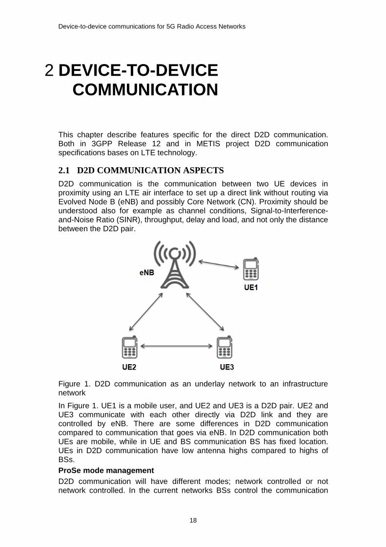
Figure 1. D2D communication as an underlay network to an infrastructure network
In Figure 1. UE1 is a mobile user, and UE2 and UE3 is a D2D pair. UE2 and UE3 communicate with each other directly via D2D link and they are controlled by eNB. There are some differences in D2D communication compared to communication that goes via eNB. In D2D communication both UEs are mobile, while in UE and BS communication BS has fixed location. UEs in D2D communication have low antenna highs compared to highs of BSs.
ProSe mode management
D2D communication will have different modes; network controlled or not network controlled. In the current networks BSs control the communication

Device-to-device communications for 5G Radio Access Networks
19
between two UEs. In the D2D communication BSs do not have any more the overall control, but the control is at some extent moved to UEs. This is a change also to the Mobile Network Operators (MNOs) as they have the control over the network.
Network control or infrastructure-based control means that the network services (e.g. synchronization, session setup, resource allocation and routing) are provided by the network to which the host is connected to via a BS. This means that the network controls the communication between the devices in D2D communication. Figure 2. shows network and relay control modes.
Figure 2. Network and relay control modes [5]
No network control or infrastructure-less control means that no network services provided, and the hosts themselves must provide services like routing. This means that D2D communication has ad hoc or Cluster Head (CH) type of control. Ad hoc networks are multi-hop and infrastructure-less networks without bases stations. Nodes may have to relay messages via multiple nodes for reaching the destination.
As mentioned before, D2D communication will base on LTE technology, and D2D UEs will share the same radio resources with the cellular UEs. This is something different from the current resource use. Unlicensed Industrial, Scientific and Medical (ISM) band is used in communication within Wireless Personal Area Network (WPAN) and Wireless Local Area Network (WLAN). In addition public safety uses spectrum band specifically reserved for public safety.
Device Discovery
Device discovery is one of the key issues in direct D2D communication [5]. For D2D communication to take place two UEs need to discover each other.
Direct communication
After two devices have discovered each other and mode selection is done, two devices can communicate directly with each other.
D2D communication includes one-to-one, one-to-many/unicast, one-to-many/broadcast, and on-hop relay functionalities. Access priorities and session transfer from direct-based communication path to network-based one are considerations as well [6]. Different communication modes are needed when communicating in an emergency situation.
Interference management
Device-to-device communications for 5G Radio Access Networks
20
Interference management will be a challenge as interference will be generated between D2D links and cellular links. For properly managing and deciding when communication takes place directly between the UEs or via cellular network, sensing, scheduling and handling of interference is needed. In practice this means that information is needed for making the decision when D2D communication is beneficial or not.
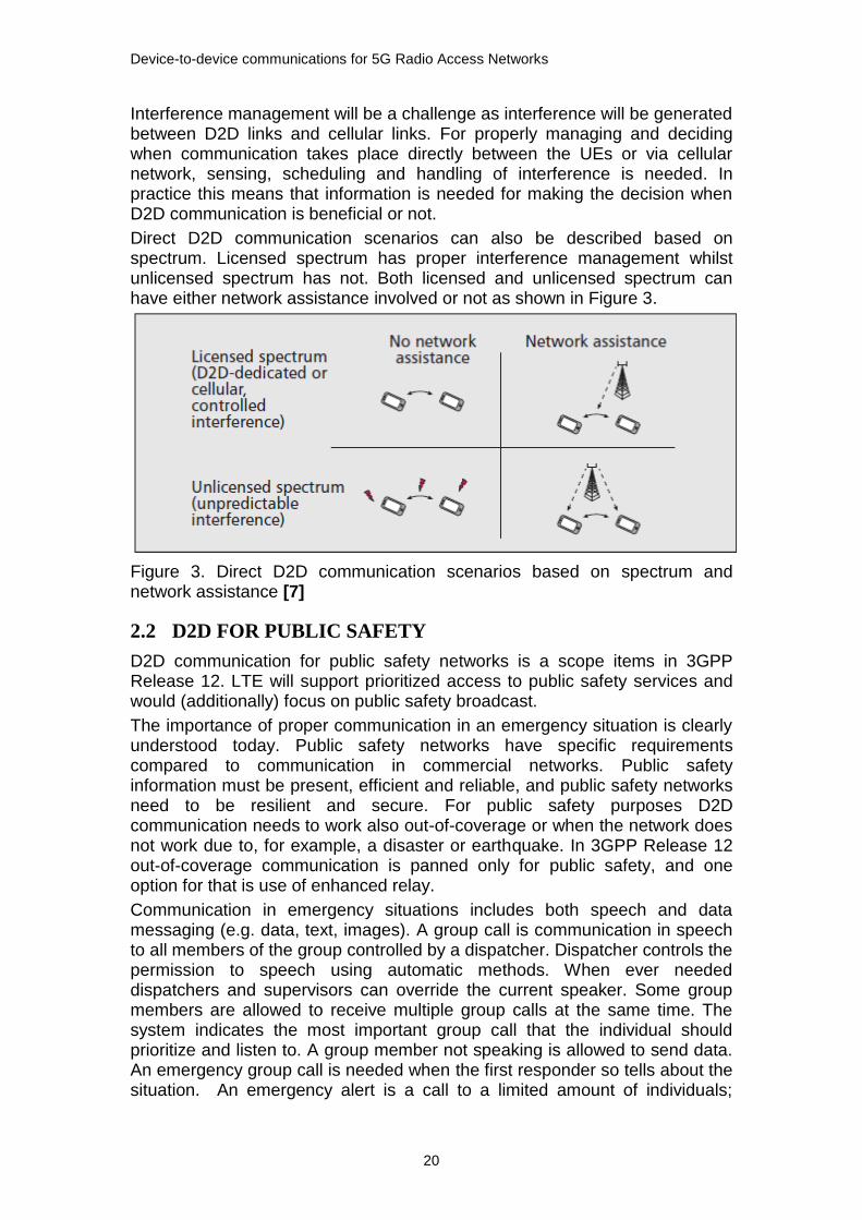
Direct D2D communication scenarios can also be described based on spectrum. Licensed spectrum has proper interference management whilst unlicensed spectrum has not. Both licensed and unlicensed spectrum can have either network assistance involved or not as shown in Figure 3.
Figure 3. Direct D2D communication scenarios based on spectrum and network assistance [7]
2.2 D2D FOR PUBLIC SAFETY
D2D communication for public safety networks is a scope items in 3GPP Release 12. LTE will support prioritized access to public safety services and would (additionally) focus on public safety broadcast.
The importance of proper communication in an emergency situation is clearly understood today. Public safety networks have specific requirements compared to communication in commercial networks. Public safety information must be present, efficient and reliable, and public safety networks need to be resilient and secure. For public safety purposes D2D communication needs to work also out-of-coverage or when the network does not work due to, for example, a disaster or earthquake. In 3GPP Release 12 out-of-coverage communication is panned only for public safety, and one option for that is use of enhanced relay.
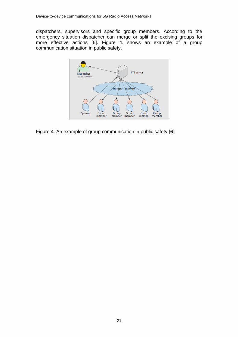
Communication in emergency situations includes both speech and data messaging (e.g. data, text, images). A group call is communication in speech to all members of the group controlled by a dispatcher. Dispatcher controls the permission to speech using automatic methods. When ever needed dispatchers and supervisors can override the current speaker. Some group members are allowed to receive multiple group calls at the same time. The system indicates the most important group call that the individual should prioritize and listen to. A group member not speaking is allowed to send data. An emergency group call is needed when the first responder so tells about the situation. An emergency alert is a call to a limited amount of individuals;
Device-to-device communications for 5G Radio Access Networks
21
dispatchers, supervisors and specific group members. According to the emergency situation dispatcher can merge or split the excising groups for more effective actions [6]. Figure 4. shows an example of a group communication situation in public safety.
Figure 4. An example of group communication in public safety [6]
Device-to-device communications for 5G Radio Access Networks
22
3 CURRENT STANDARDS FOR DIRECT COMMUNICATION
This chapter describes Institute of Electrical and Electronics Engineering (IEEE) standard families IEEE 802.15, IEEE 802.11 and IEEE 802.16, and HiperLAN/2 (HIgh PErformance Radio LAN) standard defined by the European Telecommunications Standards Institute (ETSI). HiperLAN standards are European alternative for the IEEE 802.11 standards. Additionally Mobile AdHoc networks (MANET) and Cognitive Radio (CR) are included to present alternative wireless communication optins.
3.1 STANDARDS FOR WIRELESS COMMUNICATION
Wireless standards can be divided into two following categories:
1. Wireless Personal Area Networks (WPAN)
2. Wireless Local Area Networks (WLAN)
The first category WPAN is a standard family of IEEE 802.15 standards [8]. Bluetooth works in unlicenced ISM frequency band. Standards selected for this document are:
IEEE 802.15.1, Bluetooth [9]
IEEE 802.15.4, ZigBee [10]
IEEE 802.15.3, Ultra Wide Band (UWB) [11]
The second category is WLAN standard and it is also known as WiFi IEEE 802.11 standard family [12] [8]. WLAN works in unlicenced ISM frequency band. Following standards are selected for the thesis:
IEEE 802.11a
HiperLAN/2 (ETSI) [13]
IEEE 802.11b
IEEE 802.11g
IEEE 802.11n
IEEE 802.11p
The third category WMAN is a standard family of IEEE 802.16 standards. Following standards have been selected for the thesis:
WiMAX IEEE 802.16e
WiMAX IEEE 802.16m
3.1.1 WPAN
IEEE 802.15 standard family focuses on WPAN, i.e. radio networks with a short range. Table 1. lists some of WPAN features.

Device-to-device communications for 5G Radio Access Networks
23
Table 1. Features of IEEE 802.15 standards
Standard Frequency Range Data Rate Coverage
Bluetooth, IEEE 802.15.1 2.4 MHz 1-2 Mbit/s 10 m
ZigBee, IEEE 802.15.4 2.4 GHz, 868 MHz in Europe), (915 MHz in USA)
250 kbits/s, 20 kbps
70 m
UWB, IEEE 802.15.3 3.1 GHz, 10.6 GHz Max 200 Mbits/s
10 m
Bluetooth
Bluetooth is an unlicensed spectrum technology, a technology that provides short-range radio links to allow mobile computers, mobile phones, digital cameras, and other portable devices to communicate with each other without cables. Bluetooth network is a infrastructure-less network.
Bluetooth uses a method similar to 802.11 in the ISM waveband with a quick Frequency Hopping (FH) approach. Frequency Hopping is a technique in which the instantaneous carrier frequency of a signal is, according to a predetermined code, periodically changed to other positions within a frequency spectrum that is much wider than that required for normal transmission.
Bluetooth is an example of single-hop and infrastructure-less network. It has no BS with connection to wired network. One node of the single-hop network may coordinate the communication of the other nodes.
ZigBee
IEEE 802.15.4 ZigBee is a standard for very-short-range communication between different devices. It is targeted for used in industry, households, and facility management applications for controlling and monitoring. In practise these are applications with only low levels of data throughput and low power consumption, for example sensors in lighting controls and security.
ZigBee achieves slower transfer rates than Bluetooth and 802.11, but the technology uses less power. In contrast to other WLAN protocols, ZigBee can use the UWB to transmit encoded signals over a wide spectrum.
UWB
UWB is a technology for wireless Local Area Networks (LANs) which achieves far higher transmission speeds than 802.11. UWB utilizes low transmitter (Tx) power to achieve a range of only 10 m. The purpose is a short range network to connect peripheral and consumer devices.
3.1.2 WLAN
IEEE802.11 Wireless Fidelity (WiFi) is an unlicensed spectrum technology. It works in ISM bands. Wi-Fi is a technology of wireless local area networks that operate according to the IEEE 802.11. WLAN is a technology that provides inter-operable wireless access between devices.
WLAN 802.11 is an example of single-hop and infrastructure-based networks. The networks have a BS and connection to wired network. Communication

Device-to-device communications for 5G Radio Access Networks
24
between the BS and the wireless host is single wireless hop. Table 2. lists some WLAN standards and some of their features
Establishing D2D links by IEEE WLAN standard in ISM band in order to offload the cellular network, are already implemented.
Table 2. Main WLAN standards
Standard Frequency range Data rates up to
Coverage indoor
Coverage outdoor
802.11a 5 GHz 54 Mbps 10-30 m 50m-5km
HiperLAN/2 5 GHz 54 Mbps
802.11b 2.4 GHz 11 Mbps 10-30 m 50m-5km
802.11g 2.4 GHz 54 Mbps 10-30 m 50m-5km
802.11n 2.4 GHz and 5 GHz 600 Mbps 10-30 m 50m-5km
802.11p 1) 5.9 GHz 250 kbps 2) 15-20 m 2)
1) IEEE 802.11p is for communication between vehicles or between vehicles and fixed infrastructure
2) In Europe
Figure 5. shows the 802.11 architecture with the principle components. Each Personal computer (PC) communicates with an Access Point (AP), and AP is connected via a switch or router to the Internet [8]. A Basic Service Set (BSS) composes of PCs and an AP.
Figure 5. IEEE 802.11 LAN architecture [8]
Access zone (AZ) or public AZ or hotspot or AP is a public location (for example an office, campus, hotel or airport) where wireless LAN connections are provided to users. A person with a Wi-Fi-enabled laptop or PDA (Personal Digital Assistant) can access the Internet within a Wi-Fi hotspot.
If no AP is available PCs can create an ad hoc network for communication purposes.
HiperLAN2
Device-to-device communications for 5G Radio Access Networks
25
The physical (PHY) layer of HiperLAN/2 is very similar to IEEE 802.11a wireless local area networks. However, the Medium Access Control (MAC) (the multiple access protocol) is Dynamic Time Division Multiple Access (TDMA) in HiperLAN/2, while Carrier Sense Multiple Access (CSMA)/CA is used in 802.11a.
3.1.3 MOBILE AD HOC NETWORKS
Ad hoc network does not have a base transceiver station, central control, or wired infrastructure. Ad hoc network communications are supported via mobile-to-mobile transmission. An ad hoc network is formed automatically or semi-automatically from devices that happen to be physically near each other.
Ad hoc networks can change locations and configure itself on the fly. Mobile ad hoc networks (MANETs) are mobile, they use wireless connections to connect to various networks [14]. This can be a standard Wi-Fi connection, or another medium, such as a cellular or satellite transmission. MANETs can arrange themselves in various ways and operate without strict top-down network administration.
Planned use cases for MANET networks are emergency and rescue operations, disaster relief efforts and military networks. In these cases direct device-to-device communications are in scope.
3.1.4 COGNITIVE RADIO
A Cognitive Radio is an intelligent radio that can be programmed and configured dynamically. Its transceiver is designed to use the best wireless channels in its vicinity. Such a radio automatically detects available channels in wireless spectrum, then accordingly changes its transmission or reception parameters to allow more concurrent wireless communications in a given spectrum band at one location. This process is a form of dynamic spectrum management. Cognitive Radio detects white space, sensing white space requires detecting receivers of the primary system, which is a difficult task especially for broadband systems.
3.2 STANDARDS FOR PUBLIC SAFETY
Standards for public safety networks:
Terrestrial Trunked Radio (TETRA)
Project P25 (P25)
ETSI standard TETRA is the public safety standard in Europe and P25 is the corresponding standard in United States.
The main purpose of public safety is to protect citizens and property, and save peoples’ lives. Public Safety networks have some specific requirements compared to commercial networks. Public Safety information must be present, efficient and reliable, and PS networks need to be resilient and secure. In additional there are functionality requirements like radio coverage, end-to-end performance and device characteristic.
It is understood that effective communication in emergency situations is of most importance, and interest in investing in developing public safety networks has grown. Current public safety networks bases on 2G technology, and LTE is being widely deployed in commercial networks. This means that

Device-to-device communications for 5G Radio Access Networks
26
there is a technology gap for public safety networks. However LTE is seen to be the most widely deployed broadband communication system, and should also fulfil or complement requirements of public safety networks. Safety private networks need to be safe and reliable, work even if network fails or no coverage.
TETRA supports only voice and data. However e.g. multimedia applications, pictures and videos clips are required in emergency situation management today. For example, narrowband voice services are at 9,6 kb/s and broadband video services require minimum 256 kb/s when used in suburban and rural areas.
Public safety networks to respond to demands from a public safety communication system with different roles and responsibilities, speech and data messaging, require multiple actions from under-laying radio systems. For example an emergency group call needs to go through whenever the first responder pushed her/his device for it.
3.2.1 TETRA
TETRA is an ETSI standard for public safety, security organisations, oil fields and railways. TETRA network is a digital network that was planned for authority use. The user groups and organisations of TETRA include Private Mobile Radio (PMR) and Private Access Mobile Radio (PAMR) users, and operators for such networks. CEPT/SE has defined for TETRA frequency band 380-400 MHz [15], and TETRA system supports voice and data [15]. For direct device-to-device communication TETRA system has Direct Mode Operation (DMO) functionality [16]. TETRA networks have not been deployed with enhanced data rates, so software vendors have considered hybrid solutions. TETRA is used only for critical signalling and LTE is used for large data synchronization and transfer of images and video.
TETRA standard has specified interfaces shown in Figure 6. for enabling communication in TETRA networks and commercial networks even if network equipments have different manufacturers [17].
Figure 6. TERTA network interfaces [17]
Interfaces specified by TETRA standard are:

Device-to-device communications for 5G Radio Access Networks
27
1. The air (trunking) interface between the TETRA BS and the user terminals.
2. The air interface for DMO is used for standardized direct communication between the user terminals.
3. The Peripheral Equipment Interface (PEI) is a standardized interface used for connection of end user devices to the TETRA terminals.
4. The Man Machine Interface (MMI) is an interface towards the users of TETRA terminals. MMI interface is to some extent been defined by the ETSI standard.
5. The interface between the Core Network infrastructure and dispatch terminals.
6. Central Network Management Interface (CNMI) is used to set up and maintain communication that is necessary for functioning of the TETRA Network Management.
7. Inter System Interface (ISI) enables full integration between infrastructures of various manufacturers. The interface is not fully defined and finally it should enable full integration of two different TETRA networks.
8. and 9. are standard Public Switching Telephone Network (PSTN), Integrated Services Digital Network (ISDN) and IP (Internet Protocol) interfaces.
In a trucked system traffic channels are allocated from a pool of channels when a call is set up, and returned to the pool when the call is released. TETRA standard defines mobile radio system with trunking.
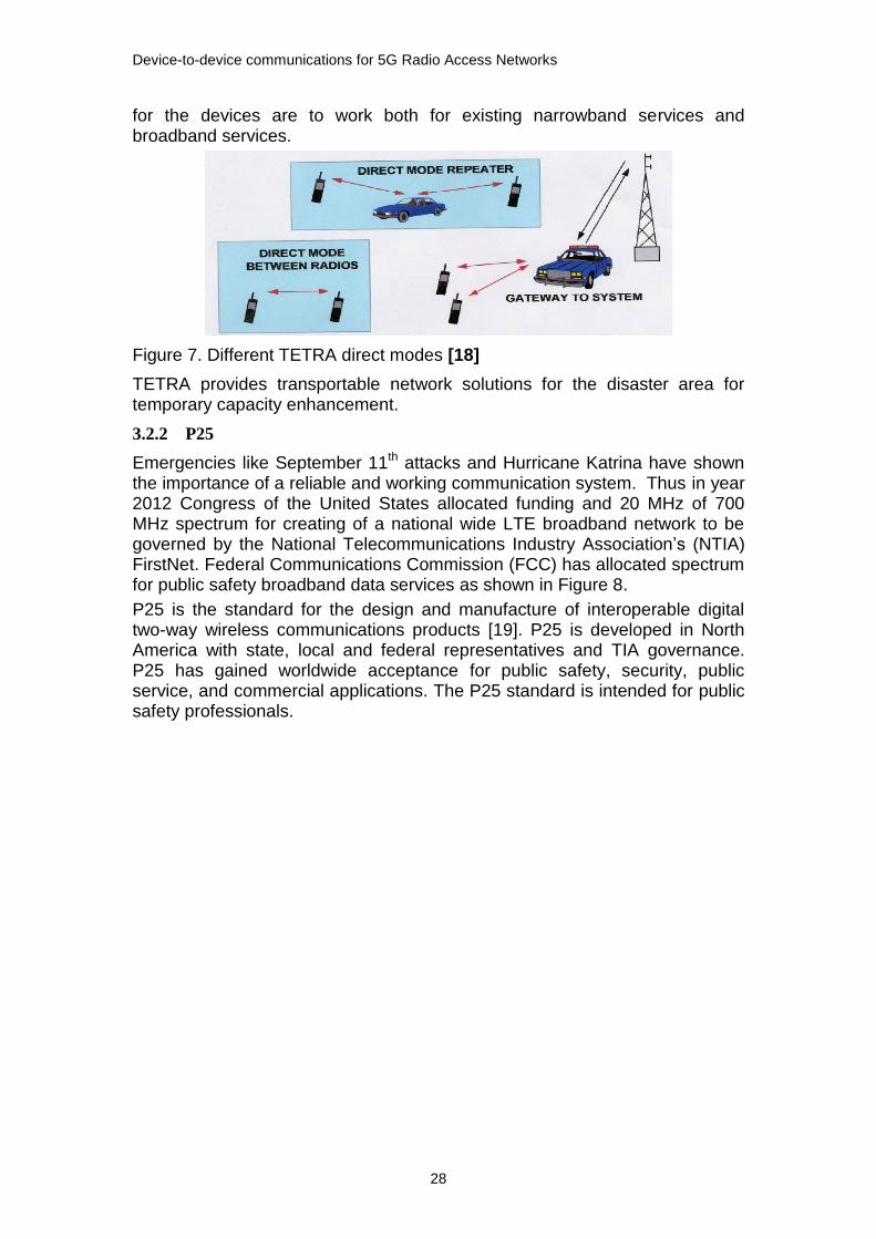
For communication in emergency situation TETRA provides different operational modes shown in Figure 7. TETRA system provides operational modes [18] like:
DMO is a mode of simplex operation where mobile subscriber radio units may communicate using radio frequencies which may be monitored by, but which are outside the control of, the TETRA Trunked Mode Operation (TMO) network. In simplex mode of operation information can be transferred in both directions but not at the same time. DMO is performed without intervention of any BS.
Direct Mode REPeater (DM-REP) is a device that operates in TETRA Direct Mode (DM) and provides a repeater function to enable two or more DM-MSs to extend their coverage range. Two types of DM-REP exist. Type 1 is capable of supporting only a single call on the air interface. Type 2 of DM-REP is capable of supporting two calls on the air interface.
Gateway Mode (GMO) is a mode where a single mobile with connection to the network can act as a relay for other nearby mobiles that are out-of-coverage.
TMO is a mode of operation where MSs communicate via the TETRA V+D air interface which is controlled by the TETRA Switching and Management Infrastructure (SwMI).
Devices used in public safety communication might have specific requirements compared to devices used in commercial networks. Challenges
Device-to-device communications for 5G Radio Access Networks
28
for the devices are to work both for existing narrowband services and broadband services.
Figure 7. Different TETRA direct modes [18]
TETRA provides transportable network solutions for the disaster area for temporary capacity enhancement.
3.2.2 P25
Emergencies like September 11th attacks and Hurricane Katrina have shown the importance of a reliable and working communication system. Thus in year 2012 Congress of the United States allocated funding and 20 MHz of 700 MHz spectrum for creating of a national wide LTE broadband network to be governed by the National Telecommunications Industry Association’s (NTIA) FirstNet. Federal Communications Commission (FCC) has allocated spectrum for public safety broadband data services as shown in Figure 8.
P25 is the standard for the design and manufacture of interoperable digital two-way wireless communications products [19]. P25 is developed in North America with state, local and federal representatives and TIA governance. P25 has gained worldwide acceptance for public safety, security, public service, and commercial applications. The P25 standard is intended for public safety professionals.

Device-to-device communications for 5G Radio Access Networks
29
Figure 8. Spectrum allocated for public safety in P25 [19]
Project 25 has four main objectives [20]:
Ensure competition in system life cycle procurements through Open Systems Architecture
Allow effective, efficient and reliable intra-agency and interagency communications
Provide enhanced functionality and capabilities with a focus on public safety needs
Improve radio spectrum efficiency
LTE-based network will be overlay on the P25 Land Mobile Radio (LRM) network. This will offer speed and low latency for public safety agencies and their advanced multimedia applications.

Device-to-device communications for 5G Radio Access Networks
30
4 3GPP RELEASE 12 FOR PROXIMITY SERVICES
This chapter lists Technical Reports (TRs) and Technical Specification (TSs) in Work Items (WIs) for Proximity Based (ProSe) services in 3GPP Release 12. Additionally it describes functionalities specific for ProSe.
4.1 3GPP RELEASE 12 FOR PROSE
Feasibility Study on Proximity-based Services [21] includes use cases for generic proximity based services and public safety use cases. ProSe are services that can be provided by the 3GPP system based on UEs being in proximity to each other.
ProSe Discovery is a procedure that identifies that a UE is ProSe-enabled ad that it is in proximity of another UE, using Evolved Universal Terrestrial Radio Access (E-UTRA) (with or without E-UTRAN) or Evolved Packet Core (EPC) [22]. ProSe discovery in 3GPP Rel-12 is within network coverage and outside network coverage only for public safety purposes. Discovery within network coverage means discovery under continuous operator network control.
ProSe Communication: a communication between two UEs in proximity by means of communication path established between the UEs. ProSe Communication in 3GPP Rel-12 is within network coverage and outside network coverage only for public safety. Communication within network coverage means communication under continuous operator network control.
Proximity is determined (“a UE is in proximity of another UE”) when given proximity criteria are fulfilled. Proximity criteria can be different for discovery and communication [23]. Proximity criteria are configurable and the operator can configure the proximity criteria to be used.
Public Safety related requirement is additionally group communication.
When UEs are near each other it allows in communication high data rates and low end-to-end delay. When UEs in proximity use direct communication it is more resource-efficient, because no routing through an eNB or possible through the cellular network. Direct communication compared to the normal downlink (DL) and uplink (UL) saves energy and thus improves the radio resource utilization. Using direct path between UEs compared to infrastructure path offloads cellular traffic, reduces congestion and in that way benefits also other cellular UEs. Use cases and possible benefits provided by D2D communication are illustrated in Figure 9.

Device-to-device communications for 5G Radio Access Networks
31
Figure 9. An overview of D2D communication [5]
ProSe related Work Items and their completeness (accessed on 8th of February, 2015) in 3GPP Release 12 are listed in Table 3.
Table 3. ProSe WIs in 3GPP Release 12
Title Completed 3GPP remarks
Study on Proximity-based Services [21]
100%
Proximity-based Services [24] 85% Moved the TR phase to Rel-13 as a stand-alone Study. Triggered by Rel-12 TR 22.803 Study on Proximity-based Services
Study on LTE Device-to-Device proximity Services - Radio Aspects [25]
100% Linked to Rel-12 TR 22.803 Study on Proximity-based Services (FS_ProSe) and Feature ProSe
Group Communication System Enablers for LTE [26]
98% Linked to Rel-12 FS_ProSe TR 22.803 Study on Proximity-based Services
ProSe related work is divided in 3GPP between the System Architecture (SA) working groups (WGs) and the Radio Access Network (RAN) working groups. The SA WSs are responsible for studying the system architecture aspects including architecture, services and security. The RAN WGs are responsible for studying the radio aspects including synchronization, discovery and communication.
Each WI has one or more TRs and/or TSs. TRs or TSs for ProSe WIs in 3GPP Release 12 are:
WI Study on Proximity-based Services [21]
TR 22.803 Feasibility study on Proximity-based Services [27]
WI Proximity -based Services [24]
TS 23.303 Proximity-based services (ProSe); Stage 2 [28]
TR 33.833 Study on security issues to support Proximity Services [29]
Device-to-device communications for 5G Radio Access Networks
32
TR 23.703 Study on architecture enhancements to support Proximity-based Services (ProSe) [22]
TS 22.115 Service aspects; Charging and billing [30] 1)
TS 23.401 General Packet Radio Service (GPRS) enhancements for Evolved Universal Terrestrial Radio Access Network (E-UTRAN) access [31] 1)
TS 22.278 Service requirements for the Evolved Packet System (EPS) [23] 1)
TS 33.303 Proximity-based Services (ProSe); Security aspects [32]
WI Study on LTE Device-to-Device Proximity Services - Radio Aspects [25]
TR 36.843 Study on LTE device to device proximity services; Radio aspects [33]
WI Group Communication System Enablers for LTE [26]
TR 36.868 Evolved Universal Terrestrial Radio Access (E-UTRA); Study on group communication for E-UTRA [34]
1) These TSs already have versions for 3GPP Release 13.
4.2 PROSE FOR PUBLIC SAFETY AND PROSE SERVICES
Scope of the ProSe feasibility study was to study the use cases and based on the use cases identify possible requirements related to discovery and communication between UEs in proximity to each other [27]. Only in public safety use cases discovery and communication can take place in absence of E-UTRAN coverage.
4.2.1 PUBLIC SAFETY USE CASES
A Public Safety -enabled UE can operate in public safety spectrum for public safety Services, and in MNO commercial spectrum for general services, general services like voice call. Public safety spectrum is used only for public safety ProSe. Public Safety -enabled UEs can communicate with each other using ProSe communication even though they belong to different Home Public Land Mobile Networks (HPLMNs). When E-UTRAN coverage is not available, a Public Safety -enabled UE can automatically use ProSe communication. When E-UTRAN coverage is available, the user can manually set the UE to use direct discovery and communication. Additionally all public safety users utilize ProSe-enabled UEs, and ProSe supports both UE discovery and UE Communication.
In an emergency situation, when the network cannot be achieved, communication with the people at the incident needs to work, e.g. people in damaged buildings [33]. After a natural disaster or power cuts a fall back is needed. That happens when a previously worked complete network failures. One use case is to provide extra capacity for an incident, when the existing system is not able to provide additional capacity. Extra capacity is needed for example for adding more group members into the public safety application. There are local communication requirements that are valid when no need to connect back to public safety control.
Communication needs to work when the UEs are within coverage, out-of-coverage, partially in-coverage and out-of-coverage. Information about those

Device-to-device communications for 5G Radio Access Networks
33
users that are in different coverage scenarios needs to be available at any time.
Public safety device discovery and communication can operate on ProSe specific carrier, i.e. spectrum reserved for public safety, or on a carrier also user for LTE network coverage, i.e. LTE spectrum.
4.2.2 DIRECT COMMUNICATION SCENARIOS
ProSe direct communication is a communication between two or more UEs in
proximity that are ProSe-enabled, by means of user plane (U-plane)
transmission using E-UTRA technology via a path not traversing any network
node [22]. Table 4. shows the scenarios for device discovery and direct
communication within network coverage and outside network coverage. UE is
out-of-coverage when the average SINR from the network is less than -6 dB
[33].
Table. 4 In-coverage and out-of-coverage scenarios for ProSe
Main D2D topics In-Coverage Out-of-Coverage
Discovery Non-PS and PS requirements PS only
Direct Communication At least PS PS only
There can be or there are multiple different direct communication scenarios when taken into account registered Public Land Mobile Network (PLMN), direct communication path and coverage status (in coverage or out of coverage) [22]. Table 5. shows different ProSe direct communication scenarios.
Table 5. ProSe direct communication scenarios
Scenarios UE1 UE2
A1 Out-of-Coverage Out Out
B1 Partial Coverage In Out
C1 In-Coverage-Singe-Cell In In
D1 In-Coverage-Multi-Cell In In
E1 Different PLMN and different cells In In
F1 Different PLMN and different cell, one UE is in coverage common to both cell, and the other UE is in serving cell’s coverage
In In
G1 Different PLMN and different cells, both UEs are in its own serving cell’s coverage
In In
In Table 5. In stands for In-Coverage and Out stands for Out-of-Coverage.
Figures 10. to 16. show the different ProSe direct communication scenarios supported by E-UTRAN. Scenario 1A in Figure 10. is only for public safety. Scenarios 1A, 1B, 1C and 1D will cover public safety scenarios in 3GPP Release 12 [33].

Device-to-device communications for 5G Radio Access Networks
34
Figure 10. UEs are out-of-coverage (scenario 1A) [22]
Figure 11. UEs with partial coverage (scenario 1B) [22]
Figure 12. Both UEs are in coverage of one cell (scenario 1C) [22]
Figure 13. Both UEs are in-coverage of multiple cells (scenario 1D) [22]
Device-to-device communications for 5G Radio Access Networks
35
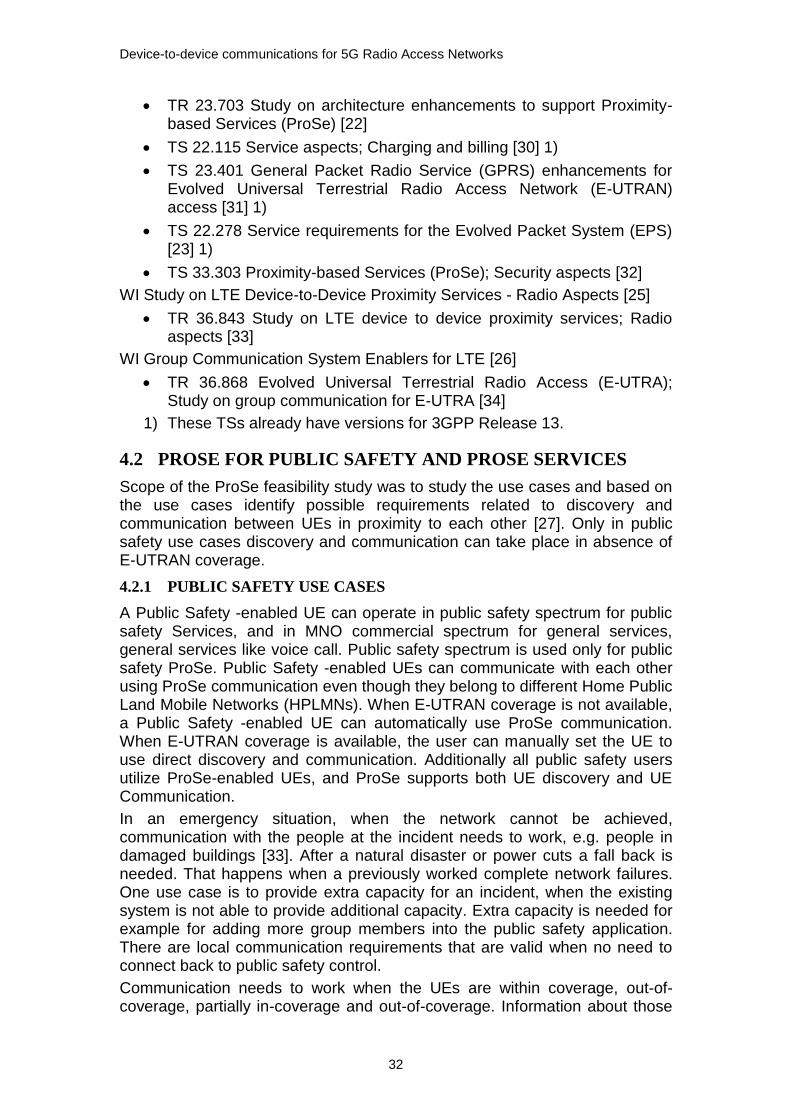
Figure 14. UEs are in different cells and PLMNs (scenario 1E) [22]
Figure 15. UEs are in different PLMNs and one UE is in common cell coverage (scenario 1F) [22]
Figure 16. UEs are in different cells and different PLMNs (scenario 1G) [22]
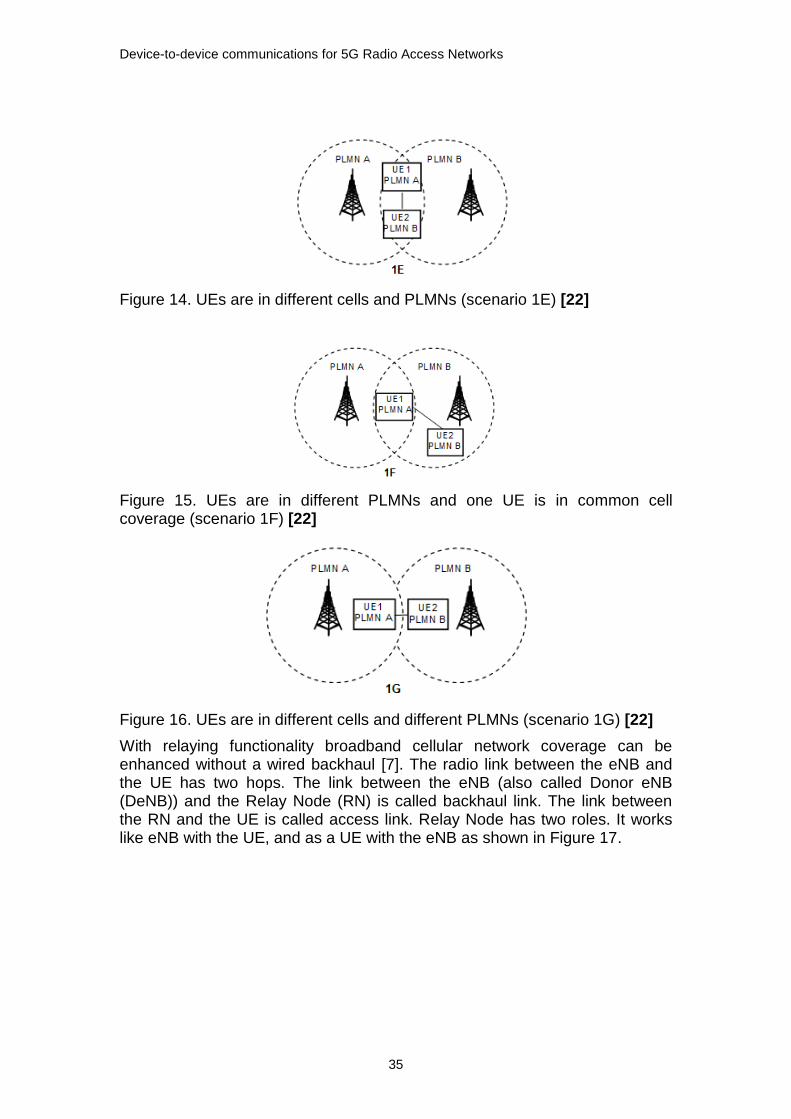
With relaying functionality broadband cellular network coverage can be enhanced without a wired backhaul [7]. The radio link between the eNB and the UE has two hops. The link between the eNB (also called Donor eNB (DeNB)) and the Relay Node (RN) is called backhaul link. The link between the RN and the UE is called access link. Relay Node has two roles. It works like eNB with the UE, and as a UE with the eNB as shown in Figure 17.
Device-to-device communications for 5G Radio Access Networks
36
Figure 17. Relaying [7]
There are two types of relays [7]. The first type is amplify-and-forward relays or repeaters which amplify and forward the received analog signal forward. This means that the repeater amplify also noise and interference. The second type is decode-and-forward delay. These relays decode and re-encode the received signal before forwarding it to the receiver.
In a situation when some of the Public Safety -enabled UEs are within network coverage and some are not, those Public Safety -enabled UEs within network coverage may relay the radio resource management control to the Public Safety -enabled UEs not within network coverage [27].
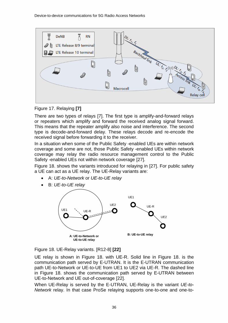
Figure 18. shows the variants introduced for relaying in [27]. For public safety a UE can act as a UE relay. The UE-Relay variants are:
A: UE-to-Network or UE-to-UE relay
B: UE-to-UE relay
Figure 18. UE-Relay variants. [R12-8] [22]
UE relay is shown in Figure 18. with UE-R. Solid line in Figure 18. is the communication path served by E-UTRAN. It is the E-UTRAN communication path UE-to-Network or UE-to-UE from UE1 to UE2 via UE-R. The dashed line in Figure 18. shows the communication path served by E-UTRAN between UE-to-Network and UE out-of-coverage [22].
When UE-Relay is served by the E-UTRAN, UE-Relay is the variant UE-to-Network relay. In that case ProSe relaying supports one-to-one and one-to-
UE1 UE-R
UE2
UE1
UE-R
UE2
A: UE-to-Network or
UE-to-UE relay
B: UE-to-UE relay
Device-to-device communications for 5G Radio Access Networks
37
many communication from E-UTRAN to UE out-of-coverage and wise versa. When the UE-Relay is served by the E-UTRAN or not, the UE-relay can be the UE-to-UE relay variant. The UE-to-UE relay can relay one-to-one or one-to-many communication for public safety ProSe-enabled UEs which are within its communication range [22].
4.2.3 CONTROL MODES FOR D2D SCENARIOS
The C-plane, the data plane (U-plane) and the management plane are the three basic components of a telecommunications architecture. The data plane is the part of a network that carries user traffic. The data plane enables data transfer to and from clients, handling multiple conversations through multiple protocols, and manages conversations with remote peers. The C-plane is the part of a network that carries signalling traffic and is responsible for routing. Functions of the C-plane include system configuration and management. The C-plane and management plane serve the data plane. The management plane carries administrative traffic, and is a subset of the C-plane.
In the current cellular network C-plane exists between the UE and the network. The network controls the UEs. However it is not feasible to have network control for D2D pairs as they in proximity to each other. Network control would just be 'over-design' of control. Instead the C-plane is split between the UE and the network.
Data paths
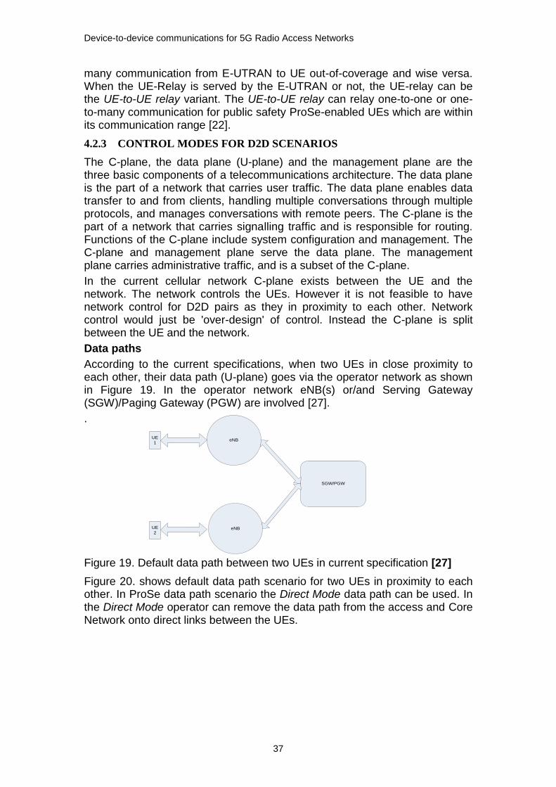
According to the current specifications, when two UEs in close proximity to each other, their data path (U-plane) goes via the operator network as shown in Figure 19. In the operator network eNB(s) or/and Serving Gateway (SGW)/Paging Gateway (PGW) are involved [27].
.
Figure 19. Default data path between two UEs in current specification [27]
Figure 20. shows default data path scenario for two UEs in proximity to each other. In ProSe data path scenario the Direct Mode data path can be used. In the Direct Mode operator can remove the data path from the access and Core Network onto direct links between the UEs.
UE
1
UE
2
eNB
eNB
SGW/PGW

Device-to-device communications for 5G Radio Access Networks
38
Figure 20. Communication between two UEs using Direct Mode data path [27]
Figure 21. shows the data path in the EPS for communication between two UEs that are served by the same eNB. ProSe scenario is where data path in the EPS for two UEs communicating is 'locally-routed' when the UEs are served by the same eNB.
Figure 21. The data path for two UEs served by the same eNB [27]
Control paths for ProSe communication
Examples of ProSe data paths shown in Figure 20. and Figure 21. can have multiple control path options. 3GPP Working Groups are expected to define and specify those to be used for ProSe. Figure 22., Figure 23. and Figure 24. show examples of possible control paths.
Figure 22. An example of control path for network-supported ProSe communication when the UEs are served by the same eNB [27]
UE
1
UE
2
eNB
eNB
SGW/PGW
UE
1
UE
2
eNB
eNB
SGW/PGW
UE2
eNB EPC
UE1
Device-to-device communications for 5G Radio Access Networks
39
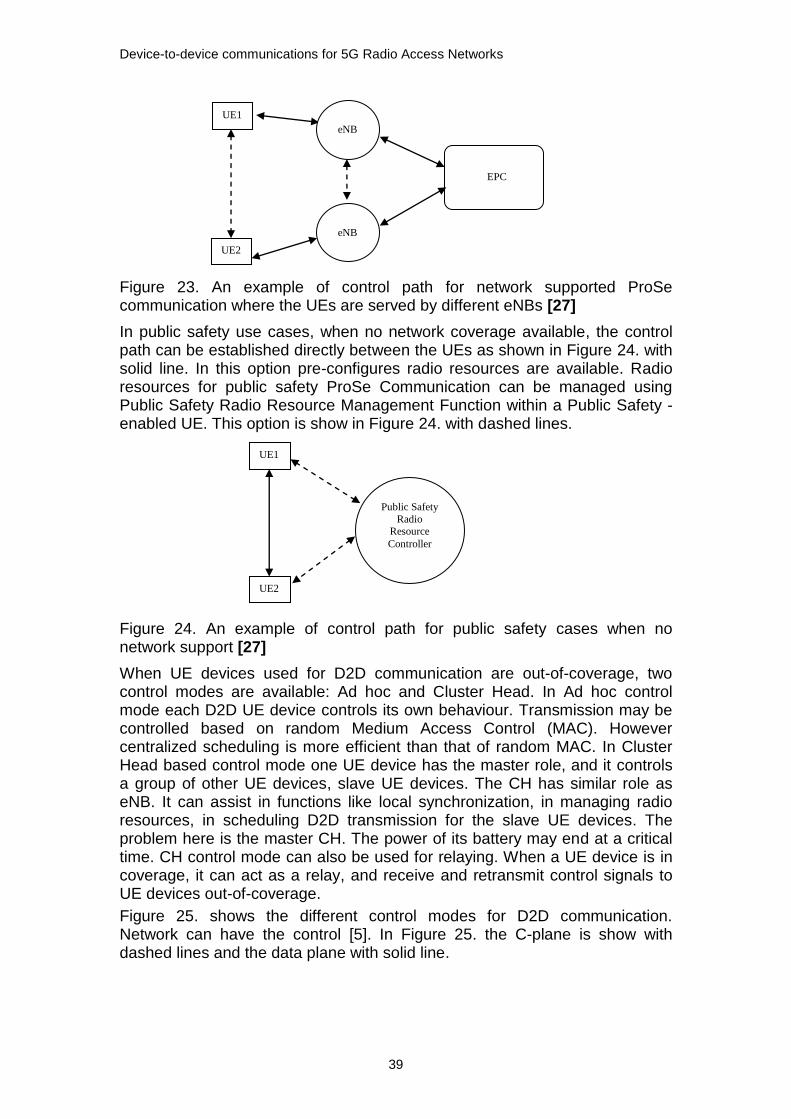
Figure 23. An example of control path for network supported ProSe communication where the UEs are served by different eNBs [27]
In public safety use cases, when no network coverage available, the control path can be established directly between the UEs as shown in Figure 24. with solid line. In this option pre-configures radio resources are available. Radio resources for public safety ProSe Communication can be managed using Public Safety Radio Resource Management Function within a Public Safety -enabled UE. This option is show in Figure 24. with dashed lines.
Figure 24. An example of control path for public safety cases when no network support [27]
When UE devices used for D2D communication are out-of-coverage, two control modes are available: Ad hoc and Cluster Head. In Ad hoc control mode each D2D UE device controls its own behaviour. Transmission may be controlled based on random Medium Access Control (MAC). However centralized scheduling is more efficient than that of random MAC. In Cluster Head based control mode one UE device has the master role, and it controls a group of other UE devices, slave UE devices. The CH has similar role as eNB. It can assist in functions like local synchronization, in managing radio resources, in scheduling D2D transmission for the slave UE devices. The problem here is the master CH. The power of its battery may end at a critical time. CH control mode can also be used for relaying. When a UE device is in coverage, it can act as a relay, and receive and retransmit control signals to UE devices out-of-coverage.
Figure 25. shows the different control modes for D2D communication. Network can have the control [5]. In Figure 25. the C-plane is show with dashed lines and the data plane with solid line.
UE2
UE1
EPC
eNB
eNB
UE2
UE1
Public Safety
Radio
Resource
Controller

Device-to-device communications for 5G Radio Access Networks
40
Figure 25. Control modes for different D2D scenarios [5]
4.3 ARCHITECTURAL ENHANCEMENTS FOR PROSE
This chapter describes the architectural reference model, and functions needed for 3GPP system to enable ProSe services. The functions are EPC-level ProSe Discovery, EPC support for WLAN direct discovery and communication, Direct discovery, Direct communication, and UE-to-Network Relay.
4.3.1 REFERENCE ARCHITECTURAL MODEL
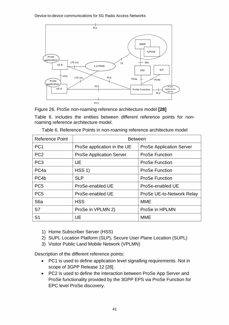
For the 3GPP system enabling ProSe services following architectural reference models [28] have been specified; non-roaming reference architecture, inter-PLMN reference architecture and roaming reference architecture. Figure 26. shows non-roaming inter-PLM reference architecture model where HPLMN of UE A is PLMN A, and HPLMN of UE B is PLMN B.
ProSe server functionality in the Mobility Management Entity (MME) is used for authorizing the ProSe discovery and/or ProSe communication. Application running in the UE asks for ProSe service from the EPC layer functionality in the UE. ProSe server allocates the ProSe ID for each application instance in the UE. The ProSe ID is used for ProSe discovery and ProSe communication. The ProSe ID is sent to the ProSe application server, and it is distributed to other users who are allowed to discover this user.
Device-to-device communications for 5G Radio Access Networks
41
Figure 26. ProSe non-roaming reference architecture model [28]
Table 6. includes the entities between different reference points for non-roaming reference architecture model.
Table 6. Reference Points in non-roaming reference architecture model
Reference Point Between
PC1 ProSe application in the UE ProSe Application Server
PC2 ProSe Application Server ProSe Function
PC3 UE ProSe Function
PC4a HSS 1) ProSe Function
PC4b SLP ProSe Function
PC5 ProSe-enabled UE ProSe-enabled UE
PC5 ProSe-enabled UE ProSe UE-to-Network Relay
S6a HSS MME
S7 ProSe in VPLMN 2) ProSe in HPLMN
S1 UE MME
1) Home Subscriber Server (HSS)
2) SUPL Location Platform (SLP), Secure User Plane Location (SUPL)
3) Visitor Public Land Mobile Network (VPLMN)
Description of the different reference points:
PC1 is used to define application level signalling requirements. Not in
scope of 3GPP Release 12 [28].
PC2 is used to define the interaction between ProSe App Server and
ProSe functionality provided by the 3GPP EPS via ProSe Function for
EPC level ProSe discovery.
UE B
ProSe application
LTE-Uu
E-UTRAN
UE A
S1
ProSe Function
MME
S/PGW
HSS
ProSe application
HSS SLP
ProSe Application
Server
S6a
PC3 PC4a PC4b
PC2
PC1
PC3
LTE-Uu PC5
PC1

Device-to-device communications for 5G Radio Access Networks
42
PC3 is used to define the interaction between UE and ProSe Function.
PC3 authorises direct discovery requests, and perform allocations of
ProSe Application Codes and ProSe Application Identities that are
used for direct discovery. It is used to define the authorisation policy
per PLMN for ProSe direct discovery (for public safety and non-public
safety) and communication (for public safety only) between UE and
ProSe Function. In case of public safety it is also used to provision
parameters in the PMCE that are needed when the UE is not served by
E-UTRA.
PC4a is used to provide subscription information in order to authorise
access for direct services in a PLMN.
PC4b It is used to provide subscription information in order to allow the
ProSe Function to authorise direct discovery requests.
PC5 directly used for C-plane and U-plane for direct discovery and
communication, for delay and one-to-one communication.
S6a in case of ProSe S6a is used to download ProSe related
subscription information to MME during E-UTRAN attach procedure or
to inform MME subscription information in the HSS has changed.
S7 is used for HPLMN control of ProSe service authorization.
ProSe Function
The ProSe Function consists of three main sub-functions:
Direct Provisioning Function (DPF)
Direct Discovery Name Management
EPC-level Discovery Function
DPF provides the UE with necessary parameters so that it is able to use ProSe Direct Discovery and Prose Direct Communication. It is used to provide the UEs with PLMN specific parameters that allow the UE to use ProSe in this specific PLMN. In addition for direct communication used for public safety, DPF provides the UE with parameters that are needed when the UE is not served by E-UTRAN.
Direct Discovery Name Management Function is used for open Prose Direct Discovery. ProSe Direct Discovery uses ProSe Applications IDs and ProSe Application Codes, and Direct Discovery Name Management Function allocates and processes them. It authorizes each discovery request and uses for that ProSe related subscriber data stored in HSS. Additionally it provides the UE with the necessary security material in order to protect discovery messages transmitted over the air.
EPC-level Discovery ProSe Function includes multiple functionalities related to direct discovery and communication. The ProSe Function provides the necessary charging and security information for usage of ProSe.

Device-to-device communications for 5G Radio Access Networks
43
Figure 27. ProSe Function Interfaces to other network elements and PLMNs [22]
Figure 28. UE to ProSe Function Interfaces for each sub-function [22]
Figure 27. shows the ProSe Function Interfaces to other network elements and PLMNs, and Figure 28. shows the UE to ProSe Function Interfaces for each sub-function.
4.3.2 EPC-LEVEL PROSE DISCOVERY
Device discovery is one of the key issues in direct D2D communication. For D2D communication to take place two UEs need to discover each other.
EPC-level ProSe discovery is a ProSe discovery procedure by which the EPS determines the proximity of two ProSe-enabled UEs and informs them of their proximity [22].
ProSe-enabled UE: A UE that supports ProSe requirements and associated procedures. Unless explicitly stated otherwise, a ProSe-enabled UE refer both to a non-Public Safety-enabled UE and a Public Safety -enabled UE.
Figure 29. shows architecture reference model for LTE based solution for direct discovery.
DPF
Direct Discovery
Name Mgmt Function
EPC - level Discovery Function
HPLMN ProSe
Function
HSS SLP
DPF
Direct Discovery
Name Mgmt Function
VPLMN ProSe
Function
DPF
Direct Discovery
Name Mgmt Function
Local PLMN ProSe
Function
PC6
PC7 PC4b
PC4a
DPF
Direct Discovery
Name Mgmt Function
EPC - level Discovery Function
HPLMN ProSe Function
UE
DPF
PC 3

Device-to-device communications for 5G Radio Access Networks
44
Figure 29. Architectural reference model for direct discovery (non-roaming) [22], [28]
The basic direct discovery concept is shown in Figure 29. Assumption is that each PLMN has a Direct Provisioning Function (DFP). UE obtains, in a secure way, configuration for direct services from DFP. UE obtains from DPF in PLMNs also if it is authorized to perform direct discovery [22].
Direct discovery (non-roaming) introduces three new reference points; PC3, PC6a and PC5. PC3 is between UE and Home DPF (H-DPF) or between UE and a DPF in a local PLMN. In the local PLMN the UE is authorized by the H-DPF to perform direct services. PC3 enables PLMN-specific direct service authorization. PC6a is between DFP in a local PLMN and H-DPF. It enables the DPF in a local PLMN to obtain authorization information for the UE. This is not a roaming interface. PC5 is between UEs. It is used for all control and U-plane information exchange needed for performing direct discovery between two UEs [22].
Figure 30. Architecture for EPC-level discovery using C-plane location services [22]

Device-to-device communications for 5G Radio Access Networks
45
Figure 31. Architecture for EPC-level discovery using U-plane location services [22]
There are three new reference points: PC2, PC3 and PC6.
PC3 is reference point between UE and ProSe Function. It is used for ProSe registration, proximity requests and proximity alerts. The PC3 protocol runs in the U-plane of EPS.
PC2 is reference point between ProSe Function and Third party Application Server (AS). It is used for ProSe registration and identifier retrieval.
PC6 is reference point between ProSe Function residing in the HPLMN of the discoverer and the ProSe Function residing in the HPLMN of the discoveree. It is used when the discoverer and the discoveree(s) are subscribers of different PLMNs.
ProSe Function stores subscriber's ProSe profile and acts as a location services client (LCS client or SLP client). It interacts with a Third party AS via the PC2 reference point, and interacts with the UE via the PC3 reference point. ProSe Function communicates with ProSe Function peers in other PLMNs over the PC6 reference point to support cross-PLMN EPC-level ProSe discovery scenarios. ProSe Function provides the UE with information to assist with WLAN Direct discovery and WLAN Direct communication. It may have interfaces to the charging architecture.
Figure 30. shows architecture for EPC-level discovery using C-plane location services, and Figure 31. shows architecture for EPC-level discovery using U-plane location services.
4.3.3 EPC SUPPORT FOR WLAN DIRECT DISCOVERY AND
COMMUNICATION
EPC-level ProSe discovery is a process by which the EPC determines the proximity of two ProSe-enabled UEs and informs them of their proximity [22].
4.3.4 DIRECT DISCOVERY
ProSe Direct Discovery is a procedure employed by a ProSe-enabled UE to discover other ProSe-enabled UEs in its vicinity by using only the capabilities of the two UEs with Rel-12 E-UTRA technology. [28]
ProSe Direct Discovery is either open and or restricted. In open discovery there is no explicit permission that is needed from the UE being discovered. In

Device-to-device communications for 5G Radio Access Networks
46
restricted discovery an explicit permission from the UE that is being discovered is required. [27]
Two ProSe discovery models for direct discovery have been identified: Model A ('I am here') and Model B ('who is there'/'are you there') [22].
Model A has two roles: Announcing UE and Monitoring UE. Announcing UE broadcasts discovery messages at pre-defined discovery intervals. UE(s) i.e. Monitoring UEs in the proximity can read the messages, and if interested can process them. The nearby UE needs to have permission for discovering. Figure 32. shows Announcing UE and Monitoring UE in different PLMNs.
Also Model B introduces two roles: Discoverer UE and Discoveree UE. Discoverer UE transmits a request message with certain information about what it is interested to discover. Discoveree UE receives the request message and can respond to the request message with some information related to the discoverer’s request [28] , [22].
Figure 32. Announcing and monitoring UE roles in different PLMNs [22]
Figure 33. ProSe direct discovery procedure [22]

Device-to-device communications for 5G Radio Access Networks
47
Figure 33 shows steps for direct discovery and different entities which are involved in the discovery procedure. Expression Code is used in the steps, and it is defined as follows: Expression Code: an identity, which the ProSe enabled UE uses for broadcasting its identity and used in discovery. The expression is an alias for the ProSe ID (identifier) for ProSe enabled users. The expression code may be sent in open or as an encrypted expression [22].
Step 1: An application requests the allocation of an Expression Code
from the ProSe manager in the UE.
Step 2: Expression Code has been allocated. This procedure is only
done the first time an Expression Code is allocated.
Step 3: The ProSe Manager in the UE provides an Expression Code to
the application.
Step 4 (optional): The application may share this Expression Code with
the interested parties using application layer mechanism. This step is
not necessary for open discovery.
Step 5: If the UE is authorized to perform discovery, the application via
the ProSe Manager initiates the announcing of the Expression Code by
the 3GPP layers.
Step 6: The UE starts broadcasting the related Expression Code.
Broadcast can be repeated in a configurable interval.
Step 7: The application sends a request to the ProSe manager of the
UE to monitor for an expression code.
Step 8: If the UE is authorized to perform discovery, ProSe Manager of
the UE monitors the requested Expression Code. It then detects the
Code of the announcing UE.
Step 9: The ProSe Manager of the UE passes the detected Expression
Code to the application.
4.3.5 DIRECT COMMUNICATION
ProSe direct Communication: A communication between two or more UEs in proximity that are ProSe-enabled by means of U-plane transmission using E-UTRA technology via a path not traversing any network node [22] [28].
There are two different ProSe direct communication modes that are supported by E-UTRAN [22]:
Network independent direct communication
Network authorized direct communication.
Network independent direct communication mode is enabled only for ProSe-enabled UE and does not require any network assistance. ProSe-enabled UE provides all needed information for performing direct communication. This mode of operation goes for pre-authorize ProSe-enabled Public Safety UE, and in direct communication for one-to-one and for one-to-many. Network independent direct communication mode needs to work when UE is served by E-UTRAN and when it is not.
In Network authorized direct communication mode, direct communication is always network assisted by EPC. This mode of operation is used when both

Device-to-device communications for 5G Radio Access Networks
48
UEs are served by E-UTRAN, and ProSe direct communication is one-to-one. Additionally for Public Safety -enabled UEs it may apply when only one UE is served by E-UTRAN.
Direct communication includes one-to-one, one-to-many/unicast, one-to-many/broadcast, and on-hop relay functionalities. Access priorities and session transfer from direct-based communication path to network-based one are considerations as well [6]. Broadcast do not have close loop feedback, so it means no support for HARQ (Hybrid ARQ) in public safety networks like Project 25 and TETRA.
One-to-many ProSe Direct Communication is applicable only to ProSe-enabled Public Safety -enabled UEs. And applied when the UE is authorised, and served by E-UTRAN, and when the UE is outside of E-UTRA coverage [28].
Direct communication one-to-many (decentralised mode) is applicable only to Public Safety -enabled UEs. One-to-many can be apply when the UE is served by E-UTRA or not, if authorised. One-to-many communication mode is connectionless and so there is no over PC5 C-plane signalling. No Quality of Services (QoS) support but only priority handling. The U-plane interface to the D2D radio layer is IP packets carried over radio bearers. All user data for the group can be encrypted and decrypted using a group security key. Authorisation for direct communication one-to-many is pre-configured in the UE by the ProSe Function using PC3c reference point. ProSe UE configuration parameters (e.g. including ProSe Group IP multicast addresses, ProSe Group IDs, Group security material, radio related parameters) are be pre-configured in the UE [22]
E-UTRAN procedures for group communication [34]:
Group communication using unicast bearers
Group communication using Multimedia Broadcast / Multicast Service (MBMS)
ProSe Group communication [23]: a one-to-many ProSe E-UTRA communication, between more than two Public Safety ProSe-enabled UEs in proximity, by means of a common ProSe E-UTRA Communication path established between the Public Safety ProSe-enabled UEs.
4.3.6 UE-TO-NETWORK RELAY
ProSe UE-to-Network Relay: A UE that provides functionality to support connectivity to ‘unicast’ services for Remote UE(s) [28]. Remote UE: A ProSe-enabled Public Safety UE, that is not served by E-UTRAN, and that communicates with a Packet Data Network (PDN) via a ProSe UE-to-Network Relay [28].
ProSe UE-to-Network Relay: is a form of relay in which a Public Safety ProSe-enabled UE acts as ProSE E-UTRA Communication relay between Public Safety ProSe-enabled UE and the ProSe-enabled network using E-UTRA [23].
For public safety use cases ProSe Direct Communication shall be used for ProSe UE-to-Network Relay. It is relay between E-UTRAN and UEs not served by E-UTRAN shown in Figure 34. ProSe UE-to-Network Relay will be used for public safety purposes. It shall be a generic function that can relay
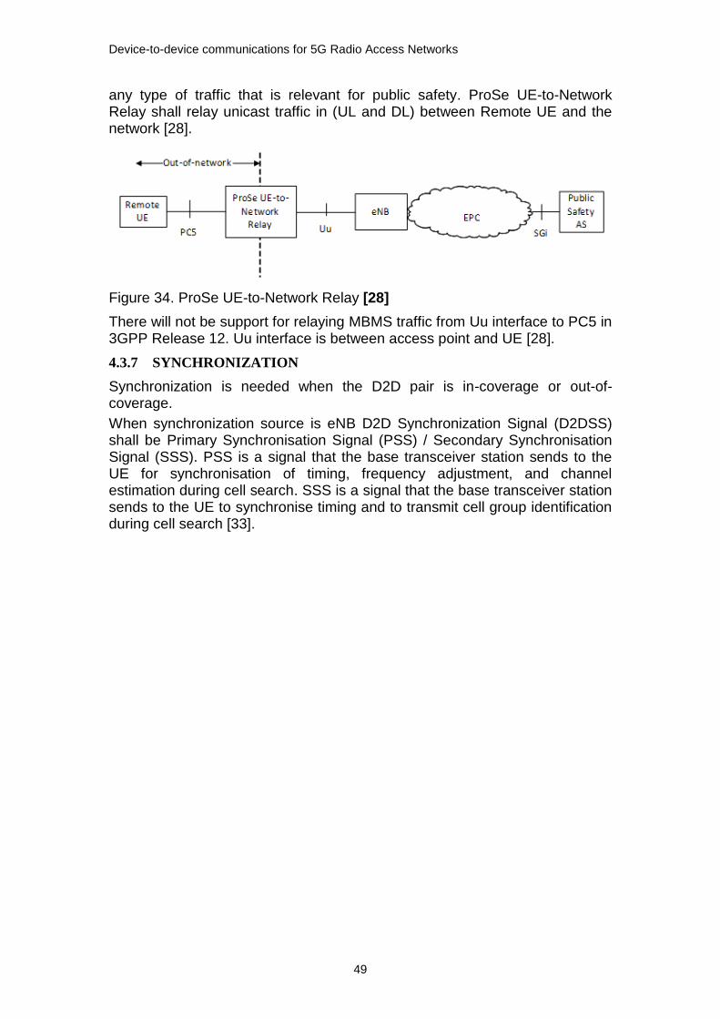
Device-to-device communications for 5G Radio Access Networks
49
any type of traffic that is relevant for public safety. ProSe UE-to-Network Relay shall relay unicast traffic in (UL and DL) between Remote UE and the network [28].
Figure 34. ProSe UE-to-Network Relay [28]
There will not be support for relaying MBMS traffic from Uu interface to PC5 in 3GPP Release 12. Uu interface is between access point and UE [28].
4.3.7 SYNCHRONIZATION
Synchronization is needed when the D2D pair is in-coverage or out-of-coverage.
When synchronization source is eNB D2D Synchronization Signal (D2DSS) shall be Primary Synchronisation Signal (PSS) / Secondary Synchronisation Signal (SSS). PSS is a signal that the base transceiver station sends to the UE for synchronisation of timing, frequency adjustment, and channel estimation during cell search. SSS is a signal that the base transceiver station sends to the UE to synchronise timing and to transmit cell group identification during cell search [33].
Device-to-device communications for 5G Radio Access Networks
50
5 METIS APPROACH TO D2D COMMUNICATION
This chapter describes on high level the METIS project [4] approach to D2D, and the methodology it uses, i.e. Work Packages (WPs), Technology Components (TeCs), Horizontal Topics (HTs), HT specific concepts, and Building Blocks (BBs). The main focus is on the HT D2D communication as device-to-device communication is the scope of this thesis.
I have divided the TeCs enablers for HT D2D communication into the following three groups:
The currently most promising TeCs, based on link and system
simulations, which have been selected for further study [D6.3]
TeCs mapped in the METIS interim phase to HT D2D concept [D6.2]
TeCs enablers for HT D2D communication, not in the first or second
category, selected by the WP owners as promising TeCs enablers for
D2D
The chapter first lists TeCs from WPs point of view. WPs are processes to TeCs, and TeC are enablers for HTs. TeCs in WPs enablers for HT D2D have been selected. WPs include mapping of TeCs to HTs or mapping via TCs to HTs.
Secondly the chapter describes the TeCs enablers for D2D communication from HT D2D concept point of view. I have grouped the TeCs following the HT D2D concept structure. TeCs enablers for HT D2D are described in more detail.
The chapter includes also a short view on the intermediate system concept and system architecture, and D2D specific BBs.
Appendixes (A, B, C and D) include all TeCs in WP2, WP3, WP4 and WP5 accordingly as not all TeCs are listed in this chapter based on the grouping described. In some later phase, when the TeCs are mature enough, some of them might become enablers for HT D2D.
5.1 OVERVIEW OF METIS
The 7th Framework Programme project, METIS, is a consortium of vendors, five operators, thirteen academic organization, automotive industry and T&M vendor. It was established for answering to growing demands for beyond 4G mobile and wireless communication systems. The objective of METIS project is as follows: 'METIS will lay the foundation for the 5G mobile and wireless communications system.' METIS project started on 1st of November 2012, and will end on 30th of April 2015 [4].

Device-to-device communications for 5G Radio Access Networks
51
The target of the METIS project is to provide technical enablers for defining the requirements and solutions for realizing the scenarios. METIS objective is to develop one 5G system concept that fulfils the METIS goals and the requirements of the 2020 connected information society. METIS has defined and uses HTs to simplify the system development [35].
The path from METIS test cases (TCs) to the solutions, which will be provided by METIS project, starts from HT concepts which build an overall system concept and further an Intermediate METIS 5G system concept. The final METIS 5G system concept will provide solutions for METIS test cases. We are in the phase of intermediate METIS 5G system concept.
METIS presents the following five scenarios for 5G mobile and wireless systems [36]:
1. “Amazingly fast” focuses on high data-rates for future mobile broadband users,
2. “Great service in a crowd” focuses on mobile broadband experience even in the very crowded areas and conditions,
3. “Ubiquitous things communicating” focuses on efficient handling of a very large number of devices (including e.g. machine type of devices, and sensors) with widely varying requirements,
4. “Best experience follows you” focuses on end-users on the move with high levels of experience, and
5. “Super real-time and reliable connections” focuses on new applications and use cases with very strict requirements on latency and reliability.
METIS has also defined overall technical goals for enabling the fulfilment of the scenarios. The METIS overall technical goals are:
1000 times higher mobile data volume per area
10 times to 100 times higher number of connected devices
10 times to 100 times higher typical user data rate
10 times longer battery life for low power Massive Machine
Communication devices
5 times reduced End-to-End latency
Energy efficiency and cost
Additionally METIS has specified twelve test cases based on the METIS scenarios. The TCs will be further used when designing and evaluating the technical solutions. So each TC includes a problem description, a set of assumptions, constraints, requirements and Key Performance Indicators (KPIs). Each TCs has been created from end-user point of view. The twelve TCs are [36]:
TC 1: Virtual reality office
TC 2: Dense urban Information society
TC 3: Shopping mall
TC 4: Stadium
TC 5: Teleprotection in smart grid network
TC 6: Traffic jam
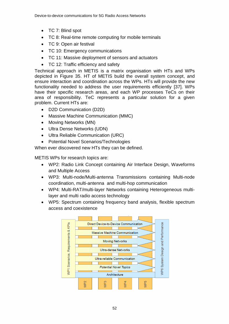
Device-to-device communications for 5G Radio Access Networks
52
TC 7: Blind spot
TC 8: Real-time remote computing for mobile terminals
TC 9: Open air festival
TC 10: Emergency communications
TC 11: Massive deployment of sensors and actuators
TC 12: Traffic efficiency and safety
Technical approach in METIS is a matrix organisation with HTs and WPs depicted in Figure 35. HT of METIS build the overall system concept, and ensure interaction and coordination across the WPs. HTs will provide the new functionality needed to address the user requirements efficiently [37]. WPs have their specific research areas, and each WP processes TeCs on their area of responsibility. TeC represents a particular solution for a given problem. Current HTs are:
D2D Communication (D2D)
Massive Machine Communication (MMC)
Moving Networks (MN)
Ultra Dense Networks (UDN)
Ultra Reliable Communication (URC)
Potential Novel Scenarios/Technologies
When ever discovered new HTs they can be defined.
METIS WPs for research topics are:
WP2: Radio Link Concept containing Air Interface Design, Waveforms
and Multiple Access
WP3: Multi-node/Multi-antenna Transmissions containing Multi-node
coordination, multi-antenna and multi-hop communication
WP4: Multi-RAT/multi-layer Networks containing Heterogeneous multi-
layer and multi radio access technology
WP5: Spectrum containing frequency band analysis, flexible spectrum
access and coexistence
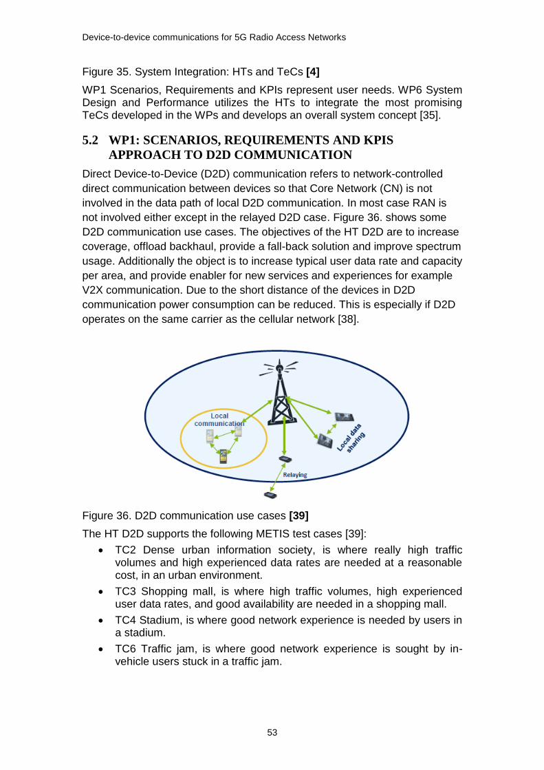
Device-to-device communications for 5G Radio Access Networks
53
Figure 35. System Integration: HTs and TeCs [4]
WP1 Scenarios, Requirements and KPIs represent user needs. WP6 System Design and Performance utilizes the HTs to integrate the most promising TeCs developed in the WPs and develops an overall system concept [35].
5.2 WP1: SCENARIOS, REQUIREMENTS AND KPIS
APPROACH TO D2D COMMUNICATION
Direct Device-to-Device (D2D) communication refers to network-controlled
direct communication between devices so that Core Network (CN) is not
involved in the data path of local D2D communication. In most case RAN is
not involved either except in the relayed D2D case. Figure 36. shows some
D2D communication use cases. The objectives of the HT D2D are to increase
coverage, offload backhaul, provide a fall-back solution and improve spectrum
usage. Additionally the object is to increase typical user data rate and capacity
per area, and provide enabler for new services and experiences for example
V2X communication. Due to the short distance of the devices in D2D
communication power consumption can be reduced. This is especially if D2D
operates on the same carrier as the cellular network [38].
Figure 36. D2D communication use cases [39]
The HT D2D supports the following METIS test cases [39]:
TC2 Dense urban information society, is where really high traffic volumes and high experienced data rates are needed at a reasonable cost, in an urban environment.
TC3 Shopping mall, is where high traffic volumes, high experienced user data rates, and good availability are needed in a shopping mall.
TC4 Stadium, is where good network experience is needed by users in a stadium.
TC6 Traffic jam, is where good network experience is sought by in-vehicle users stuck in a traffic jam.

Device-to-device communications for 5G Radio Access Networks
54
TC9 Open air festival, is where a highly under-dimensioned network needs to be complemented for a shorter time period in a cost efficient manner.
TC10 Emergency communications, is where only some infrastructure remain in an urban environment, e.g. after a disaster, and where the basic communication is maintained by the regular devices.
TC12 Traffic efficiency and safety, is where high reliability and availability, together with low latency, are needed in order to increase the automotive efficiency and safety.
Table 7. shows the METIS overall goals that HT D2D supports [39].
Table 7. METIS overall goals supported by HT D2D
HT D2D METIS goal
X 1000x data volume
X 10 – 100x user data rate
10 – 100x number of devices
10x longer battery life
X 5x reduced E2E latency
Energy efficiency and cost
5.3 WP2: RADIO LINK CONCEPTS APPROACH TO D2D
COMMUNICATION
A particular challenge for new radio-link concept is the efficient support of a broad range of data rates going from low-rate sensor applications up to ultra-high rate multi-media services. For this purpose, new waveforms, coding and modulation and suitable transceiver structures will be designed, aiming at improving spectral as well as energy efficiency, enhancing coexistence capabilities and increasing the robustness against imperfections in the transmission chain [40].
Additional challenges identified for WP2 are support for high mobility, real-time, machine type vs. human-centric communication, new device classes and new types of service and support for spectrum sharing and frequency agility [41].
Direct D2D communication will offload traffic and enhance the frequency reuse factor. WP2 Radio link concept plans to provide specific Radio Resource Management (RRM) enablers and multiple access technologies for D2D communication [40].
WP2 Radio Link Concepts consists of the following three main Tasks:
T2.1 Flexible Air Interface Design
T2.2 Waveforms, coding & modulation and transceiver design
T2.3 Multiple Access, MAC and RRM.

Device-to-device communications for 5G Radio Access Networks
55
WP2 has mapped the TeCC to HTs in a form that does not map TeCCs directly to HTs but gives an overview in graphical format in D2.3 [41]. WP2 Radio Link Concepts Deliverable D2.2 [40] includes Research Topics (RTs) with general description, current state and limitations, and also planned research for each RT. In Deliverable D2.3 [42] the Research Topics (RTs) have been renamed to Technology Concept Clusters (TeCCs) including number of TCs.
Appendix A includes all TeCs in WP2 tasks T2.1, T2.2 and T2.3.
5.3.1 T2.1 AIR INTERFACE DESIGN
The air interface (also called radio interface) defines primarily the frequency, channel bandwidth and modulation scheme. For example, the air interfaces for cellular network used in LTE is Orthogonal Frequency Division Multiple Access (OFDMA). Air Interface is the technology used for the radio transmission between BS and mobile units in a wireless network. Figure 37. has an illustration of the air interfaces in 5G cellular network [43] .
Figure 37. The air Interface [43]
The most promising TeCCs in WP2 Radio Link Concept are [35]:
T2.1 Flexible air interface design
TeCC1: Air Interface for dense deployments
TeCC1.1: Frame structure (including multi-antenna and beam-forming)
TeCC1.2: Dynamic Time Division Duplex (TDD)
TeCC1.3: Harmonized OFDM / PHY layer numerology
The following TeCs in WP2 are mapped to the HT D2D concept in D6.2 [38]:
T2.1 Flexible air interface design [38]:
TeCC2: Optimized signalling for low-cost MMC devices
TeCC4: Multiple air interface management
TeCC6: Air interface for moving networks.
Chapter 5.7 includes a more detailed description about the TeCs.
5.3.2 T2.2 WAVEFORM, MODULATION AND CODING, AND TRX
In LTE the air interface, the waveform is defined for DL Orthogonal Frequency Division Multiplexing (OFDM) and for UL Single Carrier Orthogonal

Device-to-device communications for 5G Radio Access Networks
56
Frequency-Division Multiplexing (SC-OFDM) [40]. OFDM is multiplexing that is based on the principle of frequency-division multiplexing, but is used as a digital modulation scheme. The bit stream that is transmitted is split into several parallel bit streams, typically dozens to thousands. The available frequency spectrum is divided into several sub-channels, and each low-rate bit stream is transmitted over one sub-channel by modulating a subcarrier using a standard modulation scheme, for example phase shift keying or quadrature amplitude modulation.
The most promising TeCCs in WP2 Radio Link Concept are [35]:
T2.2 Waveforms, coding and modulation and transceiver design
TeCC8: Filtered and filter-bank based multi-carrier
TeCC8.1: Filter-bank based multi-carrier, FBMC, based waveform and TRX design
TeCC8.2: Universal filtered multi-carrier, UFMC
Chapter 5.7 includes a more detailed description about the TeCs.
5.3.3 T2.3 MULTIPLE ACCESS, MAC AND RRM
Radio access technologies (RAT) are typically characterized by multiple access schemes, which provide the means for multiple users to access and share the system resources simultaneously. For example, Frequency Division Multiple Access (FDMA), Time Division Multiple Access (TDMA), Code Division Multiple Access (CDMA), and OFDMA are multiple access schemes. Multiple access in LTE and LTE-Advanced (LTE-A) is planned to support limited amount of simultaneous user with high data rates. LTE supports SC-FDMA in UL and OFDMA in DL in orthogonal multiple access which gives higher throughput performance in packet radio services. LTE and LTE-A do not support the different needs in Beyond 4G, e.g. real-time gaming with small packages, locally shared video clip, and thousands of devices. 5G forecasts that the amount of devices will grow dramatically. With UDN, MTC and D2D communication number of devices will grow and in addition they have varying traffic characteristics [40].
The most promising TeCCs in WP2 Radio Link Concept are [35]:
T2.3 TeCC11: Multiple Access (MA)
TeCC11.1: Non- and quasi-orthogonal multiple access
Chapter 5.7 includes a more detailed description of TeCs.
Radio Resource Management (RRM)
HT D2D requires integration of new and/or enhanced RRM solutions with today’s network management strategies. For improving RRM efficiency new and appropriate enablers on link layer (PHY) are needed. HT D2D will reuse the cellular networks’ spectrum for communication in UL or in DL. Since D2D communication is not allowed to disturb the cellular system performance it means that cellular communication has priority, and D2D links should only be established when the interference introduced is below a certain threshold. WP2 assumes network-assisted D2D communication in underlay mode. The focus is on signalling for RRM including mode selection, power control, and resource allocation [40].

Device-to-device communications for 5G Radio Access Networks
57
5.4 WP3: MULTI-NODE / MULTI-ANTENNA TRANSMISSION
APPROACH TO D2D COMMUNICATION
Low-power nodes like pico-cells, femto-cells and Relay Nodes (RN), and Relay Nodes lacking wired backhaul. Femto-cells are classified as open or closed. Open femto-cell has no access restrictions while only a Closed Subscriber Group (CSG) can be access a closed femto-cell. In Figure 38. Closed HeNB refers to a closed femto-cell and Open HeNB refers to an open femto-cell [44].
Figure 38. LTE heterogeneous network nodes [44]
Multi-hop communication; Multi-hop communications/wireless network coding using intermediate Relay Nodes between the sources/destinations will provide efficient means for backhauling, to extend coverage and reliability, or to transfer the processing/energy burden from the MMC devices to the network.
WP3 has the following three main Tasks (Ts):
T3.1 Multi-antenna/Massive-Multiple Input Multiple Output (MIMO)
T3.2 Advanced inter-node coordination
T3.3 Multi-hop communications/wireless network coding.
Currently no TeCs in WP3 has been selected as the most promising TeCCs for further study [D6.3].
Appendix B includes all TeCs in WP3 tasks T3.1, T3.2 and T3.3.
5.4.1 WP3 T3.1 MULTI-ANTENNA/MASSIVE-MIMO AND T3.2
ADVANCED INTER-NODE COORDINATION
The first main Task T3.1 Multi-antenna/Massive-MIMO in WP3 has in METIS interim phase no TeCs for enabling HT D2D communication.
The second main Task T3.2 Advanced inter-node coordination has the following TeC in WP3 enablers for HT D2D communication:
T3.2 TeC3: Distributed Pre-coding in multi-cell multi-antenna systems with data sharing
T3.2 TeC11: Decentralized interference aware scheduling
Device-to-device communications for 5G Radio Access Networks
58
T3.2 has collected work in three research clusters. T3.2 TeC3 belongs to cluster 1: Further improvements to classical coordination techniques, and T3.2 TeC11 belongs to cluster 3: Coordination with enhanced network and UE capabilities.
Chapter 5.7 includes a more detailed description about the TeCs. .
5.4.2 WP3 T3.3 MULTI-HOP COMMUNICATION/WIRELESS NETWORK
CODING
The third main Task T3.3 Multi-hop communications/wireless network coding
in WP3 has the following TeCs for enabling HT D2D:
TeC2: Interference aware routing and resource allocation for access
and backhaul
TeC4: Distributed Coding for the Multiple Access Multiple Relay
Channel
TeC6: Underlay D2D communication with physical layer network
coding
TeC7: Cooperative D2D Communications
TeC8: Closed-loop and open-loop techniques in a network with D2D
relaying
TeC2 and TeC4 belong to research cluster 1: Infrastructure based relaying
and wireless backhauling, and TeC6, TeC7 and TeC8 belong to research
cluster 2: Infrastructure-less/infrastructure-assisted D2D and mobile relays.
The following TeC in WP3 is mapped to the HT D2D concept in D6.2 [38]:
TeC5: Bi-directional relaying with non-orthogonal multiple access
Chapter 5.7 includes a more detailed description about the TeC.
5.5 WP4: MULTI-RAT/MULTI-LAYER NETWORKS
APPROACH TO D2D COMMUNICATION
WP4 Multi-RAT / Multi-layer Networks has the following three main Tasks:
T4.1 Co-existence, collaboration and interference management
T4.2 Demand, traffic, and mobility management
T4.3 Functional Network enablers
Each main Task is processes to number of TeCs. TeCs in WP4 Multilayer / Multi-RAT Networks are mapped to METIS TCs and to METIS overall goals but not to HTs. Mapping of TeCs to the HTs can be done via the TCs. As a result all TeCs in WP4, except TeC8, map to HT D2D communication [45].
Appendix C includes all TeCs in WP4 tasks T4.1,T4.2 and T4.3.
D2D communication
WP4 has defined central terms for D2D purposes shown in Figure 39. D2D spectrum reuse functionality means that D2D communications utilizes cellular spectrum for underlay D2D communications. Mode selection for D2D means selection between direct D2D or network routed D2D communication. D2D

Device-to-device communications for 5G Radio Access Networks
59
resource allocation concerns dynamic allocation of time-frequency resources for D2D and cellular links [45].
Figure 39. Functionalities for supporting underlay of D2D communication [45]
Direct D2D communication is planned to take place as an underlay to the cellular network. For D2D communication there are two main modes, communication can be network controlled or not controlled by the network..
Heterogeneous Networks (HetNet)
Multi-layered networks consist of different types of cells that form layers in the network. A heterogeneous cellular network consists of high power macro cells and low power cells like micro cell, pico cells and femto cells. Small cells are also called Phantom cells. Networks with macro cells covering micro, pico and femto cells build a network with multiple network layers and technologies, technologies like LTE, High Speed Packet Access (HSPA+) and WiFi. And all these different network layers need to be integrated together. As a result networks are heterogeneous on multiple levels. Enabling a mobilized user to make calls (and have other services) in this heterogeneous environment makes e.g. the interference management a real challenge. Figure 40. shows one example of heterogeneous networks.
Figure 40. Heterogeneous multi-layer and multi-RAT deployments [43]
Macro cell is a cell with a diameter of several kilo meters. A macro cell is used both in the countryside as well as in urban areas. In cities, their antennas are typically placed above the average construction height, for example on the roofs of buildings. A macro cell can be supported by micro cells to provide better coverage.
Small cell (SC), each BS has a small coverage area (radius from 1 to 6 km).

Device-to-device communications for 5G Radio Access Networks
60
Micro cell is a relatively small-sized cell whose diameter is normally around 50 to 100 meters. Micro cells are typically used in urban areas. Their antennas are usually placed under the average construction height.
Pico cell is a small cell with a cell radius typically less than 50 meters. Pico cells are mainly used in offices and in small outside areas of cities.
Femto cell is a cell that is based on the coverage area of a femto access point with a radius of up to about 30 meters.
In cellular mobile communication RAT play an important role in improving system capacity and improving it in a cost-efficient way. RATs can be characterized with multiple access schemes. Examples of multiple access schemes are FDMA, TDMA and CDMA. In Long Term Evolution (LTE) and LTE-A Orthogonal Multiple Access (OMA) based on OFDMA or single carrier (SC)-FDMA are used to have higher throughput performance in packet radio services. These increase remarkably achievable data rates. OFDMA has lot f advantages and high spectral efficiency can be achieved with fair costs.
Multi-layers consist of macro cell and small cells (SC), U-plane, C-plane and backhaul. In the Phantom Cell Concept (PCC) there is a central entity that is responsible for the signalling. Heterogeneous networks have under the macro-cell layer additional lower-power nodes under the coverage of the macro-cell, lower-power nodes like relays, pico and femto cells. A macro-cell controls a group of SCs under its coverage. SCs can operate on different frequency bands.
Phantom cell concept
The macro Base Station handles both the C-plane and the U-plane (or Data Plane) data. The small cell only performs U-plane communication. Small cell transmits only basic control information in Physical DL Control Channel (PDCCH). Control information like resource scheduling. The macro cell assists UEs and small cells to discover each other. Backhaul link is used for information exchange between the macro and small cell. Backhaul is denoted as the link between aggregation (alternatively core) network and BBU of the radio node.
Figure 41. The Phantom Cell system concept [45]
Phantom Cell Concept shown in Figure 41. comprises two overlaid networks: 1. The C-plane BS (macro BS) 2. The U-plane BSs also called Phantom cells or SCs

Device-to-device communications for 5G Radio Access Networks
61
In these heterogeneous networks with multiple layers and multiple RATs D2D communication will be as an underlay network to the cellular network. BS controls the D2D communication when UE communicates directly with each other.
5.5.1 T4.1 CO-EXISTENCE, COLLABORATION AND INTERFERENCE
MANAGEMENT
The scope of the main Task T4.1 is to develop means to detect interference, and to coordinate and manage the interference. Interference management is a RRM function that coordinates resource allocation between eNBs to minimize the inter-cell interference. Interference management is used to optimize the use of radio resources and to guarantee the level of quality of service. It can be a part of operation and management or it can be performed in a distributed network among eNBs. D2D communication is planned to use or reuse the same resources with the cellular networks. RRM function rules should apply even when resources are shared with D2D communication.
Interference management in D2D communication is a challenge. Interference is generated between the cellular links and the D2D links.D2D communication should not generate harmful interference to the primary network. Cellular network can control the interference. The interference control is based on the Channel State Information (CSI) or cell statistics, i.e. SINR.
The most promising TeCs in WP4 Task T4.1 Co-existence, collaboration and interference management are [35]:
WP4-T4.1 TeC3: Novel mode selection schemes for D2D
o T4.1 TeC3-A1Distributed CSI-based mode selection for D2D communications
WP4-T4.1 TeC4: New methods for D2D Resource Allocation
o T4.1TeC4-A1: Further enhanced Inter Cell Interference Coordination (ICIC) for enabling D2D in heterogeneous networks
o T4.1 TeC4-A4: Multi-cell coordinated and flexible resource allocation for D2D
WP4-T4.1 TeC6: Centralized schemes for interference management in UDN
o T4.1TeC6-A1 Smart resource allocation in a UDN scenario – legacy network models
The following TeC in T4.1 is mapped to HT D2D concept in D6.2 [38]:
WP4-T4.1 TeC2: Unified Solution for Device Discovery
TeC enabler for HT D2D concept:
WP4-T4.1 TeC5: Methods for Power Control and SINR target Setting for D2D
Chapter 5.7 includes a more detailed description about the TeCs.
5.5.2 T4.2 DEMAND, TRAFFIC AND MOBILITY MANAGEMENT
Mobility management for D2D is a new function. Traditional handover is controlled by the base station. In direct D2D communication without any infrastructure assistance new handover scheme is needed.
Device-to-device communications for 5G Radio Access Networks
62
The following TeC in WP4 T4.2 is mapped to HT D2D concept in D6.2 [39]:
TeC6: Handover optimization using street-specific context information
Task T4.2 Demand, traffic, and mobility management in WP4 has in the METIS interim phase no TeC for enabling HT D2D communication [35].
5.5.3 T4.3 FUNCTIONAL MANAGEMENT
Task T4.3 Functional Network enablers in WP4 has in the METIS interim phase no TeC for enabling HT D2D communication [35].
5.6 WP5: SPECTRUM APPROACH TO D2D COMMUNICATION
This chapter describes expectations set in METIS for the WP5 Spectrum from D2D communication point of view. It refers to frequency band analysis in D5.1 [37]. Spectrum sharing toolbox and TeCs in WP5 for D2D communications are included as well.
Due to significant increase in wireless and mobile traffic and the plan [36] to deliver 1000 times higher traffic capacity and 10 to 100 times higher typical user data rate, require in 5G wider contiguous bandwidth compared to current available for mobile and wireless communication systems. New frequency bands that could be utilized for mobile communication are studied and new flexible spectrum access modes are suggested with a spectrum management concept.
WP5 provides a spectrum toolbox for managing the current spectrum and complementary ways to share and manage spectrum. WP5 Spectrum deliverable D5.1 includes frequency ban analysis and spectrum analyses for each METIS TCs [37].
Appendix D includes all TeCs in WP5 Spectrum.
METIS spectrum cases addresses for WP5 for D2D communication
METIS project expects solution proposals from WP5 for four HT D2D communication cases. WP5 Spectrum will study different D2D possibilities to meet the requirements of the different cases.
First case is for offloading the cellular network. WP5 tries to find seldom used spectrum. One possibility is to use D2D links in TDD guard bands which are currently not that heavily used. In cellular network UL and DL FDD bands when D2D links underlay the cellular network. This increases the spectrum usage efficiency.
Secondly WP5 is proposed to provide ways to manage interference and control QoS for D2D links which currently are missing effective interference management. Currently D2D links using ISM spectrum, IEEE 802.11p car-to-car links and Short Range Device (SRD) links, do not have centralized interference management and they might use one, if such would exist. HT D2D is connected to HT URC for safety-critical car-to-car communications and to HT MTC for managing SRD links [37].
The third case to use D2D links is when there is a disaster and no network infrastructure is available. Here D2D links are used as fallback solution, and D2D links need to work without support from infrastructure.
The fourth case is where D2D links are used for coverage extension of wide-area networks is a case when combining the three before described cases.

Device-to-device communications for 5G Radio Access Networks
63
5.6.1 FREQUENCY BAND ANALYSIS
WP5 includes a frequency-band analysis. The scope of the analysis is to identify new spectrum resources and to understand their characteristics. WP5 investigates spectrum bands and their use and future use. Different spectrum ranges have been selected based on existing service allocation in the International Telecommunication Union Radiocommunication Sector (ITU-R) Radio Regulations [46] and the CEPT ECA (European Table of Frequency Allocations) [47]. The frequency ranges are:
380 – 5925 MHz
5.925 - 40.5 GHz
40.5 – 95 GHz
95 – 275 GHz
WP5 analyzes spectrum access and usage for each test case. Each analysed TC includes TC summery, spectrum access and bandwidth and frequency range aspects. Direct D2D communication is separately mentioned in TC3: Shopping mall and TC9: Open air festival. In TC3: Shopping mall, connection between two parties in a shopping mall can be established via the local or mobile radio network infrastructure or via direct D2D communication. In TC10: Emergency communication WP5 proposes a prioritized spectrum access for users in an emergency situation, users with high priority and only some battery capacity. Additional spectrum requirements are: use of Ultra High Frequency (UHF) spectrum and also legacy public mobile network spectrum must be monitored. Broadcast spectrum will be used for communication purposes, informing the public about e.g. instructions and security related topics [37].
Bandwidth is prioritized to three categories and requirements are analyzed from each TC point of view. Table 8. describes the result of the bandwidth requirement analysis [48] and HT D2D supported TCs.
Table 8. Bandwidth in D2D supported TCs
Demand Bandwidth D2D supported TCs
High demand 1GHz – 3GHz TC2, TC6, TC9
Medium demand 200MHz – 1GHz TC3, TC4
Low demand < 200 MHz TC10, TC12
D2D communication is expected to be enabled in each frequency band.
Mobile Network Operator aspects
If the operator wants to have the control over the network, D2D users transfer the measurements to base station. Base station makes then the threshold based tests and selects the communication mode based on the testing results. Two types of D2D users can be recognized from spectrum point of view: intra-operator D2D users and cross-operator D2D users. Another operator topic is the amount of spectrum that each operator should allocate only to cross-operator D2D users. Intra-operator D2D users and cross-operator D2D users should be allocated at different parts of the cellular spectrum. TeC proposes a method for identifying how much spectrum each operator should provide for only cross-operator D2D communication.
Device-to-device communications for 5G Radio Access Networks
64
5.6.2 FLEXIBLE SPECTRUM ACCESS
WP5 provides a spectrum toolbox for managing the current spectrum use and
completing ways to share and manage spectrum. WP5 suggests new
frequency bands and introduces new spectrum access concepts. Generally
access to spectrum is licensed or unlicensed. Officially these two alternatives
are called Individual Authorization (licensed) and General Authorization
(unlicensed). In Individual Authorization option National Regulatory Authority
(NRA) grants e.g. MNOs the license to use spectrum. In case of multiple
MNOs each MNO is granted license to a specific frequency block. The license
is valid within a country or a specified region for a predefined time. In General
Authorization alternative no license is used but the access to spectrum is
controlled by technical restrictions or conditions [37].
The important difference between licenced and unliceced spectrum is that
licenced spectrum provides resources which are free from external
interference. It means that interference in the network is created by own
system. For providing a QoS a licenced spectrum is used. Another licenced
and unlicenced spectrum difference is that licenced spectrum is usually costly.
Use of high transmission power in licenced spectrum offers larger cell
coverage but, on the other hand, causes adjacent channel interference.
Adjacent frequency bands might be used by other operators or radio systems.
Unlicenced bands are free for usage but interference from other systems is
not centrally managed. In practise it means lower transmission powers and
smaller cell ranges. QoS cannot be achieved due to interference.
For flexible spectrum access WP5 describes different spectrum sharing parts
and spectrum sharing modes, spectrum access scheme and spectrum sharing
models. D5.1 provides a spectrum toolbox for flexible spectrum use. METIS
spectrum toolbox includes sharing scenarios for Primary User Mode,
Unlicensed Mode and Licensed Shared Access Mode [37].
Even if no new spectrum will be obtained at the world radio conference in
2016 the spectrum tool box can be used.
The most promising TeC in WP5 for HT D2D
In METIS [35] interim phase TeC14 in WP5 has been selected as the most promising TeCs in WP5 Spectrum.
WP5-TeC14: Spectrum sharing and mode selection for overlay D2D communication
Chapter 5.7 includes a more detailed description about the TeC.
5.7 WP6: HT D2D CONCEPT AND SYSTEM DESIGN
This chapter describes HT D2D concept with help of TeCs. HT D2D concept include list of TeCs. TeCs which are selected in D6.3 [35], based on system simulation, as the most promising TeCs and are included in the chapter. D6.2
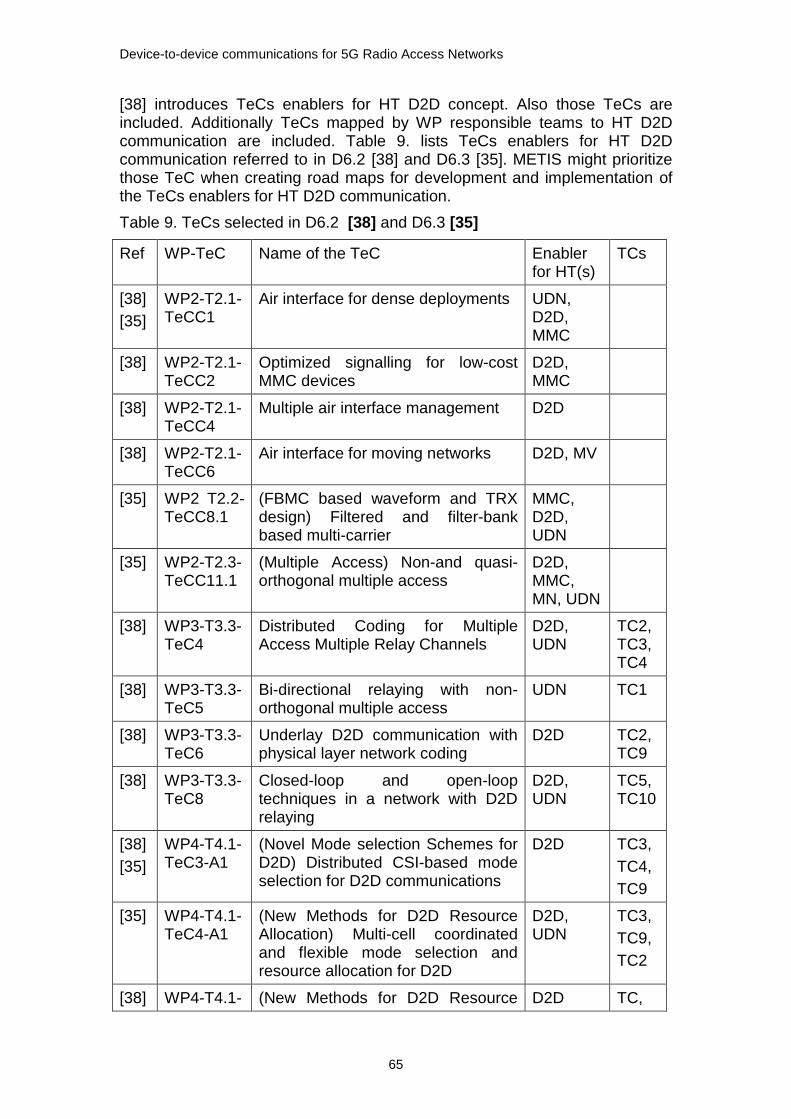
Device-to-device communications for 5G Radio Access Networks
65
[38] introduces TeCs enablers for HT D2D concept. Also those TeCs are included. Additionally TeCs mapped by WP responsible teams to HT D2D communication are included. Table 9. lists TeCs enablers for HT D2D communication referred to in D6.2 [38] and D6.3 [35]. METIS might prioritize those TeC when creating road maps for development and implementation of the TeCs enablers for HT D2D communication.
Table 9. TeCs selected in D6.2 [38] and D6.3 [35]
Ref WP-TeC Name of the TeC Enabler for HT(s)
TCs
[38]
[35]
WP2-T2.1-TeCC1
Air interface for dense deployments UDN, D2D, MMC
[38] WP2-T2.1-TeCC2
Optimized signalling for low-cost MMC devices
D2D, MMC
[38] WP2-T2.1-TeCC4
Multiple air interface management D2D
[38] WP2-T2.1-TeCC6
Air interface for moving networks D2D, MV
[35] WP2 T2.2-TeCC8.1
(FBMC based waveform and TRX design) Filtered and filter-bank based multi-carrier
MMC, D2D, UDN
[35] WP2-T2.3-TeCC11.1
(Multiple Access) Non-and quasi-orthogonal multiple access
D2D, MMC, MN, UDN
[38] WP3-T3.3-TeC4
Distributed Coding for Multiple Access Multiple Relay Channels
D2D, UDN
TC2,TC3,TC4
[38] WP3-T3.3-TeC5
Bi-directional relaying with non-orthogonal multiple access
UDN TC1
[38] WP3-T3.3-TeC6
Underlay D2D communication with physical layer network coding
D2D TC2,TC9
[38] WP3-T3.3-TeC8
Closed-loop and open-loop techniques in a network with D2D relaying
D2D, UDN
TC5,TC10
[38]
[35]
WP4-T4.1-TeC3-A1
(Novel Mode selection Schemes for D2D) Distributed CSI-based mode selection for D2D communications
D2D TC3,
TC4,
TC9
[35] WP4-T4.1-TeC4-A1
(New Methods for D2D Resource Allocation) Multi-cell coordinated and flexible mode selection and resource allocation for D2D
D2D, UDN
TC3,
TC9,
TC2
[38] WP4-T4.1- (New Methods for D2D Resource D2D TC,

Device-to-device communications for 5G Radio Access Networks
66
[35]
TeC-A1 and TeC15
Allocation) Further ICIC in D2D enabled HetNets
TC,
TC2
[35] WP4-T4.1-TeC6-A1
(Centralized schemes for interference management in UDN) Smart resource allocation in a UDN scenario – legacy network models 1)
D2D, UDN
TC2
[35] WP5-TeC14
Spectrum sharing and mode selection for overlay D2D communication
D2D
1) In D4.1 [45] and D4.2 [49] TeC T4.1 TeC6-A1 is known as Coordinated fast UL and DL resource allocation in UDN
5.7.1 HT D2D CONCEPT
According to the METIS methodology the HT concept is built by integrating relevant TeCs from different WPs to each HT. The HT concept then comprises new functionalities. Each HT concept is described in detail and common parts are identified. Common parts are taken into account when HTs will be integrated towards the overall METIS system concept. The path from METIS test cases to the final solution that will be provided for each test case, starts from HT concepts building an overall system concept. Currently we are in the Intermediate METIS 5G system concept phase, and approaching towards the METIS 5G system concept and solutions for METIS test cases [35]. HT D2D concept is depicted in Figure 42. The HT D2D concept consists of Device discovery, Communication mode selection, Resource allocation, Interference management, Power control, Flexible TDD air interface for D2D, Relay, D2D relay and Relayed D2D [38] .

Device-to-device communications for 5G Radio Access Networks
67
Figure 42. The initial high level proposal for HT D2D concept [38]
5.7.2 FLEXIBLE TDD AIR INTERFACE FOR D2D
The proposal for a flexible air interface is the use of different configurations. Actual system conditions and service requests will direct the selection of configurations to be used in mode of operation in question. The best configuration for the purpose will be selected based on the defined metrics, and the configuration is changed based on parameter values. As a result there will be a set of different configurations for different modes of operations.
TeCs are additionally enablers for HT UDN and HT MMC.
WP2-T2.1-TeCC1 Unified air interface design for dense deployments [38] , [35]
TeC1: Frame structure (including multi-antenna and beam-forming)
TeC2: Dynamic TDD
TeC3: Harmonized OFDM / PHY layer numerology
Research covers scalable frame structure which allows to adapt framing times and symbol durations, and it enables cost-efficient local communication. Dynamic partitioning of UL/DL periods in TDD mode will support the highly asymmetric traffic expected in UDN. Scalable frame structure gives flexibility and has short PHY layer latency [41].
Frame structure (TeC1) has two D2D communication enabling topics; Fast network synchronization and Extension to D2D and efficient device discovery.
Fast network synchronization.
A synchronization signal is embedded, for example by eNB or AP, in to the control part of each frame. This enables fast network synchronization by the network devices. This is a useful property also for D2D and MMC scenarios.
Extension to D2D and efficient device discovery.
Flexible OFDM-based waveforms can be applied for D2D communication to reduce the asynchronous in-band interference between D2D and cellular communications. Flexible OFDM-based waveforms like zero-tail DFT-S-OFDM. Utilizing the flexible OFDM-based waveforms enables switching of link direction on OFDM symbol level together with advanced Tx/Rx patterns and with the enabled fast network synchronization time, the frame structure can be extended to support very short discovery activity time (leading to lower energy consumption) for high number of devices. With this frame structure more than 50 times increase can be achieved compared to what is achievable with LTE-A frame structure [42].
WP2-T2.1-TeCC2: Optimized signalling for low-cost MMC devices [38]
Optimized signalling structures are developed for machine type of communication, for low cost and low power UEs with rather small data packages.
WP2-T2.1-TeCC4: Multiple air interface management [38]
A set of different configurations for different modes of operation is provided, allowing the air interface to be individually configured according to actual system conditions and service requests [42].
WP2-T2.1-TeCC6: Air interface for moving networks [38]
Device-to-device communications for 5G Radio Access Networks
68
Air interface design takes into account the requirements for vehicular-to-X (V2X) based communication. It includes road safety applications with strict reliability constraints.
WP2-T2.2-TeCC8: Filtered and filter-bank based multi-carrier [35]
TeCC8.1: Filter-bank based multi-carrier, FBMC, based waveform and transceiver design
The use of pulse shapes with good energy localization in frequency domain enable partitioning the spectrum into independent bands with relaxed requirements for synchronization. Thus, these waveforms are promising enablers for efficient spectrum sharing, in particular for the access to fragmented bands. It enables high robustness against Doppler and synchronization errors [41].
WP2-T2.3-TeCC11: Multiple Access (MA) [35]
T2.3 TeCC11.1: Non- and quasi-orthogonal multiple access
MAC approaches for contention or reservation based access of a large number of devices with low overhead. Depending on the application requirements users may either transmit whenever they have data by using a random access channel or reserve resources with efficient access reservation. A promising technique in random access to resolve potential collision with low signalling is a combination of coded random access and compressive sensing multi-user detection, which exploits the sporadic access of MMC nodes.
5.7.3 D2D DEVICE DISCOVERY AND COMMUNICATION MODE
SELECTION
For direct D2D communication to take place device discovery is needed. Network assisted device discovery is used to determine the vicinity between the devices, and the possibility to establish a direct D2D link. As an assumption dedicated resources are reserved for device discovery [45]. WP4 Multi-RAT/multi-layer networks include TeCs for device discovery. In METIS interim phase no TeCs for enabling device discovery have been selected as the most promising TeCs for further study [35].
WP4-T4.1-TeC2: Unified Solution for Device Discovery [45] or Unified resource allocation framework for D2D discovery [49] [38]
The TeC2 assumes that dedicated resources are available for the purpose of device discovery. TeC2 covers device discovery for both network coverage and out of network coverage scenarios. Assumption is that dedicated discovery resources available for cellular UL resources. UEs in the same cell are synchronized. Half-duplex communication, i.e., UEs cannot listen while transmitting. Both connected and idle UEs can discover each other [45]. System model is shown in Figure 43.

Device-to-device communications for 5G Radio Access Networks
69
Figure 43. System model for Device discovery [45]
Device discovery under network coverage and out of network coverage will have the same predefined steps. When device discovery takes place under networks coverage, eNBs manage the discovery resource management in a totally or a semi or a fully decentralized way. When device discovery takes place out of network coverage, discovery resources are managed either by Cluster Heads or in a device-centric manner. Cluster Head nodes are selected by electing. In a device-centric approach device discovery is done in a totally autonomous way. All devices have the same capability for device discovery and only ‘best effort’ type of service is provided. Discovery probability is used for selecting between centralized or decentralized way [49].
WP4-T4.1-TeC3: Novel mode selection schemes for D2D has two approaches. The first is T4.1-TeC3-A1: Distributed Channel State Information based Mode Selection for D2D communications, and the second is T4.1-TeC3A-2: Location-base mode selection for D2D.
WP4-T4.1-TeC3-A1: Distributed CSI-based mode selection for D2D communications [39] [35]
System model for T4.1-TeC3-A1: Distributed CSI-based mode selection for D2D communications is shown in Figure 44.
Observations show that mode selection and management of resources between D2D and cellular layers are tightly tied together. This TeC proposes the following three possible communication modes [45], [49]:
1. Cellular mode. This is the traditional communication mode via the cellular BS.
2. Direct mode without dedicated D2D resources. In this mode dedicated resources can be used when the UEs are in the proximity of one another.
3. Direct mode with cellular resource reuse.
Two algorithms, Cellular Protection Algorithm (CPA) and Balanced Random Allocation (BRA), are available [49]. BRA algorithm utilizes the available resources adaptively to the load in the cellular and D2D layer. CPA algorithm protects the cellular layer from the interference caused by the D2D layer.

Device-to-device communications for 5G Radio Access Networks
70
Figure 44. System model Distributed CSI mode selection for D2D [45]
D2D and cellular links are multiplexed on the same UL OFDM Physical Resource Block (PRB). At most one Cellular UE (CUE) can be allocated on PRB, and at most one D2D link is allocated to one PRB used by a CUE. This means that for any one PRB, there are at most two links, one cellular and one D2D. There is an algorithm used for mode selection based on information that is specific to the D2D pair. The algorithm requires large scale fading between the D2D Tx and D2D Rx (g2 in Figure 44.), and between the D2D Tx and the BS (g3 in Figure 44.). The algorithm first calculated hypothetical SNR values each link. This hypothetical capacity value is used for mode selection [45].
WP4-T4.1-TeC3-A2: Location-based mode selection [45]
The communication mode is selected based on the location information of the users. System model for location based mode selection is shown in Figure 45. BS decides based on distance and path loss estimation whether the D2D candidates can transmit in D2D mode or cellular mode. The D2D mode is selected only if it is beneficial from the users’ point of view [45] [49]. D2D pairs and CUEs are sharing either UL or DL PRB. Intra-cell orthogonality is maintained between CUEs. This means CUEs use different PRBs. Multiple D2D links can be scheduled at the same cellular Resource Block. FDD operation is assumed.
Figure 45. Location based mode selection [45] The main idea is that the BS uses UEs' location information when estimating the distance between the candidate D2D pair and between each of the candidate UEs and the BS. Distance information is mapped to corresponding received signal powers by using appropriate path loss model. BS decided the

Device-to-device communications for 5G Radio Access Networks
71
transmission mode (direct link or via BS) based on the distance and the path loss estimation. Direct link can be chosen if the distance between the users is smaller than the distance between any of the users and BS, and the distance is additionally smaller than a predefined arbitrary distance limit. After that base station searches for resources to be shared with the D2D link [45] [49].
WP5-TeC14: Spectrum sharing and mode selection for overlay D2D communication [37]
Mode selection can also base on spectrum sharing. More about TeC14can be found in chapter 5.7.9.
5.7.4 INTERFERENCE MANAGEMENT
WP3-T3.2-TeC11: Decentralized interference aware scheduling [50] [51]
The system model for the TeC11 is shown in Figure 46. It is assumed that the
system is a TDD system. D2D links are distributed on an area with uniform
distribution of node locations and a certain distribution of link distances. Multi-
antenna users are assumed. Initially D2D communication uses a separate
frequency band other than infrastructure based communication is considered.
If infrastructure based communication is included (co-channel and cellular
mode communication), multi-antenna BSs serving different users are
considered. This scheme is an alternative for classical Coordinated Multi-Point
(CoMP) use.
Figure 46. System model for Decentralized interference aware scheduling [50]
The work proposes a decentralized interference aware scheduling approach, which bases on the transmission of a reverse beacon. This beacon is broadcast from the destination node to surrounding sources, with information that describes e.g. the received desired signal level, the received interference-noise level and the average throughput of the node. In particular, the work focuses on the implementation in the Txs of schedulers that update the frame in which transmission is scheduled.
WP4-T4.1-TeC6: Centralized schemes for interference management in UDN [35] or Smart resource allocation in a UDN scenario –legacy network modes
The approach in interference management is to manage interference between marco cell and under laying small cells. A small cell uses flexible UL and DL switching and centralized scheduling. As a baseline is fixed UL and DL, and predefined UL and DL ratio shall be defined for different traffic requirements for decentralized scheduling.

Device-to-device communications for 5G Radio Access Networks
72
5.7.5 RESOURCE ALLOCATION
Radio Resource Management (RRM)
WP2 Deliverable D2.3 [42] presents Radio link enablers for RRM. WP2 presents a RRM algorithm for D2D communications that uses CSI.
Figure 47. Signaling scheme for D2D communication with full CSI [42]
A RRM algorithm for D2D communications that uses CSI of the overall cellular and D2D links is proposed, when CSI is available at BS side. With CSI BS can allocate radio resources to be shared with cellular users and D2D links. D2D pairs try to reuse cellular UL spectrum.
An efficient singling scheme is proposed with two options. The first one, shown in Figure 47., is signalling scenario with full CSI and the other scenario is signalling with partial CSI. With full CSI there will be heavy signalling overhead, and thus large latency to set up D2D communication. This option is not usable as D2D communication scenario requires low latency. The second option, shown in Figure 48., with partial CSI is more suitable for D2D communication scenarios.

Device-to-device communications for 5G Radio Access Networks
73
Figure 48. Signaling scheme for D2D communication with partial CSI [42]
WP4-T4.1-TeC4: New methods for D2D Resource Allocation [45]
Resource allocation in direct D2D communication takes place after mode selection. Resources for D2D communication can be either dedicated resources for D2D communication or the best cellular candidate to share resources with the D2D pair.
WP4-T4.1-TeC15 (or WP4-T4.1-TeC4-A1) Further enhanced ICIC for
enabling D2D in heterogeneous networks
4.1-TeC4-A2 Multi-cell coordinated and flexible resource allocation for
D2D in D4.1 [45] is recalled to T4.1-TeC4-A1 Multi-cell coordinated and
flexible mode selection and resource allocation for D2D in D4.2 [49].
WP4-T4.1-TeC15 (or WP4-T4.1-TeC4-A1) Further enhanced ICIC for enabling D2D in heterogeneous networks [38], [35]
System model for WP4-T4.1-TeC15 (or T4.1-TeC4-A1) Further enhanced ICIC for enabling D2D in heterogeneous networks is shown in Figure 49. System model is for heterogeneous network where D2D links are using the cellular DL resources. Macro layer resources are partially muted in the time domain (TDM eICIC) or alternatively in the frequency domain.
The main idea is to use interference measurements to schedule D2D links in muted macro cell sub-frames. D2D pairs or clusters (under the same macro cell) can use the muted resources of a macro cell, if no SC transmission detected. This is done by enhancing the current ICIC scheme. D2D links are scheduled in muted macro cell sub-frames based on interference measurements. UEs of a D2D pair measure e.g. Received Signal Strength Indicator (RSSI) during muted sub-frames of the controlling marco BS. The D2D pair can use the muted resources for their communication, if no strong small call is detected nearby. Otherwise unmuted resources are used [45].

Device-to-device communications for 5G Radio Access Networks
74
Figure 49. System model for Further enhanced ICIC for enabling D2D in heterogeneous networks [45]
TeCs for interference management are processed in WP4 Multi-RAT/multi-layer networks and in TeCs T4.1-TeC1 and T4.1-TeC6.
WP4-T4.1-TeC4-A1: Multi-cell coordinated and flexible mode selection and resource allocation for D2D
System model is mixed cellular and D2D communications. eNB or a coordinator node perform the resource allocation. D2D receiver and eNB use MIMO Interference Rejection Combining (IRC)/MMSE receiver. The D2D pair communicates over a bidirectional channel operating in TDD mode [45].
The solution is optimization of overall system performance and efficiency of a system with both cellular transmission and network-facilitated D2D.
WP3-T3.3-TeC2 Interference aware routing and resource allocation for access and backhaul [50] [51]
System model for the TeC is shown in Figure 50. A building with a multi-hop wireless backhaul and with multiple access nodes (AN), and the access links are sharing the same spectrum.
Figure 50. System model for Interference aware routing and resource allocation for access and backhaul TeC2 [50]
For enhancing the spectrum efficiency, the idea is to share the same spectrum among the wireless backhaul and the wireless access. The purpose is to investigate low complexity sub-optimal algorithms for sharing and coordinating the resources among the backhaul and the access network.
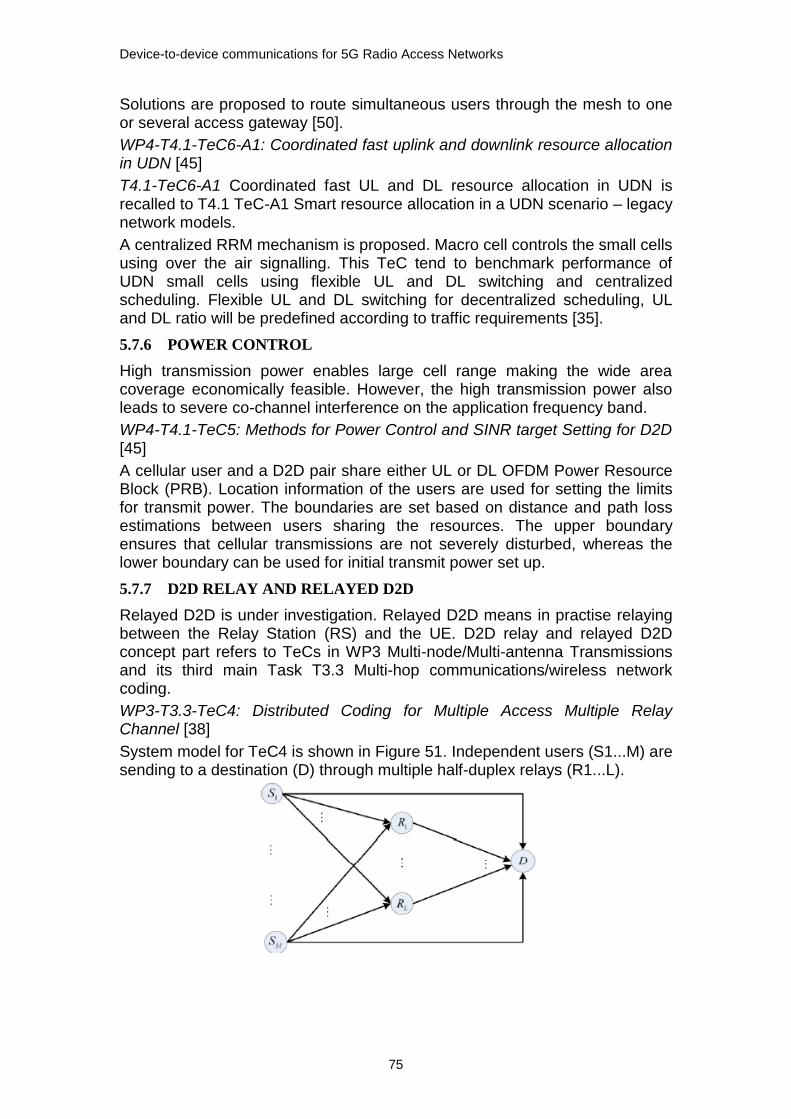
Device-to-device communications for 5G Radio Access Networks
75
Solutions are proposed to route simultaneous users through the mesh to one or several access gateway [50].
WP4-T4.1-TeC6-A1: Coordinated fast uplink and downlink resource allocation in UDN [45]
T4.1-TeC6-A1 Coordinated fast UL and DL resource allocation in UDN is recalled to T4.1 TeC-A1 Smart resource allocation in a UDN scenario – legacy network models.
A centralized RRM mechanism is proposed. Macro cell controls the small cells using over the air signalling. This TeC tend to benchmark performance of UDN small cells using flexible UL and DL switching and centralized scheduling. Flexible UL and DL switching for decentralized scheduling, UL and DL ratio will be predefined according to traffic requirements [35].
5.7.6 POWER CONTROL
High transmission power enables large cell range making the wide area coverage economically feasible. However, the high transmission power also leads to severe co-channel interference on the application frequency band.
WP4-T4.1-TeC5: Methods for Power Control and SINR target Setting for D2D [45]
A cellular user and a D2D pair share either UL or DL OFDM Power Resource Block (PRB). Location information of the users are used for setting the limits for transmit power. The boundaries are set based on distance and path loss estimations between users sharing the resources. The upper boundary ensures that cellular transmissions are not severely disturbed, whereas the lower boundary can be used for initial transmit power set up.
5.7.7 D2D RELAY AND RELAYED D2D
Relayed D2D is under investigation. Relayed D2D means in practise relaying between the Relay Station (RS) and the UE. D2D relay and relayed D2D concept part refers to TeCs in WP3 Multi-node/Multi-antenna Transmissions and its third main Task T3.3 Multi-hop communications/wireless network coding.
WP3-T3.3-TeC4: Distributed Coding for Multiple Access Multiple Relay Channel [38]
System model for TeC4 is shown in Figure 51. Independent users (S1...M) are sending to a destination (D) through multiple half-duplex relays (R1...L).
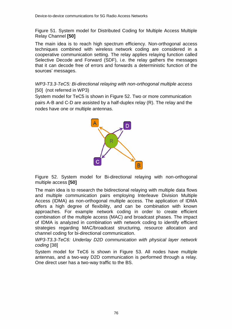
Device-to-device communications for 5G Radio Access Networks
76
Figure 51. System model for Distributed Coding for Multiple Access Multiple Relay Channel [50]
The main idea is to reach high spectrum efficiency. Non-orthogonal access techniques combined with wireless network coding are considered in a cooperative communication setting. The relay applies relaying function called Selective Decode and Forward (SDF), i.e. the relay gathers the messages that it can decode free of errors and forwards a deterministic function of the sources’ messages.
WP3-T3.3-TeC5: Bi-directional relaying with non-orthogonal multiple access
[50] (not referred in WP3)
System model for TeC5 is shown in Figure 52. Two or more communication
pairs A-B and C-D are assisted by a half-duplex relay (R). The relay and the
nodes have one or multiple antennas.
Figure 52. System model for Bi-directional relaying with non-orthogonal multiple access [50]
The main idea is to research the bidirectional relaying with multiple data flows and multiple communication pairs employing Interleave Division Multiple Access (IDMA) as non-orthogonal multiple access. The application of IDMA offers a high degree of flexibility, and can be combination with known approaches. For example network coding in order to create efficient combination of the multiple access (MAC) and broadcast phases. The impact of IDMA is analyzed in combination with network coding to identify efficient strategies regarding MAC/broadcast structuring, resource allocation and channel coding for bi-directional communication.
WP3-T3.3-TeC6: Underlay D2D communication with physical layer network coding [38]
System model for TeC6 is shown in Figure 53. All nodes have multiple antennas, and a two-way D2D communication is performed through a relay. One direct user has a two-way traffic to the BS.

Device-to-device communications for 5G Radio Access Networks
77
Figure 53. System model Underlay D2D communication with PHY layer network coding TeC6 [50]
The main idea is to develop multiple antenna techniques at the transmitting or receiving nodes to ensure coexistence of D2D and cellular communications in the same spectrum. The RN uses PHY layer network coding to bring high spectrum efficiency. The transmission has two phases. During the first transmission phase, the two relayed devices and the BS transmit simultaneously. During a second transmission phase, the relay broadcasts the network coded messages while the direct user transmits to the BS. In both phases to suppress the mutual interference caused by those simultaneous transmissions, Minimum Mean Square Error (MMSE) pre/decoders are used at all nodes.
WP3-T3.3-TeC8: Closed-loop and open-loop techniques in a network with D2D relaying [38]
System model for TeC8 is shown in Figure 54. TeC8 is enabler for HT D2D and HT UDN. System model presents communication from a multi-antenna BS to a multi-antenna destination user, where multi-antenna users assisting by acting as RNs. The dashed line shows the target logical connection between the source and the destination.
Figure 54. System model for Closed-loop and open-loop techniques in a network with D2D relaying [50]
A group of user terminals relay multiple streams to an out-of-reach user. All the nodes are equipped with multiple antennas. The work focuses on practical limitation of a user terminal when it is use as relays:
a) no cooperation among UEs,
b) CSI unavailability at the UE inducing, open-loop transmission for D2D relaying, such as space-time coding and directional beam forming,
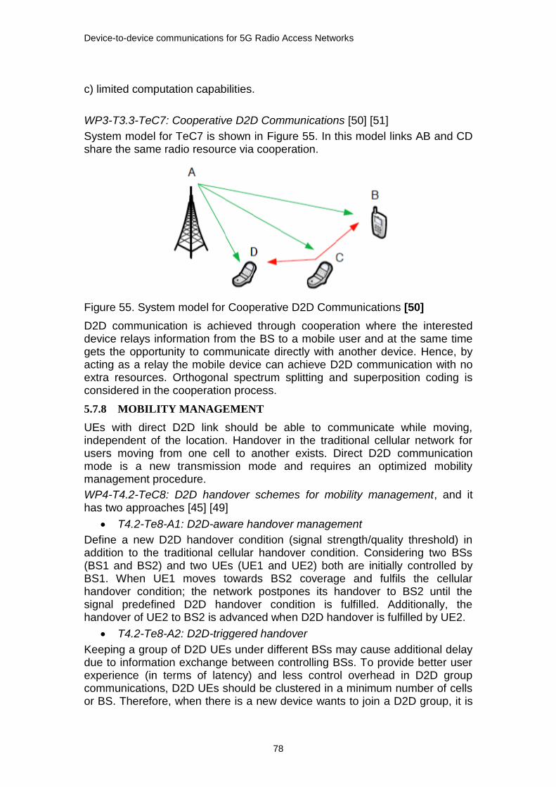
Device-to-device communications for 5G Radio Access Networks
78
c) limited computation capabilities.
WP3-T3.3-TeC7: Cooperative D2D Communications [50] [51]
System model for TeC7 is shown in Figure 55. In this model links AB and CD share the same radio resource via cooperation.
Figure 55. System model for Cooperative D2D Communications [50]
D2D communication is achieved through cooperation where the interested device relays information from the BS to a mobile user and at the same time gets the opportunity to communicate directly with another device. Hence, by acting as a relay the mobile device can achieve D2D communication with no extra resources. Orthogonal spectrum splitting and superposition coding is considered in the cooperation process.
5.7.8 MOBILITY MANAGEMENT
UEs with direct D2D link should be able to communicate while moving, independent of the location. Handover in the traditional cellular network for users moving from one cell to another exists. Direct D2D communication mode is a new transmission mode and requires an optimized mobility management procedure.
WP4-T4.2-TeC8: D2D handover schemes for mobility management, and it has two approaches [45] [49]
T4.2-Te8-A1: D2D-aware handover management
Define a new D2D handover condition (signal strength/quality threshold) in addition to the traditional cellular handover condition. Considering two BSs (BS1 and BS2) and two UEs (UE1 and UE2) both are initially controlled by BS1. When UE1 moves towards BS2 coverage and fulfils the cellular handover condition; the network postpones its handover to BS2 until the signal predefined D2D handover condition is fulfilled. Additionally, the handover of UE2 to BS2 is advanced when D2D handover is fulfilled by UE2.
T4.2-Te8-A2: D2D-triggered handover
Keeping a group of D2D UEs under different BSs may cause additional delay due to information exchange between controlling BSs. To provide better user experience (in terms of latency) and less control overhead in D2D group communications, D2D UEs should be clustered in a minimum number of cells or BS. Therefore, when there is a new device wants to join a D2D group, it is
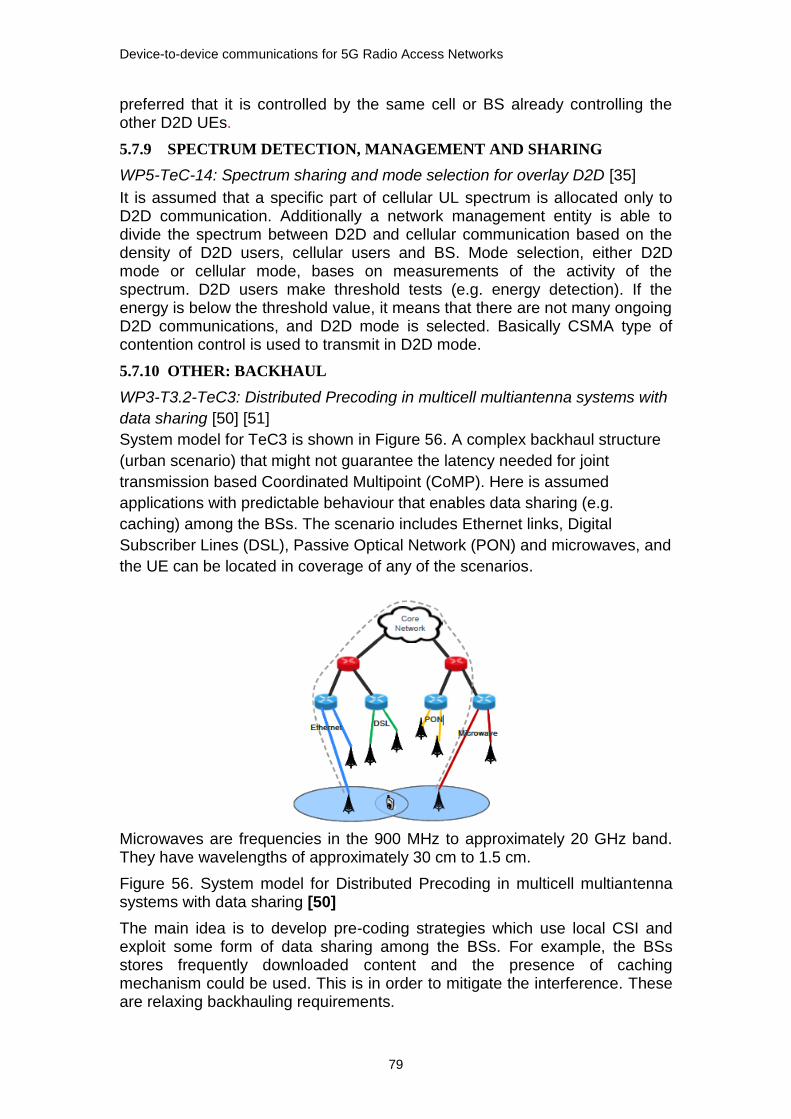
Device-to-device communications for 5G Radio Access Networks
79
preferred that it is controlled by the same cell or BS already controlling the other D2D UEs.
5.7.9 SPECTRUM DETECTION, MANAGEMENT AND SHARING
WP5-TeC-14: Spectrum sharing and mode selection for overlay D2D [35]
It is assumed that a specific part of cellular UL spectrum is allocated only to D2D communication. Additionally a network management entity is able to divide the spectrum between D2D and cellular communication based on the density of D2D users, cellular users and BS. Mode selection, either D2D mode or cellular mode, bases on measurements of the activity of the spectrum. D2D users make threshold tests (e.g. energy detection). If the energy is below the threshold value, it means that there are not many ongoing D2D communications, and D2D mode is selected. Basically CSMA type of contention control is used to transmit in D2D mode.
5.7.10 OTHER: BACKHAUL
WP3-T3.2-TeC3: Distributed Precoding in multicell multiantenna systems with
data sharing [50] [51]
System model for TeC3 is shown in Figure 56. A complex backhaul structure
(urban scenario) that might not guarantee the latency needed for joint
transmission based Coordinated Multipoint (CoMP). Here is assumed
applications with predictable behaviour that enables data sharing (e.g.
caching) among the BSs. The scenario includes Ethernet links, Digital
Subscriber Lines (DSL), Passive Optical Network (PON) and microwaves, and
the UE can be located in coverage of any of the scenarios.
Microwaves are frequencies in the 900 MHz to approximately 20 GHz band. They have wavelengths of approximately 30 cm to 1.5 cm.
Figure 56. System model for Distributed Precoding in multicell multiantenna systems with data sharing [50]
The main idea is to develop pre-coding strategies which use local CSI and exploit some form of data sharing among the BSs. For example, the BSs stores frequently downloaded content and the presence of caching mechanism could be used. This is in order to mitigate the interference. These are relaxing backhauling requirements.
Device-to-device communications for 5G Radio Access Networks
80
5.7.11 D2D IN INTERMEDIATE SYSTEM CONCEPT AND SYSTEM
ARCHITEHTURE
Intermediate system concept
The target of the METIS project is to develop the METIS 5G system concept that meets the METIS goals. First the HT concepts are specific and additional complementary TeCs developed, and then they are integrated into an overall system concept [39]. Flexibility, scalability and service-oriented management are the main drivers for METIS 5G architecture. [35]. For achieving the architecture the specific HT concepts are integrated with the METIS architecture [35].
In METIS Deliverable D6.3 [35] Direct D2D Communication has been divided into following sub-topics:
D2D-N for Non-critical applications, e.g. traffic offloading in Mobile Broadband (MBB) -type use-cases.
D2D-C for Critical/ultra-reliable applications, e.g. V2X communication, where fast establishment of the links and ultra-reliable communication of low to moderate amounts of data with very low latency is the dimensioning factor.
D2D-M for direct Machine-to-Machine (M2M) communication in MMC-M applications. Here, the protocol overhead is more important than latency, and the established links can be valid for longer time.
D2D-B for Backhaul applications to provide in-band self-backhaul in multi-hop mesh networks in UDN deployments.
METIS D6.3 [35] has identified three main fundamental services, and HTs are combined into a set of fundamental services. The main fundamental services are based on contributions / support from different HT sub-topics and they are:
Extreme/ advanced / flexible Mobile BroadBand (xMBB)
Massive Machine-Type Communication (M-MTC)
Ultra-reliable / Critical MTC (U-MTC)
For enabling the fundamental services METIS has defined the following key supporting functions:
Dynamic RAN
The spectrum toolbox
New lean signalling/control information
Localized content/traffic flows
Figure 57. shows how the HT sub-topics are mapped into the fundamental services. Only HT D2D communication has sub-topics depicted [35].

Device-to-device communications for 5G Radio Access Networks
81
Figure 57. HT D2D combined into a set of fundamental services
Intermediate system architecture
Preliminary conclusions of architectural analysis are described in D6.3 [35]. Building Blocks (BBs) are derived from the HT concept descriptions. BBs are used to show the overall functional architecture at high level. A BB in the architectural work addresses a collection of functionalities that are linked together providing higher level function (e.g. mobility management) [35]. The following three different kinds of BBs have been identified:
HT specific BBs
Common BBs
Frameworks for different purposes
Figure 58. illustrates the main BBs and functionalities for D2D communication. HT D2D specific BBs are D2D Device Discovery & Mode Selection in Radio Node Management, and MAC for D2D and D2D (Multi-Hop) in Air Interface Management.

Device-to-device communications for 5G Radio Access Networks
82
Figure 58. HT D2D and the main BBs
D2D communication specific BB in Radio Node Management is D2D Device Discovery & Mode Selection. Its function is to provide identification of local link opportunities and switching between different D2D modes. Different D2D modes are: underlay, overlay, out-of-band and D2D multi-hop.
D2D communication specific BBs in Air Interface are MAC for D2D and D2D (Multi-Hop). Building Block MAC for D2D means MAC and RRM functionalities at PHY layer. It means to synchronize devices in D2D mode. The other D2D specific BB is D2D (Multi-Hop). It means providing backhaul to the infrastructure via other devices and local D2D communication via third party devices. And additionally it means providing D2D communication via D2D relay.
METIS final report will publish D2D BB content in more details.

Device-to-device communications for 5G Radio Access Networks
83
6 RESULTS
In METIS HT D2D starts from WPs which are processed into Technology Components. Technical Components are mapped via test cases to HTs or directly to HTs. Additionally the most promising TeC, based on system simulations, have been selected for further study by D6.3. For the final 5G system concept HT specific concepts have been defined. HT D2D concept consists of:
Device discovery, Communication mode selection
Resource allocation
Interference management; advanced interference management
Power control; feedback information is used for CSI for power control
Spectrum detection/management/sharing for D2D usage
Mobility management
Flexible TDD air interface for D2D; a configurable air interface is
proposed to best meet D2D communication requirements
D2D relay, Relayed D2D
D6.2 selects some of the TeCs under HT D2D concepts, not necessary the most promising once but related to the concept area.
For METIS architecture development, HT concepts are defined with Building Blocks. BBs are used to show the overall functional architecture on high level. The high level METIS intermediate architecture consists of: Network Management, Radio Node Management and Air Interface. Network Management has no HT D2D specific BBs. Radio Node Management has HT D2D specific BB D2D Device Discovery and Mode Selection, and Air Interface has HT D2D specific BBs MAC for D2D and D2D (Multi-hop).
With METIS approach to D2D communication D2D is quite traceable. In the interim METIS phase, when the solutions for the test cases are not yet finalized, no road mapping or any features to 3GPP releases exist. The final METIS solutions for the test cases will be published on 30th April, 2015.
3GPP Release 12 has work items for ProSe or D2D. Completeness of TR and TS in study items are available on 3GPP web pages. So the schedule for availability and completeness of the study items are known to all parties.
The following lists on high level some D2D communication topics in 3GPP Release 12 and METIS project.
When comparing air interference management for D2D communication
METIS provides WP2-T2.1-TeCC1 Unified air interface design for dense deployments with three TeCs. 3GPP uses LTE air interface.
When comparing device discovery for D2D communication

Device-to-device communications for 5G Radio Access Networks
84
Device discovery is in scope of both 3GPP and METIS. 3GPP has reference model with reference points for device discovery. For device discovery 3GPP provides Model A (I am here) and Model B (Who is there/are you there). METIS provides WP4-T4.1-TeC2 Unified solution for device discovery or Unified resource allocation for D2D discovery.
When comparing ProSe or D2D management (mode selection and
resource management)
D2D modes are: Network mode, relay mode, ad hoc and cluster head modes. Both in 3GPP and in METIS C-plane is created between the D2D pair instead of C-plane creation via the base station and the UE. Modes for D2D communication are: cellular mode, direct mode with dedicated D2D resources and direct mode with cellular resource reuse. METIS provides TeCs with different approaches for mode selection (WP4.1-T4.1-TeC3, WP4.1-T4.1-TeC3-A1 and WP4.1-T4.1-TeC3-A2, WP5-TeC14). In 3GPP mode is selected based on the proximity which can be configured by the operator. When available, D2D communication will use the same resources as the cellular network.
When comparing scenarios or coverage communication
Both 3GPP and METIS have in-coverage (infrastructure based) and out-of-coverage (infrastructure less) D2D communication scenarios. In 3GPP out-of-coverage is only for public safety use cases, and relaying is used for out-of-coverage use cases. METIS provides in-coverage scenarios and multiple TeCs for relaying (WP3-T3.3-Te4, WP3-T3.3-Te5, WP3-T3.3-Te8). However, currently none of TeCs for relaying have been selected for further study.
When comparing D2D communication
Both 3GPP and METIS will provide one-to-one and one-to-many communication, but METIS currently without any schedule.
When comparing spectrum for D2D communication
METIS provides advanced and new ways for spectrum usage that are not in scope of any 3GPP release. And it is assumed that a specific part of cellular UL spectrum is allocated to D2D communication. WP5 provides a tool box for enhanced spectrum management. The tool box can be used for future new spectrum as well as for enhanced use of current spectrum. In 3GPP LTE and public safety specific spectrum is used.
When comparing charging and billing, and security for D2D
communication
3GPP has charging and billing, and security in scope. In METIS TeCs for HT D2D there is no mentioning of charging and billing, and security. METIS WPs provide multiple TeC for communication.
When comparing architecture for D2D communication
3GPP provides an architectural reference model with new network element or entity, ProSe Function, for enabling LTE based proximity services. METIS
Device-to-device communications for 5G Radio Access Networks
85
final architecture was published on 31st of Jan, 2015, and is not in scope of this thesis due to schedule limitations.
When comparing D2D communication for Public Safety
Associating the HT D2D communication with public safety can be done via TC10: Emergency communications. TC10 introduces an Emergency Mode where temporary nodes deployed for emergency management provide connectivity. In the Emergency Mode UEs may have additional functionality like acting as relays. TC10 concentrates on finding and saving victims with phones using Emergency Mode. KPIs for TC10 includes e.g. UEs shall be able to make 10 voice calls and send 10 SMS for one week per area of 10 square meters. TC10 expects also to support professionals working with the rescue operations.
For public safety 3GPP Rel-12 includes requirements retrieved from public safety use case and scenarios. Requirements are group communication, additional communication out-of-coverage using relay and enabling multimedia type of data from the disaster place to the persons responsible for organizing the rescue operations and wise versa. Current public safety standard, TETRA, only supports voice and data communication. Today requirements for multimedia transmission are evident. LTE shall support multimedia transmission but with some limitations. When he is out-of-coverage one user can send multimedia messages at a time. Group communication needed in emergency situations and have been added to 3GPP Rel-12.
According to 3GPP Release 12 public safety can use for ProSe discovery and communication ProSe specific spectrum and also use spectrum reserved for LTE coverag. METIS WP5 has analyzed the spectrum to discover new additional spectrum, and it provides spectrum usage proposals for each METIS test case.

Device-to-device communications for 5G Radio Access Networks
86
7 CONCLUSIONS
Currently LTE is missing direct communication between devices. 3GPP Rel-12 and METIS project include direct device-to-device communication but with different approaches. 3GPP has continuous releases on the 3GPP Release roadmap where as METIS is a project with the project specific schedule. 3GPP releases have specified content, i.e. selected features. METIS is a project with predefined project scope. METIS is researching new solutions for requirements beyond 2020. Both approaches are needed for developing a proper direct D2D communication concept.
3GPP Release 12 schedule is 30th March 2015, METIS final report will be published on 30th of April in 2015.
METIS has multiple TeCs enablers for HT D2D communication. It is quite easy to follow D2D in METIS project with a quite complicated methodology. Schedules for development and implementation of direct D2D communication capabilities will be published later.
3GPP Release 12 has ProSe work items in scope. However the structure of TRs and TSs with limited study is not very clear to me. So are all and right TRs and TSs includes. Additionally 3GPP Release 12 freeze date was in March, 2015, so the documents were updated, and due to my thesis schedule I was not able to follow the follow the very latest versions.
Scientific articles give good overviews of, for example, ProSe for public safety.
Proposals for further study
ProSe standardization work continues in 3GPP Release 13. Further study
could concentrate on ProSe services other than public safety.
D2D communication in METIS final reports, i.e. D2D communication e.g. in
5G architecture.
Public safety is in scope of both 3GPP Release 12 and 3GPP Release 12,
and METIS project. It would be interested to study how D2D
communication will be utilized for public safety and how it meets in 3GPP
releases and METIS project final report.
.

Device-to-device communications for 5G Radio Access Networks
87
REFERENCE
[1] NSN, White ja Paper, ”Looking ahead to 5G, NSN White Paper,” 2013, Dec.
[2] Ericsson, ”5G RADIO ACCESS, Ericsso Paper White,” 2013, Jun.
[3] 3GPP, ”3GPP Release 12,” 2015. Available: www.3gpp.org/specifications/releases/68-release-12. Referred: 8.2.2015.
[4] METIS, ”METIS project presentation, D8.3,” 2013, Apr.
[5] X. Lin, J. G. Andrews, A. Ghosh ja R. Ratasuk, ”An Overview on 3GPP Device-to-Device Proximity Services,” IEEE Communications Magazine, pp. 40-48, 2014, Apr.
[6] T. Doumi, M. Dolan, S. Tatesh, A. Casati, G. Tsirtsis, K. Anchan ja D. Flore, ”LTE for Public Safety Networks,” IEEE Communications Magazine, p. 106–112, Feb 2013.
[7] C. Hoymann, W. Chen, J. Montojo, A. Golitschenk, C. Koutsimanis ja X. Shen, ”Relaying Operations in 3GPP LTE: Challenges and Solutions,” 2013, Feb.
[8] J. Kurose ja K. W. Ross, ”Computer Networking,” Addison Wesley, 2010, pp. 523-557.
[9] IEEE, ”802.15.1, Part 15.1: Wireless Medium Access Control (MAC) and Physical Layer (PHY)”.
[10] IEEE, ”802.15.4, Part 15.4: Low-Rate Wireless Personal Area Networks (LR-WPANs),” 2011, Sep.
[11] IEEE, ”802.15.3, Part 15.3: Wireless Medium Access Control (MAC) and Physical Layer (PHY) Specifications for High Rate Wireless Personal Area Networks (WPANs),” 2003.
[12] IEEE, ”802.11: Wireless LAN Medium Access Control (MAC) and Physical Layer (PHY) Specification,” 2012, Feb.
[13] ETSI, ” TR 101 683 v1.1.1 Broadband Radio Access Networks (BRAN); HIPERLAN Type2; System Overview”.
[14] C. Huitema, ”Routing in the Internet,” Prentice Hall PTR, 1999, pp. 326-327.
[15] ETSI, ”TS 100 392-15 v1.4.1 Terrestrial Trunked Radio (TETRA); Voice plus Data (V+D); Part 15: TETRA frequency bands, duplex spacings and channel numbering,” 2010-3.
[16] ETSI, ” EN 300 396-1 v1.2.1 Terrestrial Trunked Radio (TETRA); Technical requirements for Direct Mode Operation (DMO); Part 1: General network design,” 2011-12.
[17] ELMAR, ”50th International Symposium, General System Architecture of TETRA Network for Public Safety Services,” 2008.
[18] TETRA, ”Introduction to TETRA Technology,” 2012. Available: www.qsl.net/kb9mwr/projects/voip/tetra. Referred: 30.11.2014.
[19] P25, ”Benefits_of_P25_Standards_v1_2013_09_24.pdf,” 2013 Sep. Available: www.project25.org/images/stories/ptis/docs/. Referred: 30.11.2014.
[20] P25, ”Home/Why P25?,” 2014. Available: www.codanradio.com/why-p25. Referred: 30.11.2014.
[21] 3GPP, ”Study on Proximity-based Services (Rel-12),” 2013.
[22] 3GPP, ”TR 23.703 v12.0.0, Study on architecture enhancements to support Proximity-based Services (ProSe)(Release 12),” 2014, Feb.
Device-to-device communications for 5G Radio Access Networks
88
[23] 3GPP, ”TS 22.278 v12.6.0, Service requirements for the Evolved Packet System (EPS)(Release 12),” 2014, Dec.
[24] 3GPP, ”Proximity-based Services (Rel-12),” 2013.
[25] 3GPP, ”Study on LTE Device-to-device Proximity Services - Radio Aspects,” 2013.
[26] 3GPP, ”Group Communication System Enablers for LTE,” 2014.
[27] 3GPP, ”TR 22.803 v12.2.0, Feasibility study for Proximity Services (ProSe)(Release 12),” 2013, Jun.
[28] 3GPP, ”3GPP TS 23.303 v12.2.0, Proximity-based services (ProSe); Stage 2 (Release 12),” 2014, Sep.
[29] 3GPP, ”TR 33.833 V1.0.0, Study on Security issues to support Proximity Services (ProSe) (Release 12),” 2014, Jun.
[30] 3GPP, ”TS 22.115 V12.2.0, Charging and billing (Release 12),” 2013, Sep.
[31] 3GGP, ”General Packet Radio Service (GPRS) enhancements for Evolved Universal Terrestrial Radio Access Network (E-UTRAN) access (Release 12),” 2014, Dec.
[32] 3GPP, ” TS 33.303 V12.2.0, Proximity-based Services (ProSe); Security aspects (Release 12),” 2014, Dec.
[33] 3GPP, ”TR 36.843, v12.0.1, Study on LTE Device to Device Proximity Services; Radio Aspects (Release 12),” 2014, Mar.
[34] 3GPP, ”TR 36.868 v.v.v, Evolved Universal Terrestrial Radio Access (E-UTRA); Study on group communication for E-UTRA (Release 12),” 2014, Mar.
[35] METIS, ”Intermediate system evaluation results, D6.3,” 2014, Jul.
[36] METIS, ”Scenarios, requirements and KPIs for 5G mobile and wireless system, D1.1,” 2013, Apr.
[37] METIS, ”Description of the spectrum needs and usage principles, D5.1,” 2013, Aug.
[38] METIS, ”Initial report on horizontal topics, first result and 5G system concept, D6.2,” 2014, Mar.
[39] METIS, ”Initial report on horizontal topics, first result and 5G system concept, D6.2 Summary,” 2014, Mar.
[40] METIS, ”Novel radio link concepts and state of the art analysis, D2.2,” 2013, Oct.
[41] METIS, ”Components of a new air interface – building blocks and performance, D2.3 Summary,” 2014, Apr.
[42] METIS, ”Components of a new air interface – building blocks and performance, D2.3,” 2014, Apr.
[43] A. Osseiran, V. Braun, T. Hidekazu, P. Marsch, H. Schotten, H. Tullberg, M. Uusitalo ja M. Schellmann, ”The foundation of the Mobile and Wireless Communications System for 2020 and beyond,” 2013.
[44] A. Damnjanovic, J. Montojo, Y. Wei, T. Ji, T. Luo, M. Vajapeyam, T. Yoo, O. Song ja D. Malladi, ”A Survey on 3GPP Heterogeneous Networks,” 2011, Jun.
[45] METIS, ”Summary on preliminary trade-off investigations and first set of potential network-level solutions, D4.1,” 2013, Oct.
[46] ITU_Radio_Regulations, ”Article 5, Frequency allocations,” 2014.

Device-to-device communications for 5G Radio Access Networks
89
[47] ECC_within_CEPT, ”THE EUROPEAN TABLE OF FREQUECY ALLOCATIONS AND APLICATIONS (ECA TABLE),” 2014, May.
[48] METIS, ”Description of the spectrum needs and usage principles, D5.3,” 2014, Aug.
[49] METIS, ”Final repport on trade-off investigations, D4.2,” 2014, Aug.
[50] METIS, ”Positioning of multi-node/multi-antenna transmission technologies, D3.1,” 2013, Jul.
[51] METIS, ”First performance results for multi-node/multi-antenna transmission technologies, D3.2,” 2014, Apr.
Device-to-device communications for 5G Radio Access Networks
90
A TECHNOLOGY COMPONENTS IN WP2
WP2 Radio Link Concept has processed 15 Technology Components. WP2
has Research Topics [40] which are recalled to TeCs and listed in D2.3 [42].
TeCC#1: Unified air interface design for dense deployments
UDN TDD frame numerology
METIS UDN optimized frame structure
Flexible TTI for eff. energy saving and high-speed transfer
TeCC#2: Optimized signaling for low-cost MMC devices
MMC-type D2D links
Hybrid access scheme for reduced signaling overhead
TeCC#3: Air interface supporting dynamic spectrum usage
RF architectures for multi-band operation
TeCC#4: Multiple air interface management
Multi-RAT PHY layer design & multi-band processing
Software configurable air interface
TeCC#5 Advanced signaling concepts
Signaling for non-orthog. multiple access
TeCC#6: Air interface for moving networks Framework for URC
URC framework for modelling and predicting link reliability
Channel estimation for V2V links
Channel predicition for the backhaul link
TeCC#7: Faster than Nyquist
TeCC#8: Filtered and filterbank based multi-carrier
TeCC#8.1: FBMC based waveform & transceiver design TeCC#8.2:
Universal filtered multi-carrier (UFMC)
TeCC#9: Modulation & coding and new channel coding concepts
TeCC#9.1: Constrained envelope coded modulation
TeCC#9.2: Advanced coding and decoding
o Adaptive complexity flexible baseband
o Practical lattice codes
TeCC#10: Advanced transceiver design
TeCC#10.1: Full duplex TRX
TeCC#10.2: Multi-rate equalizers for single carrier comm.
TeCC#11: Multiple access (MA)
TeCC#11.1: Non- & quasi-orthog. MA allowing spectrum overload
o Non-orthogonal multipe access (NOMA)
o UL SCMA random access

Device-to-device communications for 5G Radio Access Networks
91
TeCC#11.2: FBMC based multiple access and Cognitive Radio
o MA with Cognitive Radio
o Precoding & RX processing for MA MIMO FBMC
TeCC#12: Medium access control
TeCC#12.1: Contention based massive access
o Coded random access
o Coded access reservation
o Adv. PHY processing for enhanced MAC
TeCC#12.2: Distributed network synchronization
TeCC#12.3: MAC for UDN and mmW
TeCC#13: Hybrid automatic repeat request (HARQ)
Incremental Redundancy with backtrack retransmission
Mult-level ACK/NACK for reliability based HARQ
TeCC#14: Radio Link Enablers for RRM

Device-to-device communications for 5G Radio Access Networks
92
B TECHNOLOGY COMPONENTS IN WP3
WP3 T3.2 Research cluster 1 and its TeCs
TeC1: Multi-Node Resource Allocation under Imperfect Feedback and
Backhaul Channels
TeC2: CoMP feedback reduction and theoretical analysis of net DoF
with delayed CSIT
Tec3: Distributed Precoding in multicell multiantenna systems with
data sharing
WP3 T3.2 Research cluster 2 and its TeCs
TeC4: Alignment of Intra Cell Multi User and Inter Cell Interference in a
MU-MIMO Cellular Network
TeC5: Semi-distributed IA algorithm for MIMOIC channel, with power
control to speed up convergence
TeC6: Robust decentralized scheme for IA with convergence control
WP3 T3.2 Research cluster 3 and its TeCs
TeC7: Dynamic clustering with multiple receive antennas in downlink
CoMP systems
TeC8: Non-orthogonal multiple access (NOMA) with multi-antenna
nodes and multi-site extensions
TeC9: Coordination scheme for medium range interference with
message splitting to facilitate efficient SIC
TeC10: Joint linear downlink CoMP with enhanced signal processing at
the UEs and bounds for clustered JT
TeC11: Decentralized interference aware scheduling
TeC12: Network-assisted interference suppressing/cancelling receivers
and ultradense networks
TeC13: Extension of IMF-A interference mitigation framework to small
cell scenarios and Massive-MIMO
TeC14: Joint dynamic clustering and coordinated scheduling for
relaying with Physical Layer Network Coding
TeC15: Adaptive and energy efficient dense small cells coordination
TeC16: Non-coherent transmission schemes for practical inter-node
coordination systems
WP3 T3.3 Research cluster 1and its TeCs
TeC1: Coordinated multi-flow transmission for wireless backhaul

Device-to-device communications for 5G Radio Access Networks
93
TeC2: Interference aware routing and resource allocation for access
and backhaul
TeC3: Virtual Full-Duplex Buffer-Aided Relaying
TeC4: Distributed Coding for the Multiple Access Multiple Relay
Channel
TeC5: Bi-directional relaying with non-orthogonal multiple access
WP3 T3.3 Research cluster 2 and its TeCs
TeC6: Underlay D2D communication with physical layer network
coding
TeC7: Cooperative D2D Communications
TeC8: Closed-loop and open-loop techniques in a network with D2D
relaying
TeC9: Studies of deploying moving relay nodes
TeC10: Combining phy layer network coding and MIMO for TDD
wireless systems with relaying

Device-to-device communications for 5G Radio Access Networks
94
C TECHNOLOGY COMPONENTS IN WP4
Task T4.1 Co-existence, collaboration and interference management has the following TeCs:
WP4-T4.1 TeC1: New interference estimation technique.
WP4-T4.1 TeC2: Unified Solution for Device Discovery
WP4-T4.1 TeC3: Novel mode selection schemes for D2D
o T4.1 TeC3-A1Distributed CSI-based mode selection for D2D communications
WP4-T4.1 TeC4: New methods for D2D Resource Allocation
o T4.1TeC4-A1: Further enhanced ICIC for enabling D2D in heterogeneous networks
o T4.1 TeC4-A4: Multi-cell coordinated and flexible resource allocation for D2D
WP4-T4.1 TeC5: Methods for Power Control and SINR target Setting for D2D
WP4-T4.1 TeC6: Centralized schemes for interference management in UDN
o T4.1TeC6-A1 Smart resource allocation in a UDN scenario – legacy network models
WP4-T4.1 TeC7: Decentralized and hybrid Schemes for Interference Management in UDN
Task T4.2 Demand, traffic, and mobility management
TeC1: Optimized distribution scheme for context information between the network entities
TeC2: Context awareness through prediction of next cell
TeC3: Smart device/service to layer mapping in the Phantom cell concept
TeC4: Efficient Service to layer mapping and connectivity in UDN
TeC5: Efficient vertical RAT mapping through vertical handover
TeC6: Handover optimization using street-specific context information
TeC7: Context aware mobility handover optimization using Fuzzy Q-Learning
TeC8: D2D handover schemes for mobility management
TeC9: Smart mobility and resource allocation mapping using context information
TeC10: Signalling or trajectory prediction
Task T4.3 Functional Network enablers has the following TeCs [D4.2]

Device-to-device communications for 5G Radio Access Networks
95
T4.3-TeC1-A1 – New management interface between the operator and the service provider
T4.3-TeC1- A2: New management interfaces for information exchange and action enforcement
T4.3-TeC2 – Clustering Toolbox
T4.3-TeC3-A2 – Dynamic Nomadic Node Selection for Backhaul Optimization
T4.3-TeC4-A1 – Activation and deactivation of nomadic cells
T4.3-TeC4-A2 – Activation and Deactivation of small cells in UDN
T4.3-TeC5 – Self-management enabled by central database for energy savings in the Phantom Cell Concept (PCC)
T4.3-TeC6 – Framework for control/user plane design with over-the-air signalling for UDN

Device-to-device communications for 5G Radio Access Networks
96
D TECHNOLOGY COMPONENTS IN WP5
Spectrum related TeC Clustering
TeC cluster Spectrum management concept
TeC02 Flexible spectrum use for moving networks
TeC12 Spectrum opportunity detection and assessment
TeC16 Spectrum management implementation and integration
TeC17 Ontologies as tool for spectrum decision making
TeC cluster Coordinated spectrum sharing
TeC01 Algorithms enabling sharing in unlicensed bands
TeC04 Coordinated multi-carrier waveform based sharing technique
TeC05 Co-ordination protocol for interaction between operators
supporting the use of limited spectrum pool and mutual renting
TeC06 Geo-location based interference management in environments
with non-uniform user density and terrain-based propagation
TeC09 Inter-UDN coordinated spectrum sharing
TeC14 Spectrum sharing & mode selection for overlay D2D
communication
TeC18 Reinforcement learning scheme for adaptive spectrum sharing
TeC19 Base Station clustering for inter-operator spectrum sharing
under realistic network deployment
TeC20 Prepared and database assisted URC communication for V2V
TeC21 Physical cell ID allocation in inter-operator spectrum sharing
HetNets
Device-to-device communications for 5G Radio Access Networks
97
TeC cluster Research studies
TeC03 Inter-operator separation rule for non-cooperative spectrum
sharing
TeC07 Coexistence-aware resource allocation for extremely close
nodes
TeC08 Modelling aggregate interference from in-car BS to indoor
femto-cells
TeC15 Generic models and tools for coexistence evaluation