Embed Size (px)
Citation preview

HAL Id: hal-03020985https://hal.archives-ouvertes.fr/hal-03020985
Submitted on 19 Dec 2020
HAL is a multi-disciplinary open accessarchive for the deposit and dissemination of sci-entific research documents, whether they are pub-lished or not. The documents may come fromteaching and research institutions in France orabroad, or from public or private research centers.
L’archive ouverte pluridisciplinaire HAL, estdestinée au dépôt et à la diffusion de documentsscientifiques de niveau recherche, publiés ou non,émanant des établissements d’enseignement et derecherche français ou étrangers, des laboratoirespublics ou privés.
DEVELOPMENT OF “WHOLE” EVALUATIONALGORITHM OF THE CONTROL QUALITY OF
“CUPOLA -MIXER” MELTING DUPLEX PROCESSDmitriy Demin
To cite this version:Dmitriy Demin. DEVELOPMENT OF “WHOLE” EVALUATION ALGORITHM OF THE CON-TROL QUALITY OF “CUPOLA -MIXER” MELTING DUPLEX PROCESS. Technology audit andproduction reserves, PC Technology Center, 2019, �10.15587/2312-8372.2019.174449�. �hal-03020985�

METALLURGICAL TECHNOLOGY
4 TECHNOLOGY AUDIT AND PRODUCTION RESERVES — № 3/1(47), 2019
UDC 681.5:519.24:621.74 DOI: 10.15587/2312-8372.2019.174449
DEVELOPMENT OF «WHOLE» EVALUATION ALGORITHM OF THE CONTROL QUALITY OF «CUPOLA – MIXER» MELTING DUPLEX PROCESS
Об’єктом дослідження є управління дуплекс-процесом «вагранка – міксер», предметом дослідження – якість системи управління плавкою «в цілому». Під терміном «в цілому» розуміється, що оцінюються не окремі операції управління, а можливість діючої в цеху системи управління забезпечувати задані вимоги щодо якості чавуну.
Одним з найбільш проблемних місць є відсутність у керівного персоналу алгоритмів отримання об’єк-тивної інформації про якість управління дуплекс-процесами плавки. Це призводить до того, що не вдається отримати відповідь на питання, в якій саме ділянці або в який саме момент часу реалізації процесу допущені порушення в частині управління плавкою.
В ході дослідження використовувалися методи розрахунку вибіркових статистичних функцій, перевірки гіпотези про вид закону розподілу, регресійний аналіз, дисперсійний аналіз, методи теорії ймовірності. Дані методи були інтегровані в загальний алгоритм, названий алгоритмом оцінки «в цілому» якості управління дуплекс-процесом плавки.
Запропонований алгоритм дозволяє кількісно оцінити якість управління дуплекс-процесом за таким показником, як ймовірність отримання відхилень за хімічним складом. А також тривалість нестаціо-нарного режиму, яка відповідає часу стабілізації хімічного складу шляхом операцій управління процесом, передбаченого прийнятою в цеху системою управління.
Отримані результати апробації алгоритму дозволяють вважати його ефективним інструментом отримання об’єктивної інформації про якість управління дуплекс-процесом плавки «вагранка – міксер». Це пов’язано з тим, що коректність постановки і рішення задачі забезпечила отримання адекватних результатів. На відміну від існуючих емпіричних оцінок, запропонований алгоритм дозволяє розробляти варіанти удосконалення процесів управління. Як обґрунтування цього висновку запропоновано концеп-туальні варіанти технічної реалізації системи регулювання. Зокрема, запропонована проста схема регулятора, що забезпечує можливість підтримання сталості температури чавуну і продуктивності вагранки шляхом регулювання рівня холостої та металевої колош. Управління процесом в цьому випадку здійснюється шляхом подачі керуючих сигналів на виконавчі механізми шиберів бункера з коксом і мета-левою шихтою, що формуються системами ручного або автоматизованого управління.
Ключові слова: алгоритм оцінки «в цілому» якості управління, схема регулятора, вагранкова плавка, термочасова обробка, дуплекс-процес плавки «вагранка – міксер».
Demin D.
Copyright © 2019, Demin D.
This is an open access article under the CC BY license
(http://creativecommons.org/licenses/by/4.0)
Received date: 10.11.2018
Accepted date: 02.12.2018
Published date: 30.06.2019
1. Introduction
Metallurgical processes are among the complex ob-jects of control. This is due to the fact that there are uncertainties in assessing their state. The reasons for this are the complexity, and often the impossibility of measuring state variables, the multi-alternativeness in choosing the final state and quality control criteria, and often the conflict of such criteria. Significant difficul-ties are caused by the mathematical description of these processes, since obtaining an adequate description is as-sociated with the need to build mathematical models of the control object from a small data sample. Moreover, such data should be obtained directly in the course of
technological processes, since laboratory experiments are of little use, given the specifics of metallurgical processes and equipment.
Despite all these objective difficulties, the requirements for the quality of the products should be invariably ob-served, and taking into account their constant tightening. All this determines the relevance of research aimed at finding methods of mathematical description and optimal, according to the selected criteria, control of such pro-cesses. The task of assessing the quality of management, in accordance with the process control system adopted at a particular industrial enterprise, also falls into the scope of such a search. Among these processes is the duplex process «cupola – mixer». Despite the fact that this process is
INDUSTRIAL AND TECHNOLOGY SYSTEMS:METALLURGICAL TECHNOLOGY
5TECHNOLOGY AUDIT AND PRODUCTION RESERVES — № 3/1(47), 2019
ISSN 2226-3780
not among the widespread, its study is of interest from the point of view of solving a number of management problems. This is because the control of metallurgical processes in each of these furnaces requires the correct formulation and solution of problems at each stage of the search for optimal control. This also applies to as-sessing the initial state, and constructing a mathematical model, and the stage of describing the final state, and the choice of control in the conditions that occur in these types of furnaces:
– uncertainty in the estimation of heat and mass transfer parameters, heat and energy characteristics and physi-cochemical processes occurring in furnaces;– presence of a drift of process characteristics;– impossibility of measuring some state variables in real time;– significant inertia of metallurgical furnaces as control objects.Therefore, conducting research to overcome these listed
difficulties in any part of them should be considered relevant.
2. The object of research and its technological audit
2.1. The object of research and the scheme of the «cupola – mixer» melting duplex process. The object of research is the control of the «cupola – mixer» duplex process, the subject of research is the quality of the «whole» melting control system. The term «whole» will further be understood to mean that it is not individual control operations that are evaluated, but the ability of the control system operating in the workshop to provide specified requirements for the quality of cast iron.
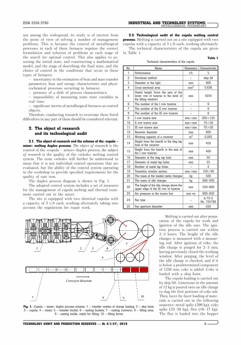
The duplex process diagram is shown in Fig. 1.The adopted control system includes a set of measures
for the management of cupola melting and thermal treat-ment carried out in the mixer.
The site is equipped with two identical cupolas with a capacity of 5 t/h each, working alternately taking into account the regulations for repair work.
2.2. Technological audit of the cupola melting control process. Melting is carried out on a site equipped with two cupolas with a capacity of 5 t/h each, working alternately.
The technical characteristics of the cupola are given in Table 1.
Table 1Technical characteristics of the cupola
No. Name Dimension Characteristic
1 Performance t/h 5
2 Download method – skip lift
3 Diameter in the light mm 900
4 Cross-sectional area mm2 0.636
5Useful height (from the axis of the lower row of tuyeres to the level of the filling window)
mm 4234
6 The number of the I row tuyeres – 6
7 The number of the II row tuyeres – 6
8 The number of the III row tuyeres – 6
9 I row tuyere size mm × mm 200 × 125
10 II row tuyere size mm × mm 70 × 50
11 III row tuyere size mm × mm 70 × 50
12 Receiver diameter mm 820
13 Working capacity of a receiver m3 0.283
14 Height from the hearth to the slag tap hole of the receiver mm 450
15 Height from the hearth to the axis of the I row tuyeres mm 400
16 Diameter of the slag tap hole mm 50
17 Diameter of metal tap holes mm 25
18 Number of metal tap holes – 2
19 Transition window section mm × mm 120 × 90
20 The mass of the loaded metal charges kg 500
21 The mass of idle charges kg 900–930
22 The height of the idle charge above the upper edge of the III row of tuyeres mm 550–600
23 Air pressure in the tuyere box mm wc 600–650
24 Fan type – А-72-2 No. 725766
25 Fan aperture diameter mm 220
Melting is carried out after prepa-ration of the cupola for work and ignition of the idle ears. The igni-tion process is carried out within 2–3 hours. The height of the idle charges is measured with a measur-ing rod. After ignition of coke, the idle charge is purged for 2–3 min, having previously closed the working window. After purging, the level of the idle charge is checked, and if it is below a predetermined component of 1250 mm, coke is added. Coke is loaded with a skip hoist.
The cupola loading is carried out by skip lift. Limestone in the amount of 12 kg is poured onto an idle charge to slag the first portions of coke ash. Then, layer-by-layer loading of mate-rials is carried out in the following sequence: metal spike (500 kg), coke spike (53–58 kg), flux (16–17 kg). The flux is loaded into the hopper
Fig. 1. «Cupola – mixer» duplex process scheme: 1 – transfer system of charge loading; 2 – skip hoist; 3 – cupola; 4 – mixer; 5 – transfer bucket; 6 – casting buckets; 7 – casting conveyor; 8 – filling area;
9 – casting molds, ready for filling; 10 – filling forms
INDUSTRIAL AND TECHNOLOGY SYSTEMS:METALLURGICAL TECHNOLOGY
6 TECHNOLOGY AUDIT AND PRODUCTION RESERVES — № 3/1(47), 2019
ISSN 2226-3780
of the weighing cart directly to the fuel spike, which is considered working. To avoid contact of limestone with the lining of the cupola, it is loaded into the central part of the hopper.
The components of the metal charge are loaded in the following order: cast iron, scrap iron, domestic waste, steel scrap. Ferrosilicon is loaded onto the very top of a metal charge.
The described loading procedure is considered control and corresponds to the normal mode of cupola operation.
After loading the charge to the level of the filling window and the necessary exposure for natural heating of the first metal charges for 15–20 min, the cupola is ready for melting. To start melting, the following opera-tions are performed:
1) one or two tuyere peepholes are opened to avoid an explosion when the blast is turned on;
2) the blast is turned on, its supply is controllers by the gate on the air duct (pressure should be 580–630 mm wc);
3) when the first portions of metal appear in the re- ceivers, the metal tap hole is sealed with a molding com-position.
During the smelting process, cast iron from the cu-pola is continuously supplied to the receiver, from which metal is delivered to the transfer ladles with a capacity of 2000 kg.
After each release of cast iron from the receiver, the metal tap hole is closed with a clay stopper. Approximately 15–20 minutes after starting the blasting, the slag runner for slag discharge closes and opens during the smelting process as necessary. First, the water supply to the gut-ter is switched on, through which the slag and water are sent to the receiving pit. When the slag comes in contact with water, it granulates. Granular slag from the pit is periodically removed by a grab. Each time the slag tap is opened, the blasting is temporarily disabled.
The molten slag, descending along the walls of the mine, meets cold air at the tuyeres, cools, thickens and settles on pieces of coke at the tuyeres. Thus, freezing of the slag occurs, which leads to a decrease in the live section of the tuyeres through which air enters the cupola shaft. At the same time, air consumption can decrease by 30–40 %, which leads to a decrease in cupola productivity and cast iron temperature.
Slagged tuyeres are cleaned through the tuyere ob-servation windows with a crowbar, pushing the slagged coke and growths into the cupola with short strokes. To more quickly eliminate slagging through the filling win-dows, fluorspar is poured into the center of the shaft in an amount of up to 5–6 kg.
The control of the cupola melting process is carried out in order to ensure the specified process indicators – state variables, which are the temperature and chemical composition of cast iron. In the management process, the following tasks are solved:
– elimination of freezing of the charge;– prevention of cold running cupola;– prevention of forced stops;– prevention of local heating of the casing;– preventing breakthrough of cast iron through under.Elimination of freezing of the charge. Hanging is elimi-
nated by scrap, introducing it into the charge through the filling window. If the freeze can’t be quickly elimi-nated, the supply of the blast stops. A large hang of the
charge leads to the burnout of the blank spike, therefore, after eliminating the hang, an additional fuel spike (coke transfer) is loaded into the cupola in the amount of up to 2–3 working coke spikes.
Cold cupola running. The main reason for the cold running of the cupola is the low height of the blank spike and its low-quality ignition before filling the charge. To eliminate the cold running, a working coke oven head (coke trans-fer) of 2–3 working coke heads is loaded into the cupola.
Forced stops. The reasons for such stops may be a shut-down of the foundry conveyor or equipment failure. In this case, to stop the cupola operation, the supply of blast is stopped, all the cast iron and slag are released, tuyeres are closed, the tap holes are closed with a fresh molding mixture to prevent air leaks and stop the coke burning.
Local heating of the casing. Local heating of the casing is visually determined through its local redness. Warming up occurs due to burnout or destruction of the lining in the high temperature zone, leading to the fact that hot gases or directly cast iron and slag come into contact with a metal casing. In order to avoid burn-through of the casing, a stream of water is directed to the heated place until the place of heating is darkened. After this, the cupola operation continues, since the cast iron that has penetrated to the casing.
Cast iron breakthrough the heart. The penetration of cast iron into the joint of the hearth with the lining occurs due to weak stuffing or stuffing with dry molding earth. In this case, a jet of water is directed to an overheated place, which is determined visually by its redness.
If a breakthrough of cast iron occurs through the bot-tom, the blasting stops and the cast iron is released. Clay is pressed into the hole formed as a result of the break-through and an additional layer of clay is applied outside, supported by a metal tile and propped up support.
The melting end time is determined depending on the need for liquid metal and the amount of unmelted metal in the cupola.
After loading the last spike, the amount of air sup-plied is kept constant, for which the gate on the air duct gradually closes.
The complete penetration of the charge is indicated by the cessation of the dripping of droplets of iron at the tuyeres. If this happens, then the blasting is stopped, the gate closes completely, and the lance eyelets open to prevent an explosion. All metal is released from the receiver and, opening the door of the receiver, slag is released.
In the process of cupola melting, the following tech-nological parameters are subject to control:
– air pressure;– temperature of liquid metal;– chemical composition and mechanical properties of cast iron.Parameters and means of measuring air pressure. The
air supplied to the cupola by the fan must be above atmo-spheric pressure in order to overcome the resistance of the charge column. Overpressure should be 600–650 mm wc. To measure the pressure of the blast in the tuyere casing, a U-shaped liquid manometer is used.
Temperature control of liquid metal. The temperature of the liquid metal is measured on the cupola of the cu-pola and when casting in the form of an optical radiation pyrometer. The temperature of cast iron on the cupola of the cupola should be ≥1340 °С.

INDUSTRIAL AND TECHNOLOGY SYSTEMS:METALLURGICAL TECHNOLOGY
7TECHNOLOGY AUDIT AND PRODUCTION RESERVES — № 3/1(47), 2019
ISSN 2226-3780
Control of the chemical composition of cast iron. Control is carried out by an express laboratory. The first sample is poured for a full chemical analysis with the 3rd–4th release of metal from the receiver. Subsequent samples are taken every 2 hours of operation. Sampling to control the Si content is carried out every 30 minutes.
Control of the mechanical properties of cast iron. Con-trol is carried out by the central factory laboratory for samples for a full chemical analysis.
2.3. Technological audit of the control process of thermal processing in the mixer. Liquid cast iron from a cupola is fed to a mixer (Fig. 1), which is used as a ДЧМ-10 electric arc furnace with a volume of 10 tons. Thermal treatment of the melt is carried out in it, with the aim of bringing the cast iron temperature to a predetermined temperature (1370–1400 °C) and bringing the chemical composition to the specified, in accordance with the techni-cal conditions for cast iron. The chemical composition of cupola iron cast into the mixer should correspond to the following: C = 3.2–3.5 %, Si = 1.5–1.8 %, Mn = 0.2–0.6 %, S = 0.05–0.12 %, P no more than 0.2 %, Cr = 0.3–0.45 %, Ni = 0.11–0.13 %, Cu = 0.1–0.4 %, Ti = 0.03–0.08 %. In the mixer, overheating and fine-tuning according to the chemical composition according to the silicon content to 2.3–2.5 %, manganese to 0.6–0.8 % are carried out.
Technical characteristics of the electric furnace-mixer ДЧМ-10 are given in Table 2.
Preparation of the mixer for operation includes the following operations.
1. Inspection of the electrodes and visual assessment of compliance with their length given. The length of the electrodes should be at least 2.4 m. Short electrodes are extended before the start of melting. The electrodes are grown on an electrode fixed in the electrode holder of
the furnace. Before installation in the furnace, the elec-trodes are kept in the workshop in a dry place for at least 10 days. The growth is performed as follows:
– graphite nipple is screwed into the nipple socket of the stacked electrode to failure;– metal nipple is screwed into the nipple socket of the new electrode, new electrode is brought by a bridge crane to the electrode to be expanded;– new electrode is lowered and screwed onto the graph-ite nipple to failure, a gap between the electrodes is not allowed;– electrode is fastened in the electrode holder and the bridge crane is lowered to the required depth;– electrode is fixed in the electrode holder;– metal nipple is removed.2. Cleaning the mixer troughs from metal and slag
build-ups and correcting their lining.3. Cleaning and filling the thresholds and charge win-
dow. Compaction of the filling mass is carried out starting from the inside of the threshold.
4. Before turning on the voltage, the condition of econo-mizers and plumbing communications is checked by supplying water to the system. At the same time, economizers and water supply should not leak, and water from the drain pipes should normally flow into the receiving funnel.
5. The correctness of the grounding of the mixer hous-ing is checked by external inspection of the grounding buses for breaks (grounding buses are painted black).
6. If the mixer is after major repairs, it is heated. To do this, 2–3 charred pieces of graphi-tized electrodes are laid on the bottom opposite the electrodes and voltage is turned on. As a re-sult of this, the lining is dried and heated to a temperature of 800–850 °С. The fragments of the electrodes after heating the mixer are removed through the loading window.
The transfer of cupola iron to the mixer and its overheating is as follows.
1. An empty heated drum bucket with a ca-pacity of 2 tons is installed by a bridge crane on a self-propelled electric cart and moves to a working cupola.
2. The bucket is filled with cast iron, not topping it up to 1/7 of the volume.
3. The trolley with a bucket filled with molten cupola iron moves to the working area of the overhead crane serving the mixer.
4. The bucket is removed from the trolley by an overhead crane, fed to the mixer and the metal is drained into the mixer through the drain chute of the loading window.
5. After pouring two tons of cast iron into the mixer, the metal mirror is covered with 1–2 shovels of dry sand of the «KO2» grade.
6. After draining 4–5 ladles of cupola iron into the mixer, the metal is overheated to a tem-perature of 1370–1400 °С.
Correction of the chemical composition is carried out by introducing additives, depending on the element of the chemical composition, having deviations from the given con-tent, falling outside the tolerance field. The introduction of additives is a control action with the aim of transferring the content of an element of chemical composition into the tolerance field. Such control actions are shown in Tables 3, 4.
Table 2
Technical characteristics of the cupola
No. NameDimen-
sionCharac-teristics
Motes
1 Furnace capacity t 10 cast iron
2 Power transformer kW 2250 –
3 Transformer low side voltage V150125105
with deviations ± 5 %
4 Maximum furnace current A 10400 –
5 Number of phases – 3 –
6 Current frequency s–1 50 –
7 Electrode diameter mm 350 –
8 Electrode decay diameter mm 900 –
9 Electrode stroke mm 1200 –
10 Electrode speed m/min 1.65 –
11 Bath diameter at threshold mm 2350 –
12 Depth of the bath to the threshold mm 560 –
13 Working window dimensions mm × mm 780 × 460 width × height
14 40° tilt time S 56 minimal
15Specific energy consumption for cast iron heating
kW∙h/t 105when heated from 1400 to 1550 °C
16 Cooling water consumption m3/h 15 –
17 The total weight of the furnace metal T 23.6 –

INDUSTRIAL AND TECHNOLOGY SYSTEMS:METALLURGICAL TECHNOLOGY
8 TECHNOLOGY AUDIT AND PRODUCTION RESERVES — № 3/1(47), 2019
ISSN 2226-3780
Table 4
The amount and method of introducing additives to increase the content of elements in cast iron
Name of additives
The amount of additive, kg per 1 ton of molten iron, introduced into the mixer ДЧМ-10
Si, % Mn, % Cr, % C, % Ti, % Cu, %
0.1 0.1 0.1 0.1 0.1 0.1
Ferrosilicon FS-25 4.4 – – – – –
Ferromanganese FMN-70 – 1.3* – – – –
Ferrochrome – – 1.85 – – –
Converted cast iron – – – 25 – –
Titanium copper cast iron – – – – 13.3 36.3
Note: * – given to the bottom of the bucket
The refinement of molten iron to a predetermined chemi-cal composition for manganese (0.6–0.8) % is carried out in the ladle with an additive on the bottom of the ladle, crushed to a fraction of 1–10 mm, of dried 70 % ferro-manganese blast furnace.
The content in silicon cast iron is adjusted by adding 25 % ferrosilicon to the mixer.
At an overestimated sulfur content (0.12–0.16) %, a de-sulfurization operation is performed. For this:
– at the bottom of the bucket is given calcined (moisture ≤ 0.5 %) soda ash in the amount of 6–10 kg/t of liquid;– after filling the ladle with 1/3 of cast iron, the dried metal (moisture ≤0.5 %) limestone in the amount of 3–4 kg/t liquid is crushed to a fraction of 1–15 mm.The temperature of the melt discharged from the electric
furnace is controlled by a spectrometer «Spectropyr-10» pyrometer installed in the control panel of the ДЧМ-10 mixer. The temperature of the released metal should be in the range of 1370–1400 °C.
For proper organization of overheating of cupola iron, every two tons of molten iron released from the electric furnace are replenished by pouring new portions of cupola iron. Thus, 9–10 tons of metal is constantly held in the mixer bath.
The metal merges into the mixer and the metal is dis-charged from the mixer only when the voltage is removed and the electrodes are raised.
The slag in the furnace is constantly monitored. Slag should be liquid and cover the entire metal mirror in the bath. When viscous slags form, they are downloaded and a new slag is induced by the addition of dry quartz sand.
Data on the progress of overheating of cast iron in the mixer in each shift is recorded in the charge log, in particular, they are recorded: chemical composition, tem-
perature, mechanical properties, amount of overheated cast iron and energy consumption.
The end of overheating is characterized by the fol-lowing technological operations:
1. After stress relief, the slag is downloaded from the furnace, and the remaining metal is drained into the ladle.
2. The hearth is thoroughly cleaned of residues of slag and metal. If there are breakdowns of the hearth and the impossibility to clean it from the remnants of liquid metal in the usual way, the metal is thickened with narrow quartz sand and scrapped through the filling window with a scraper.
3. The bottom and slopes are filled with a mixture of quartz sand with liquid glass (module 2.3–2.6, density 1480–1520 kg/m3) in a ratio by weight of 10:1. After filling, the mixture is sealed with a filling shovel.
4. With an overgrown hearth, it is «bleed» by feeding limestone or fluorspar onto the growths.
5. The roof, electrode holders and live parts are blown with compressed air.
Thus, on the basis of a technological audit, it was found that to bring the melt temperature to a predetermined value and maintain the temperature regime, furnace power is controlled by switching the voltage levels of the transformer.
To control the chemical composition of cast iron, fer-roalloys are introduced into the mixer in an amount de-pending on the results of chemical analysis obtained from the laboratory, i. e., depending on the current state of the system. This effect is taken as the control, leading to the reaction of the object in the form of a change in the melt of the content of the corrected chemical element. Therefore, control is carried out outside the cupola – at the level of the mixer or the dispensing bucket. This suggests that the decision on the choice of control is based on the results of a chemical analysis of the melt discharged from the cupola, and the initial state of the control object depends on the quality of control of the cupola process.
2.4. Justification of control quality criteria and pre-sentation of the whole control process diagram. From the results of the technological audit of the «cupola – mixer» duplex process and the generalization of the statement of the problem of choosing control quality criteria, it fol-lows that the chemical composition of cast iron delivered from the cupola should be as close as possible to the chemical composition required by the technical condi-tions for melting. It should be noted that the technical requirements for the process of fine-tuning the chemical composition in the mixer provide for the carbon content in cast iron to be in the range of 3.2–3.5 %. This is not always possible to achieve, which is associated with the saturation of the melt with carbon during the interaction
Table 3The amount and method of introducing additives to reduce the content of elements in cast iron
Name of additives
The amount of additive, kg per 1 ton of molten iron, introduced into the mixer ДЧМ-10
Si, % Mn, % Cr, %
0.1 0.2 0.3 0.1 0.2 0.1
Steel scrap 12 25 38 42 84 74
Converted cast iron 26 51 76 83 166 148
–In this case, Mn is introduced, % In this case, Si is introduced, %
In this case, the following shall be introduced: Mn = 0.17 %; Si = 0.1 %
0.018 0.038 0.057 0.06 0.12 –

INDUSTRIAL AND TECHNOLOGY SYSTEMS:METALLURGICAL TECHNOLOGY
9TECHNOLOGY AUDIT AND PRODUCTION RESERVES — № 3/1(47), 2019
ISSN 2226-3780
of the melt with coke at idle and forge. As a result of this process, the carbon content in cupola iron is almost always overestimated. Therefore, the priority is the process of controlling the heat in the cupola. The control of the cupola process should be such as to ensure a given chemical composition at the time of melt dispensing, controllers by the performance requirements of the entire smelting site. In this case, the mathematical statement of the problem of control of the cupola process has the following form:
�x t f t x t u x t x
t t t x t R u Red n m
( ) = ( )( ) ( ) =
≤ ≤ ( ) ∈ ∈
, , , ,
, , ,
0 0
0 (1)
where x(t) – state vector of the system u – control; x(t0) – vector of the initial state; t0 – moment of time corresponding to the initial state of the system; ted – moment of time corre-sponding to the achievement of the final state by the system; Rn, Rm – Euclidean space of dimension n and m, respectively.
The components of the state vector are the content of elements of the chemical composition of cast iron.
The control goal is to transfer the system from the initial state x(t0) to the given final state x(ted) in a mini-mum time. Therefore, on the one hand, it is possible to talk about the need to solve the performance problem:
J F t x t u t F t x t ut
ted
= ( )( ) → ( )( ) =∫ , , inf, , , .d 0
1 (2)
A minimized functional of the form (2), corresponding to the mathematical description of the Lagrange problem, makes sense to provide performance re-quirements for the «cupola – mixer» du-plex process.
On the other hand, it is especially im-portant to ensure a given final state, which can be described as follows:
x t x ted ed( ) ∈ ( ) , (3)
where x ted( ) – technical ranges of the content of each element of the chemical composition, according to which cast iron is classified as suitable or subject to adjust-ment for the chemical element, relative to which a deviation is detected. By deviation is meant falling out of the range x ted( ) corresponding to the tolerance field for the content of the i-th element of the chemical composition.
In this case, the minimized functional should look like:
J t x ted ed= ( )( ) →j , inf, (4)
which indicates the need to solve the Mayer problem.
Therefore, if the chemical composition of cast iron is chosen as the state vector x(t), process control should ensure that the re-quirements for maximum productivity and accuracy of obtaining a given final state, estimated in accordance with (3), are met.
However, another important aspect in managing the cupola process should be noted. This aspect relates to the fact that the quality of management of the cupola process should provide requirements of the form:
x t x tedcf mix( ) − ( ) →0 min, (5)
which corresponds to the requirement of proximity of the final state that describes the cupola process to the initial state that describes the process of thermal processing of the melt in the mixer. To fulfill this condition, it is important to control the temperature regime of the cupola process in such a way as to ensure a given temperature range on each horizon of the cupola (Fig. 2). Therefore, it is justified to pose the problem of regulating the temperature regime of the cupola process as a linear-quadratic problem (LQ problem) of stabilization of a given programmed motion:
J x t N x t
x t N t x t u t N t u t t
Ted ed
T T
t
ted
= ( ) ( ) +
+ ( ) ( ) ( ) + ( ) ( ) ( )( )∫
1
2 3
0
d ,, (6)
where x(t), x(ted) – vector that describes the temperature on the horizons of the cupola at every moment in time and upon reaching the final state; xT(t), xT(ted) – transposed matrices of the state vector; N N N1 2 30 0 0≥ ≥ ≥, , – non-negative definite matrices; G t Rn( ) ∈ for each point in time; u t N t u tT ( ) ( ) ( )3 – consumption of controlling the temperature regime of the cupola process.
Fig. 2. A diagram explaining the task of stabilizing a given programmed motion with respect
to controlling the temperature of the cupola process: 1 – cupola; 2 – receiver; 3 – air collector; 4 – filling window; 5 – water-cooled shirt; I – combustion zone; II – melting zone; III – charge heating zone; IV – zone with molten iron (receiver); – melt; – coke; ± ΔT – field of
temperature deviations in the working space of the cupola

INDUSTRIAL AND TECHNOLOGY SYSTEMS:METALLURGICAL TECHNOLOGY
10 TECHNOLOGY AUDIT AND PRODUCTION RESERVES — № 3/1(47), 2019
ISSN 2226-3780
The solution of the LQ problem should lead to the retention of the temperature trajectory along the cupola height within specified limits, which is especially important with respect to the boundaries of different temperature zones that affect the phase transitions in the melting process and the quality of the process as a whole. This means that temperature is one of the main technological factors affecting the formation of the chemical composition of the alloy. Therefore, tempera-ture control should be considered as part of the process of controlling the formation of the final chemical composition of the melt discharged from the cupola. Thus, it is possible to say that, whatever the control of the cupola process, the priority is the requirement that the chemical composition is close to the specified technical conditions. Since the fulfill-ment of this condition is technologically complicated, the requirement can be relaxed by introducing the concept of
the proximity measure of the actual chemical composition issued from the cupola to the required one. This weakening can be justified by the fact that in the mixer, as a result of controlling the process of thermal processing, the chemical composition is leveled, since the melt, which is discharged from the cupola in several portions, is accumulated in it (Fig. 3). In Fig. 3, the following notation is adopted: j – time point of the melt dispensing from the cupola into the mixer; hj – depth of the bath in the mixer when melt is discharged with a volume of Vi from the cupola.
Therefore, the criterion of control quality of the form (5) is a priority, since when it is performed, the costs of thermal treatment of the melt in the mixer can be mini-mized. The process control diagram of the «cupola – mixer» technological system, focused on fulfilling the requirements of a functional of the form (5), is shown in Fig. 4.
Fig. 4. Diagram of the control system of the technological system «cupola – mixer»
Fig. 3. Filling the mixer with portions of the melt dispensed from the cupola at moments j (j = 1,...,L): a – j = 1→h = h1; b – j = 2→h = h2; c – j = L→h = hL
a b c
h 1
h 2
h 1
h L
h 1 h 2
INDUSTRIAL AND TECHNOLOGY SYSTEMS:METALLURGICAL TECHNOLOGY
11TECHNOLOGY AUDIT AND PRODUCTION RESERVES — № 3/1(47), 2019
ISSN 2226-3780
From Fig. 4 it follows that the assessment of the state of the cupola-mixer system should be performed in the mode of serial heats by collecting primary data on the current chemical analysis of the alloy.
3. The aim and objectives of research
The aim of research is development and practical testing the algorithm for assessing the «whole» quality of control of the duplex process «cupola – mixer». This will make it possible to obtain objective information about the effec-tiveness of the cast iron smelting control system adopted at the production site and the development of measures to improve management processes based on the obtained evaluation results.
To achieve the goal, the following objectives are set:1. To select and justify the mathematical apparatus
that allows to comprehensively analyze the management process according to the technology audit.
2. To carry out a system analysis of production data taken during the management of a really functioning tech-nological system «cupola – mixer».
3. To propose directions for improving the process of controlling the duplex process of melting «cupola – mixer».
4. Research of existing solutions of the problem
Issues of controlling the cupola process are considered in several aspects, depending on the selected criteria for the quality of management and approaches to the descrip-tion of processes:
– achieving the maximum degree of intensification of the process [1, 2];– achieving the effect of reducing energy and resource costs [3, 4];– technological description of the process for the choice of control [5, 6];– selection and layout of hardware and structure of the control system [7, 8];– achieving the effect of environmental safety [9].In [1], issues of intensification of cupola melting by
utilizing heat and using heated air were considered. This provides the effect of increasing productivity, reducing silicon losses and achieving a balance between increasing smelting efficiency and saving money on the implementation of the selected process control option. In particular, it was noted that the proposed option provides a reduction in coke con-sumption by about 5 %. This opens up good prospects in terms of reducing production costs. However, it should be noted that the idea of heating the blast and methods of supplying it to the combustion zone is well known and its use is a development of earlier works dating back to the middle of the last century [2]. The development of this idea from the point of view of control should occur at the level of systems for regulating the supply of air to the tuyere box and its temperature. This requires mathematical modeling in order to obtain an adequate description of the influence of these parameters on the melt indices for its use in solving the synthesis problem of the optimal controller.
In [3], a technology was proposed for using a layered method of burning natural gas for heating cupola furnaces. Such a solution, according to the authors, provides a 36 % increase in the productivity of the smelting unit while reduc-
ing the specific coke consumption by 33.3 %. At the same time, a decrease in the total heat consumption by 18.78 % and heat loss with exhaust gases by 16.2 % is noted.
In [3], it was concluded that the implementation of the proposed measures allows to increase the thermal ef-ficiency of the unit by 15.81 %. As a development of these solutions, it would be promising to work out the issues of managing this process, especially at the theoreti-cal level. This is due to the fact that the identification of the mechanisms of heat and power processes that occur in the unit when using the proposed method would remove some of the uncertainties in the task of finding the optimal control of the cupola process. Probably, from this point of view, the use of specialized stands for a deeper study of the ongoing processes is justified [4]. At the same time, it should be noted that it is nevertheless preferable to give preference to conducting industrial experiments, since it is they that make it possible to obtain the most objective data on the estimation of process parameters.
In [5], the cupola process was considered from the perspective of the functioning of the cybernetic system that converts input information into output. The priority parameters for this representation of the cupola process are the technological parameters of coke consumption and blast consumption. It is proposed to implement process control using a software package that allows to solve a forecast problem depending on the magnitude of these parameters. Technological solutions, in terms of using charcoal fuel as a component in combination with hot blasting, are described in [6]. The characteristics of the chemical composition of cast iron and recommendations for its use in the metal-lurgical industry are given. The results of [5, 6] indicate that the search for ways to control the process in order to achieve specified characteristics is limited to only a few input variables and process state variables. Such a restric-tion is justified, since their increase will invariably lead to a significant complication of the mathematical description. In addition to the difficulty of estimating state variables and the difficulty of measuring process parameters in real time, the problem of the search for optimal control in the face of multi-level uncertainty will inevitably arise. The works [7, 8] was devoted to the solution of these problems, in which it was proposed to control the cupola process based on intelligent systems based on the use of neural networks [7]. As well as the configuration of the control-ler of the following process parameters: metal temperature, carbon content in the melt, melting rate [8]. It should be noted that the work [8] can be considered as a develop-ment of the work [7], and the results obtained in [7, 8] may be of interest from the point of view of the practical use of control algorithms for the mentioned parameters of the cupola process. However, despite the experimen-tal results of the controller’s work, issues related to the assessment of the quality of management have not been considered.
The process parameters from the point of view of their environmental impact were considered in [9], where, in par-ticular, a technical solution was proposed for an effective method of utilizing dust emitted from the furnace. Such a solution can be considered as part of the overall control system at the melting site of the workshop, however, it would not be entirely correct to choose the emission values as criteria for the «whole» quality of process control. The degree of environmental pollution resulting from the operation
INDUSTRIAL AND TECHNOLOGY SYSTEMS:METALLURGICAL TECHNOLOGY
12 TECHNOLOGY AUDIT AND PRODUCTION RESERVES — № 3/1(47), 2019
ISSN 2226-3780
of cupolas should be considered in conjunction with other output characteristics of the cupola process.
Thus, an analysis of the above works allows to talk about a fragmented consideration of the problem of con-trolling the cupola process.
If to talk about the use of cupolas in conjunction with mixers, then it is promising to study the state of the issue on the management of thermal processing processes carried out in mixers. As a rule, such mixers are electric furnaces – electric arc or induction. In the latter case, control issues are easier to solve, since for induction furnaces the mode of operation with the «swamp» is normal. If electric arc furnaces are used as a mixer, the priority criterion for the quality of control is the criterion of energy consumption, since the efficiency of electric arc furnaces for heat-treatment operations does not exceed 25 %. Such furnaces are traditio-nally represented by electrotechnological complexes [10, 11], which have a number of specific features in terms of con-structing mathematical models suitable for searching for control. These features are manifested in the fact that the construction of such models is based on the use of «local» principles – private models are built and the main relationships between them are identified instead of building a common model. In a sense, this approach echoes the management paradigm based on the models of target operations and the consideration of control objects as functional systems of the transforming class [12, 13]. When using electric arc furnaces as mixers and considering the process of thermal processing, which is carried out in such furnaces, it makes sense to talk about two fundamental control tasks:
– search for optimal control of physicochemical pro-cesses in the final state [14, 15];– synthesis of the optimal temperature controller [16].It is clear that both tasks are essentially interconnected,
since temperature control is one of the prerequisites for obtaining a given chemical composition of the alloy, which forms the final state of the system. Given that this final state is formed in the mixer, the processes of heating the melt in it are combined with the adjustment of the chemical composition, i. e., the choice of control actions according to the data of the operational monitoring of the state of the alloy coming from the cupola in batches to the mixer. In this case, as for the cupola, it is possible to choose dif-ferent types of control functions, examples of which can be found in [17]. However, the aforementioned works are devoted to solving classical problems in the framework of the search for optimal control: assessing the initial and final state of the system, constructing mathematical models of controlled processes of electric melting and thermal process-ing, choosing the type of functional, and synthesizing the optimal controller. The issues of assessing the quality of management «in general» were not raised in these works, although they can be considered important from the point of view of obtaining objective data on the effectiveness of the cast iron smelting control system adopted at the enterprise.
5. Methods of research
To develop an algorithm for assessing the «whole» qua-lity of control by the duplex melting process, two stages are proposed:
– collection of industrial data on the chemical com-position of the alloy during serial melting;– system analysis of the data.
For the implementation of the first stage during the production shift during the melting, sampling for chemical analysis is performed [18]. The duration of observation is chosen so as to form a sufficient sample of data for system analysis. Sampling is carried out in accordance with the schedule of sampling for chemical analysis, controllers by the technological instructions in force at the enter-prise. The sampling time moments are numbered in order: 1, 2, 3..., and each time moment corresponds to some real time. The real-time intervals between sampling do not have to be the same. The data obtained from the laboratory on the current chemical composition of the alloy are recorded, thus forming a sample of the current state of the system. Based on the received operational data, the operator (cupboard operator) makes a manage-ment decision.
To implement the second stage, it is necessary to ana-lyze the actual data taken in the normal functioning of the cupola-mixer system, therefore it is advisable to use the following concepts of mathematical statistics.
xij – random variable corresponding to the content of the i-th element of chemical composition in the j-th experi-ment (experiment means the result of melting performed in series, i. e., by default it means a passive experiment);
xijk( ) – random variable corresponding to the content
of the i-th element of chemical composition in the j-th experiment at the k-th moment in time;
τ – real time of sampling for chemical analysis;t – time point of sampling for chemical analysis;M xi
k( )( ) – mathematical expectation of a random vari-able calculated by formula (7) for the k-th moment of time;
n – number of parallel experiments corresponding to the number of results of chemical analysis for the i-th element at the k-th point in time;
N – number of controlled elements of chemical com-position;
K –number of time points for which data analysis is carried out;
Sik( )2 – variance estimate calculated by the formula (8);
Sik( ) – estimate of the standard deviation calculated
by the formula (9);A – asymmetry of the distribution curve calculated
by the formula (10);E – excess of the distribution curve calculated by the
formula (11);D(A) – asymmetry dispersion calculated by the for-
mula (12);D(E) – excess dispersion calculated by the formula (13);xinorm – normalized value of a random variable xi cal-
culated by the formula (14);m – number of independent input variables that af-
fect the value of xi;F – experimental design matrix xij
k( ) of dimension n × (m+1);
FТ – transposed matrix of the experimental design;С = (FТF)–1 – dispersion matrix;X – matrix of values of the output variables in the
j-th experiment for the k-th moment of time;B – matrix of estimates of the coefficients of the re-
gression equation of the form xi = j(t), calculated by the formula (15).
M x n x i N k Kik
ijk
j
n( ) − ( )
=( ) = = =∑1
1
1 1, , , , , (7)

INDUSTRIAL AND TECHNOLOGY SYSTEMS:METALLURGICAL TECHNOLOGY
13TECHNOLOGY AUDIT AND PRODUCTION RESERVES — № 3/1(47), 2019
ISSN 2226-3780
S n x M xik
ijk
ik
j
n( ) − ( ) ( )
=
= −( ) − ( )( )∑2 1
1
2
1 , (8)
S Sik
ik( ) ( )= ( )2
1
2 , (9)
AnS
x M xij
k ijk
ik
j
n
= − ( )( )( )( ) ( )
=∑
13
1
3
, (10)
EnS
x M xij
k ijk
ik
j
n
= − ( )( ) −( )( ) ( )
=∑
13
41
4
, (11)
D An
n n( ) =
−( )+( ) −( )6 1
1 3, (12)
D En n
n n n( ) =
−( ) −( )+( ) +( ) +( )24 2 3
1 3 52 . (13)
The result of using formulas (7)–(13) is obtaining the values of sample functions for further analysis. Its first stage may be a regression analysis performed on a sample of normalized values of input variables:
xx x x
x xi N jinorm
i i i
i i
=− +( )
−= =
21 2 1 2
max min
max min, , ,..., , , ,...,nn
x x x xij
ij ij
ij
,
max , min .max min= = (14)
B F F F X CF XT T T= ( ) =−1. (15)
Procedure (14) provides the normalization of the va-lues of input variables, translating their absolute values into a dimensionless range [–1; +1], and procedure (15) is the calculation of the estimates of the coefficients of the regression equation of the form xi = f(t). This equa-tion describes the dependence of the content of the i-th element of the chemical composition in the alloy over time during the melting process.
The result of using procedures (14), (15) is to ob-tain by the least squares method (LSM) a mathematical description of the change in time of the content of the i-th element of the chemical composition in the alloy.
After that, the following steps are performed:Step 1. Statistical analysis of accuracy:
�b b t si i cr i− < , (16)
where �b bi i− – confidence interval for the coefficients (15)
of the regression equation; tcr – critical value of the student distribution; si – standard deviation of the estimate of the coefficient of the regression equation bi, calculated by the formula:
s s c s s c0 11 1 22= =, , (17)
where с11, с22 – elements standing on the main diagonal of the dispersion matrix С = (F TF)–1, and s2 is calculated by the formula:
sS
nE2
2=
j, (18)
where the following notation is accepted:
S x M xE kjk
j
n
k
K
= − ( )( )( )
==∑∑
11
2
, (19)
j2 1= −( )K n . (20)
In (19), (20), the following notation was used: SE – sum of squares characterizing the experimental errors; j2 – number of degrees of freedom.
The result of procedure (16) is the construction of confidence intervals for each coefficient of the regression equation, presented in the form:
b t s b t scr cr0 0 1 1± ±, . (21)
Step 2. Assessment of the significance of the coeffi-cients bi.
It is carried out in accordance with the criterion:
b t si cr i≥ . (22)
Step 3. Checking the adequacy of the regression equa-tion is performed in accordance with the criterion:
Fs
sF
D
ecr= ≤
2
2 . (23)
In (23), the following notation is used: Fcr – critical value of the F-distribution with degrees of freedom j1 and j2; se
2 – estimation of the variance of the experimental er-rors, calculated by the formula:
sS
eE2
2=
j; (24)
sD2 – estimation of the variance of the inadequacy of
the regression equation, calculated by the formula:
snS
DR2
1=
j, (25)
where nSR – sum of squares characterizing the inadequacy of the regression equation;
S x M xR kk
k
K
= − ( )( )( )
=∑ �
1
2
, (26)
where �xk – calculated value of the content of the i-th ele-
ment of the chemical composition obtained by the regression equation; j1 – number of degrees of freedom:
j1 1= − +K m( ). (27)
Taking into account the fact that the chemical com-position of the melt dispensed from the cupola is charac-terized by a significant scatter in almost every element, the task of controlling the duplex process is to stabilize the content of each element of the chemical composition in subsequent technological operations after the cupola process. This suggests that the content of each element of the chemical composition through control actions must be brought into a given narrow range. If this condition is

INDUSTRIAL AND TECHNOLOGY SYSTEMS:METALLURGICAL TECHNOLOGY
14 TECHNOLOGY AUDIT AND PRODUCTION RESERVES — № 3/1(47), 2019
ISSN 2226-3780
provided, then it makes sense to talk about stabilization of the trajectory – retention of the content of the i-th ele-ment of the chemical composition for a given time interval in a range of va-lues specified by the technical conditions (tolerance field). In this case, the quality of management is evaluated precisely by this criterion.
If the control of the cupola process is different from optimal, then stabiliza-tion is possible only by optimal control at the stage of thermal processing in the mixer. In this case, the term «optimal» is understood to mean control that ensures with 100 % probability that the content of the i-th element of the chemical com-position is kept for a given time interval in a given range of values. In the general case, when the control of cupola melting does not ensure that the content of the i-th element of the chemical composition falls within a predetermined range at the time the melt was dispensed from the cu-pola, it is possible to speak of two modes of the duplex process – non-stationary and stationary. This case can especially manifest itself in relation to carbon, since it is precisely according to it that it is possible to fall outside the tolerance field due to the specifics of the physicochemi-cal processes taking place in the cupola at the phase boundaries. These processes are developed as follows.
The molten iron, flowing down with an average front velocity υF, is in contact with coke, saturated from it with carbon.
Therefore, the carbon content in cast iron when issuing from a cupola is always higher than the calculated contri-bution with the charge. To reduce this excess (burn), it is necessary to create conditions under which υF → max. The rate of saturation of the melt with carbon υС is higher, the higher the temperature, since the process of saturation of the melt with carbon is endothermic. On the other hand, with increasing temperature, the fluidity of cast iron increases, which contributes to an increase in υF. Therefore, in relation to the change in carbon content over time, there are two competing factors – temperature and average velocity of the melt front (Fig. 5).
The principle of controlling the cupola melting process, which aims to stabilize the carbon content at the time of melt delivery, is shown in Fig. 6. In this case, it makes sense to talk about optimizing the control according to the final state, since with respect to cupola melting the final state corresponds to the output of the melt.
The shapes of the curves describing the change in carbon content over time in Fig. 5 and Fig. 6 are demonstration (hypothetical), and their exact form can be obtained only on the basis of mathematical modeling.
To determine the significance of the influence of the chosen control option on achieving a given final state, which is manifested in the transfer of a process from an unsteady mode to a stationary one, analysis of variance may turn out to be a suitable mathematical apparatus.
Its procedure is known and mathematically described by formulas (28)–(31), which make it possible to estab-lish the significance of the selected control action on the stabilization of the content of the chemical element in relation to which the control operation is performed.
Fs
sFcr= ≥1
2
22 , (28)
where
sn M x x
K
k
k
K
12 1
2
1=
( ) −( )−
( )
=∑
, (29)
x K M x k
k
K
= ( )− ( )
=∑1
1
, (30)
s
x x n M x x
nK K
kjj
n
k
Kk
k
K
22 11
22
1=−( ) − ( ) −( )
−==
( )
=∑∑ ∑
. (31)
In formulas (28)–(31), the following notation is used:– s1
2 – factor dispersion;– s2
2 – residual dispersion.
Fig. 5. The principle of competition of factors in relation to the carbon content in cupola melting:
1 – upper allowable carbon content; 2 – lower permissible carbon content; 3 – curve of saturation of the melt with carbon at υF = 0 (theoretical case); 4 – curve of decreasing degree
of saturation at υF > 0; 5 – «total» curve of carbon content
Fig. 6. The principle of control of the final state of the cupola melting process: u3 – control in the process of cupola melting; 1 – curve of the decrease in the degree of saturation with increasing
average velocity of the melt front due to the control action u3; 2 – «total» curve of changes in carbon content after application of the control action u3

INDUSTRIAL AND TECHNOLOGY SYSTEMS:METALLURGICAL TECHNOLOGY
15TECHNOLOGY AUDIT AND PRODUCTION RESERVES — № 3/1(47), 2019
ISSN 2226-3780
Since the calculations for each element of the chemical composition are performed similarly, the index i in the description (28)–(31) is omitted.
The result of the analysis of variance in the context of the problem to be solved should be the determination of the time of transition of the control object from the non-stationary mode to the stationary mode by the chemi-cal element in relation to which the control operation is performed. The transition from non-stationary to station-ary mode of the duplex process is defined as the point in time when the influence of the control action becomes statistically significant, i. e., when the absolute difference of two group average values x(k) exceeds the value tcrs:
M x M x t s M x M x
r
rcr
r1 1 1 1
1 4
+( ) ( ) +( ) ( )( ) − ( ) > ( ) − ( )( )=
,
,.., , (32)
where
sn
s=2
22 . (33)
Thus, having determined the regression equation and the moment of transition of the process from non-stationary to stationary mode, it is possible to estimate the magnitude
of the chemical composition mismatch for each element to the value controllers by the technological instruction at each time point in the course of melting:
Δ Φ Φ= −− ( )
−− ( )
( )
( )
( )
( )1x M x
s
x M x
s
i ik
ik
i ik
ik
max min
, (34)
where Δ – proportion of the chemical composition mismatch for each element to the value controllers by the technologi-cal instruction; ximax – upper limit of the tolerance field for the content of the i-th element of chemical composition; ximin – lower boundary of the tolerance field for the content of the i-th element of chemical composition; si
(k) – standard deviation of the content of the i-th element of the chemical composition; M(xi
(k)) – mathematical expectation of the content of the i-th element of the chemical composition; J(∙) – Laplace function.
6. Research results
6.1. Generalized presentation of the «whole» evaluation algorithm of control quality (WECQ-Algorithm). A general view of the proposed algorithm for assessing the «whole» control quality (WECQ-Algorithm) is presented in Fig. 7, 8.
BLOCK 1Statistical processing of experimental industrial data:
( )( ) ( )1
1
, 1, , 1, ,n
k ki ij
j
M x n x i N k K−
=
= = =∑
( ) ( ) ( ) ( )( )( )2
12
1
1 ,n
k k ki ij i
j
S n x M x−
=
= − −∑ ( ) ( )( )1
22 ,k ki iS S=
( )( ) ( )( )( )
3
31
1,
nk k
ij ikjij
A x M xnS =
= −∑
( )( ) ( )( )( )
4
41
13,
nk k
ij ikjij
E x M xnS =
= − −∑
( ) ( )( )( )
6 1,
1 3
nD A
n n
−=
+ − ( ) ( )( )( ) ( )( )2
24 2 3
1 3 5
n nD E
n n n
− −=
+ + +
Commentto the block
Testing the hypothesis that the distribution law is normal:
If
( )3A D A≤ and ( )5E D E≤ ,
then the distribution law is normal and there is reason for the correct application of the least squares method to construct the regression equation
BLOCK 2Regression analysis:
( )max min
max min
max min
2, 1,2,..., , 1,2,..., ,
max , min .
i i iinorm
i i
i ij i ijjj
x x xx i N j n
x x
x x x x
− += = =
−= =
( ) 1,Т Т ТB F F F X CF X
−= =
,i i cr ib b t s− <
0 11 1 22, .s s c s s c= = 2
2
,ES
sn
=ϕ
( )( )( )2
1 1
,K n
kE kj
k j
S x M x= =
= −∑∑ 2 ( 1).K nϕ = −
0 0 1 1, .cr crb t s b t s± ± .i cr ib t s≥2
2 .D
cre
sF F
s= ≤ 2
2
,E
e
Ss =
ϕ
2
1
,R
D
nSs =
ϕ( )( )( )
2
1
,K
kR k
k
S x M x=
= −∑
1 ( 1)K mϕ = − +
Commentto the block
Construction of an adequate mathematical model that describes the change in time of the content of a chemical element during the melting process with the selected control option
Fig. 7. Algorithm for evaluating the «whole» control quality (Block 1, 2)

INDUSTRIAL AND TECHNOLOGY SYSTEMS:METALLURGICAL TECHNOLOGY
16 TECHNOLOGY AUDIT AND PRODUCTION RESERVES — № 3/1(47), 2019
ISSN 2226-3780
The result of the implementation of the algorithm is a quantitative assessment of the proportion of cast iron having a deviation in the content of the i-th element of chemical composition due to an imperfect process control of duplex process.
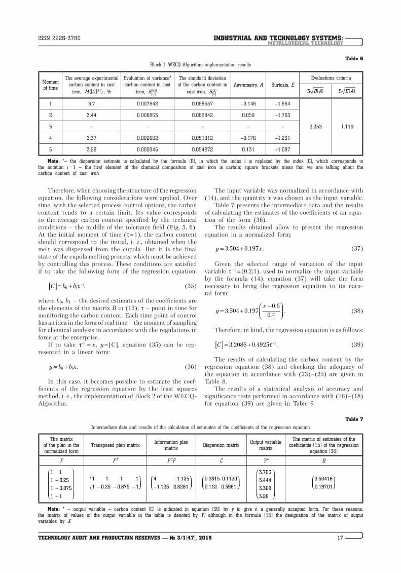
6.2. The results of the practical implementation of the WECQ-Algorithm. Primary industrial data was obtained on the basis of a technological audit of the cupola-mixer duplex process. Duration of observations – 78 days. The sampling times were numbered in order: 1, 2, 3, 4, 5, with an interval of 2 hours, starting from the first sample. The results are shown in Table 5.
Table 5
The results of a chemical analysis of the carbon content in a batch process
No. of industrial
experiment
The carbon content of cast iron, [C], %
Sampling moments
1 2 3 4 5
1 3.74 3.35 * 3.45 3.38
2 3.79 3.56 * 3.34 3.28
3 3.6 3.48 * 3.37 3.21
4 3.59 3.36 * 3.39 3.2
5 3.8 3.55 * 3.4 3.28
6 3.6 3.38 * 3.38 3.28
7 3.69 3.46 * 3.35 3.34
8 3.8 3.49 * 3.42 3.25
9 3.8 3.35 * 3.32 3.3
10 3.6 3.35 * 3.41 3.33
11 3.76 3.54 * 3.28 3.22
12 3.67 3.46 * 3.3 3.29
Note: * – the data for time point 3 were not taken into account for the practical implementation of the algorithm, since it was planned to be used for further testing the hypothesis about the algorithm’s operability
For each moment of time (k = 1, ..., 5), operations of Block 1 of the WECQ-Algorithm were performed (Fig. 7).
Table 6 shows the results of checking the form of the law of distribution of carbon content at each time moment k.
Table 6 shows that the conditions of normality of the distribution are fulfilled by the criterion of «asymmetry», but by the criterion of «excess» they are fulfilled only for the moment of time k = 5. This means that in the first periods of the process the carbon content is significantly unstable, as evidenced by the value of E, the meaning of which in a known manner indicates the shape of the distribution curve. However, despite this fact, it is possible to recognize the law of distribution of carbon content as normal. An argument in favor of this may be the assump-tion that on a larger sample of data the kurtosis condi-tion could be fulfilled. Therefore, it is possible to go to Block 2 of the WECQ-Algorithm, choosing as the output variable the carbon content at time instants k = 1, ..., 5, and as an input variable, some kind of function of time. The choice of the input variable is associated with the justification of the structure of the regression equation, which is the kinetic equation of the change in carbon content over time. Therefore, the choice of the struc-ture of the regression equation should take into account the physicochemical meaning of the processes leading to a change in the carbon content (Fig. 5, 6). The lack of a general representation of the kinetic equation in the traditional form – the differential equation describing the speed of the process – and the difficulty of construct-ing it directly force one to resort only to a qualitative assessment when choosing the structure of the equation. It should be noted that an error in the choice of the structure of the equation can lead to an inadequate result from the point of view of a physicochemical description of the process, although from a statistical point of view the equation can be adequate.
Fig. 8. Algorithm for evaluating the «whole» control quality (Block 3, 4)
BLOCK 3Analysis of variance:
( )( )( )2
121 ,
1
Kk
k
n M x xs
K=
−=
−
∑
( )( )1
1
,K
k
k
x K M x−
=
= ∑
( ) ( )( )( )2
2
1 1 122 ,
K n Kk
kjk j k
x x n M x x
snK K
= = =
− − −=
−
∑∑ ∑
21
22
,cr
sF F
s= ≥
( )( ) ( )( ) ( )( ) ( )( )( )1 1 1 1 , 1,..,4r rcrM x M x t s M x M x r+ +− > − =
Commentto the block
Checking the significance of the effect of the selected control option on the stabilization of the composition of the chemical element in relation to which control is carried out:
If
( )( ) ( )( )1k kcrM x M x t s+ − ≥ ,
then the influence of control is significant and there is a transition of the process from non-stationary to stationary mode
BLOCK 4Calculation of the probability of a chemical element falling out of the tolerance field:
( )( )( )
( )( )( )
max imin1
k ki i i
k ki i
x M x x M xФ Ф
s s
− − ∆ = − −
Commentto the block
Assessment of the «whole» control quality performed within the framework of the duplex process management system adopted at the enterprise
INDUSTRIAL AND TECHNOLOGY SYSTEMS:METALLURGICAL TECHNOLOGY
17TECHNOLOGY AUDIT AND PRODUCTION RESERVES — № 3/1(47), 2019
ISSN 2226-3780
Therefore, when choosing the structure of the regression equation, the following considerations were applied. Over time, with the selected process control options, the carbon content tends to a certain limit. Its value corresponds to the average carbon content specified by the technical conditions – the middle of the tolerance field (Fig. 5, 6). At the initial moment of time (τ = 1), the carbon content should correspond to the initial, i. e., obtained when the melt was dispensed from the cupola. But it is the final state of the cupola melting process, which must be achieved by controlling this process. These conditions are satisfied if to take the following form of the regression equation:
C b b[ ] = + −0 1
1τ , (35)
where b0, b1 – the desired estimates of the coefficients are the elements of the matrix B in (15); τ – point in time for monitoring the carbon content. Each time point of control has an idea in the form of real time – the moment of sampling for chemical analysis in accordance with the regulations in force at the enterprise.
If to take τ− =1 x, y = [C], equation (35) can be rep-resented in a linear form:
y b b x= +0 1 . (36)
In this case, it becomes possible to estimate the coef-ficients of the regression equation by the least squares method, i. e., the implementation of Block 2 of the WECQ-Algorithm.
The input variable was normalized in accordance with (14), and the quantity x was chosen as the input variable.
Table 7 presents the intermediate data and the results of calculating the estimates of the coefficients of an equa-tion of the form (36).
The results obtained allow to present the regression equation in a normalized form:
y x= +3 504 0 197. . . (37)
Given the selected range of variation of the input variable τ–1 = (0.2;1), used to normalize the input variable by the formula (14), equation (37) will take the form necessary to bring the regression equation to its natu- ral form:
yx
= +−
3 504 0 1970 6
0 4. .
.
.. (38)
Therefore, in kind, the regression equation is as follows:
C[ ] = + −3 2086 0 4925 1. . .τ (39)
The results of calculating the carbon content by the regression equation (38) and checking the adequacy of the equation in accordance with (23)–(25) are given in Table 8.
The results of a statistical analysis of accuracy and significance tests performed in accordance with (16)–(18) for equation (39) are given in Table 9.
Table 6Block 1 WECQ-Algorithm implementation results
Moment of time
The average experimental carbon content in cast
iron, M C k([ ] )( ) , %
Evaluation of variance* carbon content in cast
iron, S Ck
[ ]( )2
The standard deviation of the carbon content in
cast iron, S Ck
[ ]( )
Asymmetry, A Kurtosis, EEvaluations criteria
3 D A( ) 5 E A( )
1 3.7 0.007842 0.088557 –0.146 –1.864
2.253 1.119
2 3.44 0.006863 0.082842 0.059 –1.763
3 – – – – –
4 3.37 0.002602 0.051012 –0.176 –1.231
5 3.28 0.002945 0.054272 0.131 –1.097
Note: *– the dispersion estimate is calculated by the formula (8), in which the index i is replaced by the index [C], which corresponds to the notation i = 1 – the first element of the chemical composition of cast iron is carbon; square brackets mean that we are talking about the carbon content of cast iron
Table 7
Intermediate data and results of the calculation of estimates of the coefficients of the regression equation
The matrix of the plan in the normalized form
Transposed plan matrixInformation plan
matrixDispersion matrix
Output variable matrix
The matrix of estimates of the coefficients (15) of the regression
equation (36)
F FT F TF C Y* B
1 1
1 0 25
1 0 875
1 1
−−−
.
.
1 1 1 1
1 0 25 0 875 1− − −
. .
4 1 125
1 125 2 8281
−−
.
. .
0 2815 0 1120
0 112 0 3981
. .
. .
3 703
3 444
3 368
3 28
.
.
.
.
3 50416
0 19701
.
.
Note: * – output variable – carbon content [C] is indicated in equation (36) by y to give it a generally accepted form. For these reasons, the matrix of values of the output variable in the table is denoted by Y, although in the formula (15) the designation of the matrix of output variables by X
INDUSTRIAL AND TECHNOLOGY SYSTEMS:METALLURGICAL TECHNOLOGY
18 TECHNOLOGY AUDIT AND PRODUCTION RESERVES — № 3/1(47), 2019
ISSN 2226-3780
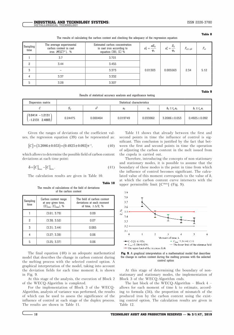
Given the ranges of deviations of the coefficient val-ues, the regression equation (39) can be represented as:
C[ ] = ±( ) + ±( ) −3 2086 0 053 0 4925 0 092 1. . . . ,τ (40)
which allows to determine the possible field of carbon content deviations at each time point:
δ = [ ] −[ ]C Cmax min
. (41)
The calculation results are given in Table 10.
Table 10
The results of calculations of the field of deviations of the carbon content
Sampling time
Carbon content range at any given time, ([C]min; [C]max), %
The field of carbon content deviations at each moment
of time, ± Δ/2, %
1 (3.61; 3.79) 0.09
2 (3.38; 3.52) 0.07
3 (3.31; 3.44) 0.065
4 (3.27; 3.39) 0.06
5 (3.25; 3.37) 0.06
The final equation (40) is an adequate mathematical model that describes the change in carbon content during the melting process with the selected control option. A graphical interpretation of the model, taking into account the deviation fields for each time moment k, is shown in Fig. 9.
At this stage of the analysis, the execution of Block 2 of the WECQ-Algorithm is completed.
For the implementation of Block 3 of the WECQ-Algorithm, analysis of variance was performed, the results of which can be used to assess the significance of the influence of control at each stage of the duplex process. The results are shown in Table 11.
Table 11 shows that already between the first and second points in time the influence of control is sig-nificant. This conclusion is justified by the fact that bet-ween the first and second points in time the operation of adjusting the carbon content in the melt issued from the cupola is carried out.
Therefore, introducing the concepts of non-stationary and stationary modes, it is possible to assume that the boundary of these modes is the point in time from which the influence of control becomes significant. The calcu-lated value of this moment corresponds to the value of k, at which the carbon content curve intersects with the upper permissible limit [Cmax] (Fig. 9).
Fig. 9. A graphical interpretation of a mathematical model that describes the change in carbon content during the melting process with the selected
control option
At this stage of determining the boundary of non-stationary and stationary modes, the implementation of Block 3 of the WECQ-Algorithm ends.
The last block of the WECQ-Algorithm – Block 4 – allows for each moment of time k to estimate, accord-ing to formula (34), the proportion of mismatch of the produced iron by the carbon content using the exist-ing control option. The calculation results are given in Table 12.
Table 8The results of calculating the carbon content and checking the adequacy of the regression equation
Sampling time
The average experimental carbon content in cast
iron M C k([ ] ),( ) %
Estimated carbon concentration in cast iron according to
equation (38), [C] %s
nSD
R2
1
=j
sS
e
E2
2
=j
Fj1, j2 Fcr
1 3.7 3.701
0.01303 0.005563 2.34 5.12
2 3.44 3.455
3 – 3.373
4 3.37 3.332
5 3.28 3.307
Table 9Results of statistical accuracy analysis and significance testing
Dispersion matrix Statistical characteristics
C SE s2 s0 s1 b t scr0 0± b t scr1 1±
0 8414 1 2131
1 2131 2 4883
. .
. .
−−
0.24475 0.000464 0.019749 0.033962 3.2086 ± 0.053 0.4925 ± 0.092

INDUSTRIAL AND TECHNOLOGY SYSTEMS:METALLURGICAL TECHNOLOGY
19TECHNOLOGY AUDIT AND PRODUCTION RESERVES — № 3/1(47), 2019
ISSN 2226-3780
Table 11Results of variance analysis
Statistical characteristics
Levels of influence of the control factor for time moments k
1 2 3 4 5
3.74 3.35 * 3.45 3.38
3.79 3.56 * 3.34 3.28
3.6 3.48 * 3.37 3.21
3.59 3.36 * 3.39 3.2
3.8 3.55 * 3.4 3.28
3.6 3.38 * 3.38 3.28
3.69 3.46 * 3.35 3.34
3.8 3.49 * 3.42 3.25
3.8 3.35 * 3.32 3.3
3.6 3.35 * 3.41 3.33
3.76 3.54 * 3.28 3.22
3.67 3.46 * 3.3 3.29
M C k([ ] )( ) 3.701 3.455 – 3.332 3.307
[ ]C 3.44875 3.44875 – 3.44875 3.44875
M C Ck([ ] ) [ ]( ) − 0.06363 3.91E-05 – 0.0136 0.0201
s12 0.389571
s22 0.00575
j1 3
j2 44
F 67.75
Fcr 2.82
s M x M xr( ( ) ( ))( ) ( )1 1+ − 0.030958
Tcr 2.07
TcrS 0.064082
M x M xr( ) ( )( ) ( )1 1+ − 0 0.246 0.328 0.369 0.394
Note: * – the data for time point 3 were not taken into account for the practical implementation of the algorithm, since it was planned to be used for further testing the hypothesis about the algorithm’s operability
Table 12
Evaluation results of the «whole» control of the «cupola – mixer» duplex process
The proportion of mismatch of smelted iron in carbon content when using the existing control option for time moments k
1 2 3* 4 5
Δ1 Δ2 Δ3 Δ4 Δ5
0.988 0.235 0.198 0.005 0.071
Note: * – calculation is performed according to the Table 8
Presented in the Table 12 results are the result of the implementation of the algorithm for assessing the «whole» quality of control performed within the framework of the duplex process management system adopted at the en-terprise. It allows to determine which of the sections of the technological process requires optimization of control, understood in the sense of ensuring a given final state with a minimum duration of unsteady mode.
It can be seen from the above example that, in the considered case, improvement of control of the cupola melting process is required, since the specified final state is not provided by the existing control option.
6.3. Possible options for improving the control process based on the implementation of the proposed WECQ-Algorithm. Improving the control process is possible in two ways:
1) improvement of the control process in the manual melting mode;
2) improvement of the control system at the automa-tion level.
In both cases, the temperature and carbon content of cast iron are subject to regulation. The results of the technological audit of the smelting show that the parameter determining the need for temperature control is the diffe-rence in the level of the idle charge. If it is insufficient (42), then the temperature of cast iron decreases, although the speed of movement of the melt front increases.
Δh h hah sh= − <1 1 0, (42)
where h1ah – the actual level of idle charge from the axis of the lower row of tuyeres; h1sh – the set idle charge level from the axis of the lower row of tuyeres. In the general case, the height of the blank ears depends on the design parameters of the cupola and the accepted technological modes of melting:
h T d f n W Tw O Rpor1 1 2= j ( ) ,, , , , , ,Δ Σ (43)
where h1 – idle charge level, mm; j1 2( ) , , , , , ,Δ ΣT d f n W Tw O Rpor – temperature difference function of cast iron at the actual design parameters of the cupola and the actual technological melting conditions:
– a group of structural parameters of the cupola:d – diameter of the cupola in the light, mm;Σf – total sectional area of the tuyeres, mm2;n – number of rows of tuyeres;– group of technological melting modes:W – amount of air supplied to the cupola, m3/m2;Tw – temperature of the air supplied to the cupola, °С;O2 – oxygen concentration in the air supplied to the cupola, %;Rpor – the porosity of a idle charge.Therefore, the temperature control condition can be
represented as follows:
Δh T Tsh< → <0 , (44)
where Δh – height difference of the idle charge, mm; T – actual (recorded) temperature of cast iron, °C; Tsh – set temperature of cast iron.
V hcoke = j2 1( ), (45)
where Vcoke – coke volume idle charge, m3; j2(h1) – function of the height of the blank spike.
Therefore, regulation should be carried out by sup-plying an additional working fuel spike. Fig. 10–12 show a demonstration of the principle of temperature control.
In Fig. 10, h3 denotes the height of the working fuel charge introduced into the cupola to adjust the tempera-ture, determined from the Vcoke value with the existing cupola diameter in the light.

INDUSTRIAL AND TECHNOLOGY SYSTEMS:METALLURGICAL TECHNOLOGY
20 TECHNOLOGY AUDIT AND PRODUCTION RESERVES — № 3/1(47), 2019
ISSN 2226-3780
If the level of idle charge is higher than necessary, then the parameter determining the need for regulation is the cupola productivity:
Δh h hah sh= − >1 1 0, (46)
and the controlling condition can be represented as follows:
Δh T Tah> → >0 , (47)
Δh Q Qsh> → <0 , (48)
where Qsh – set value of the cupola productivity, t/h.
h Q d f n Q Tw O Rpor2 3 2= j ( ) ,, , , , , ,Δ Σ (49)
Fig. 10. Temperature control conditions: 1 – idle charge; 2 – metal charge; 3 – working fuel charge
Fig. 11. The block diagram of the temperature controller
Fig. 12. The principle of temperature regulation

INDUSTRIAL AND TECHNOLOGY SYSTEMS:METALLURGICAL TECHNOLOGY
21TECHNOLOGY AUDIT AND PRODUCTION RESERVES — № 3/1(47), 2019
ISSN 2226-3780
where h2 – height of the metal spike, mm; j3 2( ) , , , , , ,Δ ΣQ d f n Q Tw O Rpor – function of the difference in productivity of the cupola with the actual structural parameters of the cupola and the actual technological modes of melting.
V hmet = j4 2( ), (50)
where Vmet – volume of the furnace charge in a metal charge, m3; j4(h2) – function of the height of the metal charge.
Therefore, performance control should be performed by supplying an additional metal charge. Fig. 13–15 show a demonstration of the control principle.
For the practical implementation of the proposed regula-tion principle, it is necessary to conduct additional studies on mathematical modeling of the process and obtain an adequate description of the form (43), (45), (49), (50). The results obtained in this case can be used either as part of a decision support system in the manual control process, or for the synthesis of a controller as part of an integrated automated cupola melting control system. A simplified functional diagram of the automation system of the cupola process is presented in Fig. 16.
Technical implementation options are presented in Fig. 17, 18.
Fig. 13. Conditions for productivity control: 1 – idle charge; 2 – metal charge; 3 – working fuel charge
Fig. 14. Block diagram of the cupola performance controller
Fig. 15. The principle of controlling the cupola productivity

INDUSTRIAL AND TECHNOLOGY SYSTEMS:METALLURGICAL TECHNOLOGY
22 TECHNOLOGY AUDIT AND PRODUCTION RESERVES — № 3/1(47), 2019
ISSN 2226-3780
Fig. 16. The simplified functional diagram of the automation system of the cupola process: 1 – cupola; 2 – spark arrestor; 3 – tuyere belt; 4 – wet cleaner; 5 – radiation recuperator; 6 – convective recuperator; 7 – smoke exhaust; 8 – fan; 9 – receiver
Fig. 17. The block diagram of the part of the loading control system, including regulation of the temperature and productivity of the cupola by supplying a working fuel and metal charge: 1 – hopper with coke; 2 – hopper with a metal charge; 3 – actuator of the loading system
of the metal charges; 4 – actuator loading system of the working fuel charge
In Fig. 17 the following notation is used: u11(a) – includ-
ing the signal of the drive of the gate of the hopper with coke coming from the automated control system; u21
(a) – the switching signal of the hopper gate drive with a metal charge coming from the automated control system (Fig. 18).
In Fig. 18 the following notation is accepted: K1, K2 – limit switches near and far, respectively; f1
(h), f2(h) – control
signals coming to the solenoids of the distributors from the manual control system; fi
(a), fi(a) – control signals coming
to the solenoids of the valves from the trigger from the
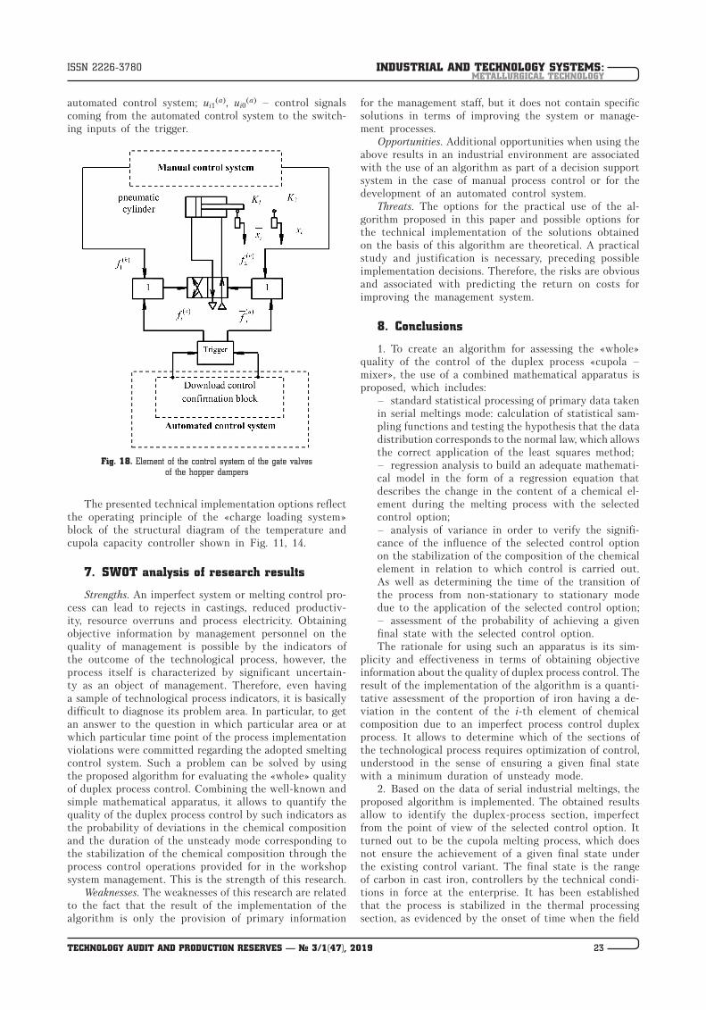
INDUSTRIAL AND TECHNOLOGY SYSTEMS:METALLURGICAL TECHNOLOGY
23TECHNOLOGY AUDIT AND PRODUCTION RESERVES — № 3/1(47), 2019
ISSN 2226-3780
automated control system; ui1(a), ui0
(a) – control signals coming from the automated control system to the switch-ing inputs of the trigger.
Fig. 18. Element of the control system of the gate valves
of the hopper dampers
The presented technical implementation options reflect the operating principle of the «charge loading system» block of the structural diagram of the temperature and cupola capacity controller shown in Fig. 11, 14.
7. SWOT analysis of research results
Strengths. An imperfect system or melting control pro-cess can lead to rejects in castings, reduced productiv-ity, resource overruns and process electricity. Obtaining objective information by management personnel on the quality of management is possible by the indicators of the outcome of the technological process, however, the process itself is characterized by significant uncertain-ty as an object of management. Therefore, even having a sample of technological process indicators, it is basically difficult to diagnose its problem area. In particular, to get an answer to the question in which particular area or at which particular time point of the process implementation violations were committed regarding the adopted smelting control system. Such a problem can be solved by using the proposed algorithm for evaluating the «whole» quality of duplex process control. Combining the well-known and simple mathematical apparatus, it allows to quantify the quality of the duplex process control by such indicators as the probability of deviations in the chemical composition and the duration of the unsteady mode corresponding to the stabilization of the chemical composition through the process control operations provided for in the workshop system management. This is the strength of this research.
Weaknesses. The weaknesses of this research are related to the fact that the result of the implementation of the algorithm is only the provision of primary information
for the management staff, but it does not contain specific solutions in terms of improving the system or manage-ment processes.
Opportunities. Additional opportunities when using the above results in an industrial environment are associated with the use of an algorithm as part of a decision support system in the case of manual process control or for the development of an automated control system.
Threats. The options for the practical use of the al-gorithm proposed in this paper and possible options for the technical implementation of the solutions obtained on the basis of this algorithm are theoretical. A practical study and justification is necessary, preceding possible implementation decisions. Therefore, the risks are obvious and associated with predicting the return on costs for improving the management system.
8. Conclusions
1. To create an algorithm for assessing the «whole» quality of the control of the duplex process «cupola – mixer», the use of a combined mathematical apparatus is proposed, which includes:
– standard statistical processing of primary data taken in serial meltings mode: calculation of statistical sam-pling functions and testing the hypothesis that the data distribution corresponds to the normal law, which allows the correct application of the least squares method;– regression analysis to build an adequate mathemati-cal model in the form of a regression equation that describes the change in the content of a chemical el-ement during the melting process with the selected control option;– analysis of variance in order to verify the signifi-cance of the influence of the selected control option on the stabilization of the composition of the chemical element in relation to which control is carried out. As well as determining the time of the transition of the process from non-stationary to stationary mode due to the application of the selected control option;– assessment of the probability of achieving a given final state with the selected control option.The rationale for using such an apparatus is its sim-
plicity and effectiveness in terms of obtaining objective information about the quality of duplex process control. The result of the implementation of the algorithm is a quanti-tative assessment of the proportion of iron having a de- viation in the content of the i-th element of chemical composition due to an imperfect process control duplex process. It allows to determine which of the sections of the technological process requires optimization of control, understood in the sense of ensuring a given final state with a minimum duration of unsteady mode.
2. Based on the data of serial industrial meltings, the proposed algorithm is implemented. The obtained results allow to identify the duplex-process section, imperfect from the point of view of the selected control option. It turned out to be the cupola melting process, which does not ensure the achievement of a given final state under the existing control variant. The final state is the range of carbon in cast iron, controllers by the technical condi-tions in force at the enterprise. It has been established that the process is stabilized in the thermal processing section, as evidenced by the onset of time when the field

INDUSTRIAL AND TECHNOLOGY SYSTEMS:METALLURGICAL TECHNOLOGY
24 TECHNOLOGY AUDIT AND PRODUCTION RESERVES — № 3/1(47), 2019
ISSN 2226-3780
of deviations of the carbon content falls inside the tole-rance field provided for by the technical conditions. This occurs between the first and second moments of sampling, which determines the instant of transition of the process from non-stationary to stationary mode.
3. The formalization of the problem of optimal regu-lation of the temperature regime of cupola melting and cupola furnace productivity, as well as conceptual options for the technical implementation of the regulation system is proposed. In particular, a simple controller circuit is proposed, which provides the possibility of maintaining a constant temperature of cast iron and cupola productivity by regulating the level of idle and metal charges. In this case, the process is controlled by supplying control signals to the actuators of the hopper gates with coke and a metal charge formed by manual or automated control systems. It should be noted that for the practical implementation of such a solution, it is necessary to have adequate mathe-matical models that describe the sequentially connected parts of the regulation system. The obtained results in this case can be used either as part of a decision support system in the manual control process, or for the synthesis of a controller as part of an integrated automated cupola melting control system.
References
1. Luis, C., lvarez, L., Ugalde, M., Puertas, I. (2002). A technical note cupola efficiency improvement by increasing air blast tem-perature. Journal of Materials Processing Technology, 120 (1-3), 281–289. doi: http://doi.org/10.1016/s0924-0136(01)01053-6
2. O’Brien, W. A., Ohio, F. (1948). Pat. No. 2 443 960 USA. Control means for cupola furnaces. United States Patent Of-fice. Serial No. 525,686 5 Claims (CI. 266–30)
3. Matiukhin, V. I., Iaroshenko, Iu. G., Matiukhina, A. V., Dud-ko, V. A., Punenkov, S. E. (2018). Povyshenie energoeffektivnosti tekhnologicheskikh protsessov vyplavki chuguna v shakhtnykh pechakh vagranochnogo tipa. Sovremennye nauchnye dostizheniia metallurgicheskoi teplotekhniki i ikh realizatsiia v promyshlen-nosti. Ekaterinburg: UrFU, 131–139.
4. Selianin, I. F., Feoktistov, A. V., Modzelevskaia, O. G., Beda-rev, S. A. (2014). Razrabotka resursosberegaiushhikh tekhnologii vagranochnogo protsessa na spetsializirovannom issledovatels-kom komplekse. Metallurgiia: tekhnologii, upravlenie, innovat-sii, kachestvo. Novokuznetsk, 150–155. Available at: https:// elibrary.ru/item.asp?id = 22406637
5. Kononchuk, S. V., Sabirzianov, T. G. (2013). Uluchshenie raboty koksovoi vagranki na osnove issledovaniia vzaimosviazi mezhdu parametrami vagranochnogo protsessa. Metallurgiia mashinostroe-niia, 1, 8–13.
6. Isnugroho, K., Birawidha, D. C. (2018). The production of pig iron from crushing plant waste using hot blast cupola.
Alexandria Engineering Journal, 57 (1), 427–433. doi: http://doi.org/10.1016/j.aej.2016.11.004
7. Larsen, E. D., Clark, D. E., Moore, K. L., King, P. E. (1997). Intelligent control of Cupola Melting. Available at: https://pdfs.semanticscholar.org/56c2/96af1d56d5cd963a5bcc38635142 e5fa1968.pdf
8. Moore, K. L., Abdelrahman, M. A., Larsen, E., Clark, D., King, P. (1998). Experimental control of a cupola furnace. Proceedings of the 1998 American Control Conference. ACC (IEEE Cat. No. 98CH36207). doi: http://doi.org/10.1109/acc.1998.703360
9. Jezierski, J., Janerka, K. (2011). Selected Aspects of Metal-lurgical and Foundry Furnace Dust Utilization. Polish Journal of Environmental Studies, 20 (1), 101–105.
10. Trufanov, I. D., Chumakov, K. I., Bondarenko, A. A. (2005). Ob-shheteoreticheskie aspekty razrabotki stokhasticheskoi sistemy avtomatizirovannoi ekspertnoi otsenki dinamicheskogo kachestva proizvodstvennykh situatsii elektrostaleplavleniia. Eastern-Euro-pean Journal of Enterprise Technologies, 6 (2 (18)), 52–58.
11. Trufanov, I. D., Metelskii, V. P., Chumakov, K. I., Lozinskii, O. Iu., Paranchuk, Ia. S. (2008). Energosberegaiushhee upravlenie elektrotekhnologicheskim kompleksom kak baza povysheniia energoeffektivnosti metallurgii stali. Eastern-European Journal of Enterprise Technologies, 6 (1 (36)), 22–29.
12. Lutsenko, I., Fomovskaya, E. (2015). Identification of target sys-tem operations. The practice of determining the optimal control. Eastern-European Journal of Enterprise Technologies, 6 (2 (78)), 30–36. doi: http://doi.org/10.15587/1729-4061.2015.54432
13. Lutsenko, I., Vihrova, E., Fomovskaya, E., Serdiuk, O. (2016). Development of the method for testing of efficiency criterion of models of simple target operations. Eastern-European Journal of Enterprise Technologies, 2 (4 (80)), 42–50. doi: http://doi.org/ 10.15587/1729-4061.2016.66307
14. Demin, D. A. (2013). Prymenenye yskusstvennoi ortohonaly-zatsyy v poyske optymalnoho upravlenyia tekhnolohycheskymy protsessamy v uslovyiakh neopredelennosty. Eastern-European Journal of Enterprise Technologies, 5 (9 (65)), 45–53. Available at: http://journals.uran.ua/eejet/article/view/18452
15. Demin, D. (2017). Synthesis of optimal control of technologi-cal processes based on a multialternative parametric descrip-tion of the final state. Eastern-European Journal of Enterprise Technologies, 3 (4 (87)), 51–63. doi: http://doi.org/10.15587/ 1729-4061.2017.105294
16. Demin, D. A. (2012). Synthesis of optimal temperature regulator of electroarc holding furnace bath. Naukovyi Visnyk Natsion-alnoho Hirnychoho Universytetu, 6, 52–58.
17. Demin, D. A. (2011). Methodology of forming functional in the optimal control electric smelting. Technology Audit and Production Reserves, 1 (1 (1)), 15–24. doi: http://doi.org/ 10.15587/2312-8372.2011.4082
18. Charykov, A. K. (1984). Matematicheskaia obrabotka rezultatov khimicheskogo analiza. Lenigrad: Khimiia, 168.
Demin Dmitriy, Doctor of Technical Sciences, Professor, Department of Foundry Production, National Technical University «Kharkіv Poly-technic Institute», Ukraine, e-mail: [email protected], ORCID: http://orcid.org/0000-0002-7946-3651