Embed Size (px)
Citation preview
1
FR134 ~ 7 Mar. 2013
Paris, France
Development of Under-Sodium Inspection Technique
Using Ultrasonic Waveguide Sensor
Young-Sang Joo, J.-H. Bae, C-G. Park and J.-B. Kim
2
Outline
� Under-Sodium Viewing (USV) Sensors
� Development of Plate-type Ultrasonic Waveguide Sensor
� Feasibility Tests in Water
� Under-Sodium Plate Waveguide Sensor
� Performance Tests in Sodium
� Summary
3
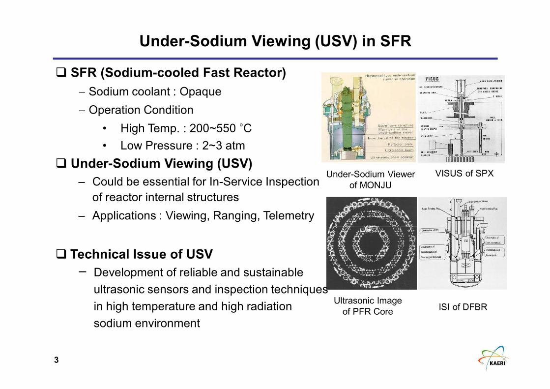
Under-Sodium Viewing (USV) in SFR
Ultrasonic Image
of PFR Core
Under-Sodium Viewer
of MONJU
VISUS of SPX
ISI of DFBR
� SFR (Sodium-cooled Fast Reactor)
− Sodium coolant : Opaque
− Operation Condition
• High Temp. : 200~550 °C
• Low Pressure : 2~3 atm
� Under-Sodium Viewing (USV)
– Could be essential for In-Service Inspection
of reactor internal structures
– Applications : Viewing, Ranging, Telemetry
� Technical Issue of USV
─ Development of reliable and sustainable
ultrasonic sensors and inspection techniques
in high temperature and high radiation
sodium environment
4
Under-Sodium Viewing (USV) Sensors in SFR
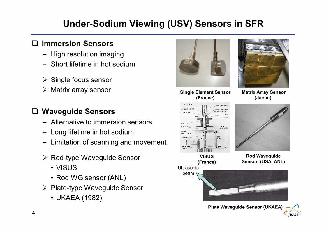
� Immersion Sensors
– High resolution imaging
– Short lifetime in hot sodium
� Single focus sensor
� Matrix array sensor
� Waveguide Sensors
– Alternative to immersion sensors
– Long lifetime in hot sodium
– Limitation of scanning and movement
� Rod-type Waveguide Sensor
• VISUS
• Rod WG sensor (ANL)
� Plate-type Waveguide Sensor
• UKAEA (1982)
Matrix Array Sensor
(Japan)
Single Element Sensor
(France)
VISUS
(France)
Rod Waveguide
Sensor (USA, ANL)
Plate Waveguide Sensor (UKAEA)
Ultrasonic
beam
5
A Novel Plate-type Ultrasonic Waveguide Sensor
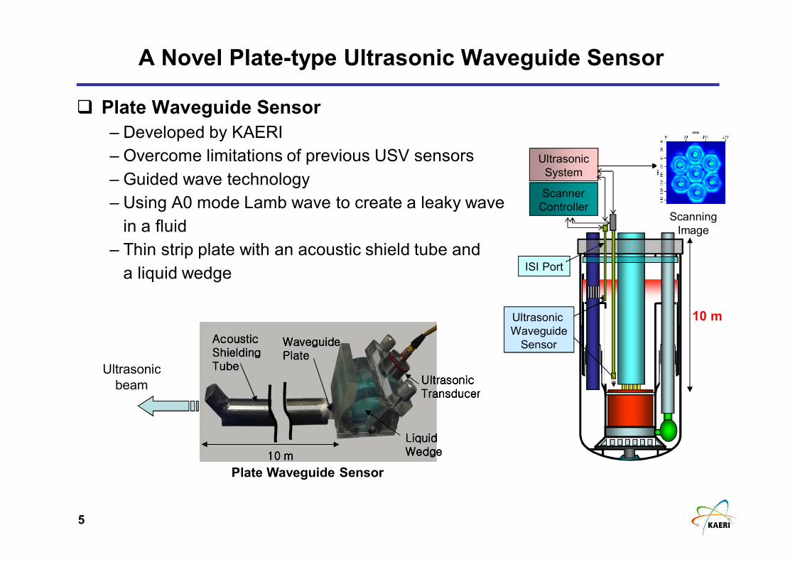
� Plate Waveguide Sensor
– Developed by KAERI
– Overcome limitations of previous USV sensors
– Guided wave technology
– Using A0 mode Lamb wave to create a leaky wave
in a fluid
– Thin strip plate with an acoustic shield tube and
a liquid wedge
Plate Waveguide Sensor
Liquid Liquid Liquid Liquid WedgeWedgeWedgeWedge
UltrasonicUltrasonicUltrasonicUltrasonicTransducerTransducerTransducerTransducer
AcousticAcousticAcousticAcousticShieldingShieldingShieldingShieldingTubeTubeTubeTube
10 10 10 10 mmmm
WaveguideWaveguideWaveguideWaveguidePlatePlatePlatePlate
Ultrasonic
beam
Ultrasonic
System
Scanning
Image
Scanner
Controller
ISI Port
Ultrasonic
Waveguide
Sensor
10 m
6
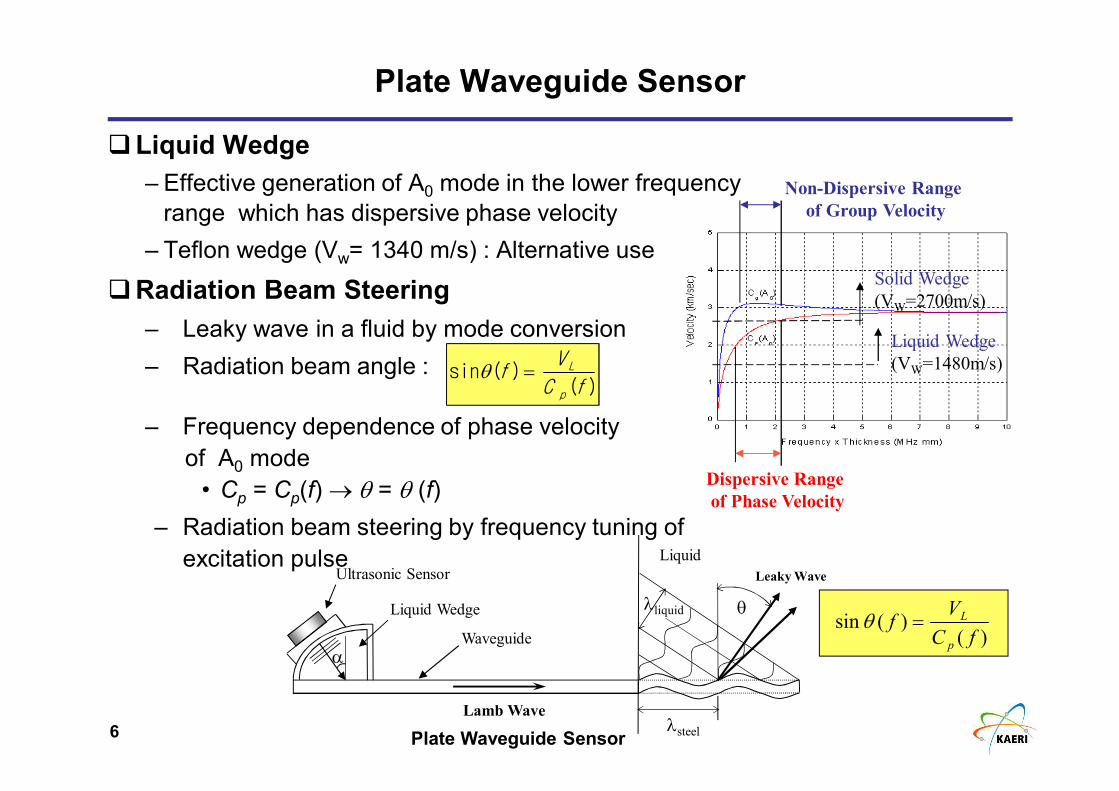
Solid Wedge
(VW=2700m/s)
Liquid Wedge
(VW=1480m/s)
Dispersive Range
of Phase Velocity
Non-Dispersive Range
of Group Velocity
Plate Waveguide Sensor
�Liquid Wedge
– Effective generation of A0 mode in the lower frequency
range which has dispersive phase velocity
– Teflon wedge (Vw= 1340 m/s) : Alternative use
�Radiation Beam Steering
– Leaky wave in a fluid by mode conversion
– Radiation beam angle :
– Frequency dependence of phase velocity
of A0 mode
• Cp = Cp(f) → θ = θ (f)
– Radiation beam steering by frequency tuning of
excitation pulse
Plate Waveguide Sensor
)()(sin
fC
Vf
p
L=θ
Ultrasonic Sensor
Waveguide
Liquid Wedge θ
Leaky Wave
λsteel
λliquid
Lamb Wave
Liquid
α
)()(sin
fC
Vf
p
L=θ
7
Radiation Beam of Plate Waveguide Sensor
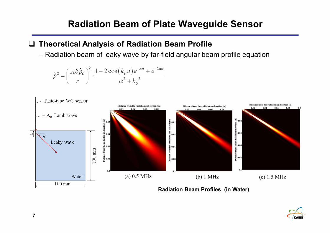
� Theoretical Analysis of Radiation Beam Profile
– Radiation beam of leaky wave by far-field angular beam profile equation
(b) 1 MHz (c) 1.5 MHz(a) 0.5 MHz
Radiation Beam Profiles (in Water)
8
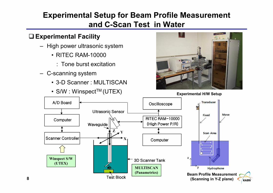
Experimental Setup for Beam Profile Measurement
and C-Scan Test in Water
�Experimental Facility
– High power ultrasonic system
• RITEC RAM-10000
: Tone burst excitation
– C-scanning system
• 3-D Scanner : MULTISCAN
• S/W : WinspectTM (UTEX)
MULTISCAN
(Panametrics)
UltrasonicUltrasonicUltrasonicUltrasonic SensorSensorSensorSensor
RITEC RAMRITEC RAMRITEC RAMRITEC RAM----10000100001000010000
(High Power P/R)(High Power P/R)(High Power P/R)(High Power P/R)
ComputerComputerComputerComputer
OscilloscopeOscilloscopeOscilloscopeOscilloscope
ComputerComputerComputerComputer
ScannerScannerScannerScanner ControllerControllerControllerController
A/DA/DA/DA/D BoardBoardBoardBoard
WaveguideWaveguideWaveguideWaveguide
TestTestTestTest BlockBlockBlockBlock
3333DDDD ScannerScannerScannerScanner TankTankTankTank
θθθθ
X
Y
Winspect S/W
(UTEX)
Z
Experimental H/W Setup
Beam Profile Measurement
(Scanning in Y-Z plane)
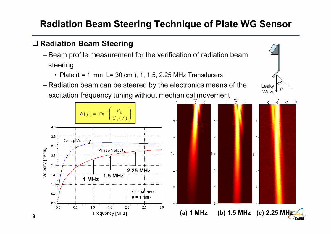
9
Radiation Beam Steering Technique of Plate WG Sensor
�Radiation Beam Steering
– Beam profile measurement for the verification of radiation beam
steering
• Plate (t = 1 mm, L= 30 cm ), 1, 1.5, 2.25 MHz Transducers
– Radiation beam can be steered by the electronics means of the
excitation frequency tuning without mechanical movement
= −
)()( 1
fC
VSinf
p
Lθ
1 MHz1.5 MHz
2.25 MHz
(a) 1 MHz (c) 2.25 MHz(b) 1.5 MHz
Leaky
Wave θ
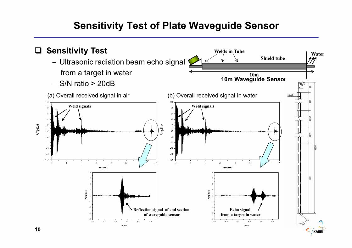
10
Sensitivity Test of Plate Waveguide Sensor
� Sensitivity Test
− Ultrasonic radiation beam echo signal
from a target in water
− S/N ratio > 20dB10m Waveguide Sensor
10m
Shield tubeWater
Welds in Tube
Reflection signal of end section
of waveguide sensor
Weld signals Weld signals
Echo signal
from a target in water
(b) Overall received signal in water(a) Overall received signal in air
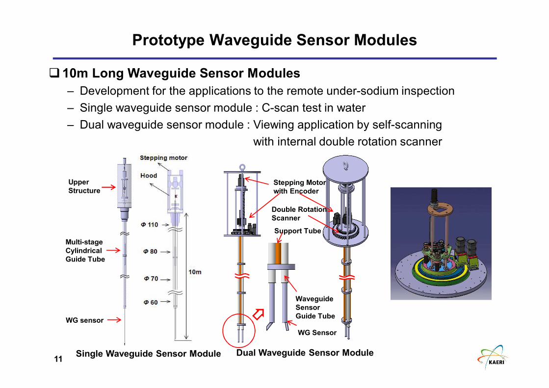
11
Support Tube
Waveguide
Sensor
Guide Tube
Stepping Motor
with Encoder
WG Sensor
Double Rotation
Scanner
Prototype Waveguide Sensor Modules
�10m Long Waveguide Sensor Modules
– Development for the applications to the remote under-sodium inspection
– Single waveguide sensor module : C-scan test in water
– Dual waveguide sensor module : Viewing application by self-scanning
with internal double rotation scanner
Single Waveguide Sensor Module Dual Waveguide Sensor Module
Multi-stage
Cylindrical
Guide Tube
WG sensor
Upper
Structure
12
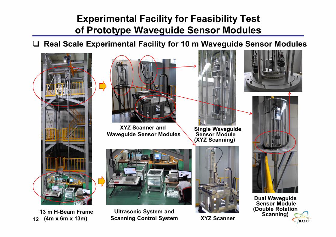
Experimental Facility for Feasibility Test
of Prototype Waveguide Sensor Modules
� Real Scale Experimental Facility for 10 m Waveguide Sensor Modules
13 m H-Beam Frame
(4m x 6m x 13m) XYZ Scanner
Single WaveguideSensor Module(XYZ Scanning)
Dual WaveguideSensor Module
(Double RotationScanning)
Ultrasonic System and
Scanning Control System
XYZ Scanner and
Waveguide Sensor Modules
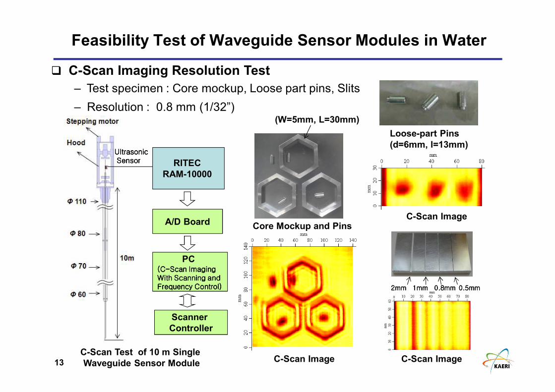
13
C-Scan Test of 10 m Single
Waveguide Sensor Module
UltrasonicUltrasonicUltrasonicUltrasonicSensorSensorSensorSensor
Scanner
Controller
A/D Board
PC(C(C(C(C----Scan ImagingScan ImagingScan ImagingScan ImagingWith Scanning and With Scanning and With Scanning and With Scanning and Frequency Control)Frequency Control)Frequency Control)Frequency Control)
RITEC
RAM-10000
� C-Scan Imaging Resolution Test
– Test specimen : Core mockup, Loose part pins, Slits
– Resolution : 0.8 mm (1/32”)
Feasibility Test of Waveguide Sensor Modules in Water
C-Scan Image
Core Mockup and Pins
C-Scan Image
2222mmmmmmmm 1111mmmmmmmm 0.80.80.80.8mmmmmmmm 0.50.50.50.5mmmmmmmm
Slit Specimen
Loose-part Pins
(d=6mm, l=13mm)
C-Scan Image
(W=5mm, L=30mm)
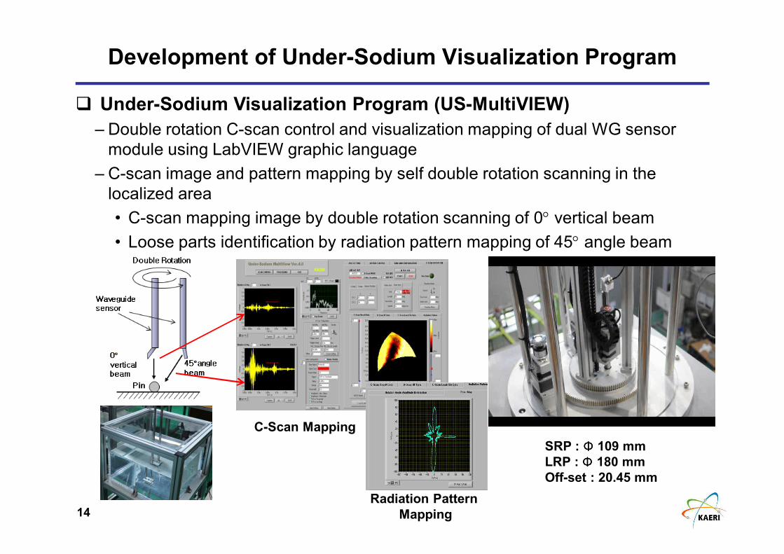
14
Development of Under-Sodium Visualization Program
� Under-Sodium Visualization Program (US-MultiVIEW)
– Double rotation C-scan control and visualization mapping of dual WG sensor
module using LabVIEW graphic language
– C-scan image and pattern mapping by self double rotation scanning in the
localized area
• C-scan mapping image by double rotation scanning of 0° vertical beam
• Loose parts identification by radiation pattern mapping of 45° angle beam
Radiation Pattern
Mapping
C-Scan Mapping
SRP : ΦΦΦΦ 109 mm
LRP : Φ Φ Φ Φ 180 mm
Off-set : 20.45 mm
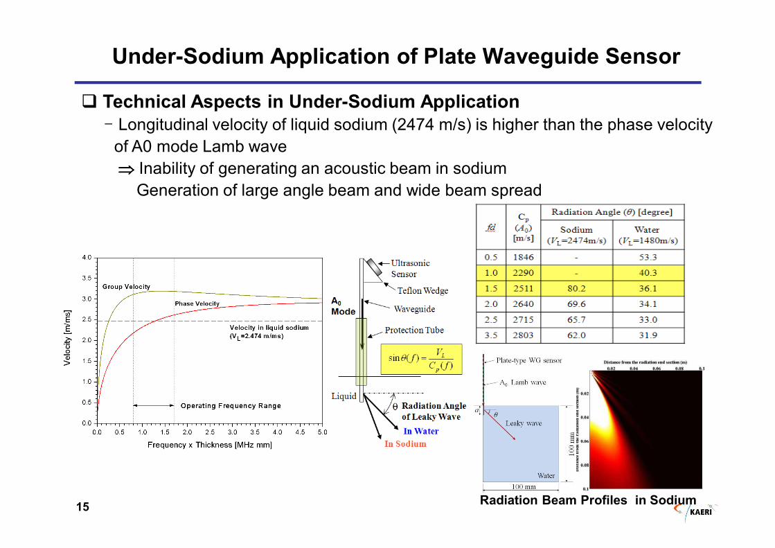
15
Under-Sodium Application of Plate Waveguide Sensor
� Technical Aspects in Under-Sodium Application
- Longitudinal velocity of liquid sodium (2474 m/s) is higher than the phase velocity
of A0 mode Lamb wave
⇒⇒⇒⇒ Inability of generating an acoustic beam in sodium
Generation of large angle beam and wide beam spread
Radiation Beam Profiles in Sodium
16
Plate Waveguide Sensor with a Beryllium Coating Layer
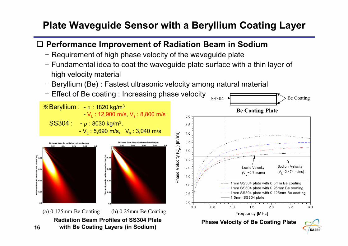
� Performance Improvement of Radiation Beam in Sodium
- Requirement of high phase velocity of the waveguide plate
- Fundamental idea to coat the waveguide plate surface with a thin layer of
high velocity material
- Beryllium (Be) : Fastest ultrasonic velocity among natural material
- Effect of Be coating : Increasing phase velocitySS304 Be Coating
Be Coating Plate※Beryllium : - ρ : 1820 kg/m3
- VL : 12,900 m/s, Vs : 8,800 m/s
SS304 : - ρ : 8030 kg/m3,
- VL : 5,690 m/s, Vs : 3,040 m/s
Phase Velocity of Be Coating Plate
(a) 0.125mm Be Coating (b) 0.25mm Be Coating
Radiation Beam Profiles of SS304 Plate
with Be Coating Layers (in Sodium)
17
Experimental Verification of Be Coating Effect
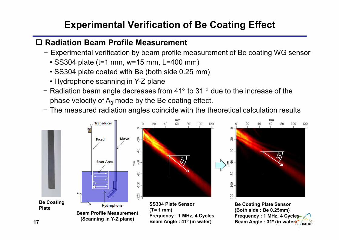
� Radiation Beam Profile Measurement
- Experimental verification by beam profile measurement of Be coating WG sensor
• SS304 plate (t=1 mm, w=15 mm, L=400 mm)
• SS304 plate coated with Be (both side 0.25 mm)
• Hydrophone scanning in Y-Z plane
- Radiation beam angle decreases from 41° to 31 ° due to the increase of the
phase velocity of A0 mode by the Be coating effect.
- The measured radiation angles coincide with the theoretical calculation results
SS304 Plate Sensor
(T= 1 mm)
Frequency : 1 MHz, 4 Cycles
Beam Angle : 41º (in water)
Be Coating Plate Sensor
(Both side : Be 0.25mm)
Frequency : 1 MHz, 4 Cycles
Beam Angle : 31º (in water)
Be Coating
PlateBeam Profile Measurement
(Scanning in Y-Z plane)
18
Be coating
(0.25 mm)Ni coating
(0.1 mm)
Under-Sodium
Waveguide Sensor Module
Under-Sodium Plate Waveguide Sensor
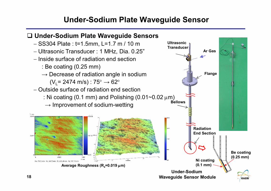
� Under-Sodium Plate Waveguide Sensors
− SS304 Plate : t=1.5mm, L=1.7 m / 10 m
− Ultrasonic Transducer : 1 MHz, Dia. 0.25”
− Inside surface of radiation end section
: Be coating (0.25 mm)
→ Decrease of radiation angle in sodium
(VL= 2474 m/s) : 75° → 62°− Outside surface of radiation end section
: Ni coating (0.1 mm) and Polishing (0.01~0.02 µm)
→ Improvement of sodium-wetting
Ar Gas
Bellows
Flange
Ultrasonic
Transducer
Radiation
End Section
Average Roughness (Ra=0.019 µµµµm)
19
Sodium Test Facility
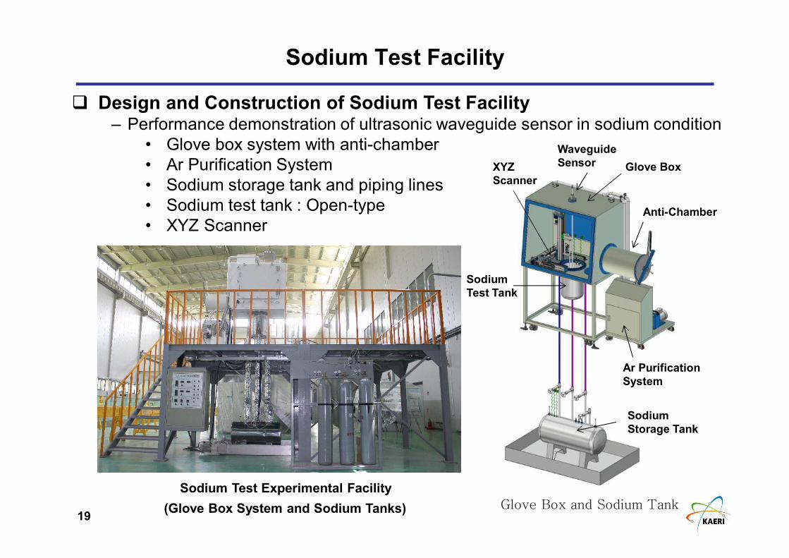
� Design and Construction of Sodium Test Facility– Performance demonstration of ultrasonic waveguide sensor in sodium condition
• Glove box system with anti-chamber
• Ar Purification System
• Sodium storage tank and piping lines
• Sodium test tank : Open-type
• XYZ Scanner
Glove Box and Sodium Tank
Glove Box
Ar Purification
System
Sodium
Storage Tank
Sodium
Test Tank
Waveguide
SensorXYZ
Scanner
Anti-Chamber
Sodium Test Experimental Facility
(Glove Box System and Sodium Tanks)
20
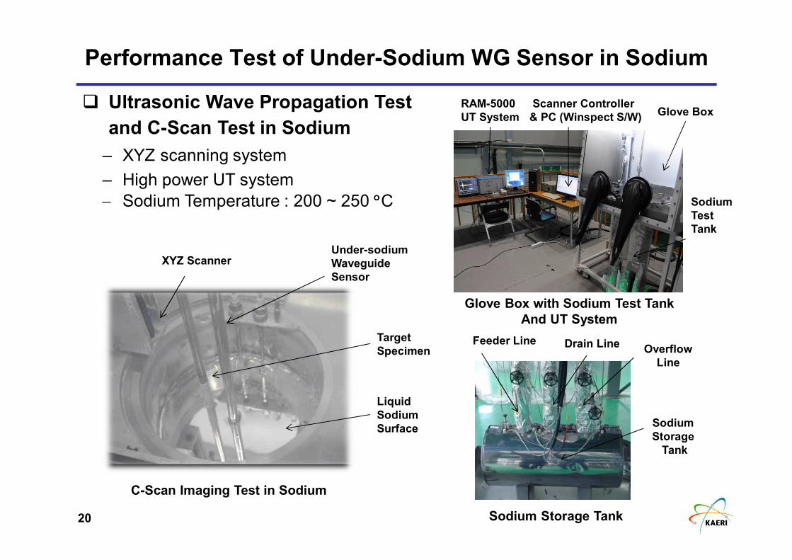
Performance Test of Under-Sodium WG Sensor in Sodium
� Ultrasonic Wave Propagation Test
and C-Scan Test in Sodium
– XYZ scanning system
– High power UT system
− Sodium Temperature : 200 ~ 250 °°°°C
Glove BoxScanner Controller
& PC (Winspect S/W)
RAM-5000
UT System
Liquid
Sodium
Surface
Under-sodium
Waveguide
Sensor
Target
Specimen
Sodium
Test
Tank
XYZ Scanner
Sodium Storage Tank
Sodium
Storage
Tank
Drain LineOverflow
Line
Feeder Line
Glove Box with Sodium Test Tank
And UT System
C-Scan Imaging Test in Sodium
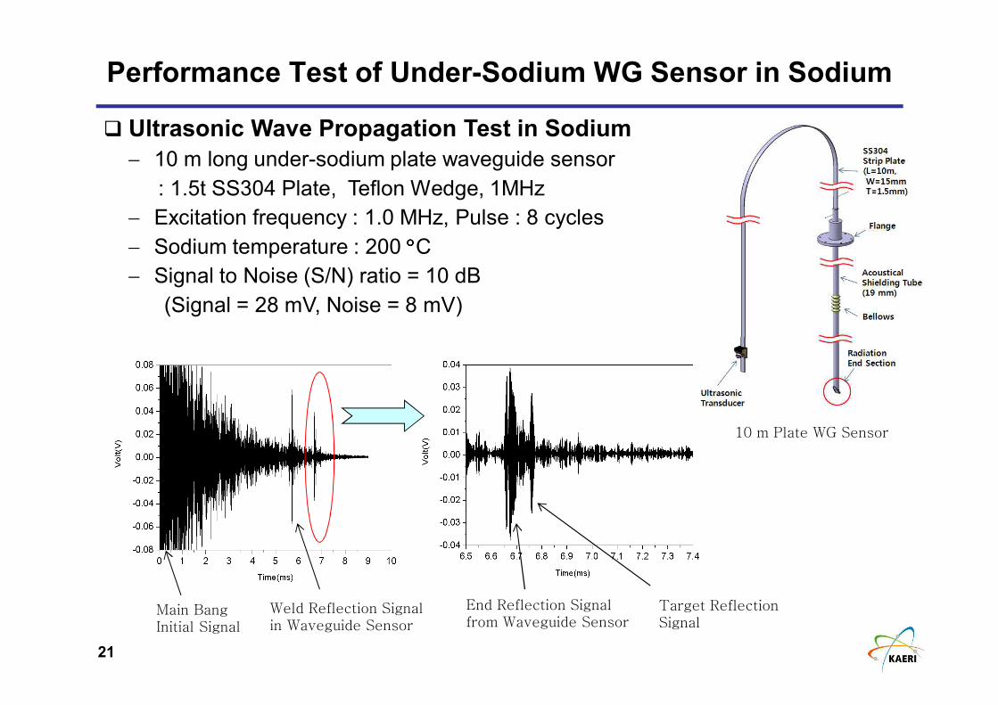
21
Target ReflectionSignal
Main BangInitial Signal
Weld Reflection Signalin Waveguide Sensor
End Reflection Signalfrom Waveguide Sensor
10 m Plate WG Sensor
� Ultrasonic Wave Propagation Test in Sodium
− 10 m long under-sodium plate waveguide sensor
: 1.5t SS304 Plate, Teflon Wedge, 1MHz
− Excitation frequency : 1.0 MHz, Pulse : 8 cycles
− Sodium temperature : 200 °°°°C− Signal to Noise (S/N) ratio = 10 dB
(Signal = 28 mV, Noise = 8 mV)
Performance Test of Under-Sodium WG Sensor in Sodium
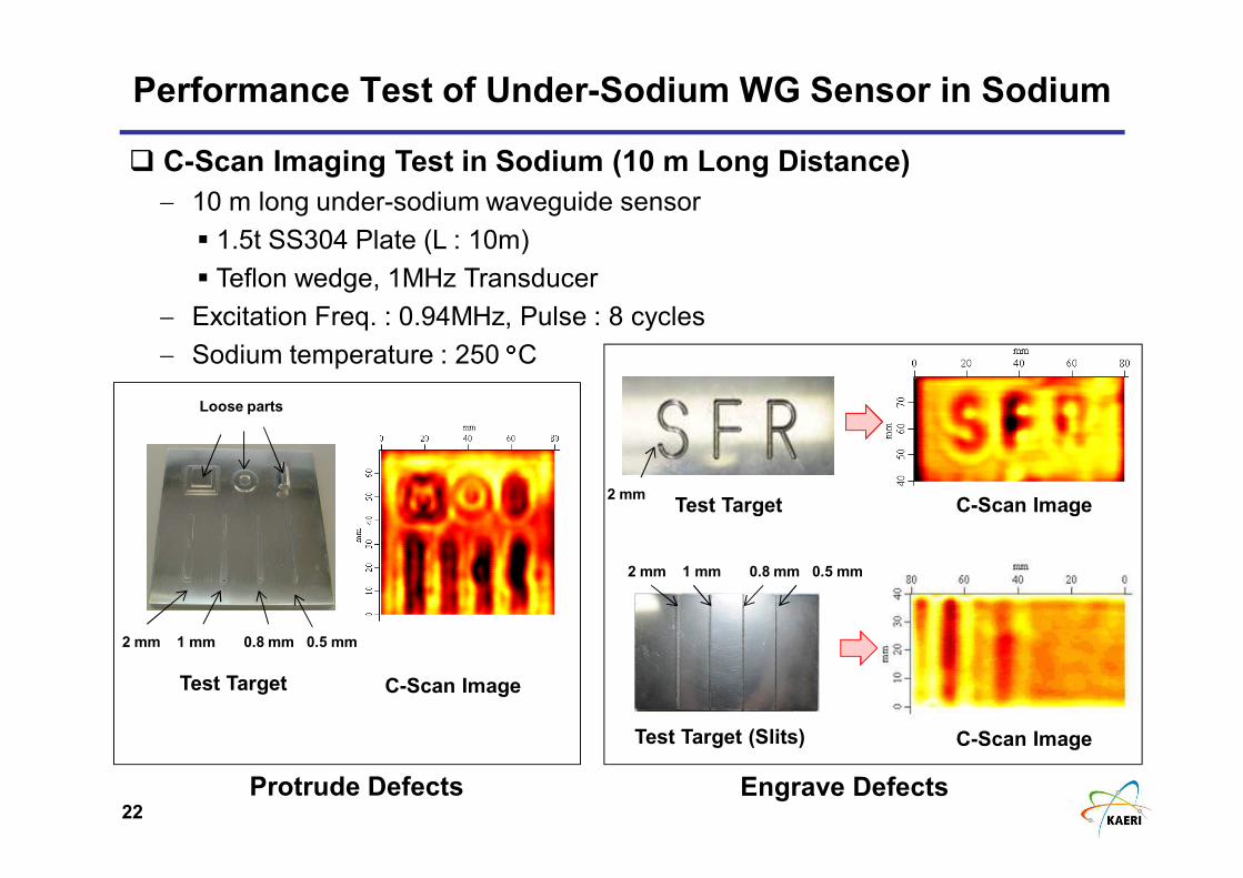
22
Test Target
2 mm 1 mm 0.8 mm 0.5 mm
Loose parts
Test Target
Test Target (Slits)
2 mm 1 mm 0.8 mm 0.5 mm
2 mm
� C-Scan Imaging Test in Sodium (10 m Long Distance)
− 10 m long under-sodium waveguide sensor
� 1.5t SS304 Plate (L : 10m)
� Teflon wedge, 1MHz Transducer
− Excitation Freq. : 0.94MHz, Pulse : 8 cycles
− Sodium temperature : 250 °°°°C
C-Scan Image
C-Scan Image
C-Scan Image
Protrude Defects Engrave Defects
Performance Test of Under-Sodium WG Sensor in Sodium
23
Summary
� A new idea and concept of plate-type ultrasonic waveguide sensor and
inspection technique have been suggested for under-sodium viewing
� Development of 10m long waveguide sensor modules and visualization
software program
� Feasibility verification of 10 m waveguide sensor modules in water
� Development of under-sodium ultrasonic waveguide sensor with Be and Ni
coating layers
� Setup of sodium test facility and performance demonstration of under-
sodium waveguide sensor in sodium
24
Thank You for Attention !