Embed Size (px)
Citation preview
Development of the Safety System for the Inner Tracking System of the ALICE Experiment
Pascal Herve Blanc1, Patricia Mendez Lorenzo1 , Xavier Pons1 on behalf of the ALICE *
ITS Collaboration.
CERN, Esplanade des Particules 1, 1211 Geneva 23, Switzerland.
Abstract. During the LHC Long Shutdown 2, the ALICE experiment has undergone numerous upgrades to cope with the large amount of data expected. Among all new elements integrated into ALICE, the experiment counts with a new Inner Tracking System (ITS), with innovative pixel sensors that will substantially improve the performance of the system. The new detector is powered up through a complex Low Voltage (LV) distribution, increasing the power dissipated by the detector and requiring the installation of a large number of temperature measurement points. In 2020, a new safety system has been developed to distribute the ITS LV interlock system and to monitor the new temperature values. The safety system is based on a Siemens S7-1500 PLC device. The control application governing the PLC has been configured through the UNICOS-CPC infrastructure made at CERN for the standardisation of industrial applications. UNICOS-CPC enables both the automatisation of control tasks governing the PLC and the interface to the WinCC OA based SCADA system. This paper provides a complete description of the setup of this safety system.
1 INTRODUCTION
During the LHC Long Shutdown (LS2), the ALICE [1] experiment has undertaken a major upgrade of its tracking detector [2]. The old system has been replaced by a new high-resolution detector consisting of 7 concentric layers.
The principal motivations behind this upgrade are the improvement of the impact parameter resolution and the tracking efÞciency, the increase of the resolution at low transverse momentum, the substantial increase of the data rate capability achieving readout rates as high as 50KHz in lead-lead collisions (the old detector was limited to 1 KHz) and the enabling of a fast removal and insertion of new modules during the yearly shutdowns [3].
In order to protect the detector against over temperatures, a large network of temperature measurements points has been setup, which are read out through a Siemens S7-1500 PLC (Programmable Logic Controller) [4] device.
The PLC programming has followed the CERN control system standards deÞned by UNICOS (UniÞed Industrial Control systems) [5]. The project has used the UNICOS-CPC (Continuous Project Control) [6] interface, in particular the UAB (UNICOS Application Builder v1.2.10) toolkit included in UNICOS-CPC. This tool enables the automatic creation
© The Authors, published by EDP Sciences. This is an open access article distributed under the terms of the Creative Commons Attribution License 4.0 (http://creativecommons.org/licenses/by/4.0/).
EPJ Web of Conferences 251, 04004 (2021) https://doi.org/10.1051/epjconf/202125104004CHEP 2021
of all elements necessary in both the control logic governing the PLC and the supervision layer handled by WinCC OA (Open Architecture v3.16) [7].
Both hardware setup of the safety system and its control software structures have been completed and validated.
2 THE ALICE ITS SAFETY SYSTEM (ITS2S) 2.1 The hardware architecture of the ITS2S
The ITS detector includes a large number of temperature measurement points. Up to 336 temperature sensors PT100 type are distributed in the overall detector according to the physical conÞguration of the ITS. These sensors are continuously monitored and surveyed by the ITS2S since they provide critical parameters for the correct operation of the detector. Any temperature value beyond the operation range predeÞned by the detector speciÞcations will trigger subsequent actions to guarantee the safety of the detector. The ITS2S receives and tracks also the main cooling plant status which supplies the chilled water to the detector. The distribution of the chilled water is made of 48 cooling loops. The operation of the ITS detector requires an extensive LV power distribution with a particular layout deÞned by the detector. The ITS2S is controlling permanently the LV power supplies by triggering the corresponding interlock actions according to the logic speciÞed by the detector. This logic depends on the temperature measured by the PT100 sensors and the correct operation of the detector cooling loops. The LV relies on 69 CAEN power supply modules A3009 requiring a single interlock signal per module. This conÞguration is complemented by 4 CAEN LV modules A2518 type including 2 interlock signals per module.
The LV CAEN interlock signals are hardwired to the ITS2S system. This physical electrical circuit is used for the interlock distribution and it is made applying a fail-safe logic method. The ITS2S is placed in a single 56U rack situated in the ALICE cavern UX-25, in a safe zone from radiation caused by the collisions. The PLC layout consists of 6 backplane extensions connected by ProÞnet network to the PLC CPU. The ProÞnet interface module is installed in the Þrst position of the backplane and the Input/Output (I/O) modules are installed successively in the backplanes. The Þrst 5 rails correspond to the readout of the temperatures and each backplane contains 10 Siemens Analogue Input (AI) modules connected to read out up to 8 PT100 temperature sensors in a 4 wire scheme avoiding any possible perturbation due to the cable length. The last backplane includes the Digital I/O (DI and DO) modules used for interfacing the cooling loop status signals and the CAEN power supply interlock production.
In terms of electronic signals, the ITS2S includes therefore the control of 336 AI coming from the temperatures, 48 DI collected from the cooling loops, 69 DO corresponding to the power supplies and 3 interlocks for the modules.
When the ALICE experiment is operating, the ITS2S rack is not accessible. For this reason the PLC CPU has been installed in the Counting Room (CR4) of ALICE, which is always accessible in case of maintenance needs. The remote connection between the CPU and the ITS2S rack is assured by the Siemens ProÞnet network.
2
EPJ Web of Conferences 251, 04004 (2021) https://doi.org/10.1051/epjconf/202125104004CHEP 2021
of all elements necessary in both the control logic governing the PLC and the supervision layer handled by WinCC OA (Open Architecture v3.16) [7].
Both hardware setup of the safety system and its control software structures have been completed and validated.
2 THE ALICE ITS SAFETY SYSTEM (ITS2S) 2.1 The hardware architecture of the ITS2S
The ITS detector includes a large number of temperature measurement points. Up to 336 temperature sensors PT100 type are distributed in the overall detector according to the physical conÞguration of the ITS. These sensors are continuously monitored and surveyed by the ITS2S since they provide critical parameters for the correct operation of the detector. Any temperature value beyond the operation range predeÞned by the detector speciÞcations will trigger subsequent actions to guarantee the safety of the detector. The ITS2S receives and tracks also the main cooling plant status which supplies the chilled water to the detector. The distribution of the chilled water is made of 48 cooling loops. The operation of the ITS detector requires an extensive LV power distribution with a particular layout deÞned by the detector. The ITS2S is controlling permanently the LV power supplies by triggering the corresponding interlock actions according to the logic speciÞed by the detector. This logic depends on the temperature measured by the PT100 sensors and the correct operation of the detector cooling loops. The LV relies on 69 CAEN power supply modules A3009 requiring a single interlock signal per module. This conÞguration is complemented by 4 CAEN LV modules A2518 type including 2 interlock signals per module.
The LV CAEN interlock signals are hardwired to the ITS2S system. This physical electrical circuit is used for the interlock distribution and it is made applying a fail-safe logic method. The ITS2S is placed in a single 56U rack situated in the ALICE cavern UX-25, in a safe zone from radiation caused by the collisions. The PLC layout consists of 6 backplane extensions connected by ProÞnet network to the PLC CPU. The ProÞnet interface module is installed in the Þrst position of the backplane and the Input/Output (I/O) modules are installed successively in the backplanes. The Þrst 5 rails correspond to the readout of the temperatures and each backplane contains 10 Siemens Analogue Input (AI) modules connected to read out up to 8 PT100 temperature sensors in a 4 wire scheme avoiding any possible perturbation due to the cable length. The last backplane includes the Digital I/O (DI and DO) modules used for interfacing the cooling loop status signals and the CAEN power supply interlock production.
In terms of electronic signals, the ITS2S includes therefore the control of 336 AI coming from the temperatures, 48 DI collected from the cooling loops, 69 DO corresponding to the power supplies and 3 interlocks for the modules.
When the ALICE experiment is operating, the ITS2S rack is not accessible. For this reason the PLC CPU has been installed in the Counting Room (CR4) of ALICE, which is always accessible in case of maintenance needs. The remote connection between the CPU and the ITS2S rack is assured by the Siemens ProÞnet network.
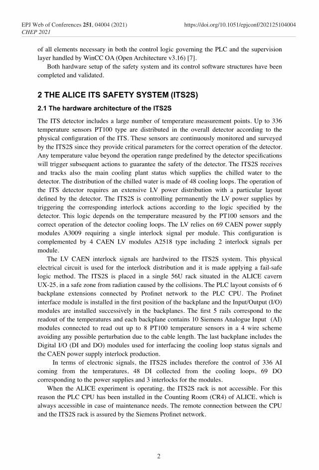
The PT100 sensors wires have been grouped and distributed in a patch panel at the detector side and routed from the detector up to the ITS2S rack in multi-conductor 25 twisted pair shielded cables with a predeÞned pattern. This cable has a maximum capacityfor 12 PT100 sensors in a 4 wires connection. Each cable is terminated with a Sub-D 50 pin male connector at the ITS2S rack.
Several cables were routed up to the rack for a total amount of 336 PT100 temperature sensors. Finally a dedicated interface has been produced in order to simplify the connection and the routing between the cables from the detector and the PLC analogue input modules.
Fig. 1. Schematic view of the ITS2S architecture.
2.2 The software structure of the ITS2S
S7-1500 PLCs are integrated with the TIA (Totally Integrated Automation v16) portal [8] provided by SIEMENS. The TIA portal is an engineering framework that optimises all operational machine tasks and processes routines. It intends to harmonise heterogeneous engineering tools and combine them into one common infrastructure. In addition, the TIA framework integrates the parameters setup of the drivers and networks and the programming of fail safe applications.
The TIA framework includes the entire program range of STEP7. This includes the engineering tools for controls and peripherals as the S7-1500 PLC and it also supports the WinCC OA based SCADA (Supervisory Control And Data Acquisition) tool for supervision. The connection between the S7-1500 PLC and WINCC OA is achieved with the S7 driver supported by both systems.
3
EPJ Web of Conferences 251, 04004 (2021) https://doi.org/10.1051/epjconf/202125104004CHEP 2021
The development of the ITS2S control software for the PLC has followed the CERN control system standards provided by UNICOS, which also includes the connection to the WinCC OA platform. In particular, the UNICOS-CPC package is a CERN made framework to developing industrial control applications. It offers automatic generation tools for the coding based on an objects structure.
UNICOS-CPC includes the UAB tool responsible of the creation of CPC applications. Using as input a speciÞcation Þle (written in an Excel/XML format) provided by the project responsible, it automatically creates the instances and the logic supporting the project. The Þle structure is also standardised and it contains all UNICOS-CPC objects which will conform the logic of the project.
The ITS2S WINCC OA project is hosted in a dedicated server in the CERN Technical Network (TN) and connected to the Oracle Central databases used to store/retrieve conÞguration parameters and to archive system and detector conditions data. The user interface for operators and experts can be started remotely to control the system. Figure 1 shows the ITS2S safety system structure.
The integration of the ITS2S with the ITS DCS (Detector Control System responsible of the overall monitoring and control of the detector) is established through DIP (Data Interchanged Protocol) [9]. All the data process are published by WINCC OA in the TN and the ITS DCS subscribes all the data in the ALICE detector network and in the ALICE DCS Finite State Machine mechanism [10], allowing the operators to monitor and perform a pre-deÞned set of actions for the ITS detector subsystems. A three-level role-based access control allows a clear deÞnition of views and actions that can be accessed by experts, operators or non-authenticated users.
3 FORMALISATION OF THE ITS2S PROJECT
Following the standard UNICOS-CPC terminology used in ITS2S, the electronic signals mentioned in the subsection 2.1 are I/O “objects”. The logic integrating these objects is deÞned through both the Þeld objects, which model the physical Þeld equipment and the control objects, which declare the control actions, the alarms and the interlocks.
The declaration of all these objects and their interconnections are included in a speciÞcation Þle based on predeÞned templates and distributed in pages for each object category. This Þle includes the particular speciÞcations of the system and it is the Þrst step to complete towards the setup of the project.
3.1 The logic specifications of the ITS2S project
The ITS2S safety conditions provided by ALICE are distributed in code blocks involving temperature threshold conditions for the AIs, status of the DIs and associated interlock values set through the DOs. These blocks are deÞned following this structure:
IF ((TT2000 < HH AND TT2000>LL) AND(TT2001<HH AND TT2001>LL) AND
FS0110 =1 AND FS0120 = 1)) THEN DO12065=1 (1)
4
EPJ Web of Conferences 251, 04004 (2021) https://doi.org/10.1051/epjconf/202125104004CHEP 2021
The development of the ITS2S control software for the PLC has followed the CERN control system standards provided by UNICOS, which also includes the connection to the WinCC OA platform. In particular, the UNICOS-CPC package is a CERN made framework to developing industrial control applications. It offers automatic generation tools for the coding based on an objects structure.
UNICOS-CPC includes the UAB tool responsible of the creation of CPC applications. Using as input a speciÞcation Þle (written in an Excel/XML format) provided by the project responsible, it automatically creates the instances and the logic supporting the project. The Þle structure is also standardised and it contains all UNICOS-CPC objects which will conform the logic of the project.
The ITS2S WINCC OA project is hosted in a dedicated server in the CERN Technical Network (TN) and connected to the Oracle Central databases used to store/retrieve conÞguration parameters and to archive system and detector conditions data. The user interface for operators and experts can be started remotely to control the system. Figure 1 shows the ITS2S safety system structure.
The integration of the ITS2S with the ITS DCS (Detector Control System responsible of the overall monitoring and control of the detector) is established through DIP (Data Interchanged Protocol) [9]. All the data process are published by WINCC OA in the TN and the ITS DCS subscribes all the data in the ALICE detector network and in the ALICE DCS Finite State Machine mechanism [10], allowing the operators to monitor and perform a pre-deÞned set of actions for the ITS detector subsystems. A three-level role-based access control allows a clear deÞnition of views and actions that can be accessed by experts, operators or non-authenticated users.
3 FORMALISATION OF THE ITS2S PROJECT
Following the standard UNICOS-CPC terminology used in ITS2S, the electronic signals mentioned in the subsection 2.1 are I/O “objects”. The logic integrating these objects is deÞned through both the Þeld objects, which model the physical Þeld equipment and the control objects, which declare the control actions, the alarms and the interlocks.
The declaration of all these objects and their interconnections are included in a speciÞcation Þle based on predeÞned templates and distributed in pages for each object category. This Þle includes the particular speciÞcations of the system and it is the Þrst step to complete towards the setup of the project.
3.1 The logic specifications of the ITS2S project
The ITS2S safety conditions provided by ALICE are distributed in code blocks involving temperature threshold conditions for the AIs, status of the DIs and associated interlock values set through the DOs. These blocks are deÞned following this structure:
IF ((TT2000 < HH AND TT2000>LL) AND(TT2001<HH AND TT2001>LL) AND
FS0110 =1 AND FS0120 = 1)) THEN DO12065=1 (1)
In this example, digits are used to declare the different sensors, “TT” has been used to refer to AIs and “FS” represents DIs. In addition, “HH” corresponds the upper alarm threshold for temperatures (set to 30C), while “LL” is assigned to the lower threshold value (set to 10C). These alarms thresholds are Þelds declared in the Analog Alarm page of the speciÞcation Þle. ITS will operate between 293 K (ambient temperature in the cavern) and 300 K. The temperature thresholds applied in ITS2S have been established as conservative ranges. The full standard logic of the project is based on repetitive blocks connecting and combining all I/O signals according to the layout of the system. This logic is deÞned in the speciÞcations Þle using the corresponding UNICOS objects.
The logic also includes both a set of blocks declaring interlock conditions for the cooling loops only and speciÞc back-bias interlocks. Finally the system is globally protected through a full system interlock (DI based).
UAB enables the coding automation through speciÞc plug-ins [11], which create and set both the standard objects and the PLC logic. They also deÞne the objects that will be imported afterwards to the WinCC OA toolkit enabling the supervision of the project.
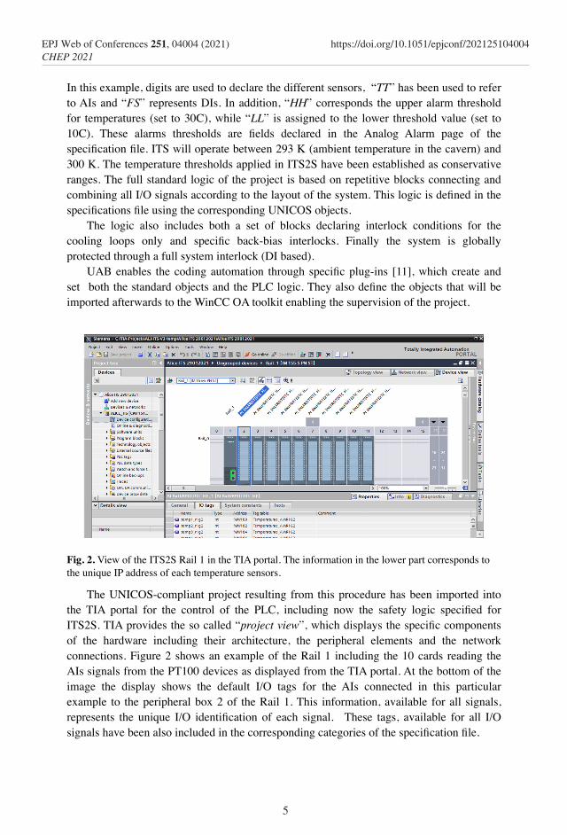
Fig. 2. View of the ITS2S Rail 1 in the TIA portal. The information in the lower part corresponds to the unique IP address of each temperature sensors.
The UNICOS-compliant project resulting from this procedure has been imported into the TIA portal for the control of the PLC, including now the safety logic speciÞed for ITS2S. TIA provides the so called “project view”, which displays the speciÞc components of the hardware including their architecture, the peripheral elements and the network connections. Figure 2 shows an example of the Rail 1 including the 10 cards reading the AIs signals from the PT100 devices as displayed from the TIA portal. At the bottom of the image the display shows the default I/O tags for the AIs connected in this particular example to the peripheral box 2 of the Rail 1. This information, available for all signals, represents the unique I/O identiÞcation of each signal. These tags, available for all I/O signals have been also included in the corresponding categories of the speciÞcation Þle.
5
EPJ Web of Conferences 251, 04004 (2021) https://doi.org/10.1051/epjconf/202125104004CHEP 2021
4 THE SUPERVISION OF ITS2S FROM WINCC OA
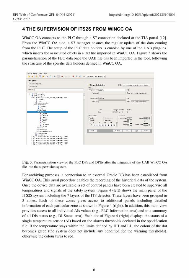
WinCC OA connects to the PLC through a S7 connection declared at the TIA portal [12]. From the WinCC OA side, a S7 manager ensures the regular update of the data coming from the PLC. The setup of the PLC data holders is enabled by one of the UAB plug-ins, which inserts the associated objets in a .txt Þle imported in WinCC OA. Figure 3 shows the parametrisation of the PLC data once the UAB Þle has been imported in the tool, following the structure of the speciÞc data holders deÞned in WinCC OA.
Fig. 3. Parametrisation view of the PLC DPs and DPEs after the migration of the UAB WinCC OA Þle into the supervision system.
For archiving purposes, a connection to an external Oracle DB has been established from WinCC OA. This usual procedure enables the recording of the historical data of the system. Once the device data are available, a set of control panels have been created to supervise all temperatures and signals of the safety system. Figure 4 (left) shows the main panel of the ITS2S system including the 7 layers of the ITS detector. These layers have been grouped in 3 zones. Each of these zones gives access to additional panels including detailed information of each particular zone as shown in Figure 4 (right). In addition, this main view provides access to all individual AIs values (e.g., PLC Information area) and to a summary of all DIs status (e.g., DI Status area). Each dot of Figure 4 (right) displays the status of a single temperature sensor (AI) based on the alarms thresholds declared in the speciÞcation Þle. If the temperature stays within the limits deÞned by HH and LL, the colour of the dot becomes green (the system does not include any condition for the warning thresholds), otherwise the colour turns to red.
6
EPJ Web of Conferences 251, 04004 (2021) https://doi.org/10.1051/epjconf/202125104004CHEP 2021
4 THE SUPERVISION OF ITS2S FROM WINCC OA
WinCC OA connects to the PLC through a S7 connection declared at the TIA portal [12]. From the WinCC OA side, a S7 manager ensures the regular update of the data coming from the PLC. The setup of the PLC data holders is enabled by one of the UAB plug-ins, which inserts the associated objets in a .txt Þle imported in WinCC OA. Figure 3 shows the parametrisation of the PLC data once the UAB Þle has been imported in the tool, following the structure of the speciÞc data holders deÞned in WinCC OA.
Fig. 3. Parametrisation view of the PLC DPs and DPEs after the migration of the UAB WinCC OA Þle into the supervision system.
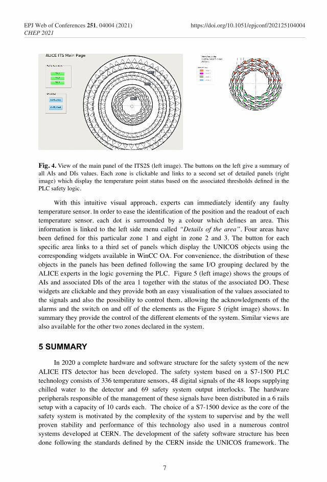
For archiving purposes, a connection to an external Oracle DB has been established from WinCC OA. This usual procedure enables the recording of the historical data of the system. Once the device data are available, a set of control panels have been created to supervise all temperatures and signals of the safety system. Figure 4 (left) shows the main panel of the ITS2S system including the 7 layers of the ITS detector. These layers have been grouped in 3 zones. Each of these zones gives access to additional panels including detailed information of each particular zone as shown in Figure 4 (right). In addition, this main view provides access to all individual AIs values (e.g., PLC Information area) and to a summary of all DIs status (e.g., DI Status area). Each dot of Figure 4 (right) displays the status of a single temperature sensor (AI) based on the alarms thresholds declared in the speciÞcation Þle. If the temperature stays within the limits deÞned by HH and LL, the colour of the dot becomes green (the system does not include any condition for the warning thresholds), otherwise the colour turns to red.
Fig. 4. View of the main panel of the ITS2S (left image). The buttons on the left give a summary of all AIs and DIs values. Each zone is clickable and links to a second set of detailed panels (right image) which display the temperature point status based on the associated thresholds deÞned in the PLC safety logic.
With this intuitive visual approach, experts can immediately identify any faulty temperature sensor. In order to ease the identiÞcation of the position and the readout of each temperature sensor, each dot is surrounded by a colour which deÞnes an area. This information is linked to the left side menu called “Details of the area”. Four areas have been deÞned for this particular zone 1 and eight in zone 2 and 3. The button for each speciÞc area links to a third set of panels which display the UNICOS objects using the corresponding widgets available in WinCC OA. For convenience, the distribution of these objects in the panels has been deÞned following the same I/O grouping declared by the ALICE experts in the logic governing the PLC. Figure 5 (left image) shows the groups of AIs and associated DIs of the area 1 together with the status of the associated DO. These widgets are clickable and they provide both an easy visualisation of the values associated to the signals and also the possibility to control them, allowing the acknowledgments of the alarms and the switch on and off of the elements as the Figure 5 (right image) shows. In summary they provide the control of the different elements of the system. Similar views are also available for the other two zones declared in the system.
5 SUMMARY
In 2020 a complete hardware and software structure for the safety system of the new ALICE ITS detector has been developed. The safety system based on a S7-1500 PLC technology consists of 336 temperature sensors, 48 digital signals of the 48 loops supplying chilled water to the detector and 69 safety system output interlocks. The hardware peripherals responsible of the management of these signals have been distributed in a 6 rails setup with a capacity of 10 cards each. The choice of a S7-1500 device as the core of the safety system is motivated by the complexity of the system to supervise and by the well proven stability and performance of this technology also used in a numerous control systems developed at CERN. The development of the safety software structure has been done following the standards deÞned by the CERN inside the UNICOS framework. The
7
EPJ Web of Conferences 251, 04004 (2021) https://doi.org/10.1051/epjconf/202125104004CHEP 2021
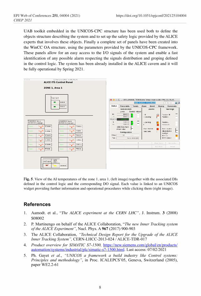
UAB toolkit embedded in the UNICOS-CPC structure has been used both to deÞne the objects structure describing the system and to set up the safety logic provided by the ALICE experts that involves these objects. Finally a complete set of panels have been created into the WinCC OA structure, using the parameters provided by the UNICOS-CPC framework. These panels allow for an easy access to the I/O signals of the system and enable a fast identiÞcation of any possible alarm respecting the signals distribution and groping deÞned in the control logic. The system has been already installed in the ALICE cavern and it will be fully operational by Spring 2021.
Fig. 5. View of the AI temperatures of the zone 1, area 1, (left image) together with the associated DIs deÞned in the control logic and the corresponding DO signal. Each value is linked to an UNICOS widget providing further information and operational procedures while clicking them (right image).
References1. Aamodt. et al., “The ALICE experiment at the CERN LHC”, J. Instrum. 3 (2008)
S08002 2. P. Martinengo on behalf of the ALICE Collaboration, “The new Inner Tracking system
of the ALICE Experiment”, Nucl. Phys. A 967 (2017) 900-903 3. The ALICE Collaboration, “Technical Design Report for the Upgrade of the ALICE
Inner Tracking System”, CERN-LHCC-2013-024 / ALICE-TDR-017 4. Product overview for SIMATIC S7-1500, https://new.siemens.com/global/en/products/
automation/systems/industrial/plc/simatic-s7-1500.html. Last access: 07/02/2021 5. Ph. Gayet et al., “UNICOS a framework a build industry like Control systems:
Principles and methodology”, in Proc. ICALEPCS’05, Geneva, Switzerland (2005), paper WE2.2-61
8
EPJ Web of Conferences 251, 04004 (2021) https://doi.org/10.1051/epjconf/202125104004CHEP 2021
UAB toolkit embedded in the UNICOS-CPC structure has been used both to deÞne the objects structure describing the system and to set up the safety logic provided by the ALICE experts that involves these objects. Finally a complete set of panels have been created into the WinCC OA structure, using the parameters provided by the UNICOS-CPC framework. These panels allow for an easy access to the I/O signals of the system and enable a fast identiÞcation of any possible alarm respecting the signals distribution and groping deÞned in the control logic. The system has been already installed in the ALICE cavern and it will be fully operational by Spring 2021.
Fig. 5. View of the AI temperatures of the zone 1, area 1, (left image) together with the associated DIs deÞned in the control logic and the corresponding DO signal. Each value is linked to an UNICOS widget providing further information and operational procedures while clicking them (right image).
References1. Aamodt. et al., “The ALICE experiment at the CERN LHC”, J. Instrum. 3 (2008)
S08002 2. P. Martinengo on behalf of the ALICE Collaboration, “The new Inner Tracking system
of the ALICE Experiment”, Nucl. Phys. A 967 (2017) 900-903 3. The ALICE Collaboration, “Technical Design Report for the Upgrade of the ALICE
Inner Tracking System”, CERN-LHCC-2013-024 / ALICE-TDR-017 4. Product overview for SIMATIC S7-1500, https://new.siemens.com/global/en/products/
automation/systems/industrial/plc/simatic-s7-1500.html. Last access: 07/02/2021 5. Ph. Gayet et al., “UNICOS a framework a build industry like Control systems:
Principles and methodology”, in Proc. ICALEPCS’05, Geneva, Switzerland (2005), paper WE2.2-61
6. J. Ortola Vidal, “UNICOS-CPC 6, PLC architecture on Siemens S7”. http://unicos.web.cern.ch/unicos-cpc-documentation
7. SIMATIC WinCC Open Architecture Portal: http://winccoa.com. Last access 02/06/2021
8. “The TIA selection tool”, https://new.siemens.com/global/en/products/automation/topic-areas/tia/tia-selection-tool.html. Last access 11/02/2021
9. “The Data Interchange Protocol”, https://readthedocs.web.cern.ch/display/ICKB/DIP+and+DIM. Last access 06/05/2021
10. C. Gaspar, ”The Finite State Machine Toolkit of The JCOP Framework”, http://indico.cern.ch/getFile.py/access?contribId=s1t4&resId=0&materialId=0&confId=a04 1114, 2004
11. J. Fernandez Cortes, “Creation of a Siemens TIA-Portal UNICOS-CPC 6 application”. CERN EDMS document: 1228441
12. “UNICOS-WinCC OA Documentation”, https://unicos.web.cern.ch/unicos-wincc-oa-documentation. Last access 05/10/2020
9
EPJ Web of Conferences 251, 04004 (2021) https://doi.org/10.1051/epjconf/202125104004CHEP 2021