Embed Size (px)
Citation preview
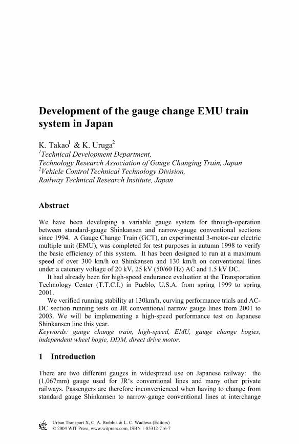
Development of the gauge change EMU train system in Japan
1 2
1Technical Development Department, Technology Research Association of Gauge Changing Train, Japan 2Vehicle Control Technical Technology Division, Railway Technical Research Institute, Japan
Abstract
We have been developing a variable gauge system for through-operation between standard-gauge Shinkansen and narrow-gauge conventional sections since 1994. A Gauge Change Train (GCT), an experimental 3-motor-car electric multiple unit (EMU), was completed for test purposes in autumn 1998 to verify the basic efficiency of this system. It has been designed to run at a maximum speed of over 300 km/h on Shinkansen and 130 km/h on conventional lines under a catenary voltage of 20 kV, 25 kV (50/60 Hz) AC and 1.5 kV DC. It had already been for high-speed endurance evaluation at the Transportation Technology Center (T.T.C.I.) in Pueblo, U.S.A. from spring 1999 to spring 2001. We verified running stability at 130km/h, curving performance trials and AC-DC section running tests on JR conventional narrow gauge lines from 2001 to 2003. We will be implementing a high-speed performance test on Japanese Shinkansen line this year. Keywords: gauge change train, high-speed, EMU, gauge change bogies, independent wheel bogie, DDM, direct drive motor.
1 Introduction
There are two different gauges in widespread use on Japanese railway: the (1,067mm) gauge used for JR‘s conventional lines and many other private railways. Passengers are therefore inconvenienced when having to change from standard gauge Shinkansen to narrow-gauge conventional lines at interchange
Urban Transport X, C. A. Brebbia & L. C. Wadhwa (Editors)© 2004 WIT Press, www.witpress.com, ISBN 1-85312-716-7
K. Takao & K. Uruga
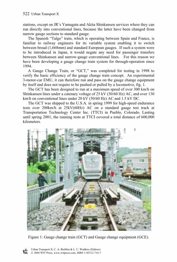
stations, except on JR‘s Yamagata and Akita Shinkansen services where they can run directly into conventional lines, because the latter have been changed from narrow gauge sections to standard gauge. The Spanish “Talgo” train, which is operating between Spain and France, is familiar to railway engineers for its variable system enabling it to switch between broad (1,668mm) and standard European gauges. If such a system were to be introduced in Japan, it would negate any need for passenger transfers between Shinkansen and narrow-gauge conventional lines. For this reason we have been developing a gauge change train system for through-operation since 1994. A Gauge Change Train, or “GCT,” was completed for testing in 1998 to verify the basic efficiency of the gauge change train concept. An experimental 3-motor-car EMU, it can therefore run and pass on the gauge change equipment by itself and does not require to be pushed or pulled by a locomotive, fig. 1. The GCT has been designed to run at a maximum speed of over 300 km/h on Shinkansen lines under a catenary voltage of 25 kV (50/60 Hz) AC, and over 130 km/h on conventional lines under 20 kV (50/60 Hz) AC and 1.5 kV DC. The GCT was shipped to the U.S.A. in spring 1999 for high-speed endurance tests over 200km/h at 25kV(60Hz) AC on a standard gauge test track at Transportation Technology Center Inc. (TTCI) in Pueblo, Colorado. Lasting until spring 2001, the running tests at TTCI covered a total distance of 600,000 kilometers.
Figure 1: Gauge change train (GCT) and Gauge change equipment (GCE).
Urban Transport X, C. A. Brebbia & L. C. Wadhwa (Editors)© 2004 WIT Press, www.witpress.com, ISBN 1-85312-716-7
522 Urban Transport X
After having been shipped back to Japan, the GCT was reconfigured for performance tests on Japanese standard gauge Shinkansen and narrow-gauge conventional lines. A number of performance tests were conducted with the GCT on both JR‘s Nippo Line in Kyushu and Yosan Line in Shikoku, and at JR West’s Shin-shimonoseki test facilities from autumn 2001 to spring 2003.
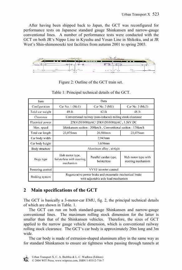
Table 1: Principal technical details of the GCT.
2 Main specifications of the GCT
The GCT is basically a 3-motor-car EMU, fig. 2, the principal technical details of which are shown in Table. 1. The GCT can run on both standard-gauge Shinkansen and narrow-gauge conventional lines. The maximum rolling stock dimension for the latter is smaller than that of the Shinkansen vehicles. Therefore, the sizes of GCT applied to the narrow gauge vehicle dimension, which is conventional railway rolling stock clearance. The GCT‘s car body is approximately 20m long and 3m wide. The car body is made of extrusion-shaped aluminum alloy in the same way as for standard Shinkansen to ensure air tightness when passing through tunnels at
Figure 2: Outline of the GCT train set.
Table 1: Principal technical details of the GCT.
Figure 2: Outline of the GCT train set.
Urban Transport X, C. A. Brebbia & L. C. Wadhwa (Editors)© 2004 WIT Press, www.witpress.com, ISBN 1-85312-716-7
Urban Transport X 523
high speed, with a number of aluminum parts and elements being welded. Each leading car has a head cover made of CFRP and is fitted with a coupler. The GCT does not have service equipment such as passenger seats or baggage shelves, but it is equipped with air conditioning for the crew. In place of passenger seats, a number of racks have been installed for performance test measuring instruments. Some equipment – a brake controller unit (BCU), blower motors for driving motors (MMBM), a line breaker (LB) box, a vacuum circuit breaker (VCB), an AC-DC changer, arresters etc.- are installed in the passenger cabin. Two pantographs, both connected by an extra-high-voltage cable, are installed on top of the cars. One is the high-speed Shinkansen pantograph on car No.2, and the other a universal 20kV AC-1.5kV DC pantograph for conventional lines on car No.3. A power circuit, auxiliary circuit equipment and subsystems are arranged underneath the body frame at the following places: -
• Main transformer (MTr) : car No.1 (Mc1) • Auxiliary static inverters (SIV) : car Nos.2 (M1) and 3 (Mc2) • Air compressor (CP): car No.3 (Mc2) • Power converter/inverter units (CI) : each car • Load contactors (LC) : each car
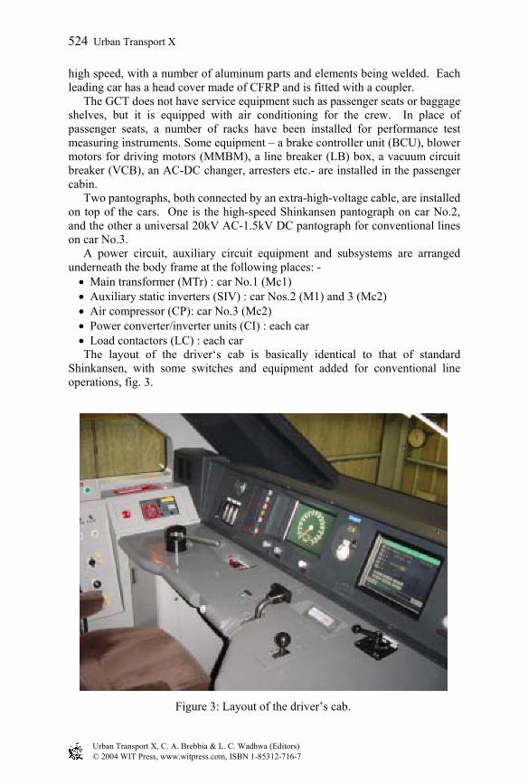
The layout of the driver‘s cab is basically identical to that of standard Shinkansen, with some switches and equipment added for conventional line operations, fig. 3.
Figure 3: Layout of the driver’s cab.
Urban Transport X, C. A. Brebbia & L. C. Wadhwa (Editors)© 2004 WIT Press, www.witpress.com, ISBN 1-85312-716-7
524 Urban Transport X
3 Gauge change bogies
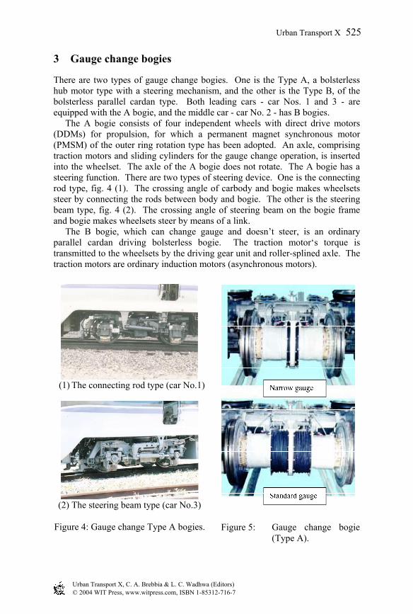
There are two types of gauge change bogies. One is the Type A, a bolsterless hub motor type with a steering mechanism, and the other is the Type B, of the bolsterless parallel cardan type. Both leading cars - car Nos. 1 and 3 - are equipped with the A bogie, and the middle car - car No. 2 - has B bogies. The A bogie consists of four independent wheels with direct drive motors (DDMs) for propulsion, for which a permanent magnet synchronous motor (PMSM) of the outer ring rotation type has been adopted. An axle, comprising traction motors and sliding cylinders for the gauge change operation, is inserted into the wheelset. The axle of the A bogie does not rotate. The A bogie has a steering function. There are two types of steering device. One is the connecting rod type, fig. 4 (1). The crossing angle of carbody and bogie makes wheelsets steer by connecting the rods between body and bogie. The other is the steering beam type, fig. 4 (2). The crossing angle of steering beam on the bogie frame and bogie makes wheelsets steer by means of a link. The B bogie, which can change gauge and doesn’t steer, is an ordinary parallel cardan driving bolsterless bogie. The traction motor‘s torque is transmitted to the wheelsets by the driving gear unit and roller-splined axle. The traction motors are ordinary induction motors (asynchronous motors).
(2) The steering beam type (car No.3)
Figure 4: Gauge change Type A bogies. Figure 5: Gauge change bogie
(Type A).
(1) The connecting rod type (car No.1)
Urban Transport X, C. A. Brebbia & L. C. Wadhwa (Editors)© 2004 WIT Press, www.witpress.com, ISBN 1-85312-716-7
Urban Transport X 525
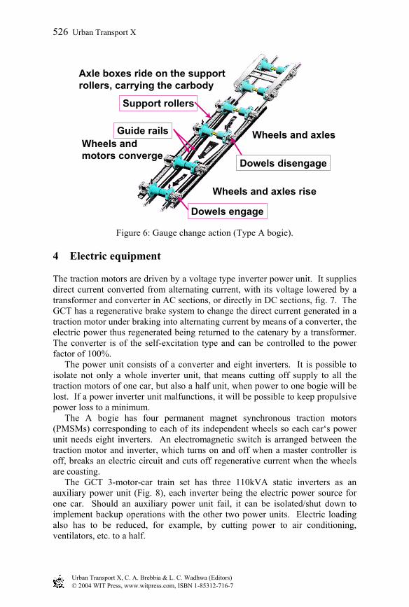
Figure 6: Gauge change action (Type A bogie).
4 Electric equipment
The traction motors are driven by a voltage type inverter power unit. It supplies direct current converted from alternating current, with its voltage lowered by a transformer and converter in AC sections, or directly in DC sections, fig. 7. The GCT has a regenerative brake system to change the direct current generated in a traction motor under braking into alternating current by means of a converter, the electric power thus regenerated being returned to the catenary by a transformer. The converter is of the self-excitation type and can be controlled to the power factor of 100%. The power unit consists of a converter and eight inverters. It is possible to isolate not only a whole inverter unit, that means cutting off supply to all the traction motors of one car, but also a half unit, when power to one bogie will be lost. If a power inverter unit malfunctions, it will be possible to keep propulsive power loss to a minimum. The A bogie has four permanent magnet synchronous traction motors (PMSMs) corresponding to each of its independent wheels so each car‘s power unit needs eight inverters. An electromagnetic switch is arranged between the traction motor and inverter, which turns on and off when a master controller is off, breaks an electric circuit and cuts off regenerative current when the wheels are coasting. The GCT 3-motor-car train set has three 110kVA static inverters as an auxiliary power unit (Fig. 8), each inverter being the electric power source for one car. Should an auxiliary power unit fail, it can be isolated/shut down to implement backup operations with the other two power units. Electric loading also has to be reduced, for example, by cutting power to air conditioning, ventilators, etc. to a half.
Support rollers
Guide rails
Axle boxes ride on the supportrollers, carrying the carbody
Dowels disengage
Wheels andmotors converge
Wheels and axles rise
Dowels engage
Urban Transport X, C. A. Brebbia & L. C. Wadhwa (Editors)© 2004 WIT Press, www.witpress.com, ISBN 1-85312-716-7
526 Urban Transport X
Wheels and axles
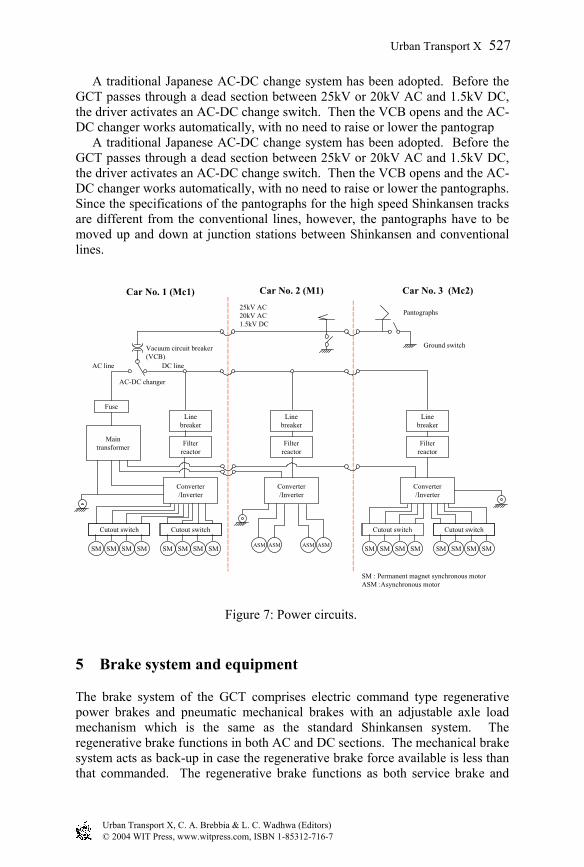
A traditional Japanese AC-DC change system has been adopted. Before the GCT passes through a dead section between 25kV or 20kV AC and 1.5kV DC, the driver activates an AC-DC change switch. Then the VCB opens and the AC-DC changer works automatically, with no need to raise or lower the pantograp A traditional Japanese AC-DC change system has been adopted. Before the GCT passes through a dead section between 25kV or 20kV AC and 1.5kV DC, the driver activates an AC-DC change switch. Then the VCB opens and the AC-DC changer works automatically, with no need to raise or lower the pantographs. Since the specifications of the pantographs for the high speed Shinkansen tracks are different from the conventional lines, however, the pantographs have to be moved up and down at junction stations between Shinkansen and conventional lines.
5 Brake system and equipment
The brake system of the GCT comprises electric command type regenerative power brakes and pneumatic mechanical brakes with an adjustable axle load mechanism which is the same as the standard Shinkansen system. The regenerative brake functions in both AC and DC sections. The mechanical brake system acts as back-up in case the regenerative brake force available is less than that commanded. The regenerative brake functions as both service brake and
Cutout switch
SM SM SM SM
Cutout switch
SM SM SM SM ASM ASM ASM ASM
Converter/Inverter
Converter/Inverter
Maintransformer
Linebreaker
Filterreactor
Linebreaker
Filterreactor
Fuse
Cutout switch
SM SM SM SM
Cutout switch
SM SM SM SM
Converter/Inverter
Linebreaker
Filterreactor
AC line
AC-DC changer
Vacuum circuit breaker(VCB)
DC line
25kV AC20kV AC1.5kV DC
Car No. 1 (Mc1) Car No. 2 (M1) Car No. 3 (Mc2)
Ground switch
SM : Permanent magnet synchronous motor ASM :Asynchronous motor
Pantographs
Figure 7: Power circuits.
Urban Transport X, C. A. Brebbia & L. C. Wadhwa (Editors)© 2004 WIT Press, www.witpress.com, ISBN 1-85312-716-7
Urban Transport X 527
emergency brake while in normal operation. Other mechanical brake systems are the urgent brake, which works only on Shinkansen, and the security brake on conventional lines. The brake control systems differ between Shinkansen and conventional lines in their brake patterns, command brake forces, brake control devices, for example and a re-adhesion control system has been adopted for the GCT. The mechanical brake system uses wheel disk brakes, brake force originally being provided by pneumatic pressure and converted into hydraulic pressure by booster cylinder activating hydraulic cylinders to push brake shoes on the brake caliper.
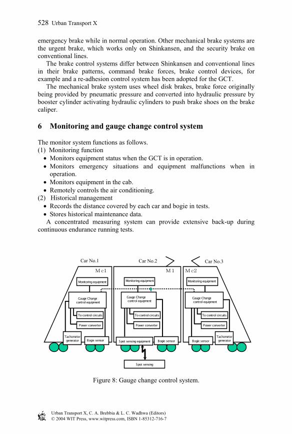
6 Monitoring and gauge change control system
The monitor system functions as follows. (1) Monitoring function
• Monitors equipment status when the GCT is in operation. • Monitors emergency situations and equipment malfunctions when in
operation. • Monitors equipment in the cab. • Remotely controls the air conditioning.
(2) Historical management • Records the distance covered by each car and bogie in tests. • Stores historical maintenance data.
A concentrated measuring system can provide extensive back-up during continuous endurance running tests.
Monitoring equipment
Gauge Change control equipment
To control circuits
Power converter
Mc1 M1 Mc2
Spot sensing
Spot sensing equipment Bogie sensor Bogie sensorTachometergenerator
Tachometergenerator
To control circuitsTo control circuits
Power converterPower converter
Gauge Change control equipment
Gauge Change control equipment
Bogie sensor
Car No.1 Car No.3Car No.2
Monitoring equipmentMonitoring equipment
Figure 8: Gauge change control system.
Urban Transport X, C. A. Brebbia & L. C. Wadhwa (Editors)© 2004 WIT Press, www.witpress.com, ISBN 1-85312-716-7
528 Urban Transport X
A gauge change control system is included in the monitor system. The GCT has to pass along a special track equipped with gauge change equipment (GCE) before changing between standard and narrow gauges. While running on the GCE track, the GCT must undergo special motor safety checks to ensure a safe transition and prevent mechanical failure. This system functions as follows: -
• Monitors the actual conditions for changing gauges. • Controls and limits the train speed on passing the GCE. • Automatically stops the train on the GCE in the event of a system
malfunction during the operation.
7 Running tests
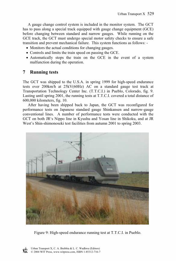
The GCT was shipped to the U.S.A. in spring 1999 for high-speed endurance tests over 200km/h at 25kV(60Hz) AC on a standard gauge test track at Transportation Technology Center Inc. (T.T.C.I.) in Pueblo, Colorado, fig. 9. Lasting until spring 2001, the running tests at T.T.C.I. covered a total distance of 600,000 kilometers, fig. 10. After having been shipped back to Japan, the GCT was reconfigured for performance tests on Japanese standard gauge Shinkansen and narrow-gauge conventional lines. A number of performance tests were conducted with the GCT on both JR‘s Nippo line in Kyushu and Yosan line in Shikoku, and at JR West’s Shin-shimonoseki test facilities from autumn 2001 to spring 2003.
Figure 9: High-speed endurance running test at T.T.C.I. in Pueblo.
Urban Transport X, C. A. Brebbia & L. C. Wadhwa (Editors)© 2004 WIT Press, www.witpress.com, ISBN 1-85312-716-7
Urban Transport X 529
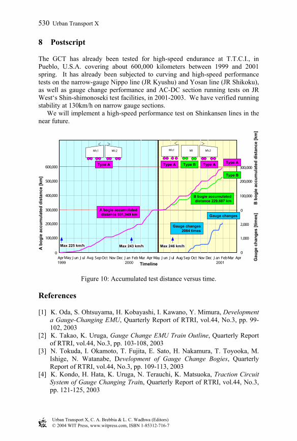
8 Postscript
The GCT has already been tested for high-speed endurance at T.T.C.I., in Pueblo, U.S.A. covering about 600,000 kilometers between 1999 and 2001 spring. It has already been subjected to curving and high-speed performance tests on the narrow-gauge Nippo line (JR Kyushu) and Yosan line (JR Shikoku), as well as gauge change performance and AC-DC section running tests on JR West‘s Shin-shimonoseki test facilities, in 2001-2003. We have verified running stability at 130km/h on narrow gauge sections. We will implement a high-speed performance test on Shinkansen lines in the near future.
Figure 10: Accumulated test distance versus time.
References
[1] K. Oda, S. Ohtsuyama, H. Kobayashi, I. Kawano, Y. Mimura, Development a Gauge-Changing EMU, Quarterly Report of RTRI, vol.44, No.3, pp. 99-102, 2003
[2] K. Takao, K. Uruga, Gauge Change EMU Train Outline, Quarterly Report of RTRI, vol.44, No.3, pp. 103-108, 2003
[3] N. Tokuda, I. Okamoto, T. Fujita, E. Sato, H. Nakamura, T. Toyooka, M. Ishige, N. Watanabe, Development of Gauge Change Bogies, Quarterly Report of RTRI, vol.44, No.3, pp. 109-113, 2003
[4] K. Kondo, H. Hata, K. Uruga, N. Terauchi, K. Matsuoka, Traction Circuit System of Gauge Changing Train, Quarterly Report of RTRI, vol.44, No.3, pp. 121-125, 2003
0
100,000
200,000
300,000
400,000
500,000
600,000
AprMay J un J ul Aug SepOct Nov Dec J an Feb Mar Apr May J un J ul Aug Sep Oct Nov Dec J an FebMar Apr0
1,000
2,000
Max 225 km/h
1999 2000 2001
Gauge changes
Gauge changes2084 times
0
100,000
200,000
300,000
B bogie accumulateddistance 229,687 km
Type B
M'c2M'c1
Type A
M1 M'c2M'c1
Type A Type B Type A Type A
A bogie accumulateddistance 591,949 km
Gau
ge c
hang
es [t
imes
]B
bog
ie a
ccum
ulat
ed d
ista
nce
[km
]
A b
ogie
acc
umul
ated
dis
tanc
e [k
m]
Timeline
Max 243 km/h Max 246 km/h
Urban Transport X, C. A. Brebbia & L. C. Wadhwa (Editors)© 2004 WIT Press, www.witpress.com, ISBN 1-85312-716-7
530 Urban Transport X