Embed Size (px)
Citation preview
Development of Steam Turbine Inlet Control Valve for Supercritical Pressure
at Siemens Industrial Turbomachinery AB
Felix Sors & Patrik Holm
Machine Design
Master Thesis
Department of Management and Engineering
LIU-IEI-TEK-A--10/00838--SE

Abstract The development in the steam turbine business is heading for applications with much higher steam parameters since this enables a raised efficiency. Steam parameters refer to the pressure and the temperature of the steam. The aim of this study was to generate concepts for steam turbine inlet control valves designed for higher pressure and temperature in comparison with the present design. Future steam power plants using solar energy, based on tower technology, request this kind of performance and are an important potential market.
This master thesis at Linköping University has been written in collaboration with Siemens Industrial Turbomachinery AB. The performed work has incorporated literature studies, functional analysis and solid mechanics analysis, flow analysis, evaluation of sealings and cup springs and development of the dimensioning data for the future control valve. The aim was to find a design concept that sustains the new and higher steam parameters and is tolerant concerning vibrations.
A systematical way to work has been applied during the project and a detailed planning was continuously followed and adjusted. Major methods used were product design specification, quality function deployment, morphological matrices, decision matrices and failure mode and effect analysis. Important programs used during the project were Pro/ENGINEER, MATLAB, FloEFD and MS Excel.
Today’s valves are dimensioned for much lower performance than the new requirements in terms of pressure and temperature. The main problem for the present design is that the opening and closing forces requirements, with the new higher pressure, get unreasonably large. Therefore were many of the developed concepts equipped with a pressure balancing feature. This feature also gives another desirable result; the vibrations (that is the source of many of the problems with the present design) will also be reduced.
During the early concept development phase, 15 different concepts were generated and after the concept evaluation only three concepts remained. These concepts were further developed in different areas of interest and finally one of the three was chosen to be the winning concept. The new valve design will most likely meet the requirements and has the potential to be refined for even higher pressure for future demands.

Sammanfattning Utvecklingen inom ångturbiner går mot applikationer med mycket högre ångdata eftersom detta möjliggör en ökad effektivitet. Ångdata refererar till ångans tryck och temperatur. Uppgiften var att generera koncept för inloppsreglerventiler (till ångturbiner) dimensionerade för högre tryck och temperatur jämfört med dagens design. Framtida ångkraftverk som drivs av solenergi, så kallade soltorn, efterfrågar denna prestanda och är en viktig framtida marknad.
Detta examensarbete vid Linköpings Universitet har skrivits i samverkan med Siemens Industrial Turbomachinery AB. Det genomförda arbetet har innefattat litteraturstudier, funktionsanalys och hållfasthetsanalys, flödesanalys, utvärdering av tätningar och tallriksfjädrar samt framtagning av dimensioneringsunderlag för den framtida reglerventilen. Målet var att finna ett koncept som klarar av dessa nya och högre ångdata och är tåligt beträffande vibrationer.
Ett systematiskt arbetssätt har anammats under projektet och en detaljerad planering upprättades och uppdaterades kontinuerligt. Viktiga metoder som använts är PDS (Product Design Specification), QFD (Quality Function Deployment), morfologisk matris, relativ beslutsmatris och feleffektanalys. Viktiga program som använts i projektet är Pro/ENGINEER, MATLAB, FloEFD och MS Excel.
Dagens ventiler är dimensionerade för mycket lägre prestanda än de nya kraven kräver i termer av tryck och temperatur. Det huvudsakliga problemet med den nuvarande designen var att kraven på de öppnande och stängande krafterna, med dessa nya ångdata, blir orimligt höga. Därför har många av de framtagna koncepten utrustats med tryckbalanserande funktion. Denna funktion ger också ett annat önskvärt resultat; vibrationerna (som är källan till många problem med dagens design) kommer även de att reduceras.
Under den tidiga konceptutvecklingsfasen genererades 15 olika koncept och efter konceptutvärderingen återstod bara tre. Dessa koncept vidareutvecklades inom olika intressanta områden och slutligen valdes ett av koncepten som det vinnande. Den nya ventildesignen kommer med stor sannolikhet att uppfylla kraven och har potential att förfinas för ännu högre tryck för framtida krav.

Preface We are grateful that we got the opportunity to write our Master of Science thesis at Siemens Industrial Turbomachinery AB in Finspång during the spring term 2010. The company and its product have a great reputation and the project has been a good experience and a worthwhile summary of what we have learned at Linköping University.
The master thesis came into existence when Felix during his summer job requested a project for his master thesis involving the product development process. Magnus proposed this control valve project which had a high priority at Siemens due to customer requests for this product.
The following persons have been important during the project and the writing of the master thesis.
Magnus Hallberg Manager of department DA Siemens Industrial Turbomachinery
Michael Blomqvist Manager of department DAC Siemens Industrial Turbomachinery
Johan Ölvander Professor Department of Management and Engineering Linköping University
Björn Eriksson Doctoral student Department of Management and Engineering Linköping University
We would also like to thank all the personnel at department DA at Siemens and all other employees at Siemens that have been helping us during the project.
Finspång, June 2010
Felix Sors [email protected]
Patrik Holm [email protected]

Table of Contents
1 INTRODUCTION................................................................................................................................1
1.1 BACKGROUND...............................................................................................................................1 1.2 COMPANY PRESENTATION ............................................................................................................1 1.3 BRIEF DESCRIPTION OF A STEAM TURBINE ..................................................................................2 1.4 BRIEF DESCRIPTION OF THE INLET VALVES .................................................................................3 1.5 PROBLEM DESCRIPTION ................................................................................................................4 1.6 LIMITATIONS .................................................................................................................................4 1.7 REPORT LAYOUT...........................................................................................................................5
2 THEORY...............................................................................................................................................7
2.1 STEAM TURBINES..........................................................................................................................7 2.1.1 Isentropic Efficiency of Turbines ............................................................................................9
2.2 STEAM POWER CYCLES ................................................................................................................9 2.2.1 Property Diagram .................................................................................................................10 2.2.2 The Carnot Cycle...................................................................................................................11 2.2.3 The Ideal Rankine Cycle .......................................................................................................12 2.2.4 Increasing the Efficiency when using the Rankine Cycle.....................................................13 2.2.5 The Ideal Reheat Rankine Cycle ...........................................................................................16
2.3 INLET VALVES.............................................................................................................................18 2.3.1 Safety Requirements ..............................................................................................................18 2.3.2 Present Valve Design ............................................................................................................18 2.3.3 Sealing ...................................................................................................................................20 2.3.4 Valve Forces ..........................................................................................................................22 2.3.5 Limitations with the Present Design .....................................................................................23
2.4 MATERIAL...................................................................................................................................24 2.4.1 Material Complexity with Cr Steels ......................................................................................25 2.4.2 Coating of the Material .........................................................................................................26 2.4.3 Future Material for Steam Turbines .....................................................................................27
3 METHOD............................................................................................................................................29
3.1 PRODUCT SPECIFICATION ...........................................................................................................29 3.1.1 Quality Function Deployment ...............................................................................................29 3.1.2 Pairwise Comparison ............................................................................................................31 3.1.3 Product Design Specification................................................................................................32
3.2 CONCEPT GENERATION...............................................................................................................33 3.2.1 Functional Design .................................................................................................................34 3.2.2 Morphological Matrix ...........................................................................................................35
3.3 CONCEPT EVALUATION...............................................................................................................35 3.3.1 Relative Decision Matrix.......................................................................................................36 3.3.2 Optimization with Genetic Algorithm ...................................................................................37 3.3.3 Failure Mode and Effect Analysis.........................................................................................38
4 CONCEPT DEVELOPMENT .........................................................................................................39
4.1 PROJECT SPECIFICATION.............................................................................................................39 4.1.1 Quality Function Deployment ...............................................................................................40
4.2 CONCEPT GENERATION...............................................................................................................42 4.2.1 Pressure Balancing ...............................................................................................................44
4.3 CONCEPT EVALUATION...............................................................................................................46 4.3.1 Computational Fluid Dynamics ............................................................................................46 4.3.2 Relative Decision Matrix.......................................................................................................48
5 FURTHER DEVELOPMENT .........................................................................................................51
5.1 TECHNICAL DESIGN OF CONCEPT 5 ............................................................................................52 5.1.1 New Cup Springs ...................................................................................................................54
5.2 TECHNICAL DESIGN OF CONCEPT 8 ............................................................................................56 5.2.1 Cover Assembly and Force Distribution...............................................................................57
5.3 TECHNICAL DESIGN OF CONCEPT 9 ............................................................................................58 5.3.1 Accumulator Volume .............................................................................................................58 5.3.2 Safety Regarding the Hydraulic Accumulator......................................................................59 5.3.3 Nitrogen Gas Spring..............................................................................................................59
5.4 TECHNICAL DESIGN OF CASTING................................................................................................61 5.4.1 Optimization of Casting Mass...............................................................................................61 5.4.2 Casting Mass versus Pressure Drop.....................................................................................64
5.5 FASTENING OF THE COVER .........................................................................................................66 5.5.1 Divided Ring ..........................................................................................................................66 5.5.2 Threaded Ring .......................................................................................................................67
5.6 FAILURE MODE AND EFFECT ANALYSIS.....................................................................................68
6 RESULTS............................................................................................................................................69
7 DISCUSSION .....................................................................................................................................71
7.1 METHOD CHOICES AND ITS LIMITATIONS....................................................................................71 7.2 LITERATURE LIMITATIONS ..........................................................................................................71 7.3 FUTURE WORK............................................................................................................................72
8 CONCLUSIONS ................................................................................................................................73
9 BIBLIOGRAPHY ..............................................................................................................................75
10 APPENDIX .........................................................................................................................................77
10.1 APPENDIX A: PRODUCT DESIGN SPECIFICATION........................................................................77 10.1.1 Function Limited Requirements .......................................................................................77 10.1.2 Security Requirements ......................................................................................................77 10.1.3 Solid Mechanics and Material Requirements ..................................................................78 10.1.4 Environmental Requirements ...........................................................................................78 10.1.5 Overall Design Requirements ..........................................................................................79
10.2 APPENDIX B: FUNCTION MEANS TREES .....................................................................................80 10.3 APPENDIX C: PROJECT PLANNING ..............................................................................................84 10.4 APPENDIX D: CONCEPTUAL DESIGN...........................................................................................85
10.4.1 Concept 1 ..........................................................................................................................86 10.4.2 Concept 2 ..........................................................................................................................88 10.4.3 Concept 3 ..........................................................................................................................90 10.4.4 Concept 4 ..........................................................................................................................92 10.4.5 Concept 5 ..........................................................................................................................94 10.4.6 Concept 6 ..........................................................................................................................96 10.4.7 Concept 7 ..........................................................................................................................98 10.4.8 Concept 8 ........................................................................................................................100 10.4.9 Concept 9 ........................................................................................................................102 10.4.10 Concept 10 ......................................................................................................................104 10.4.11 Concept 11 ......................................................................................................................106 10.4.12 Concept 12 ......................................................................................................................108 10.4.13 Concept 13 ......................................................................................................................110 10.4.14 Concept 14 ......................................................................................................................112 10.4.15 Concept 15 ......................................................................................................................114
10.5 APPENDIX E: RESULTS FROM CFD CALCULATIONS.................................................................116 10.5.1 Pressure Drop for Concepts 1, 2 and 4 .........................................................................116 10.5.2 Pressure Drop for Concept 3 .........................................................................................116 10.5.3 Pressure Drop for Concepts 5, 9 and 10 .......................................................................117 10.5.4 Pressure Drop for Concept 6 .........................................................................................117 10.5.5 Pressure Drop for Concept 7 .........................................................................................118 10.5.6 Pressure Drop for Concept 8 .........................................................................................118 10.5.7 Pressure Drop for Concept 11 .......................................................................................119 10.5.8 Pressure Drop for Concepts 12 and 13 .........................................................................119 10.5.9 Pressure Drop for Concepts 14 and 15 .........................................................................120
Table of Figures Figure 1.1: Steam turbine design by Heron of Alexandria ............................................. 2
Figure 1.2: Steam turbine power plant setup .................................................................. 3
Figure 1.3: High pressure steam turbine with inlet valves .............................................. 3
Figure 2.1: Radial and axial flow turbine ......................................................................... 7
Figure 2.2: Impulse and reaction stage design ............................................................... 8
Figure 2.3: T-v diagram for a pure substance................................................................. 10
Figure 2.4: P-v and T-s diagrams of the Carnot cycle.................................................... 11
Figure 2.5: The ideal Rankine cycle............................................................................... 12
Figure 2.6: The effect of lowering the condenser pressure ............................................ 13
Figure 2.7: The effect of superheating the steam to higher temperatures .................... 14
Figure 2.8: The effect of increasing the boiler pressure ................................................. 15
Figure 2.9: The supercritical Rankine cycle................................................................... 15
Figure 2.10: The ideal reheat Rankine cycle .................................................................. 16
Figure 2.11: Large low pressure turbine ........................................................................ 17
Figure 2.12: Components in the present control valve................................................... 19
Figure 2.13: Graphite compression packing................................................................... 20
Figure 2.14: Compression of the packing....................................................................... 21
Figure 2.15: Valve forces depending on cone position ................................................ 22
Figure 2.16: The development history of steel alloys for steam turbine components.... 24
Figure 3.1: Quality Function Deployment...................................................................... 30
Figure 3.2: Pairwise comparison of customer requirements .......................................... 31
Figure 3.3: Result of pairwise comparison..................................................................... 32
Figure 3.4: Function means tree ..................................................................................... 34
Figure 3.5: Morphological matrix .................................................................................. 35
Figure 3.6: Relative decision matrix .............................................................................. 36
Figure 3.7: Importance calculated by scaling of the customer requirement priorities ... 36
Figure 3.8: Result for relative decision matrix ............................................................... 37
Figure 4.1: Pairwise comparison .................................................................................... 40
Figure 4.2: Normalized customer requirements ............................................................. 40
Figure 4.3: QFD matrix .................................................................................................. 41
Figure 4.4: Normalized system characteristics priorities ............................................... 41
Figure 4.5: Control steam flow F/M tree........................................................................ 43
Figure 4.6: The 15 concepts ........................................................................................... 44
Figure 4.7: Pressure balancing of concept 5................................................................... 45
Figure 4.8: Pressure balancing of concept 12................................................................. 45
Figure 4.9: Pressure drop for concept 5.......................................................................... 47
Figure 4.10: Pressure drop for concept 12...................................................................... 47
Figure 4.11: First decision matrix .................................................................................. 48
Figure 4.12: Result from the first decision matrix ......................................................... 48
Figure 4.13: Second decision matrix .............................................................................. 49
Figure 4.14: Result from the second decision matrix..................................................... 49
Figure 5.1: Concept 5, 8 and 9 ....................................................................................... 51
Figure 5.2: Cover design for concept 5 with adjustable lower gland pressure............... 53
Figure 5.3: Cover design for concept 5 with non-adjustable lower gland pressure ....... 53
Figure 5.4: Spring characteristic for a stack of cup springs ........................................... 54
Figure 5.5: Modifications on the present servo induced by new cup springs ................ 55
Figure 5.6: Cover design for concept 8 .......................................................................... 56
Figure 5.7: Force distribution for concept 8 ................................................................... 57
Figure 5.8: DADCO gas spring ...................................................................................... 59
Figure 5.9: Gas spring mounted in servo........................................................................ 60
Figure 5.10: Mass model ................................................................................................ 61
Figure 5.11: Intersecting volumes .................................................................................. 62
Figure 5.12: Calculation of the intersecting volumes..................................................... 62
Figure 5.13: Stress concentrations and the optimization variables ................................ 63
Figure 5.14: Smallest and largest versions of concept 8 ................................................ 64
Figure 5.15: Results from the mass optimization for concept 5 and concept 9.............. 65
Figure 5.16: Results from the mass optimization for concept 8..................................... 65
Figure 5.17: Divided ring assembly ............................................................................... 66
Figure 5.18: Loads at divided ring ................................................................................. 66
Figure 5.19: Threaded ring ............................................................................................. 67
Figure 5.20: Loads at threaded ring................................................................................ 67
Figure 5.21: FMEA ........................................................................................................ 68
Figure 6.1: Final version of concept 8............................................................................ 70
Figure 10.1: Control valve F/M tree............................................................................... 80
Figure 10.2: Connection tube-valve-turbine F/M trees .................................................. 81
Figure 10.3: Enclose steam F/M tree.............................................................................. 82
Figure 10.4: Control steam flow F/M tree...................................................................... 83
Figure 10.5: Final Gantt chart ........................................................................................ 84
Figure 10.6: Concept overview ...................................................................................... 85
Figure 10.7: Concept 1 ................................................................................................... 87
Figure 10.8: Concept 2 ................................................................................................... 89
Figure 10.9: Concept 3 ................................................................................................... 91
Figure 10.10: Detail of concept 3 ................................................................................... 91
Figure 10.11: Concept 4 ................................................................................................. 93
Figure 10.12: Concept 5 ................................................................................................. 95
Figure 10.13: Detail of concept 5 ................................................................................... 95
Figure 10.14: Concept 6 ................................................................................................. 97
Figure 10.15: Detail of concept 6 ................................................................................... 97
Figure 10.16: Concept 7 ................................................................................................. 99
Figure 10.17: Detail of concept 7 ................................................................................... 99
Figure 10.18: Concept 8 ............................................................................................... 101
Figure 10.19: Detail of concept 8 ................................................................................. 101
Figure 10.20: Concept 9 ............................................................................................... 103
Figure 10.21: Concept 10 ............................................................................................. 105
Figure 10.22: Detail of concept 10 ............................................................................... 105
Figure 10.23: Concept 11 ............................................................................................. 107
Figure 10.24: Detail of concept 11 ............................................................................... 107
Figure 10.25: Concept 12 ............................................................................................. 109
Figure 10.26: Detail of concept 12 ............................................................................... 109
Figure 10.27: Concept 13 ............................................................................................. 111
Figure 10.28: Concept 14 ............................................................................................. 113
Figure 10.29: Concept 15 ............................................................................................. 115
Figure 10.30: Pressure drop for concepts 1, 2 and 4 .................................................... 116
Figure 10.31: Pressure drop for concepts 3 .................................................................. 116
Figure 10.32: Pressure drop for concepts 5, 9 and 10 .................................................. 117
Figure 10.33: Pressure drop for concept 6.................................................................... 117
Figure 10.34: Pressure drop for concept 7.................................................................... 118
Figure 10.35: Pressure drop for concept 8.................................................................... 118
Figure 10.36: Pressure drop for concept 11.................................................................. 119
Figure 10.37: Pressure drop for concepts 12 and 13 .................................................... 119
Figure 10.38: Pressure drop for concepts 14 and 15 .................................................... 120

Introduction
1
1 Introduction
This chapter consists of a company presentation, a technical briefing and an introduction to the main task.
1.1 Background
The development in the steam turbine business is heading for applications with much higher steam parameters since this enables a raised efficiency. Steam parameters refer to the pressure and the temperature of the steam. The limitations for the turbine design is mainly in the possibility to dimension the components for the extreme temperatures and pressures without changing material from the present chrome steel to the more expensive nickel-based alloys. Future steam power plants using solar energy, based on tower technology, request this kind of performance and are an important potential market for Siemens Industrial Turbomachinery AB.
1.2 Company Presentation
Siemens Industrial Turbomachinery AB (SIT AB) is located in Finspång, Sweden. The 2 600 employees are handling the turbine’s whole life span covering research and development, sales, construction, manufacturing, service, maintenance and retrofit. Today’s steam turbines are specified for a power of 60-250 MW and for the gas turbines, this number is 15-50 MW. The history of SIT AB is summarized in the following list.
• 1913: Fredrik and Birger Ljungström establish a steam turbine factory in Finspång under the name Svenska Turbinfabriksaktiebolaget Ljungström (STAL).
• 1940/50s: The first Swedish gas turbine was developed from a jet engine.
• 1959: STAL merged with De Laval steam turbines into STAL-LAVAL Turbin AB.
• 1960/70s: Selling and producing of steam turbines for nuclear plants. The company was the world’s biggest marine steam turbine supplier.
• 1980/90s: The company participated in a strong development within gas turbines; for example in the nitrogen oxide emissions reduction area.
• 2000s: Market leader in solar power steam turbines.
An example of a turnkey combined heat and power (CHP) plant is the Rya CHP plant in Gothenburg. The plant is producing a third of the city’s electric power and district heating. SIT AB is the only supplier for the whole plant delivering gas turbine, boiler, steam turbine, generator and control system. (SIT internal material, 2010)
Development of Steam Turbine Inlet Control Valve
2
1.3 Brief Description of a Steam Turbine
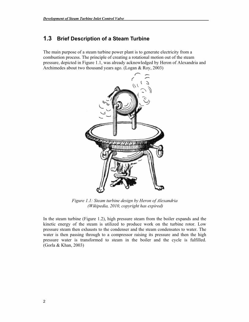
The main purpose of a steam turbine power plant is to generate electricity from a combustion process. The principle of creating a rotational motion out of the steam pressure, depicted in Figure 1.1, was already acknowledged by Heron of Alexandria and Archimedes about two thousand years ago. (Logan & Roy, 2003)
Figure 1.1: Steam turbine design by Heron of Alexandria (Wikipedia, 2010, copyright has expired)
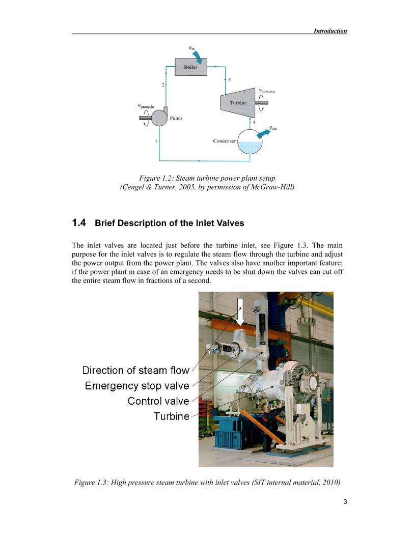
In the steam turbine (Figure 1.2), high pressure steam from the boiler expands and the kinetic energy of the steam is utilized to produce work on the turbine rotor. Low pressure steam then exhausts to the condenser and the steam condensates to water. The water is then passing through to a compressor raising its pressure and then the high pressure water is transformed to steam in the boiler and the cycle is fulfilled. (Gorla & Khan, 2003)
Introduction
3
Figure 1.2: Steam turbine power plant setup (Çengel & Turner, 2005, by permission of McGraw-Hill)
1.4 Brief Description of the Inlet Valves
The inlet valves are located just before the turbine inlet, see Figure 1.3. The main purpose for the inlet valves is to regulate the steam flow through the turbine and adjust the power output from the power plant. The valves also have another important feature; if the power plant in case of an emergency needs to be shut down the valves can cut off the entire steam flow in fractions of a second.
Figure 1.3: High pressure steam turbine with inlet valves (SIT internal material, 2010)
Development of Steam Turbine Inlet Control Valve
4
1.5 Problem Description
The purposes for the inlet valves are to regulate the steam flow and to enable a quick shut off in case of an emergency. They are tightly integrated to the turbine casing in order to guide the steam in an optimal way to the turbine rotor. Today’s valves are dimensioned for much lower performance than the new requirements in terms of temperature and pressure.
The task is to develop new valve concepts for higher steam parameters. This work incorporates concept deployment, stress-strain analysis and solid mechanics analysis, evaluation of seals and development of the dimensioning data.
1.6 Limitations
• The main focus will be at the control valve and only minor attention will be paid to the emergency stop valve.
• The materials for the components of the valves are essential, but the choices and eventual tests will be done by the material experts at Siemens.
• Vibrations should be considered during the concept development but no large-scale research will be done trying to understand how large the vibrations are and how they behave.
• The present servo, used for actuating the valve, will not be examined in detail. Just the dimensioning forces will be estimated.
Introduction
5
1.7 Report Layout
The layout of the report will now be presented in order to help the reader to get a good general view.
• 1 Introduction This chapter consists of a company presentation, a technical briefing and an introduction to the main task.
• 2 Theory In this chapter there is more information about steam turbines, heat power cycles, inlet valves and material theory.
• 3 Method The chapter contains descriptions of the methods used during the phases of product specification, concept generation and concept evaluation.
• 4 Concept Development The description of the concept development process is presented in this chapter.
• 5 Further Development In this chapter the three chosen concepts are further develop in different areas of interest.
• 6 Results This chapter summarizes the results from the previous chapters.
• 7 Discussion This part of the report contains discussions about the chosen methods, the retrieved results and ideas concerning future work.
• 8 Conclusions A summarized version of the results and the major conclusions from these are presented in this chapter.
• 9 Bibliography All referred literature will be presented here as well as website addresses.
• 10 Appendix In this final part of the report there will be some additional information that might be interested for some readers. It contains the project planning, some pictures of the concepts and other material created during the project.

Theory
7
2 Theory
This chapter consists of a more detailed description about steam turbines, steam power cycles, inlet valves and material science.
2.1 Steam Turbines
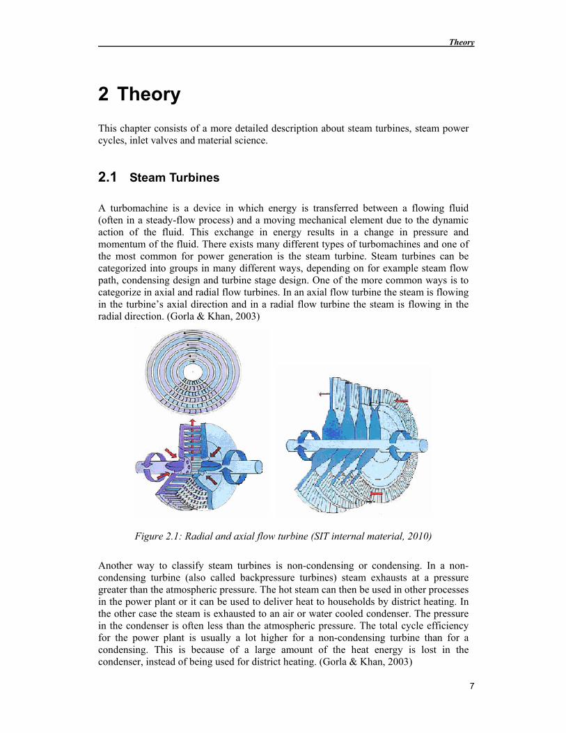
A turbomachine is a device in which energy is transferred between a flowing fluid (often in a steady-flow process) and a moving mechanical element due to the dynamic action of the fluid. This exchange in energy results in a change in pressure and momentum of the fluid. There exists many different types of turbomachines and one of the most common for power generation is the steam turbine. Steam turbines can be categorized into groups in many different ways, depending on for example steam flow path, condensing design and turbine stage design. One of the more common ways is to categorize in axial and radial flow turbines. In an axial flow turbine the steam is flowing in the turbine’s axial direction and in a radial flow turbine the steam is flowing in the radial direction. (Gorla & Khan, 2003)
Figure 2.1: Radial and axial flow turbine (SIT internal material, 2010)
Another way to classify steam turbines is non-condensing or condensing. In a non-condensing turbine (also called backpressure turbines) steam exhausts at a pressure greater than the atmospheric pressure. The hot steam can then be used in other processes in the power plant or it can be used to deliver heat to households by district heating. In the other case the steam is exhausted to an air or water cooled condenser. The pressure in the condenser is often less than the atmospheric pressure. The total cycle efficiency for the power plant is usually a lot higher for a non-condensing turbine than for a condensing. This is because of a large amount of the heat energy is lost in the condenser, instead of being used for district heating. (Gorla & Khan, 2003)
Development of Steam Turbine Inlet Control Valve
8
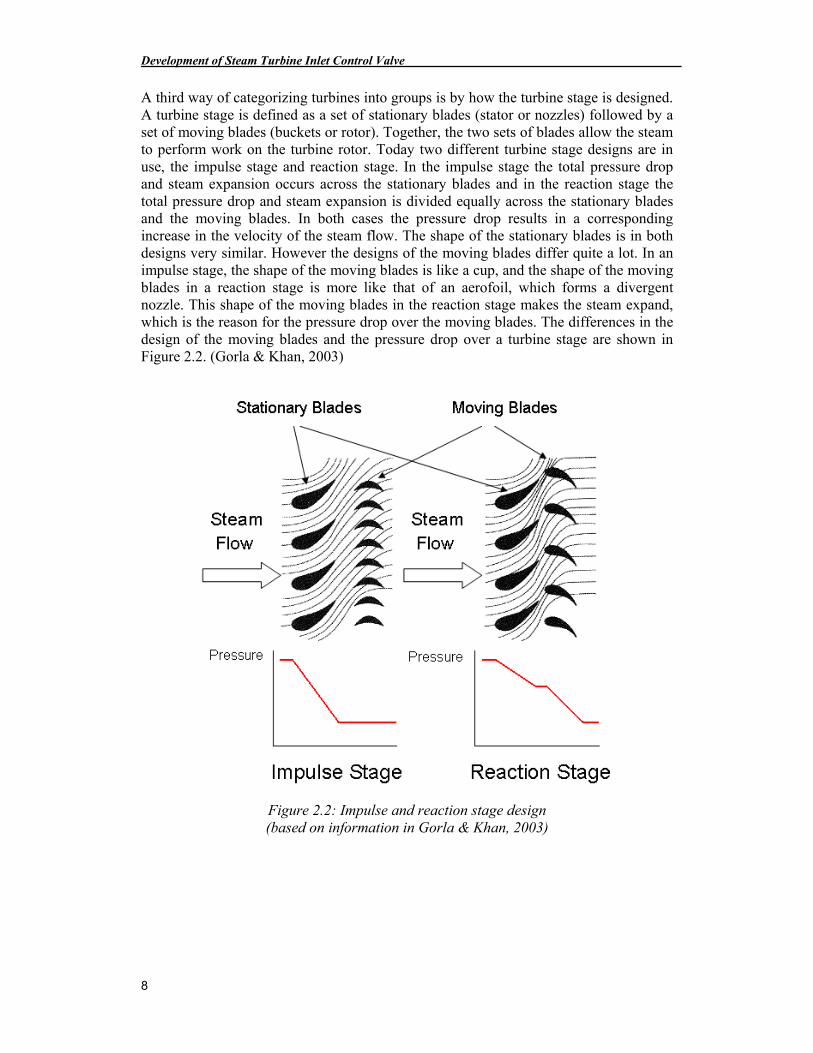
A third way of categorizing turbines into groups is by how the turbine stage is designed. A turbine stage is defined as a set of stationary blades (stator or nozzles) followed by a set of moving blades (buckets or rotor). Together, the two sets of blades allow the steam to perform work on the turbine rotor. Today two different turbine stage designs are in use, the impulse stage and reaction stage. In the impulse stage the total pressure drop and steam expansion occurs across the stationary blades and in the reaction stage the total pressure drop and steam expansion is divided equally across the stationary blades and the moving blades. In both cases the pressure drop results in a corresponding increase in the velocity of the steam flow. The shape of the stationary blades is in both designs very similar. However the designs of the moving blades differ quite a lot. In an impulse stage, the shape of the moving blades is like a cup, and the shape of the moving blades in a reaction stage is more like that of an aerofoil, which forms a divergent nozzle. This shape of the moving blades in the reaction stage makes the steam expand, which is the reason for the pressure drop over the moving blades. The differences in the design of the moving blades and the pressure drop over a turbine stage are shown in Figure 2.2. (Gorla & Khan, 2003)
Figure 2.2: Impulse and reaction stage design (based on information in Gorla & Khan, 2003)
Theory
9
Today the most common stage design for steam turbines is impulse stage. However, in practice there must be some pressure drop across the rotating blades in order to generate flow. Even if the turbine stage design is a “pure” impulse design, it will have some pressure drops across the rotating blades. (Logan & Roy, 2003)
2.1.1 Isentropic Efficiency of Turbines
For a steam turbine under steady operation, the inlet state of the working fluid and the exhaust pressure are fixed. The ideal process for an adiabatic (no heat exchange) turbine is an isentropic process between the inlet state and the exhaust pressure. An isentropic process is one in which the entropy of the inlet and exhaust state is the same. However, in reality there are no truly isentropic processes. The isentropic efficiency of a turbine is defined as the ratio of the actual work produced by the turbine to the work output that would be achieved if the process between the inlet state and the exhaust state were isentropic. (Çengel & Turner, 2005)
The isentropic efficiency is a measurement on the performance of only the steam turbine and does not include losses in other parts of the system (boiler, condenser and pump). The efficiency of the entire power plant can be estimated by the thermal efficiency of the Rankine power cycle, see chapter 2.2.3. The isentropic efficiency is typically around 70-90% and the thermal efficiency for the entire power plant is around 30-50%, which is strongly dependent on the steam parameters for the power plant.
2.2 Steam Power Cycles
This chapter contains information about property diagrams and heat power cycles and might be interesting for some readers but is not necessary for the development process of the inlet valves. The heat power cycles are used to describe how the temperature and the pressure of the steam changes during the energy/heat exchange process in the steam power plant. This theory is then used to explain and motivate why an increase in temperature and pressure increases the efficiency of the power plant.
Development of Steam Turbine Inlet Control Valve
10
2.2.1 Property Diagram
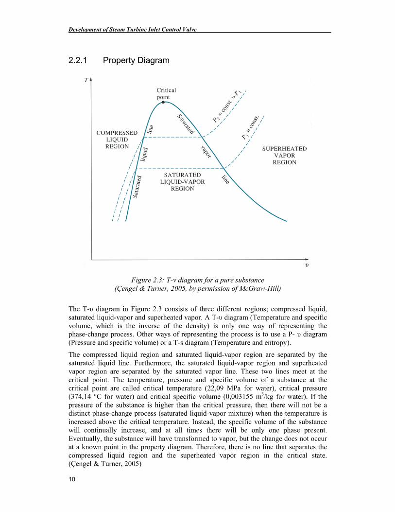
Figure 2.3: T-v diagram for a pure substance (Çengel & Turner, 2005, by permission of McGraw-Hill)
The T-υ diagram in Figure 2.3 consists of three different regions; compressed liquid, saturated liquid-vapor and superheated vapor. A T-υ diagram (Temperature and specific volume, which is the inverse of the density) is only one way of representing the phase-change process. Other ways of representing the process is to use a P- υ diagram (Pressure and specific volume) or a T-s diagram (Temperature and entropy).
The compressed liquid region and saturated liquid-vapor region are separated by the saturated liquid line. Furthermore, the saturated liquid-vapor region and superheated vapor region are separated by the saturated vapor line. These two lines meet at the critical point. The temperature, pressure and specific volume of a substance at the critical point are called critical temperature (22,09 MPa for water), critical pressure (374,14 °C for water) and critical specific volume (0,003155 m3/kg for water). If the pressure of the substance is higher than the critical pressure, then there will not be a distinct phase-change process (saturated liquid-vapor mixture) when the temperature is increased above the critical temperature. Instead, the specific volume of the substance will continually increase, and at all times there will be only one phase present. Eventually, the substance will have transformed to vapor, but the change does not occur at a known point in the property diagram. Therefore, there is no line that separates the compressed liquid region and the superheated vapor region in the critical state. (Çengel & Turner, 2005)
Theory
11
2.2.2 The Carnot Cycle
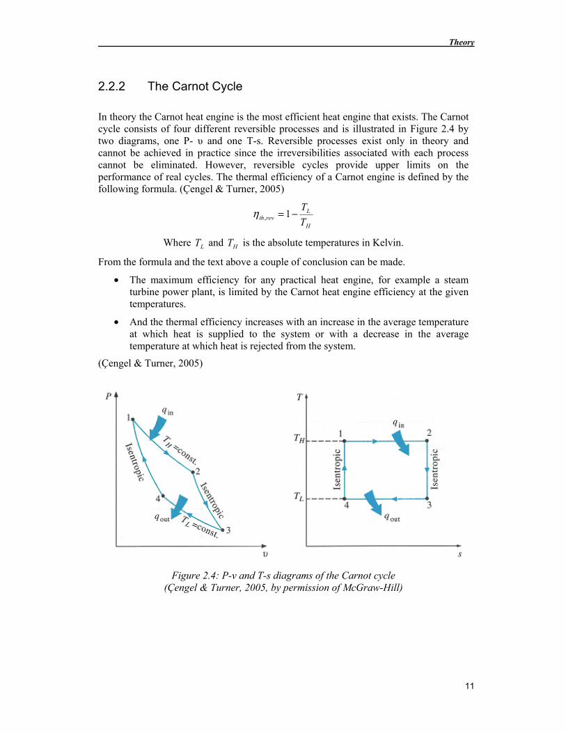
In theory the Carnot heat engine is the most efficient heat engine that exists. The Carnot cycle consists of four different reversible processes and is illustrated in Figure 2.4 by two diagrams, one P- υ and one T-s. Reversible processes exist only in theory and cannot be achieved in practice since the irreversibilities associated with each process cannot be eliminated. However, reversible cycles provide upper limits on the performance of real cycles. The thermal efficiency of a Carnot engine is defined by the following formula. (Çengel & Turner, 2005)
H
Lrevth T
T−= 1,η
Where LT and HT is the absolute temperatures in Kelvin.
From the formula and the text above a couple of conclusion can be made.
• The maximum efficiency for any practical heat engine, for example a steam turbine power plant, is limited by the Carnot heat engine efficiency at the given temperatures.
• And the thermal efficiency increases with an increase in the average temperature at which heat is supplied to the system or with a decrease in the average temperature at which heat is rejected from the system.
(Çengel & Turner, 2005)
Figure 2.4: P-v and T-s diagrams of the Carnot cycle (Çengel & Turner, 2005, by permission of McGraw-Hill)
Development of Steam Turbine Inlet Control Valve
12
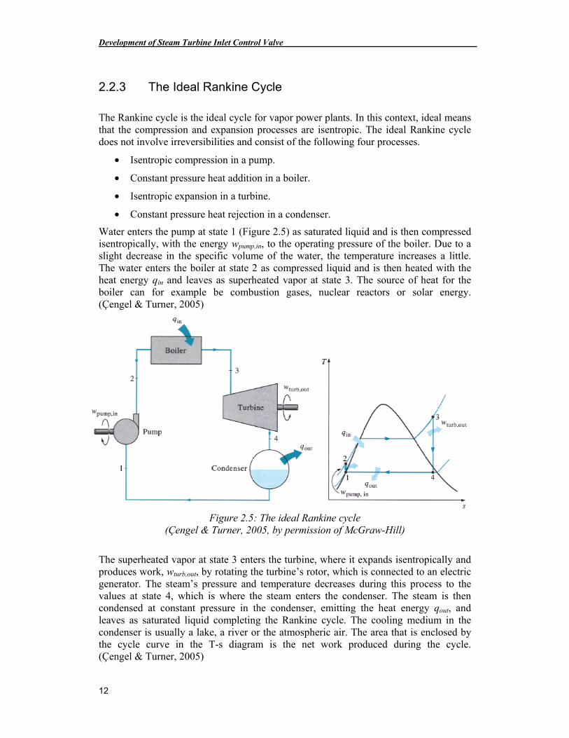
2.2.3 The Ideal Rankine Cycle
The Rankine cycle is the ideal cycle for vapor power plants. In this context, ideal means that the compression and expansion processes are isentropic. The ideal Rankine cycle does not involve irreversibilities and consist of the following four processes.
• Isentropic compression in a pump.
• Constant pressure heat addition in a boiler.
• Isentropic expansion in a turbine.
• Constant pressure heat rejection in a condenser.
Water enters the pump at state 1 (Figure 2.5) as saturated liquid and is then compressed isentropically, with the energy wpump,in, to the operating pressure of the boiler. Due to a slight decrease in the specific volume of the water, the temperature increases a little. The water enters the boiler at state 2 as compressed liquid and is then heated with the heat energy qin and leaves as superheated vapor at state 3. The source of heat for the boiler can for example be combustion gases, nuclear reactors or solar energy. (Çengel & Turner, 2005)
Figure 2.5: The ideal Rankine cycle (Çengel & Turner, 2005, by permission of McGraw-Hill)
The superheated vapor at state 3 enters the turbine, where it expands isentropically and produces work, wturb,out, by rotating the turbine’s rotor, which is connected to an electric generator. The steam’s pressure and temperature decreases during this process to the values at state 4, which is where the steam enters the condenser. The steam is then condensed at constant pressure in the condenser, emitting the heat energy qout, and leaves as saturated liquid completing the Rankine cycle. The cooling medium in the condenser is usually a lake, a river or the atmospheric air. The area that is enclosed by the cycle curve in the T-s diagram is the net work produced during the cycle. (Çengel & Turner, 2005)
Theory
13
The thermal efficiency of the Rankine power cycle is defined as follows.
in
out
in
outin
in
netth q
q
q
q
w−=
−== 1η
The thermal efficiency can also be seen graphically in the T-s diagram (Figure 2.5) for the cycle. The net work, wnet, produced by the cycle is, as mention earlier, the area that is enclosed by the cycle curve. And the thermal energy, qin, added to the cycle is the area that is between the curve (state 2 to state 3, Figure 2.5) and the s-axis in the T-s diagram. (Çengel & Turner, 2005)
2.2.4 Increasing the Efficiency when using the Rankine Cycle
Steam power plants are essential for a big part of the world’s energy production and even small increases in thermal efficiency can mean large savings from the fuel requirements and reducing the power plants carbon-footprint (the total set of greenhouse gases emissions caused by an organization). (Çengel & Turner, 2005)
The basic idea behind how to improve the thermal efficiency of any power cycle is the same; increase the average temperature at which heat is transferred to the working fluid in the boiler, or decrease the average temperature at which heat is rejected from the working fluid in the condenser. For the Rankine cycle it basically exists three different ways of increasing the efficiency, and they are as follows.
• Lowering the condenser pressure.
• Superheating the steam to higher temperatures.
• Increasing the boiler pressure.
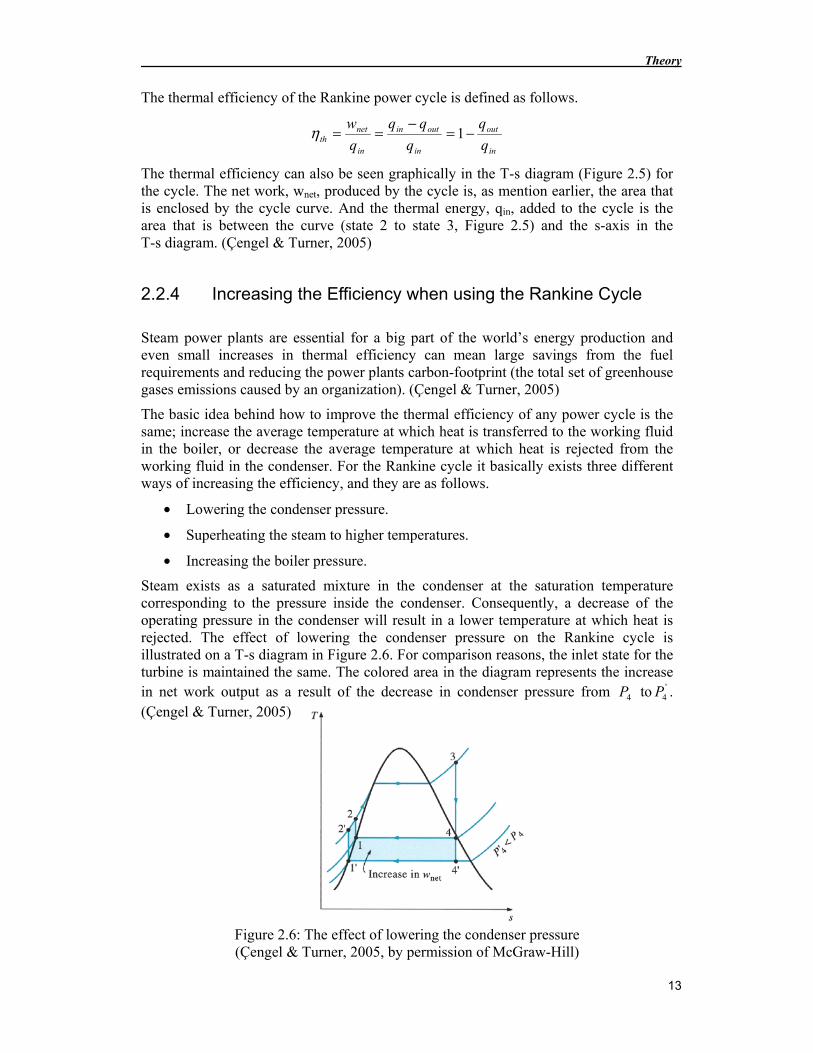
Steam exists as a saturated mixture in the condenser at the saturation temperature corresponding to the pressure inside the condenser. Consequently, a decrease of the operating pressure in the condenser will result in a lower temperature at which heat is rejected. The effect of lowering the condenser pressure on the Rankine cycle is illustrated on a T-s diagram in Figure 2.6. For comparison reasons, the inlet state for the turbine is maintained the same. The colored area in the diagram represents the increase in net work output as a result of the decrease in condenser pressure from 4P to '
4P . (Çengel & Turner, 2005)
Figure 2.6: The effect of lowering the condenser pressure (Çengel & Turner, 2005, by permission of McGraw-Hill)
Development of Steam Turbine Inlet Control Valve
14
The required heat input also increase, which is represented by the area under curve 2’-2 (Figure 2.6). However the increase in net work output is much bigger in comparison to the heat input increase and as a result the efficiency of the Rankine cycle increases. (Çengel & Turner, 2005)
However, there is a lower limit on the condenser pressure that can be used. The pressure is limited by the properties of the cooling medium, more precisely the steams saturation pressure corresponding to the temperature of the cooling medium. Consider the following example; the condenser is being cooled by a nearby river or lake at 15 °C, to sustain a effective heat transfer the difference should be at least 10 °C, then the steam temperature must be above 25 °C and the corresponding saturation pressure at that temperature is 3,2 kPa. Consequently, if the condenser pressure is below 3,2 kPa at 25 °C the steam will not condense. (Çengel & Turner, 2005)
However, the decrease in condenser pressure has a drawback; it increases the moisture content of the steam at the final stages of the turbine, which can be seen in Figure 2.6. Large quantities of moisture are undesirable in turbines because it decreases the turbine efficiency and erodes the turbine blades. (Çengel & Turner, 2005)
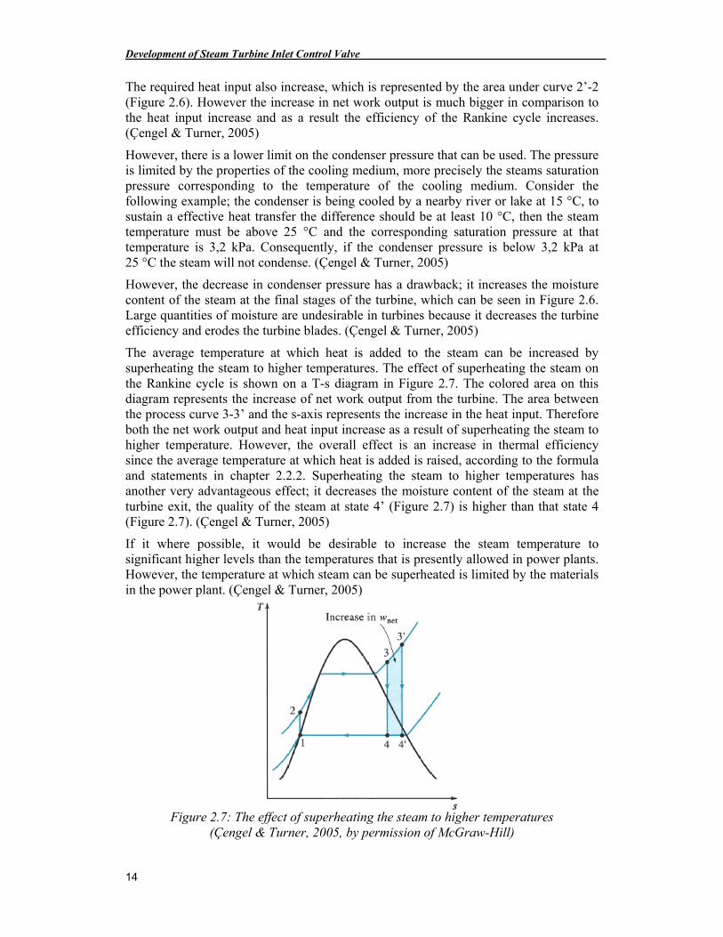
The average temperature at which heat is added to the steam can be increased by superheating the steam to higher temperatures. The effect of superheating the steam on the Rankine cycle is shown on a T-s diagram in Figure 2.7. The colored area on this diagram represents the increase of net work output from the turbine. The area between the process curve 3-3’ and the s-axis represents the increase in the heat input. Therefore both the net work output and heat input increase as a result of superheating the steam to higher temperature. However, the overall effect is an increase in thermal efficiency since the average temperature at which heat is added is raised, according to the formula and statements in chapter 2.2.2. Superheating the steam to higher temperatures has another very advantageous effect; it decreases the moisture content of the steam at the turbine exit, the quality of the steam at state 4’ (Figure 2.7) is higher than that state 4 (Figure 2.7). (Çengel & Turner, 2005)
If it where possible, it would be desirable to increase the steam temperature to significant higher levels than the temperatures that is presently allowed in power plants. However, the temperature at which steam can be superheated is limited by the materials in the power plant. (Çengel & Turner, 2005)
Figure 2.7: The effect of superheating the steam to higher temperatures (Çengel & Turner, 2005, by permission of McGraw-Hill)
Theory
15
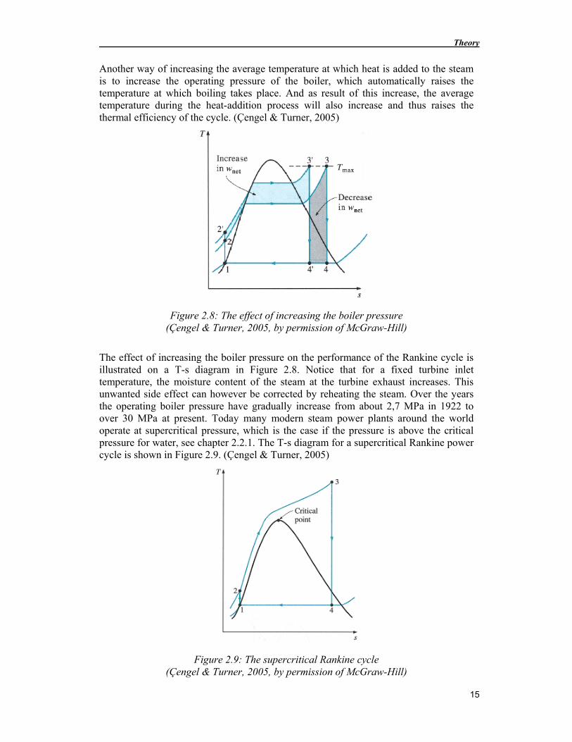
Another way of increasing the average temperature at which heat is added to the steam is to increase the operating pressure of the boiler, which automatically raises the temperature at which boiling takes place. And as result of this increase, the average temperature during the heat-addition process will also increase and thus raises the thermal efficiency of the cycle. (Çengel & Turner, 2005)
Figure 2.8: The effect of increasing the boiler pressure (Çengel & Turner, 2005, by permission of McGraw-Hill)
The effect of increasing the boiler pressure on the performance of the Rankine cycle is illustrated on a T-s diagram in Figure 2.8. Notice that for a fixed turbine inlet temperature, the moisture content of the steam at the turbine exhaust increases. This unwanted side effect can however be corrected by reheating the steam. Over the years the operating boiler pressure have gradually increase from about 2,7 MPa in 1922 to over 30 MPa at present. Today many modern steam power plants around the world operate at supercritical pressure, which is the case if the pressure is above the critical pressure for water, see chapter 2.2.1. The T-s diagram for a supercritical Rankine power cycle is shown in Figure 2.9. (Çengel & Turner, 2005)
Figure 2.9: The supercritical Rankine cycle (Çengel & Turner, 2005, by permission of McGraw-Hill)
Development of Steam Turbine Inlet Control Valve
16
2.2.5 The Ideal Reheat Rankine Cycle
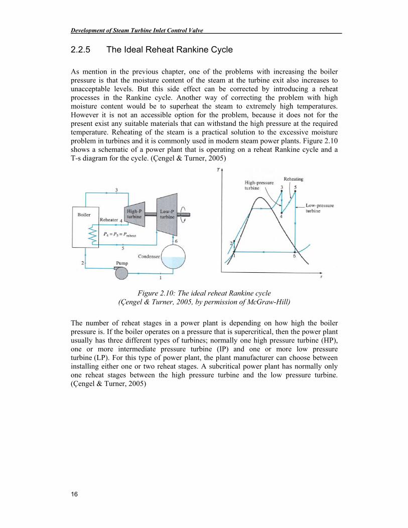
As mention in the previous chapter, one of the problems with increasing the boiler pressure is that the moisture content of the steam at the turbine exit also increases to unacceptable levels. But this side effect can be corrected by introducing a reheat processes in the Rankine cycle. Another way of correcting the problem with high moisture content would be to superheat the steam to extremely high temperatures. However it is not an accessible option for the problem, because it does not for the present exist any suitable materials that can withstand the high pressure at the required temperature. Reheating of the steam is a practical solution to the excessive moisture problem in turbines and it is commonly used in modern steam power plants. Figure 2.10 shows a schematic of a power plant that is operating on a reheat Rankine cycle and a T-s diagram for the cycle. (Çengel & Turner, 2005)
Figure 2.10: The ideal reheat Rankine cycle (Çengel & Turner, 2005, by permission of McGraw-Hill)
The number of reheat stages in a power plant is depending on how high the boiler pressure is. If the boiler operates on a pressure that is supercritical, then the power plant usually has three different types of turbines; normally one high pressure turbine (HP), one or more intermediate pressure turbine (IP) and one or more low pressure turbine (LP). For this type of power plant, the plant manufacturer can choose between installing either one or two reheat stages. A subcritical power plant has normally only one reheat stages between the high pressure turbine and the low pressure turbine. (Çengel & Turner, 2005)
Theory
17
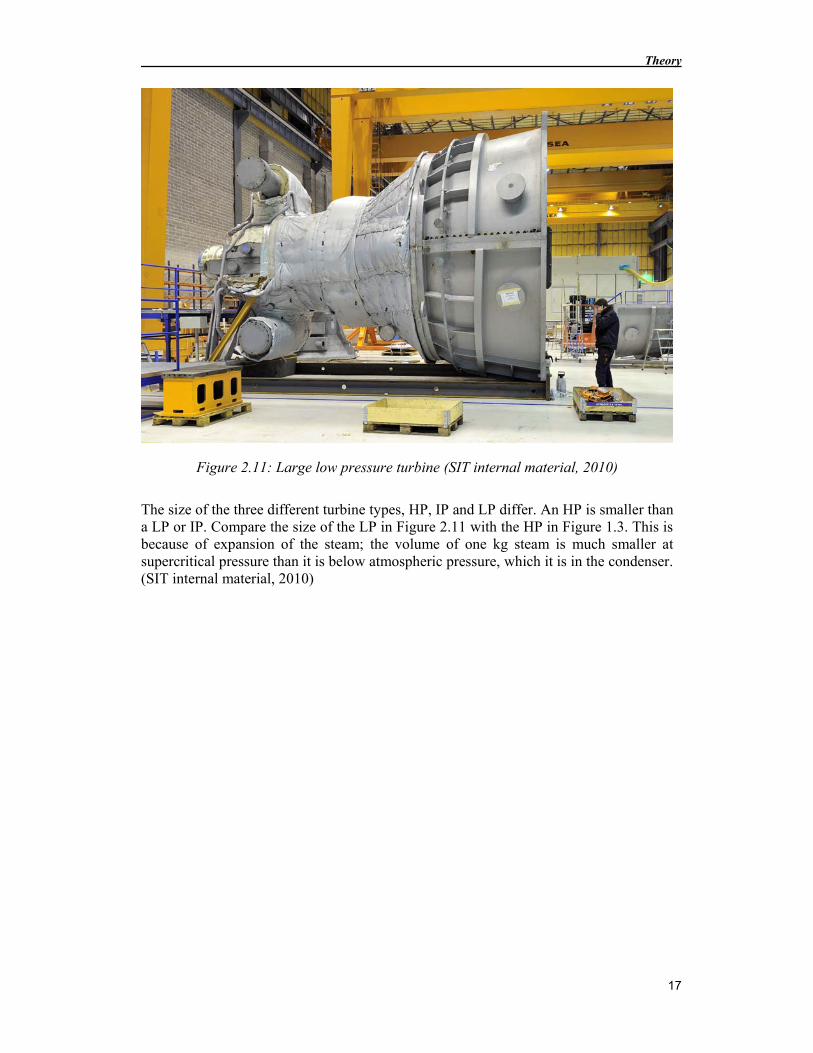
Figure 2.11: Large low pressure turbine (SIT internal material, 2010)
The size of the three different turbine types, HP, IP and LP differ. An HP is smaller than a LP or IP. Compare the size of the LP in Figure 2.11 with the HP in Figure 1.3. This is because of expansion of the steam; the volume of one kg steam is much smaller at supercritical pressure than it is below atmospheric pressure, which it is in the condenser. (SIT internal material, 2010)
Development of Steam Turbine Inlet Control Valve
18
2.3 Inlet Valves
The inlet valves have two important tasks. The first and most obvious purpose with the valves is to adjust the steam flow. The second purpose is to enable steam cut off in case of an emergency.
2.3.1 Safety Requirements
In order to obtain required safety two valves must be mounted in series, as seen in Figure 1.3. The first is an ESV (Emergency Stop Valve) with the only purpose to be able to cut off the steam flow in case of an emergency. The ESV is usually fully open and therefore designed for minimum pressure loss. The second valve is a CV (Control Valve) used for regulating the steam flow and also this one is able to cut off the steam flow quickly. Both emergency stop devices are so called fail-safe which means that they will close also without any help from surrounding systems, such as electric and hydraulic systems.
Another safety demand requires that the valve must be designed in such a way that no component, or part of component, can ever fall into the turbine if it comes loose. Even just a small piece can cause tremendous damage to the turbine.
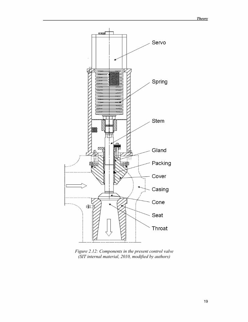
2.3.2 Present Valve Design
The valve used today at Siemens, shown in Figure 2.12, is a poppet valve mounted directly to the turbine inlet. High pressure steam enters the valve from the left and exits downwards into the turbine. The amount of steam flowing through the turbine is depending on how much the cone is raised from the seat and the diameter of the throat. The cone is lifted (making the valve open) with a hydraulic servo that is attached to the cone with the stem. Around the stem there is a graphite packing preventing the steam from leaking out from the valve towards the servo. The graphite packing is compressed by the pressure applied from the gland. Finally there is a strong set of cup springs used for closing the valve for regulating purpose as well as emergency shut off. The cover holds all the components in place within the casing.
Theory
19
Figure 2.12: Components in the present control valve (SIT internal material, 2010, modified by authors)
Development of Steam Turbine Inlet Control Valve
20
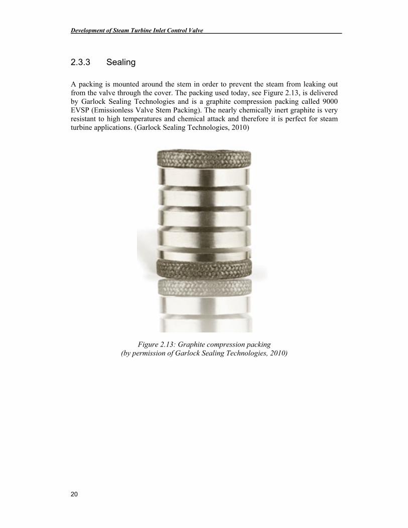
2.3.3 Sealing
A packing is mounted around the stem in order to prevent the steam from leaking out from the valve through the cover. The packing used today, see Figure 2.13, is delivered by Garlock Sealing Technologies and is a graphite compression packing called 9000 EVSP (Emissionless Valve Stem Packing). The nearly chemically inert graphite is very resistant to high temperatures and chemical attack and therefore it is perfect for steam turbine applications. (Garlock Sealing Technologies, 2010)
Figure 2.13: Graphite compression packing (by permission of Garlock Sealing Technologies, 2010)
Theory
21
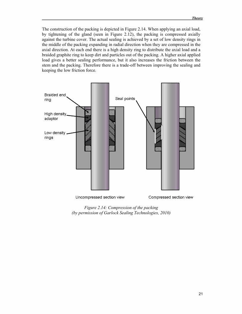
The construction of the packing is depicted in Figure 2.14. When applying an axial load, by tightening of the gland (seen in Figure 2.12), the packing is compressed axially against the turbine cover. The actual sealing is achieved by a set of low density rings in the middle of the packing expanding in radial direction when they are compressed in the axial direction. At each end there is a high density ring to distribute the axial load and a braided graphite ring to keep dirt and particles out of the packing. A higher axial applied load gives a better sealing performance, but it also increases the friction between the stem and the packing. Therefore there is a trade-off between improving the sealing and keeping the low friction force.
Figure 2.14: Compression of the packing (by permission of Garlock Sealing Technologies, 2010)
Development of Steam Turbine Inlet Control Valve
22
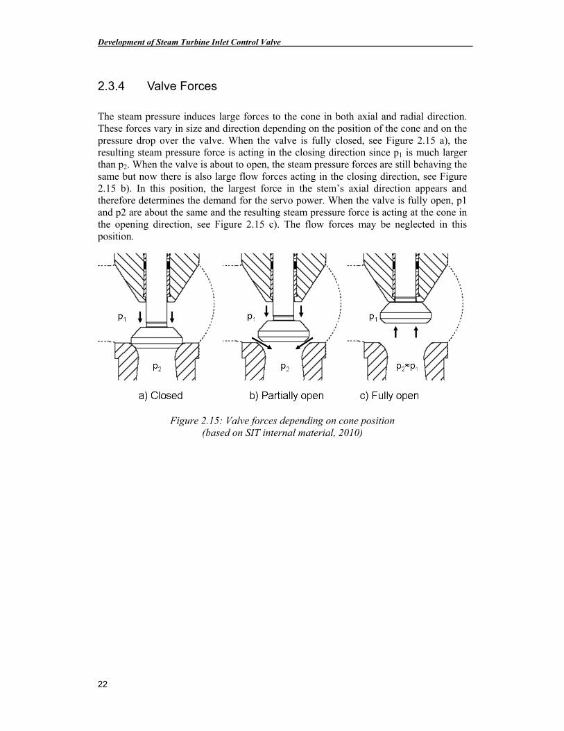
2.3.4 Valve Forces
The steam pressure induces large forces to the cone in both axial and radial direction. These forces vary in size and direction depending on the position of the cone and on the pressure drop over the valve. When the valve is fully closed, see Figure 2.15 a), the resulting steam pressure force is acting in the closing direction since p1 is much larger than p2. When the valve is about to open, the steam pressure forces are still behaving the same but now there is also large flow forces acting in the closing direction, see Figure 2.15 b). In this position, the largest force in the stem’s axial direction appears and therefore determines the demand for the servo power. When the valve is fully open, p1 and p2 are about the same and the resulting steam pressure force is acting at the cone in the opening direction, see Figure 2.15 c). The flow forces may be neglected in this position.
Figure 2.15: Valve forces depending on cone position (based on SIT internal material, 2010)
Theory
23
2.3.5 Limitations with the Present Design
Today’s valve design is optimized for the current steam conditions and would not stand the forces and wearing due to changed steam parameters without tremendous changes in dimensions and materials. These are the reasons:
• Today’s cup springs, if assumed that the rest of the valve would withstand the stress, would need to have a spring coefficient slightly more than twice as high because of the required increase in spring forces as a result of increased pressure and packing friction forces.
• Servo power needs to be increased due to higher pressure and larger friction forces in the packing, which is induced by the higher preload required making it seal properly.
• Spring forces are most critical since SIT AB are already using the strongest standard component cup springs close to their maximum performance. Increasing the servo power, on the other hand, is easy and just requires a larger cylinder and piston areas.
• The packing wearing does also increase, due to vibrations, according to acquired knowledge and studies of the present design.
• Stem stresses and strains are increased with the raised pressure. This is problematic in combination with the decreasing creep strength of the material due to the raised temperature. The stem diameter may easily be enlarged but this requires enlarging of the spring force and the packing leading to an overall enlargement of the valve casing.
• Cone deflection problems in the opening moment lead to changed cone geometry (higher cone) and therefore slightly larger casing.
• The larger the casing gets the thicker the castings must be, leading to a tremendous increase of material and this is affecting the cost of the valve severely.
These described limitations explain why it is desirable to consider changes in the design of the control valve.
Development of Steam Turbine Inlet Control Valve
24
0
100
200
500 550 600 650
Temperature °C
Cre
ep s
tren
gth
(10
0 00
0 h
) in
MP
a
"X20" steel (11% to 12% Cr)Introduction: 1960
COST 501 materials up to 610 °C.Introduction: 1994
COST 522 materials up to 630 °C.Introduction: 2005
COST 536 materials up to 650 °C.Introduction: after 2010
2.4 Material
This is a stand-alone chapter which contains information that might be interesting for some readers but is not necessary for the understanding of the development process.
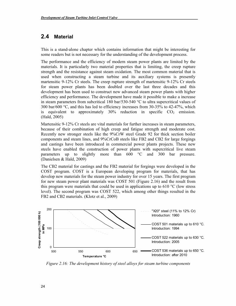
The performance and the efficiency of modern steam power plants are limited by the materials. It is particularly two material properties that is limiting, the creep rupture strength and the resistance against steam oxidation. The most common material that is used when constructing a steam turbine and its auxiliary systems is presently martensitic 9-12% Cr steels. The creep rupture strength of martensitic 9-12% Cr steels for steam power plants has been doubled over the last three decades and this development has been used to construct new advanced steam power plants with higher efficiency and performance. The development have made it possible to make a increase in steam parameters from subcritical 180 bar/530-540 °C to ultra supercritical values of 300 bar/600 °C, and this has led to efficiency increases from 30-35% to 42-47%, which is equivalent to approximately 30% reduction in specific CO2 emission. (Hald, 2005)
Martensitic 9-12% Cr steels are vital materials for further increases in steam parameters, because of their combination of high creep and fatigue strength and moderate cost. Recently new stronger steels like the 9%CrW steel Grade 92 for thick section boiler components and steam lines, and 9%CrCoB steels like FB2 and CB2 for large forgings and castings have been introduced in commercial power plants projects. These new steels have enabled the construction of power plants with supercritical live steam parameters up to slightly more than 600 °C and 300 bar pressure. (Danielsen & Hald, 2009)
The CB2 material for castings and the FB2 material for forgings were developed in the COST program. COST is a European developing program for materials, that has develop new materials for the steam power industry for over 15 years. The first program for new steam power plant materials was COST 501 (Figure 2.16) and the result from this program were materials that could be used in applications up to 610 °C (low stress level). The second program was COST 522, which among other things resulted in the FB2 and CB2 materials. (Klotz et al., 2009)
Figure 2.16: The development history of steel alloys for steam turbine components
Theory
25
Materials from the COST 522 program have higher creep strength and improved oxidation resistance in comparison with materials that is use in commercial power plants today. Under the past 2-3 years new materials has been developed in the new COST 536 program with the aim of developing Cr steel materials that can be used in temperatures up to 650 °C without fracture. Materials from the COST 536 program will hopefully be introduced on the market in a couple of years, which will enable a further increase in the efficiency of the steam power plants. (Klotz et al., 2009)
2.4.1 Material Complexity with Cr Steels
One of the challenges that are associated with the development of new materials is the time aspect, before new creep resistant steel can be introduced on the market it has to withstand extensive long-term testing. This means that the lead time for a new alloy from laboratory to power plant approaches 10 years. (Hald, 2005)
In order to further increase the steam parameters of steel-based power plants up to a target value of 650 °C and 325 bar, it is necessary to double the creep strength compared with Grade 92, and at the same time improve the resistance against steam oxidation. If the oxidation protection is to be achieved through alloy additions instead of surface coatings, then it is necessary to increase the Chromium content in the steels from 9% to 12%. However, so far all such attempts to make stronger 12% Cr steels have failed because the high chromium content introduced severe microstructure instabilities in the tested steels, which led to breakdown in long-term creep strength. (Danielsen & Hald, 2009)
The long-term creep strength of the new generations of martensitic steels relies strongly on particle strengthening by fine MN nitrides based on V and Nb. However recent research has demonstrated that the MN nitrides may be replaced by the thermodynamically more stable Z-phases, Cr(V,Nb)N, which precipitate as coarse particles and dissolve the fine nitrides. This phase transformation has been found to be a main cause for observed long-term microstructure instabilities in the new martensitic steels. Thus, the Z-phase transformation is a main cause for the lack of success to develop strong martensitic steels with 12% Cr for improved oxidation resistance. (Danielsen & Hald, 2009)
Understanding of the nucleation and growth of the Z-phase precipitation is one of the keys to understand the differences in creep strength of Cr steels. During the last ten years a number of different material tests at high temperatures, in the region of 650 °C, and calculation based on driving force models for the Z-phase, has shown that the content of Cr is a very significant element of the precipitation of Z-phase. The conclusion from the tests and calculation is that a Cr content above 10,5% strongly accelerate precipitation of Z-phase and dissolution of the fine MN nitrides, which reduces the creep strength of the steel. Tests have shown that steels with only 9% Cr have a low observed quantity of Z-phase in the material even after a very long time at high temperatures. (Danielsen & Hald, 2009)
Development of Steam Turbine Inlet Control Valve
26
2.4.2 Coating of the Material
As mentioned, the goal for material developing programs is to develop a steel material that withstands the creep and steam oxidation at the target values for the steam parameters 650 °C and 325 bar. Further developments of 9% Cr steels with low C or optimized B and N contents seem to be able to increase the long-term creep strength close to the target level of 100 MPa for rupture after 100 000 h at 650 °C. However, it is not only the creep strength that has to be improved if the target values for the steam parameters should be realized. As mentioned earlier, the oxidation resistance must also be improved. So if optimized 9% Cr steels should be used at service temperatures significantly higher than 600 °C it is necessary to apply a surface coating to the material. (Danielsen & Hald, 2009)
The most promising coating materials are different aluminum alloys. Aluminide coatings have been shown to drastically reduce the oxidation rate in steam environment. There is however one main problem with the conventional aluminizing process and that is the high aluminizing temperatures. Conventional aluminizing processes are carried out at 900 – 1150 °C, and heat treatment of martensitic steels at these temperatures can severely decrease their mechanical properties, which will make it impossible to satisfy the target level of rupture creep strength. The solution to this problem is to carry out the aluminizing process at a lower temperature. The development of low - temperature aluminizing processes have shown some promising progress under the past couple of years. But there are still researches to be done before all aspects of low – temperature aluminide coatings are covered. (Zhang et al., 2008)
Even if it’s possible to solve the problem with coatings, it might not be a good solution to the problem with oxidation resistance for materials in steam power plants. The introduction of coatings on the materials will probably induce a whole set of new problems, that could lead to component failure and risks for unexpected plant outages. The coating must withstand at least 100 000 h at the operation conditions, which will include wear and fatigue at high temperatures among other things. And the production cost will definitely increase. (Danielsen & Hald, 2009)
Theory
27
2.4.3 Future Material for Steam Turbines
Because of the problems that are associated with developing Cr steels for operation conditions at 650 °C, steam turbine manufactures have under past decade started to develop new steam turbine concepts for even higher steam parameters. Recent develop projects like the European AD700 have focused on a jump in steam temperature up to 700 °C based on the use of very expensive nickel-based alloys for different components in the power plant. nickel–based alloys have better mechanical properties than Cr steel alloys at high temperatures, they are however many times more expansive than Cr steel alloys, and that is why the manufactures do not want to use them if not the performance increases is big enough, which occur at a jump to 700 °C. (Danielsen & Hald, 2009)
However, the developed understanding and modeling of the earlier mentioned Z-phase might create new opportunities for alloy development of high Cr martensitic steels, which follows philosophy: If you can not beat them, join them. The big problem with the Z-phase is that it precipitates as coarse particles instead of fine. However, if it where possible to provoke the Z-phase itself to precipitate very quickly in fine distribution, which would provide particle strengthening, then the steel could be expected to be resistant against dissolution of its strengthening particles even at very high temperatures. (Danielsen & Hald, 2009)
Calculations based on driving force model for Z-phase have shown that one of the most important steps to accelerate Z-phase precipitation is to increase the Cr content to the highest possible level. And all at once, the high Cr content is then turned from being the main cause of instability into being an important element to secure the long-term microstructure stability of the martensitic steels. And at the same time should the high Cr content provide a good steam oxidation protection for the steel. (Danielsen & Hald, 2009)
Ongoing work with the development of Z-phase strengthened steels at the Technical University (TU) of Denmark has shown some very promising experiment result under past couple years. If successful, the research at TU Denmark could result in new martensitic 12% Cr steels strengthened by Z-phase, which could enable the design of ultra supercritical power plants with steam parameters up to the target value of 650 °C and 325 bar, without using any very expansive nickel-based alloys. (Danielsen & Hald, 2009)

Method
29
3 Method
Product development is a comprehensive process with many sub-processes which have a more or less good theoretical basis. Although a lot has been written, a fundamental generally accepted method for product development does not yet exist. (Johannesson et al., 2004)
Systematic methods for product development have been used for many years without being described and published. The first books in the subject were written during the 1970s and today there are a lot of books available. Most of the authors are dividing the product development process into the following steps, even though they use different notations for these steps.
• Product specification
• Concept generation
• Concept evaluation and concept decision
• Technical design
• Manufacturing adaption
(Johannesson et al., 2004)
For each of the items in the list there are a great number of very different methods to choose from. What method you pick depends on the task, the available time and personal preferences. The rest of this chapter contains descriptions of those methods that were found appropriate for this project. Just minor attention will be paid to the technical design and no work will be done in the manufacturing adoption since this project is just at the conceptual state.
3.1 Product Specification
In the product specification the aim is to get familiar with the assignment and to gather additional information that is missing in the description of the task. Then a specification concerning what should be done need to be established. This one should be formulated in such a way that it can be used in order to find suitable design solutions and as a reference when evaluating the design concepts. (Johannesson et al., 2004)
3.1.1 Quality Function Deployment
In order to generate engineering specifications there are many techniques used. One of the currently most popular is called Quality Function Deployment (QFD). It is organized to develop the major pieces of information necessary to understand the problem. (Ullman, 2003)
Development of Steam Turbine Inlet Control Valve
30
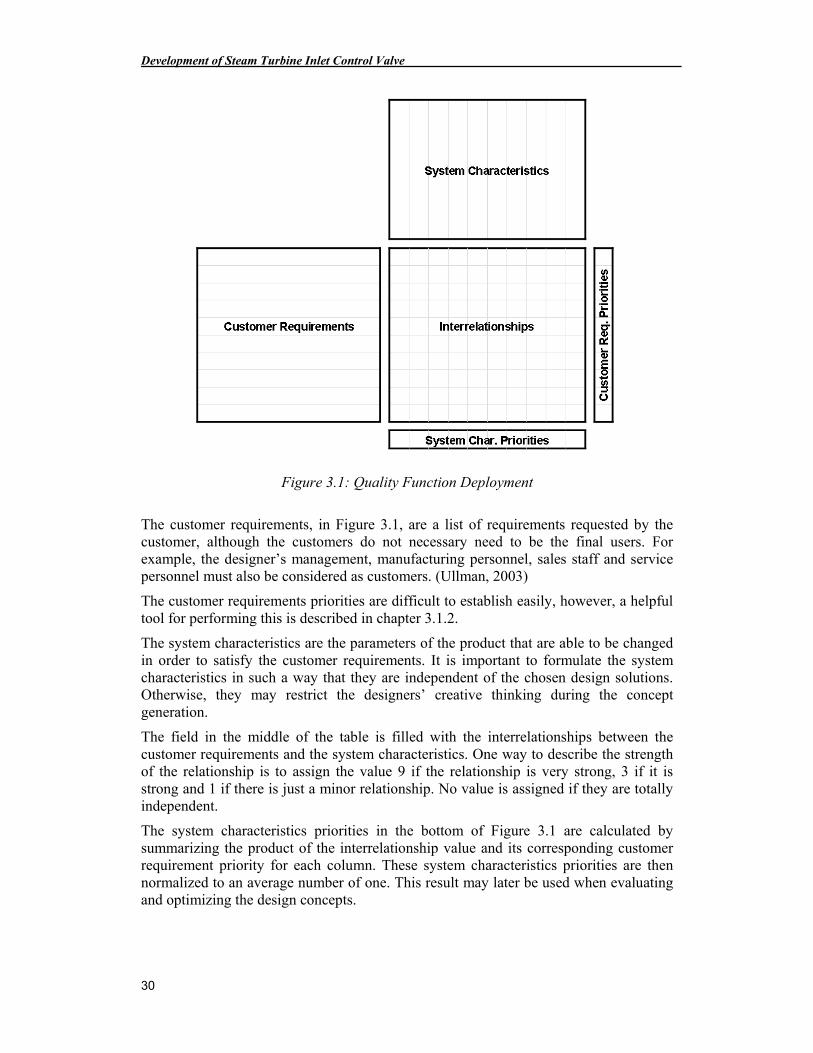
Figure 3.1: Quality Function Deployment
The customer requirements, in Figure 3.1, are a list of requirements requested by the customer, although the customers do not necessary need to be the final users. For example, the designer’s management, manufacturing personnel, sales staff and service personnel must also be considered as customers. (Ullman, 2003)
The customer requirements priorities are difficult to establish easily, however, a helpful tool for performing this is described in chapter 3.1.2.
The system characteristics are the parameters of the product that are able to be changed in order to satisfy the customer requirements. It is important to formulate the system characteristics in such a way that they are independent of the chosen design solutions. Otherwise, they may restrict the designers’ creative thinking during the concept generation.
The field in the middle of the table is filled with the interrelationships between the customer requirements and the system characteristics. One way to describe the strength of the relationship is to assign the value 9 if the relationship is very strong, 3 if it is strong and 1 if there is just a minor relationship. No value is assigned if they are totally independent.
The system characteristics priorities in the bottom of Figure 3.1 are calculated by summarizing the product of the interrelationship value and its corresponding customer requirement priority for each column. These system characteristics priorities are then normalized to an average number of one. This result may later be used when evaluating and optimizing the design concepts.
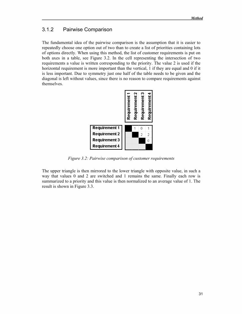
Method
31
3.1.2 Pairwise Comparison
The fundamental idea of the pairwise comparison is the assumption that it is easier to repeatedly choose one option out of two than to create a list of priorities containing lots of options directly. When using this method, the list of customer requirements is put on both axes in a table, see Figure 3.2. In the cell representing the intersection of two requirements a value is written corresponding to the priority. The value 2 is used if the horizontal requirement is more important than the vertical, 1 if they are equal and 0 if it is less important. Due to symmetry just one half of the table needs to be given and the diagonal is left without values, since there is no reason to compare requirements against themselves.
Figure 3.2: Pairwise comparison of customer requirements
The upper triangle is then mirrored to the lower triangle with opposite value, in such a way that values 0 and 2 are switched and 1 remains the same. Finally each row is summarized to a priority and this value is then normalized to an average value of 1. The result is shown in Figure 3.3.
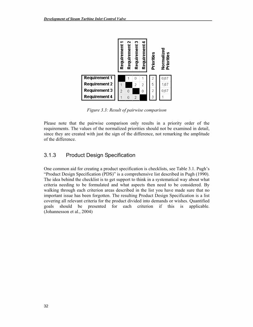
Development of Steam Turbine Inlet Control Valve
32
Figure 3.3: Result of pairwise comparison
Please note that the pairwise comparison only results in a priority order of the requirements. The values of the normalized priorities should not be examined in detail, since they are created with just the sign of the difference, not remarking the amplitude of the difference.
3.1.3 Product Design Specification
One common aid for creating a product specification is checklists, see Table 3.1. Pugh’s “Product Design Specification (PDS)” is a comprehensive list described in Pugh (1990). The idea behind the checklist is to get support to think in a systematical way about what criteria needing to be formulated and what aspects then need to be considered. By walking through each criterion areas described in the list you have made sure that no important issue has been forgotten. The resulting Product Design Specification is a list covering all relevant criteria for the product divided into demands or wishes. Quantified goals should be presented for each criterion if this is applicable. (Johannesson et al., 2004)
Method
33
Table 3.1: Checklist for Product Design Specification
Product lifecycle Stakeholders Aspects Involved
Manufacturing The company Performance
Assembly Customers Environment
Distribution Suppliers Maintenance
Installation Transport companies Aesthetics
Operation Wholesale and retail trade Appearance
Maintenance Customer organizations Materials
Use Legislator Packing
Reuse … …
Disposal
3.2 Concept Generation
The result of the concept generation phase is a number of conceptual design solutions fulfilling the product specification. This is performed in a process where the creative work is supported by methods and systematical procedures. The basic idea is to generate as many alternative solutions as possible to get a good amount of options to choose from. In this way it is likely to find a great majority of the good possible solutions. (Johannesson et al., 2004)
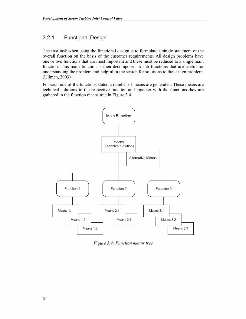
Development of Steam Turbine Inlet Control Valve
34
3.2.1 Functional Design
The first task when using the functional design is to formulate a single statement of the overall function on the basis of the customer requirements. All design problems have one or two functions that are most important and these must be reduced to a single main function. This main function is then decomposed in sub functions that are useful for understanding the problem and helpful in the search for solutions to the design problem. (Ullman, 2003)
For each one of the functions stated a number of means are generated. These means are technical solutions to the respective function and together with the functions they are gathered in the function means tree in Figure 3.4.
Figure 3.4: Function means tree
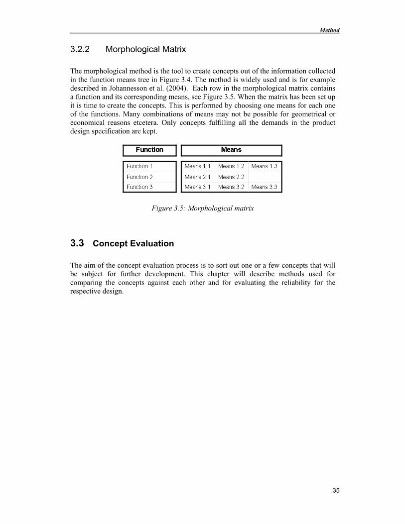
Method
35
3.2.2 Morphological Matrix
The morphological method is the tool to create concepts out of the information collected in the function means tree in Figure 3.4. The method is widely used and is for example described in Johannesson et al. (2004). Each row in the morphological matrix contains a function and its corresponding means, see Figure 3.5. When the matrix has been set up it is time to create the concepts. This is performed by choosing one means for each one of the functions. Many combinations of means may not be possible for geometrical or economical reasons etcetera. Only concepts fulfilling all the demands in the product design specification are kept.
Figure 3.5: Morphological matrix
3.3 Concept Evaluation
The aim of the concept evaluation process is to sort out one or a few concepts that will be subject for further development. This chapter will describe methods used for comparing the concepts against each other and for evaluating the reliability for the respective design.
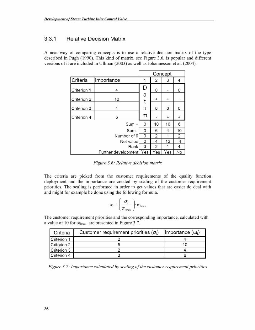
Development of Steam Turbine Inlet Control Valve
36
3.3.1 Relative Decision Matrix
A neat way of comparing concepts is to use a relative decision matrix of the type described in Pugh (1990). This kind of matrix, see Figure 3.6, is popular and different versions of it are included in Ullman (2003) as well as Johannesson et al. (2004).
Figure 3.6: Relative decision matrix
The criteria are picked from the customer requirements of the quality function deployment and the importance are created by scaling of the customer requirement priorities. The scaling is performed in order to get values that are easier do deal with and might for example be done using the following formula.
maxmax
ii
ii ww ⋅
=
σσ
The customer requirement priorities and the corresponding importance, calculated with a value of 10 for ωimax, are presented in Figure 3.7.
Figure 3.7: Importance calculated by scaling of the customer requirement priorities
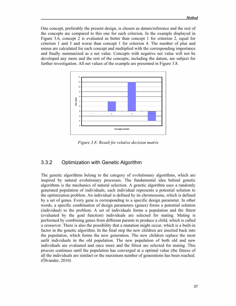
Method
37
One concept, preferably the present design, is chosen as datum/reference and the rest of the concepts are compared to this one for each criterion. In the example displayed in Figure 3.6, concept 2 is evaluated as better than concept 1 for criterion 2, equal for criterion 1 and 3 and worse than concept 1 for criterion 4. The number of plus and minus are calculated for each concept and multiplied with the corresponding importance and finally summarized as a net value. Concepts with negative net value will not be developed any more and the rest of the concepts, including the datum, are subject for further investigation. All net values of the example are presented in Figure 3.8.
Figure 3.8: Result for relative decision matrix
3.3.2 Optimization with Genetic Algorithm
The genetic algorithms belong to the category of evolutionary algorithms, which are inspired by natural evolutionary processes. The fundamental idea behind genetic algorithms is the mechanics of natural selection. A genetic algorithm uses a randomly generated population of individuals, each individual represents a potential solution to the optimization problem. An individual is defined by its chromosome, which is defined by a set of genes. Every gene is corresponding to a specific design parameter. In other words, a specific combination of design parameters (genes) forms a potential solution (individual) to the problem. A set of individuals forms a population and the fittest (evaluated by the goal function) individuals are selected for mating. Mating is performed by combining genes from different parents to produce a child, which is called a crossover. There is also the possibility that a mutation might occur, which is a built-in factor in the genetic algorithm. In the final step the new children are inserted back into the population, which forms the new generation. The new children replace the most unfit individuals in the old population. The new population of both old and new individuals are evaluated and once more and the fittest are selected for mating. This process continues until the population has converged at a optimal value (the fitness of all the individuals are similar) or the maximum number of generations has been reached. (Ölvander, 2010)
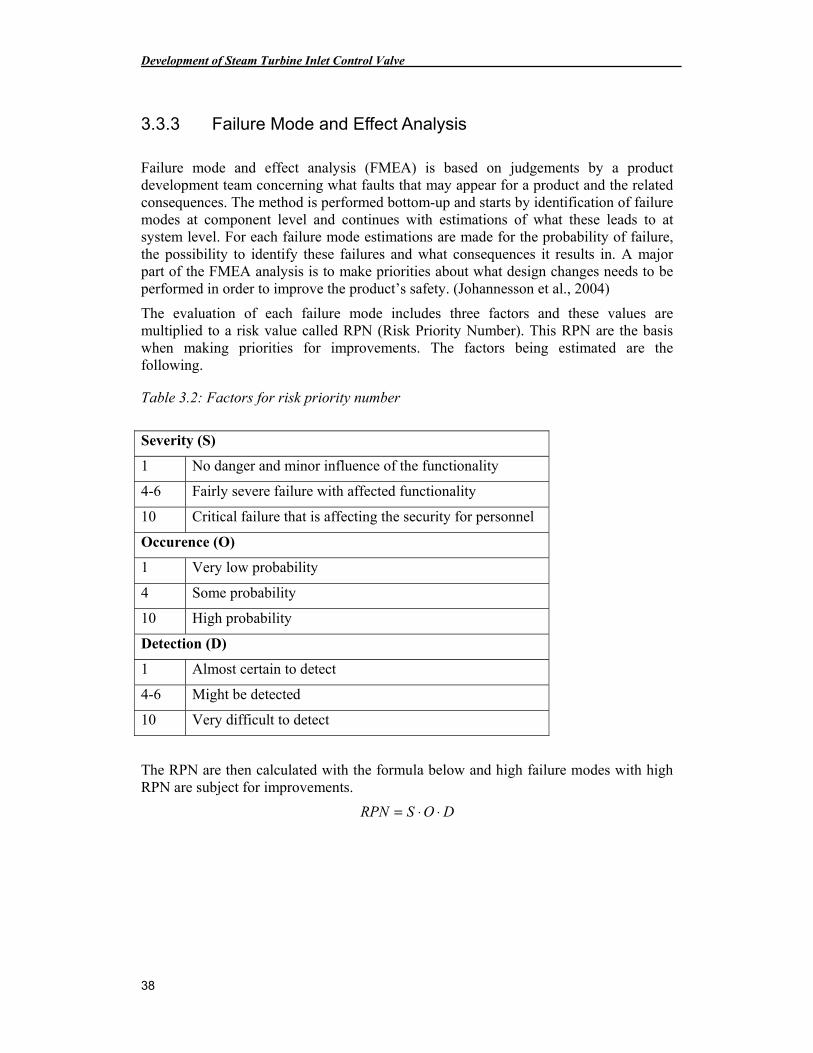
Development of Steam Turbine Inlet Control Valve
38
3.3.3 Failure Mode and Effect Analysis
Failure mode and effect analysis (FMEA) is based on judgements by a product development team concerning what faults that may appear for a product and the related consequences. The method is performed bottom-up and starts by identification of failure modes at component level and continues with estimations of what these leads to at system level. For each failure mode estimations are made for the probability of failure, the possibility to identify these failures and what consequences it results in. A major part of the FMEA analysis is to make priorities about what design changes needs to be performed in order to improve the product’s safety. (Johannesson et al., 2004)
The evaluation of each failure mode includes three factors and these values are multiplied to a risk value called RPN (Risk Priority Number). This RPN are the basis when making priorities for improvements. The factors being estimated are the following.
Table 3.2: Factors for risk priority number
Severity (S)
1 No danger and minor influence of the functionality
4-6 Fairly severe failure with affected functionality
10 Critical failure that is affecting the security for personnel
Occurence (O)
1 Very low probability
4 Some probability
10 High probability
Detection (D)
1 Almost certain to detect
4-6 Might be detected
10 Very difficult to detect
The RPN are then calculated with the formula below and high failure modes with high RPN are subject for improvements.
DOSRPN ⋅⋅=
Concept Development
39
4 Concept Development
A project planning using Gantt chart were made early in the project in order to find out a proper sequence for the tasks and to assign sufficient amount of time for each one of them. The planning was continuously adjusted during the project and the final planning is presented in chapter 10.3.
4.1 Project Specification
The Product Design Specification (PDS) was determined at a brainstorming session with all the involved personnel. The meeting resulted in a PDS, see chapter 10.1, and the project limitations stated in chapter 1.6. The PDS were later refined using Pugh’s checklist.
After the PDS was established, more information about the customer requirements and their correlation with the system characteristics were needed. Because of that, a QFD matrix was established. The customer requirements were identified from the PDS and to rank the different customer requirements that were used in the QFD matrix the pairwise comparison method was used. The results from the pairwise comparison and the QFD matrix are presented in figures on the following pages.
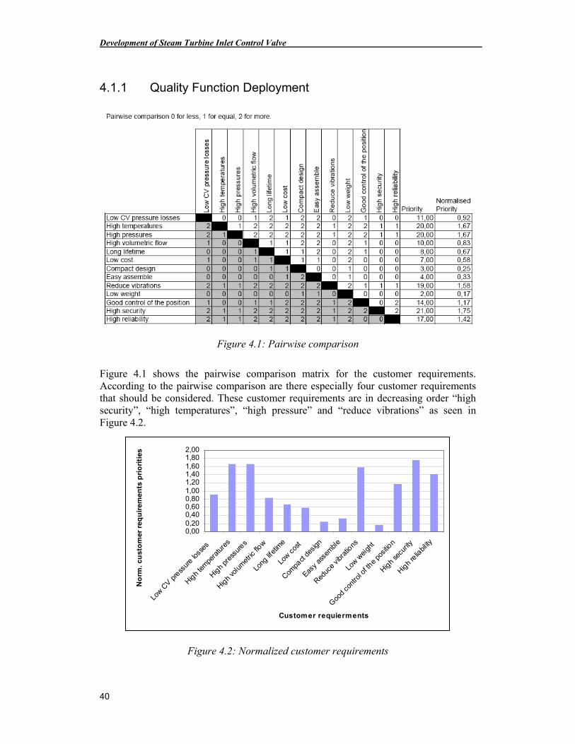
Development of Steam Turbine Inlet Control Valve
40
4.1.1 Quality Function Deployment
Figure 4.1: Pairwise comparison
Figure 4.1 shows the pairwise comparison matrix for the customer requirements. According to the pairwise comparison are there especially four customer requirements that should be considered. These customer requirements are in decreasing order “high security”, “high temperatures”, “high pressure” and “reduce vibrations” as seen in Figure 4.2.
0,000,200,400,600,801,001,201,401,601,802,00
Low C
V pre
ssur
e los
ses
High
tem
pera
ture
s
High
pres
sure
s
High
volu
met
ric flo
w
Long
lifet
ime
Low c
ost
Compa
ct de
sign
Easy
asse
mbl
e
Reduc
e vib
ratio
ns
Low w
eigh
t
Goo
d co
ntro
l of t
he po
sitio
n
High
secu
rity
High
relia
bility
Customer requierments
No
rm. c
ust
om
er r
equ
irem
ents
pri
ori
ties
Figure 4.2: Normalized customer requirements
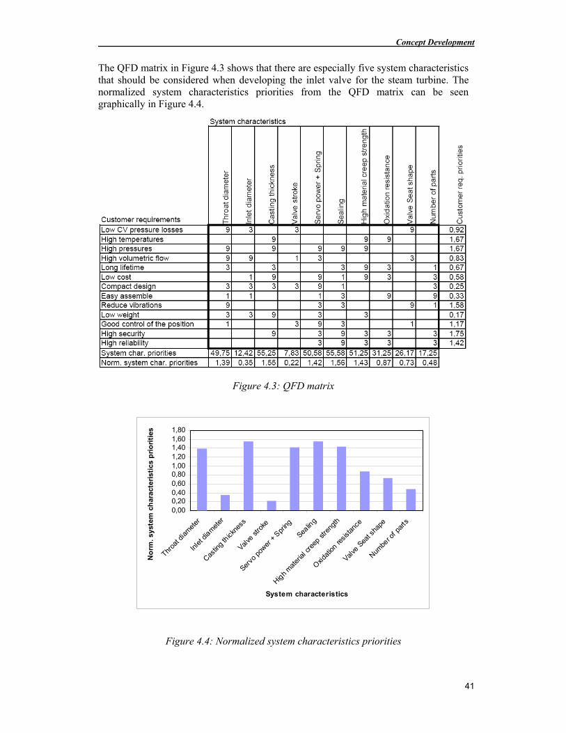
Concept Development
41
The QFD matrix in Figure 4.3 shows that there are especially five system characteristics that should be considered when developing the inlet valve for the steam turbine. The normalized system characteristics priorities from the QFD matrix can be seen graphically in Figure 4.4.
Figure 4.3: QFD matrix
0,000,200,400,600,801,001,201,401,601,80
Throa
t dia
met
er
Inle
t dia
met
er
Castin
g th
ickne
ss
Valve
stro
ke
Servo
pow
er +
Spr
ing
Sealin
g
High
mat
erial
cree
p stre
ngth
Oxid
ation
resis
tanc
e
Valve
Sea
t sha
pe
Numbe
r of p
arts
System characteristics
No
rm. s
yste
m c
har
acte
rist
ics
pri
ori
ties
Figure 4.4: Normalized system characteristics priorities
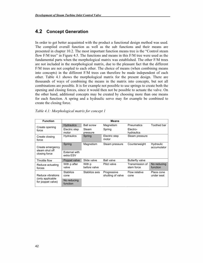
Development of Steam Turbine Inlet Control Valve
42
4.2 Concept Generation
In order to get better acquainted with the product a functional design method was used. The compiled overall function as well as the sub functions and their means are presented in chapter 10.2. The most important function means tree is the “Control steam flow F/M tree” in Figure 4.5. The functions and means in this F/M tree were used as the fundamental parts when the morphological matrix was established. The other F/M trees are not included in the morphological matrix, due to the pleasant fact that the different F/M trees are not coupled to each other. The choice of means (when combining means into concepts) in the different F/M trees can therefore be made independent of each other. Table 4.1 shows the morphological matrix for the present design. There are thousands of ways of combining the means in the matrix into concepts, but not all combinations are possible. It is for example not possible to use springs to create both the opening and closing forces, since it would then not be possible to actuate the valve. On the other hand, additional concepts may be created by choosing more than one means for each function. A spring and a hydraulic servo may for example be combined to create the closing force.
Table 4.1: Morphological matrix for concept 1
Function Means
Hydraulics Ball screw Magnetism Pneumatics Toothed bar Create opening force Electric step
motor Steam pressure
Spring Electro-hydraulics
Create closing force
Hydraulics Spring Electric step motor
Steam pressure
Spring Magnetism Steam pressure Counterweight Hydraulic accumulator Create emergency
steam shut off closing force External with
extra ESV
Throttle flow Poppet valve Slide valve Ball valve Butterfly valve
Reduce actuating forces
With p after valve
With p before valve
Pilot valve Transmission of stem force
No reducing function
Stabilize cone
Stabilize axis Progressive shutting of valve
Flow relative cone
Place cone under seat Reduce vibrations
(only applicable for poppet valve) No reducing
function
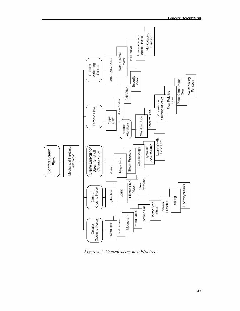
Concept Development
43
Figure 4.5: Control steam flow F/M tree
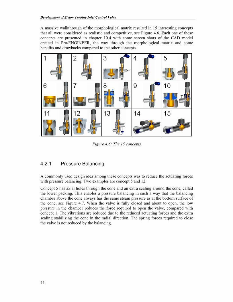
Development of Steam Turbine Inlet Control Valve
44
A massive walkthrough of the morphological matrix resulted in 15 interesting concepts that all were considered as realistic and competitive, see Figure 4.6. Each one of these concepts are presented in chapter 10.4 with some screen shots of the CAD model created in Pro/ENGINEER, the way through the morphological matrix and some benefits and drawbacks compared to the other concepts.
Figure 4.6: The 15 concepts
4.2.1 Pressure Balancing
A commonly used design idea among these concepts was to reduce the actuating forces with pressure balancing. Two examples are concept 5 and 12.
Concept 5 has axial holes through the cone and an extra sealing around the cone, called the lower packing. This enables a pressure balancing in such a way that the balancing chamber above the cone always has the same steam pressure as at the bottom surface of the cone, see Figure 4.7. When the valve is fully closed and about to open, the low pressure in the chamber reduces the force required to open the valve, compared with concept 1. The vibrations are reduced due to the reduced actuating forces and the extra sealing stabilizing the cone in the radial direction. The spring forces required to close the valve is not reduced by the balancing.
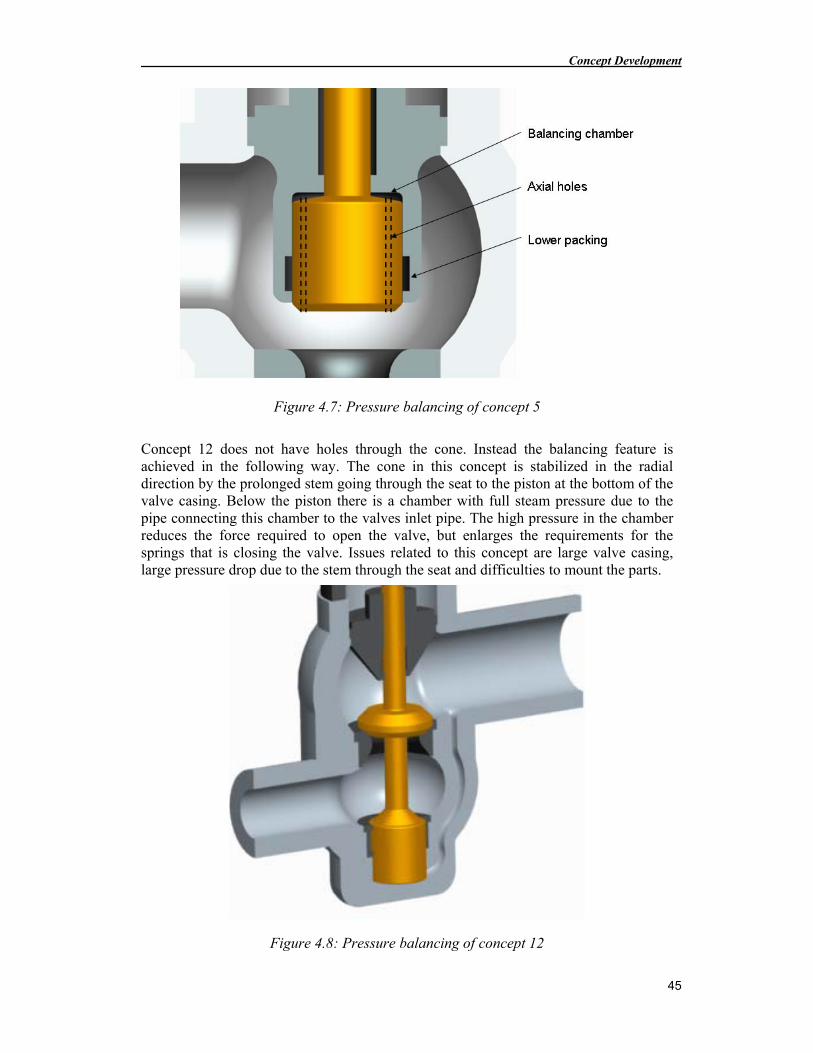
Concept Development
45
Figure 4.7: Pressure balancing of concept 5
Concept 12 does not have holes through the cone. Instead the balancing feature is achieved in the following way. The cone in this concept is stabilized in the radial direction by the prolonged stem going through the seat to the piston at the bottom of the valve casing. Below the piston there is a chamber with full steam pressure due to the pipe connecting this chamber to the valves inlet pipe. The high pressure in the chamber reduces the force required to open the valve, but enlarges the requirements for the springs that is closing the valve. Issues related to this concept are large valve casing, large pressure drop due to the stem through the seat and difficulties to mount the parts.
Figure 4.8: Pressure balancing of concept 12
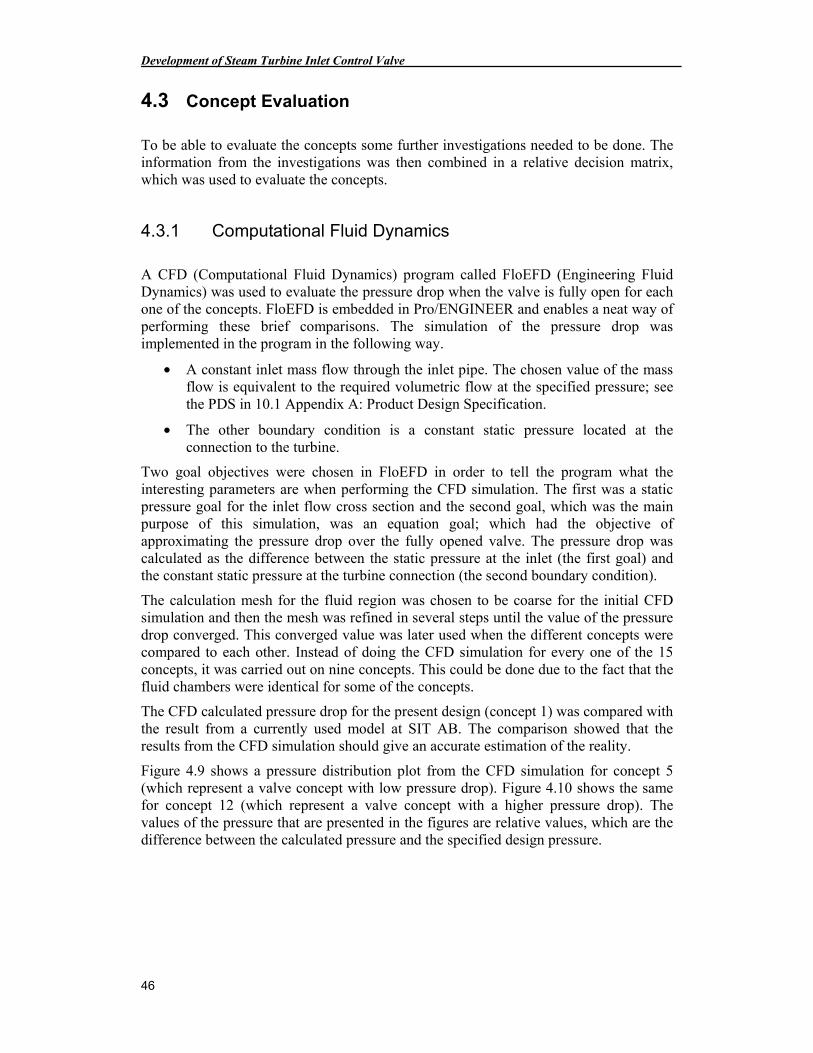
Development of Steam Turbine Inlet Control Valve
46
4.3 Concept Evaluation
To be able to evaluate the concepts some further investigations needed to be done. The information from the investigations was then combined in a relative decision matrix, which was used to evaluate the concepts.
4.3.1 Computational Fluid Dynamics
A CFD (Computational Fluid Dynamics) program called FloEFD (Engineering Fluid Dynamics) was used to evaluate the pressure drop when the valve is fully open for each one of the concepts. FloEFD is embedded in Pro/ENGINEER and enables a neat way of performing these brief comparisons. The simulation of the pressure drop was implemented in the program in the following way.
• A constant inlet mass flow through the inlet pipe. The chosen value of the mass flow is equivalent to the required volumetric flow at the specified pressure; see the PDS in 10.1 Appendix A: Product Design Specification.
• The other boundary condition is a constant static pressure located at the connection to the turbine.
Two goal objectives were chosen in FloEFD in order to tell the program what the interesting parameters are when performing the CFD simulation. The first was a static pressure goal for the inlet flow cross section and the second goal, which was the main purpose of this simulation, was an equation goal; which had the objective of approximating the pressure drop over the fully opened valve. The pressure drop was calculated as the difference between the static pressure at the inlet (the first goal) and the constant static pressure at the turbine connection (the second boundary condition).
The calculation mesh for the fluid region was chosen to be coarse for the initial CFD simulation and then the mesh was refined in several steps until the value of the pressure drop converged. This converged value was later used when the different concepts were compared to each other. Instead of doing the CFD simulation for every one of the 15 concepts, it was carried out on nine concepts. This could be done due to the fact that the fluid chambers were identical for some of the concepts.
The CFD calculated pressure drop for the present design (concept 1) was compared with the result from a currently used model at SIT AB. The comparison showed that the results from the CFD simulation should give an accurate estimation of the reality.
Figure 4.9 shows a pressure distribution plot from the CFD simulation for concept 5 (which represent a valve concept with low pressure drop). Figure 4.10 shows the same for concept 12 (which represent a valve concept with a higher pressure drop). The values of the pressure that are presented in the figures are relative values, which are the difference between the calculated pressure and the specified design pressure.
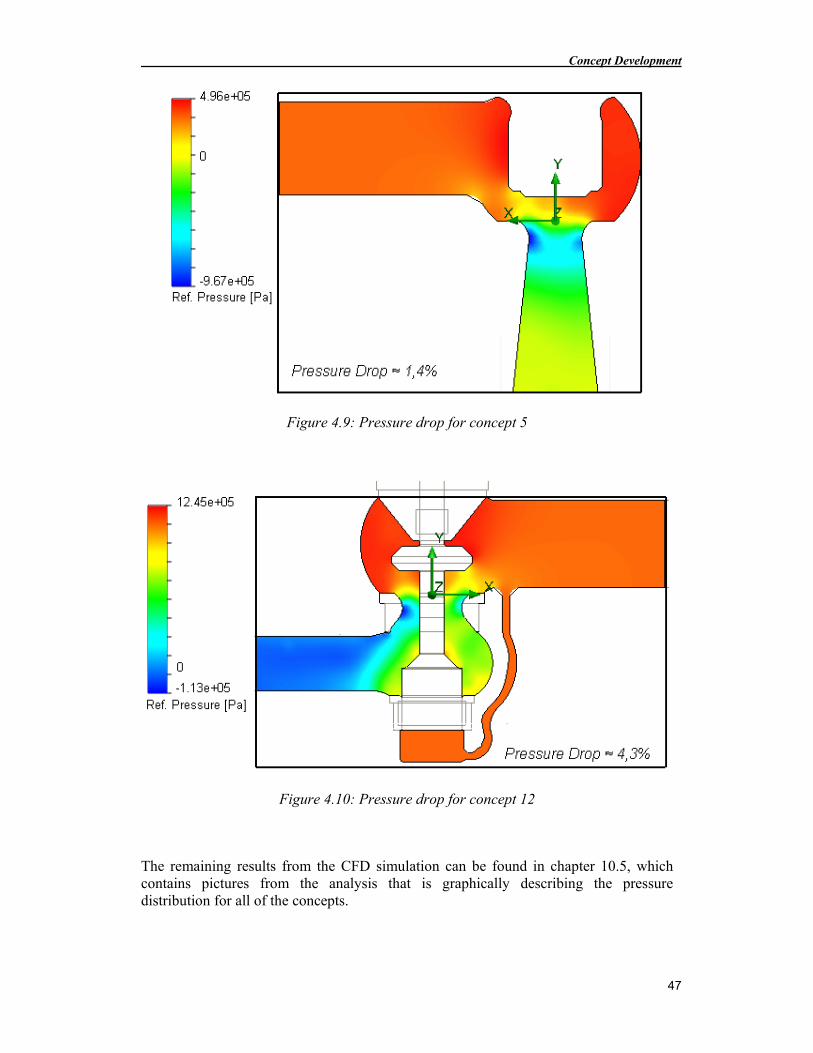
Concept Development
47
Figure 4.9: Pressure drop for concept 5
Figure 4.10: Pressure drop for concept 12
The remaining results from the CFD simulation can be found in chapter 10.5, which contains pictures from the analysis that is graphically describing the pressure distribution for all of the concepts.
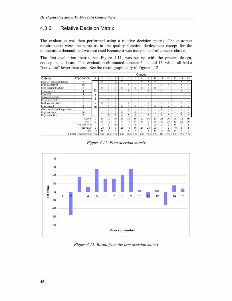
Development of Steam Turbine Inlet Control Valve
48
4.3.2 Relative Decision Matrix
The evaluation was then performed using a relative decision matrix. The customer requirements were the same as in the quality function deployment except for the temperature demand that was not used because it was independent of concept choice.
The first evaluation matrix, see Figure 4.11, was set up with the present design, concept 1, as datum. This evaluation eliminated concept 2, 11 and 13, which all had a “net value” lower than zero. See the result graphically in Figure 4.12.
Figure 4.11: First decision matrix
-40
-30
-20
-10
0
10
20
30
40
1 2 3 4 5 6 7 8 9 10 11 12 13 14 15
Concept number
Net
val
ue
Figure 4.12: Result from the first decision matrix
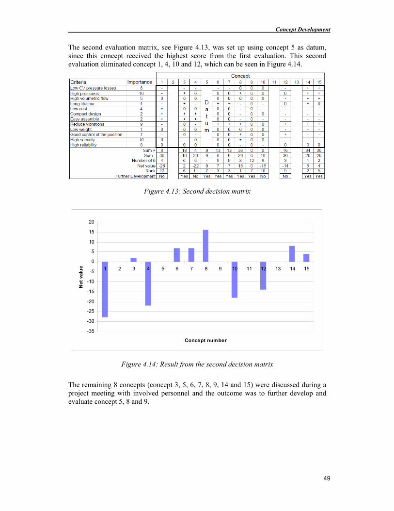
Concept Development
49
The second evaluation matrix, see Figure 4.13, was set up using concept 5 as datum, since this concept received the highest score from the first evaluation. This second evaluation eliminated concept 1, 4, 10 and 12, which can be seen in Figure 4.14.
Figure 4.13: Second decision matrix
-35
-30
-25
-20
-15
-10
-5
0
5
10
15
20
1 2 3 4 5 6 7 8 9 10 11 12 13 14 15
Concept number
Net
val
ue
Figure 4.14: Result from the second decision matrix
The remaining 8 concepts (concept 3, 5, 6, 7, 8, 9, 14 and 15) were discussed during a project meeting with involved personnel and the outcome was to further develop and evaluate concept 5, 8 and 9.

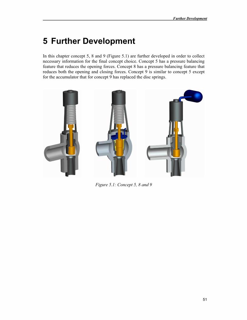
Further Development
51
5 Further Development
In this chapter concept 5, 8 and 9 (Figure 5.1) are further developed in order to collect necessary information for the final concept choice. Concept 5 has a pressure balancing feature that reduces the opening forces. Concept 8 has a pressure balancing feature that reduces both the opening and closing forces. Concept 9 is similar to concept 5 except for the accumulator that for concept 9 has replaced the disc springs.
Figure 5.1: Concept 5, 8 and 9
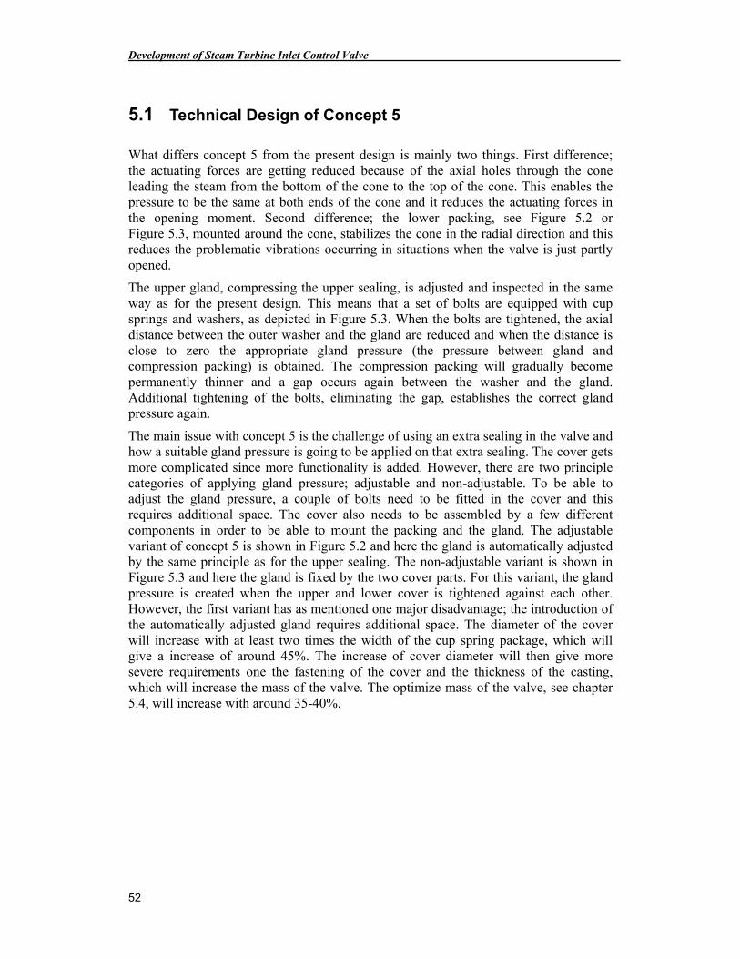
Development of Steam Turbine Inlet Control Valve
52
5.1 Technical Design of Concept 5
What differs concept 5 from the present design is mainly two things. First difference; the actuating forces are getting reduced because of the axial holes through the cone leading the steam from the bottom of the cone to the top of the cone. This enables the pressure to be the same at both ends of the cone and it reduces the actuating forces in the opening moment. Second difference; the lower packing, see Figure 5.2 or Figure 5.3, mounted around the cone, stabilizes the cone in the radial direction and this reduces the problematic vibrations occurring in situations when the valve is just partly opened.
The upper gland, compressing the upper sealing, is adjusted and inspected in the same way as for the present design. This means that a set of bolts are equipped with cup springs and washers, as depicted in Figure 5.3. When the bolts are tightened, the axial distance between the outer washer and the gland are reduced and when the distance is close to zero the appropriate gland pressure (the pressure between gland and compression packing) is obtained. The compression packing will gradually become permanently thinner and a gap occurs again between the washer and the gland. Additional tightening of the bolts, eliminating the gap, establishes the correct gland pressure again.
The main issue with concept 5 is the challenge of using an extra sealing in the valve and how a suitable gland pressure is going to be applied on that extra sealing. The cover gets more complicated since more functionality is added. However, there are two principle categories of applying gland pressure; adjustable and non-adjustable. To be able to adjust the gland pressure, a couple of bolts need to be fitted in the cover and this requires additional space. The cover also needs to be assembled by a few different components in order to be able to mount the packing and the gland. The adjustable variant of concept 5 is shown in Figure 5.2 and here the gland is automatically adjusted by the same principle as for the upper sealing. The non-adjustable variant is shown in Figure 5.3 and here the gland is fixed by the two cover parts. For this variant, the gland pressure is created when the upper and lower cover is tightened against each other. However, the first variant has as mentioned one major disadvantage; the introduction of the automatically adjusted gland requires additional space. The diameter of the cover will increase with at least two times the width of the cup spring package, which will give a increase of around 45%. The increase of cover diameter will then give more severe requirements one the fastening of the cover and the thickness of the casting, which will increase the mass of the valve. The optimize mass of the valve, see chapter 5.4, will increase with around 35-40%.
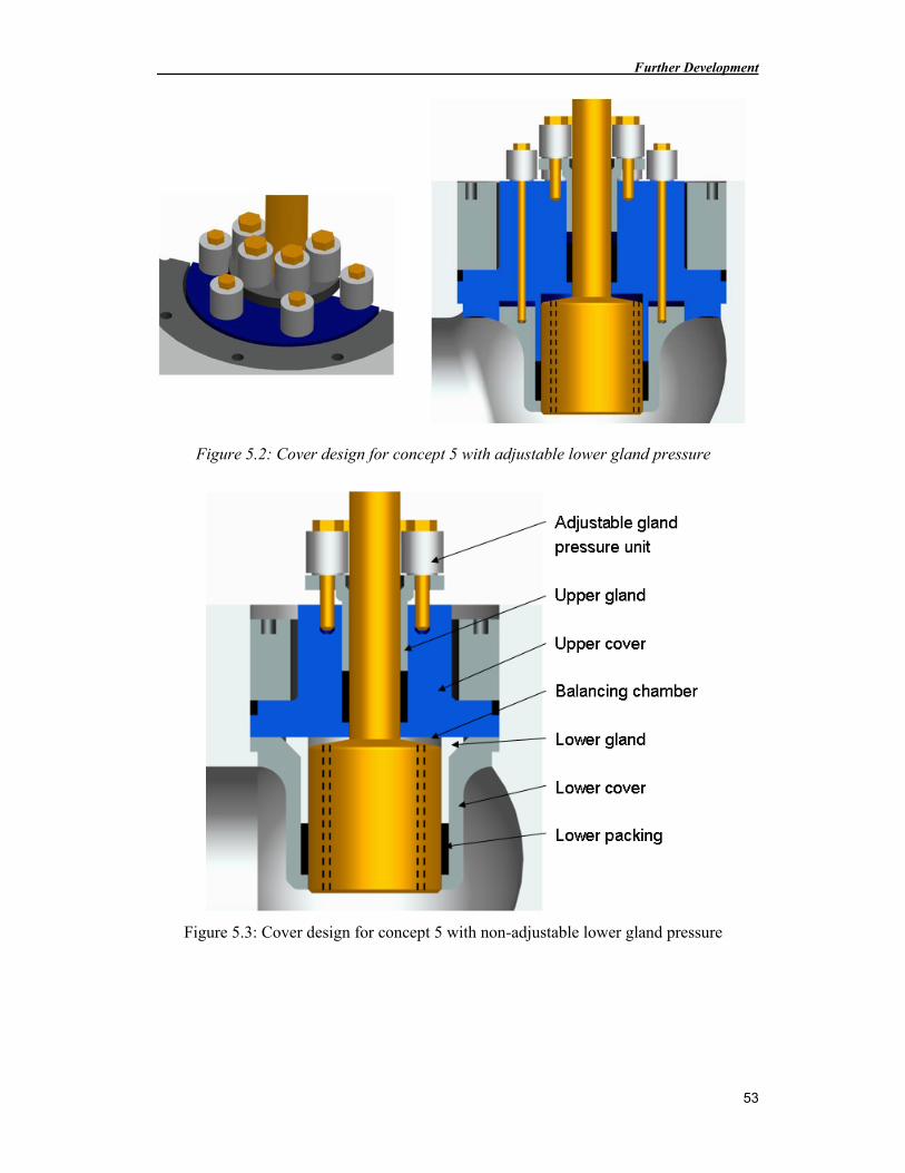
Further Development
53
Figure 5.2: Cover design for concept 5 with adjustable lower gland pressure
Figure 5.3: Cover design for concept 5 with non-adjustable lower gland pressure
Development of Steam Turbine Inlet Control Valve
54
5.1.1 New Cup Springs
The pressure balancing design, with axial holes through the cone, in concept 5 are reducing the actuating forces in the opening moment, which lowers the requirements on the hydraulic force in the servo compared with the present design. However, the forces requirements on the cup springs in the servo unit are not reduced. The new higher steam pressure will increase the requirements on the cup springs. If the present cup springs are to be used, then the spring preload needs to be increased, and this will make the fatigue lifetime to short. And therefore will concept 5 require new cups springs that can withstand higher force requirements.
The German manufacturer Mubea was chosen to be a good candidate for delivering the new cup springs. Mubea produces cup springs in a many dimensions, from small cup springs with an outer diameter on only a few centimeters to large cup springs with an outer diameter on 600 millimeters (Mubea, 2010).
There are especially two aspects that needs to be consider when selecting new cup springs, the force from the springs must be higher than the resulting steam force on the cone at all positions in the valve stroke. And the second aspect is the fatigue lifetime of the cup springs. The spring force at all positions and the fatigue lifetime are both calculated according to the standard DIN 2093. The fatigue lifetime are dependent on the spring preload, the spring stiffness, the valve stroke, the number of cup springs and the material parameters. And the spring force is dependent on the spring preload and the spring stiffness. A higher spring preload provides a higher spring force, but decreases the fatigue lifetime. Figure 5.4 shows a typical spring characteristic for a stack of cup springs.
Figure 5.4: Spring characteristic for a stack of cup springs (based on information from Mubea, 2010)
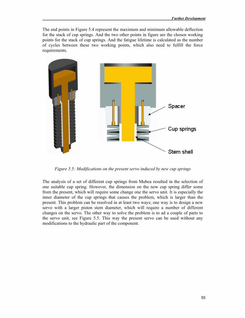
Further Development
55
The end points in Figure 5.4 represent the maximum and minimum allowable deflection for the stack of cup springs. And the two other points in figure are the chosen working points for the stack of cup springs. And the fatigue lifetime is calculated as the number of cycles between these two working points, which also need to fulfill the force requirements.
Figure 5.5: Modifications on the present servo induced by new cup springs
The analysis of a set of different cup springs from Mubea resulted in the selection of one suitable cup spring. However, the dimension on the new cup spring differ some from the present, which will require some change one the servo unit. It is especially the inner diameter of the cup springs that causes the problem, which is larger than the present. This problem can be resolved in at least two ways; one way is to design a new servo with a larger piston stem diameter, which will require a number of different changes on the servo. The other way to solve the problem is to ad a couple of parts to the servo unit, see Figure 5.5. This way the present servo can be used without any modifications to the hydraulic part of the component.
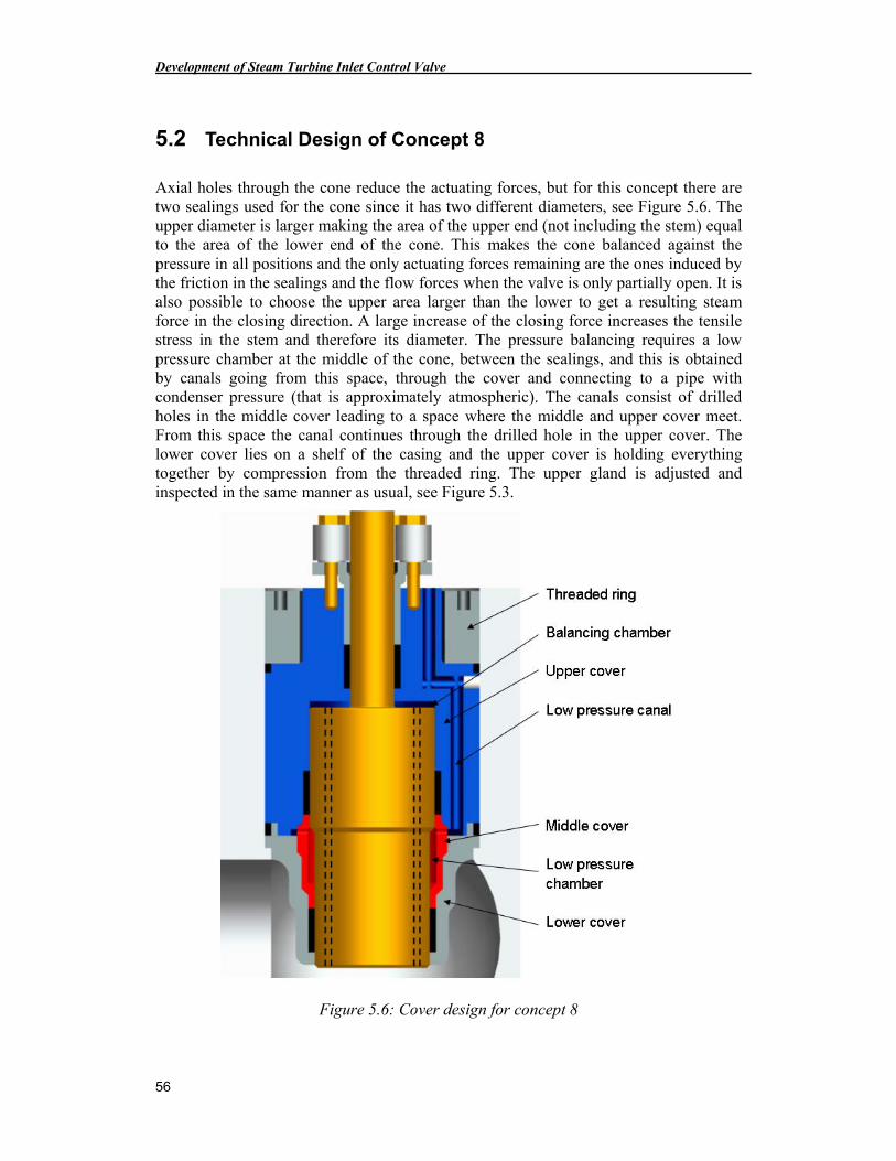
Development of Steam Turbine Inlet Control Valve
56
5.2 Technical Design of Concept 8
Axial holes through the cone reduce the actuating forces, but for this concept there are two sealings used for the cone since it has two different diameters, see Figure 5.6. The upper diameter is larger making the area of the upper end (not including the stem) equal to the area of the lower end of the cone. This makes the cone balanced against the pressure in all positions and the only actuating forces remaining are the ones induced by the friction in the sealings and the flow forces when the valve is only partially open. It is also possible to choose the upper area larger than the lower to get a resulting steam force in the closing direction. A large increase of the closing force increases the tensile stress in the stem and therefore its diameter. The pressure balancing requires a low pressure chamber at the middle of the cone, between the sealings, and this is obtained by canals going from this space, through the cover and connecting to a pipe with condenser pressure (that is approximately atmospheric). The canals consist of drilled holes in the middle cover leading to a space where the middle and upper cover meet. From this space the canal continues through the drilled hole in the upper cover. The lower cover lies on a shelf of the casing and the upper cover is holding everything together by compression from the threaded ring. The upper gland is adjusted and inspected in the same manner as usual, see Figure 5.3.
Figure 5.6: Cover design for concept 8
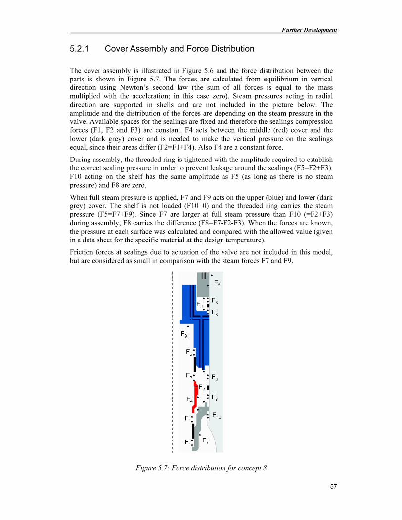
Further Development
57
5.2.1 Cover Assembly and Force Distribution
The cover assembly is illustrated in Figure 5.6 and the force distribution between the parts is shown in Figure 5.7. The forces are calculated from equilibrium in vertical direction using Newton’s second law (the sum of all forces is equal to the mass multiplied with the acceleration; in this case zero). Steam pressures acting in radial direction are supported in shells and are not included in the picture below. The amplitude and the distribution of the forces are depending on the steam pressure in the valve. Available spaces for the sealings are fixed and therefore the sealings compression forces (F1, F2 and F3) are constant. F4 acts between the middle (red) cover and the lower (dark grey) cover and is needed to make the vertical pressure on the sealings equal, since their areas differ (F2=F1+F4). Also F4 are a constant force.
During assembly, the threaded ring is tightened with the amplitude required to establish the correct sealing pressure in order to prevent leakage around the sealings (F5=F2+F3). F10 acting on the shelf has the same amplitude as F5 (as long as there is no steam pressure) and F8 are zero.
When full steam pressure is applied, F7 and F9 acts on the upper (blue) and lower (dark grey) cover. The shelf is not loaded (F10=0) and the threaded ring carries the steam pressure (F5=F7+F9). Since F7 are larger at full steam pressure than F10 (=F2+F3) during assembly, F8 carries the difference (F8=F7-F2-F3). When the forces are known, the pressure at each surface was calculated and compared with the allowed value (given in a data sheet for the specific material at the design temperature).
Friction forces at sealings due to actuation of the valve are not included in this model, but are considered as small in comparison with the steam forces F7 and F9.
Figure 5.7: Force distribution for concept 8
Development of Steam Turbine Inlet Control Valve
58
5.3 Technical Design of Concept 9
This concept is similar to concept 5. The difference is that concept 9 uses an accumulator instead of a spring to create the closing force.
5.3.1 Accumulator Volume
The accumulator volume was calculated according to Olsson & Rydberg (1993). With the assumptions of isotherm (constant temperature, slow process with heat transfer) charging and adiabatic (no heat transfer, quick process) discharging, the following formula may be applied using the nomenclatures in Table 5.1.
1
1
1
2
0
2
0
−
Δ=
n
p
p
p
pV
V
Table 5.1: Calculation of accumulator volume
Quantity Denomination Unit
V0 Accumulator volume [m3]
n Polytropic exponent [-]
p0 Preload pressure (90% of p1) [Pa]
p1 Minimum operational pressure [Pa]
p2 Maximum operational pressure [Pa]
The minimum operational pressure, p1, was multiplied with a safety factor to guarantee desired functionality due to friction and raised steam pressure etcetera. A polytropic exponent of 1,5 was used that is valid for nitrogen gas at 50 °C, according to standard procedure. The calculated accumulator volume is reasonable in size, about 20 liters, and the concept still seems to be competitive.
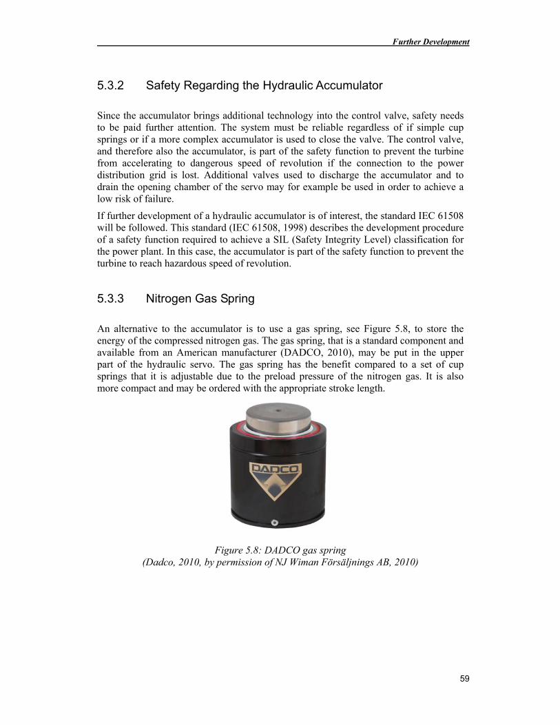
Further Development
59
5.3.2 Safety Regarding the Hydraulic Accumulator
Since the accumulator brings additional technology into the control valve, safety needs to be paid further attention. The system must be reliable regardless of if simple cup springs or if a more complex accumulator is used to close the valve. The control valve, and therefore also the accumulator, is part of the safety function to prevent the turbine from accelerating to dangerous speed of revolution if the connection to the power distribution grid is lost. Additional valves used to discharge the accumulator and to drain the opening chamber of the servo may for example be used in order to achieve a low risk of failure.
If further development of a hydraulic accumulator is of interest, the standard IEC 61508 will be followed. This standard (IEC 61508, 1998) describes the development procedure of a safety function required to achieve a SIL (Safety Integrity Level) classification for the power plant. In this case, the accumulator is part of the safety function to prevent the turbine to reach hazardous speed of revolution.
5.3.3 Nitrogen Gas Spring
An alternative to the accumulator is to use a gas spring, see Figure 5.8, to store the energy of the compressed nitrogen gas. The gas spring, that is a standard component and available from an American manufacturer (DADCO, 2010), may be put in the upper part of the hydraulic servo. The gas spring has the benefit compared to a set of cup springs that it is adjustable due to the preload pressure of the nitrogen gas. It is also more compact and may be ordered with the appropriate stroke length.
Figure 5.8: DADCO gas spring (Dadco, 2010, by permission of NJ Wiman Försäljnings AB, 2010)
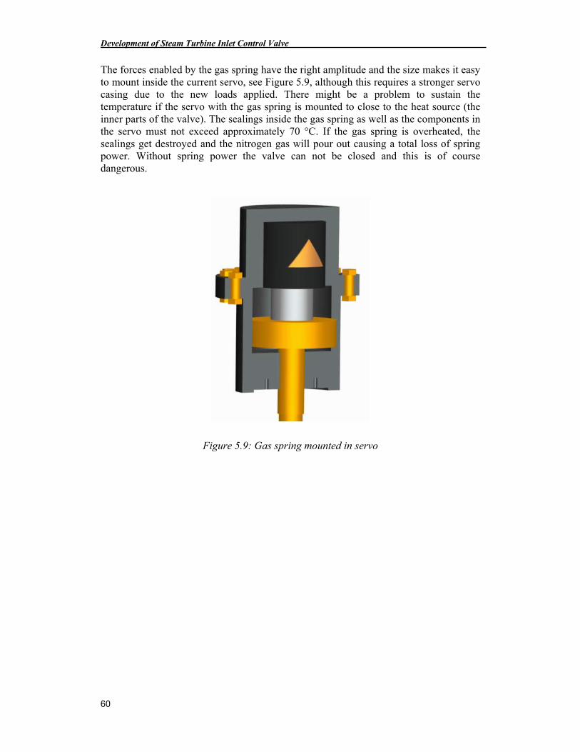
Development of Steam Turbine Inlet Control Valve
60
The forces enabled by the gas spring have the right amplitude and the size makes it easy to mount inside the current servo, see Figure 5.9, although this requires a stronger servo casing due to the new loads applied. There might be a problem to sustain the temperature if the servo with the gas spring is mounted to close to the heat source (the inner parts of the valve). The sealings inside the gas spring as well as the components in the servo must not exceed approximately 70 °C. If the gas spring is overheated, the sealings get destroyed and the nitrogen gas will pour out causing a total loss of spring power. Without spring power the valve can not be closed and this is of course dangerous.
Figure 5.9: Gas spring mounted in servo
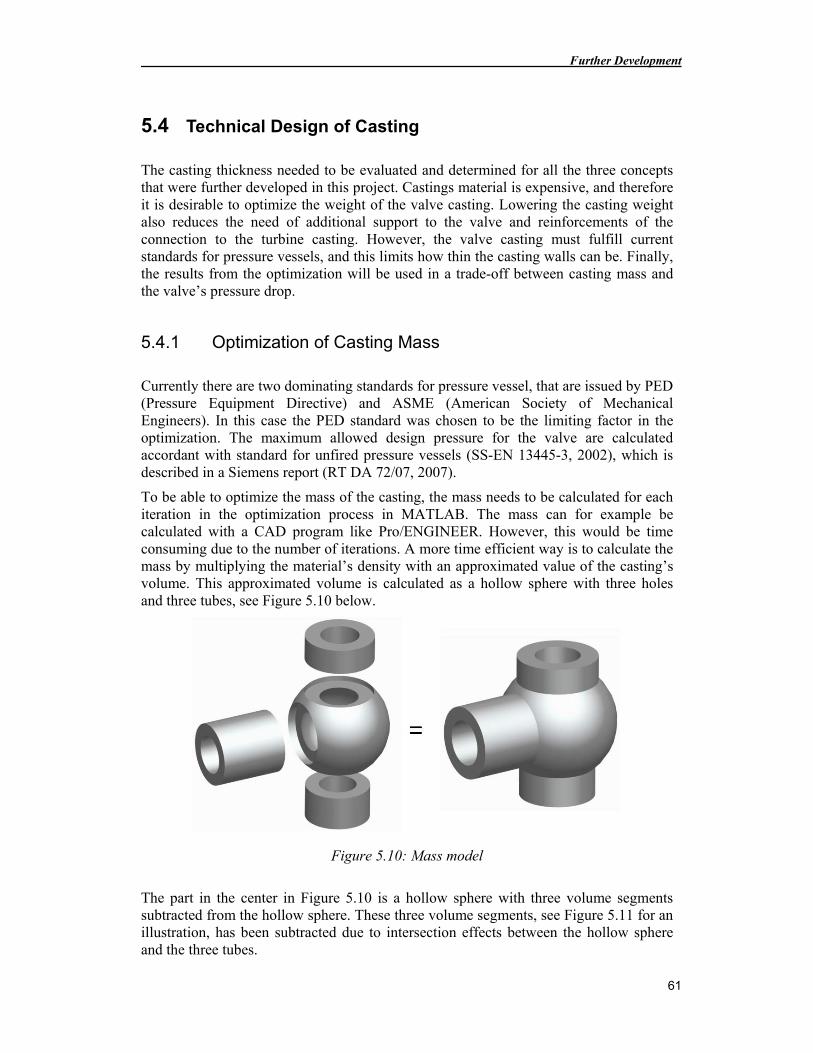
Further Development
61
5.4 Technical Design of Casting
The casting thickness needed to be evaluated and determined for all the three concepts that were further developed in this project. Castings material is expensive, and therefore it is desirable to optimize the weight of the valve casting. Lowering the casting weight also reduces the need of additional support to the valve and reinforcements of the connection to the turbine casting. However, the valve casting must fulfill current standards for pressure vessels, and this limits how thin the casting walls can be. Finally, the results from the optimization will be used in a trade-off between casting mass and the valve’s pressure drop.
5.4.1 Optimization of Casting Mass
Currently there are two dominating standards for pressure vessel, that are issued by PED (Pressure Equipment Directive) and ASME (American Society of Mechanical Engineers). In this case the PED standard was chosen to be the limiting factor in the optimization. The maximum allowed design pressure for the valve are calculated accordant with standard for unfired pressure vessels (SS-EN 13445-3, 2002), which is described in a Siemens report (RT DA 72/07, 2007).
To be able to optimize the mass of the casting, the mass needs to be calculated for each iteration in the optimization process in MATLAB. The mass can for example be calculated with a CAD program like Pro/ENGINEER. However, this would be time consuming due to the number of iterations. A more time efficient way is to calculate the mass by multiplying the material’s density with an approximated value of the casting’s volume. This approximated volume is calculated as a hollow sphere with three holes and three tubes, see Figure 5.10 below.
Figure 5.10: Mass model
The part in the center in Figure 5.10 is a hollow sphere with three volume segments subtracted from the hollow sphere. These three volume segments, see Figure 5.11 for an illustration, has been subtracted due to intersection effects between the hollow sphere and the three tubes.
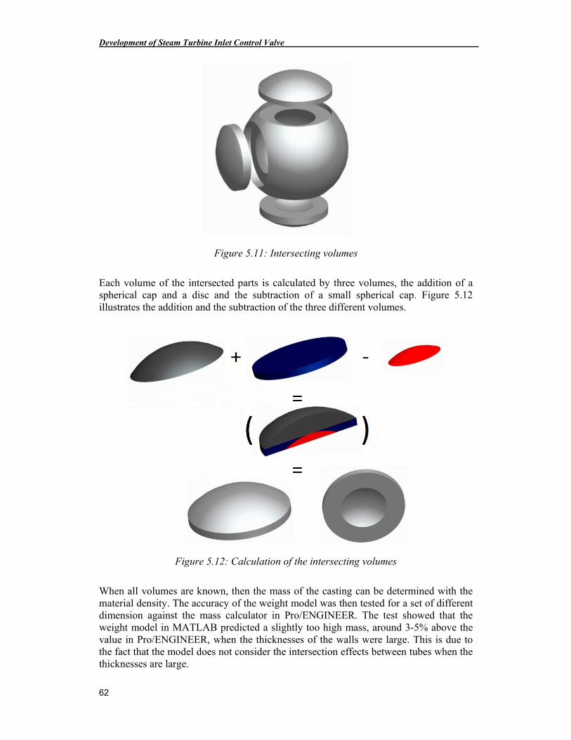
Development of Steam Turbine Inlet Control Valve
62
Figure 5.11: Intersecting volumes
Each volume of the intersected parts is calculated by three volumes, the addition of a spherical cap and a disc and the subtraction of a small spherical cap. Figure 5.12 illustrates the addition and the subtraction of the three different volumes.
Figure 5.12: Calculation of the intersecting volumes
When all volumes are known, then the mass of the casting can be determined with the material density. The accuracy of the weight model was then tested for a set of different dimension against the mass calculator in Pro/ENGINEER. The test showed that the weight model in MATLAB predicted a slightly too high mass, around 3-5% above the value in Pro/ENGINEER, when the thicknesses of the walls were large. This is due to the fact that the model does not consider the intersection effects between tubes when the thicknesses are large.
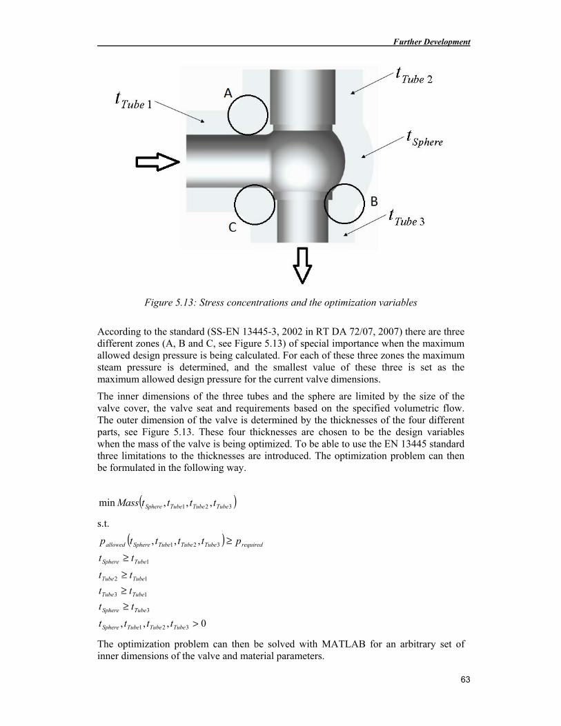
Further Development
63
Figure 5.13: Stress concentrations and the optimization variables
According to the standard (SS-EN 13445-3, 2002 in RT DA 72/07, 2007) there are three different zones (A, B and C, see Figure 5.13) of special importance when the maximum allowed design pressure is being calculated. For each of these three zones the maximum steam pressure is determined, and the smallest value of these three is set as the maximum allowed design pressure for the current valve dimensions.
The inner dimensions of the three tubes and the sphere are limited by the size of the valve cover, the valve seat and requirements based on the specified volumetric flow. The outer dimension of the valve is determined by the thicknesses of the four different parts, see Figure 5.13. These four thicknesses are chosen to be the design variables when the mass of the valve is being optimized. To be able to use the EN 13445 standard three limitations to the thicknesses are introduced. The optimization problem can then be formulated in the following way.
( )321 ,,,min TubeTubeTubeSphere ttttMass
s.t.
( )
0,,,
,,,
321
3
13
12
1
321
>
≥≥≥
≥
≥
TubeTubeTubeSphere
TubeSphere
TubeTube
TubeTube
TubeSphere
requiredTubeTubeTubeSphereallowed
tttt
tt
tt
tt
tt
pttttp
The optimization problem can then be solved with MATLAB for an arbitrary set of inner dimensions of the valve and material parameters.
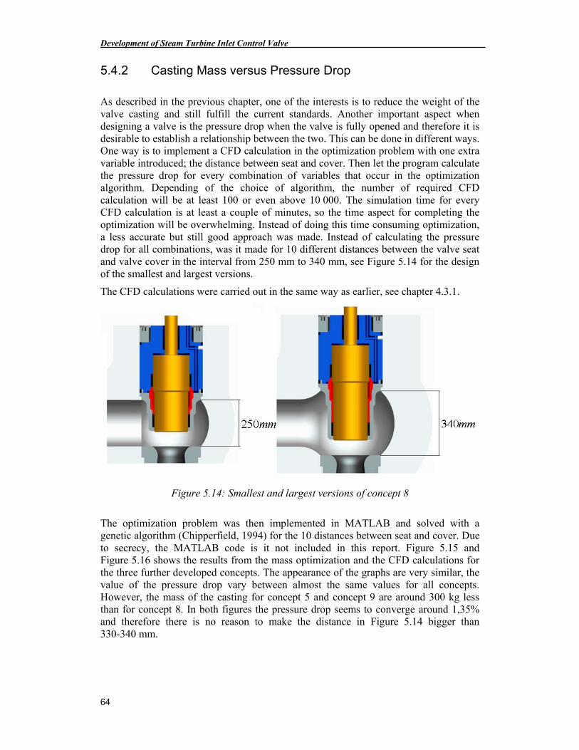
Development of Steam Turbine Inlet Control Valve
64
5.4.2 Casting Mass versus Pressure Drop
As described in the previous chapter, one of the interests is to reduce the weight of the valve casting and still fulfill the current standards. Another important aspect when designing a valve is the pressure drop when the valve is fully opened and therefore it is desirable to establish a relationship between the two. This can be done in different ways. One way is to implement a CFD calculation in the optimization problem with one extra variable introduced; the distance between seat and cover. Then let the program calculate the pressure drop for every combination of variables that occur in the optimization algorithm. Depending of the choice of algorithm, the number of required CFD calculation will be at least 100 or even above 10 000. The simulation time for every CFD calculation is at least a couple of minutes, so the time aspect for completing the optimization will be overwhelming. Instead of doing this time consuming optimization, a less accurate but still good approach was made. Instead of calculating the pressure drop for all combinations, was it made for 10 different distances between the valve seat and valve cover in the interval from 250 mm to 340 mm, see Figure 5.14 for the design of the smallest and largest versions.
The CFD calculations were carried out in the same way as earlier, see chapter 4.3.1.
Figure 5.14: Smallest and largest versions of concept 8
The optimization problem was then implemented in MATLAB and solved with a genetic algorithm (Chipperfield, 1994) for the 10 distances between seat and cover. Due to secrecy, the MATLAB code is it not included in this report. Figure 5.15 and Figure 5.16 shows the results from the mass optimization and the CFD calculations for the three further developed concepts. The appearance of the graphs are very similar, the value of the pressure drop vary between almost the same values for all concepts. However, the mass of the casting for concept 5 and concept 9 are around 300 kg less than for concept 8. In both figures the pressure drop seems to converge around 1,35% and therefore there is no reason to make the distance in Figure 5.14 bigger than 330-340 mm.
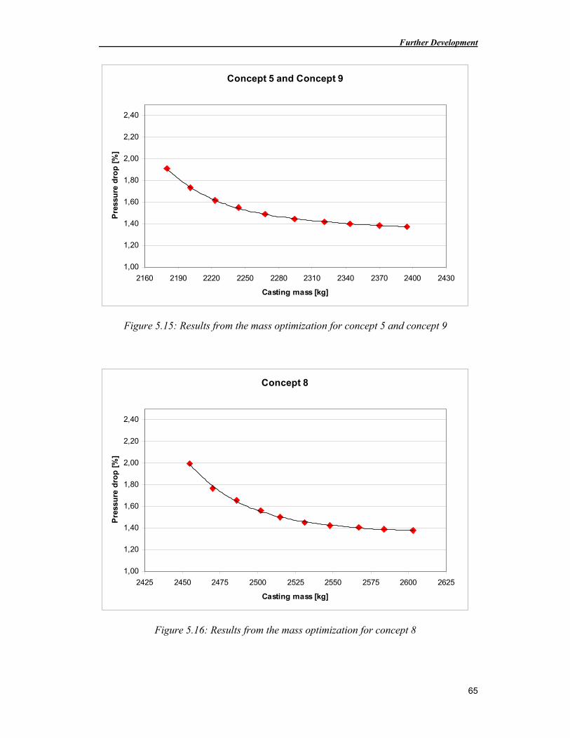
Further Development
65
Concept 5 and Concept 9
1,00
1,20
1,40
1,60
1,80
2,00
2,20
2,40
2160 2190 2220 2250 2280 2310 2340 2370 2400 2430
Casting mass [kg]
Pre
ssu
re d
rop
[%
]
Figure 5.15: Results from the mass optimization for concept 5 and concept 9
Concept 8
1,00
1,20
1,40
1,60
1,80
2,00
2,20
2,40
2425 2450 2475 2500 2525 2550 2575 2600 2625
Casting mass [kg]
Pre
ssu
re d
rop
[%
]
Figure 5.16: Results from the mass optimization for concept 8
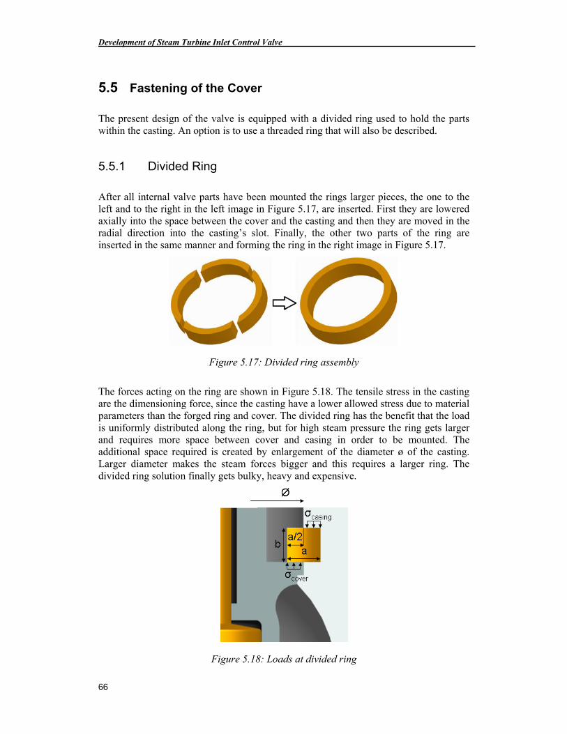
Development of Steam Turbine Inlet Control Valve
66
5.5 Fastening of the Cover
The present design of the valve is equipped with a divided ring used to hold the parts within the casting. An option is to use a threaded ring that will also be described.
5.5.1 Divided Ring
After all internal valve parts have been mounted the rings larger pieces, the one to the left and to the right in the left image in Figure 5.17, are inserted. First they are lowered axially into the space between the cover and the casting and then they are moved in the radial direction into the casting’s slot. Finally, the other two parts of the ring are inserted in the same manner and forming the ring in the right image in Figure 5.17.
Figure 5.17: Divided ring assembly
The forces acting on the ring are shown in Figure 5.18. The tensile stress in the casting are the dimensioning force, since the casting have a lower allowed stress due to material parameters than the forged ring and cover. The divided ring has the benefit that the load is uniformly distributed along the ring, but for high steam pressure the ring gets larger and requires more space between cover and casing in order to be mounted. The additional space required is created by enlargement of the diameter ø of the casting. Larger diameter makes the steam forces bigger and this requires a larger ring. The divided ring solution finally gets bulky, heavy and expensive.
Figure 5.18: Loads at divided ring
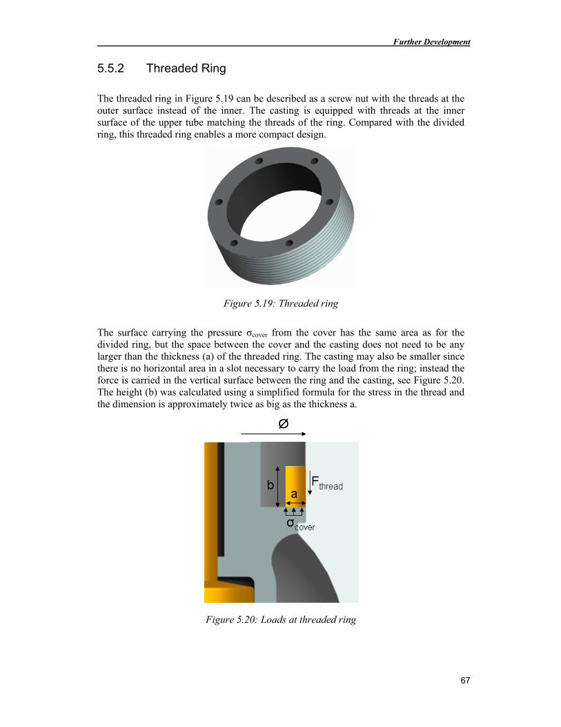
Further Development
67
5.5.2 Threaded Ring
The threaded ring in Figure 5.19 can be described as a screw nut with the threads at the outer surface instead of the inner. The casting is equipped with threads at the inner surface of the upper tube matching the threads of the ring. Compared with the divided ring, this threaded ring enables a more compact design.
Figure 5.19: Threaded ring
The surface carrying the pressure σcover from the cover has the same area as for the divided ring, but the space between the cover and the casting does not need to be any larger than the thickness (a) of the threaded ring. The casting may also be smaller since there is no horizontal area in a slot necessary to carry the load from the ring; instead the force is carried in the vertical surface between the ring and the casting, see Figure 5.20. The height (b) was calculated using a simplified formula for the stress in the thread and the dimension is approximately twice as big as the thickness a.
Figure 5.20: Loads at threaded ring
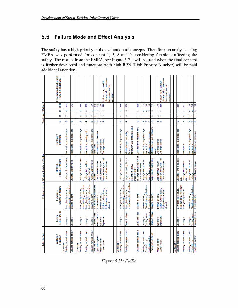
Development of Steam Turbine Inlet Control Valve
68
5.6 Failure Mode and Effect Analysis
The safety has a high priority in the evaluation of concepts. Therefore, an analysis using FMEA was performed for concept 1, 5, 8 and 9 considering functions affecting the safety. The results from the FMEA, see Figure 5.21, will be used when the final concept is further developed and functions with high RPN (Risk Priority Number) will be paid additional attention.
Figure 5.21: FMEA
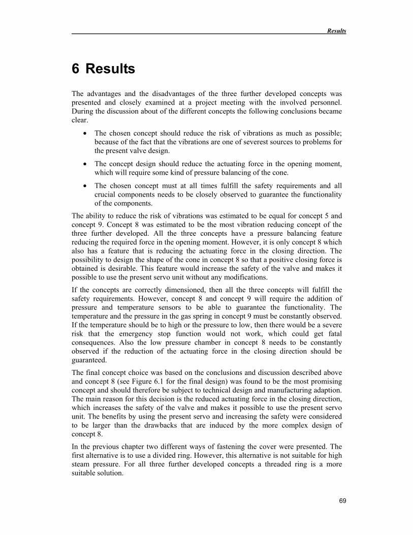
Results
69
6 Results
The advantages and the disadvantages of the three further developed concepts was presented and closely examined at a project meeting with the involved personnel. During the discussion about of the different concepts the following conclusions became clear.
• The chosen concept should reduce the risk of vibrations as much as possible; because of the fact that the vibrations are one of severest sources to problems for the present valve design.
• The concept design should reduce the actuating force in the opening moment, which will require some kind of pressure balancing of the cone.
• The chosen concept must at all times fulfill the safety requirements and all crucial components needs to be closely observed to guarantee the functionality of the components.
The ability to reduce the risk of vibrations was estimated to be equal for concept 5 and concept 9. Concept 8 was estimated to be the most vibration reducing concept of the three further developed. All the three concepts have a pressure balancing feature reducing the required force in the opening moment. However, it is only concept 8 which also has a feature that is reducing the actuating force in the closing direction. The possibility to design the shape of the cone in concept 8 so that a positive closing force is obtained is desirable. This feature would increase the safety of the valve and makes it possible to use the present servo unit without any modifications.
If the concepts are correctly dimensioned, then all the three concepts will fulfill the safety requirements. However, concept 8 and concept 9 will require the addition of pressure and temperature sensors to be able to guarantee the functionality. The temperature and the pressure in the gas spring in concept 9 must be constantly observed. If the temperature should be to high or the pressure to low, then there would be a severe risk that the emergency stop function would not work, which could get fatal consequences. Also the low pressure chamber in concept 8 needs to be constantly observed if the reduction of the actuating force in the closing direction should be guaranteed.
The final concept choice was based on the conclusions and discussion described above and concept 8 (see Figure 6.1 for the final design) was found to be the most promising concept and should therefore be subject to technical design and manufacturing adaption. The main reason for this decision is the reduced actuating force in the closing direction, which increases the safety of the valve and makes it possible to use the present servo unit. The benefits by using the present servo and increasing the safety were considered to be larger than the drawbacks that are induced by the more complex design of concept 8.
In the previous chapter two different ways of fastening the cover were presented. The first alternative is to use a divided ring. However, this alternative is not suitable for high steam pressure. For all three further developed concepts a threaded ring is a more suitable solution.
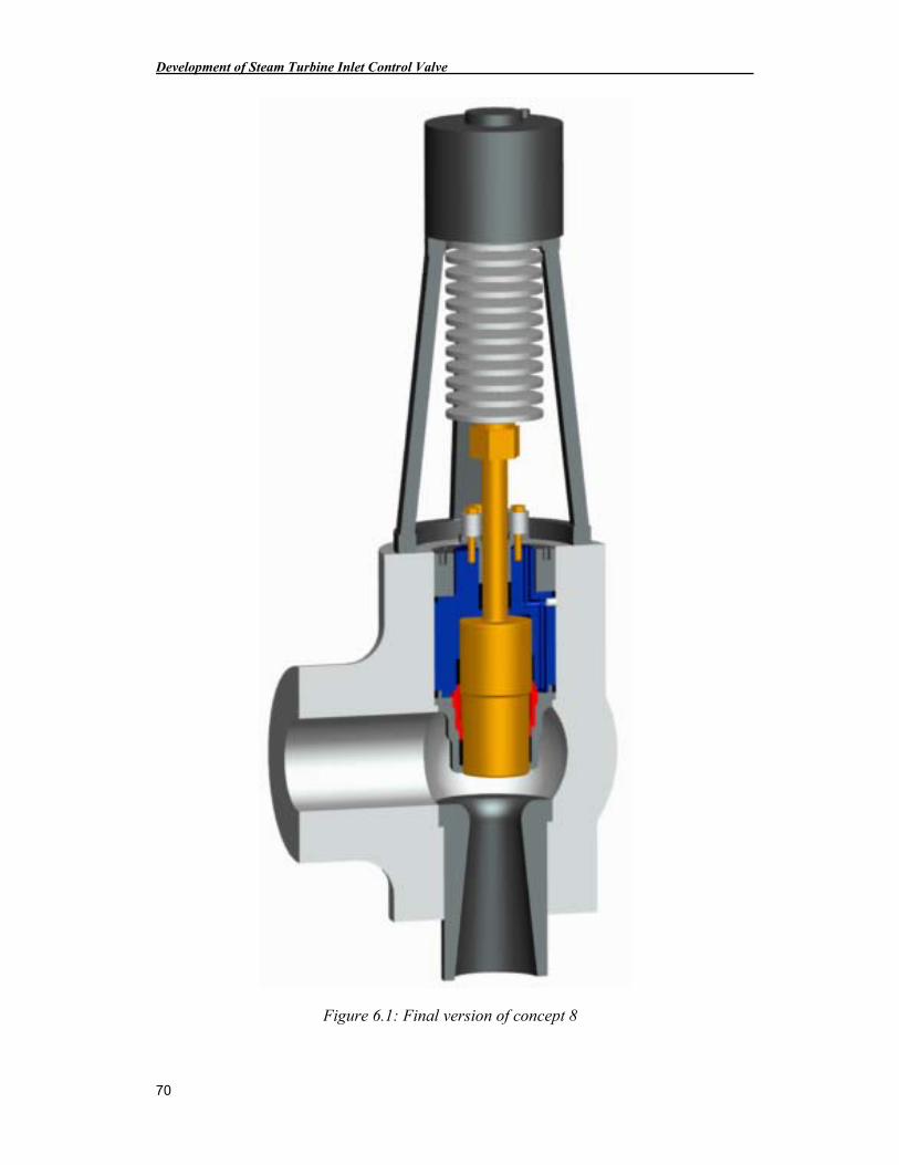
Development of Steam Turbine Inlet Control Valve
70
Figure 6.1: Final version of concept 8
Discussion
71
7 Discussion
This chapter contains reflections about the methods, used literature and the future work.
7.1 Method choices and its limitations
To let the conceptual design phase be performed by students has probably been wise. Since the students have a more limited knowledge about the present valves they are more likely to think beyond it and its design solutions.
In the early stages of the project the quality function deployment (QFD) method was used. However, the full potential of the method was not entirely explored. The method was primarily used as a discussion tool when the different relations between customer requirements and system characteristics were established. The result from the QFD was not used in the conceptual design. However, the work with the QFD was nevertheless necessary for the understanding of the different relationships. And the results from the QFD can still be used in the next stages of the project, when the technical design gets more mature and different system characteristics will be put against each other. The result from the pairwise comparison, which was developed for the QFD, was used during all concept choices in the project’s process. The pairwise comparison is a simple way to rank different customer requirements against each other. However, the method has a drawback; it only takes into account if a requirement is less, equal or more important than another one, but not how much more (or less) important.
The relative decision matrices used in this project have been useful when the original 15 concepts were reduced to only three to further develop. However, the relative decision matrix has the same drawback as the pairwise comparison method; it does not take into account how much more one concept are satisfying a criteria compared to other ones.
7.2 Literature limitations
The selection of literature and sources within the area of steam turbine inlet control valves is quite limited and consists mainly of internal knowledge at the steam turbine manufacturing companies. A lot of the information is of the type that can not be acquired by reading a book; instead it needs to be obtained by years of experience. Far from all of the experience based on knowledge has a good foundation in the literature.
The access to other manufactures’ design solutions has been limited and only old solutions have been able to be investigated. Therefore, many of the developed concepts have been inspired by different designs that SIT AB has access to. Another aspect that may have affected the development process is that all necessary literature and material were not available from the beginning of the project and have been introduced at different stages of the project. If some of the material had been acquired earlier in the project, then a couple of other concepts may likely have been presented with the original 15. However, this would probably not have affected the final result of the project, even if the way to the result probably should have been a little bit different.
Development of Steam Turbine Inlet Control Valve
72
7.3 Future Work
The new and complex design of concept 8 creates the following a set of areas that needs to be more investigated before the final design of concept 8 is ready for production.
• One of the central problems for the functionality of concept 8 is the sealings around the cone that is enclosing the low pressure chamber. If leakages over these two sealings are too big, then concept 8 will not function as designed. To work correctly the sealings need be compressed, either by a suitable force or by dimensioning of the space in which the sealings are to be mounted. The present calculation model for the sealing is based on the relation between the steam pressure and the required gland pressure. Concept 8 will require a new model for the sealing that is based on the relation between the steam pressure and the compression rate of the sealing.
• Another area of interest is the gradually lose of sealing ability that occur especially in the beginning of the sealing’s life. One way to counteract this problem is to use an adjustable gland pressure unit. However, this is not a feasible option for the two sealings enclosing the low pressure chamber in concept 8, due to the limited space in the valve cover. Another way to solve the problem could be to preload the sealing with an extra high gland pressure and after a while when the sealing has became thinner, the correct gland pressure would have been obtained. A third way of solving the problem could be to “pre-bake” the sealings at high temperature and high gland pressure before they are installed in the valve. The two feasible solutions would require more knowledge about the behavior of the sealings.
• The new shape of the flow chamber and cone will require the development of a new force model that describes the relation between the valve stroke and the resulting force on the cone, due to the steam’s flow and pressure. This can be done with CFD calculation or with a prototype of the new valve. Probably it will require involvement from both methods if a good and accurate model should be acquired.
• The assumed temperature differences (that occurs at startup and shutdown) between and within different parts of the valve cover are another important aspect that needs to be considered. The temperature expansion of the material can cause the cone to get wedged in the cover, if the temperature differences get to large. To counteract this effect the different parts need to be carefully dimensioned and the cone probably needs to be partially hollow to reduce the mass that can accumulate heat energy.
• The choice of material has not definitively been settled during this master thesis project and the choice needs to be done within a near future. This choice needs to be done concordant with choice of material to the steam turbine. Also the question of, if and where coating of the material should be used has not been determined during this project.
• The failure mode and effect analysis that was made for the further developed concepts needs to be expanded for concept 8 and updated with more details and all other components in the valve.
Conclusions
73
8 Conclusions
The main problem for the present design with the introduction of the higher pressure is that the force requirements gets unreasonable large. Pressure balancing was therefore a major tactic during the concept development process. This feature was more or less a new way, within the company, to meet the demands induced by the higher pressure. Although the market for steam turbines is usually fairly conservative concerning new technology, this new and more complex design has received mostly positive feedback from the project leaders at Siemens. Due to the pressure balancing feature and the radial support from the added packing around the cone, the vibration problems will most likely be significantly reduced.
The new valve design will probably meet the requirements and has the potential to be refined for even higher pressure for future demands.

Bibliography
75
9 Bibliography
Çengel Y.A., Turner R.H., Fundamentals of Thermal-Fluid Sciences, Second edition, McGraw-Hill, New York, 2005
Danielsen H.K., Hald J., Influence of Z-phase on Long-term Creep Stability of Martensitic 9-12% Cr Steels, Denmark, 2009
DIN 2093, Discs Springs, German Institute for Standardization, Germany, 2006
Gorla R.S.R., Khan A.A., Turbomachinery Design and Theory, Marcel Dekker, New York, 2003
Hald J., Creep Resistant 9-12% Cr Steels – Long-term testing, Microstructure stability and development potentials, Denmark, 2005
IEC 61508, Functional Safety of Electrical / Electronic / Programmable Electronic Safety-related Systems, International Electrotechnical Commission, Switzerland, 1998
Johannesson H., Persson J.G., Pettersson D., Produktutveckling – effektiva metoder för konstruktion och design, Liber AB, Stockholm, 2004
Klotz H., Davis K., Pickering E., Designing an Ultrasupercritical Steam Turbine, Power Magazine, 2009
Logan E. Jr., Ramendra R., Handbook of Turbomachinery, Second edition, Marcel Dekker, New York, 2003
Olsson O., Rydberg K.E., Kompendium i Hydraulik, Department of Management and Engineering, Linköpings University, 1993
Pugh S., Total Design: Integrated Methods for Successful Product Engineering, Addison-Wesley, Wokingham, 1990
RT DA 72/07, Calculation of Design Curves for Control Valves, Siemens Internal Report, 2007
SS-EN 13445-3, Unfired pressure vessels, European standard, 2002
Ullman D.G., The Mechanical Design Process, Third Edition, McGraw-Hill, New York, 2003
Zhang Y., Bates B., Wang Y.Q., Pint B.A., A Novel Low-Temperature Diffusion Aluminide Coating for Ultrasupercritical Coal-Fired Boiler Applications, Pittsburgh, 2008
Ölvander J., Design Optimization, Linköping University, Sweden, 2010
Development of Steam Turbine Inlet Control Valve
76
Dadco, http://www.dadcocanada.com/, 2010-05-26
Garlock Sealing Technologies, http://www.garlock.com/, 2010-02-23
Mubea, http://www.mubea.com/, 2010-04-07
NJ Wiman Försäljnings AB, http://njwiman.se/, 2010-05-26
Siemens Industrial Turbomachinery AB, http://www.sit-ab.se/, 2010-02-24
Wikipedia, http://en.wikipedia.org/wiki/Heron_of_Alexandria, 2010-06-11
Chipperfield A., Simple Genetic Algorithm part of the Genetic Algorithm Toolbox (GATbx), University of Sheffield, England, 1994 (modified by Johan Andersson, Linköping University, 2004)
Appendix
77
10 Appendix
10.1 Appendix A: Product Design Specification
D stands for demand and W stands for wish in the PDS.
10.1.1 Function Limited Requirements
• Sustain high temperature ≥ T1 °C (T2 °C)1 D
• Sustain high pressure ≥ p bar D
• Design for volumetric flow ≥ V m3/s D
• Control valve pressure loss ≤ X% D
• The force from the servo unit should be adequate D to secure a controlled movement of the valve.
10.1.2 Security Requirements
• The inlet arrangement with CV and ESV must D at least have two independent emergency stop functions.
• The CV should have an emergency stop function. W
• It should be impossible for any valve parts to D enter the turbine inlet.
• Large leakage of steam should be impossible. D
• Steam leakage from the valves should be impossible. W
1 T2 °C only if technical solution compared with T1 °C does not bring tremendous design changes and that it is based on existing proven design.
Development of Steam Turbine Inlet Control Valve
78
10.1.3 Solid Mechanics and Material Requirements
• Lifetime ≥ 200 000 h W
• Lifetime ≥ 100 000 h D
• Service interval ≥ 5 years D
• The valve casing should fulfill current standards D for pressure vessel, PED & ASME.
• All parts of the valve should be designed and dimensioned D with respect to fatigue failure and creep strength.
• The CV and the ESV should be manufacture of D materials that sustains the high temperature without failure.
• The material should be 9-12% Cr Steel alloys, due to W material cost and earlier experience.
• The valve surfaces must resist oxidation at high temperature. D
10.1.4 Environmental Requirements
• The valve shouldn’t exist of any parts that are W harmful to the environment.
• The product should be recyclable / reusable. D
Appendix
79
10.1.5 Overall Design Requirements
• The design should be as compact as possible. W
• The valves must fit in the space that is limited D by other components in the steam power plant.
• Small design change between left and right W assembly of the valve.
• It should be easy to assemble and disassemble W the valves.
• To be able to service the steam turbine, the D CV must be possible disassemble.
• When it’s possible existing components D should be used.
• Use existing proven design solutions. W
• The design of the valve should reduce the W the risk of vibrations.
• Standard components from suppliers should W be used instead of non-standard components.
• Avoid expensive design solutions. W
• The weight of the valve should be as low as possible. W
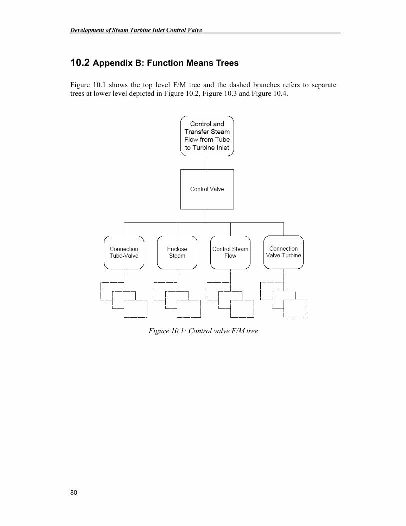
Development of Steam Turbine Inlet Control Valve
80
10.2 Appendix B: Function Means Trees
Figure 10.1 shows the top level F/M tree and the dashed branches refers to separate trees at lower level depicted in Figure 10.2, Figure 10.3 and Figure 10.4.
Figure 10.1: Control valve F/M tree
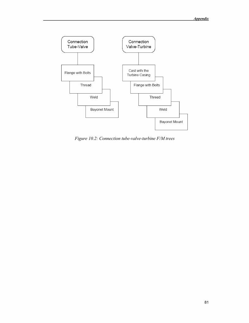
Appendix
81
Figure 10.2: Connection tube-valve-turbine F/M trees
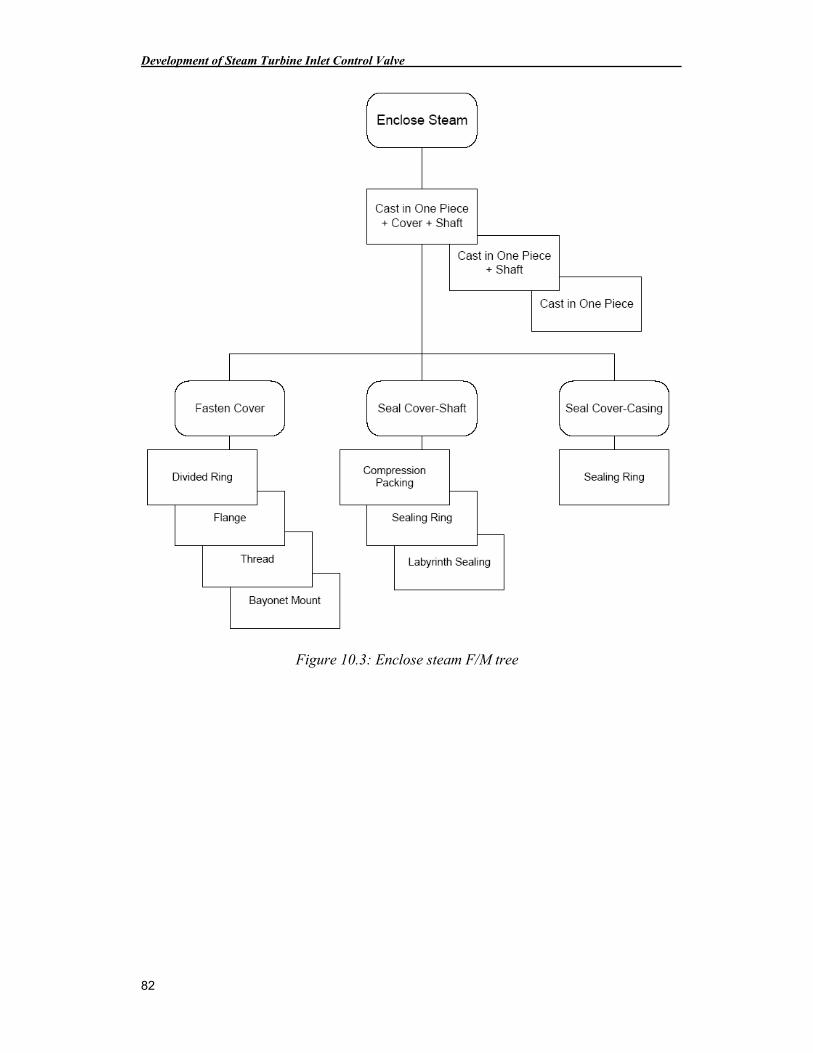
Development of Steam Turbine Inlet Control Valve
82
Figure 10.3: Enclose steam F/M tree
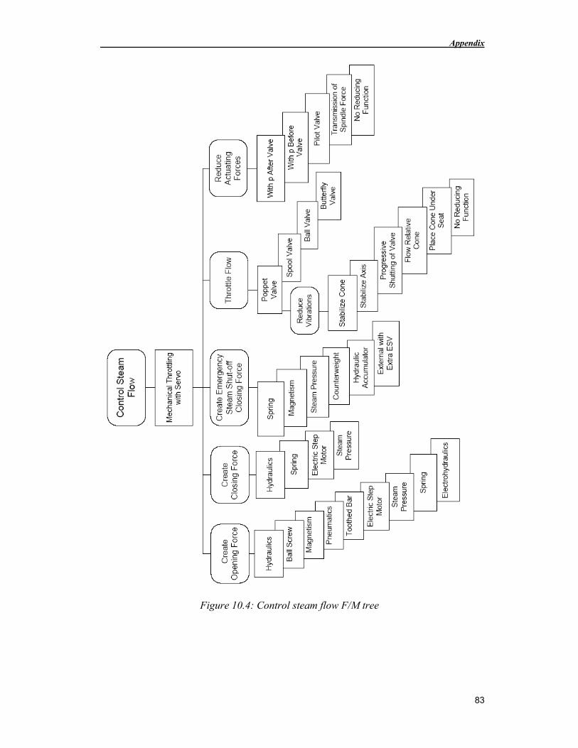
Appendix
83
Figure 10.4: Control steam flow F/M tree
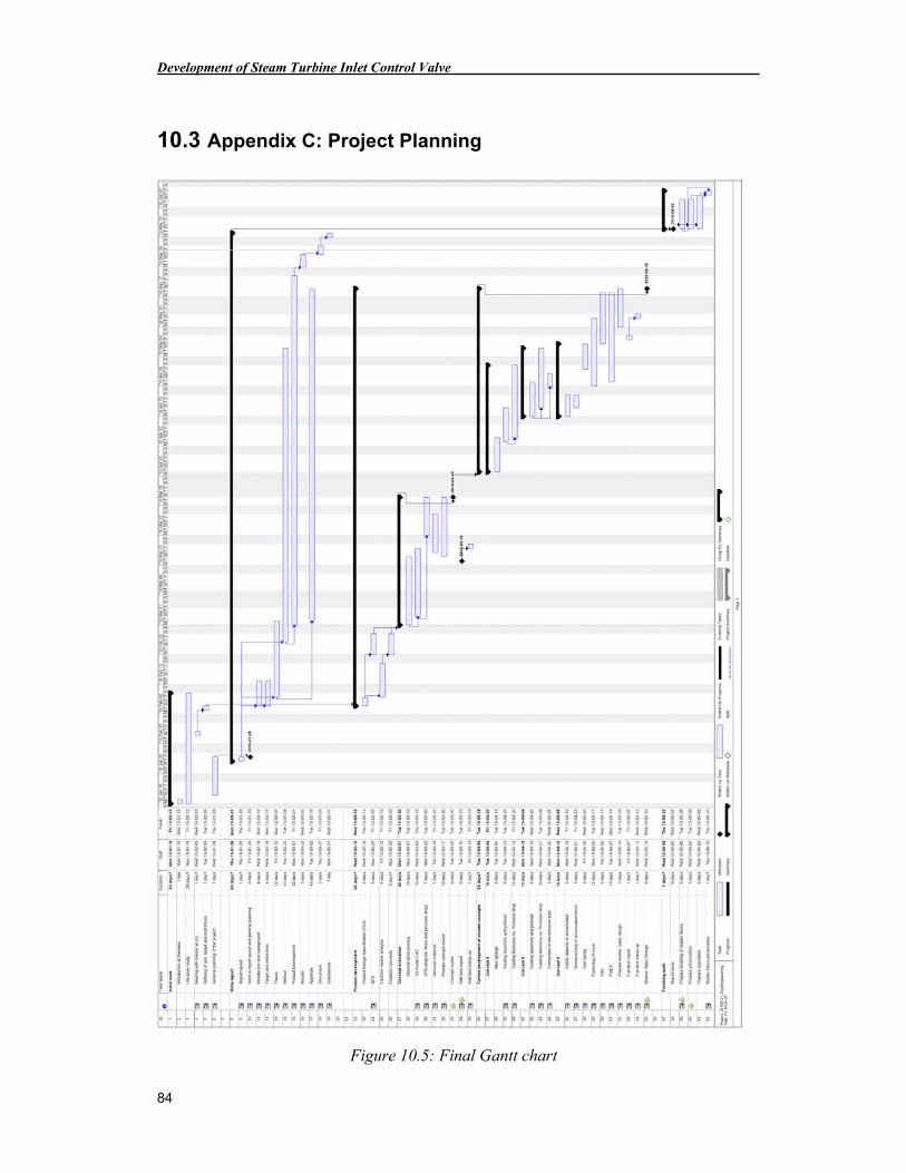
Development of Steam Turbine Inlet Control Valve
84
10.3 Appendix C: Project Planning
Figure 10.5: Final Gantt chart
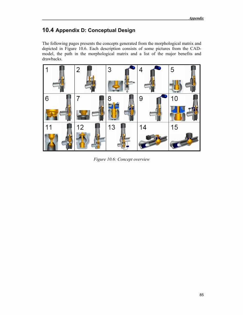
Appendix
85
10.4 Appendix D: Conceptual Design
The following pages presents the concepts generated from the morphological matrix and depicted in Figure 10.6. Each description consists of some pictures from the CAD-model, the path in the morphological matrix and a list of the major benefits and drawbacks.
Figure 10.6: Concept overview
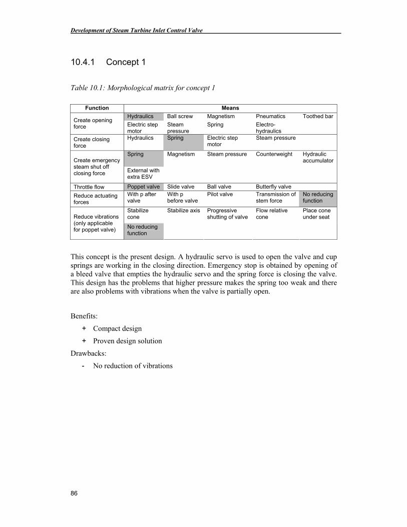
Development of Steam Turbine Inlet Control Valve
86
10.4.1 Concept 1
Table 10.1: Morphological matrix for concept 1
Function Means
Hydraulics Ball screw Magnetism Pneumatics Toothed bar Create opening force Electric step
motor Steam pressure
Spring Electro-hydraulics
Create closing force
Hydraulics Spring Electric step motor
Steam pressure
Spring Magnetism Steam pressure Counterweight Hydraulic accumulator Create emergency
steam shut off closing force External with
extra ESV
Throttle flow Poppet valve Slide valve Ball valve Butterfly valve
Reduce actuating forces
With p after valve
With p before valve
Pilot valve Transmission of stem force
No reducing function
Stabilize cone
Stabilize axis Progressive shutting of valve
Flow relative cone
Place cone under seat Reduce vibrations
(only applicable for poppet valve) No reducing
function
This concept is the present design. A hydraulic servo is used to open the valve and cup springs are working in the closing direction. Emergency stop is obtained by opening of a bleed valve that empties the hydraulic servo and the spring force is closing the valve. This design has the problems that higher pressure makes the spring too weak and there are also problems with vibrations when the valve is partially open.
Benefits:
+ Compact design
+ Proven design solution
Drawbacks:
- No reduction of vibrations
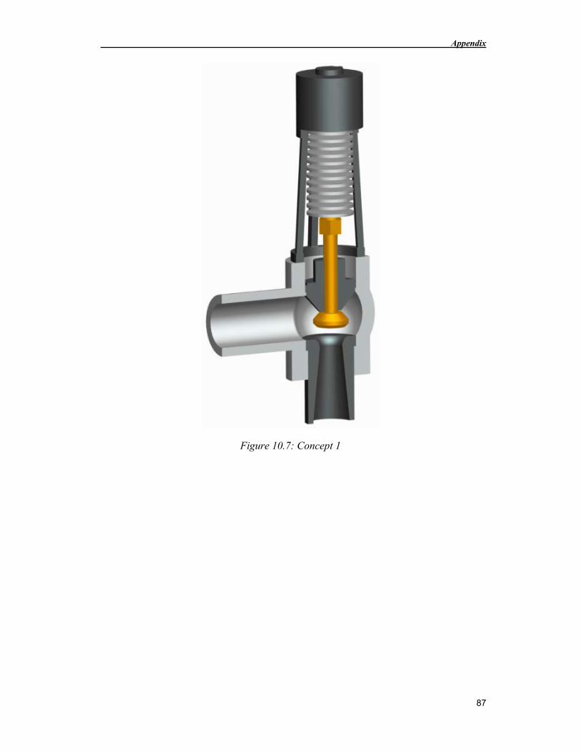
Appendix
87
Figure 10.7: Concept 1
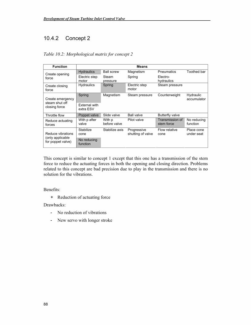
Development of Steam Turbine Inlet Control Valve
88
10.4.2 Concept 2
Table 10.2: Morphological matrix for concept 2
Function Means
Hydraulics Ball screw Magnetism Pneumatics Toothed bar Create opening force Electric step
motor Steam pressure
Spring Electro-hydraulics
Create closing force
Hydraulics Spring Electric step motor
Steam pressure
Spring Magnetism Steam pressure Counterweight Hydraulic accumulator Create emergency
steam shut off closing force External with
extra ESV
Throttle flow Poppet valve Slide valve Ball valve Butterfly valve
Reduce actuating forces
With p after valve
With p before valve
Pilot valve Transmission of stem force
No reducing function
Stabilize cone
Stabilize axis Progressive shutting of valve
Flow relative cone
Place cone under seat Reduce vibrations
(only applicable for poppet valve) No reducing
function
This concept is similar to concept 1 except that this one has a transmission of the stem force to reduce the actuating forces in both the opening and closing direction. Problems related to this concept are bad precision due to play in the transmission and there is no solution for the vibrations.
Benefits:
+ Reduction of actuating force
Drawbacks:
- No reduction of vibrations
- New servo with longer stroke
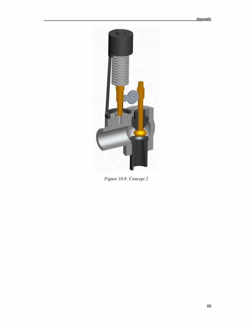
Appendix
89
Figure 10.8: Concept 2
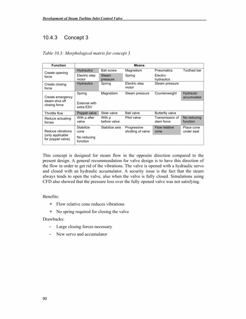
Development of Steam Turbine Inlet Control Valve
90
10.4.3 Concept 3
Table 10.3: Morphological matrix for concept 3
Function Means
Hydraulics Ball screw Magnetism Pneumatics Toothed bar Create opening force Electric step
motor Steam pressure
Spring Electro-hydraulics
Create closing force
Hydraulics Spring Electric step motor
Steam pressure
Spring Magnetism Steam pressure Counterweight Hydraulic accumulator Create emergency
steam shut off closing force External with
extra ESV
Throttle flow Poppet valve Slide valve Ball valve Butterfly valve
Reduce actuating forces
With p after valve
With p before valve
Pilot valve Transmission of stem force
No reducing function
Stabilize cone
Stabilize axis Progressive shutting of valve
Flow relative cone
Place cone under seat Reduce vibrations
(only applicable for poppet valve) No reducing
function
This concept is designed for steam flow in the opposite direction compared to the present design. A general recommendation for valve design is to have this direction of the flow in order to get rid of the vibrations. The valve is opened with a hydraulic servo and closed with an hydraulic accumulator. A security issue is the fact that the steam always tends to open the valve, also when the valve is fully closed. Simulations using CFD also showed that the pressure loss over the fully opened valve was not satisfying.
Benefits:
+ Flow relative cone reduces vibrations
+ No spring required for closing the valve
Drawbacks:
- Large closing forces necessary
- New servo and accumulator
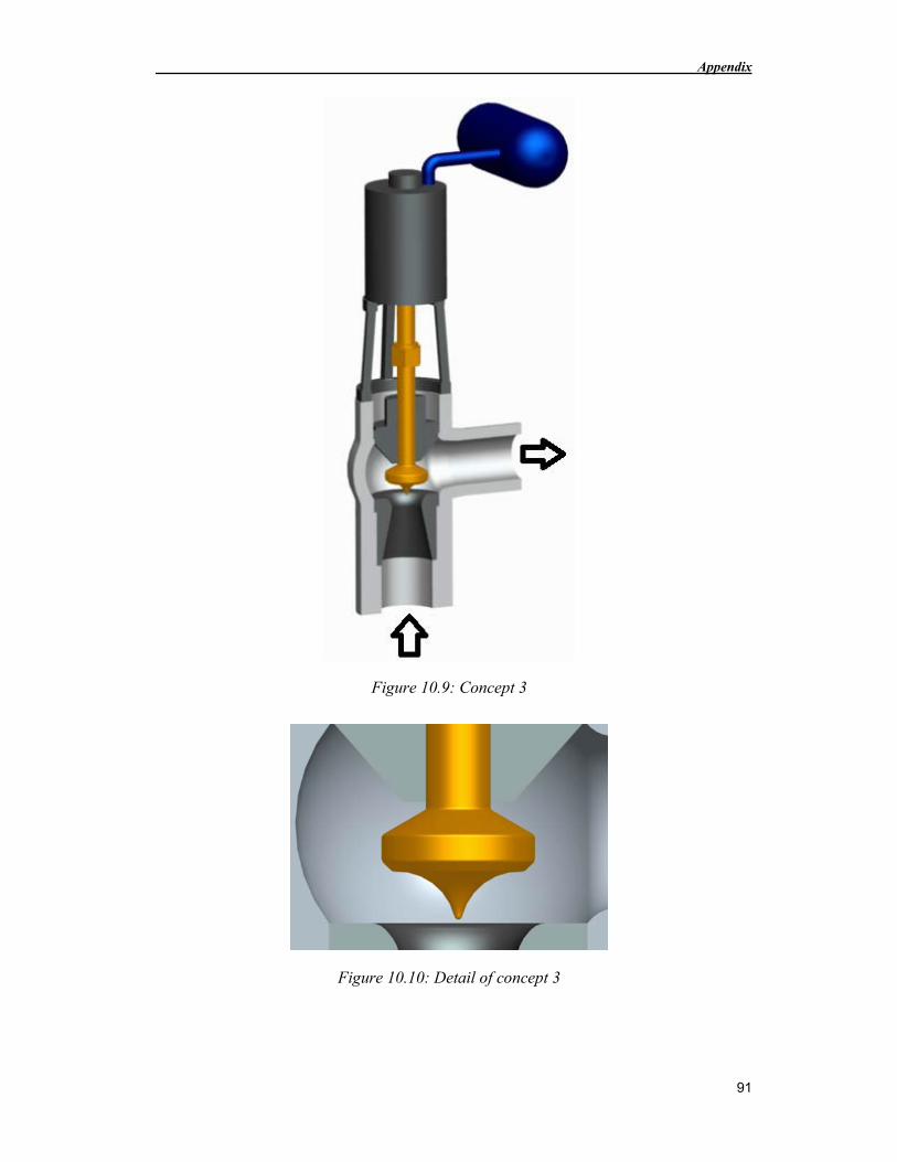
Appendix
91
Figure 10.9: Concept 3
Figure 10.10: Detail of concept 3
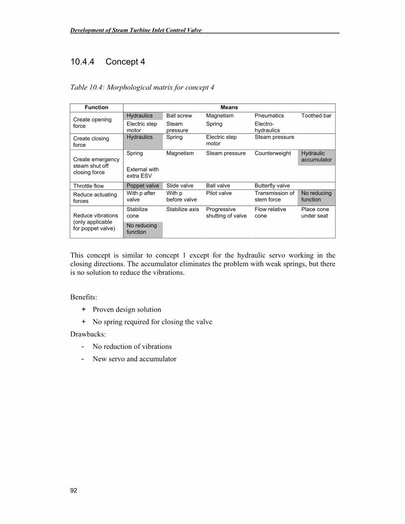
Development of Steam Turbine Inlet Control Valve
92
10.4.4 Concept 4
Table 10.4: Morphological matrix for concept 4
Function Means
Hydraulics Ball screw Magnetism Pneumatics Toothed bar Create opening force Electric step
motor Steam pressure
Spring Electro-hydraulics
Create closing force
Hydraulics Spring Electric step motor
Steam pressure
Spring Magnetism Steam pressure Counterweight Hydraulic accumulator Create emergency
steam shut off closing force External with
extra ESV
Throttle flow Poppet valve Slide valve Ball valve Butterfly valve
Reduce actuating forces
With p after valve
With p before valve
Pilot valve Transmission of stem force
No reducing function
Stabilize cone
Stabilize axis Progressive shutting of valve
Flow relative cone
Place cone under seat Reduce vibrations
(only applicable for poppet valve) No reducing
function
This concept is similar to concept 1 except for the hydraulic servo working in the closing directions. The accumulator eliminates the problem with weak springs, but there is no solution to reduce the vibrations.
Benefits:
+ Proven design solution
+ No spring required for closing the valve
Drawbacks:
- No reduction of vibrations
- New servo and accumulator
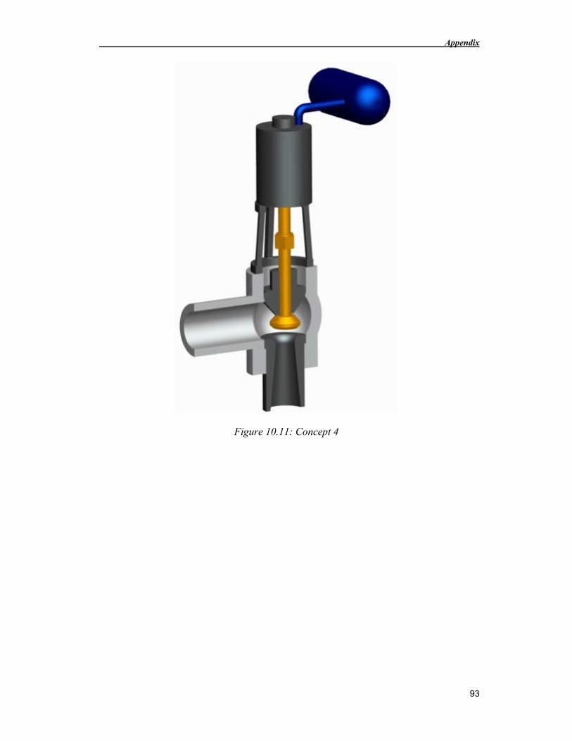
Appendix
93
Figure 10.11: Concept 4
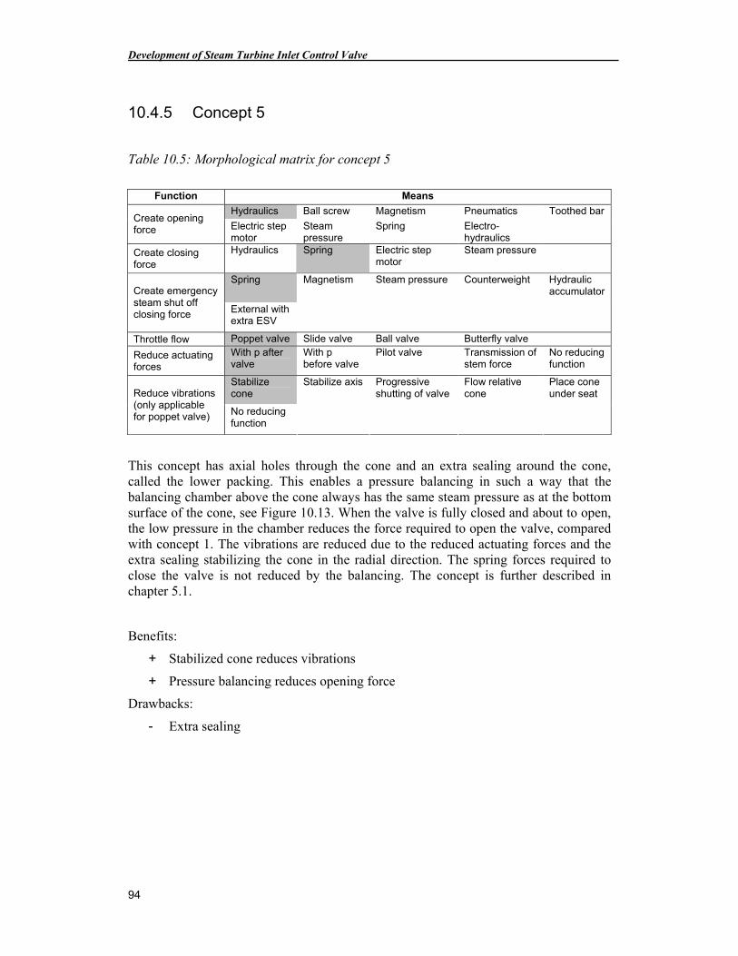
Development of Steam Turbine Inlet Control Valve
94
10.4.5 Concept 5
Table 10.5: Morphological matrix for concept 5
Function Means
Hydraulics Ball screw Magnetism Pneumatics Toothed bar Create opening force Electric step
motor Steam pressure
Spring Electro-hydraulics
Create closing force
Hydraulics Spring Electric step motor
Steam pressure
Spring Magnetism Steam pressure Counterweight Hydraulic accumulator Create emergency
steam shut off closing force External with
extra ESV
Throttle flow Poppet valve Slide valve Ball valve Butterfly valve
Reduce actuating forces
With p after valve
With p before valve
Pilot valve Transmission of stem force
No reducing function
Stabilize cone
Stabilize axis Progressive shutting of valve
Flow relative cone
Place cone under seat Reduce vibrations
(only applicable for poppet valve) No reducing
function
This concept has axial holes through the cone and an extra sealing around the cone, called the lower packing. This enables a pressure balancing in such a way that the balancing chamber above the cone always has the same steam pressure as at the bottom surface of the cone, see Figure 10.13. When the valve is fully closed and about to open, the low pressure in the chamber reduces the force required to open the valve, compared with concept 1. The vibrations are reduced due to the reduced actuating forces and the extra sealing stabilizing the cone in the radial direction. The spring forces required to close the valve is not reduced by the balancing. The concept is further described in chapter 5.1.
Benefits:
+ Stabilized cone reduces vibrations
+ Pressure balancing reduces opening force
Drawbacks:
- Extra sealing
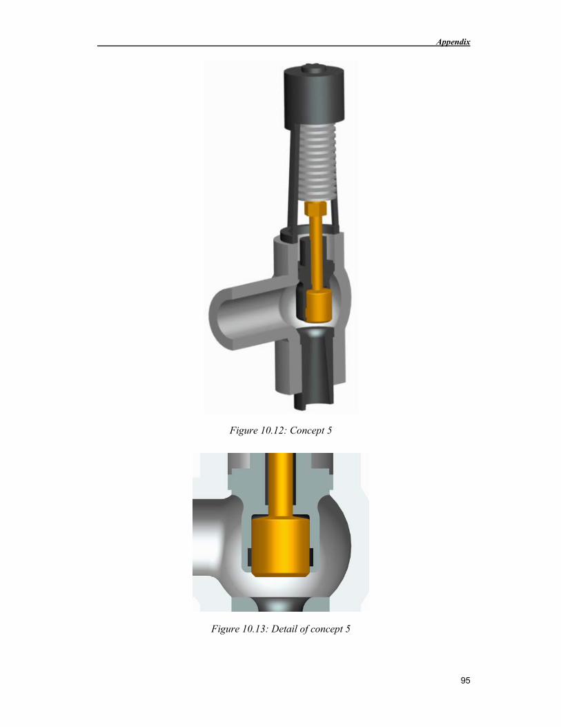
Appendix
95
Figure 10.12: Concept 5
Figure 10.13: Detail of concept 5
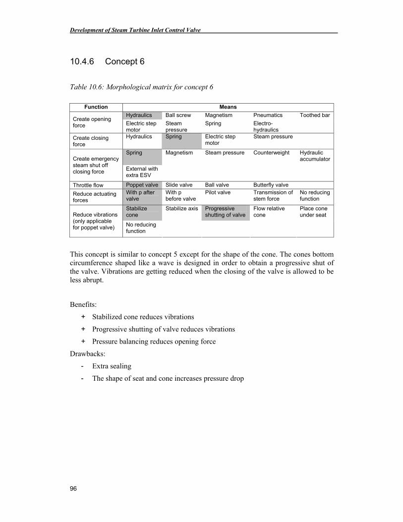
Development of Steam Turbine Inlet Control Valve
96
10.4.6 Concept 6
Table 10.6: Morphological matrix for concept 6
Function Means
Hydraulics Ball screw Magnetism Pneumatics Toothed bar Create opening force Electric step
motor Steam pressure
Spring Electro-hydraulics
Create closing force
Hydraulics Spring Electric step motor
Steam pressure
Spring Magnetism Steam pressure Counterweight Hydraulic accumulator Create emergency
steam shut off closing force External with
extra ESV
Throttle flow Poppet valve Slide valve Ball valve Butterfly valve
Reduce actuating forces
With p after valve
With p before valve
Pilot valve Transmission of stem force
No reducing function
Stabilize cone
Stabilize axis Progressive shutting of valve
Flow relative cone
Place cone under seat Reduce vibrations
(only applicable for poppet valve) No reducing
function
This concept is similar to concept 5 except for the shape of the cone. The cones bottom circumference shaped like a wave is designed in order to obtain a progressive shut of the valve. Vibrations are getting reduced when the closing of the valve is allowed to be less abrupt.
Benefits:
+ Stabilized cone reduces vibrations
+ Progressive shutting of valve reduces vibrations
+ Pressure balancing reduces opening force
Drawbacks:
- Extra sealing
- The shape of seat and cone increases pressure drop
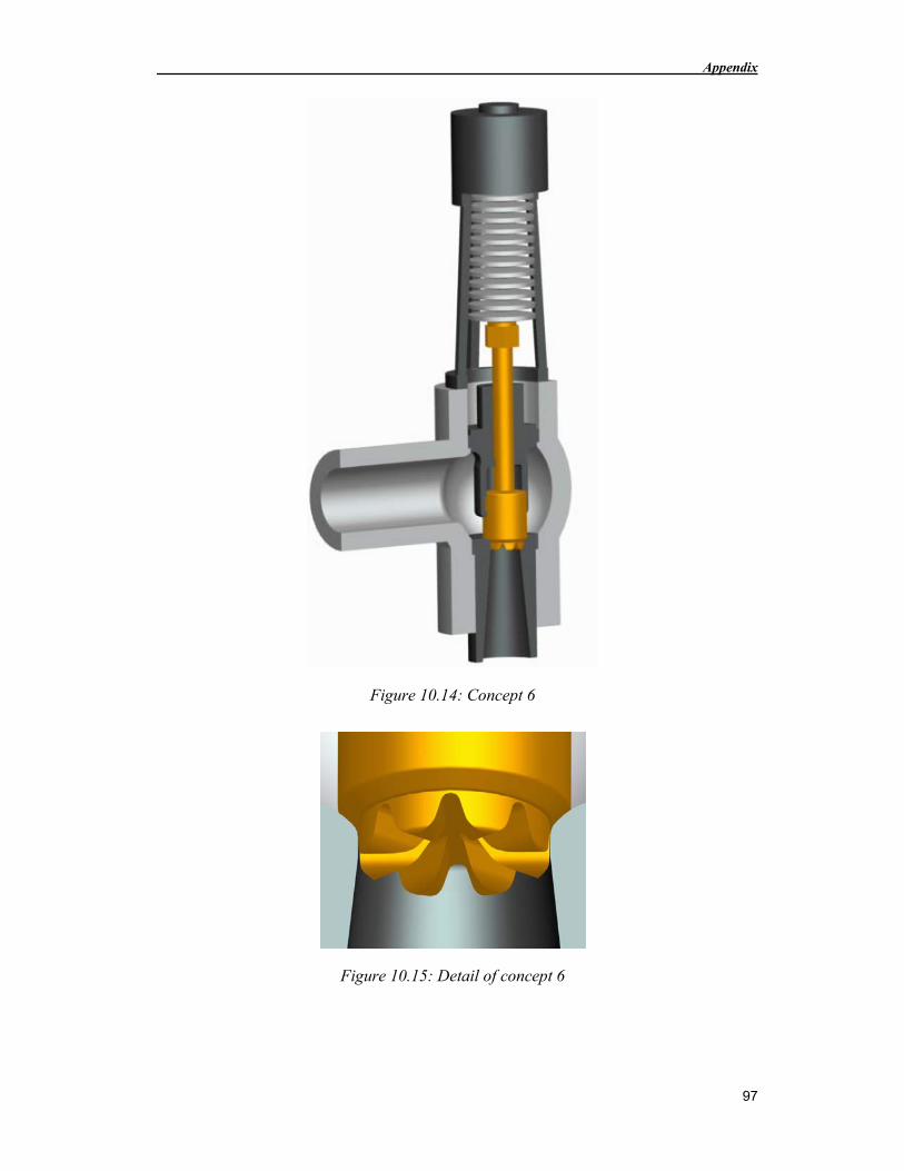
Appendix
97
Figure 10.14: Concept 6
Figure 10.15: Detail of concept 6
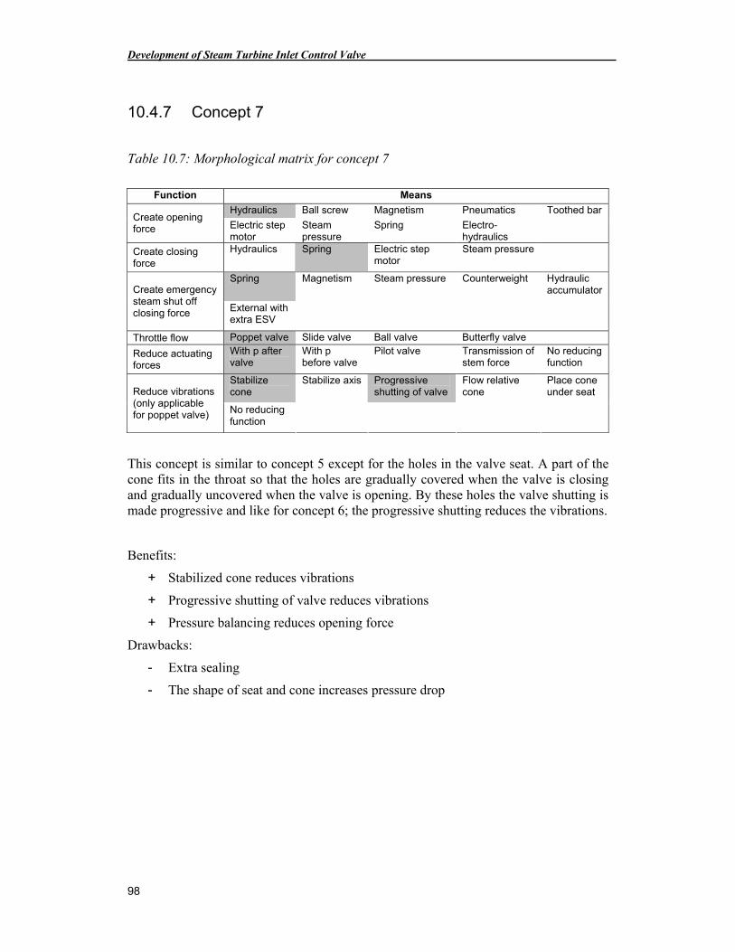
Development of Steam Turbine Inlet Control Valve
98
10.4.7 Concept 7
Table 10.7: Morphological matrix for concept 7
Function Means
Hydraulics Ball screw Magnetism Pneumatics Toothed bar Create opening force Electric step
motor Steam pressure
Spring Electro-hydraulics
Create closing force
Hydraulics Spring Electric step motor
Steam pressure
Spring Magnetism Steam pressure Counterweight Hydraulic accumulator Create emergency
steam shut off closing force External with
extra ESV
Throttle flow Poppet valve Slide valve Ball valve Butterfly valve
Reduce actuating forces
With p after valve
With p before valve
Pilot valve Transmission of stem force
No reducing function
Stabilize cone
Stabilize axis Progressive shutting of valve
Flow relative cone
Place cone under seat Reduce vibrations
(only applicable for poppet valve) No reducing
function
This concept is similar to concept 5 except for the holes in the valve seat. A part of the cone fits in the throat so that the holes are gradually covered when the valve is closing and gradually uncovered when the valve is opening. By these holes the valve shutting is made progressive and like for concept 6; the progressive shutting reduces the vibrations.
Benefits:
+ Stabilized cone reduces vibrations
+ Progressive shutting of valve reduces vibrations
+ Pressure balancing reduces opening force
Drawbacks:
- Extra sealing
- The shape of seat and cone increases pressure drop
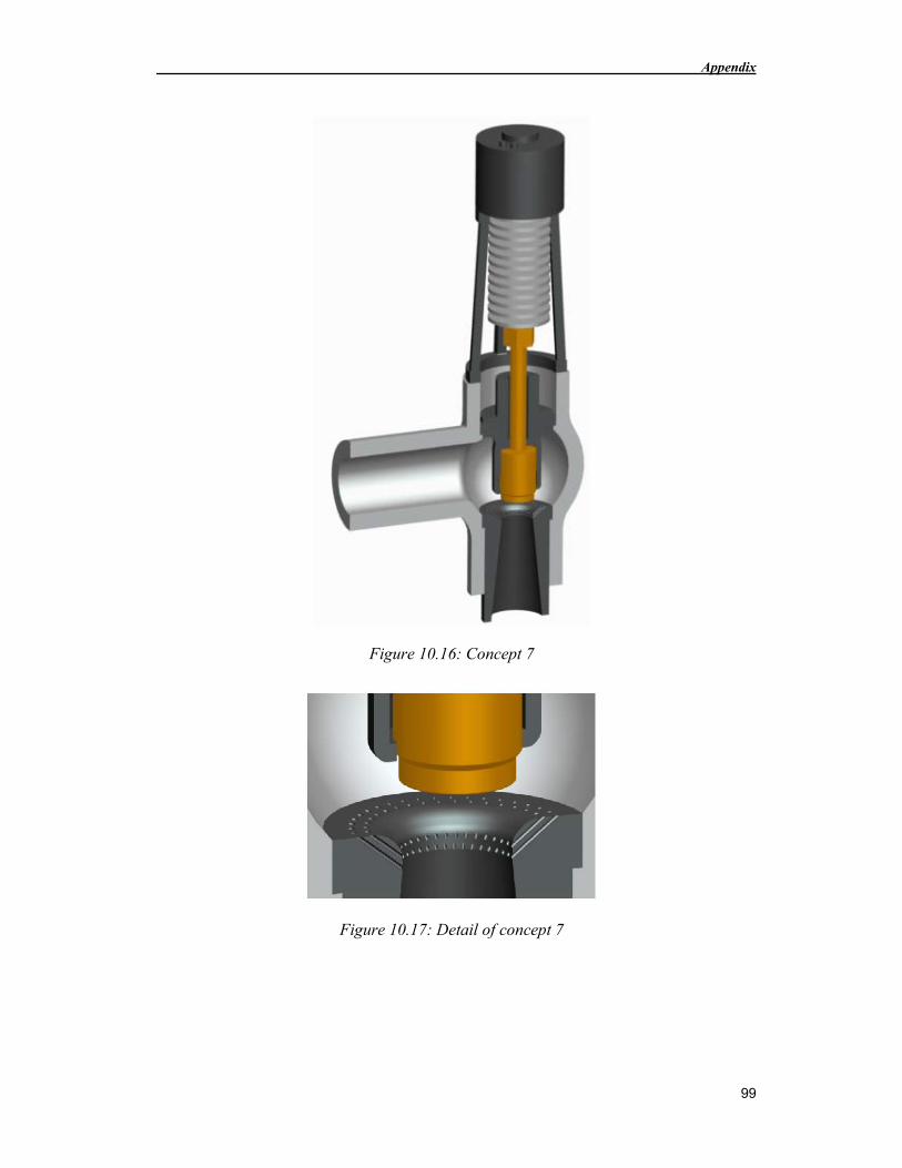
Appendix
99
Figure 10.16: Concept 7
Figure 10.17: Detail of concept 7
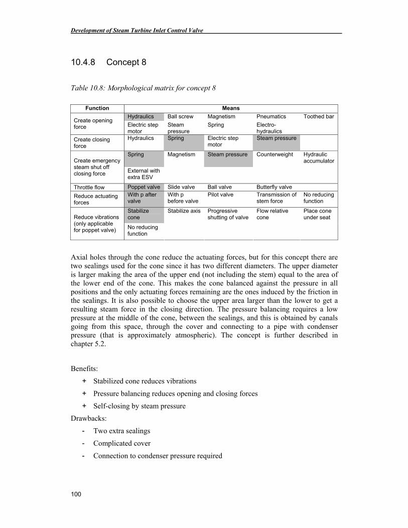
Development of Steam Turbine Inlet Control Valve
100
10.4.8 Concept 8
Table 10.8: Morphological matrix for concept 8
Function Means
Hydraulics Ball screw Magnetism Pneumatics Toothed bar Create opening force Electric step
motor Steam pressure
Spring Electro-hydraulics
Create closing force
Hydraulics Spring Electric step motor
Steam pressure
Spring Magnetism Steam pressure Counterweight Hydraulic accumulator Create emergency
steam shut off closing force External with
extra ESV
Throttle flow Poppet valve Slide valve Ball valve Butterfly valve
Reduce actuating forces
With p after valve
With p before valve
Pilot valve Transmission of stem force
No reducing function
Stabilize cone
Stabilize axis Progressive shutting of valve
Flow relative cone
Place cone under seat Reduce vibrations
(only applicable for poppet valve) No reducing
function
Axial holes through the cone reduce the actuating forces, but for this concept there are two sealings used for the cone since it has two different diameters. The upper diameter is larger making the area of the upper end (not including the stem) equal to the area of the lower end of the cone. This makes the cone balanced against the pressure in all positions and the only actuating forces remaining are the ones induced by the friction in the sealings. It is also possible to choose the upper area larger than the lower to get a resulting steam force in the closing direction. The pressure balancing requires a low pressure at the middle of the cone, between the sealings, and this is obtained by canals going from this space, through the cover and connecting to a pipe with condenser pressure (that is approximately atmospheric). The concept is further described in chapter 5.2.
Benefits:
+ Stabilized cone reduces vibrations
+ Pressure balancing reduces opening and closing forces
+ Self-closing by steam pressure
Drawbacks:
- Two extra sealings
- Complicated cover
- Connection to condenser pressure required
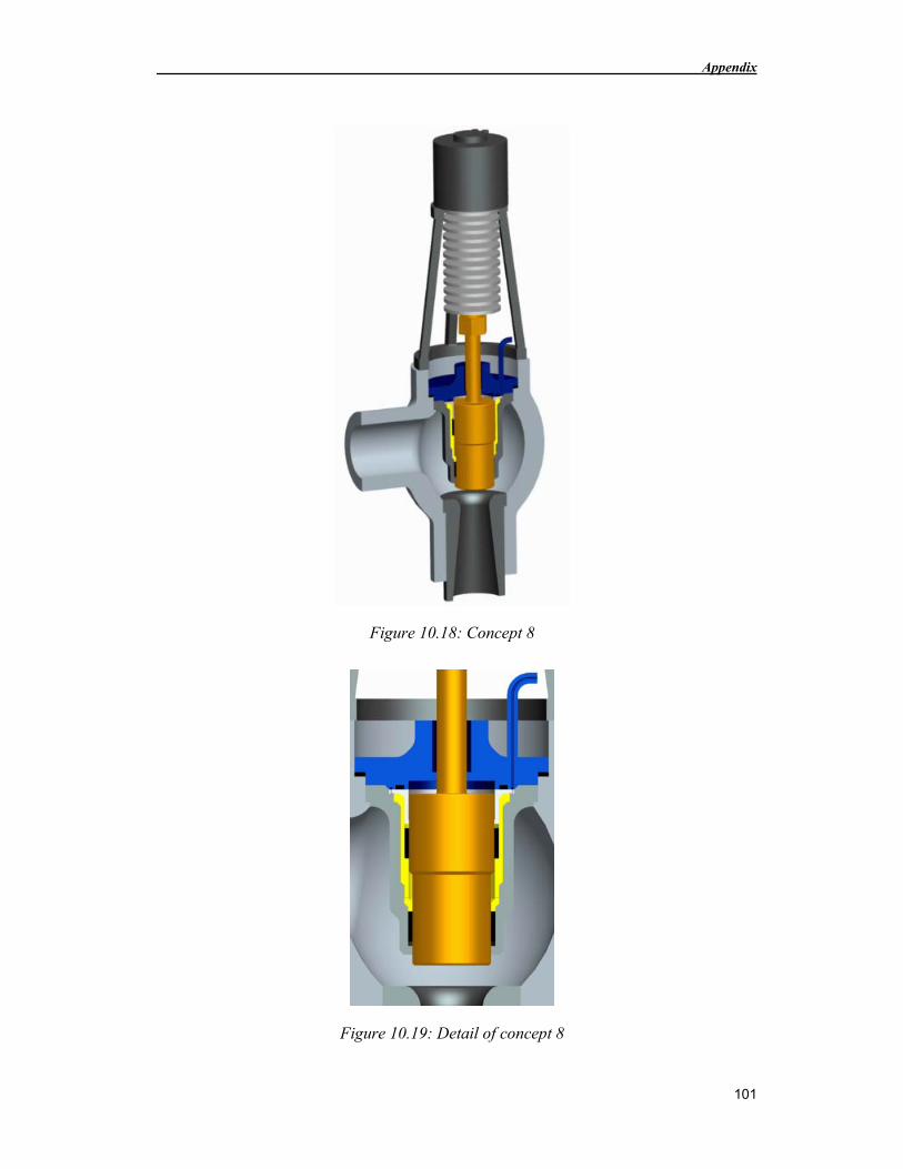
Appendix
101
Figure 10.18: Concept 8
Figure 10.19: Detail of concept 8
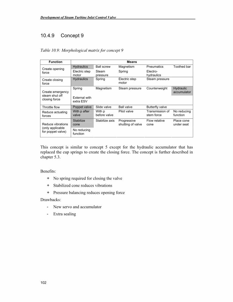
Development of Steam Turbine Inlet Control Valve
102
10.4.9 Concept 9
Table 10.9: Morphological matrix for concept 9
Function Means
Hydraulics Ball screw Magnetism Pneumatics Toothed bar Create opening force Electric step
motor Steam pressure
Spring Electro-hydraulics
Create closing force
Hydraulics Spring Electric step motor
Steam pressure
Spring Magnetism Steam pressure Counterweight Hydraulic accumulator Create emergency
steam shut off closing force External with
extra ESV
Throttle flow Poppet valve Slide valve Ball valve Butterfly valve
Reduce actuating forces
With p after valve
With p before valve
Pilot valve Transmission of stem force
No reducing function
Stabilize cone
Stabilize axis Progressive shutting of valve
Flow relative cone
Place cone under seat Reduce vibrations
(only applicable for poppet valve) No reducing
function
This concept is similar to concept 5 except for the hydraulic accumulator that has replaced the cup springs to create the closing force. The concept is further described in chapter 5.3.
Benefits:
+ No spring required for closing the valve
+ Stabilized cone reduces vibrations
+ Pressure balancing reduces opening force
Drawbacks:
- New servo and accumulator
- Extra sealing
Appendix
103
Figure 10.20: Concept 9
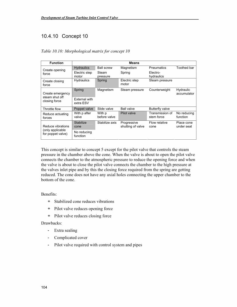
Development of Steam Turbine Inlet Control Valve
104
10.4.10 Concept 10
Table 10.10: Morphological matrix for concept 10
Function Means
Hydraulics Ball screw Magnetism Pneumatics Toothed bar Create opening force Electric step
motor Steam pressure
Spring Electro-hydraulics
Create closing force
Hydraulics Spring Electric step motor
Steam pressure
Spring Magnetism Steam pressure Counterweight Hydraulic accumulator Create emergency
steam shut off closing force External with
extra ESV
Throttle flow Poppet valve Slide valve Ball valve Butterfly valve
Reduce actuating forces
With p after valve
With p before valve
Pilot valve Transmission of stem force
No reducing function
Stabilize cone
Stabilize axis Progressive shutting of valve
Flow relative cone
Place cone under seat Reduce vibrations
(only applicable for poppet valve) No reducing
function
This concept is similar to concept 5 except for the pilot valve that controls the steam pressure in the chamber above the cone. When the valve is about to open the pilot valve connects the chamber to the atmospheric pressure to reduce the opening force and when the valve is about to close the pilot valve connects the chamber to the high pressure at the valves inlet pipe and by this the closing force required from the spring are getting reduced. The cone does not have any axial holes connecting the upper chamber to the bottom of the cone.
Benefits:
+ Stabilized cone reduces vibrations
+ Pilot valve reduces opening force
+ Pilot valve reduces closing force
Drawbacks:
- Extra sealing
- Complicated cover
- Pilot valve required with control system and pipes
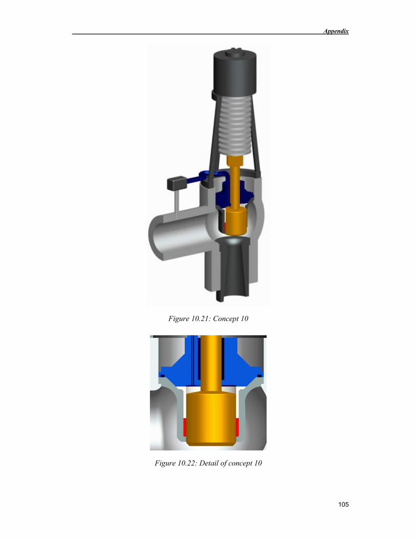
Appendix
105
Figure 10.21: Concept 10
Figure 10.22: Detail of concept 10
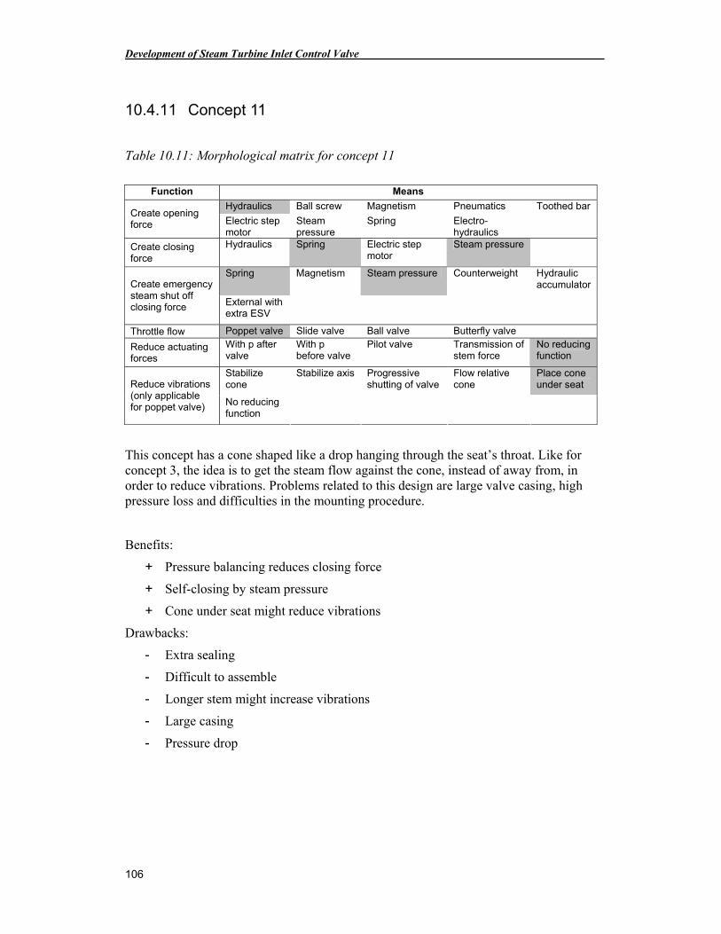
Development of Steam Turbine Inlet Control Valve
106
10.4.11 Concept 11
Table 10.11: Morphological matrix for concept 11
Function Means
Hydraulics Ball screw Magnetism Pneumatics Toothed bar Create opening force Electric step
motor Steam pressure
Spring Electro-hydraulics
Create closing force
Hydraulics Spring Electric step motor
Steam pressure
Spring Magnetism Steam pressure Counterweight Hydraulic accumulator Create emergency
steam shut off closing force External with
extra ESV
Throttle flow Poppet valve Slide valve Ball valve Butterfly valve
Reduce actuating forces
With p after valve
With p before valve
Pilot valve Transmission of stem force
No reducing function
Stabilize cone
Stabilize axis Progressive shutting of valve
Flow relative cone
Place cone under seat Reduce vibrations
(only applicable for poppet valve) No reducing
function
This concept has a cone shaped like a drop hanging through the seat’s throat. Like for concept 3, the idea is to get the steam flow against the cone, instead of away from, in order to reduce vibrations. Problems related to this design are large valve casing, high pressure loss and difficulties in the mounting procedure.
Benefits:
+ Pressure balancing reduces closing force
+ Self-closing by steam pressure
+ Cone under seat might reduce vibrations
Drawbacks:
- Extra sealing
- Difficult to assemble
- Longer stem might increase vibrations
- Large casing
- Pressure drop
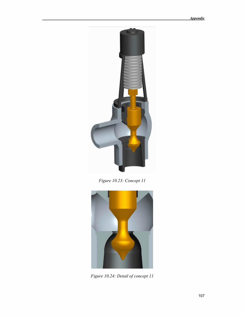
Appendix
107
Figure 10.23: Concept 11
Figure 10.24: Detail of concept 11
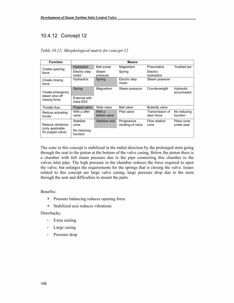
Development of Steam Turbine Inlet Control Valve
108
10.4.12 Concept 12
Table 10.12: Morphological matrix for concept 12
Function Means
Hydraulics Ball screw Magnetism Pneumatics Toothed bar Create opening force Electric step
motor Steam pressure
Spring Electro-hydraulics
Create closing force
Hydraulics Spring Electric step motor
Steam pressure
Spring Magnetism Steam pressure Counterweight Hydraulic accumulator Create emergency
steam shut off closing force External with
extra ESV
Throttle flow Poppet valve Slide valve Ball valve Butterfly valve
Reduce actuating forces
With p after valve
With p before valve
Pilot valve Transmission of stem force
No reducing function
Stabilize cone
Stabilize axis Progressive shutting of valve
Flow relative cone
Place cone under seat Reduce vibrations
(only applicable for poppet valve) No reducing
function
The cone in this concept is stabilized in the radial direction by the prolonged stem going through the seat to the piston at the bottom of the valve casing. Below the piston there is a chamber with full steam pressure due to the pipe connecting this chamber to the valves inlet pipe. The high pressure in the chamber reduces the force required to open the valve, but enlarges the requirements for the springs that is closing the valve. Issues related to this concept are large valve casing, large pressure drop due to the stem through the seat and difficulties to mount the parts.
Benefits:
+ Pressure balancing reduces opening force
+ Stabilized axis reduces vibrations
Drawbacks:
- Extra sealing
- Large casing
- Pressure drop
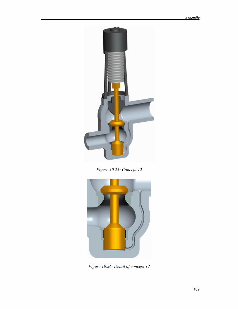
Appendix
109
Figure 10.25: Concept 12
Figure 10.26: Detail of concept 12
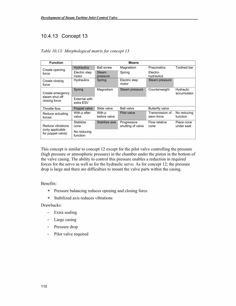
Development of Steam Turbine Inlet Control Valve
110
10.4.13 Concept 13
Table 10.13: Morphological matrix for concept 13
Function Means
Hydraulics Ball screw Magnetism Pneumatics Toothed bar Create opening force Electric step
motor Steam pressure
Spring Electro-hydraulics
Create closing force
Hydraulics Spring Electric step motor
Steam pressure
Spring Magnetism Steam pressure Counterweight Hydraulic accumulator Create emergency
steam shut off closing force External with
extra ESV
Throttle flow Poppet valve Slide valve Ball valve Butterfly valve
Reduce actuating forces
With p after valve
With p before valve
Pilot valve Transmission of stem force
No reducing function
Stabilize cone
Stabilize axis Progressive shutting of valve
Flow relative cone
Place cone under seat Reduce vibrations
(only applicable for poppet valve) No reducing
function
This concept is similar to concept 12 except for the pilot valve controlling the pressure (high pressure or atmospheric pressure) in the chamber under the piston in the bottom of the valve casing. The ability to control this pressure enables a reduction in required forces for the servo as well as for the hydraulic servo. As for concept 12; the pressure drop is large and there are difficulties to mount the valve parts within the casing.
Benefits:
+ Pressure balancing reduces opening and closing force
+ Stabilized axis reduces vibrations
Drawbacks:
- Extra sealing
- Large casing
- Pressure drop
- Pilot valve required
Appendix
111
Figure 10.27: Concept 13
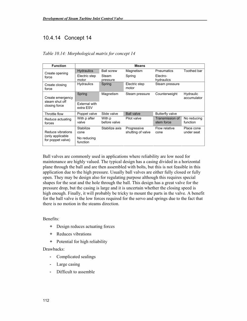
Development of Steam Turbine Inlet Control Valve
112
10.4.14 Concept 14
Table 10.14: Morphological matrix for concept 14
Function Means
Hydraulics Ball screw Magnetism Pneumatics Toothed bar Create opening force Electric step
motor Steam pressure
Spring Electro-hydraulics
Create closing force
Hydraulics Spring Electric step motor
Steam pressure
Spring Magnetism Steam pressure Counterweight Hydraulic accumulator Create emergency
steam shut off closing force External with
extra ESV
Throttle flow Poppet valve Slide valve Ball valve Butterfly valve
Reduce actuating forces
With p after valve
With p before valve
Pilot valve Transmission of stem force
No reducing function
Stabilize cone
Stabilize axis Progressive shutting of valve
Flow relative cone
Place cone under seat Reduce vibrations
(only applicable for poppet valve) No reducing
function
Ball valves are commonly used in applications where reliability are low need for maintenance are highly valued. The typical design has a casing divided in a horizontal plane through the ball and are then assembled with bolts, but this is not feasible in this application due to the high pressure. Usually ball valves are either fully closed or fully open. They may be design also for regulating purpose although this requires special shapes for the seat and the hole through the ball. This design has a great valve for the pressure drop, but the casing is large and it is uncertain whether the closing speed is high enough. Finally, it will probably be tricky to mount the parts in the valve. A benefit for the ball valve is the low forces required for the servo and springs due to the fact that there is no motion in the steams direction.
Benefits:
+ Design reduces actuating forces
+ Reduces vibrations
+ Potential for high reliability
Drawbacks:
- Complicated sealings
- Large casing
- Difficult to assemble
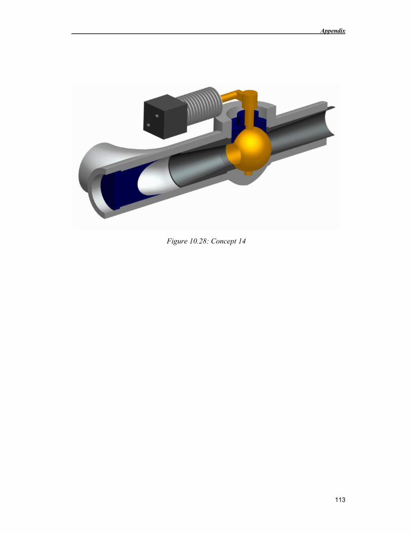
Appendix
113
Figure 10.28: Concept 14
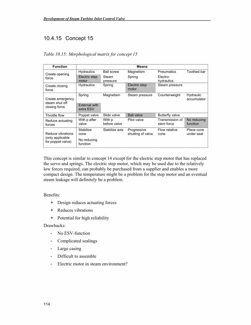
Development of Steam Turbine Inlet Control Valve
114
10.4.15 Concept 15
Table 10.15: Morphological matrix for concept 15
Function Means
Hydraulics Ball screw Magnetism Pneumatics Toothed bar Create opening force Electric step
motor Steam pressure
Spring Electro-hydraulics
Create closing force
Hydraulics Spring Electric step motor
Steam pressure
Spring Magnetism Steam pressure Counterweight Hydraulic accumulator Create emergency
steam shut off closing force External with
extra ESV
Throttle flow Poppet valve Slide valve Ball valve Butterfly valve
Reduce actuating forces
With p after valve
With p before valve
Pilot valve Transmission of stem force
No reducing function
Stabilize cone
Stabilize axis Progressive shutting of valve
Flow relative cone
Place cone under seat Reduce vibrations
(only applicable for poppet valve) No reducing
function
This concept is similar to concept 14 except for the electric step motor that has replaced the servo and springs. The electric step motor, which may be used due to the relatively low forces required, can probably be purchased from a supplier and enables a more compact design. The temperature might be a problem for the step motor and an eventual steam leakage will definitely be a problem.
Benefits:
+ Design reduces actuating forces
+ Reduces vibrations
+ Potential for high reliability
Drawbacks:
- No ESV-function
- Complicated sealings
- Large casing
- Difficult to assemble
- Electric motor in steam environment?
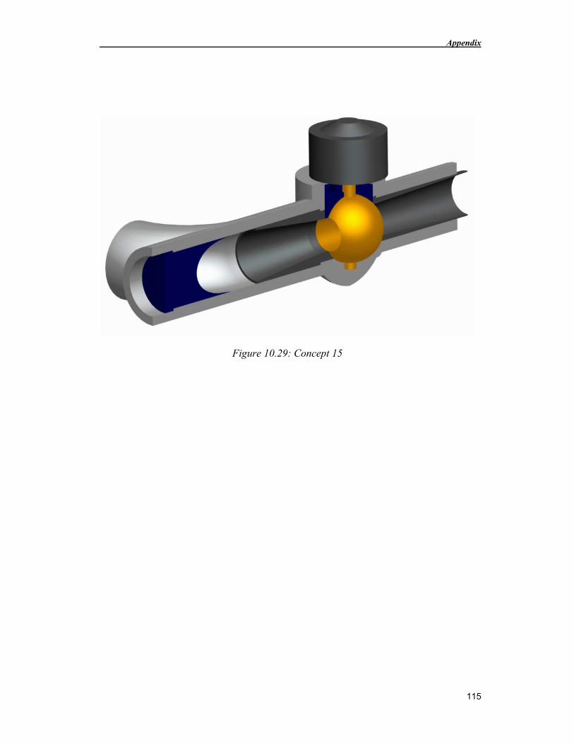
Appendix
115
Figure 10.29: Concept 15
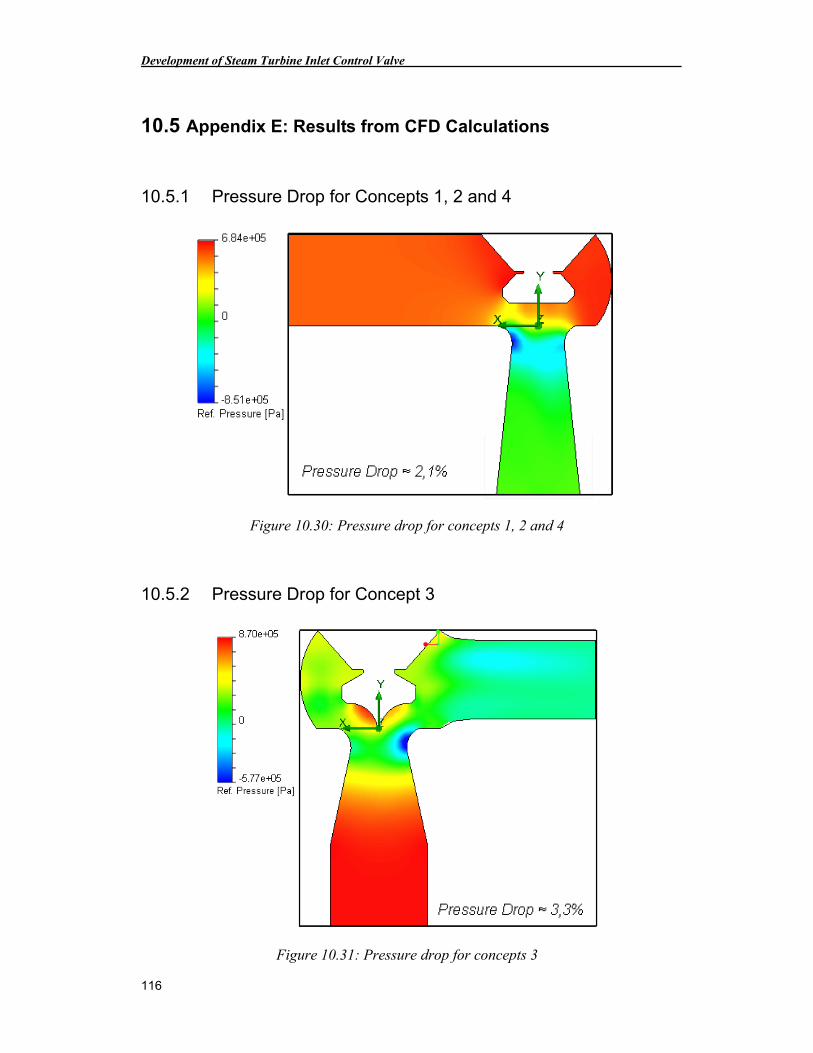
Development of Steam Turbine Inlet Control Valve
116
10.5 Appendix E: Results from CFD Calculations
10.5.1 Pressure Drop for Concepts 1, 2 and 4
Figure 10.30: Pressure drop for concepts 1, 2 and 4
10.5.2 Pressure Drop for Concept 3
Figure 10.31: Pressure drop for concepts 3
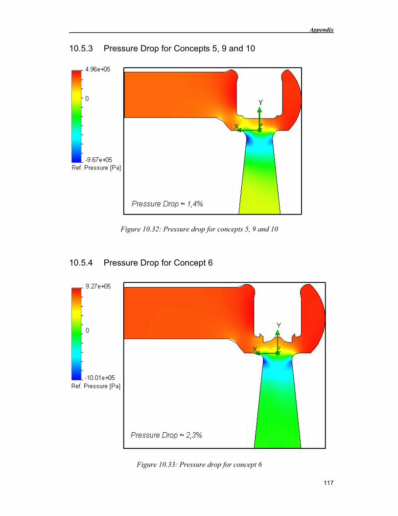
Appendix
117
10.5.3 Pressure Drop for Concepts 5, 9 and 10
Figure 10.32: Pressure drop for concepts 5, 9 and 10
10.5.4 Pressure Drop for Concept 6
Figure 10.33: Pressure drop for concept 6
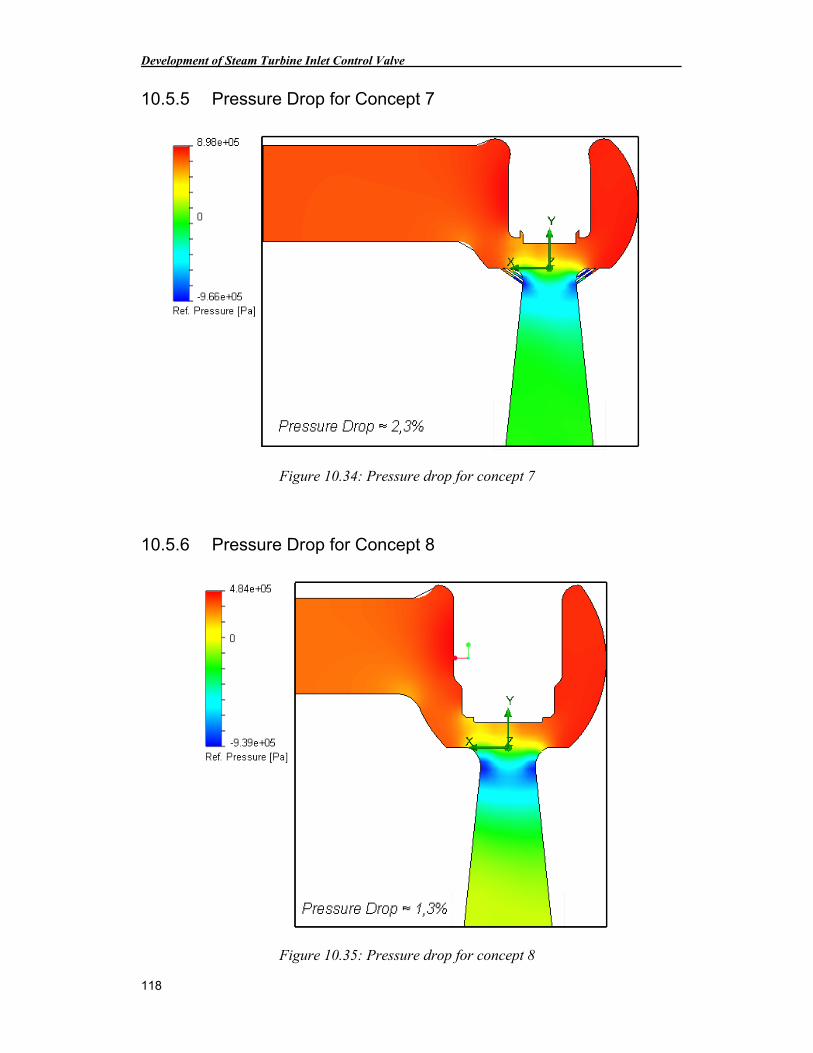
Development of Steam Turbine Inlet Control Valve
118
10.5.5 Pressure Drop for Concept 7
Figure 10.34: Pressure drop for concept 7
10.5.6 Pressure Drop for Concept 8
Figure 10.35: Pressure drop for concept 8
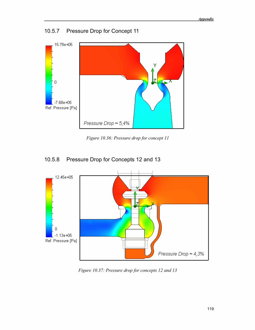
Appendix
119
10.5.7 Pressure Drop for Concept 11
Figure 10.36: Pressure drop for concept 11
10.5.8 Pressure Drop for Concepts 12 and 13
Figure 10.37: Pressure drop for concepts 12 and 13
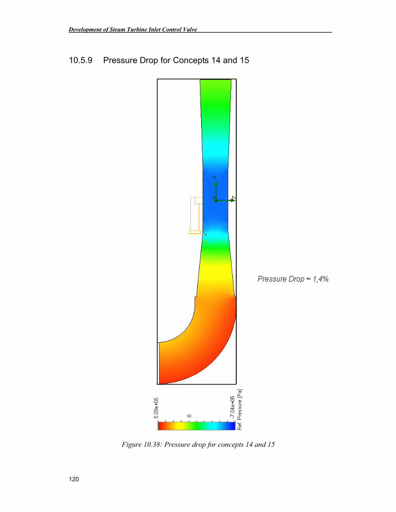
Development of Steam Turbine Inlet Control Valve
120
10.5.9 Pressure Drop for Concepts 14 and 15
Figure 10.38: Pressure drop for concepts 14 and 15