Embed Size (px)
Citation preview

Dep
artm
ent
of T
echn
olog
y, M
athe
mat
ics
and
Com
pute
r Sci
ence
EXAMENSARBETE 2004:M019
Veronica Fohlén Anneli Johansson
Development of Squeak and Rattle Design Guidelines for the Instrument Panel Area
Summary The aim of this report is to describe the development of design guidelines for squeak and rattle to Saab Automobile. The Design Guidelines are limited to the instrument panel. It contains design examples from Saab 95, Saab 93 Sport Sedan, BMW 325 convertible, Opel Vectra and Volvo V70. A pilot study was done before this thesis by the same authors and is the basic source for the Design Guidelines.
The Design Guidelines is divided in three sections: General Recommendations, Materials and Design Examples. In the Design Examples, different attachment methods are analysed and the conclusions are the basis for the recommendations. The other section, which is about materials, contains advise for choosing materials, data of different plastic materials and explanation of the terms stick slip and rattle.
To avoid problems with squeak and rattle, the parts must be sufficiently attached so that no relative motion can occur. The stiffness of the attachment area is an important parameter to consider. High stiffness gives high first resonant frequency and avoids resonance with the major engine idle frequencies and road excitation, which is good for preventing squeak and rattle.
Screw joint is the preferable attachment method for high-weight parts. Snap fit is usually a well functioning method for low-weight parts.
To find the source of the squeak and rattle problem the entire design concept must be considered.
Publisher: University of Trollhättan/Uddevalla, Department of Technology Box 957, S-461 29 Trollhättan, SWEDEN Phone: + 46 520 47 50 00 Fax: + 46 520 47 50 99 E-mail: [email protected]
Examiner: Jan-Inge Johansson Advisor: Stefan Wimnell, Saab Automobile AB Subject: Mechanical Engineering Language: English Level: Advanced Credits: 10 Swedish, 15 ECTS credits Number: 2004:M019 Date: Mars 30, 2004 Keywords Squeak, Rattle, Guidelines, Instrument Panel, Stick-slip

Development of Squeak and Rattle Design Guidelines for the Instrument Panel Area
Preface The Squeak and Rattle Design Guidelines is available at Saab Automobile’s intranet. Due to the confidential nature of the subject only selected parts of the actual Design Guidelines are included in this report.
During the work with the Design Guidelines we had great support from Richard Karlsson and Tomas Stigsson at the Noise and Vibration Centre at Saab Automobile in Trollhättan. We are very grateful for all their help and time. We also want to thank our supervisors Claes Fredriksson at the University of Trollhättan/Uddevalla and Stefan Wimnell at Saab Automobile.
Trollhättan, Mars 2004
Veronica Fohlén and Anneli Johansson
Development of Squeak and Rattle Design Guidelines for the Instrument Panel Area
Contents
Summary ........................................................................................................................ ii Preface ............................................................................................................................. iii 1 Introduction...................................................................................................................1 2 Methodology.................................................................................................................2
2.1 Definitions..............................................................................................................2 2.2 Pilot study ..............................................................................................................4 2.3 Sources of Information ..........................................................................................4
3 Results and Discussion .................................................................................................5 3.1 Materials................................................................................................................5 3.2 Illustration Examples of Attachment Methods.......................................................8 3.3 What to Consider When Designing an Instrument Panel Carrier.......................20 3.4 The effect of tolerances........................................................................................21 3.5 What to Consider with Snap Fit Attachment .......................................................22 3.6 What to Consider with Screw Joint Attachment ..................................................24 3.7 Recommendations ................................................................................................26
4 Summary and Conclusions .........................................................................................27 5 Future Work................................................................................................................28 6 References...................................................................................................................29

Development of Squeak and Rattle Design Guidelines for the Instrument Panel Area
Development of Squeak and Rattle Design Guidelines for the Instrument Panel Area
1
1 Introduction The cars of today become more and more silent running. Interior noise that the driver would not notice in an older car becomes more obvious in new models. Only interior sounds that give information about the function of the car are desired. Squeaks and rattles due to badly attached details are annoying to the driver and have a negative influence on the quality impression. It may also have a distractive effect on the driver and result in lost concentration. This may affect the driving and may be a safety risk in the traffic.
It is important to prevent possible squeak and rattle sources early in the design phase. The cost of changes increases during the design process. Temporary “fix solutions”, e.g., felt tapes are expensive and should not be seen as a solution for squeak and rattle problems.
During the design of the attachment methods there are many parameters to consider. To facilitate the design work, Saab Automobile wishes to have design guidelines for squeak and rattle. In addition to being rigid, attached parts should also be quick and easy to assemble. The mounting process should not cause ergonomic problems for the car assembler. The design guidelines are limited to the instrument panel. It contains design examples from Saab 95, Saab 93 Sport Sedan, BMW 325 convertible, Opel Vectra and Volvo V70.
The aim of the design guidelines is to provide needed information. To obtain a clear structure, the guidelines are divided in three sections: General recommendations, Material and Design Examples. In General recommendations, the user can find information on what to consider when designing attachment methods with screw joints or snap fits. The user can also read about General Motor’s four main principles of avoiding squeaks and rattles. In the Material section, information can be found about different polymers and their characteristics. There is also information on how surrounding conditions like temperature affect the plastic construction and material compatibility with regard to squeak and rattle behaviour. Finally, in the Design Examples, illustration examples are shown and different attachment methods are analysed.
Development of Squeak and Rattle Design Guidelines for the Instrument Panel Area
2
2 Methodology
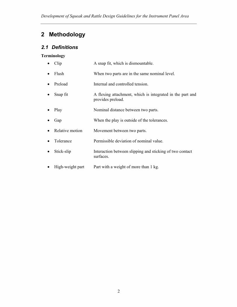
2.1 Definitions Terminology
• Clip A snap fit, which is dismountable.
• Flush When two parts are in the same nominal level. • Preload Internal and controlled tension.
• Snap fit A flexing attachment, which is integrated in the part and
provides preload.
• Play Nominal distance between two parts.
• Gap When the play is outside of the tolerances.
• Relative motion Movement between two parts.
• Tolerance Permissible deviation of nominal value.
• Stick-slip Interaction between slipping and sticking of two contact surfaces.
• High-weight part Part with a weight of more than 1 kg.
Development of Squeak and Rattle Design Guidelines for the Instrument Panel Area
3
Main Coordinate System
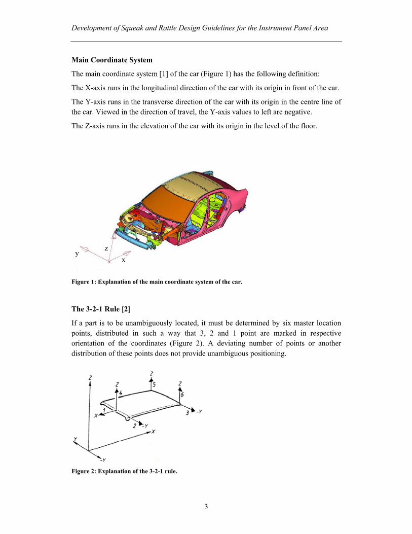
The main coordinate system [1] of the car (Figure 1) has the following definition:
The X-axis runs in the longitudinal direction of the car with its origin in front of the car.
The Y-axis runs in the transverse direction of the car with its origin in the centre line of the car. Viewed in the direction of travel, the Y-axis values to left are negative.
The Z-axis runs in the elevation of the car with its origin in the level of the floor.
Figure 1: Explanation of the main coordinate system of the car.
The 3-2-1 Rule [2]
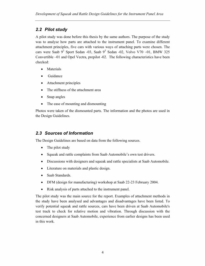
If a part is to be unambiguously located, it must be determined by six master location points, distributed in such a way that 3, 2 and 1 point are marked in respective orientation of the coordinates (Figure 2). A deviating number of points or another distribution of these points does not provide unambiguous positioning.
Figure 2: Explanation of the 3-2-1 rule.
y z
x
Development of Squeak and Rattle Design Guidelines for the Instrument Panel Area
4
2.2 Pilot study A pilot study was done before this thesis by the same authors. The purpose of the study was to analyse how parts are attached to the instrument panel. To examine different attachment principles, five cars with various ways of attaching parts were chosen. The cars were Saab 93 Sport Sedan -03, Saab 95 Sedan -02, Volvo V70 –01, BMW 325 Convertible –01 and Opel Vectra, prepilot -02. The following characteristics have been checked:
• Materials
• Guidance
• Attachment principles
• The stiffness of the attachment area
• Snap angles
• The ease of mounting and dismounting
Photos were taken of the dismounted parts. The information and the photos are used in the Design Guidelines.
2.3 Sources of Information The Design Guidelines are based on data from the following sources.
• The pilot study
• Squeak and rattle complaints from Saab Automobile’s own test drivers.
• Discussions with designers and squeak and rattle specialists at Saab Automobile.
• Literature on materials and plastic design.
• Saab Standards.
• DFM (design for manufacturing) workshop at Saab 22-23 February 2004.
• Risk analysis of parts attached to the instrument panel.
The pilot study was the main source for the report. Examples of attachment methods in the study have been analysed and advantages and disadvantages have been listed. To verify potential squeak and rattle sources, cars have been driven at Saab Automobile's test track to check for relative motion and vibration. Through discussion with the concerned designers at Saab Automobile, experience from earlier designs has been used in this work.
Development of Squeak and Rattle Design Guidelines for the Instrument Panel Area
5
3 Results and Discussion
3.1 Materials The material of the parts has an influence on the properties for squeak and rattle. Some materials are not compatible with each other due to they may have high tendency for stick-slip. Paint and coating on the parts may result in other surface properties for the material.
Material Choice Material compatibility, temperature, forces, loads and relative motion are examples of parameters that must be included in the choice of material for the parts [3]. Constructions without clearance between the parts should have materials, which are compatible with each other or have isolation, to avoid squeak due to relative motion. Many of the parts in the instrument panel are exposed to high temperatures and, therefore, the materials should have suitable temperature properties. The material must be dimensioned for the loads to avoid relaxation of the attachment joint.
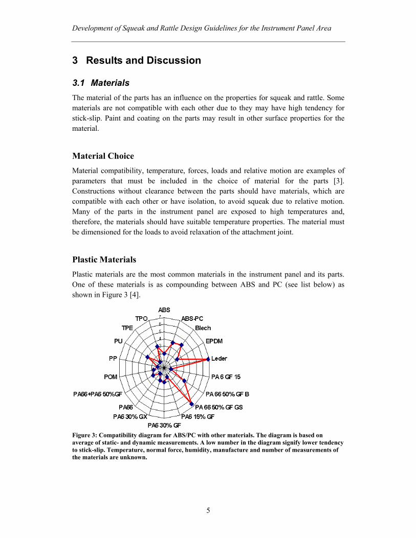
Plastic Materials Plastic materials are the most common materials in the instrument panel and its parts. One of these materials is as compounding between ABS and PC (see list below) as shown in Figure 3 [4].
Figure 3: Compatibility diagram for ABS/PC with other materials. The diagram is based on average of static- and dynamic measurements. A low number in the diagram signify lower tendency to stick-slip. Temperature, normal force, humidity, manufacture and number of measurements of the materials are unknown.

Development of Squeak and Rattle Design Guidelines for the Instrument Panel Area
6
Polymers are affected differently at high and low temperatures. At high temperature the material expand and the clearance between different parts may decrease. This may result in stick-slip, due to the relative motion that occurs. Low temperatures make the material hard and brittle, which may cause rattle.
Thermoplastic materials may be divided in two groups: amorphous and crystalline [5] [6].
Amorphous Thermoplastic
Characteristics of amorphous thermoplastic:
• High stiffness
• Brittleness
• High friction
• Low resistance against solvents
• Limited abrasive resistance
Some common amorphous thermoplastics in the instrument panel are listed below [5] [6]:
ABS–Acrylonitrile-Butadiene-Styrene
ABS has high impact strength, surface hardness and surface finish. The plastic is heat resisting but may be decomposed by UV-radiation. ABS has moderate frictional and abrasion properties [7].
PC–Polycarbonate
PC has high impact strength and stiffness but low scratch resistance. The material has high creep resistance even at high temperatures. PC is heat resisting but may be decomposed by UV-radiation. The material has relativity high friction and limited resistance to abrasion (poorer than, for instance, PA and POM). Most types of PC have satisfactory resistance to abrasion at low loads [7].
SMA–Styrene Maleic Anhydride
SMA is based on styrene and reinforced with about 20% glass fibre. The material is brittle. SMA against SMA or other plastic materials often result in stick-slip and the material amplified the generated sounds.
Crystalline Thermoplastic
Characteristics of crystalline thermoplastic:
• Low friction and high abrasive resistance
• High resistance against chemicals
• Higher tensional stiffness than amorphous thermoplastics.
Development of Squeak and Rattle Design Guidelines for the Instrument Panel Area
7
Some common crystalline thermoplastics in the instrument are listed below:
PA–Polyamide
PA has a good combination of mechanical and chemical properties. All types of polyamide emit or absorb humidity. The humidity causes lower tensile strength, stiffness, resistance against creep and higher impact strength. The material expands due to the humidity, which should be considered during the design of parts with close tolerances. PA becomes decomposed by UV-radiation. The material has low coefficient of friction (higher than POM) and very good resistance to abrasion [7].
POM–Polyoxymethylene
POM has a good combination of strength, stiffness, fatigue strength and creep resistance. The material is sensitive to break points. POM has good resistance against humidity and chemicals. The material has a lower coefficient of friction than PA and the abrasion properties are comparable to PA [7].
PP–Polypropylene
PP has high fatigue strength but become brittle below 0°C. The material has low scratch resistance and becomes decomposed by UV-radiation.
Thermoplastic Elastomer
Thermoplastic elastomers are materials, which are comparable to compare to plastic, and rubber.
TPO–Thermoplastic Olefin
TPO is based on alloys of ethylene plastic or propylene plastic with EPDM-rubber. The material has high mechanical strength and is elastic. Operating temperature is about -40°C to 100°C.
Stick-slip The condition for squeak is movement between two contacting surfaces. The friction forces [3], which occur between contacting surfaces, may cause elastic deformation of components adjacent to the contacting surfaces. The elastic deformation is a mechanism for storing energy. When the energy is released noise may occur. This noise is a squeak (multiple stick slips) or a tick (single stick slip). The release of the stored elastic energy may occur when the kinetic friction is less than the static friction. The difference between the static and the kinetic friction increase with the time of contact before sliding is initiated for some polymers. The creeping during static contact increases the area of contact and the static friction will increase for most polymers.
Development of Squeak and Rattle Design Guidelines for the Instrument Panel Area
8
The use of amorphous thermoplastic such as PC increases the potential for squeaks compared to crystalline thermoplastic [8]. Humidity, normal force, system stiffness and temperature are examples of other parameters that may affect the squeak potential. The size of the contact area does not affect the properties of squeak, however, it does affect the static friction.
Graining of a surface e.g. ABS may reduce the properties of stick-slip when the surface is in contact with a porous material e.g., EPP. A firm material against polymer with graining has a very small influence on the stick-slip properties, but the static friction will be changed.
Rattle Rattle occurs when two parts, which have a gap between each other, start to vibrate and pound against each other due to the relative motion. The vibrations may also cause high abrasion on the parts, surface damage and fatigue failure.
3.2 Illustration Examples of Attachment Methods In the pilot study, parts of the instrument panel were demounted and the attachment methods were documented. This information has been used during the work of making the Design Guidelines. The attachment methods have been analysed and the conclusions are the basis for the recommendations.
The examples in the Design Guidelines are divided in four categories. The categories are:
1. Instrument panel attachment options.
2. Attachment of high-weight parts.
a. Screw joint attachments.
b. Alternative attachment methods.
3. Snap-fit attachment of low- weight parts.
4. Air outlets.
Due to the confidential nature of the subject, only one selected example of each group is shown in this report. The parts in the examples have been chosen due to their suitability for illustrating the recommendations.
Instrument Panel Attachment Options The attachment options of parts in the instrument panel depend on several parameters. The main factor is the design concept of the instrument panel. The design limits the attachment space for parts in the panel. Another important parameter is crash safety,
Development of Squeak and Rattle Design Guidelines for the Instrument Panel Area
9
which influences the stiffness of the cross car beam and the instrument panel carrier. Crash safety also sets requirements on the demounting force.
The examples in the Design Guidelines are from Saab 95, Saab 93 Sport Sedan and Opel Vectra. The reason for choosing these cars was the availability of information on the instrument panel design. The instrument panels of the three cars were demounted and could be examined closer. The advantage of using Saab designs is that there is a bigger selection of cars for which squeak and rattle characteristics are better known than for competing brands.
Example: Radio Carrier in Opel Vectra
Conditions for Attachments
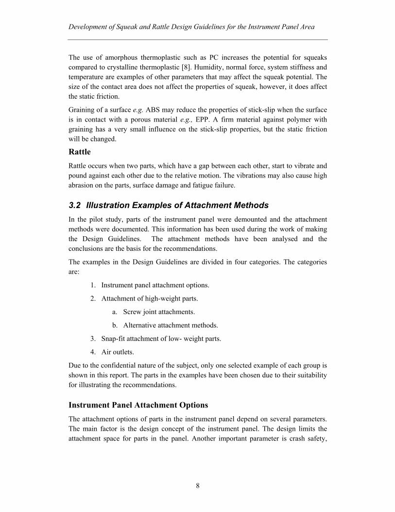
In the centre stack area a large radio carrier is welded into the instrument panel carrier (Figure 4). Both the radio and panel carriers are made in the same material: SMA. SMA is reinforced by glass fibre and has low compatibility concerning stick slip behaviour. The carrier has high stiffness and is separated in several sections.
Figure 4: The radio carrier is integrated into the panel carrier by welding. The centre stack area has high stiffness and the parts are well attached in separated sections.
Advantages
• Stiff structure.
• In the centre stack area, the components are mounted in separate sections:
- Reduces the risk for relative motion
Development of Squeak and Rattle Design Guidelines for the Instrument Panel Area
10
Disadvantages
• The panel carrier is made of SMA, which is reinforced by glass fibre:
- Low compatibility with regard to stick slip behaviour.
Conclusions
The concept of a radio carrier seems to function well. SMA as the construction material makes it particularly important to ensure that no relative motion occurs. Due to the properties of SMA, problems with squeak and rattle can easily arise if relative motions occur.
Attachment of High Weight Parts Using parts of high weight, it is extra important to have a rigid attachment. Screw joints are preferable, but the circumstances do not always allow them to be used. Parts attached by screw joints may take more time to mount and may cause ergonomic problems for the assembler.
Sometimes alternative attachment methods have to be considered. The examples in the design guidelines show parts of high weight attached both with screw joints and with alternative method.
Screw Joint Attachment
The placement and the stiffness of the attachment points are important to obtain the desired function of the attachment with screw joints. In the following risk analysis there are examples of screw joint attachments with varying results, depending on the attachment conditions.
In the Design Guidelines there are four examples of parts attached by screw joints. The examples are from BMW 325 Convertible, Saab 93 Sport Sedan and Volvo V70. The BMW’s attachment principle is good and functions well. The examples from Volvo show that screw joints do not guarantee good attachment, as good attachment conditions are also required for a well functioning screw joint attachment.
Example: Radio Unit in BMW 325 Convertible
Weight More than 2 kg Material
Contact surfaces: cast aluminium against TPO Front panel: unknown material
Development of Squeak and Rattle Design Guidelines for the Instrument Panel Area
11
Conditions for the Attachments
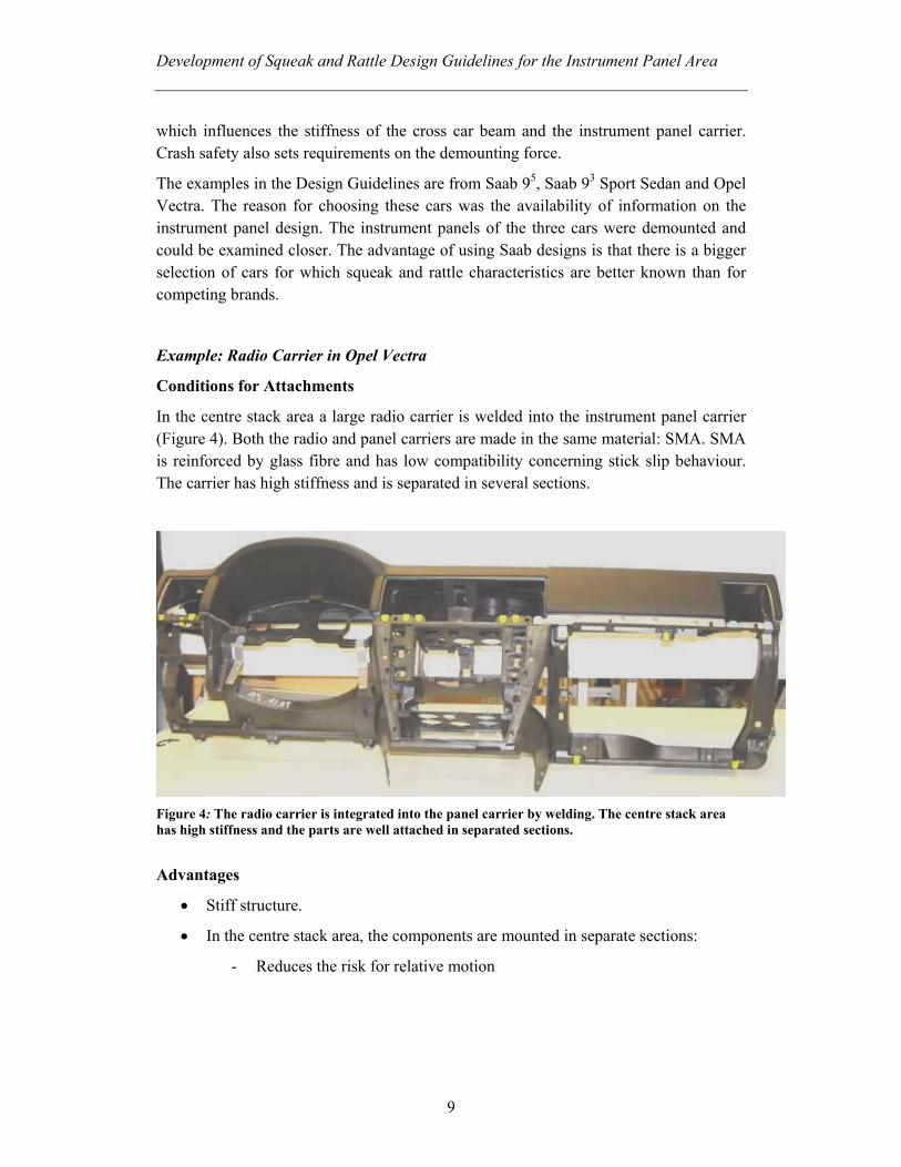
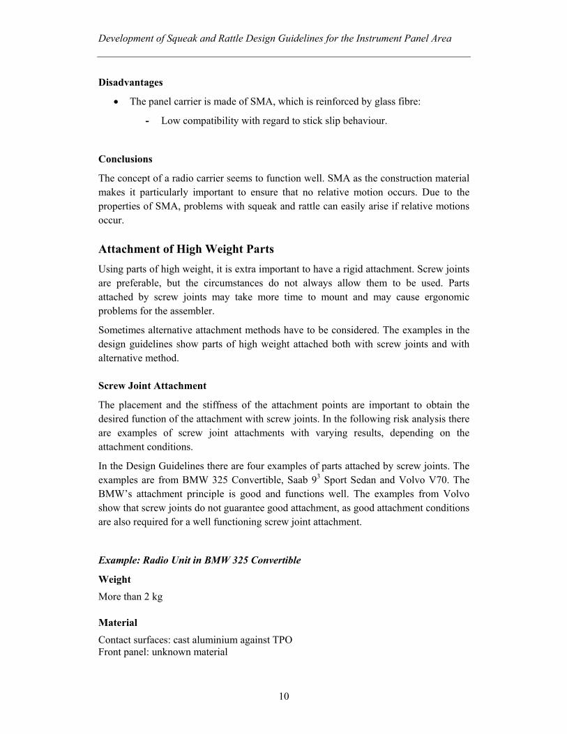
The instrument panel carrier and the attachment surface have high stiffness (Figure 5). The radio unit has no contact with other parts except of the screw hole (Figure 6) where the screw is shared with the middle air outlet. The radio will not affect and is not affected by other parts. It is possible to cover the screw joints with cover moulding (Figure 8).
Figure 5: The attachment support is integrated with the instrument panel.
Figure 6: The contact between the radio unit and the air outlet is limited to the surface around the screw holes.
Attachment support for screw joints Common screw holes for air outlet andradio unit
Contact surface against air outlet
Development of Squeak and Rattle Design Guidelines for the Instrument Panel Area
12
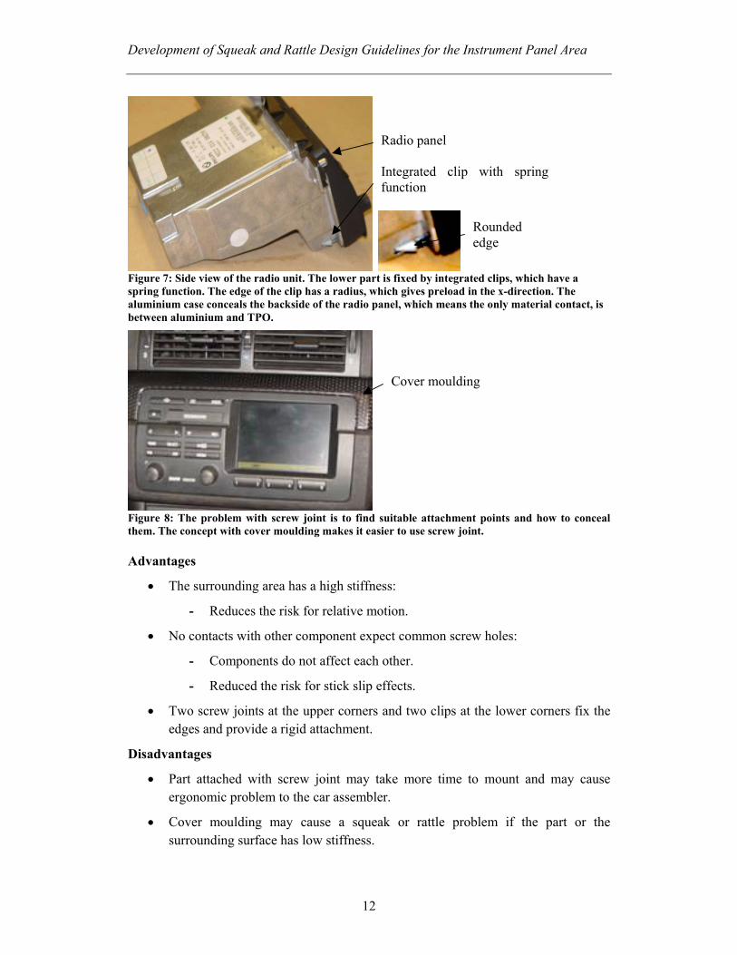
Figure 7: Side view of the radio unit. The lower part is fixed by integrated clips, which have a spring function. The edge of the clip has a radius, which gives preload in the x-direction. The aluminium case conceals the backside of the radio panel, which means the only material contact, is between aluminium and TPO.
Figure 8: The problem with screw joint is to find suitable attachment points and how to conceal them. The concept with cover moulding makes it easier to use screw joint. Advantages
• The surrounding area has a high stiffness:
- Reduces the risk for relative motion.
• No contacts with other component expect common screw holes:
- Components do not affect each other.
- Reduced the risk for stick slip effects.
• Two screw joints at the upper corners and two clips at the lower corners fix the edges and provide a rigid attachment.
Disadvantages
• Part attached with screw joint may take more time to mount and may cause ergonomic problem to the car assembler.
• Cover moulding may cause a squeak or rattle problem if the part or the surrounding surface has low stiffness.
Radio panel Integrated clip with spring function
Rounded edge
Cover moulding
Development of Squeak and Rattle Design Guidelines for the Instrument Panel Area
13
Conclusions
This attachment concept is good with regards to the squeak and rattle property. The surrounding structure of the cutout is stiff and the risk of vibration is low. The part is well attached with screws joints in the upper corners and snap fit in the lower part (Figure 7).
Alternative Attachment Methods
Sometimes the circumstances not allow the use of screw joint. Attaching heavy parts with snap fit should be avoided due to problems with relaxation of the snap. An alternative attachment method of attaching a radio unit is to use a sleeve. A sleeve eases the assembly and does not need large attachment surfaces.
The Design Guidelines contain two examples of heavy parts attached without screw joints. The examples are from Saab 95 and Opel Vectra. The both concepts work but Opel Vectra has better conditions due to they also use a screw joint in the rear end of the sleeve. There are also levels in a stiff radio carrier, which may reduce the risk of relative motions.
Example: Sleeve for the Radio Unit in Opel Vectra Weight
330g Material
Steel with coating. Contact surface: Steel with ED paint against SMA. Conditions for the Attachments
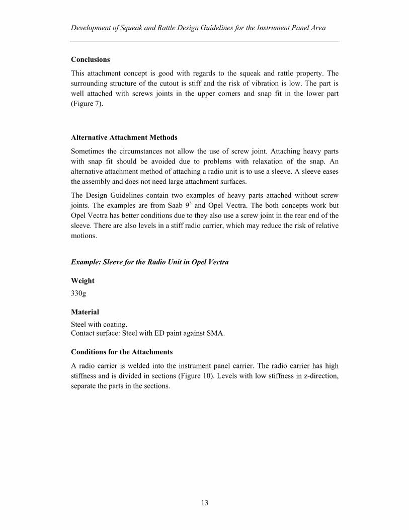
A radio carrier is welded into the instrument panel carrier. The radio carrier has high stiffness and is divided in sections (Figure 10). Levels with low stiffness in z-direction, separate the parts in the sections.

Development of Squeak and Rattle Design Guidelines for the Instrument Panel Area
14
Figure 9: Sleeve for the radio unit.
Figure 10: Radio carrier with levels. The whole surface on the sleeve except the front end and part of the back is in contact with the radio carrier.
Figure 11: The back of the radio carrier. The attachment support for the screw joint is integrated in the radio carrier and has high stiffness. A screw joint reduces the risk of relative motion.
Attachment support
Development of Squeak and Rattle Design Guidelines for the Instrument Panel Area
15
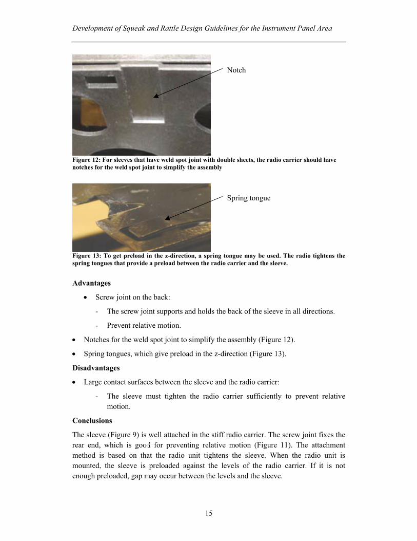
Figure 12: For sleeves that have weld spot joint with double sheets, the radio carrier should have notches for the weld spot joint to simplify the assembly
Figure 13: To get preload in the z-direction, a spring tongue may be used. The radio tightens the spring tongues that provide a preload between the radio carrier and the sleeve. Advantages
• Screw joint on the back:
- The screw joint supports and holds the back of the sleeve in all directions.
- Prevent relative motion.
• Notches for the weld spot joint to simplify the assembly (Figure 12).
• Spring tongues, which give preload in the z-direction (Figure 13).
Disadvantages
• Large contact surfaces between the sleeve and the radio carrier:
- The sleeve must tighten the radio carrier sufficiently to prevent relative motion.
Conclusions
The sleeve (Figure 9) is well attached in the stiff radio carrier. The screw joint fixes the rear end, which is good for preventing relative motion (Figure 11). The attachment method is based on that the radio unit tightens the sleeve. When the radio unit is mounted, the sleeve is preloaded against the levels of the radio carrier. If it is not enough preloaded, gap may occur between the levels and the sleeve.
Notch
Spring tongue
Development of Squeak and Rattle Design Guidelines for the Instrument Panel Area
16
Snap fit Attachment of Parts with Low Weight Parts, which have low weight, can be attached into the instrument panel with snap fits. To achieve the desired function of the snap fit, the snap must be trimmed sufficiently. If it is not trimmed sufficiently it will not give enough preload.
The examples in the Design Guidelines are from Saab 95 and Opel Vectra.
Example: MCP (Manual Control Panel) in Opel Vectra
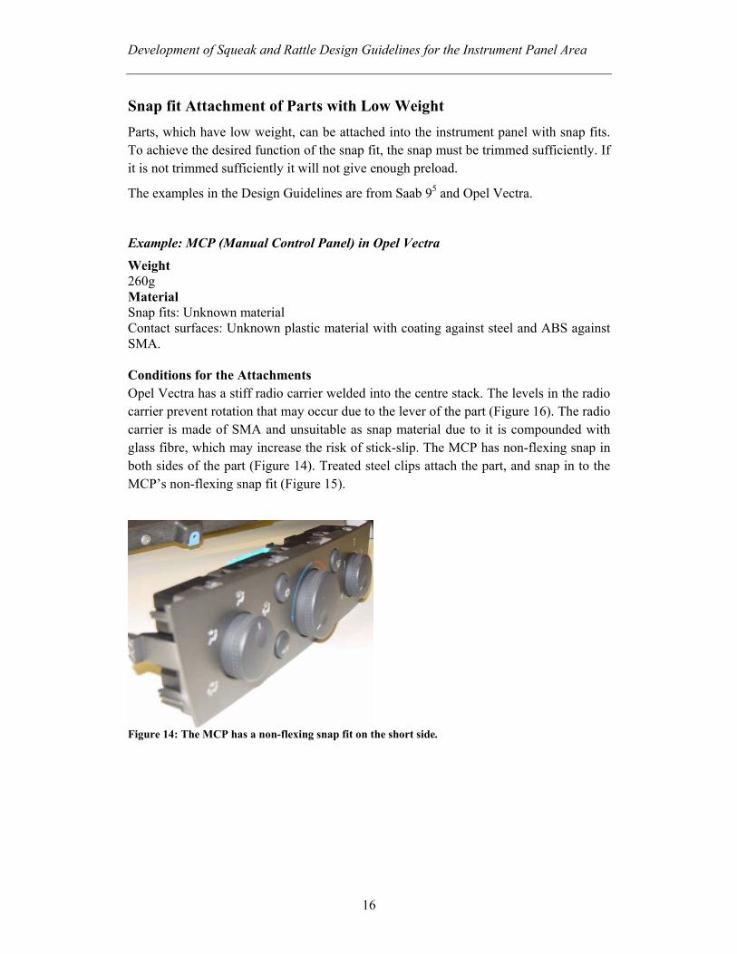
Weight 260g Material Snap fits: Unknown material Contact surfaces: Unknown plastic material with coating against steel and ABS against SMA. Conditions for the Attachments Opel Vectra has a stiff radio carrier welded into the centre stack. The levels in the radio carrier prevent rotation that may occur due to the lever of the part (Figure 16). The radio carrier is made of SMA and unsuitable as snap material due to it is compounded with glass fibre, which may increase the risk of stick-slip. The MCP has non-flexing snap in both sides of the part (Figure 14). Treated steel clips attach the part, and snap in to the MCP’s non-flexing snap fit (Figure 15).
Figure 14: The MCP has a non-flexing snap fit on the short side.
Development of Squeak and Rattle Design Guidelines for the Instrument Panel Area
17
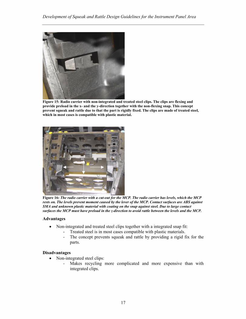
Figure 15: Radio carrier with non-integrated and treated steel clips. The clips are flexing and provide preload in the x- and the y-direction together with the non-flexing snap. This concept prevent squeak and rattle due to that the part is rigidly fixed. The clips are made of treated steel, which in most cases is compatible with plastic material.
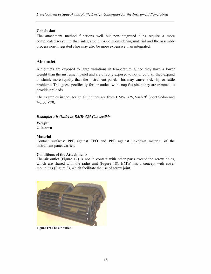
Figure 16: The radio carrier with a cut-out for the MCP. The radio carrier has levels, which the MCP rests on. The levels prevent moment caused by the lever of the MCP. Contact surfaces are ABS against SMA and unknown plastic material with coating on the snap against steel. Due to large contact surfaces the MCP must have preload in the z-direction to avoid rattle between the levels and the MCP.
Advantages
• Non-integrated and treated steel clips together with a integrated snap fit: - Treated steel is in most cases compatible with plastic materials. - The concept prevents squeak and rattle by providing a rigid fix for the
parts.
Disadvantages • Non-integrated steel clips:
- Makes recycling more complicated and more expensive than with integrated clips.
Development of Squeak and Rattle Design Guidelines for the Instrument Panel Area
18
Conclusion The attachment method functions well but non-integrated clips require a more complicated recycling than integrated clips do. Considering material and the assembly process non-integrated clips may also be more expensive than integrated.
Air outlet Air outlets are exposed to large variations in temperature. Since they have a lower weight than the instrument panel and are directly exposed to hot or cold air they expand or shrink more rapidly than the instrument panel. This may cause stick slip or rattle problems. This goes specifically for air outlets with snap fits since they are trimmed to provide preloads.
The examples in the Design Guidelines are from BMW 325, Saab 93 Sport Sedan and Volvo V70.
Example: Air Outlet in BMW 325 Convertible
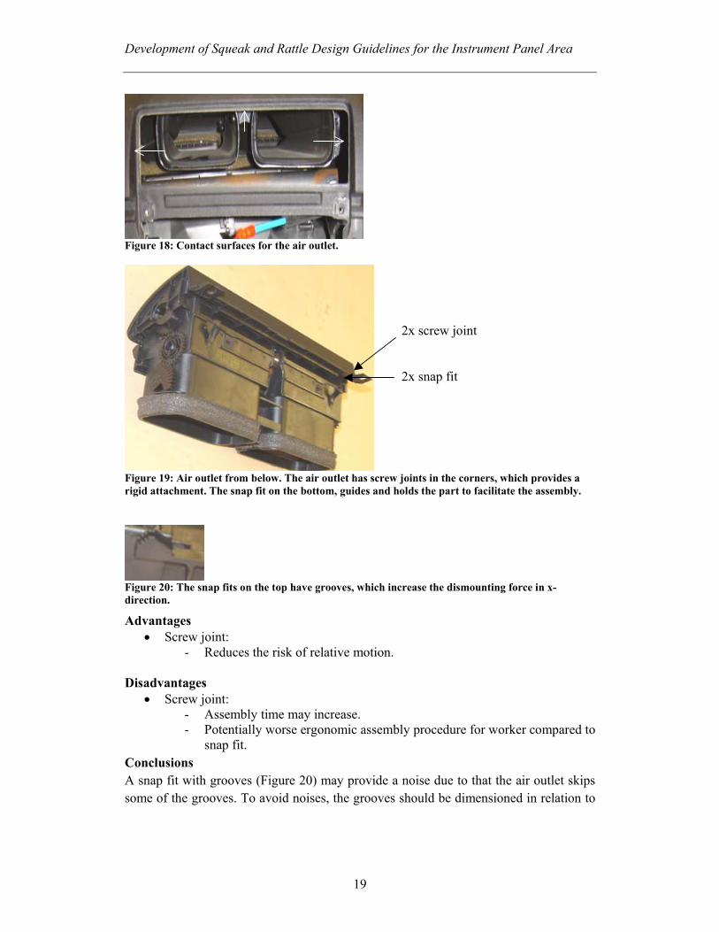
Weight Unknown Material Contact surfaces: PPE against TPO and PPE against unknown material of the instrument panel carrier. Conditions of the Attachments The air outlet (Figure 17) is not in contact with other parts except the screw holes, which are shared with the radio unit (Figure 18). BMW has a concept with cover mouldings (Figure 8), which facilitate the use of screw joint.
Figure 17: The air outlet.
Development of Squeak and Rattle Design Guidelines for the Instrument Panel Area
19
Figure 18: Contact surfaces for the air outlet.
Figure 19: Air outlet from below. The air outlet has screw joints in the corners, which provides a rigid attachment. The snap fit on the bottom, guides and holds the part to facilitate the assembly.
Figure 20: The snap fits on the top have grooves, which increase the dismounting force in x-direction.
Advantages • Screw joint:
- Reduces the risk of relative motion.
Disadvantages • Screw joint:
- Assembly time may increase. - Potentially worse ergonomic assembly procedure for worker compared to
snap fit. Conclusions A snap fit with grooves (Figure 20) may provide a noise due to that the air outlet skips some of the grooves. To avoid noises, the grooves should be dimensioned in relation to
2x screw joint 2x snap fit
Development of Squeak and Rattle Design Guidelines for the Instrument Panel Area
20
the loads. The attachment method with screw joint (Figure 19) prevents potential effects of temperature differences.
3.3 What to Consider When Designing an Instrument Panel Carrier
The dynamic stiffness of the instrument panel and its attachment to the car body has to be sufficient to reduce relative motion as well as absolute vibration. A structure with low stiffness easily starts to vibrate and relative motions between the panel and the mounted parts can occur. The first resonant frequency of the instrument panel in complete car should be a minimum of 35 Hz to avoid resonance with the major engine idle and road excitation frequencies.
How the attachment of the instrument panel carrier to the cross car beam are designed and located is very important to be able to fulfil the stiffness requirements. It is important to have a good connection between the stiff cross car beam and the less stiff instrument panel carrier to obtain a stiff instrument panel.
Since the main parts of the instrument panel are attached to the centre console it is important to have a rigid structure in this area. To obtain a rigid structure, the cross car beam support legs must have enough stiffness to fulfill the requirements.
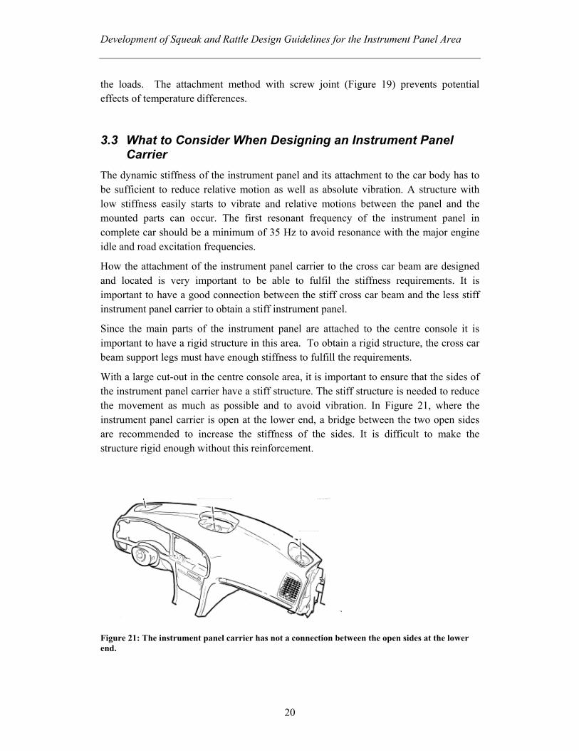
With a large cut-out in the centre console area, it is important to ensure that the sides of the instrument panel carrier have a stiff structure. The stiff structure is needed to reduce the movement as much as possible and to avoid vibration. In Figure 21, where the instrument panel carrier is open at the lower end, a bridge between the two open sides are recommended to increase the stiffness of the sides. It is difficult to make the structure rigid enough without this reinforcement.
Figure 21: The instrument panel carrier has not a connection between the open sides at the lower end.

Development of Squeak and Rattle Design Guidelines for the Instrument Panel Area
21
Another example of a big cutout is shown in Figure 22. The parts in the centre console fill the whole area and leaving not much structural support. This makes the structure weak and may cause insufficient support for the attached parts. Problems with relative motion and with fit and flush may occur.
Figure 22: A big cut-out in the centre stack area may cause problems.
To avoid tolerance problems it is important to have good guidance of the part. If the instrument panel carrier is not in exactly right position vs. cross car beam, accumulated tensions easily arise during the assembly process.
3.4 The effect of tolerances To fulfil the required function of an attachment method, it is important to consider potential effects of tolerances. Tolerances make that the position between the parts varies. Consequences of this can be that tensions accumulate during the assembly or considered preload may be lost. An example of when tolerances may cause problem is when a radio sleeve (Figure 23) is connected to the climate housing by a support pin.
Figure 23: Radio sleeve
Support pin
Development of Squeak and Rattle Design Guidelines for the Instrument Panel Area
22
The cone-shaped support pin’s function is to support the sleeve in the z-direction. It shall also give some preload in the both z- and x-direction. The sleeve is mounted into an instrument plate and is connected with the climate housing by the support pin. The chains of tolerances affect the distance between the instrument plate and the climate housing. If the tolerances makes the distance longer between the part, the support pin does not give the intentionally preload and a gap may occur. When the distance instead is shorter between the parts, the climate housing push the sleeve against the instrument plate by the support pin. This accumulates tension in the plate and increases the risk of squeaks and rattles.
3.5 What to Consider with Snap Fit Attachment When using snap fit, there are several things to consider.
• The weight of the parts
Heavy parts increase the risk for relative motion. Use screw joint instead of snap-in assemblies.
• Material of the snap
The material of the snap has a major influence on the function. Choose “right” material for desired function.
• Risk of relative motion
Appearance of relative motion depends on several parameters, e.g., movement in the specific area, stiffness in the snap-in surface, variation in temperature and tolerance between the parts. These parameters are important to consider when deciding how to secure a component.
• Requirement for rear end impact
To assure that the parts do not detach in a rear end impact, the angle α should be 90°. This applies mainly to parts with more weight. Negative effects of having 90° angles are that dismounting becomes more difficult and that there will be a gap between the components.
• Locator pins for easier assembly
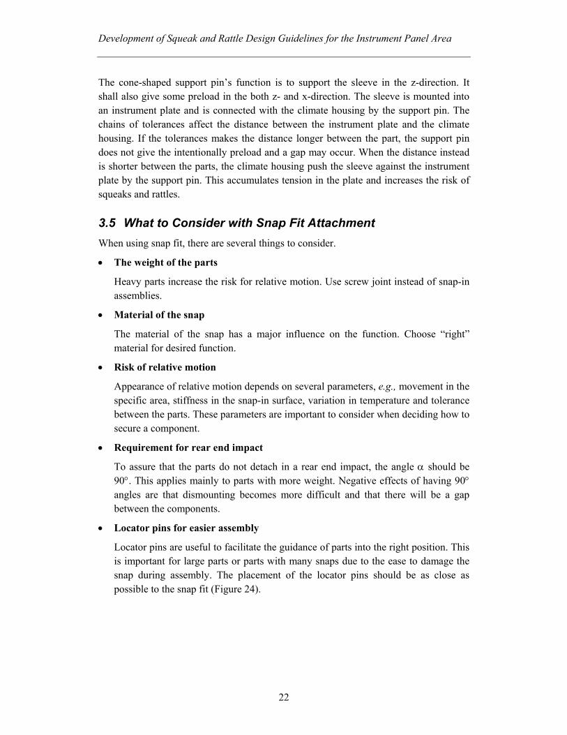
Locator pins are useful to facilitate the guidance of parts into the right position. This is important for large parts or parts with many snaps due to the ease to damage the snap during assembly. The placement of the locator pins should be as close as possible to the snap fit (Figure 24).
Development of Squeak and Rattle Design Guidelines for the Instrument Panel Area
23
Figure 24: Locator pins near the snap to facilitate the assembly.
• Snap fit as a supporting part
Snap fits should not be used as a supporting part. If the snap is used as a supporting part it is important to give the snap correct dimensions and use proper materials. If the supporting loads are operating during a long period of time the plastic materials are not capable to carry the load. If relaxation of the snap occur the parts may loose their stable attachments. This process accelerates in higher temperature.
• Preload
Parts that use snap-in assembly must have a preload to prevent movement. To avoid relative motion for parts attached by snap fit, the attachment support and the snap should be sufficiently trimmed. A snap fit, which not is sufficiently trimmed, may loose the preload and produce noise.
Design of the Snap
The shape of the snap is essential for the required function. • Radius
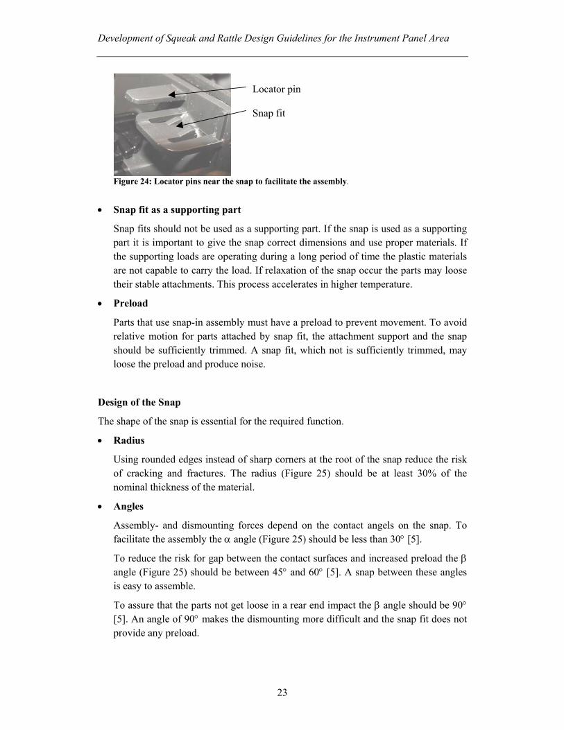
Using rounded edges instead of sharp corners at the root of the snap reduce the risk of cracking and fractures. The radius (Figure 25) should be at least 30% of the nominal thickness of the material.
• Angles
Assembly- and dismounting forces depend on the contact angels on the snap. To facilitate the assembly the α angle (Figure 25) should be less than 30° [5].
To reduce the risk for gap between the contact surfaces and increased preload the β angle (Figure 25) should be between 45° and 60° [5]. A snap between these angles is easy to assemble.
To assure that the parts not get loose in a rear end impact the β angle should be 90° [5]. An angle of 90° makes the dismounting more difficult and the snap fit does not provide any preload.
Locator pin Snap fit
Development of Squeak and Rattle Design Guidelines for the Instrument Panel Area
24
R
Figure 25: Definition of snap angles.
3.6 What to Consider with Screw Joint Attachment When using screw joint as an attachment method there are several things to consider. The recommendations in the Design Guidelines focus on the placement of the screw joint, stiffness of the attaching surfaces etc. Calculations parameters such as clamp load and torque are not treated in this document.
• Locator pin
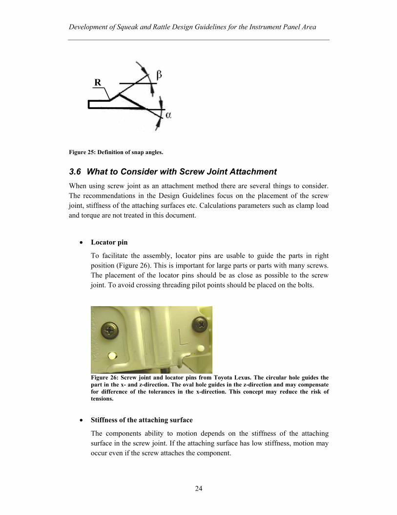
To facilitate the assembly, locator pins are usable to guide the parts in right position (Figure 26). This is important for large parts or parts with many screws. The placement of the locator pins should be as close as possible to the screw joint. To avoid crossing threading pilot points should be placed on the bolts.
Figure 26: Screw joint and locator pins from Toyota Lexus. The circular hole guides the part in the x- and z-direction. The oval hole guides in the z-direction and may compensate for difference of the tolerances in the x-direction. This concept may reduce the risk of tensions.
• Stiffness of the attaching surface
The components ability to motion depends on the stiffness of the attaching surface in the screw joint. If the attaching surface has low stiffness, motion may occur even if the screw attaches the component.
Development of Squeak and Rattle Design Guidelines for the Instrument Panel Area
25
• Placement
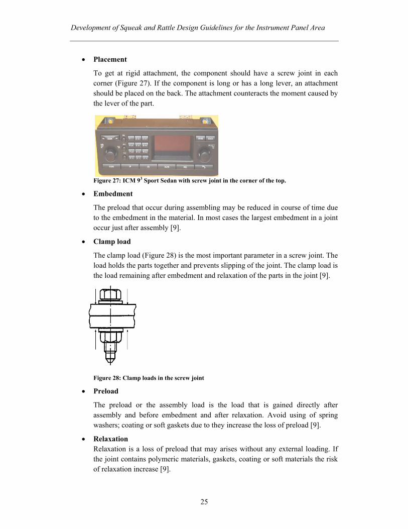
To get at rigid attachment, the component should have a screw joint in each corner (Figure 27). If the component is long or has a long lever, an attachment should be placed on the back. The attachment counteracts the moment caused by the lever of the part.
Figure 27: ICM 93 Sport Sedan with screw joint in the corner of the top.
• Embedment
The preload that occur during assembling may be reduced in course of time due to the embedment in the material. In most cases the largest embedment in a joint occur just after assembly [9].
• Clamp load
The clamp load (Figure 28) is the most important parameter in a screw joint. The load holds the parts together and prevents slipping of the joint. The clamp load is the load remaining after embedment and relaxation of the parts in the joint [9].
Figure 28: Clamp loads in the screw joint
• Preload
The preload or the assembly load is the load that is gained directly after assembly and before embedment and after relaxation. Avoid using of spring washers; coating or soft gaskets due to they increase the loss of preload [9].
• Relaxation Relaxation is a loss of preload that may arises without any external loading. If the joint contains polymeric materials, gaskets, coating or soft materials the risk of relaxation increase [9].
Development of Squeak and Rattle Design Guidelines for the Instrument Panel Area
26
Screw Joint for Plastics Materials
Construction of screw joint in thermoplastic materials is different from construction in steel. The plastic materials have a larger tendency to relaxation and embedment than steel. The plastic materials have also higher tendency to creep and are more sensitive to stress concentration.
If the screw joint will be reassembled a maximum of five times, self-tapping screws may be used. Is it a requirement on more frequently reassemblies or a safely screw joint a metal insert or a metal tap should be used.
The dismounting force for the self-tapping screw increase and the normal force for the screw head reduce in course of time. These occur particularly if the screw is assembled into a semi crystalline thermoplastic material.
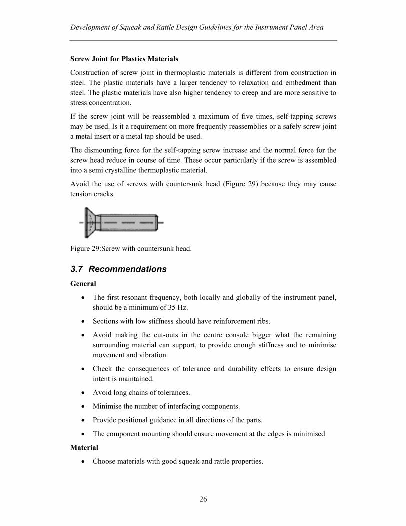
Avoid the use of screws with countersunk head (Figure 29) because they may cause tension cracks.
Figure 29:Screw with countersunk head.
3.7 Recommendations General
• The first resonant frequency, both locally and globally of the instrument panel, should be a minimum of 35 Hz.
• Sections with low stiffness should have reinforcement ribs.
• Avoid making the cut-outs in the centre console bigger what the remaining surrounding material can support, to provide enough stiffness and to minimise movement and vibration.
• Check the consequences of tolerance and durability effects to ensure design intent is maintained.
• Avoid long chains of tolerances.
• Minimise the number of interfacing components.
• Provide positional guidance in all directions of the parts.
• The component mounting should ensure movement at the edges is minimised
Material
• Choose materials with good squeak and rattle properties.
Development of Squeak and Rattle Design Guidelines for the Instrument Panel Area
27
• Check the consequences of how differences in temperature affect the material
• Allow contact between incompatible materials only at fixed locations or with isolation.
Snap Fits
• Be aware of how the temperature differences affect the snap fit.
• Snap fits with grooves increase the preload but may produce noise
• A snap with an angle less than 90° facilitates disassembly.
• The snap should be made of material with suitable properties.
• If possible, use integrated snap fits.
• The attachment support and the snap should be sufficiently trimmed to avoid relative motion.
• A snap with 90° angle gives no pretension and may lead to gaps between contact surfaces.
Screw Joints
• If using screw joints, ensure that the attachment points have enough stiffness to carry the weight of the part.
• If possible, place the screw joints close to the edges
4 Summary and Conclusions During the work with the guidelines it became more and more clear how parts are affected by each other. To find the source of the squeak and rattle you should not only look at the specific part. It is also necessary to be aware of the entire design concept.
The stiffness of the attachment area is the most important parameter to consider. The risk of relative motion depends on the excitation frequency and the amplitude of the vibration, while the resonance frequency depends on the stiffness of the part. Higher stiffness gives a higher first resonance frequency and thereby resonance problems at engine idle and road excitation frequencies are avoided. This is good for preventing squeak and rattle. Unfortunately, high stiffness is not good for all properties. In some areas it is better to have low stiffness. For example, in case of head impact in the instrument panel during a crash.
Another important parameter to consider is the effect of tolerances. Tolerances cause variation of the positions between the parts. When the positions of the parts vary, the intent of the design may not be maintained. Fit and flush problems may also occur due to that. The longer the chain of tolerances is, the more variation of the positions between the parts occur.
Development of Squeak and Rattle Design Guidelines for the Instrument Panel Area
28
Most parts in the instrument panel are made of plastic and are snapped in. When choosing materials it is important to know the material properties and behaviours in different environmental conditions. Inside a car there can be big differences in temperature. In extreme conditions it can be down to minus 40° C and up to plus 100° C. The snap function should remain in both low and high temperatures.
Ageing and relaxation of the plastic construction should also be considered. Due to ageing and relaxation a snap fit may lose function and problems with squeak and rattle may occur.
A requested styling of an instrument panel does not always provide the best attachment options. As an example, in Figure 22, the parts in the centre console fill the whole area leaving not much structural support. This makes the structure weak and may cause insufficient support for the attached parts. Problems with relative motion and with fit and flush occur.
Snap fit attachments have both advantages and disadvantages. One advantage is that it gives an easy and quick assembly. For low-weight parts it can be a well-functioning attachment method but for heavier parts, screw joints are preferable. If snap fit is used for a heavy part like a radio unit, the β angle (Figure 25) should be 90° to assure it fulfills rear end impact requirements. A negative aspect of using a snap with 90° angle is that a gap usually occurs between the part and the surrounding contact surfaces due to the absence of preload. This gap may cause a squeak and rattle problems.
Screw joint attachment is the preferable method to attach parts in order to avoid relative motion. To get a well functioning screw joint attachment, it is important that the attachment conditions are right. The placement of the screws joint is important and also the stiffness of the attachment points.
Designing the attachment method for a component is, as described in this report a complex work. There are many parameters to consider and sometimes you have to compromise between different desires, like the wished styling of the instrument panel and the best attachment options.
5 Future Work Future work may be to make the recommendations more quantitative. Examples of measurable targets are stiffness and clearances between the parts. Further investigations of how different materials affect each other with regard to squeak and rattle properties would also be useful.

Development of Squeak and Rattle Design Guidelines for the Instrument Panel Area
29
6 References [1] Arne Carlsson,1998, “Coordinate system for cars”, Trollhättan, Saab Automobile
AB, Saab standard 3581.
[2] Arne Carlsson, 1998, “Master location system”, Trollhättan, Saab Automobile AB, Saab standard 3546.
[3] Edward Lee, Martin Trapp, 1997, “Behavior of Automotive InteriorPolymericMaterial Pairs Society of Automotive Engineers”, Norm EISS-Virgina Tech,., Frictional.
[4] Dr Daams, Overview-lecture about the topic Squeak & rattle elimination, Squeak & Rattle forum November 2003, Birmingham, England.
[5] Berggren, K., Jansson, J-F., Nilsson, L-Å., Strömvall, H-E.1997. ”Konstruera i plast”. Göteborg: Industrilitteratur AB
[6] Strömvall, H-E. 2002. ”Producera i plast”. Borås: Industrilitteratur AB
[7] Å. Emanuelsson, 1994, “Plastic”, Trollhättan, Saab Automobile AB, Saab standard 2153.
[8] Cecilia Pettersson, 1998, “Evaluation of squeak and rattle properties of polymeric materials”, Department of polymer technology, Chalmers university of technology,Gothenburg
[9] Isaksson,1994, kurslitteratur “Skruvförbandsteknologi”, Bulten Automotive AB