Embed Size (px)
Citation preview

EUROPEAN COMMISSIONEURO-MEDITERRANEAN PARTNERSHIP
Development of Tools and Guidelines for the Promotion of the Sustainable
Urban Wastewater Treatment and Reuse in the Agricultural Production
in the Mediterranean Countries
(MEDAWARE)
Task 4: Urban Wastewater Treatment Technologies Part I
December 2004
1
MEDAWAREMEDAWARE ME8/AIDCO/2001/0515/59341-P033 ME8/AIDCO/2001/0515/59341-P033

Table of contentsTable of contents...............................................................................1List of Tables.....................................................................................4List of Figures...................................................................................71. Introduction...................................................................................92. Wastewater..................................................................................11
2a. Origin and Composition...................................................................112b. Domestic Wastewater......................................................................122c. Wastewater Flowrate.......................................................................142d. Impact of Wastewater (Untreated)..................................................14
3. Wastewater Treatment................................................................163a. Types of Reactors............................................................................173b. Flow Regimes..................................................................................193c. Process Selection.............................................................................20
4. Unit Processes and Operations of Wastewater Treatment.........255. Preliminary Treatment................................................................34
5a. Coarse Solids Reduction..................................................................34i. Screening...................................................................................................34ii. Comminutors............................................................................................36iii. Macerators..............................................................................................36iv. Grinders...................................................................................................37
5b. Grit Removal....................................................................................37i. Horizontal Flow Grit Chambers.................................................................38ii. Aerated Grit Chambers.............................................................................38iii. Vortex-type Grit Chambers......................................................................39
5c. Flow Equalisation............................................................................396. Primary Treatment......................................................................41
6a. Sedimentation Basins......................................................................41i. Rectangular Tanks.....................................................................................41ii. Circular Tanks..........................................................................................43Performance.................................................................................................44Important Design Considerations.................................................................45High-Rate Clarification.................................................................................45
6b. Flotation..........................................................................................46i. Dissolved air flotation................................................................................46ii. Dispersed air flotation..............................................................................46Chemical Additives.......................................................................................47
7. Secondary Treatment..................................................................487a. Activated Sludge..............................................................................48
Process Description......................................................................................48Process Options............................................................................................50Comparison of Process Options....................................................................54Effluent Characteristics................................................................................55Secondary Clarification for Activated Sludge...............................................56
7b. Trickling Filter................................................................................56Process Description......................................................................................57Process Options............................................................................................58Effluent Characteristics................................................................................59
7c. Rotating Biological Contactor..........................................................60Unit Description...........................................................................................60
2

Process Options............................................................................................62Process Advantages and Disadvantages.......................................................62Effluent Characteristics................................................................................63
7d. Lagoons...........................................................................................63Process Description......................................................................................63Process Options............................................................................................65Comparison of Process Options....................................................................67Typical Applications......................................................................................67
7e. Anaerobic Processes........................................................................68i. Anaerobic Digestion..................................................................................68ii. Low-Rate Anaerobic Processes.................................................................69iii. High-Rate Anaerobic Processes...............................................................70iv. Solids Fermentation Processes................................................................75Comparison of Anaerobic Processes.............................................................76Typical Applications......................................................................................77
8. Tertiary Treatment......................................................................798a. Removal of Nutrients.......................................................................79
i. Biological Nitrogen Removal.....................................................................79ii. Phosphorus Removal................................................................................81
8b. Disinfection.....................................................................................85Types of disinfectants...................................................................................85Comparison of available methods.................................................................86Factors Affecting Performance of Disinfectants...........................................87i. Chlorine & Chlorine Compounds...............................................................87ii. Ozone........................................................................................................90iii. Other Chemical Methods.........................................................................91iv. Ultraviolet (UV) Radiation.......................................................................91Comparison of methods................................................................................93
9. Advanced Treatment...................................................................95A9a. Membrane Filtration Processes....................................................95
Process Classification...................................................................................95Operation......................................................................................................96Applications..................................................................................................96Comparison of Methods................................................................................98
A9b. Activated Carbon Adsorption........................................................99Applications in Wastewater Treatment.........................................................99Granular and Powdered Activated Carbon Treatment...............................100
10. Additional Components Required...........................................10110a. Chemical Feeders........................................................................10110b. Mixers..........................................................................................103
Design parameters.....................................................................................10410c. pH Neutralisation........................................................................104
Options.......................................................................................................104
9. Sewage Sludge Treatment Methods.........................................106A9a. Conditioning................................................................................107A9b. Thickening...................................................................................108A9c. Dewatering..................................................................................110A9d. Stabilisation/ Disinfection...........................................................112A9e. Heat Drying.................................................................................115A9f. Recently developed methods.......................................................115
Bibliography and References........................................................118
3

List of TablesTABLE 1: Typical Wastewater Analysis at Various Points in Its Course.............................................................................................12TABLE 2: Important wastewater contaminants..............................14TABLE 3: Levels of Wastewater Treatment....................................16TABLE 4: Classification of Common Wastewater Treatment Processes According To Level of Advancement..............................17TABLE 5: Principal Types of Reactors Used In Wastewater Treatment Plants.............................................................................17TABLE 6: Constituent Removal Efficiency, According To Type of Process/ Operation Used.................................................................20TABLE 7: Expected Removals of Excreted Microorganisms in Various Wastewater Treatment Systems........................................21TABLE 8: Factors to Be Considered When Choosing Treatment for Wastewater Along With the Efficiency of Some Processes for the Specific Factors...............................................................................23TABLE 9: Unit Operations, Unit Processes and Systems Used For Removal/ Reduction Important Parameters in Wastewater............25TABLE 10: Unit Processes/ Operations to Be Described In This Project, For Respective Treatment.................................................32TABLE 11: Description of Coarse Screens......................................34TABLE 12: Advantages & Disadvantages of Various Types of Coarse Screens............................................................................................35TABLE 13: Typical Design Data for Horizontal Flow Grit Chambers.........................................................................................................38TABLE 14: Typical design data for aerated grit chambers.............39TABLE 15: Typical Design Information for Primary Sedimentation Tanks...............................................................................................42TABLE 16: Summary of Features of High-Rate Clarification Processes.........................................................................................45TABLE 17: Advantages and disadvantages of dispersed-air flotation.........................................................................................................47TABLE 18: Design Criteria for Conventional Activated Sludge Treatment Facilities........................................................................50TABLE 19: Design Criteria for Conventional Extended Aeration Activated Sludge Treatment Facilities............................................53TABLE 20: Comparison of Activated Sludge Process Options........54TABLE 21: Typical design information for secondary clarifiers of the activated sludge processa..........................................................56TABLE 22: Trickling Filter Process Comparison............................58
4

TABLE 23: Trickling Filter Applications, Loadings and Effluent Quality.............................................................................................60TABLE 24: Advantages and Disadvantages of Rotating Biological Conductors......................................................................................63TABLE 25: Typical Design Information for Secondary Clarifiers of the Activated Sludge Process..........................................................63TABLE 26: Lagoon Process Comparison.........................................67TABLE 27: Typical Lagoon Applications.........................................68TABLE 28: Typical High-Rate Anaerobic Processes Performance..71TABLE 29: Anaerobic Treatment Process Comparison for Organic Stabilisation.....................................................................................76TABLE 30: Inorganic Chemicals Used Most Commonly For Coagulation (And Chemical Precipitation) In Wastewater Treatment.........................................................................................................83TABLE 31: Characteristics of the ideal disinfectant.......................85TABLE 32: Removal or destruction of bacteria by different treatment processes or operations.................................................86TABLE 33: Comparison of commonly used disinfectants to the ideal case..................................................................................................86TABLE 34: Impact of wastewater constituents on the use of chlorine for wastewater disinfection...............................................88TABLE 35: Concerns associated with chlorine use.........................89TABLE 36: Typical energy requirements for the application of ozone...............................................................................................90TABLE 37: Typical operational characteristics for UV lamps.........92TABLE 38: Impact of wastewater constituents on the use of UV radiation for wastewater disinfection.............................................92TABLE 39: Advantages and disadvantages of chlorine, chlorine dioxide, ozone and UV for wastewater disinfection........................93TABLE 40: General Characteristics of Membrane Processes.........95TABLE 41: Typical applications for membrane technologies in wastewater treatment.....................................................................96TABLE 42: Application of membrane technologies for the removal of specific constituents found in wastewater..................................97TABLE 43: Typical characteristics of membrane technologies used in wastewater treatment applications.............................................97TABLE 44: Advantages and Disadvantages of Microfiltration and Ultrafiltration, and Reverse Osmosis; I.E. Membrane Technologies Used In Wastewater Treatment Applications.................................98
5

TABLE 45: Comparison of granular and powdered activated carbon.........................................................................................................99TABLE 46: Advantages and disadvantages associated with wastewater treatment with Granular Activated Carbon and Powered Activated Carbon............................................................100TABLE 47: Basic characteristics and functioning of dry feeders. 102TABLE 48: Typical mixing times and applications for different mixing and flocculation devices used in wastewater treatment facilities.........................................................................................103TABLE 49: Typical detention time and velocity gradient G values for mixing and flocculation in wastewater treatment...................104TABLE 50: characteristics of the most commonly used chemicals for pH Control/ Neutralisation......................................................104TABLE 51: Chemicals typically used for pH Control/ Neutralisation.......................................................................................................105TABLE 52: Methods available for sludge treatment.....................106TABLE 53: Comparison of conditioning processes.......................107TABLE 54: Comparison of thickening processes..........................109TABLE 55: Comparison of dewatering processes.........................111TABLE 56: Comparison of most commonly used stabilisation processes.......................................................................................114
6

List of FiguresFIGURE 1: Typical Composition of Wastewater.............................11FIGURE 2: Sources of Household Wastewater, Showing Wastewater from Toilet, Kitchen, Bathroom, Laundry and Others 13FIGURE 4: Flow Regimes Commonly Used In Treatment of Wastewater......................................................................................20FIGURE 5: Relative Capital and Operational Costs of the Main Stages of Processes, Indication of Where Is More Effective To Spend Money, Depending On the % Removal of Pollutants That the Treatment Plant Has A Target........................................................22FIGURE 6: Typical Municipal Wastewater Treatment Facility.......30FIGURE 7: Unit Operations and Unit Processes of Which the Treatment Levels Are Composed....................................................31FIGURE 8: Definition Sketch for Types of Screens Used In Wastewater Treatment....................................................................34FIGURE 9: A Schematic Diagram of the Activated Sludge Process48FIGURE 10: Bioreatctor configurations for Step-Feed Activated Sludge (SFAS).................................................................................51FIGURE 11: Configurations used for Completely Mixed Activated Sludge (CMAS)................................................................................52FIGURE 12: Selector activated sludge (SAS) process....................54FIGURE 13: Schematic Diagram of a Trickling Filter....................57FIGURE 14: Examples of Rotating Biological Contactors Trains. . .61FIGURE 15: Schematic Diagram of a Lagoon (Vertical Dimension Exaggerated)...................................................................................64FIGURE 16: Low Rate Anaerobic Process Using an Earthen Basin70FIGURE 17: Anaerobic Filter..........................................................73FIGURE 18: Hybrid Upflow Anaerobic Sludge Blanket And Anaerobic Filters Process...............................................................74FIGURE 19: Downflow Stationary Fixed Film Process...................74FIGURE 20: Fluidised Bed and Expanded Bed process..................75FIGURE 21: Nitrogen Transformations in biological treatment processes.........................................................................................80FIGURE 22: Types of denitrification processes and the reactors used for their implementation.........................................................81FIGURE 23: Typical reactor configuration for biological phosphorus removal............................................................................................81FIGURE 24: Theoretical Breakpoint Chlorination Scheme at: 1.0mg/L ammonia-nitrogen; pH 7; temperature 25˚C; contact time
7

2 hours.............................................................................................88FIGURE 25: Affect of pH on the form of chlorine; Forms of Chlorine Present in Water across the pH range of 0 - 9................................88FIGURE 26: Classification of chemical-feed systems....................101
8

1. Introduction
As it is widely known and accepted, water is an essential and basic human need for urban, industrial and agricultural use and has to be considered as a limited resource. Only 1% of the total water resources in the world can be considered as fresh water and by 2025 it is estimated that nearly one-third of the population of developing countries (approximately 2.7 billion people), will live in regions of severe water scarcity. As a result, the amount of water used in irrigation has to be reduced, in order for the domestic, industrial and environmental sector to survive.
Additionally, human interference causes water pollution, e.g. by industrial effluents, agricultural pollution or domestic sewage, which will increase. As a result the world's primary water supply will need to increase by 41% to meet the needs of all sectors which will be largely due to the increase in the world population (Seckler D. et al., 2000).
Water reuse and recycling are the only solutions to close the loop between water supply and wastewater disposal. Within the past years, the cost of treating wastewater to a high quality has reduced to feasible. Consequently, in many parts of the world reclaimed water is used as a water resource. Hence, wastewater could be regarded as a resource that could be put to beneficial use rather than wasted.
Water reuse accomplishes usually two fundamental functions: the treated effluent is used as a water resource for beneficial purpose and the effluent is kept out of streams, lakes, and beaches: thus reducing pollution of surface water and groundwater (Asano, 1998). Additionally, valuable substances and heat recovery can be achieved by water recycling obtaining a zero emission process.
Objectives and Content The aim of this project is to: (i) review all urban wastewater technologies, methods and
systems including innovative ones; (Report Part I) and (ii) develop specifications for the urban wastewater treatment
technologies and systems, the aim being the presentation of technologies and systems, where the effluent can be safely reused, while on the other hand these techniques will not be extremely expensive to be implemented (in terms of e.g. construction, operation, maintenance, labour, etc), (Report Part II)
The overall outcome of this project is specifications and information sheets for the urban wastewater treatment technologies and
9

systems that can be adapted to the regional context of the Mediterranean countries.
10

2. Wastewater
In this section of the project, the primary concern is to make the reader understand what wastewater is; which its components according to origins are and their impact in case of discharge into the environment without any treatment; and variations is flow. This information is critical in designing a wastewater treatment plant.
2a. Origin and Composition
The main constituents of wastewater are solids, soluble organics and waterborne pathogens (figure 1), originating from domestic and industrial water uses. The composition/ratios that exist between components vary considerably, depending on local practices percentage and type of industrial waste, and amount of dilution caused by inflow/infiltration.
Raw Wastewater99.9% 0.1%
Water Solids
70% 30%Organic Inorganic
65% 25% 10%Proteins Carbohydrat
esFats Grit Salts Metals
FIGURE 1: Typical Composition of WastewaterSource: Butler D. and Smith S., 2003
Solids: consist of 70:30 ratio of organic to inorganic. The organic fraction composes of body wastes, food waste, paper, rags and biological cells, whereas the inorganic, consists of surface sediments and soil. Solids have to be removed prior discharge, otherwise, they shall settle in the receiving watercourse.
Soluble Organics: Composed mainly of proteins (amino acids), carbohydrates (sugar, starch, cellulose) and lipids (fats, oils, grease). All these substances contain carbon that can be converted to carbon dioxide biologically. Consequently, the oxygen demand exerted on receiving water is due to soluble organics.
Waterborne pathogens: originate from infected people, and are primarily bacteria, viruses and protozoa. These organisms can pose a direct hazard to public health. Coliform bacteria are used as indicator of disease-causing organisms in wastewater.
Other components of wastewater are minerals and metals. Some nitrogen is also present due to the presence of proteins, and other nutrients such as phosphorus (6-20 mg/l). The concentration of
11

ammonia (NH3) can range from 12-50 mg/l. The parameters that are of greater importance for wastewater treatment are Biochemical Oxygen Demand (BOD) and Suspended Solids (SS).
BOD is a measure of the amount of biodegradable organic substances in the water. As naturally occurring bacteria consume these organic substances they take up oxygen from the water for respiration, while converting the substances into energy and materials for growth. In other words, BOD, the biochemical oxygen demand, measures the amount of oxygen microorganisms require to break down wastewater. On average each person produces about 60 g of BOD in faecal and other materials. The concentration of BOD in wastewater varies depending on the volume of water used to convey the faecal materials. For example if the total water usage per person is 200 L per day, then the resulting wastewater will have a BOD concentration of 300 mg/L. Untreated wastewater has a typical BOD value ranging from 100 mg/l to 300 mg/l.
A typical composition analysis is shown in the table that follows (table 1), for crude wastewater, settled and effluent from a wastewater treatment plant.
TABLE 1: Typical Wastewater Analysis at Various Points in Its Course
Characteristic (mg/l)
SourceCrude Settled Final
EffluentBOD 300 175 20COD 700 400 90TOC 200 90 30SS 400 200 30NH4 - N 40 40 5NO3 - N <1 <1 20
2b. Domestic Wastewater
Household (domestic) wastewater derives from a number of sources (Figure 2). Wastewater from the toilet is termed 'blackwater'. It has a high content of solids and contributes a significant amount of nutrients (nitrogen, N and phosphorus, P). Blackwater can be further separated into faecal materials and urine. Each person on average excretes about 4 kg N and 0.4 kg P in urine, and 0.55 kg N and 0.18 kg P in faeces per year. In Sweden it has been estimated that the nutrient value of urine from the total population is equivalent to 15 - 20 % of chemical fertiliser use in 1993 (Esrey et al., 1998).
Greywater consists of water from washing of clothes, from bathing/showering and from the kitchen. The latter may have a high content of solids and grease, and depending on its intended reuse/treatment or disposal can be combined with toilet wastes and
12

form the blackwater. Both greywater and blackwater may contain human pathogens, though concentrations are generally higher in blackwater.
FIGURE 2: Sources of Household Wastewater, Showing Wastewater from Toilet, Kitchen, Bathroom, Laundry and Others Based On Diagram from UNEP, 2000
The volume of wastewater and concentration of pollutants produced depend on the method of volume of water used and water conservation measures. The use of flushing toilets results in higher wastewater volumes and lower concentrations. The characteristics of wastewater differ regionally, according to factors such as lifestyle, water availability etc.
The flow of wastewater is generally variable with peak flows coinciding with high household activities in the morning and evening, while in the night minimal flow occurs. Figure 3 shows the typical diurnal domestic flow pattern, as it was found in the United Kingdom by School of Civil Engineering and Geosciences University of Newcastle upon Tyne (2003). Pollutant loads vary in a similar manner. More details on the variations of flowrate before and through the treatment can be found in a later chapter.
2c. Wastewater FlowrateVariations in wastewater flowrate are experienced according to the time of the day, the day of the week and season of the year. Quantifying these variations is important for the design and the
13
Toilet
Black Wate
r
Kitchen sink
Dish washer Bath-
shower
Clothes washer
Miscellaneous
Storm Water
GREY WATER
Combined wastewaterWASTEWATER
FIGURE 3: Typical Diurnal Domestic Wastewater Flow Pattern

operation of a treatment plant. Using maximum hour, day, month and other time periods, peaking factors can be developed. Peaking factors are useful in making estimations for the maximum hydraulic conditions that could be experienced. Peaking factor can be calculated from equation I (Metcalf & Eddy, 2003):
(I)The equation is used due to the difficulty that one can experience while comparing numerical peak flow values from different wastewater treatment units; normalised values generated from the equation can be compared. In cases where flowrate data is available, analysis of data of at least 3 years should take place for the definition of peak (and average) flows of wastewater to the treatment plant.
2d. Impact of Wastewater (Untreated)
The most important wastewater contaminants are suspended solids, biodegradable organics, pathogens, nutrients, refractory organics, heavy metals and dissolved inorganic solids (Table 2).
TABLE 2: Important wastewater contaminantsContaminant Source Environmental SignificanceSuspended Solids (SS)
Domestic use, industrial wastes, erosion by infiltration/ inflow
Cause sludge deposits and anaerobic conditions in aquatic environment.
Biodegradable Organics
Domestic and industrial waste
Cause biological degradation, which may use up oxygen in receiving water and result in undesirable conditions
Pathogens Domestic waste Transmit communicable diseases
Nutrients Domestic and industrial waste
May cause eutrophication
Refractory Organics Industrial waste May cause taste and odour problems, may be toxic or carcinogen
Heavy Metals Industrial waste, mining etc. Are toxicDissolved Inorganic Solids
Increases above level in water supply by domestic and/or industrial use
May interfere with effluent reuse
Solids in urban wastewater form sediments and can eventually clog drains, streams and rivers. Grease particles form scum and are aesthetically undesirable.
The nutrients N and P cause eutrophication of water bodies. Lakes and slow moving waters are affected more than faster flowing waters. In the former, the algae are fertilised by the nutrients and settle as sediment when they decay. The nutrients are released regularly to the water column by the sediment which acts as a store of nutrients. As a result the cycle of bloom and decay of the algae is intensified. In the early stages of eutrophication aquatic
14

life is made more abundant, because fish, for example, graze on the algae. As the concentration of algae increases, the decaying algae contribute to BOD and the water is deoxygenated. Thus wastewater treated for BOD reduction but still high in nutrients, can still have a significant impact on the receiving water. Additionally, some algae produce toxins which can be harmful to bird life and irritate skins coming into contact with the water. Eutrophic water adds to the cost of water treatment, when the water is used for drinking purposes.
Heavy metals and possible toxic and household hazardous substances are other sources of pollution. Heavy metals include copper, zinc, cadmium, nickel, chromium and lead, originating from materials used in the making of pipes for the supply of drinking water, household cleaning agents used, and for stormwater the type of materials used for roofing and guttering. In high enough concentrations these heavy metals are toxic to bacteria, plants and animals, and to people. Other sources of toxic materials are substances disposed with household wastewater, such as medicines, pesticides and herbicides which are no longer used, excess solvents, paints and other household chemicals. These substances can corrode sewer pipes and seriously affect operation of treatment plants. They will also limit the potential of water reuse, and therefore should not be disposed with household wastewater.
To prevent degradation of the receiving environment wastewater needs to be treated. Treatment basically consists of removing solids from the wastewater and reducing its BOD. From there on, the degree of treatment that is required dependents on the final use of the effluent: in cases where is to be disposed in water bodies, the treatment depends on the capacity of the receiving environment to assimilate the remaining organic wastes.
In this chapter, the basic characteristics of wastewater have been described, as introduction to wastewater treatment, which is widely discussed in the next chapter.
15

3. Wastewater Treatment
Wastewater treatment is categorised in levels of treatment. Following, a description is given for the types of reactors and flow regimes along with examples of use in wastewater treatment; and the criteria that should be used for choosing the appropriate unit processes for a wastewater treatment plant.
The aim of a wastewater treatment is to enable wastewater to be disposed safely, without being a danger to public health, and without polluting watercourses or causing other environmental nuisance.
Unit operations/ processes: are the methods used for treating wastewater using physical forces and biological or chemical reactions.Treatment system: is a combination of unit processes/ operations designed to reduce certain wastewater constituents (reduce or remove organic matter, solids, nutrients, disease-causing organisms and other pollutants) to an acceptable level depending on the destination of the effluent (see “Effluent Standards”). The configurations possible are numerous, but a number of standard systems have been developed.
The table that follows (Table 3) describes briefly the treatment levels used in wastewater treatment. The objective of preliminary treatment is to prevent damage from occurring at later treatment steps. In primary treatment, by the use of physical operations (primarily sedimentation) floating and settleable materials are removed from wastewater, and could be enhanced by the addition of chemicals. The majority of organic mater is removed in secondary treatment, by the use of biological and chemical processes. In advanced treatment, residual suspended solids and other constituents of wastewater that cannot be reduced by previous treatment are removed by the application of combinations of unit operation and processes.
TABLE 3: Levels of Wastewater Treatment Treatment Level
Description
Preliminary Removal of wastewater constituents such as rags, sticks, floatables, grit, and grease that may cause maintenance or operational problems with the treatment operations, processes, and ancillary systems
Primary Removal or portion of the suspended solids and organic matter from wastewater
Secondary Removal of biodegradable organic matter (in solution or suspension) and suspended solids. Disinfection is also typically included in the definition of conventional secondary treatment
Tertiary Removal or residual suspended solids (after secondary treatment), usually by granular medium filtration or microscreens. Disinfection is also typically a part of tertiary treatment. Nutrient removal is often included in this definition
Advanced Removal of dissolved and suspended materials remaining after normal
16

biological treatment when required for various water reuse applications
Adapted In Part from Tchobanoglous G. & Crites R., 1998Each of the treatment levels, consist of unit processes. The decision of which processes should be included in a wastewater treatment plant, depend on the factors described in the section that follows (A3a. Process selection).
Table 4, classifies the most common wastewater treatment processes as proposed by WHO and UNEP in the publication of 1997, “Water Pollution Control – A Guide to the Use of Water Quality Management Principles”.
TABLE 4: Classification of Common Wastewater Treatment Processes According To Level of Advancement Primary Secondary Tertiary AdvancedBar or bow screen Activated sludge Nitrification Chemical treatmentGrit removal Extended aeration Denitrification Reverse osmosisPrimary sedimentation
Aerated lagoon Chemical precipitation
Electrodialysis
Comminution Trickling filter Disinfection Carbon adsorptionOil/fat removal Rotating bio-discs (Direct) filtration Selective ion
exchangeFlow equalisation Anaerobic
treatment/UASBChemical oxidation Hyperfiltration
pH neutralisation Anaerobic filter Biological P removal OxidationImhoff tank Stabilisation ponds Constructed
wetlandsDetoxification
Constructed wetlands AquacultureAquaculture
Source: WHO/ UNEP, 1997
3a. Types of Reactors
A number of wastewater treatment technologies are currently available in the market, of which the majority can be used in most of the unit processes involved in a wastewater treatment plant. The principal types of reactors used for wastewater treatment are shown in Table 5: batch reactor, plug-flow reactor, complete-mix reactor, arbitrary-flow reactor, complete-mix reactors in series, packed-bed reactor and fluidised-bed reactor.
TABLE 5: Principal Types of Reactors Used In Wastewater Treatment Plants Type of reactor
Identification sketch Application in wastewater treatment
BatchActivated sludge biological treatment in a sequence batch reactor, mixing of concentrated solutions into working solutions
Plug-flow (tubular flow)
Chlorine contact basin, natural treatment systems
PRINCIPAL TYPES OF REACTORSComplete-mix (continuous-flow stirred-tank)
Aerated lagoons, aerobic sludge digestion
17

Complete-mix reactors in series
Lagoon treatment systems, used to simulate nonideal flow in plug-flow reactors
Packed-bed
Non-submerged and submerged trickling-filter biological treatment units, depth filtration, natural treatment systems, air stripping
Fluidised-bed
Fluidised-bed reactors for aerobic and anaerobic biological treatment, upflow sludge blanket reactors, air stripping
Adapted From Metcalf & Eddy, 2003
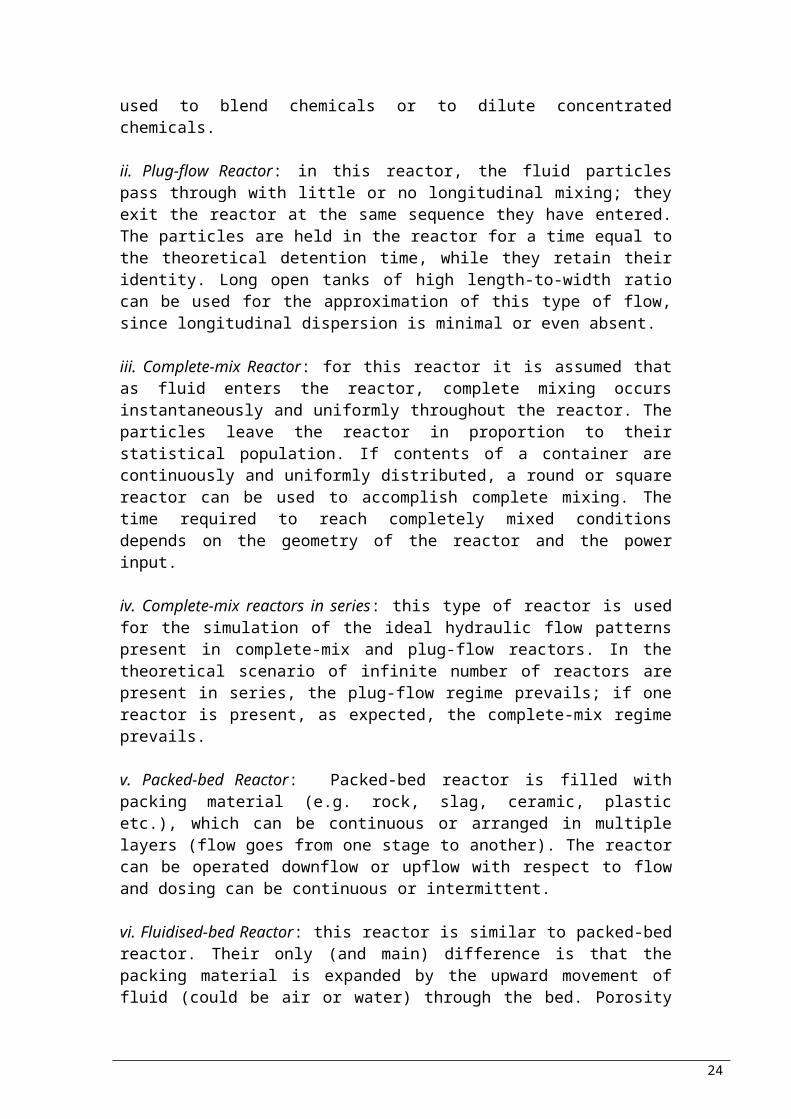
i. Batch Reactor: in a batch reactor no flow is entering or leaving the reactor at the time of the treatment; once flow enters, is treated and discharge. The contents of the reactor are mixed completely. It is thus commonly used to blend chemicals or to dilute concentrated chemicals.
ii. Plug-flow Reactor: in this reactor, the fluid particles pass through with little or no longitudinal mixing; they exit the reactor at the same sequence they have entered. The particles are held in the reactor for a time equal to the theoretical detention time, while they retain their identity. Long open tanks of high length-to-width ratio can be used for the approximation of this type of flow, since longitudinal dispersion is minimal or even absent.
iii. Complete-mix Reactor: for this reactor it is assumed that as fluid enters the reactor, complete mixing occurs instantaneously and uniformly throughout the reactor. The particles leave the reactor in proportion to their statistical population. If contents of a container are continuously and uniformly distributed, a round or square reactor can be used to accomplish complete mixing. The time required to reach completely mixed conditions depends on the geometry of the reactor and the power input.
iv. Complete-mix reactors in series: this type of reactor is used for the simulation of the ideal hydraulic flow patterns present in complete-mix and plug-flow reactors. In the theoretical scenario of infinite number of reactors are present in series, the plug-flow regime prevails; if one reactor is present, as expected, the complete-mix regime prevails.
v. Packed-bed Reactor: Packed-bed reactor is filled with packing material (e.g. rock, slag, ceramic, plastic etc.), which can be continuous or arranged in multiple layers (flow goes from one stage
18
Packing medium
Expanded Packing medium

to another). The reactor can be operated downflow or upflow with respect to flow and dosing can be continuous or intermittent.
vi. Fluidised-bed Reactor: this reactor is similar to packed-bed reactor. Their only (and main) difference is that the packing material is expanded by the upward movement of fluid (could be air or water) through the bed. Porosity of the bed can be altered by changing the flow rate of the fluid.
3b. Flow Regimes
Some of the most common flow regimes used in treatment of wastewater are shown schematically in Figure 4.
i. Direct input with bypass flow (plug-flow or complete-mix reactor): used to achieve intermediate levels of treatment by blending various amounts of treated and untreated. Also, commonly used in design to reduce hazards in case of high flows caused by storms (in case of combined sewage systems).
ii. Direct input with recycle flow (pug-flow or complete-mix reactor): the flow regime of direct input with recycle flow is often adopted to achieve greater process control. Greatly used in biological wastewater treatment.
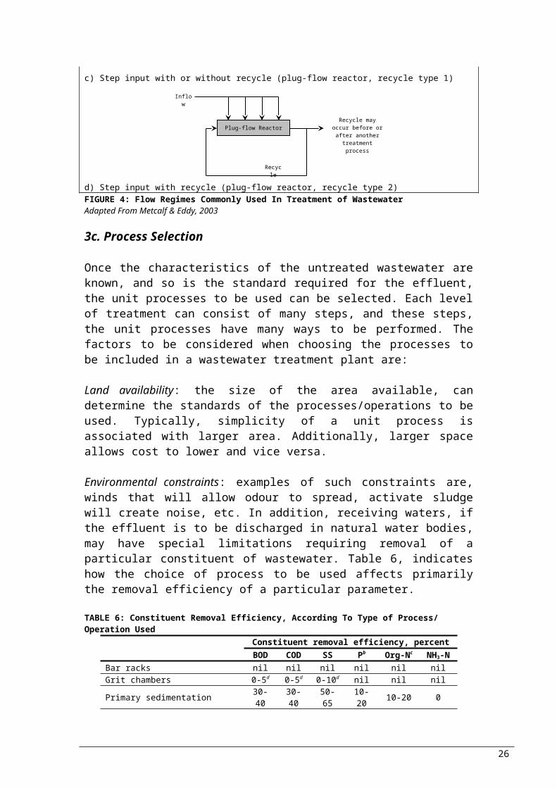
iii. Step input with or without recycle (plug-flow reactor, recycle type 1): primarily used for the reduction of loading applied to a process.
iv. Step input with recycle (plug-flow reactor, recycle type 2): during step input with recycle flow, the return flow is not mixed with the influent, but is introduced at the input of the reactor. The aim is to achieve greater initial dilution of the wastewater to be treated.
a) Direct input with bypass flow (plug-flow or complete-mix reactor)
b) Direct input with recycle flow (pug-flow or complete-mix reactor)
c) Step input with or without recycle (plug-flow reactor, recycle type 1)
19
Reactor
Bypass
Inflow Reactor
Recycle
InflowRecycle may occur
before or after another treatment process
Plug-flow Reactor
Recycle
Inflow
Recycle may occur before or after
another treatment process

d) Step input with recycle (plug-flow reactor, recycle type 2)FIGURE 4: Flow Regimes Commonly Used In Treatment of WastewaterAdapted From Metcalf & Eddy, 2003
3c. Process Selection
Once the characteristics of the untreated wastewater are known, and so is the standard required for the effluent, the unit processes to be used can be selected. Each level of treatment can consist of many steps, and these steps, the unit processes have many ways to be performed. The factors to be considered when choosing the processes to be included in a wastewater treatment plant are:
Land availability: the size of the area available, can determine the standards of the processes/operations to be used. Typically, simplicity of a unit process is associated with larger area. Additionally, larger space allows cost to lower and vice versa.
Environmental constraints: examples of such constraints are, winds that will allow odour to spread, activate sludge will create noise, etc. In addition, receiving waters, if the effluent is to be discharged in natural water bodies, may have special limitations requiring removal of a particular constituent of wastewater. Table 6, indicates how the choice of process to be used affects primarily the removal efficiency of a particular parameter.
TABLE 6: Constituent Removal Efficiency, According To Type of Process/ Operation Used
Constituent removal efficiency, percent
BOD COD SS Pb Org-Nc
NH3-N
Bar racks nil nil nil nil nil nilGrit chambers 0-5d 0-5d 0-10d nil nil nilPrimary sedimentation 30-
4030-40
50-65
10-20 10-20 0
Activated sludge (conventional)
80-95
80-85
80-90
10-25 15-50 8-15
Trickling filter High rate, rock media 65-
8060-80
60-85 8-12 15-50 8-15
Super rate, plastic media 65-85
65-85
65-85 8-12 15-50 8-15
Rotating biological contactors (RBCs)
80-85
80-85
80-85
10-25 15-50 8-15
b P: Total phosphorusc Org-N: Organic Nitrogend the higher numbers apply if grit washers are not used
20
Plug-flow Reactor
Recycle
Inflow
Recycle may occur before or after
another treatment process

Climate: temperature highly important for the efficiency of the processes. To be more accurate, temperature affects the rate of reaction of most of the biological and chemical reactions. Temperature may also affect the physical operation of the facilities. Odour generation and atmospheric emissions are also affected by temperature.
Influent characteristics: characteristic of the wastewater to which the treatment will be applied, affect the types of processes to be used, and the requirements for proper operation.
Effluent standards: the effluent standards required are more detailed explained in the next chapter.
Applicability: process that has to be used according to the contaminants present, and to what amount they are present (Table 6). Typically, past experience is used and where there is no available or the process is new, pilot-plant studies should be used. The processes should also be chosen based on the expected flow rate; processes are usually efficient at particular flow rates. For example, stabilisation ponds should not be used at extremely high flow rates is highly populated areas. Flow variation is also critical when designing a wastewater treatment. Most unit processes/ operations have to be designed to operate over a wide range of flow rates, on contrast to the efficiency of the processes/operations; constant flow rate is required for maximum efficiency.
Performance: complying with the required effluent standards, is the mean by which treatment can be categorised as efficient or not. The variation of the effluent characteristic is also used as way to determine efficiency. Tables like Table 7 could be used for the determination of efficiency of a process for a particular treatment plant. The removal of pathogens present in wastewater is quite substantial in the decision making process.
TABLE 7: Expected Removals of Excreted Microorganisms in Various Wastewater Treatment Systems
Removal in log10 unitsViruse
sBacteri
a Cysts Helminth eggs
Primary sedimentation, plain 0-1 0-1 0-1 0-2Primary sedimentation, coagulated 0-1 1-2 0-1 1-3Activated sludge & secondary sedimentation 0-1 0-2 0-1 0-2Trickling filter & sedimentation 0-1 0-2 0-1 0-2Contact filtration of secondary effluent 0-1 1-2 1-3 1-2Waste stabilisation ponds 1-4 1-6 1-4 1-3Chlorination or ozonation1 0-4 2-6 0-3 0-1Septic tank & anaerobic filter 0-1 0-1 0-1 1-2Upflow anaerobic sludge blanket clarifier 0-1 0-1 1-2 1-2
1 not recommendedSource: Strauss M., 2001
21

Compatibility: in cases where a treatment plant already exists and has to be expanded, compatibility of existing processes/operations has to be taken into consideration
Energy requirements: energy requirement is highly associated with cost, thus it must be known since in most cases, a cost-effective treatment system is one of the optimum choices. Future energy cost should also be taken into account.
Sludge processing/disposal: sludge processing and disposal should be considered at the time the rest of the treatment is designed. For example small plants may not be cost efficient to process sludge on-site.
Complexity: of particular location, e.g. staff availability, if design is converted to automatic safety analysis required; complexity of process to operate under emergency or even routine conditions.
Construction & operational COSTS: cost evaluation must consider initial capital cost and long-term operating and maintenance costs. The plant with the lowest capital cost may not be the most cost efficient in terms of operating and maintenance costs. Typically, costs increase with the level of treatment (Figure 5). A typical cost breakdown is: transport and disposal 2.2%, primary sedimentation 13.2%, secondary sedimentation 9.8%, sludge treatment 33%, biological treatment 41.8%.
FIGURE 5: Relative Capital and Operational Costs of the Main Stages of Processes, Indication of Where Is More Effective To Spend Money, Depending On the % Removal of Pollutants That the Treatment Plant Has A TargetSource: Butler D. and Smith S., 2003
22
Unit costs (capital & operational) cost/m3
% removal of pollutant
PRELIMINARY
PRIMARY
SECONDARY
TERTIARY
BOD 30 50-70 90-95 >95TSS 60 80-90 90-95 >95TN 15 25 40 >80TP 15 75 90 >90

Flexibility: how easily the system could adapt to cases like additional flow, or functioning problem with a unit process/ operation, or how can it be modified for future demand.
Operation & maintenance: provision for spare parts, maintenance or operational requirements. This could be one of the reasons that some processes have become standardised; ease to find equipment for operation and maintenance.
Personnel requirements: associated with number of people required for the proper functioning of the system, level of skill required, possible training that could be required.
Reliability: includes factors such as long term reliability of the choices made for the unit processes/operations, consistency of efficiency (how easily can the process/operation be upset), under what conditions the effluent characteristics will be altered, shock loading cases where some processes are more resistant than others.
TABLE 8: Factors to Be Considered When Choosing Treatment for Wastewater Along With the Efficiency of Some Processes for the Specific Factors
Criterion
Treatment System
Pack
age
Plan
t
Act
ivat
ed
Slud
ge
Bio
logi
cal
Filt
er
Exte
nded
A
erat
ion
Oxi
dati
on
Dit
chA
erat
ion
Lago
onR
BC
Ree
d B
ed
Was
te
stab
ilisa
tion
po
nd (
incl
. W
aste
st
abili
sati
on
pond
(ex
cl.
BOD removal ●● ●● ●● ●●●●●
●●● ●● ●●
●●●
●●●
FC removal ● ● ● ●● ●●●●● ● ●
●●●
●●●
SS removal ●●●●●
●●●
●●●
●●● ●●
●●● ●● ●● ●●
Helmith removal ● ●● ● ● ●● ●● ●●●●
●●●
●●●
Virus removal ● ●● ●● ●● ●●●●● ● ●●
●●●
●●●
Ancillary use possibilities ● ● ● ● ●●●● ●
●●●
●●●
●●●
Effluent re-use possibilities ● al●
al●●
al●● ●●
●●● ● ●●
●●●
●●●
Simple construction ● ● ● ● ●● ●● ● ●●●●●
●●●
Simple operation ● ● ● ● ●● ● ● ●●●●●
●●●
Land requirement ●●●
●●●
●●●
●●●
●●● ●●
●●● ●● ●● ●
Maintenance cost ● ● ● ● ● ● ● ●●●●●
●●●
Energy demand ● ● ● ● ● ● ●●●●●
●●●
●●●
Minimisation of sludge for removal ● ●●
bl●●bl
●●bl ● ●● ● ●● ●●
●●●●
Ability to accept shock ● ●● ● ● ●● ●● ● ●● ●● ●●
23
loads ● ●
● poor ●●fair ●●●goodal The effluents from activated sludge, biological filter and package plants frequently
have high ammonia levels (>5 mg/l) and faecal bacterial concentrations (<106/100ml), and are usually not suitable for irrigation or fish farming without tertiary treatment.
bl Assumes provision of sludge digesters.Source: Butler D. and Smith S., 2003Some of the factors to be considered during the designing of a wastewater treatment plant for the unit processes/ operations can be seen in Table 8. Biological, chemical and physical processes and operations are compared, in addition to “package plant”.
Having considered the most important factors affecting the design of wastewater treatment, in addition to the available options for flow regimes and types of reactions, in the chapter that follows unit processes and operations will be described briefly as introduction to a more detailed description.
24

4. Unit Processes and Operations of Wastewater Treatment
Unit processes and operations should be seen a pieces of a puzzles, needed to build a wastewater treatment plant. Here, a brief description is given on the most important wastewater treatment processes/ operations that can be used for wastewater reclamation/ reuse.
Unit processes are methods of treatment in which the application of physical forces predominate. Unit operations are methods in which the removal of contaminants is achieved by chemical or biological reactions. The unit operations and processes used for the reduction or removal of the most important wastewater constituents are shown in Table 9. Manufacturers could supply units designed for one process to prefabricated package plants incorporating several unit processes. Package plants are most commonly used for small installations, whereas larger are typically custom designed.
TABLE 9: Unit Operations, Unit Processes and Systems Used For Removal/ Reduction Important Parameters in Wastewater
Contaminant Unit operation/ unit process/ treatment systemSuspended Solids (SS) Sedimentation
Screening and comminutionFiltration variationsFlotationChemical-polymer additionCoagulation/sedimentationLand treatment systems
Biodegradable Organics
Activated-sludge variationsFixed-film: trickling filtersFixed-film: rotating biological contactorsLagoon and oxidation pond variationsIntermittent sand filtrationLand treatment systemsPhysical-chemical systems
Pathogens ChlorinationHypochlorinationOzonationLand treatment systems
Nutrients: Nitrogen Suspended-growth nitrification and denitrification
variationsFixed-film nitrification and denitrification variationsAmmonia strippingIon exchangeBreakpoint chlorinationLand treatment systems
Phosphorus Metal-salt additionLime coagulation/sedimentationBiological-chemical phosphorus removalLand treatment systems
Refractory Organics Carbon adsorptionTertiary ozonationLand treatment systems
Heavy Metals Chemical precipitationIon exchange
25
Land treatment systemsDissolved Inorganic Solids
Ion exchangeReverse osmosisLand treatment systems
Sources: Metcalf & Eddy, 2003
The unit processes and operations that could be included in a wastewater treatment plant are listed alphabetically below, with some comments. Each process will be described in detail in the chapters that will follow, according to the level of treatment (i.e. preliminary, primary, secondary, tertiary, or advanced) it is part of.
Activated Carbon Treatment: Activated carbon is used for the adsorption of toxic substances such as metals and pesticides; may be added to biological treatment or used as treatment by itself.
Air Flotation: Air flotation is used for the separation of suspended matter from wastewater. Its’ primary use is the thickening of biological or chemical sludge suspensions.
Aerobic Biological Treatment: mainly used for the removal of dissolved and suspended organics. There are many processes available for the treatment. During this process, air (oxygen) is supplied to microorganisms that are in contact with the wastewater. As they metabolise the organic material into carbon dioxide, other end products and new biomass, the putrescibility and BOD are reduced.- Trickling Filters- Biodisks (Rotating biological contactors)- Activated Sludge: this is a suspended growth process where
microorganisms are mixed with the wastewater. The oxygen is supplied through pumping of air, which also allows mixing; pure oxygen could be supplied, but additional mixing would be required. The variations of the process are numerous.
The processes could be altered to allow the removal of nitrogen, oxidation of nitrogen and removal of phosphorus. Aerobic biological treatment must be followed by sedimentation where the solids created are physically removed (if solids are left to degrade in biological treatment is more expensive).
Air Strippers: used for the removal of volatile compounds or gases. These devices are enhancing mass transfer between liquid and the atmosphere, by increasing the surface area of the liquid for maximum exposure to the atmosphere. Examples of types of stripping devices are counter-current flow and diffused aeration systems.
Ammonia Stripping: formation of ammonia is favoured at high pH. Once it is formed (ammonia is a volatile gas), air strippers are used for the removal of the deionised ammonia.
26

Anaerobic Biological Treatment: when anaerobic microorganisms come in contact with wastewater, dissolved and suspended organic mater is converted to biomass and methane. Similarly to the aerobic treatment, in some processes the microorganisms are supported on solid support media (fixed film process -e.g. anaerobic filters, fluidised beds-) whereas in others are kept in suspension. Often, anaerobic digesters are used after aerobic treatment and primary clarifiers for the treatment of the solids produced, since the volume of the solids is reduced considerably.
Chemical Feed Mixers: devices designed to disperse chemicals fast and well throughout the fluid. Well used in physical, chemical and biological processes.
Coagulation: this is the process by which colloidal particles are stabilised by the addition of chemicals in a mixing device. This allows agglomeration/ flocculation with other suspended particles for the formation of larger and easier to settle particles. The occurring reactions are rapid; dispersion is essential, since he chemical added could be consumed by reactions with water.
Comminutors: devices used for the maceration of rags, sticks, paper and other large solid objects; placed downstream of the grit chamber.
Disinfection: prior discharge, clarified effluent has to be disinfected for the reduction of pathogens. Most commonly used are chlorine and UV. The type of chamber used for the disinfectant-wastewater contact is plug-flow
Equalisation: these are holding tanks where wastewater is held when variations in flow quantity and quality are significant.
Filtration: commonly used for the removal of colloidal or solid particles which do not settle in the sedimentation basin. Also used after the clarifiers to “polish” the effluent.
Flocculation: by the application of gentle agitation of coagulated water, particles are promoted for more contact, and thus the formation of larger particles. Flocculators could be hydraulic or mechanical; follow rapid mixing (coagulation) and precede sedimentation and filtration.
Grit Chambers: these are sedimentation basins designed for the removal of nonputrescible matter (silt, sand). This matter is non biodegratable, so it has to be collected. A type of chamber allows water circulation to keep lighter particulates in suspension while the heavier settle.
27

Lagoons: mechanically aerated ponds which allow aerobic biological treatment.
Membranes: allow reverse osmosis and electrodialysis, which are applied for the recovery and removal of particular species.
Neutralization: wastes with extremely high or low pH (industrial wastewater) are neutralized by the addition of acid or base. Particularly important for biological treatment that pH has to be near neutral.
Oxidation ditches : this is an oval channel with mechanical aeration for the provision of aerobic biological treatment.
Pipes, channels, other conduits: flow of minimum velocity 0.6-0.9 m/s required for avoidance of deposition of solids (WEF & ASCE, 1992).
Recarbonation: addition of CO2 for the neutralization of excess OH-
being added for coagulation-flocculation.
Screens & Bar Racks: used for the removal of coarse debris. Bar racks are located at the intakes to wet wells the inlet of the wastewater treatment plant. Screens are situated after the bar racks. Typically material collected is non-biodegradable and have to be collected for treatment.
Sedimentation: primary clarifiers – designed for the removal of settlable solids before biological treatment of dissolved organics. Secondary clarifiers follow the biological treatment for the removal of biomass formed during biological treatment and partial thickening of accumulated sludge. In a physico-chemical treatment plant, clarifiers are located after coagulation and flocculation.
Sludge Concentration & Dewatering: performed mainly for the reduction of volume. For the removal of water vacuum dewatering, drying beds, filter press and centrifugation are some of the processes used. Improvement of dewatering efficiency is achieved by addition of chemicals.
Sludge Digestion: reduction of sludge volume and quantity by aerobic or anaerobic microbial action.
Sludge Thickening: this is a settling process where sludge is concentrated at the basin by gravity. High concentrations of colloidal and suspended matter can be found in the supernatant, which is returned back to primary clarifier.
28

Stabilisation Ponds: these are ponds in series where wastewater is settled and biologically treated. Effluent suspended solids could be removed by a final treatment or a screen. Where fish are allowed to grow and harvest in the later in the series ponds, the system is referred to as aquaculture.
Ultrafiltration/ nanofiltration/ microfiltration: used for filtration and recovery of compounds in wastewater.
Figure 7, gives a good summary of the components that a level of treatment could be considered of; or a categorisation of the unit processes used for treatment of wastewater, according to Butler & Smith (2003), whereas Figure 6, an example of a treatment process train that could be used for wastewater reuse. It could also be seen as a flow diagram of wastewater through the treatment, and if any waste is produced from the processes. It should be noted that in some books, preliminary treatment is considered as a treatment level by itself. In others though (Figure 7), preliminary treatment is considered to be part of preliminary treatment.
In the chapters that follow, unit processes used for preliminary, primary, secondary and tertiary treatment will be described in more detail (table 10). In addition to the processes, a description of the available options for components needed for many processes/ operations of the treatment train is given in one of the last chapters; e.g. mixing devices and chemical feeders.
29

FIGURE 6: Typical Municipal Wastewater Treatment FacilitySource: Zytner G.R., 2004
30
TREATMENT PROCESS TREATMENT UNIT PRODUCT PRODUCT DISPOSALP
RIM
AR
Y T
RE
ATM
EN
T
Pre
limin
ary
treat
men
tRaw wastewater
Mechanical separation
Racks Screens Commin
utors
Screenings Burial Maceration and
return to flow Incineration
Mechanical separation (small inorganic
solids)
Grit chambers Grit Burial or landfill
Mechanical separation (light putrescible,
largely organic solids) Primary
sedimentations tanks
Raw sludge
SE
CO
ND
AR
Y T
RE
ATM
EN
T
Biological treatment (usually aerobic
biological oxidation)
Tric
klin
g fil
ters
Rot
atin
g b
iolo
gica
l
Act
ivat
ed s
ludg
e
Oxi
datio
n po
nds
Oth
er s
ludg
e tre
atm
ent
& d
ispo
sal
Hum
us ta
nks
Hum
us ta
nks
Fina
l set
tling
Mechanical separation (biological solids)
Ana
erob
ic d
iges
tion
De-
wat
erin
gLa
ndfil
l
Biological sludge
TER
TIA
RY
TR
EA
T.
PhysicalChemicalBiological
FiltrationBackwash water Return to plant
influentDisinfection
Tertiary ponds
Land filtrationGrass filtration
Vegetation growth Animal grazing or mowing
AW
T
Physical or Chemical or
Biological
Nutrient removal
SludgeSludge disposal
Removal of dissolved organics
Activated carbon Re-use or disposal
▪ DesaltingWaste brines
Disposal
TREATED EFFLUENT DISPOSAL OR RE-USE
FIGURE 7: Unit Operations and Unit Processes of Which the Treatment Levels Are ComposedSource: Butler D. And Smith S., 2003
31

TABLE 10: Unit Processes/ Operations to Be Described In This Project, For Respective Treatment
Unit Processes Available OptionsA5
. Pre
limin
ary
Coarse Solids Reduction Coarse Screens Manually cleanedMechanically cleaned
ComminutorsMaceratorsGrinders
Grit Removal Horizontal flow grit chambers
Aerated grit chambersVortex type grit chambers
Flow Equalisation
A6. P
rim
ary
Settling/ Sedimentation Basins
Rectangular tanks Chain-and-flight collectorTravelling-bridge type collector
Circular tanks Centre feedPeripheral feed
High-rate Clarification Microsand ballasted flocculation and clarification
Chemical addition, multistage flocculation, and lamella clarification
Two-stage flocculation with chemically conditioned recycled sludge followed by lamella clarification
Flotation Dissolved air flotationDispersed air flotation
A7. S
econ
dary
Tre
atm
ent
Activated Sludge (AS) Conventional ASStep-feed ASContact stabilisation ASCompletely mixed ASExtended aeration ASHigh-purity ASSelector ASSequencing Batch Reactor
ASTrickling FiltersRotating Biological ContactorLagoons Aerobic
Facultative & facultative aerated
AnaerobicAnaerobic Biological
ProcessesAnaerobic DigestionLow-Rate Anaerobic
ProcessesHigh-Rate Anaerobic
ProcessesAnaerobic contactUpflow Anaerobic sludge Blanket
Anaerobic filtersHybrid upflow anaerobic sludge blanket and anaerobic filters
Fluidised bed/ expanded bedSolids Fermentation
A8. T
ertia
ry
Nutrient Removal: Nitrogen NitrificationDenitrification
Nutrient Removal: Phosphorus
BiologicalChemical precipitation
Disinfection ChlorineChlorine DioxideOzoneUltraviolet Radiation
A9.
Adva
nced
Membrane Filtration MicrofiltrationUltrafiltrationNanofiltrationReverse osmosisDialysisElectrodialysis
32

Carbon Adsorption Granular Activated Carbon Fixed BedExpanded Bed
Powdered Activated CarbonA1
0. a
dditi
onal
com
pone
nts
Chemical feeders Dry chemical-feed systemLiquid chemical-feed systemGas chemical-feed system
Mixers Mixing & blending devices Static in-line mixersIn-line mixersHigh-speed induction mixersPressurised water jetsTurbine and propeller mixersPumpsOther hydraulic devices
Flocculation devices Static mixersPaddle mixersTurbine mixers
Continuous mixing Mechanical aeratorsPneumatic mixing
pH neutralisation Sodium Hydroxide & Sodium Carbonate
LimeLimestone And Dolomitic
Limestone
A11.
Slu
dge
Trea
tmen
t
Conditioning Chemical Inorganic agentsOrganic agents
Physical ThermalFreeze-thawHigh energy application
Thickening Gravity thickeningGravity belt thickenersDissolved air flotationCentrifuges Rotary drums
Dewatering Drying bedCentrifugingFilter bedFilter pressReed bedsDrying lagoons
Stabilisation/Disinfection Aerobic digestionAnaerobic digestion
(methanisation)Long-term storageCompostingAlkaline stabilisationNon-alkaline stabilisationPasteurisationIrradiation
Heat Drying
33

5. Preliminary Treatment
Preliminary wastewater treatment is the first step of a wastewater treatment plant, consisting of coarse solids reduction and grit removal, and flow equalisation (if is needed).
5a. Coarse Solids Reduction
Coarse solids reduction is achieved by the use of screens, or comminutors, macerators and grinders. These have the advantage over screening, of eliminating the need for handling and disposing screenings.
i. Screening
Screens have a wide range of application, due to the variety of devices available (Figure 8). At this stage of treatment the type of screens used are coarse screens, whereas other types can be found at other point in the treatment.
Screening
Coarse screens
6-150mm
Microscreens <50μm
Fine screens <6mm
Manually cleaned
Mechanically cleaned
Static wedgewire
Drum Step
Chain-driven Reciprocating rake
Catenary Continuous belt
FIGURE 8: Definition Sketch for Types of Screens Used In Wastewater TreatmentSource: Metcalf & Eddy, 2003
The screening element can consist of parallel bars, rods or wires, grating, wire mesh, or perforated plate. The openings may be of any shape, but circular or rectangular are the ones most commonly used for wastewater treatment. The types of coarse screens most commonly used for wastewater treatment are shown in Table 11.
TABLE 11: Description of Coarse ScreensScreen Type DescriptionTrash Rack Opening size 38 to 150 mm. Designed to prevent logs, timbers,
stumps, and other large debris from entering treatment processes.
Manually Cleaned Coarse Screen
Opening size: 30 to 50 mm. Designed to remove large solids, rags, and debris. Bars set at 30 to 45 degrees from vertical to facilitate cleaning.Primarily used in older or smaller treatment facilities, or in bypass channels.
Mechanically Cleaned Coarse
Opening size 6 to 38 mm. Designed to remove large solids, rags, and debris. Bars set at 0 to 30 degrees from vertical. Almost
34

Screen always used in new installations because of large number of advantages relative to other screens.
Source: WEF & ASCE, 1998
Manually Cleaned Coarse Screens: most commonly used ahead of pumps in small wastewater pumping stations; sometimes used at headworks of small-medium sized wastewater treatment plants; often used for standby screening in bypass channels for service in high flow periods, when mechanically screens cleaned and in case of power failure.
Mechanically Cleaned Coarse Screens: divided into four principal types, (1) chain-driven, (2) reciprocating rake, (3) catenary and (4) continuous belt. The advantages and disadvantages of each are listed in the table that follows (Table 12).
TABLE 12: Advantages & Disadvantages of Various Types of Coarse ScreensScreen Type Advantages DisadvantagesChain-driven screen
- front-clean/ back return
▪ Multiple cleaning elements (short cleaning cycle)
▪ Unit has submerged moving parts that require channel dewatering for maintenance
▪ Used for heavy-duty applications
▪ Less efficient screenings removal, i.e. carryover of residual screenings to screened wastewater channel
- front-clean/ front turn
▪ Multiple cleaning elements (short cleaning cycle)
▪ Unit has submerged moving parts that require channel dewatering for maintenance
▪ Very little screenings carryover ▪ Submerged moving parts (chains, sprockets, shafts) are subject to fouling.▪ Heavy objects may cause rake to jam
- back clean/ back return
▪ Multiple cleaning elements (short cleaning cycle)
▪ Unit has submerged moving parts that require channel dewatering for maintenance
▪ Submerged moving parts (chains, sprockets, shafts) are protected by bar rack
▪ Long rake teeth are susceptible to breakage
▪ Some susceptibility to screenings carryover
Reciprocating rake
▪ No submerged moving parts; maintenance and repairs can be done above operating floor
▪ Unaccounted for high channel water level can submerge rake motor and cause motor burn out
▪ Can handle large objects (eg.bricks, tires)
▪ Requires more headroom than other screens
▪ Effective raking of screenings and efficient discharge of screenings
▪ Long cycle time; raking capacity may be limiting
▪ Relatively low operating and maintenance costs
▪ Grit accumulation in front of bar may impede rake movement
▪ Stainless-steel construction reduces corrosion
▪ Relatively high cost due to stainless-steel construction
▪ High flow capacityCatenary ▪ Sprockets are not submerged;
most maintenance can be done above the operating floor
▪ Because design relies on weight of chain for engagement of rakes with bars, chains are very heavy and difficult to handle
▪ Required headroom is ▪ Because of angle of inclination
35
relatively low of the screen (45 to 75˚) screen has a large footprint
▪ Multiple cleaning elements (short cleaning cycle)
▪ Misalignment and warpage can occur when rakes are jammed
▪ Can handle large objects ▪ May emit odours because of open design
▪ Very little screening carry-overContinuous belt ▪ Most maintenance can be done
above operating floor▪ Overhaul or replacement of the screening elements is a time-consuming and expensive operation
▪ Unit is difficult to jamSource: Metcalf & Eddy, 2003
ii. Comminutors
Comminutors are primarily used at small treatment facilities; i.e. less than 0.2 m3/s to process material between 6 and 19 mm (WEF, 1998). Shredded material remains in the wastewater and is removed in downstream treatment processes. A typical communitor uses a stationary horizontal screen for intercepting the flow, and a rotating or oscillating arm meshing with the screen, that contains cutting teeth. The cutting teeth and the shear bars cut coarse material. There is the possibility with communitors, of a string of material (rags) to be created that has be collected further downstream. Newer installations use a screen or a macerator, to avoid the operating problems and the high maintenance required.
iii. Macerators
These are slow-speed grinders. Macerators can be used in pipeline installations for the shredding of solids; particularly ahead of wastewater and sludge pumps, or in channels at smaller wastewater treatment plants.
There are two types of macerators:a. Two counterrotating blade assemblies, mounted vertically to the
flow channel. The blades or teeth on the rotating assemblies have a close tolerance effectively chopping material as it passes through. Sizes of pipeline applications typically range from 100 to 400 mm in diameter.
b. A moving linked screen allowing wastewater to pass through the screen while diverting screenings to a grinder located at one side of the channel. This type is mainly used in channel applications. Standard sizes of this device are available for use in large channels from widths 750 to 1800 mm and depths of 750 to 2500 mm. The headloss is lower than that of the units with counterrotating blades.
iv. Grinders
36

Typically referred to as hammermills, these are high-speed grinders that receive screened materials from bar screens. The materials are pulverised by a high-speed rotating assembly that cuts the materials passing through the unit. The screenings are sorced by the blades through a stationary grid or louver that encloses the rotating assembly. The washwater is typically used to keep the unit clean and to help the transportation of material back into the wastewater stream. Discharge from the grinder can be located either upstream or downstream of the bar screen.
5b. Grit Removal
Grit is defined as sand, gravel, or other mineral matter having the nominal diameter of 0.15-0.20 mm or larger. Estimated grit quantities in wastewater are 0.004-0.037m3/1000m3 wastewater for separate systems and 0.004-0.18m3/1000m3 wastewater for combined (WEF & ASCE, 1992). Typically, grit chambers are designed to remove all particles with nominal diameter of 0.20 mm or larger; i.e. solid materials having subsiding velocities or specific gravities significantly greater than those of organic putrescible solids in wastewater.
The most common location of grit chambers is after bar screens, which makes the maintenance and the operation of the grit removal facilities easier; and before primary sedimentation tanks where the heavy organic solids are removed. In addition, the removal of grit is essential ahead of centrifuges, heat exchangers and high-pressure diaphragm pumps. Grit chambers are used for the (1) protection of mechanical equipment from abrasion and consequently abnormal wear, (2) reduction in formation of heavy deposits in pipelines, channels and conduits, and (3) reduction in digester cleaning frequency caused by excessive accumulation of grit.
The types of grit chambers are 3: horizontal or rectangular horizontal flow, aerated, and vortex.
i. Horizontal Flow Grit Chambers
Rectangular horizontal flow velocity controlled grit chambers are designed to maintain velocity at 0.3 m/s and to provide sufficient time for the settling of the grit particles, while organic particles are in suspension. The length of the channel depends on the depth required by settling velocity; the cross-sectional area depends on the rate of flow and the number of channels. The removal of grit is achieved by a conveyor with scrapers, buckets or plows. In small plants, manual cleaning of the chambers is also used.
37

A series of vanes or gates distributes the influent to the units over the cross section of the square tank. The distributed wastewater flows in straight lines across the tank and overflows a weir in a free discharge. This type of grit chambers are designed on the basis of overflow rates, which depend on the particle size and temperature of the wastewater: typically removal of 95% of 0.15 mm diameter particles at peak flow. Solids are removed by a rotating raking mechanism to a sump on the side of the tank. Table 13 shows typical design data for horizontal flow grit chambers.
TABLE 13: Typical Design Data for Horizontal Flow Grit ChambersRange Typical
Detention time (s) 45-90 60Horizontal velocity (m/s) 0.25-0.4 0.3Settling velocity for (m/mina)
0.21mm material 1.0-1.3 1.150.15mm material 0.6-0.9 0.75
Headloss in control section as % of channel depth (%) 30-40 36b
Added length allowance for inlet and outlet turbulence (%) 25-50 40
a if the specific gravity of the grit is significantly less than 2.65, lower velocities should be usedb for Parshall flume controlSource: Metcalf & Eddy, 2003
ii. Aerated Grit Chambers
As wastewater moves through the tank air is supplied from a diffuser located on the one side of the tank, inducing a spiral flow pattern perpendicular to the tank. The roll velocity should sufficient for the light (principally) organic particles to stay in suspension and the heavier to settle; in case that the velocity is too high, grit will be carried out of the chamber; if is too low, organic material will be removed with the grit. The device however is flexible, due to the easy adjustment of the air supply. The nominal design of aerated grit chambers removes particles of diameter 0.21 mm or larger, at 2-5 minutes detention times at peak hourly rate of flow. The typical design parameters used for aerated grit chambers are shown in Table 14. Grit is removed by grab buckets travelling on monorails and centred over the grit collection and storage trough.
TABLE 14: Typical design data for aerated grit chambersRange Typical
Detention time at peak flow rate (min) 2 - 5 3Depth (m) 2 - 5Length (m) 7.5 - 20Width (m) 2.5 - 7Width-depth ratio 1:1 – 5:1 1.5:1Length-width ratio 3:1 – 5:1 4:1Air supply per unit length (m3/m min) 0.2 – 0.5Grit quantities (m3/1000m3) 0.004 - 0.2 0.015
Source: Metcalf & Eddy, 2003
38

iii. Vortex-type Grit Chambers
Another type of grit chamber used is vortex-type. Constant speed of flow is induced into the chamber by a turbine. Grit is separated from the organics by adjustable blades. The existing designs are two: chambers with flat bottoms and a small opening to collect grit; and chambers with a sloping bottom and a large opening into the grit hopper. The flow into the system should be straight, smooth and streamline.
The inlet length of the channel typically used is seven times the width of the inlet channel, or 4.6 m, whichever is greater. The ideal velocity range in the influent is typically 0.6 to 0.9 m/s at 40-80 % of peak flow. Minimum velocity of 0.15 m/s should be maintained at all times, because lower velocities will not carry grit into the grit chamber (WEF, 1998).
5c. Flow Equalisation
Influent wastewater into a wastewater treatment plant has variations in flow rate and characteristics. In cases where the conditions are extreme and the efficiency of the treatment would be greatly affected, flow equalisation is used. In most cases, the flow equalisation basin is located after screening and grit removal, and before primary sedimentation.
Through flow equalisation, hydraulic velocity or flow rate is controlled through a wastewater treatment system. Short term, high volumes of incoming flow, called surges, can be prevented, by equalisation of flow preventing solids and organic material to be forced out of the treatment process. Flow equalisation also controls the flow through each stage of the treatment system, allowing adequate time for the physical, biological and chemical processes to take place.The main objective of flow equalisation basins is to dampen the diurnal flow variation, as well as variations caused by inflow/infiltration, and thus achieving a nearly constant flow rate through the downstream treatment processes. There are cases though, where equalisation is used to dampen the strength of wastewater constituents by blending the wastewater in the equalisation basin to maintain a degree of reliability and operational control. Equalisation basins should be located downstream of pre-treatment facilities (bar screens, comminutors, grit chambers) and where possible, primary clarifiers.
The basins can be designed as in-line or side-line units. In the in-line arrangement, all of the flow passes through the basin. This arrangement is used where considerable amount of constituent concentration has to be achieved, and flowrate has to be damped.
39

In the off-line arrangement, only flow exceeding a predetermined limit is diverted into the basin. With this arrangement, pumping requirements are minimised, the amount of constituent concentration damping is reduced considerably. Off-line equalisation is commonly used for the capture of the “first flush” from combined collections systems. The principal factors to be considered while designing an equalisation basin are basin geometry and construction, mixing and air requirements, operational appurtenances, and pumps and pump control.
The main advantages of using flow equalisation are:1. Enhancement of biological treatment: shock loadings are
minimised, inhibiting substances can be diluted and pH stabilised.
2. Improvement of performance of secondary sedimentation tanks (following biological treatment) because of improved consistency in solids loading.
3. Improvement of filter performance, reduction in requirement for effluent filtration surface area and more uniform filter-backwash cycles, due to lower hydraulic loading.
4. Improvement of chemical feed control in chemical treatment and process reliability due to reduction in mass loading.
5. Improvement of efficiency for overloaded treatment plants.
And the main disadvantages:1. Need for relatively large land areas.2. Where plants are situated near residential areas, facilities of
equalisation may have to be covered for odour control.3. Additional operation and maintenance.4. Increase of capital cost.
The next step after preliminary treatment is primary treatment.
40

6. Primary Treatment
Primary treatment is associated with some reduction of suspended solids and organic matter in wastewater. This level of treatment can be and is being used with disinfection as complete treatment plant. However the quality of the effluent is not suitable for wastewater reuse. Reduction of suspended solids and organic matter in wastewater can be achieved by sedimentation (6a) or flotation (6b).
6a. Sedimentation BasinsSedimentation is also used in secondary treatment, following the biological treatment.
Sedimentation (also known as settling or clarification) is used for the removal of readily settleable solids and floating material (e.g. oil and grease). Well designed and operated sedimentation tanks, are able to reach 50-70% suspended solids removal, and 25-40% BOD removal.
Sedimentation tanks currently used are almost all mechanically cleaned. They could be circular or rectangular. The selection of the type to be used depends on the size of the installation, local regulations, site characteristics and experience of the engineer. At large plants, the number of basins depends primarily on size limitations (land availability).
i. Rectangular Tanks
The solids collectors that can be used for rectangular tanks are chain-and-flight or travelling-bridge type collectors. A pair of alloy steel, cast iron or thermoplastic endless conveyor chains is the equipment used for the removal of settled solids. Wooden or fibreglass scraper flights are attached to the chains at about 3 m intervals, extending the full width of the tank. In small tanks, the solids are scraped to solid hoppers and to transverse troughs in large tanks. The solids are transferred to the solid hoppers or transverse troughs by cross collectors, typically chain-and-flight or screw-type.
Bridge-type collector can also be used for cleaning of a rectangular tank, travelling up and down the tank on rails supported on the sidewalls or rubber wheels.
Multiple solids hoppers must be installed where cross collectors are not provided. Operational problems associated with solids hoppers are solids accumulation on slopes and corners, and arching over the solids drawoff piping. Another problem is the rathole effect; wastewater drawn through the solids hopper, while
41

some accumulated solids are bypassed. Consequently, a cross selector is more advisable, since solids collected are more uniform and concentrated whereas the problems associated with the solids hopper are eliminated.
Typical designing information for primary rectangular basins is given in table 15.
TABLE 15: Typical Design Information for Primary Sedimentation TanksRange Typical
PRIMARY SEDIMENTATION TANKS FOLLOWED BY SECONDARY TREATMENT
Detention time (hrs) 1.5 – 2.5 2Overflow rate at Average flow (m3/m2d ) 30 – 50 40 Peak hourly flow (m3/m2d) 80 – 120 100Weir Loading (m3/m d ) 125 – 500 250
PRIMARY SETTLING WITH WASTE ACTIVATED-SLUDGE RETURNDetention time (hrs) 1.5 – 2.5 2Overflow rate at Average flow (m3/m2d ) 24 – 32 28 Peak hourly flow (m3/m2d) 48 – 70 60Weir Loading (m3/m d ) 125 – 500 250
RECTANGULAR TANK FOR PRIMARY TREATMENTDepth (m) 3 – 4.9 43Length (m) 15 – 90 24 – 40Width (m) 3 – 24 4.9 – 9.8Flight speed (m/min) 0.6 – 1.2 0.9
CIRCULAR TANK FOR PRIMARY TREATMENTDepth (m) 3 – 4.9 4.3Diameter (m) 3 – 60 12 – 45Bottom slope (mm/mm) 1/16 – 1/6 1/12Flight speed (r/min) 0.02 – 0.05 0.03
Source: Metcalf & Eddy, 2003
Due to the importance of flow distribution in rectangular basins, the inlet designs that should be used are: Full-width inlet channels with inlet weirs: inlet weirs are
effective in spreading flow across the width of the tank, but introduce a vertical velocity component in the solids hopper, that could cause re-suspension of the solid particles.
Inlet channels with submerged ports or orifices: Good distribution across the tank width can be provided by inlet ports, if velocities are maintained at 3 – 9 m/min.
Inlet channels with wide gates and slotted baffles: inlet baffles are effective in the reduction of high initial velocities and the distribution of flow over the widest possible cross-sectional area. In cases where full-width baffles are used, they should be 150 mm below the surface to 300 mm below the entrance opening.
Scum collectionTypically, collection of the scum takes place at the effluent end with flights returning at the liquid surface. Before removal, baffles trap the scum as it is moved by the flights. Another method for
42
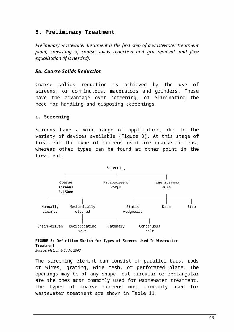
moving scum is water sprays. Scraping of scum can be manually (inclined apron), hydraulically or mechanically.
Scum removalScum removal in rectangular sedimentation basins can be achieved by several methods: For small installations, a horizontal, slotted pipe rotated by a
lever or screw is used for scum drawoff. When the open slot is drawing scum, it is submerged right below the water level permitting the accumulated scum to flow into the pipe, whereas when is not drawing scum, it is above the water level. The result of using this method is large volumes of scum.
A transverse rotating helical wiper attached to a shaft: after scum has been removed from water surface, it is moved over a short inclined apron to a cross-collecting scum trough. The scum is then flushed to a scum ejector or hopper ahead of a scum pump.
Chain-and-flight type collector: the scum is collected at one side of the tank and then being scraped up a short incline to be deposited in scum hoppers.
Special scum rakes: in tanks equipped with carriage or bridge type
Hoppers are usually equipped with mixers in cases when the scum collected is of significant volumes, to provide pumping with homogeneous mixture. Even though some plants treat scum separately, typically is collected and treated in the same manner as solids and biosolids.
Applications Require less space than circular in cases of multiple tanks: used
where space is limited; Nesting with pre-aeration tanks and aeration tanks in activated
sludge, resulting to reduction of construction cost; Usually chosen when tank roofs or covers are required.
ii. Circular Tanks
Flow in circular tanks follows a radial pattern. Consequently, the influent to the unit has to be introduced in the centre or around the peripheral of the tank. Regardless that the efficiency of the two is the same, the centre-feed being most commonly used for primary clarifiers and peripheral-feed for secondary clarifiers (typical design parameters for circular tanks are shown in table 15).
Centre-feedA pipe suspended from the bridge, or encased in concrete beneath the tank floor, transfers the wastewater to the centre of the tank,
43
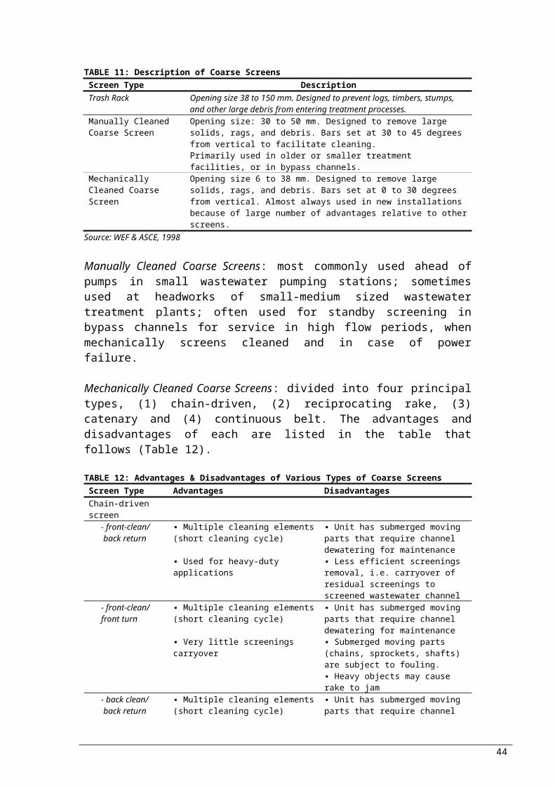
where is distributed equally in all directions via a circular well. Typical dimensions of the well are 1-2.5 m depth and diameter of 15-20% of total tank diameter. The energy-dissipating inlet within the feedwell should be tangential.
Energy dissipating device: The influent is collected from the centre column and discharged tangentially into the upper 0.5 – 0.7 m of the feewell by the energy dissipating device.Velocity: ≤ 0.75 m/s at maximum flow and 0.3 – 0.45 m/s at average flow, produced by correctly sized discharge ports.Feedwell: the size of the feedwell should be appropriately designed so 0.75 m/s of maximum downward velocity is not exceeded; its depth should go 1 m below the energy-dissipating inlet ports (Randall et al., 1992)
Peripheral feedAn annular space into which inlet wastewater is discharged in a tangential direction, is formed by a suspended circular baffle. The clarified liquid is skimmed off over the weirs on both sides of a centrally located weir trough, as the wastewater flows spirally around the tank and under the baffle. Scum and grease are restrained to the surface of the annular space.
Removal equipmentThe way solid removal equipment is supported within the tank, differs according to the size of the tank: Diameter 3.6 – 9 m: supported on beams spanning the tank; Diameter ≥ 10.5 m: supported by central pier, reached by a
walkway or bridge.A small hopper near the centre of the tank is where the solids are scraped to. Groups of two or four are used for the arrangement of multiple tanks, whereas the flow to the tanks is divided by a flow-split structure between the tanks. Sludge pumps are commonly used for the withdrawing of the solids, which are sent to the solids treatment.
Performance
Factors reducing the efficiency by which BOD and TSS are removed are:
1. eddy currents formed by inertia of incoming fluid;2. wind induced circulation cells (uncovered tanks);3. thermal conversion currents;4. cold or warm water causing formation of density currents
moving along the bottom of the basin and warm water rising and flowing across the top of the tank;
5. thermal stratification in hot arid climates
Important Design Considerations
44

- Detention time- Surface loading rates- Weir loading rates- scour velocity- Characteristics and quantities of scum
High-Rate Clarification
Physicochemical treatment is employed for high-rate clarification, whereas special flocculation and sedimentation systems are utilised for the achievement of rapid settling. The enhanced particle settling and the use of inclined plate or tube settlers are the essential elements. Table 16 summarises the processes’ features of high-rate clarification.
Advantages1. compact units, reducing space requirements;2. rapid start-up times for peak efficient, typically less than 30
minutes;3. production of a highly clarified effluent
TABLE 16: Summary of Features of High-Rate Clarification ProcessesProcess FeaturesMicrosand ballasted flocculation and clarification
microsand provides nuclei for floc formation dense, settling rapidly floc lamella clarification, when used, provides high-rate settling in a small tank volume
Chemical addition, multistage flocculation, and lamella clarification
three-stage flocculation enhances floc formation lamella clarification provides high-rate settling in a small tank volume
Two-stage flocculation with chemically conditioned recycled sludge followed by lamella clarification
settled sludge solids are recycled to accelerate flow formation
dense, settling rapidly floc lamella clarification provides high-rate settling in a small tank volume
Source: Metcalf & Eddy, 2003
6b. Flotation
The separation of solid or liquid particles from liquid phase can be accomplished by flotation. The separation is achieved by the introduction of a fine gas (usually air) bubbles to the liquid phase. Particles are raised to the surface (even large or dense, very small or low density), by being attached to bubbles; the buoyant force increases by the particle and bubble/s attachment.
The application of flotation in wastewater treatment removes suspended matter and concentrates biosolids. The main advantage
45

of flotation is that more small or light particles can be removed and faster, in comparison to sedimentation whose settling is very slow.
Air bubbles are added or caused to form by two methods, dissolved air and dispersed air flotation. Efficiency is commonly improved by addition of chemicals.
i. Dissolved air flotation
Under the pressure of several atmospheres, air dissolves in the wastewater, followed by release of pressure to atmospheric level. Small systems: pumps of 275-350 kPa provide sufficient
pressure for the pressurisation of the entire flow. Air dissolves during several minutes that the entire flow is held in a retention tank. The air comes out of the solution in very fine bubbles, as it admitted through a pressure reducing valve.
Larger systems: a portion of the effluent from dissolved air flotation (15-20%) is recycled, pressurised and semi-saturated with air. Just before the main stream enters the flotation tank, the recycled portion is added. The result, is that air comes in contact with the wastewater at the entrance of the tank and not in the tank.
ii. Dispersed air flotation
Rarely used by municipal treatment plants, this method is common in industry, for the removal of emulsified oil and suspended solids from high volume wastes or process water.
A revolving impeller introduces gas phase directly into the liquid phase, causing formation of bubbles. The impeller also acts as pump, by forcing the liquid through dispersed openings thus creating a vacuum in the standpipe. The vacuum consequently pulls air in the standpipe, mixing thoroughly the liquid. Before the liquid leaves the unit, it is passed through a series of cells. Particles of oil and suspended solids form a dense froth on the surface and removed by skimming paddles. The advantages and disadvantages associated with the method are shown in table 17. Quantities of float skimmings are considerably higher (3-7%) than dissolved air flotation (<1%).
TABLE 17: Advantages and disadvantages of dispersed-air flotationAdvantages Disadvantages compact size; lower capital cost; capacity to remove relatively free oil and suspended solids
higher power requirements; performance depends on strict hydraulic control
less flocculation flexibility
Chemical Additives
46

The function of the chemical additives, have the function of creating a surface or a structure that can easily absorb or entrap air bubbles. For binding the particulate matter inorganic chemicals can be used, such as aluminium and ferric salts, and activated silica. Where the nature of air-liquid interface or solid-liquid, or both have to change, it is achieved by addition of organic polymers, by collection on the interface for the accomplishment of the desired changes.
Having discussed the available options for reduction of suspended solids and organic matter in wastewater by primary treatment, the next level of treatment is secondary or biological treatment.
47

7. Secondary Treatment
Secondary treatment consists of aerobic or anaerobic biological processes. Further breakdown of the processes, is fixed film or suspended film. Of the aerobic processes described, activated sludge and lagoons, and trickling filter and rotating biological contactor, are of the same biochemical character. As with primary treatment, on addition of a disinfection step at the end, secondary can be used solely for wastewater treatment. But, this is not suggested for wastewater reuse.
7a. Activated Sludge
Activated sludge is an aerobic suspended growth process where a variety of bioreactor configurations is used for the growth of microorganisms, to remove soluble organic matter. The process is reliable and flexible, capable of producing a high quality effluent, making it the most widely used biological wastewater treatment process.
Process Description
The basic characteristics found in all types of activated sludge are:1. Utilisation of flocculent slurry of microorganisms (known as
mixed liquor suspended solids -MLSS-) for the removal of soluble and particulate organic matter;
2. The removal of MLSS is achieved by quiescent settling;3. Recycling of settled solids as concentrated slurry from the
clarifier to the bioreactor;4. Control of the Solids Retention Time (SRT) achieved by waste of
excess solids.
FIGURE 9: A Schematic Diagram of the Activated Sludge Process
Figure 9, shows the four processes described above. The aeration reactor is also referred to as aeration basin or bioreactor, and is dedicated aerobic. Solids have to be kept in suspension, and sufficient energy should be supplied for this to be achieved. The
48

concentration of the MLSS depends on the characteristics of the wastewater, the residence time in the bioreactor (HRT), and the SRT of the process.
The recycled solids are commonly referred to as returned activated sludge (RAS), whose concentration of suspended solids depend on the clarifier operating conditions, including MLSS concentration and flow rates of RAS and influent. To retain the SRT at the desired levels, solids can be removed from the process at various points. The stream though which the removal takes place is called waste activated sludge (WAS).
Aeration basins are typically open tanks with equipment that transfer oxygen into the solution and provide the necessary mixing for maintaining the MLSS in suspension. The depth of the basin depends primarily on the technology used for mixing and oxygen transfer, typically 3.5 – 7 m. The construction could be of concrete, steel or earthen lined with clay or impermeable membrane. Typically, concrete and steel cases have vertical sidewalls, whereas for earthen sloping sidewalls are used. The configuration of the process, the devices used for mixing and oxygen transfer, and the distribution of RAS flow affect the flow pattern of the mixed liquor within the bioreactor, which therefore affects the performance of the process as a whole.
The transfer of oxygen and the maintenance of suspension is most commonly achieved with the use of one device: diffuse air (coarse and fine bubble), floating or fixed mechanical surface aerators (high and low speed), jet aerators, and submerged turbine aerators. When the aeration device does not provide sufficient mixing energy to maintain MLSS in suspension, auxiliary mechanical mixers are also used.
Clarification (removal of MLSS for the production of clarified effluent) and thickening (concentration of settled solids to be return to the bioreactor) are the two purposes for which a secondary clarifier is used. Even though many options for configuration are available, the most common are rectangular and circular. Devices contained in the clarifier are, an effluent collection device (typically an overflow weir and effluent collection launder) and a device for the collection of the settling solids; an additional device is one for the collection of solids floating to the surface.
Factors to be considered during Design: The factors affecting the efficiency of the activated sludge process are: appropriate process option, solids retention time, temperature effect and effects of transient loadings.
49
Process Options
The processes of activated sludge being currently used are: Conventional Activated Sludge (CAS), Step-Feed Activated Sludge (SFAS), Contact stabilisation Activated Sludge (CSAS), Completely Mixed Activated Sludge (CMAS), Extended Aeration Activated Sludge (EAAS), High-Purity Oxygen Activated Sludge (HPOAS), Selector Activated Sludge (SAS), and Sequencing Batch Reactor Activated Sludge (SBRAS).
i. Conventional Activated Sludge (CAS)The bioreactor is typically rectangular with influent and RAS added on one side and mixed liquor exiting on the opposite side. The flow is quasi-plug-flow. The distribution of the residence time depends on the length to width ratio of the basin. The mixing is typically produced by the oxygen transfer equipment, and design details at the inlet and outlet. An increase in the length to width ratio causes an increase in the degree of plug-flow behaviour. The typical HRT and SRT used, is 4-8 hours and 3-8 days respectively. The concentration and composition of MLSS show little variation through the reaction due to the long SRT in comparison to HRT and the liquor is recycled many times by the times it is wasted. Design Criteria for Conventional Activated Sludge Treatment Facilities are shown in Table 18.
Design Criteria
TABLE 18: Design Criteria for Conventional Activated Sludge Treatment FacilitiesParameter ValueOrganic Loading 0.2 – 0.5 kg BOD5/kg MLSS dayVolumetric Loading 0.4 – 1.8 kg BOD5/m3 daySludge Retention Time
5 – 15 days
Detention Time 3 – 8 hoursMLSS Concentration
2,000 – 4,000 mg/L
Sludge Return Ratio 25 – 100% of process influentWater Depth 3 – 5 mOxygen Requirement
1.2 – 1.5 kg O2/kg BOD5
Sludge Production 0.5 – 0.7 kg/kg BOD5 removed
ii. Step-Feed Activated Sludge (SFAS)The difference from CAS is that the influent in step-feed activated sludge is distributed at several points. SFAS is primarily used for the redistribution of activated sludge within the bioreactor. Figure t, represents ways in which this is achieved in practice. In comparison to CAS, a reactor of the same volume results to larger activated sludge inventory; i.e. longer SRT and/or lower MLSS concentration entering the clarifier. In general, SRTs are similar to CAS.
50

(a) Single narrow basin with influent added at various points along the length of the basin;
(b) Series of narrow basins with influent added to each
FIGURE 10: Bioreatctor configurations for Step-Feed Activated Sludge (SFAS) Source: Grandy et al., 1999
iii. Contact stabilisation Activated Sludge (CSAS)For this type of activated sludge process, the bioreactor is divided into two zones; the contact zone, where organic matter is removed from wastewater, and the stabilisation zone, where stabilisation of organic matter is allowed by aeration of RAS from the clarifier. The concentration of MLSS in the stabilisation basin is relatively high; consequently the total volume of the bioreactor should be smaller than CAS while the SRT should be maintained the same. Thus, CSAS should be used where the volume of the bioreactor should be small or when the capacity of an existing CAS has to be increased. HRTs for contact and stabilisation zones are 0.5-2 hours and 4-6 hours respectively, depending on the RAS flow. The SRTs typically used are similar to CAS.
iv. Completely Mixed Activated Sludge (CMAS)The modification from the conventional process arose from the need for treatment of high strength industrial wastewaters. In the CAS, the concentration of organic matter would be high near the inlet, inhibiting the biomass formation, which consequently reduces the performance of the process. On the other hand, in CMAS, the concentration of biodegradable organic matter is maintained at low levels, by the uniform distribution of the influent throughout the bioreactor. The conditions of the bioreactor are kept nearly constant, a factor that enhances the behaviour of microorganisms.
51
Influent
RAS(from Clarifier)
ML(to Clarifier)
RAS(from Clarifier)
ML(to Clarifier)
Influent
Influent

Figure 11, illustrates two bioreactor configurations commonly used to achieve completely mixed conditions.
(a) A bioreactor configuration for CMAS; used with diffused aeration systems; complete mixing achieved by distribution of influent along one side of a long, narrow bioreactor; effluent taken from the opposite side;
(b) A bioreactor configuration for CMAS; square bioreactor, with influent and effluent positioning used for achievement of complete mix conditions. Mechanical surface aeration typically used because it provides good overall circulation of basin contents.
FIGURE 11: Configurations used for Completely Mixed Activated Sludge (CMAS)Source: Grandy et al., 1999
v. Extended Aeration Activated Sludge (EAAS)For the stabilisation of the biosolids resulting from removing biodegradable organic matter, long SRTs are utilised. Typical SRTs are 20-30 days, corresponding to around 24 hours HRTs for the maintenance of reasonable MLSS concentrations. Benefits offered by the long SRTs are greater stability of process and reduction in the quantities of solids to be disposed. These benefits are on expense of large bioreactors required and long SRTs. Aeration devices used include vertical and horizontal mechanical aerators, draft tube aerators and jet aerators. The design and configuration of such systems depends primarily on mixing.
Design Criteria
Table 19 shows typical design criteria for conventional extended aeration activated sludge treatment facilities.
TABLE 19: Design Criteria for Conventional Extended Aeration Activated Sludge Treatment Facilities
Parameter ValueOrganic Loading 0.05 – 0.15 kg BOD5/kg MLSS dayVolumetric Loading 0.16 – 0.40 kg BOD5/m3 day
52
Clarifier
Influent
RAS WAS
Effluent
Influent
RAS WAS
Clarifier
Effluent
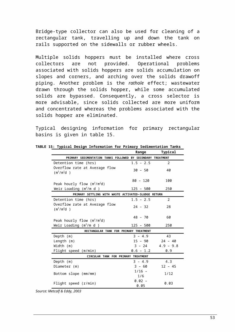
Sludge Retention Time
20 – 30 days
Detention Time 18 – 36 hoursMLSS Concentration
3,000 – 6,000 mg/L
Sludge Return Ratio 75 – 200% of process influentWater Depth 1.5 – 3 mOxygen Requirement
2.0 – 2.3 kg O2/kg BOD5 applied
Mixing Requirements
280 L/m min (length of aeration tank)
Sludge Production 0.2 – 0.6 kg/kg BOD5 removed
vi. High-Purity Oxygen Activated Sludge (HPOAS)The reactor for this type is staged, enclosed, providing an oxygen enriched gas phase for cocurrent flow with the mixed liquor. The addition of the influent wastewater and RAS takes place only at the first stage, with oxygen (typically purity of 98%). Three or four completely mixed cells (stages) comprise the unit. Each stage provides mixing for suspension of solids and oxygen dissolution. The devices that can be used are many, including slow speed mechanical surface aerators and submerged turbines. Higher volumetric oxygen transfer rates are allowed with the use of high-purity oxygen, by increasing the oxygen partial pressure in the gas of each stage. The higher volumetric oxygen transfer rates, allow the use of smaller bioreactor volumes with HRT values being around 2-4 hours. For municipal wastewater, the typical SRTs are 1-2 days, but longer time is required for industrial effluent. Offgas from the last bioreactor contains unused oxygen, impurities of the influent oxygen and carbon dioxide from biological behaviour. CO2
retention in the system can result to pH depression (pH 6-6.5) which subsequently results to adverse impacts on the growth of nitrifying bacteria.
vii. Selector Activated Sludge (SAS)Excessive growths of filamentous bacteria are controlled through SAS. A portion of the activated sludge system preceding the main bioreactor receives the influent and RAS, and has a high process loading factor; this is the selector. The sludge settleability in the selector is improved, by providing environmental conditions favouring the growth of flocculent at the expense of filamentous microorganisms. The selector may be constructed as a separate structure or simply be a portion of the bioreactor (Figure 12), baffled to provide the necessary process loading factor. The main bioreactor could be completely mixed or plug-flow; experience better with plug-flow.
53

FIGURE 12: Selector activated sludge (SAS) processSource: Grandy et al., 1999
viii. Sequencing Batch Reactor Activated Sludge (SBRAS) In a SBRAS, each reactor contains aeration and mixing equipment, and an effluent decanting system. The transfer of oxygen is achieved by diffused air, jet aerators, mechanical surface aerators or combined diffused air, and mechanical mixing. The influent flow, aeration, mixing and effluent decating functions are controlled by microprocessors. To take advantage of the increasing solids concentration resulting from the settle period, solids are usually wasted during the idle time. For the provision of at least one bioreactor to be always full, multiple reactors are generally provided. For improvement of the flexibility, most systems also make provision for a continuous operational mode. Even though some deterioration does take place, effluent of a good quality can be achieved and with only one operational bioreactor.
Comparison of Process Options
The advantages and disadvantages of the eight activated sludge process options described are summarised in the table that follows (Table 20).
TABLE 20: Comparison of Activated Sludge Process OptionsProcess Advantages DisadvantagesConventional
activated sludge (CAS)
▪ performance well characterised, predictable
▪ process and facility design well known
▪ operation parameters well characterised
▪ useful in wide range of applications
▪ moderate capital and operating costs
▪ moderate sludge settleability
Step-Feed Activated Sludge (SFAS)
▪ reduced bioreactor requirements compared to CAS
▪ reduced capital cost compared to CAS
▪ more complex operation▪ reduced nitrification efficiency
Contact stabilisation Activated Sludge (CSAS)
▪ reduced bioreactor requirements compared to CAS
▪ reduced capital cost compared to CAS
▪ more complex operation▪ reduced nitrification efficiency
Completely Mixed Activated Sludge (CMAS)
▪ simple design and operation▪ more resistant to toxic shock loads
than others▪ useful in a wide range of
applications
▪ moderate capital and operating costs
▪ susceptible to the growth of filamentous organisms
Extended Aeration Activated Sludge (EAAS)
▪ simple design and operation▪ reduced sludge production▪ organically stable waste sludge▪ high quality, well nitrified effluent
▪ large bioreactor volumes required▪ poor sludge settleability▪ higher oxygen requirement
High-Purity Oxygen ▪ small reactor volume ▪ mechanically complex
54
AerationBasin
ClarifierInfluent
Selector
RAS WAS
Effluent

Activated Sludge (HPOAS)
▪ more resistant to organic shock loads than others
▪ minimal air emissions
▪ incompatible with low process loading factors
Selector Activated Sludge (SAS)
▪ excellent sludge settleability▪ compatible with most activated
sludge process options
▪ relatively new option, limited experience
▪ increased mechanical complexity▪ increased sensitivity to toxic
organic compoundsSequencing Batch
Reactor Activated Sludge (SBRAS)
▪ simple design and operation▪ high quality effluent▪ process operational characteristics
adjustable by operational cycles adjustment
▪ discontinuous discharge▪ relatively large reactor volumes
Source: Grandy et al., 1999
Effluent Characteristics
The main parameters of interest determining the effluent quality of biological treatment of wastewater are organic compounds, suspended solids and nutrients, determined by the following constituents:
1. Soluble biodegradable organicsa. Organics that escaped biological treatmentb. Organics formed as intermediate products in the
biological degradation of the wastec. Cellular components (resulting from cell death or lysis)
2. Suspended organic mattera. Biomass produced during treatment that escaped
separation in the final settling tankb. Colloidal organic solids in the plant influent that
escaped treatment and separation3. Nitrogen and phosphorus
a. Contained in biomass in effluent suspended solidsb. Soluble nitrogen as ammonium, nitrate, nitride and
organic nitrogenc. Soluble orthophosphates
4. Non-biodegradable organicsa. Originally present in the influentb. By-products of biological degradation
In a well designed and operated activated sludge process used for the treatment of domestic wastewater with solids retention time of 4 days or more, the soluble carbonaceous BOD of a filtered sample is typically less than 3.0 mg/L. The predicted (theoretical) BOD content of the effluent is usually less 1mg/L, but in practice it is within 2-4 mg/L. The suspended solids can be 5-15 mg/L if a good secondary effluent and good settling sludge.
Secondary Clarification for Activated Sludge
As seen in the configuration figures shown previously (Figures 9, 11, 12), the bioreactor, where the process of activated sludge takes place, is always followed by a clarifier. The most common basis on which secondary clarification is designed is by considering the
55

surface overflow rate and the solids loading rate. Important in designing, is to take into consideration safety factors and the occurrence of peak events; occurrence of wastewater flow rate, return activated sludge flow rate and MLSS concentrations fluctuations.
Typical surface flow-rates used for the design are given in the Table 21, and they depend on the wastewater flow-rate instead of the mixed liquor flow-rate (overflow rate is equivalent to an upward flow velocity – the return sludge flow is drawn off from the bottom, not contributing to upward flow velocity). The effluent requirements and the need for consistency are the primary determinants for the selection of surface flow-rate.
TABLE 21: Typical design information for secondary clarifiers of the activated sludge processa
Type of treatmentDept
h(m)
Overflow rate (m3/m2d)
Solids Loading (kg/m2h)
Average Peak Average Peak
Settling following air-activate sludge (excluding extended aeration) 3.5-6 16-28 40-64 4-6 8Selectors, biological nutrient removal 3.5-6 16-28 40-64 5-8 9Settling following oxygen-activated sludge 3.5-6 16-28 40-64 5-7 9Settling following extended aeration 3.5-6 8-16 24-32 1-5 7Settling for phosphorus removal; effluent concentration, mg/L 3.5-6
Total P = 2 24-32Total P = 1b 16-24Total P = 0.2 – 0.5c 12-20
a adapted in part from Kang (1987); EWF (1998)b occasional chemical addition requiredc continuous chemical addition required for effluent polishingNOTE: Peak is a 2hour sustained peakSource: Metcalf & Eddy, 2003
7b. Trickling Filter
The term Trickling Filter, is used for the representation of an array of attached growth biochemical operations in which wastewater is applied to fixed media in an air-filled packed tower. The treatment is achieved by the microorganisms growing attached to the media. Trickling filters are aerobic and used for the oxidisation of biodegradable matter forming of biomass, which sloughs from the media and is separated from the treated wastewater in the downstream clarifier. Another process that can occur in a trickling filter is nitrification (ammonia-N to nitrate-N).
Process Description
The main components of a trickling filter are (Figure 13): the media bed, the containment structure, the wastewater dosing system, the under-drain system and the ventilation system.
56

FIGURE 13: Schematic Diagram of a Trickling FilterSource: Grandy et al., 1999
The surface upon which the microorganisms grow is the media bed, which can be made of or consists of rock, wood or synthetic plastic. There are many available types of arrangements and types to be used.
The applied wastewater and media are retained by the containment; for the latter, there are cases were the media are not self-supporting (e.g. rock, random plastic). In addition, it controls the effects of wind. Concrete, poured in place or precast panels is the most common material of which the containment is made of. Wood, fibreglass or coated steel are exampled of other materials that can be used, especially in cases where the media is self-supporting.
Wastewater is uniformly applied to the media bed by the application system. Uniformity is necessary to ensure that all media is wet. The performance of the process is affected by the application system, which can also be used as control of dosing frequency.
The treated effluent is collected by the underdrain system, for conveyance to discharge or further treatment. Underdrain is also used for allowing air to pass into the media bed. Typically for rock media, clay or concrete blocks are used, and sometimes these are reinforced with e.g. fibreglass.The necessary oxygen for the microorgnisms can be supplied via the vertical flow of air (natural draft or mechanically). The disadvantage of the natural draft ventilation is that there could be times that there is no density difference; air flow is caused by density differences inside the filter and outside. Nevertheless, air must uniformly be distributed across the media, ensuring that there is oxygen provided.
57
Effluent (further
treatment or discharge)Underdrain
MEDIA BED
Underdrain
Application (dosing)System
Influent
Recirculation (optional)
Air VentilationSystem
ContainmentStructure

Non-biodegradable matter (plastics, rags, etc) should be removed from the wastewater flow before it reaches the trickling filter, since it can easily clog the distributor and the media. This could result to unequal flow distribution and consequently poor performance. The removal of debris with coarse screens is not generally accepted where trickling filters are to be used; accepted debris removal can be achieved by fine screens (≤ 1 mm) or clarification, where the latter is the one more commonly used.
Even though trickling filters are considered aerobic, in most cases the biofilm (layer of biomass) formed on the media exceeds the depth of oxygen penetration. In other words, the biofilm consists of an outer aerobic layer and an inner anaerobic layer.
Factors Affecting PerformanceThe factors affecting the efficiency of the process of trickling filters are process loading, recirculation, media depth, temperature, ventilation, media type, distributor configuration, influent characteristics and effluent total suspended solids.
Process Options
Variations in the unit process of trickling filters arise from the objective of the treatment, type of media used, and the nature of other processes/operations in the process train. Factors to be considered, with the associated advantages and disadvantages are displayed in the table that follows (Table 22).
TABLE 22: Trickling Filter Process ComparisonProcess Advantages DisadvantagesTREATMENT OBJECTIVES
Roughing ▪ economical, particularly for high-strength wastewaters
▪ simple to design and operate
▪ process and facility design well known
▪ further treatment typically required prior to discharge
▪ generally requires secondary clarification
Carbon oxidation ▪ economical▪ simple to design and
operate▪ process and facility design
well known
▪ performance is consistent, but may not reliably meet stringent performance standards
▪ generally requires secondary clarification
Combined carbon oxidation and nitrification
▪ simple to design and operate
▪ relatively new process option, performance relationships not well characterised
▪ limited operator flexibilitySeparate stage
nitrification▪ simple to design and
operate▪ relatively new process
option, performance relationships not well characterised
MEDIA TYPERock ▪ large number of existing
applications▪ relatively expensive due to
structural constraints
58
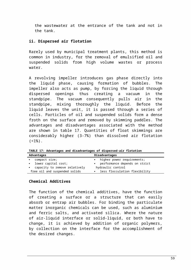
▪ quite effective at low to moderate organic loading rates
▪ not applicable for high loading applications
▪ odour potentialHigh-rate ▪ economical
▪ applicable to a wide range of process loadings and applications
▪ process and facility design well known
▪ media collapses have occurred due to improper application and/or manufacturing
COUPLED TRICKLING FILTER/ACTIVATED SLUDGETrickling filter/
solids contact▪ stable, reliable
performance▪ simple to design and
operate▪ low energy▪ process and facility design
well known
▪ moderate capital cost
Activated biofilter ▪ simple to design and operate
▪ low energy▪ process and facility design
well known
▪ process performance variable, except at low loading
Roughing filter/ activated sludge
▪ stable, reliable performance
▪ simple to design and operate
▪ low capital cost▪ process and facility design
well known
▪ moderate energy cost
Biofilter/ activated sludge
▪ stable, reliable performance
▪ simple to design and operate
▪ low capital cost▪ process and facility design
well known▪ improved sludge settling
characteristics in some applications
▪ moderate energy cost
Source: Grandy et al., 1999
Effluent Characteristics
Regardless of the process to be used, trickling filters have been considered to have major advantages in comparison to activated sludge process: smaller energy requirements and easier to operate; and the disadvantage of more odour potential and lower effluent quality. The technology has been used in several applications successfully, where it was properly designed. Table 23 shows typical applications, loadings and corresponding effluent quality of trickling filters.TABLE 23: Trickling Filter Applications, Loadings and Effluent Quality
Application Loading Effluent QualityUnit Range Unit Range
Secondary treatment kg BOD/m3da 0.3 - 1.0
BOD, mg/LTSS, mg/L
15 – 3015 – 30
Combined BOD removaland nitrification
kg BOD/m3dg TKN//m2db
0.1 - 0.3
0.2 - 1.0
BOD, mg/LNH4-N, mg/L
< 10< 3
Tertiary nitrification g NH4- 0.5 – NH4-N, mg/L 0.5 – 3
59

N//m2d 2.5
Partial BOD removal kg BOD/m3d 1.5 – 4.0
%BOD removal
40 - 70
a Volumetric loadingb Loading based on packing surface area
Source: Metcalf & Eddy, 2003
7c. Rotating Biological Contactor
Rotating biological contactor (RBC) is a term referring to a class of aerobic attached growth bioreactors that contain circular corrugated plastic media mounted on a horizontal shaft, partially submerged (typically 40%) in wastewater. With rotating speed of one/ two revolution per minute, the attached growth is alternate exposed to wastewater and atmosphere.
Biodegradable organic matter and nitrogen-containing compounds are metabolised by microorganisms growing on the media. The produced biomass sloughs off the media and transported by wastewater to a clarifier. At sufficiently low loading rate, nitrifying bacteria are allowed to grow on the media and convert ammonia-N to nitrate-N. Thus, wastewater which has already been partially treated can be applied to a RBC for nitrification.
Unit Description
The dimensions provided by almost all manufacturers are standard: media bundle of diameter 3.66 m and 7.62 m long, on a horizontal shaft 8.23 m long, with typical rotational velocity of 1.6 rpm and peripheral velocity of the disc 18.3 m/min.
The media is made up of high-density polyethylene containing UV inhibitors (e.g. carbon black). The individual sheets is corrugated similarly to plastic sheet trickling filter media, increasing the stiffness of the disc, increasing the available surface area, improve mass transfer and give a definition to the space between individual discs (i.e. media spacing/ density). Media of standard and high density have respectively, specific surface area of about 115 and 175 m2/ m3, with each standard shaft providing 9,300 and 13,900 m2 of media surface area. The media density to be used is determined by the wastewater characteristics and the objectives of the treatment.
Shaft (individual RBC units), are generally arranged in series for capacity and efficiency maximisation. The shafts are separated by baffles, into series of completely mixed bioreactor. Typically, each shaft typically has 45 m3 volume. The configuration of the system varies with the objectives: secondary treatment might use three stages in series with the first containing two shafts, whereas a
60

larger number of RBC shafts in series, is typically used in advance treatment (Figure 14).
a) Secondary Treatment Using Multiple RBC Units;
b) Advanced Treatment Using Multiple RBC Units;
c) Secondary Treatment Using a Single RBC Unit.
FIGURE 14: Examples of Rotating Biological Contactors TrainsSource: Grandy et al., 1999
Typically, the axis placement of each individual RBC shaft should be perpendicular to the direction of flow through the train. The rotation of the shafts should rotate in the direction causing the top of media to move opposite to the direction of flow, for minimisation of short circuiting.
The baffles in-between stages in a treatment train are not load bearing, so the individual shafts are not isolated. It is preferable the baffles to be free for movement, to allow adjustment where is needed (long term variations in process loadings).
Process Options
i. Treatment Objectives
61
1 2 3
Influent Effluent
Standard Density Media
Interstage Baffle
Stages:
1 2 3
Influent Effluent
Stages: 4 5 6
High Density Media
1 2 3Stages:
Influent Effluent
Interstage Baffle

RBCs are used for the removal of biodegradable organic matter and the conversion of ammonia and organic nitrogen to nitrate-N. The use is restricted for partial removal of organic matter, due to operational problems caused by high organic loading rates. They are however used efficiently for substantial removal of organic matter: a reduction to 30 mg/L can easily be achieved for BOD5 and TSS (for each) in clarified effluent. The degree of treatment depends primarily on finding the optimum organic and hydraulic loading rates.
Combination of carbon oxidation and nitrification can also be achieved in a RBC system. The oxidation of organic matter occurs during the fist stages of the process train. Reducing the soluble substrate concentration to about 20 mg/L as COD (25 mg/L as BOD5), the organic loading is sufficiently low for the organic substrate concentration to be reduced enough for the autotrophs oxidising organic carbon to be able to compete at latter stages of the process. Thus, organic loading distinguishes the level of treatment to be achieved, and whether or not nitrification will also be allowed.
RBCs can also be used for the nitrification of streams containing high ammonia-N and low organic matter concentrations; separate stage nitrification. Due to the low organic content, the process may not required clarification. An influent BOD5/ TKN ratio and/or BOD5
less than ~1.0 mg/L and 15 mg/L respectively, is an indication that separate stage nitrification will take place.Process Advantages and Disadvantages
The advantages and disadvantages of Rotating Biological Conductors are summarised in the table that follows (Table 24):
TABLE 24: Advantages and Disadvantages of Rotating Biological ConductorsAdvantages Disadvantages▪ mechanically simple▪ simple process, easy to operate▪ low energy requirements▪ modular configuration allows easy
construction and expansion
▪ performance susceptible to wastewater characteristics
▪ limited process flexibility▪ limited ability to scale-up▪ adequate pre-treatment required
Source: Grandy et al., 1999
Effluent Characteristics
Typical ranges of effluent characteristics according to organic, hydraulic, and ammonia loading etc. are shown in Table 25.
TABLE 25: Typical Design Information for Secondary Clarifiers of the Activated Sludge Process Parameter Unit Treatment levela
62

BOD removal
BOD removal &
nitrificationSeparate
nitrification
Hydraulic loading m3/m2d 0.08 – 0.16
0.03 – 0.08 0.04 – 0.10
Organic loading g sBOD/m2dg BOD/m2d
4 – 108 – 20
2.5 – 85 – 16
0.5 – 1.01 – 2
Maximum 1st stage organic loading
g sBOD/m2dg BOD/m2d
12 – 1524 – 30
12 – 1524 – 30
NH3 loading g N/m2d 0.75 – 1.5Hydraulic retention time h 0.7 – 1.5 1.5 – 4 1.2 – 3Effluent BOD mg/L 15 - 30 7 – 15 7 – 15Effluent NH4-N mg/L < 2 1 - 2
a Wastewater temperature above 13°CSource: Metcalf & Eddy, 2003
7d. Lagoons
A diverse array of suspended growth biochemical operations with common biochemical characteristics that do not include downstream clarifiers and associated with settled solids recycle is referred to as lagoon. Lagoons are typically used for the stabilisation of biodegradable organic matter. Removal of nitrogen (by nitrification/ denitrification and ammonia stripping) and phosphorus (by chemical precipitation) are also observed in some cases. The available options vary according to the type of metabolism occurring and the mechanism used for the provision of the terminal electron acceptor.
Process Description
Mechanical simplicity which characterises lagoons is often mistaken as low capital and operating costs. Behind though of this simplicity, there are many and complex physical, chemical and biological processes. Consequently, the understanding of the factors affecting the performance of the process is very little. A big problem associated with lagoons is the growth of algae, which after settling they pass into the effluent, increasing concentration of suspended solids biodegradable organic matter.
The structure of a lagoon is typically an earthen basin constructed with sloping sidewalls (Figure 15). Its configuration is often such, that the soil excavated from the interior is used for the construction of the sidewalls. To prevent penetration of the wastewater into the soil, a liner has become a common practice. Materials that are used commonly include natural clays, asphalt, synthetic membranes and concrete. The sidewalls above the water level are often covered with grass. Influent enters the lagoon at one end, and the treated effluent is collected on the opposite side. Solids retention time
63

approaches the hydraulic retention time, since no formal mechanisms are provided to retain biomass within the lagoon. Therefore, hydraulic retention times have the order of several days.
FIGURE 15: Schematic Diagram of a Lagoon (Vertical Dimension Exaggerated)Source: Grandy et al., 1999
The environmental conditions depend on the process loading and operating conditions, causing important variations in physical, chemical and biological conversions and consequently the effluent characteristics and process efficiency. In other words, lagoon refers to a configuration and not a set of controlled environmental conditions in a bioreactor.
Factors Affecting PerformanceThe factors affecting the efficiency of the lagoons are: solids retention time (SRT)/ hydraulic residence time (HRT), volumetric organic loading rate, area organic loading rate, mixing and temperature.
Process Options
i. Anaerobic Lagoon (ANL)An anaerobic lagoon is a low-rate anaerobic process, where a conversion to carbon dioxide and methane stabilises biodegradable organic matter. In comparison to other lagoons, ANL are relatively deep structures, with typical depth of 2 – 6 m. The surface area of the lagoon for a given volume is thus minimised, which consequently minimises oxygen transfer, release of odour and heat loss from the surface (important because ANL are not commonly covered). Coverage could allow the collection of methane gas and minimisation of odour release. Another option for minimisation of odour is the provision of oxygen in the top layers, allowing the oxidation of the odorous compound to less odorous before they leave the lagoon. Transfer of oxygen to the wastewater from the top air does take place, but the rate of biodegradable organic matter addition exceeds the rate of oxygen transfer. The loading
64
Grass or Concrete Covered Slope
Concrete Apron
Influent Effluent
Liner

rates also prevent the algae growth. Some mixing may take place in the lagoon from the gas evolution from the digested organic matter. Microbial growth takes place on surfaced provided on settleable solids and floating matter. HRTs could reach 20-50 days, but most common HRT used for design is 10. For a stable, effective anaerobic process to take place, an SRT of more than 20 days is required.
ii. Facultative and Facultative/Aerated LagoonThese are systems where both anaerobic and aerobic processes stabilise biodegradable organic matter: anaerobic in the lower parts of the lagoon and aerobic in the upper. The main oxygen provider in the upper layer is algae, with a small contribution from transfer through the air-liquid interface. However, the algal growth causes increase of the suspended solids and biodegradable matter in the effluent. Odour release is minimised by the oxidation of compounds released from the anaerobic zone at the aerobic zone. The effluent is collected from the aerobic zone.
Facultative lagoons are built as shallow basins for the promotion of the algal growth. Typical depths are 1 – 2 m, allowing maximum exposure of lagoon to the sun, minimising mixing, and balancing of the organic mater to oxygen ration by the oxygen production of algae. Being a system of which the efficiency if highly affected by the sunshine, diurnal variations of the incident light, are of great importance. The carbon dioxide produced varies with light and consequently the pH: 10 in daytime in aerobic (CO2 consumed by algae), 7 during night (CO2 produced by algae and bacteria).
The fluctuations in pH and the long HRTs are of great importance for the pathogen removal, including nematode eggs which settle. Lagoons can also be used for the removal of nitrogen (nitrification, denitrification and ammonia stripping) and phosphorus. However, due to the fluctuations of conditions, these processes are not consistent and effluent nutrient concentrations may vary.
Increasing the oxygen supply by mechanical could cause mixing. However, if the oxygen supply does not give sufficient energy for mixing, the two zones will be maintained and sufficient light will penetrate for algae growth.
iii. Aerobic LagoonThe design and operation of aerobic lagoons can be such to exclude algal growth by: biomass kept in suspension (increasing turbidity thus controlling light penetration) by mixing, which also makes SRT equal to HRT; control of HRT to be less than minimum required for algal growth (typically about 2 days) which consequently means that oxygen must be supplied by mechanically.
65

Aerobic lagoons can be used for conversion of biodegradable matter to biomass, thus allowing the removal of the first; stabilisation of organic matter by aerobic digestion (including synthesised biomass); and removal of synthesised mass by gravity settling. The objectives can be met through a variety of processes consisting of common steps. The first step of complete mixing (sufficient to keep everything in suspension) allows bacteria to oxidise a portion of biodegradable organic matter to carbon dioxide and water, and convert some to new biomass. As a result, the oxygen demand changes. Typically stabilisation is about 40%. SRTs of 2-3 days allow the complete conversion of biodegradable organic matter to biomass, and experience shows that the above is valid where HRT is equal to the SRT.
The construction of larger completely mixed aerobic lagoon or several in series, provide larger HRT allowing aerobic digestion of the synthesised biomass and other organic solids. This configuration has slightly more advantage in the overall stabilisation. Another option of further treatment is providing less mixing energy. Biosolids leaving the lagoon are stabilised by benthal process and removed by gravity sedimentation, and stored for later disposal. Benthal stabilisation is associated with anaerobic digestion, suggesting the production (end products) of methane, carbon dioxide, organic acids and nutrients (e.g. ammonia-N). End-products could be oxidised and passed into the upper portion of settled solids, if oxygen concentration of at least 2 mg/L is maintained in the clear water zone.
Effluent CharacteristicsBOD and TSS concentrations are the main effluent characteristics of the effluent from an aerated lagoon. For the minimum standards for secondary treatment to be achieved (according to US standards), settling facilities are needed. Slow sand or rock filters are commonly used in cases where greater removal of effluent solids is required.
Comparison of Process Options
The advantages and disadvantages of the aerobic lagoon processes available are summarised in Table 26. Factors considered include complexity of design and construction; energy requirements; capital, operational and maintenance costs; pathogen destruction; and many others.
TABLE 26: Lagoon Process ComparisonProcess Advantages DisadvantagesAnaerobic Lagoon ▪ simple construction
▪ low capital, operational ▪ poor process control▪ significant odour potential
66

and maintenance costs▪ simple operation▪ low solids production▪ effective and efficient▪ energy (methane) recovery
possible▪ flow and load equalisation▪ pathogen destruction
▪ effluent may require further treatment
▪ significant land area required
Facultative and Facultative/Aerated Lagoon
▪ simple construction▪ low capital, operational
and maintenance costs▪ simple operation▪ flow equalisation▪ low solids production▪ periodic solids
management▪ pathogen destruction
▪ large land area required▪ poor process control▪ unreliable process
performance▪ odour potential
Aerobic Lagoon ▪ simple construction▪ low capital costs▪ high effluent quality▪ simple operation▪ low sludge production▪ periodic solids
management▪ little odour production
▪ significant land area required
▪ moderate operational and maintenance costs
Source: Grandy et al., 1999
Typical Applications
In general, lagoons have been mainly used for pre-treatment of industrial wastewater. However, according to the nature of the lagoon the applications differ. These are summarised in Table 27.
TABLE 27: Typical Lagoon Applications
Anaerobic LagoonsFacultative and
Facultative/Aerated Lagoons
Aerobic Lagoon
Pre-treatment of industrial wastewater prior:▪ downstream mechanical treatment system;▪ downstream natural treatment system;▪ discharge to municipal wastewater treatment system
Pre-treatment of municipal and industrial wastewater prior:▪ downstream mechanical treatment system;▪ downstream natural treatment system
Pre-treatment of industrial wastewater prior to discharge to municipal wastewater treatment system
Pre-treatment of municipal wastewater prior:▪ downstream F/AL;▪ downstream natural treatment system;
Treatment prior to surface waste discharge (existing systems only)
Pre-treatment of municipal and industrial wastewater prior to downstream natural treatment system.
Treatment prior to surface water discharge
Source: Grandy et al., 1999
7e. Anaerobic Processes
67

Anaerobic process refers to a diverse array of biological wastewater treatment systems from which dissolved oxygen and nitrate-N are excluded. They are most commonly applied for the conversion of biodegradable organic matter (soluble and particulate) to methane and carbon dioxide. Through the process the methane can be recovered and inactivation of pathogens can be achieved. In some cases, anaerobic processes are used for the conversion of biodegradable particulate organic matter to volatile fatty acid; separated and fed to systems of biological nutrient removal, they enhance their performance.
A wide range of configurations for anaerobic processes are available, depending on the objective of the treatment. Anaerobic digesters, low-rate anaerobic processes and high-rate anaerobic processes, are used for the stabilisation of organic matter by conversion to methane and carbon dioxide. Solids fermentation processes are used for the production of volatile fatty acids.
i. Anaerobic Digestion
The aim of the process is stabilisation of particulate organic matter. Well mixed, with no liquid solids separation, the reactor can be treated as continues stirred tank reactor. HRT and SRT are identical, with typical SRTs being 15-20 days. Lower SRTs of up to 10 days have been used successfully, and longer SRTs are used where greater waste stabilisation is necessary.
The shape of the reactor is typically cylindrical of diameter 10 – 40 m, with cone shaped bottom, made up of concrete, and steel or concrete covers. The typical depth of sidewall is 5 – 10 m. The required mixing is achieved with internal mechanical mixers, external mechanical mixers recirculating the contents and various types of gas or pump recirculation systems.
As previously being mentioned, methane is generated by an anaerobic process; combusted, it can be used to heat the contents of the feed system and the digester. Typically, bioreactor temperatures are typically maintained mesophilic (~35°C). Gas production variations are compensated with gas storage, also allowing the operation of boilers and other equipment that can use the gas as fuel. Gas is most commonly stored in the digester under a cover floating on the contents.
The configuration of anaerobic bioreactors has developed for improved mixing characteristics and reduced accumulation of grit on the bottom and floating scum on the surface. A new development is an egg shaped digester developed in Germany. A large height-to-diameter ration, steep sloped lower and upper sections of the vessel, allow better mixing, reduction in grit and
68

scum accumulation and easier removal in cases of accumulation. Another digester allowing grit and heavy solids removal is the baffled bottom digester.
The performance of a digester is assessed by the percent VS destruction, since its aim is the stabilisation of biodegradable matter. 80 – 90% of influent biodegradable particulate organic matter is converted to methane at SRT of 15- 20 days; corresponding to ~60% destruction of VS in primary solids, and 30 – 50% in waste activated sludges.
There are cases where two digesters are operated in series, known as two-stage anaerobic digestion. In the first stage heating and mixing is provided, promoting active digestion, and the second, quiescent conditions promote the solid-liquid separation. Settled solids having been thickened from the second stage are directed for further processing or disposal, whereas supernatant is recycled to the liquid process train. The use though of the two-stage anaerobic digestion has declined due to various reasons concerning the efficiency of the process and technology progress. Subsequently, the most commonly used practice, is the thickening of feed solids prior to single-stage, high-rate anaerobic digestion.
ii. Low-Rate Anaerobic Processes
Low-rate anaerobic processes are slurry bioreactors utilising a combination of solids sedimentation and accumulation to increase the SRT relative to HRT. The type of basin typically used is earthen (Figure 16), whereas rectangular concrete vessels have also been used.
FIGURE 16: Low Rate Anaerobic Process Using an Earthen BasinSource: Grandy et al., 1999
Mixing occurs naturally, by the addition of the influent and the propagation of the gases to the top. The mixing conditions are not well provided, leading to settling of suspended solids and accumulation in the bioreactor. Recycling of settling solids has been incorporated to some systems, from the bottom of the reactor
69
Stored Gas
Gas
Influent Effluent
Cover
Reactor Contents

to the top. The generated gas is collected with membranes and similar materials, for further use.
The regulation of environmental conditions within low-rate processes is not well, which consequently does not allow accurate control of the SRT (regardless that accumulation of active biomass does take place). The impact this has on designing, is large since the only guidance is experience. Typical HRTs and organic loadings used are 5-15 days and 1-2 kg COD/m3day respectively.
iii. High-Rate Anaerobic Processes
For high-rate anaerobic processes, bioreactor configurations utilised provide significant retention of active biomass, generating large differences between SRT and HRT. Biomass is retained by (i) formation of settleable particles that are retained by sedimentation, (ii) use of appropriate configurations that allow retention of suspended solids, and (iii) growth of biofilms on surfaces within the reactor. The result is a wide range of processes to fall under the umbrella of high-rate anaerobic processes. Six types of bioreactors representing the utilisation of the processes for wastewater treatment will be considered next: (i) anaerobic contact, (ii) upflow anaerobic sludge blanket, (iii) anaerobic filters, (iv) hybrid upflow anaerobic sludge blanket and anaerobic filters, (v) down flow stationary fixed film, and (vi) fluidised bed/expanded bed.The performance of high-rate anaerobic processes, which can typically be achieved through the bioreactor configurations to be described next, are shown in Table 28.
TABLE 28: Typical High-Rate Anaerobic Processes Performance
Parameter Amount
BOD5 removal, percent 80 – 90 %COD removal, mass 1.5 x BOD5 removedBiogas production 0.5 m3/ kg COD removedMethane production 0.35 m3/ kg COD removedBiomass production 0.05 – 0.10 g VSS/ g COD
removedSource: Grandy et al., 1999
Anaerobic ContactA completely mixed suspended growth bioreactor, a degassifier, and a liquid-solids separation device, are the components of an anaerobic contact system. Anaerobic contact could also be named anaerobic activated sludge. Carbon dioxide and methane have to be removed, for the biosolids to settle in the liquid-solids separator. This is achieved by the degassifier. The configuration of the bioreactor is similar to that of an anaerobic digester. In the solid-liquid separation device, the effluent from the bioreactor is separated into a relatively clear process effluent and a concentrated slurry of biosolids recycled to the bioreactor.
70

Conventional clarifiers or plate settlers are often used for this purpose.
SRT is adjusted by the rate of solid wastage. The design and operation of the process focuses to maintain the desired value of SRT, which typically is 10-20 days. The corresponding HRT depends, as with activated sludge, on the concentration of active solids that can be attained in the bioreactor and the strength of the wastewater. Suspended solids in the bioreactor depend on the settleability of the developed solids, and are within the range of 4-6 g/L to 25-30 g/L as VSS, with the lower end being the typical values of operation. Common hydraulic loading of the clarifier is around 5-6 m/day, with solids recycle rate equal to the influent flow rate, and volumetric organic loading rats being between 0.5 – 10 kg COD/ m3d.
Upflow Anaerobic Sludge BlanketUpflow anaerobic sludge blanket uses suspended growth biomass, with the difference that the solid-liquid separator is integrated with the bioreactor, and not a separate unit. Large, readily settleable particles called granules can be formed in the bioreactor due to the environmental conditions. These allow accumulation of very high concentration of suspended solids, 20-30 g/L as VSS. Consequently, SRT and HRT have a typical difference of 2 days or less.
As influent wastewater enters uniformly the bottom of the bioreactor through a distribution system, (in combination with gas production) the dense slurry of granules formed on the bottom of the bioreactor is mixed with the influent. Additional to the blanket of granules in some wastewaters a much less dense flocculent sludge is formed and accumulates on top. Treated effluent leaves the layers (where treatment occurs) moving upwards to the gas-liquid-solids separator. Configurations for the separator are numerous, often consisting of a gas collection hood with a settler section above it.
The dimensions of the bioreactor depend on the process loadings, constraints on maximum upflow velocities, wastewater type and settling characteristics of the solids being developed during the process. As new mass grows and treatment occurs, the solids inventory increases. The sludges proportions can be controlled by allowing wasting locations to be used. Typical bioreactor HRTs are 0.2-2 days, with volumetric organic loading rates of 2 – 25 kg COD/ m3d, depending on the wastewater characteristics and the type of solids development (granular or flocculent).
Conditions and PerformanceThe table the follows (Table 29), gives examples for operating conditions used according to the wastewater treated and the COD
71
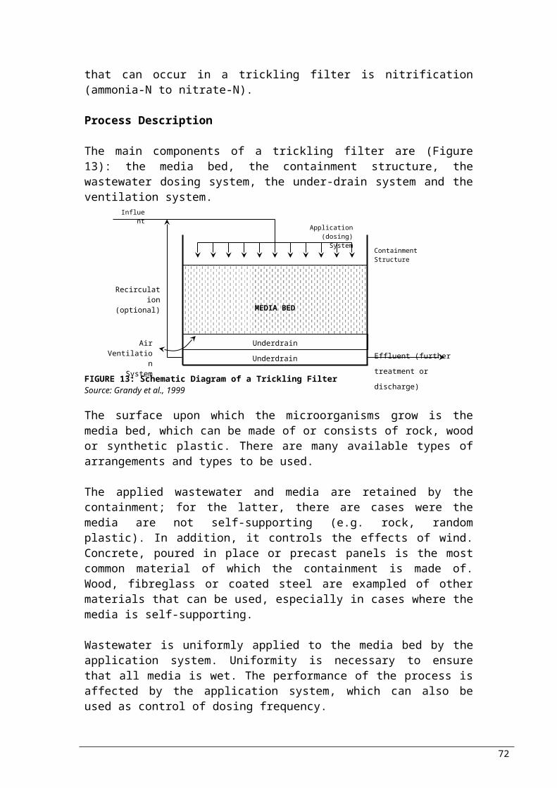
removal accomplished. Highlighted, is the example for domestic wastewater treatment, which is of primary concern for this study.
TABLE 29: Examples of Process Operating Conditions and Performance for Upflow Attached Growth Anaerobic Reactors
WastewaterPackingtype
Temp.(°C)
COD loading(kg/m3d)
RetentionTime (days)
Recycling Ratio (R/Q)
COD removed (%)
Guar gum Pall rings 37 7.7 1.2 5.0 61Chemical processing
Pall ringsPall rings
3715-25
12-150.1-1.2
0.9-1.30.5-0.75
5.0-
80-9050-70
Domestic Tubular 37 0.2-0.7 25-37 - 90-96Landfill leachate Cross-flow 35 1.5-2.5 2.0-3.0 0.25 89Food canning Cross-flow 30 4-6 1.8-2.5 - 90Source: Young, 1991
Anaerobic FiltersThese use upflow bioreactors filled with media, of which the packing is the same as that of aerobic plastic media trickling filters. The specific surface area is typically 100 m2/m3, with void volume 90-95%. Packing allows the growth of suspended biomass within the bioreactor, enhancing liquid-solid separation. Gas-solids separator is also facilitated within the packed section. Direct comparison of packing media, has shown that crossflow modular media is better due to superior gas-liquid-solids separation capabilities.
FIGURE 17: Anaerobic FilterSource: Grandy et al., 1999
Influent wastewater and recycled effluent are distributed across the cross-section of the lower end of the bioreactor, and flow upward through the media (Figure 17). Suspended and fixed biomass, are retained by the media, which corresponds to the occurring treatment. At the top of the media section the effluent exists and being collected for discharge, whereas under the cover of the bioreactor gas is collected and sent for use. Uniform hydraulic loading is maintained by recirculation of the effluent, thus maintaining uniform hydrodynamic conditions within the bioreactor. Even though the performance of the process is evaluated by the SRT, the amount of suspended solids in the
72
Effluent
MEDIA BED
Influent
Recycle
Gas

bioreactor is not generally possible to be known, accounting for the reason that HRT (typically 0.5 – 4 days) and volumetric organic loading rates (5 - 15 kg COD/ m3d) are used for designing. Excess biomass in the system, is washed out during its development, becoming part of the effluent. Additionally, settled solids could be removed from the bottom, mainly consisting of heavy solids and precipitates, which is not part of the control, since the active biomass is attached to the media.
Hybrid Upflow Anaerobic Sludge Blanket and Anaerobic FiltersCombining characteristics of both systems (upflow anaerobic sludge blanket and anaerobic filters), this system uses suspended biomass, with process loadings similar to upflow anaerobic sludge blanket, and so is the solids removal system. Influent wastewater and re-circulated effluent flow upward through the sludge blankets (flocculent and granular) after being uniformly distributed across the cross section of the bioreactor (Figure 18). Then it passes through a media bed as anaerobic filter. Gas is collected under the cover of the bioreactor.
FIGURE 18: Hybrid Upflow Anaerobic Sludge Blanket And Anaerobic Filters Process Source: Grandy et al., 1999
Down Flow Stationary Fixed FilmIn this system (Figure 19), suspended biomass tends to be conveyed through the media (which is the same as anaerobic filtration) instead of being retained. Nevertheless, the process depends on the attached biomass instead of the suspended. Wastewater is treated by the portion of biomass that is held in the media. Solids removal is not necessary, since the SS are of minor importance. As effluent exits the media zone, is collected for recirculation and discharge; the produced gas propagates upwards and collected under the cover. The specific surface area of the media used it typically higher than anaerobic filtration (140 m2/m3), which is vital for the attached growth. Typical HRT used, are within 0.5 - 4 days
73
Effluent
MEDIA BED
Influent
Recycle
Gas
Flocculent Sludge
Granular Sludge

and volumetric organic loading 5 - 15 kg COD/ m3d, values that are very similar to anaerobic filtration.
FIGURE 19: Downflow Stationary Fixed Film ProcessSource: Grandy et al., 1999
Fluidised Bed/Expanded BedThe main difference of fluidised and expanded bed systems to those previously being described is that the growth is predominantly attached growth, with little or no suspended growth. The result is much higher velocities in the upflow bioreactor (Figure 20), consequently leading to minimal retention of suspended biomass; the biomass grows attached to granular carrier particles fluidised by the upflow. Particles typically used for carriers are granular activated carbon or silica sand, with diameter 0.2-0.5 mm, and 2.65 specific gravity.
The flow rates should be sufficient to keep the carrier particles in suspension with the attacked biomass, i.e. expand the bed (typically by 15-30%). The velocities are higher in fluidised beds, causing larger expansion of 25-300%. The carrier particles have specific area of 9,000-11,000 m2/m3 in expanded bed bioreactors, and 4,000-10,000 m2/m3 in fluidised bed bioreactors, allowing the development of high biomass concentrations of the magnitude 25-35 g/L as VSS. This also allows operation at relatively low HRTs (0.2-2 days) and high VOL (>20 kg COD/ m3d), while adequate SRT is maintained for efficient treatment.
74
Effluent
MEDIA BED
Influent
Recycle
Gas

FIGURE 20: Fluidised Bed and Expanded Bed processSource: Grandy et al., 1999
iv. Solids Fermentation Processes
These processes are used for the solubilisation of particulate organic matter in primary solids and fermentation of soluble products to Volatile Fatty Acids (in particular acetic and propionic). The objectives are: Maximisation of VFA production: achieved by SRT control (2-3
days at 35˚C), by addition of hydraulitic and fermentative bacteria. In cases of low temperatures, SRT must increase. Some methane will be produced.
Separation of VFA from residual primary solids: passing of effluent through the step of liquid solids separation
Comparison of Anaerobic Processes
The main advantages and disadvantages of the anaerobic treatment systems used for the stabilisation of organic matter are summarised in Table 29.
TABLE 29: Anaerobic Treatment Process Comparison for Organic StabilisationProcess Advantages DisadvantagesAnaerobic digestion ▪ suitable for a wide range of
wastewaters▪ efficiently handles high concentrations of SS
▪ easy to mix, thereby creating uniform reaction environment
▪ large biorector volume to dilute inhibitors
▪ performance not dependent on sludge settleability
▪ capable of accepting waste aerobic biomass
▪ large bioreactor volumes required▪ effluent quality can be poor if non-degradable matter is present or if a large concentration of anaerobic organisms are generated
▪ process stability and performance poor at short SRTs
▪ required separate mechanical mixing
Low-rate anaerobic processes
▪ simple and relatively economical construction
▪ suitable for a wide range of wastewater
▪ efficiently handles high concentrations of SS
▪ large biorector volume to dilute
▪ relatively large bioreactor volumes required
▪ large land area required▪ poorly controlled conditions within bioreactor reduce efficiency
▪ limited process control capability
75
Effluent
FLUIDISED/ EXPANDED MEDIA BED
Influent
Recycle
Gas
Media and Biomass Separation
Cleaned/ Recycled Media

inhibitors▪ performance not dependent on sludge settleability
▪ capable of accepting waste aerobic biomass
▪ good performance possibleAnaerobic contact ▪ suitable for concentrated
wastewater▪ easy to mix, thereby creating uniform reaction environment
▪ relatively high quality effluent achievable
▪ reduced bioreactor volume compared to aerobic digestion
▪ capable of accepting waste aerobic biomass
▪ biomass settleability critical to successful performance
▪ most suitable for wastes with low to moderate levels of suspended solids
▪ system is relatively complex mechanically
▪ shorter bioreactor HRTs mean less equalisation and dilution of inhibitors
Upflow anaerobic sludge blanket
▪ high biomass concentrations and long SRTs achievable
▪ small bioreactor volumes due to high volumetric organic loading rates
▪ high quality effluent achievable▪ mechanically simple▪ compact system, relatively small area
▪ well mixed conditions produced
▪ performance dependent on development of dense, settleable solids
▪ much lower process loading required if wastewater contains suspended solids
▪ special bioreactor configuration required which is based on experience
▪ little process control possible▪ shorter bioreactor HRTs mean less equalisation and dilution inhibitors
Anaerobic filter ▪ high biomass concentrations and long SRTs achievable
▪ small bioreactor volumes due to high volumetric organic loading rates
▪ high quality effluent achievable▪ mechanically simple▪ compact system, relatively small land area
▪ performance not dependent on development of dense settleable solids
▪ well mixed conditions produced in bioreactor
▪ suspended solids accumulation may negatively affect performance
▪ not suitable for high SS wastewater
▪ little process control possible▪ high cost for media and support▪ shorter bioreactor HRTs mean less equalisation and dilution inhibitors
Hybrid Upflow anaerobic sludge blanket / Anaerobic filter
▪ high biomass concentrations and long SRTs achievable
▪ small bioreactor volumes due to high volumetric organic loading rates
▪ high quality effluent achievable▪ mechanically simple▪ compact system, relatively small land area
▪ performance partially dependent on development of dense settleable solids
▪ well mixed conditions produced in bioreactor
▪ reduced media cost
▪ lower process loadings required if wastewater contains SS
▪ little process control possible▪ shorter bioreactor HRTs means less equalisation and dilution inhibitors
Downflow stationary fixed film
▪ high biomass concentrations and long SRTs achievable
▪ small bioreactor volumes due to high volumetric organic loading rates
▪ high quality effluent achievable▪ mechanically simple▪ compact system, relatively small land area
▪ performance not significantly affected by high suspended solids wastewater
▪ performance not dependent on development of dense settleable solids
▪ well mixed conditions produced in bioreactor
▪ biodegradable SS not generally degraded
▪ high cost of media and support▪ organic removal rate generally lower than other high-rate processes
▪ little process control possible▪ shorter bioreactor HRTs means less equalisation and dilution inhibitors
76

Fluidised bed/ expanded bed
▪ high biomass concentrations and long SRTs achievable
▪ small bioreactor volumes due to high volumetric organic loading rates
▪ excellent mass transfer characteristics
▪ high quality effluent achievable, often better than other high rate processes
▪ performance not dependent on development of settleable solids
▪ very well mixed conditions generally produced in bioreactor
▪ increased process control capability relative to other high-rate processes
▪ lengthy start-up period required▪ high power requirements for bed fluidisation and expansion
▪ not suitable for high SS wastewater
▪ mechanically more complex than other high-rate processes
▪ cost of carrier media is high▪ shorter bioreactor HRTs mean less equalisation and dilution of inhibitors
Source: Grandy et al., 1999
Typical Applications
stabilisation of wastewaters of organic matter content >1,000 mg/l COD
not economic compared to aerobic for more dilute wastewaters advantages in comparison to aerobic: (i) less solids production;
(ii) lower nutrient requirements; (iii) lower energy requirements; (iv) production of methane, a potentially useful product; (v) capable of degradation of organic compounds not metabolised in aerobic (e.g. chlorinated organics)
disadvantages in comparison to aerobic: (i) not as good effluent quality, may need aerobic polishing; (ii) more sensitive to shock loads and presence of toxic materials
in cases of wastewaters of organic matter content 1,000 - 4,000 mg/l COD:
o temperature: anaerobic best at mesophilic (30-40˚C) or thermophilic (50-60˚C); deviations cause reduction in microbial activity increasing SRT
impact of temperature greater on SRT for anaerobic than for aerobic
high-rate anaerobic treatment developed for SOM: high SS concentrations reduces efficiency; stabilisation determined by organic matter stabilisation
wastes with high lipids concentration: longer SRT for acidogenesis increasing required SRT for an anaerobic process
anaerobic digestion typically used for treatment of high strength wastewaters; in particular high suspended solids concentration:
o high-rate anaerobic treatment: <20,000 mg/l CODo low-rate anaerobic treatment: 20,000-30,000 mg/l COD
factors affecting performance: (i) solids retention time; (ii) volumetric organic loading rate; (iii) total hydraulic loading; (iv) temperature; (v) pH; (vi) inhibitory and toxic materials; (vii) nutrients; (viii) mixing; (ix) waste type
77

In many wastewater treatment plants, tertiary treatment, being described in the chapter that follows, is the last level of treatment. The effluent IS of high quality, but for some uses of wastewater is not sufficient.
78

8. Tertiary Treatment
In case that the treatment effluent is to be discharged in natural water bodies, high nutrient concentrations are directly related to eutrophication. Specific effluent uses though may not need the nutrients to be removed, because for example, nitrogen and phosphorus are good for the crops at which the effluent will be used. Removal of nutrients can be achieved biologically and chemically. The unit process of disinfection is described in this chapter.
8a. Removal of Nutrients
Removal of nutrients can be achieved biologically or by the addition of chemicals in the case of phosphorus (chemical precipitation/ coagulation and flocculation).
i. Biological Nitrogen Removal
Nitrogen can be removed from wastewater by nitrification and denitrification, being described next.
NitrificationNitrification is the term used for the description of a two-step biological process in which ammonia is oxidised to nitrite, and nitrite oxidised to nitrate. Nitrification is required because of: the impact ammonia has on DO concentrations and fish toxicity
in the receiving waters; control of eutrofication by nitrogen removal; control of nitrogen for water-reuse applications
Nitrification can be achieved via both suspended growth and attached biological process (see previous section). For the first, nitrification takes place along with BOD removal during the same process, consisting of an aeration tank, clarifier and sludge recycling system. Two sludge suspended growth system is considered where there is significant potential for toxic and inhibitory substances in the wastewater: consisting of two aeration tanks and two clarifiers in series, with the first at short SRT for BOD removal allowing nitrification at the second. Systems designed for nitrification have much longer hydraulic and solids retention times than systems for BOD removal, since nitrifying bacteria growth much slower than heterotrophic bacteria (responsible for BOD removal).
Nitrification by attached growth is achieved after the removal of BOD or in a separate attached growth system design specifically.
79

Environmental factors by which nitrification is affected include pH (optimal at 7.5 – 8.5), toxicity (inhibiting factor), metals (inhibiting factor) and un-ionised ammonia (inhibiting factor).
DenitrificationDenitrification is the term used for the biological reduction of nitrate to nitric acid, nitrous oxide and nitrogen gas, and is used in wastewater treatment for removal of nitrogen. Other technologies to which it can be compared are ammonia stripping, breakpoint chlorination and ion exchange; from which denitrification is the most cost-effective and consequently the most commonly used. It typically takes place in activated sludge process (Figure 21 & 22).
FIGURE 21: Nitrogen Transformations in biological treatment processesSource: Sedlak, 1991
(a) substrate driven (preanoxic denitrification)
(b) endogenous driven (postanoxic denitrification)
FIGURE 22: Types of denitrification processes and the reactors used for their implementationSource: Metcalf & Eddy, 2003
80
Bacterial decomposition and hydrolysis
Assimilation
Organic nitrogen(proteins; urea)
Ammonia nitrogen
Nitrite (NO2-)
Nitrate (NO3-) Nitrogen gas (N2)
Organic nitrogen(bacterial cells)
Organic nitrogen(net growth)
Denitrification
Lysis and autooxidation
Organic Carbon
O2
O2
Nitr
ifica
tion
Anoxic Aerobic/ nitrification
Influent Effluent
Return activated sludge
Nitrate feed
Sludge
EffluentAnoxicAerobic/ nitrification
Influent
Return activated sludge
Sludge

ii. Phosphorus Removal
The removal of phosphorus can be achieved biologically or via chemical precipitation. It is an essential measure taken for eutrophication control of receiving waters. The second mean of removal, chemical precipitation by the addition of alum or iron salts is the most commonly used technology. The advantages though of biological over chemical phosphorus removal are associated with cost, and smaller quantities of sludge.
Biologically
The typical configuration of a biological phosphorus removal system is illustrated in Figure 23. The retention time of the anaerobic tank is 0.5 – 1 hrou. Mixing is provided in the anaerobic tank allowing contact with the activated sludge being recycled.
FIGURE 23: Typical reactor configuration for biological phosphorus removalSource: Metcalf & Eddy, 2003
DO does not affect the performance of the system, for aerobic zone concentrations greater than 1 mg/L. The efficiency though is affected in case that the pH drops below 6.5; i.e. the phosphorus removal reduced. Another condition that must be satisfied for this system is the presence of sufficient cations related to polyphosphate storage. The amounts contained in most municipal wastewaters are sufficient, but care must be taken in cases of industrial laboratory wastewater.
Chemical Precipitation
The processes, by which chemical precipitation takes place moving phosphorus, are coagulation and flocculation.
Coagulation
Coagulation is defined as destabilisation of colloidal particles caused by the addition and of chemicals known as coagulants, to allow the formation of larger particles (flocs) through flocculation (section). Without going into further detail for the theory of coagulation, the ability of a substance to cause destabilisation of
81
Anaerobic rector: PHB stored internally, poly P
hydrolysis, and P release
Aeration tank: biomass synthesis and decay, PHB utilization, and enhanced
poly P uptake
EffluentInfluent
Return activated sludge
Sludge
Clarifier

particles is associated to its charge and size. Possible options for coagulants in wastewater treatment are (1) potential-determining ions, (2) electrolytes, (3) polyelectrolytes and (4) hydrolysed metal ions.
The addition of potential-determining ions can be illustrated by the addition of strong acids or bases, causing reduction in the charge of metal oxides or hydroxides to near zero. Addition of electrolytes in high concentration causes reduction of the force caused by repulsive forces between particles. Polyelectrolytes are divided into two types; natural and synthetic. Depending on their nature they are distinguished into further categories: biological origin and starch products for natural; and simple monomers whose charge may change (to positive, negative or neutral) when placed in water. Hydrolysed metal ions could cause coagulation due to adsorption and charge neutralisation, adsorption and inter-particle bridging, or enmeshment in sweep floc.
The selection of coagulant to be used for a wastewater treatment plant requires laboratory or pilot studies, since a given wastewater may show optimum coagulation results with a particular coagulant. Nevertheless, there are certain coagulants being used widely in wastewater treatment: alum (Al III) salts, ferric (Fe III) salts, ferrous (Fe II) salts, lime (calcium hydroxide) and sodium salts (Table 30).
The dosage required for coagulation to take place, depends on the nature of the colloidal particles, the pH and temperature of the wastewater, and particular constituents of the wastewater such as organic matter. The type of mixing necessary to promote coagulation is crucial, since the process is time-depended. Sometimes coagulant aids such as recycled sludge or polyelectrolytes are required for the production of rapid-settling floc. Following, a brief description is given on the most important characteristics of coagulants given in Table 30.
TABLE 30: Inorganic Chemicals Used Most Commonly For Coagulation (And Chemical Precipitation) In Wastewater Treatment
Chemical Formula AvailabilityForm Percent
Alum Al2(SO4)318H2
OaLiquidLump
8.5 (Al2O3)17 (Al2O3)
Al2(SO4)314H2
OaLiquidLump
8.5 (Al2O3)17 (Al2O3)
Aluminium chloride AlCl3 LiquidCalcium hydroxide (lime) Ca(OH)2
LumpPowderSlurry
63-73 as CaO85-9915-20
Ferric chloride FeCl3LiquidLump
20 (Fe)20 (Fe)
Ferric sulphate Fe2(SO4)3 Granular 18.5 (Fe)Ferrous sulphate FeSO47H2O Granular 20 (Fe)Sodium aluminate Na2Al2O4 Flake 46 (Al2O3)
82

a Number of bound water molecules will typically vary from 14-18.Source: Metcalf & Eddy, 2003
AlumWhen alkanity is present in the wastewater in the form of calcium and magnesium bicarbonate, the precipitate of aluminium hydroxide takes place, on the addition of aluminium sulphate or aluminium chloride. The floc caused by the aluminium hydroxide precipitate is of a gelatinous form, settling slowly through the wastewater, collecting suspended material in its course. The amount of alkalinity required for the reaction of 10 mg/L of alum is 4.5 mg/L (using the CaCO3 molecular weight of 100). In rare cases where the alkalinity is lower, is increased by the addition of lime.
LimeThe precipitate formed on addition of lime is CaCO3, by the combination with all free carbonic acid and the carbonic acid of the bicarbonates. Typically, the amount of lime required is much more than when added with sulphate of iron. In cases where the wastewater to be treated originates from industry, suggesting the presence of mineral acids or acid salts, neutralisation must take place beforehand.
Ferrous sulphate and limeFerrous sulphate is not usually used alone, but added simultaneously with lime for the formation of precipitate (added in excess in cases where the alkalinity is low). The precipitate of ferric hydroxide forms after ferrous hydroxide is oxidised by dissolved oxygen in wastewater. The form of the floc is similar to that of alum. The amount of alkalinity, lime and oxygen required for 10 mg/L of ferrous sulphate is 3.6 mg/L, 4.0 mg/L and 0.29 mg/L respectively. In most wastewaters, the amount of dissolved oxygen present is not enough for the required reactions for the formation of the precipitate to take place. Consequently, ferrous sulphate is not commonly used in the treatment of wastewater.
Ferric chlorideThe problems associated with the use of ferrous sulphate, lead to the use of ferric chloride to be used in application of precipitation. The precipitate formed is ferric oxide. This salt could also be used in combination with lime, as explained earlier (with ferrous sulphate).
Ferric sulphate and limeAnother iron salt being used is ferric sulphate. Once again the precipitate formed is ferric hydroxide.
Coagulant Aids
83

Coagulant aids are sometimes required for the optimisation of coagulation, caused by the production of a quick forming, dense, rapid-settling floc. Addition of alkalinity is needed where the alkalinity of the wastewater treated is insufficient for the production of a good floc. Lime is the most commonly used in the form of slaked lime (milk of lime) or hydrated lime; soda ash (sodium carbonate) is available in powder form enabling dry feeding, but used less due to the cost.
Polyelectrolytes could also be used due to the ionic characteristics. They are frequently in powder form and may require special conditions for the formation of solution. Turbidity could also be increased by the recycling of chemically precipitated sludge before the mixing basins or addition of clay. pH adjustment is commonly required to bring the wastewater to a pH that solubility of the metal hydroxide is minimum: increase by lime addition, reduction by mineral acid (e.g. sulphuric).
Flocculation
Flocculation takes place after rapid mixing, where the coagulant is added to the wastewater. Flocculation is further separated into microflocculation and macroflocculation. The type to take place depends on the size of the particles involved; i.e. the size of particles that have to be removed.
The factors affecting the chemical to be used for phosphorus removal are (Kugelman, 1976):
1. influent phosphorus level;2. wastewater suspended solids;3. alkalinity;4. chemical cost (including transportation);5. reliability of chemical supply;6. sludge handling facilities;7. ultimate disposal methods;8. compatibility with other treatment processes
8b. Disinfection
Disinfection is the destruction of pathogenic microorganisms, only. The characteristics required for the perfect disinfectant are shown in the table that above. In reality, such a substance may not exist, but these should be the factors to be considered when choosing a disinfectant.
TABLE 31: Characteristics of the ideal disinfectantCharacteristic Properties/responseAvailability Should be available in large quantities and
reasonably priced
84

Deodorising ability Should deodorise while disinfectingHomogeneity Solution must be uniform in compositionInteraction with extraneous material
Should not be absorbed by organic matter other than bacterial cells
Non-corrosive and non-staining
Should not disfigure metals or stain clothing
Non-toxic to higher forms of life
Should be toxic to micro-organisms and non-toxic to humans and other animals
Penetration Should have the capacity to penetrate through surfaces
Safety Should be safe to transport, store, handle and useSolubility Must be soluble in water or cell tissueStability Should have low loss of germicidal action with time
on standingToxicity to microorganisms Should be effective at high dilutionsToxicity at ambient temperatures
Should be effective in ambient temperature range
Source: Metcalf & Eddy, 2003
Types of disinfectants
Disinfection can be achieved by the use of (i) chemical agents, (ii) physical agents, (iii) mechanical means, and (iv) radiation.
Chemical AgentsCompounds that have been considered and have been used as disinfectants include: (1) chlorine and its compounds; (2) bromine; (3) iodine; (4) ozone; (5) phenol and phenolic compounds; (6) alcohols; (7) heavy metals and related compounds; (8) dyes; (9) soaps and synthetics; (10) quaternary ammonium compounds; (11) hydrogen peroxide; (12) paracetic acid; (13) certain alkalies and acids. The most commonly used out of these, are oxidising agents, with chlorine being the most common.Physical AgentsHeat, light and sound can also be used for disinfection. Heat is commonly used in industries for disinfection, whereas is not economically viable to be used in wastewater treatment. Sunlight, containing UV radiation, causes decay of micro-organisms, a fact that can be observed in oxidation ponds. Consequently, special lamps have been developed and being used efficiently for the emission of ultraviolet light. An important factor to consider for designing is the contact geometry: suspended matter, organic molecules and water, also absorb the radiation.
Mechanical MeansMechanical means such as screens can also be used for the removal/ destruction of microorganisms, as secondary function of the process/ operation. Associated removal with specific treatment units are shown in the table that follows.
TABLE 32: Removal or destruction of bacteria by different treatment processes or operations
Process Removal (%)
Coarse screens 0 – 5
85

Fine screens 10 – 20Grit chambers 10 – 25Plain sedimentation 25 – 75Chemical precipitation 40 – 80Trickling filters 90 – 95Activated sludge 90 – 98Chlorination of treated wastewater
98 – 99.999
Source: Metcalf & Eddy, 2003
RadiationTypes of radiation that could be used for wastewater treatment are electromagnetic, acoustic, and particle. There are still no commercial devices that can be used for the application of high energy electron beam, whereas gamma rays (emitted from radio-isotopes such as cobalt-60) have been used for the sterilisation of water and wastewater.
Comparison of available methods
TABLE 33: Comparison of commonly used disinfectants to the ideal caseCharacteristic Chlorine
Sodium hypochlorit
e
Calcium hypochlorit
eChlorine dioxide Ozone UV
radiation
Availability Low cost Moderately low cost
Moderately low cost
Moderately low cost
Moderately high cost
Moderately high cost
Deodorising ability
High Moderate Moderate High High n/a
Homogeneity Homogeneous
Homogeneous
Homogeneous
Homogeneous
Homogeneous
n/a
Interaction with extraneous material
Oxidises organic matter
Active oxidiser
Active oxidiser
High Oxidises organic matter
Absorbance of UV
radiation
Non-corrosive and non-staining
Highly corrosive
Corrosive Corrosive Highly corrosive
Highly corrosive
n/a
Non-toxic to higher forms of life
Highly toxic to higher life
forms
Toxic Toxic Toxic Toxic Toxic
Penetration High High High High High ModerateSafety concern
High Moderate Moderate High Moderate Low
Solubility Moderate High High High High n/aStability Stable Slightly
unstableRelatively
stableUnstable, must be
generated as used
Unstable, must be
generated as used
n/a
Toxicity to microorganisms
High High High High High High
Toxicity at ambient temperatures
High High High High High High
Source: Metcalf & Eddy, 2003
Table 33 summarises the main characteristics of the most common disinfectants used for wastewater treatment.
Factors Affecting Performance of Disinfectants
The factors to be considered during the application of the disinfectant are (i) contact time, (ii) concentration, (iii) intensity
86

and nature of physical means, (iv) temperature, (v) types of organisms, (vi) nature of suspended liquid. The action of the disinfectants is determined by the analysis of data derived using discrete organisms in solution. Shielding of the organisms could be provided by the suspended matter, which is the reason why the nature of suspended liquid is also considered. For the design of the process, formulae are used for the theoretical destruction of pathogens according to variations of specific parameters.
i. Chlorine & Chlorine Compounds
Chlorine is the most commonly chemical disinfectant, since it satisfies most of the requirements for a disinfectant. The principal chlorine compounds used for wastewater treatment are chlorine (Cl2), sodium hypochlorite (NaOCl), calcium hypochlorite (Ca(OCl)2) and chlorine dioxide (ClO2).
FIGURE 24: Theoretical Breakpoint Chlorination Scheme at: 1.0mg/L ammonia-nitrogen; pH 7; temperature 25˚C; contact time 2 hours. Source: Wolfe et Al., 1984
The effectiveness of a chlorine compound is directly related to actual and available chlorine; with available chlorine being used to compare the oxidising power of the compounds.
The addition of chlorine or a chlorine compound is associated with a breakpoint (Figure 24), acid generation (Figure 25), build-up of total dissolved solids and chlorine residual.
87

FIGURE 25: Affect of pH on the form of chlorine; Forms of Chlorine Present in Water across the pH range of 0 - 9 Source: Rittmann, 1997
Factors affecting the efficiency of chlorine are initial mixing, chemical characteristics of wastewater (Table 34), impact of wastewater particles, particles with coliform organisms and the characteristics of the microorganisms present.
TABLE 34: Impact of wastewater constituents on the use of chlorine for wastewater disinfection Constituent EffectBOD, COD, Toc, etc.
Organic compounds comprising the BOD and COD can exert a chlorine demand. The degree of interference depends on their functional groups and their chemical structure
Humic materials Reduce effectiveness of chlorine by forming chlorinated organic compounds that are measured as chlorine residual but are not effective for disinfection
Oil, grease Can exert a chlorine demandTSS Shield embedded bacteriaAlkalinity No or minor effectHardness No or minor effectAmmonia Combines with chlorine to form chloraminesNitrite Oxidised by chlorine, formation of N-nitrosodimethylamine
(NDMA)Nitrate Chlorine dose is reduced because chloramines are not formed.
Complete nitrification may lead to the formation of NDMA due to the presence of free chlorine. Partial nitrification may lead to difficulties in establishing the proper chlorine dose
Iron Oxidised by chlorineManganese Oxidised by chlorinepH Affects distribution between hypochlorous acid and hypochlorite
ionIndustrial discharges
Depending on the constituents, may lead to diurnal and seasonal variations in the chlorine demand
Source: Metcalf & Eddy, 2003
Chlorine, Cl2
Chlorine is available in liquid and gas form. Non contained liquid vaporises rapidly at standard temperatures and pressures. Consequently chlorine is supplied as liquefied gas under pressure in containers of varying size. The size depends on rate of chlorine usage, cost, facilities and dependability of supply. The disadvantages and issues associated with chlorine use are summarised in Table 35 below.
88

TABLE 35: Concerns associated with chlorine use.Issue1. Highly toxic, transported by rail or truck;2. Highly toxic, posing health risks to operators and public;3. Stricter containment and neutralisation requirements needed for safety;4. Odorous compounds formed on reaction with organic constituents of wastewater;5. Carcinogenic and/ or mutagenic by products formed on reaction with organic
constituents of wastewater;6. Residual chlorine toxic to aquatic life;7. Long-tem effects of chloro-organic compounds are not known, leading to concerns
over discharge to environment
Sodium hypochlorite, NaOClTransport, storage and feeding concerns associated with chlorine, are eliminated by the use of calcium or sodium hypochlorite. The disadvantages are: must be stored in a corrosion resistant tank at cool temperatures, chemical cost (150-200% of liquid chlorine), special design considerations for handling (corrosiveness and chlorine fumes). Sodium hypochlorite can be generated by various proprietary systems from sodium chloride or seawater, an option which is quite expensive due to high power requirements and complex.
Calcium hypochlorite, Ca(OCl)2
Found commercially in dry (powder, granules, tablets or pellets) or wet form, it contains at least 70% available chlorine. Regardless the form, calcium hypochlorite should be stored in a dry, cool location away from other chemicals due its high oxidising potential. The compound loses strength on storage, may be difficult to handle and more expensive than liquid chlorine, therefore being used more at small plants.
Chlorine dioxide, ClO2
The disinfecting power of chlorine dioxide is equal or greater than chlorine. It has been proven to be an effective virocide, inactivating viruses more effective than chlorine. The reason could be that chlorine dioxide is absorbed easier than chlorine by a protein coating viruses. Until recently, ClO2 did not receive much attention due to reasons associated with cost.
ii. Ozone
Ozone can be used in wastewater treatment for odour control. It can be produced by electrolysis, photochemical reaction, or radiochemical reaction by electrical discharge, with the latter being used for the ozone required by wastewater treatment. Ozone can be detected before it causes any health hazards, due to its distinct odour; and it can be explosive at concentrations of about 240 g/m3.
The main components of an ozone disinfection system are: power supply (Table 36), facilities for the preparation of the feed gas,
89
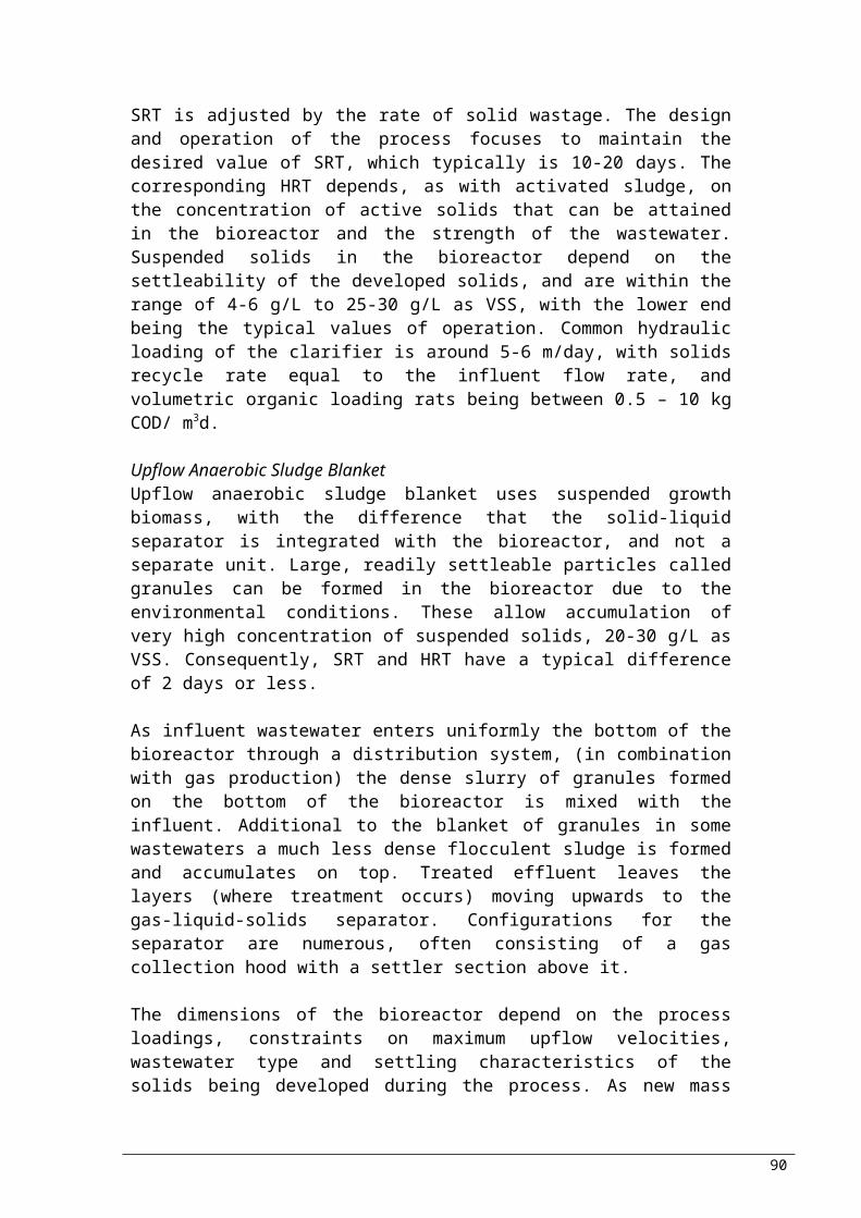
facilities for ozone generation, facilities for contacting ozone with liquid, and facilities for the destruction of the off-gas.
TABLE 36: Typical energy requirements for the application of ozoneComponent kWh/kg
ozoneAir preparation (compressor and dryers)
4.4 – 6.6
Ozone generation:Air feed 13.2 – 19.8Pure oxygen 6.6 – 13.2
Ozone contacting 2.2 – 6.6All other uses 1.2 – 2.2
Source: Metcalf & Eddy, 2003
The formation of unwanted by-products is one of the problems associated with ozone. In addition, it has been reported that ozone residuals can be toxic to aquatic life (Ward et al., 1976). But, due to rapid dissipation, ozone residuals will not normally be found by the time the effluent is discharged.
Benefits associated with the use of ozone as disinfectant:- Ozone rapidly decomposes to oxygen after the application
which consequently leads to elevated to near saturation levels of dissolved oxygen concentration of the effluent; associated with aeration of effluent
- No chemical residual persists in the effluent requiring removal, because ozone decomposes rapidly.
iii. Other Chemical Methods
The primary concern for disinfectants currently used, is associated with the formation of by-products. Other chemicals that have been found to be behaving as disinfectants include peracetic acid, peroxone, and combined disinfection process.
Peracetic acidPeracetic acid has been used for years as disinfectant and sterilising agent in hospitals, and used as bactericide and fungicide especially in food processing. Peracetic acid is considered by the US Environment Protection Agency among the five suggestions for treatment of combined sewer overflows. Associated benefits include: absence of persistent residuals and by-products, tolerant to pH changes, short contact time, and high effectiveness.
Ozone/ Hydrogen Peroxide (Peroxone)In the first step of the process, ozone is diluted and in the second hydrogen peroxide added, causing acceleration of ozone decomposition. This process is considered an advanced oxidation process.
90

Combined Chemical Disinfection ProcessesWithin the recent years, interest has grown on sequential or simultaneous use of two or more disinfectants. At present the amount of research and interest is extensive, whereas use is site specific and depended on the technologies being used.
iv. Ultraviolet (UV) Radiation
Systems of UV disinfection are separated into three categories according to the internal operating parameters of the lamp: low-pressure low-intensity, low-pressure high-intensity, and medium-pressure high-intensity. The characteristics of each type are summarised in the table that follows.
Emerging technologies in the field of UV disinfection, being used for wastewater treatment are the pulsed energy broad-band xenon lamp and the narrow-band excimer UV lamp. According to EPRI (1996), several other lamps are under development.
TABLE 37: Typical operational characteristics for UV lampsItem Type of Lamp (pressure/intensity)
Low/ Low Low/ High Medium/ HighPower consumption W
kW 70 – 100 200 – 500
1.2a 2 – 5Lamp current mA 350 – 550 Variable VariableLamp voltage V 220 Variable VariableEfficiency % 30 – 40 25 – 35 10 – 12b
Lamp output at 254 nm
W 25 – 27 60 – 400
Temperature °C 35 – 45 90 – 150 600 – 800Pressure mmHg 0.007 0.001 – 0.01Lamp length m 0.75 – 1.5 Variable VariableLamp diameter mm 15 – 20 Variable Variable
a very high output lampb output in the germicidal range (~250 – 260μm)Source: Metcalf & Eddy, 2003
Components and ConfigurationsThe main components of a UV disinfection system are the UV lamps, the quartz sleeves in which the lamp is placed, supporting structure for both the sleeves and the lamps, ballasts (standard -core coil-, energy efficient -core coil-, electronic -solid state-) used for the supply of regulated power to the lamps, and the power supply. The UV disinfection system could be open or closed-channel.
TABLE 38: Impact of wastewater constituents on the use of UV radiation for wastewater disinfection Constituent EffectBOD, COD, Toc, etc.
No or minor effect unless humic materials comprise a large portion of the BOD
Humic materials Strong adsorbers of UV radiationOil, grease Can accumulate on quartz sleeves of UV lamps, can absorb UV
radiationTSS Absorption of UV radiation, can shield embedded bacteria
91
Alkalinity Can impact scaling potential. Also affects solubility of metals that may absorb UV light
Hardness Calcium, magnesium, and other salts can form mineral deposits on quartz tubes, especially at elevated temperatures
Ammonia No or minor effectNitrite No or minor effectNitrate No or minor effectIron Strong adsorbers of UV radiation, can precipitate on quartz tubes,
can adsorb on suspended solids and shield bacteria by adsorptionManganese Strong adsorbers of UV radiationpH Can affect solubility of metals and carbonatesTDS Can impact scaling potential and the formation of mineral
depositsIndustrial discharges
Depending on the constituents (e.g. dyes) may lead to diurnal and seasonal variations in the transmittance
Stormwater inflow Depending on the constituents (e.g. dyes) may lead to diurnal and seasonal variations in the transmittance
Source: Metcalf & Eddy, 2003Comparison of methods
The advantages and disadvantages for each of the methods used for disinfection are summarised in the table that follows.
TABLE 39: Advantages and disadvantages of chlorine, chlorine dioxide, ozone and UV for wastewater disinfection
Advantages Disadvantages
CH
LOR
INE
1. Well established technology2. Effective disinfectant3. Chlorine residual can be
monitored and maintained4. Combined chlorine residual can
also be provided by addition of ammonia
5. Germicidal chlorine residual can be maintained in long transmission lines
6. Availability of chemical system for auxiliary uses such as odour control, dosing RAS lines, and disinfection plant water systems
7. Oxidises sulphides8. Relatively inexpensive (cost
increasing with implementation of Uniform Fire Code regulations)
9. Available as calcium and sodium hypochlorite considered safer then chlorine gas
1. Hazardous chemical that can be a threat to plant workers and the public; strict safety measures must be employed
2. Relatively long contact time required as compared to other disinfectants
3. Combined chlorine is less required as compared to other disinfectants
4. Residual toxicity of threat effluent must be reduced through dechlorination
5. Formation of trihalomethaned and other dbpsa
6. Release of volatile organic compounds from chlorine contact basins
7. Oxidises iron, magnesium, and other inorganic compounds (consumption of disinfectant)
8. Oxidisation of a variety of organic compounds (consumes disinfectant)
9. TDS level of treated effluent increased10. Chloride content of the wastewater can be
reduced if alkalinity is insufficient11. Acid generation; ph of wastewater can be reduced
if alkalinity is insufficient12. Increased safety regulations, especially in light of
the Uniform Fire Code13. Chemical scrubbing facilities may be required to
meet
CH
LOR
INE
DIO
XID
E
1. Effective disinfectant2. More effective than chlorine in
inactivating most viruses, spores, cysts, and oocysts
3. Biocidal properties not influenced by ph
4. Under proper generation conditions, halogen-substituted dbps are not formed
5. Oxidises sulphides6. Provides residuals
1. Unstable must be produced onsite2. Oxidises iron, magnesium, and other inorganic
compounds (consumes disinfectant)3. Oxidises a variety of organic compounds4. Formation of dbps (i.e. Chlorite and chlorate)5. Potential for the formation of halogen-substituted
dbps6. Decomposes in sunlight7. Can lead to the formation of odours8. Increased TDS level of treated effluent9. Operating costs can be high (e.g., must test for
chlorite and chlorate)
92

OZO
NE
1. Effective disinfectant2. More effective than chlorine in
inactivating most viruses, spores, cysts, and oocysts
3. Biocidal properties not influenced by ph
4. Shorter contact time than chlorine
5. Oxidises sulphides6. Requires less space7. Contributes dissolved oxygen
1. No immediate measure of whether disinfection was successful
2. No residual effect3. Less effective in inactivating some viruses, spores,
cysts at low dosages used for coliform organisms4. Formation of dbps5. Oxidises iron, magnesium, and other inorganic
compounds (consumes disinfectant)6. Oxidises a variety of organic compounds
(consumes disinfectant)7. Off-gas requires treatment8. Safety concerns9. Highly corrosive and toxic10. Energy-intensive11. Relatively expensive12. High operational and maintenance-sensitive13. Lack of chemical system that can be used for
auxiliary uses such as dosing RAS lines14. May be limited to plant where generation of high-
purity oxygen already exists
UV
RA
DIA
TIO
N
1. Effective disinfectant2. No residual toxicity3. More effective than chlorine in
inactivating most viruses, spores, cysts
4. No formation of dbps at dosage used for disinfection
5. Does not increase TDS level of treated effluent
6. Effective in the destruction of resistant organic constituents such as NDMA
7. Improved safety compared to the use of chemical disinfectants
8. Requires less space than chlorine
9. At higher dosages, UV radiation can be used to reduce concentration of trace organic constituents (e.g. NDMA)
1. No immediate measure whether disinfection was successful
2. No residual effect3. Less effective in inactivating some viruses,
spores, cysts at low dosages used for coliform organisms
4. Energy intensive5. Hydraulic design of UV system is critical6. Relatively expensive (reduction in prices as
new technologies enter the market)7. Large number of UV lamps required where
low-pressure low-intensity systems are used8. Low-pressure low-intensity lamps require acid
washing to remove scale9. Lack of chemical system that can be used for
auxiliary uses such as odour control, dosing RAS lines, and disinfection of plant water systems
a DBPs = Disinfection By ProductsSource: Metcalf & Eddy, 2003
Typically tertiary treatment should be sufficient for wastewater treatment. However, wastewater does require further treatment that can be achieved with advanced treatment, ensuring their suitability for reuse.
93

9. Advanced Treatment
Advanced wastewater treatment, is directly associated with reuse. Processes such as membrane filtration and activated carbon adsorption, ensure the maximum removal of pathogen, organic matter and suspended solids, allowing several reuse applications.
A9a. Membrane Filtration Processes
The separation or removal of particulate and colloidal matter from liquid is known as filtration. For membrane filtration, the range of particle sizes extends to include dissolved constituents, of typical size 0.0001 – 1μm. The membrane acts as a selective barrier, allowing the passage of some constituents and retaining others.
Process Classification
Membrane processes include microfiltration, ultrafiltration, nanofiltration, reverse osmosis, dialysis and electrodialysis. Classification of the processes can be according to:
type of material membrane is made of; nature of the driving force; separation mechanism; nominal size of the separation achieved
Table 40 summarises the general characteristics of membrane processes, including operating ranges. Following is a brief description of the membrane processes.
TABLE 40: General Characteristics of Membrane Processes Process Membrane
driving forceTypical separationmechanism
Operating structure (pore size)
Typical operating range, μm
Permeate description
Typical constituents removed
Microfiltration(MF)
Hydrostatic pressure difference or vacuum in open vessels
Sieve Macropores (>50nm)
0.08 – 2 Water & dissolved solutes
TSS, turbidity, protozoan oocysts & cysts, some bacteria & viruses
Ultrafiltration(UF)
Hydrostatic pressure difference
Sieve Mesopores (2-50nm)
0.005 – 0.2
Water & small molecules
Macromolecules, colloids, most bacteria, some viruses, proteins
Nanofiltration(NF)
Hydrostatic pressure difference
Sieve & solution/ diffusion & exclusion
Micropores (<2nm)
0.001 – 0.01
Water & very small molecules, ionic solutes
Small molecules, some harness, viruses
Reverse osmosis(RO)
Hydrostatic pressure difference
Solution/ diffusion & exclusion
Dense (<2nm)
0.0001 – 0.001
Water & very small molecules, ionic solutes
Very small molecules, colour, hardness, sulphates, nitrate, sodium, other ions
Dialysis Concentration difference
Diffusion Mesopores (2-50nm)
- Water & small molecules
Macromolecules, colloids, most bacteria, some
94

viruses, proteinsElectrodialysis
Electromotive force
Ion exchange with selective membranes
Micropores (<2nm)
- Water & ionic solutes
Ionised salt ions
Source: Metcalf & Eddy, 2003
Membrane Configurations
For wastewater treatment, the principal types of membrane modules (complete units comprising of membranes, the pressure support structure, the feed inlet and out permeate and retentate ports, and the overall support structure) are (i) tubular, (ii) hollow fibre, (iii) spiral wound. Available, are also plate and frame and pleated cartridge filters, but are most commonly used in industry.
Operation
The feed solution is pressurised and circulated through the module by a pump, and the pressure of retentate is maintained by a valve (typically retentate is withdrawn at atmospheric pressure). The pressure increases on the feed side, as constituents of the feedwater accumulate on the membrane (membrane fouling), resulting to reduction in membrane flux and percent reduction. When performance drops down to a particular value, the membrane is removed for backwashing and/or chemical cleaning.
Applications
The applications for which membranes are typically used are summarised in Table 41, whereas Table 42 gives the principal applications of the various membrane technologies for the removal of specific constituents. Typical characteristics concerning the design and operation of membranes are shown in Table 43.
TABLE 41: Typical applications for membrane technologies in wastewater treatment
Application DescriptionMICROFILTRATION AND ULTRAFILTRATION
Aerobic biological treatment
Membrane is used to separate the treated wastewater from the active biomass in an activated-sludge process. The membrane separation unit can be internal immersed in the bioreactor or external to the bioreactor. Such processes are known as membrane bioreactor processes.
Anaerobic biological treatment
Membrane is used to separate the treated wastewater from the active biomass in an anaerobic complete-mix reactor
Membrane aeration biological treatment
Plate and frame, tubular, and hollow membranes are used to transfer pure oxygen to the biomass attached to the outside of the membrane. Such processes are known as membrane aeration bioreactor.
Membrane extraction biological treatment
Membranes are used to extract degradable organic molecules from inorganic constituents such as acids, bases, and salts from the waste-stream for subsequent biological treatment. Such processes are known as extractive membrane bioreactor processes.
Pre-treatment for effective disinfection
Used to remove residual suspended solids from settled secondary effluent or from the effluent from depth or surface filters to achieve effective disinfection with either chlorine or UV radiation for reuse applications
Pre-treatment for Microfilters are used to remove residual colloidal and suspended
95

nanofiltration & reverse osmosis
solids as a pre-treatment step for additional processing
NANOFILTRATIONEffluent reuse Used to treat prefiltered effluent (typically with microfiltration) for
indirect potable reuse applications such as groundwater injection. Credit is also given for disinfection when using nanofiltration
Wastewater softening Used to reduce the concentration of multivalent ion contribution to hardness for specific reuse applications
REVERSE OSMOSISEffluent reuse Used to treat prefiltered effluent (typically with microfiltration) for
indirect potable reuse applications such as groundwater injection. Credit is also given for disinfection when using reverse osmosis
Effluent dispersal Reverse osmosis processes have proved capable of removing sizable amounts of selected compounds such as DNA
Two-stage treatment for boiler use
Two stages of reverse osmosis are used to produce water suitable for high-pressure boilers
Adapted from Stephenson et al. (2000)
TABLE 42: Application of membrane technologies for the removal of specific constituents found in wastewater
Constituent Membrane Technology CommentsMF UF NF ROBiodegradable organics Hardness Heavy metals Nitrate Priority organic pollutants Synthetic organic compounds
TDS TSS
TSS removed during pretreatment for NF and RO
BacteriaVariable
performance
Used for membrane disinfection. Removed as pre-treatment for NF and RO with MF and UF
Protozoan cysts and oocysts and helminth ova
Viruses Used for membrane disinfection
Source: Metcalf & Eddy, 2003
TABLE 43: Typical characteristics of membrane technologies used in wastewater treatment applications
MF UF NF ROTypical operating range (μm)
0.08 – 2 0.005 – 0.2 0.001 – 0.01 0.0001 – 0.001
Operating pressures (kPa)
7 – 100 70 – 700 500 – 1000 850 – 7000
Rate of flux (L/m2d)
405 – 1600 405 – 815 200 – 815 320 – 490
Energy consumption (kWh/m3)
0.4 3.0 5.3 10.2
Product recovery (%)
94 – 98 70 – 80 80 – 85 70 – 85
Membrane type Polypropylene, acrylinitrile, nylon, polyetrafluoroethyl
ene
Cellulose acetate, aromatic
polyamides
Cellulose acetate, aromatic
polyamides
Cellulose acetate, aromatic
polyamides
Membrane configuration
Spiral wound, hollow fibre, plate
Spiral wound, hollow fibre,
Spiral wound, hollow fibre,
Spiral wound, hollow fibre,
96

and frame plate and frame
plate thin film composite
Adapted from Crites & Tchobanoglous (1998)
Comparison of Methods
The table that follows (Table 44) summarises the advantages and disadvantages of microfiltration and ultrafiltration, and reverse osmosis.
TABLE 44: Advantages and Disadvantages of Microfiltration and Ultrafiltration, and Reverse Osmosis; I.E. Membrane Technologies Used In Wastewater Treatment ApplicationsAdvantages Disadvantages
MICROFILTRATION & ULTAFILTRATION
Can reduce the amount of treatment chemicals
Smaller space requirements (footprint); membrane equipment requires 50 – 80 % less space than conventional plants
Reduced labour requirements; can be automated easily
New membrane design allows use of lower pressures; system competitive with conventional wastewater-treatment processes
Removes protozoan cysts, oocysts, and helminth ova; may also remove limited amounts of bacteria and viruses
Uses more electricity; high-pressure systems can be energy-intensive
May need pre-treatment to prevent fouling; pre-treatment facilities increase space needs and overall costs
May require residuals handling and disposal of concentrate
Requires replacement of membranes about every 3 – 5 years
Scale formation can be a serious problem. Scale-forming potential difficult to predict without field testing
Flux rate gradually declines over time. Recovery rates may be considerably less than 100%
Lack of a reliable low-cost method of monitoring performance
REVERSE OSMOSIS
Can remove dissolved constituents
Can disinfect treated water
Can remove NDMA and other related organic compounds
Can remove natural organic matters (a disinfection by-product precursor) and inorganic matter
Works best on groundwater or low solids surface water or pre-treated wastewater effluent
Lack of a reliable low-cost method of monitoring performance
May require residuals handling and disposal of concentrate
Expensive compares to conventional treatment
Source: Metcalf & Eddy, 2003
A9b. Activated Carbon Adsorption
Adsorption is the process of accumulating substances that are in solution on a suitable interface; a mass transfer operation in which a constituent in the liquid phase is transferred to the solid phase (Metcalf & Eddy, 2003).
Types of Adsorbents
97
The principal types are activated carbon, synthetic polymeric and silica-based adsorbents. The latter two are rarely used in wastewater treatment due to their high cost. Consequently, this chapter will focus on activated carbon adsorption.
Activated Carbon
The size of the pores, of the structure depends primarily on the initial material and the preparation used to activate the carbon. Typically, activated carbon has macropores of >25 nm, mesopores >1 nm and <25 nm, and micropores of <1 nm. The classifications for size that exist for activated carbon, are powdered activated carbon (PAC) of diameter < 0.074 mm, and granular activated carbon (GAC) of diameter > 0.1 mm. Table 45, summarises the characteristics of PAC and GAC.
TABLE 45: Comparison of granular and powdered activated carbonParameter GAC PACTotal surface area (m2/g)Bulk density (kg/m3)Particle density, wetted in water (kg/l)Particle size range (mm [μm])Effective size (mm)Uniformity coefficient (UC)Mean pore radius (Â)Iodine numberAbrasion number (minimum)Ash (%)Moisture as packed (%)
700 – 1300
400 – 5001 – 1.5
0.1 – 2.360.6 – 0.9
≤ 1.916 – 30600 – 1100
75 – 85≤ 82 – 8
800 – 1800
360 – 7401.3 – 1.4[5 – 50]
nana
20 – 40800 – 1200
70 – 80≤ 6
3 – 10Adapted from Metcalf & Eddy, 2003
Applications in Wastewater Treatment
Removal of refractory organic compounds; Removal of residual amounts of inorganic compounds such as
nitrogen, sulphides and heavy metals; Removal of taste and odour Typical effluent BOD 2 – 7 mg/l; COD 10 – 20 mg/l; Under optimum conditions COD can reduce to less than 10 mg/l.
Granular and Powdered Activated Carbon Treatment
The liquid to be treated is passed through a bed of GAC, i.e. a contactor. The available types of contactors are several, of which the most commonly used are: pressure or gravity, downflow or upflow fixed-bed with 2-3 columns in series, or expanded bed upflow-countercurrent. Table 46 summarises the advantages and disadvantages of downflow fixed-bed, and upflow expanded-bed.
98

TABLE 46: Advantages and disadvantages associated with wastewater treatment with Granular Activated Carbon and Powered Activated Carbon
Advantages DisadvantagesGranularActivated Carbon
Fixed-Bed Simultaneous adsorption of
organics and filtration of suspended solids;
Smaller possibility for accumulation of particulate matter at the bottom
Performance affected by consistency in pH, temperature, and flowrate
Expanded-Bed (moving-bed, pulsed-bed) Headloss does not build up with
time Have more carbon fines in contact
with wastewater
Not much experience in wastewater treatment
PowderedActivated Carbon
Addition of PAC in clarifier of activated sludge proved to be effective in removal or several refractory organics
Addition of coagulant may be required
Through the processes and operations described so far, suitability for reuse can be ensured. However, there are some additional components crucial for wastewater treatment, being described in the next chapter.
99

10. Additional Components Required
Some components are used throughout the wastewater treatment, in many unit processes and/or operation. Some important components are being described in this chapter: chemical feeders, mixers and pH neutralisation.
10a. Chemical Feeders
The type of feeder to be used depends primarily on the form in which the chemical to be used is going to be (Figure 12); solid, liquid or gas.
Chemical feeders
Dry feeders Liquid feeders
Gas feeders
Slurry solution
Ammonia
ChlorineGravimetric
BeltLoss in weightSelf-
powdered
VolumetricBelt
Revolving plate
RotaryScrewShaker
Vibrator
OxygenOzone
Sulphur dioxide
FIGURE 26: Classification of chemical-feed systemsSource: Metcalf & Eddy, 2003
Dry Chemical-Feed SystemsThe main components of a dry chemical-feed system are typically a storage hopper, dry chemical feeder, a dissolving tank, and a pumped or gravity distribution system. The size of the unit depends on the volume of wastewater undergoing treatment, treatment rate and optimum length of time for chemical feeding and dissolving. In cases of compressible powdered chemicals that can form arches (e.g. lime), hoppers are equipped with positive agitators and a dust-collection system. The difference between the gravimetric and the volumetric types is that for the first the volume of the dry chemical is measured whereas for the second the weight of the chemical fed is measured. The most commonly used of the dry chemical-feed systems, is the loss-in-weight (Table 47).
The most critical step in a dry feeding system is dissolving. The capacity of a dissolving tank depends on the detention time which is directly related to wettability (rate of solution) of the specific chemical to be used. In cases where the water supply is controlled (for the formation of a constant-strength solution) mechanical mixers should be used. Addition of baffles may also be required for better mixing, in some types of flow pattern within the mixing tank.
100

However, in smaller tanks, the mixer is set to an angle for the avoidance of baffles. After the formation of the solutions or slurries, these are usually stored and discharged to the application point in metered rates by chemical-feed pumps.
TABLE 47: Basic characteristics and functioning of dry feedersType of feeder Description
VOLUMETRICConveyor belt A belt located below a hopper. The feed rate is adjusted by varying the
speed of the belt.Revolving plate
A rotating plate below the storage hopper. As the plate is rotated, material to be fed is drawn from the hopper. The amount of material feed is controlled by the rate of rotation.
Rotary A rotating shaft with vanes that form pockets. The amount of material feed is controlled by the rate of rotation.
Shaker A shaker pan mounted below a storage hopper; as the pan oscillates, the material to be fed is moved forward and dropped into the feed chute.
Screw A variable-pitch screw mounted below a feed hopper; the amount of feed released is controlled by the rate of rotation of the screw.
Vibratory A vibrating pan or chute positioned below a chemical storage hopper; the pan or chute, which vibrated back and forth by the oscillating electromagnetic driver, delivers the material to be fed forward. The amount of material feed can be controlled by adjusting the rate of oscillation.
GRAVIMETRICBelt A volumetric feeder transfers the material to be fed from the feed
hopper to the weigh belt. The signal generated from the weigh belt is used for the control of the volumetric feeder.
Loss in weight A feed hopper mounted on a scale and a chemical feeder. The feed rate can be altered with a screw or vibratory feeder. The feed rate is controlled by the loss in weight measured by the scale.
Self powered Consists of a counterbalanced control gate mounted below a storage hopper. The weight of the material in the hopper is counterbalanced by the setting on the beam balance. The rate at which material is fed is controlled by the impact pan. Although not very accurate, this device does not require any power source.
Source: Metcalf & Eddy, 2003
Liquid Chemical-Feed SystemsThe typical components of liquid feed systems are solution storage tank, transfer pump, day tank for the dilution of the concentrated solution, and a chemical-feed pump for distribution to the application point. The initial contact and dispersion of the chemical provided with these systems are generally better. The size of the storage tank depends on the stability of the chemical, feed rate requirements, delivery constraints (cost, amount being delivered etc.) and availability of supply. For accurate metering of the chemical feed, the type of solution feed pumps is usually positive-displacement.
Gas Chemical-Feed SystemsMainly used for disinfection and chlorination, the chemicals for which gas chemical feeders are required are principally ammonia, chlorine, oxygen, ozone and sulphur dioxide. Chlorine, which is the most commonly used chemical for disinfection is supplied in a
101

liquid form, evaporating continuously when gas is drawn from the space above the liquid in the container.
10b. Mixers
Table 48 summarises the types of mixers most commonly used for mixing in wastewater treatment. The categories of mixers are mixing and blending devices, flocculation and continuous mixing.
TABLE 48: Typical mixing times and applications for different mixing and flocculation devices used in wastewater treatment facilities
Mixing device Mixing times (s) Applications
MIXING & BLENDING DEVICESStatic in-line mixers
<1 For chemicals requiring instantaneous mixing such as alum, ferric chloride, cationic polymer, chlorine
In-line mixers <1 For chemicals requiring instantaneous mixing such as alum, ferric chloride, cationic polymer, chlorine
High-speed induction mixers
<1 For chemicals requiring instantaneous mixing such as alum, ferric chloride, cationic polymer, chlorine
Pressurised water jets
<1 In water treatment and reclaimed water applications
Turbine and propeller mixers
2-20 Back mix reactors for the mixing of alum in sweep floc applications. Actual time depends on the configuration of the vessel in which mixing is taking place. Mixing of chemicals in solution feed tanks.
Pumps <1 Chemicals to be mixed are introduced in the suction intake of the pump
Other hydraulic devices
1-10 Hydraulic jumps, weirs, Parshall flumes, etc.
FLOCCULATION DEVICESStatic mixers 600-1800 Flocculation of coagulated colloidal particlesPaddle mixers 600-1800 Flocculation of coagulated colloidal particlesTurbine mixers 600-1800 Flocculation of coagulated colloidal particles
CONTINUOUS MIXINGMechanical aerators
Continuous To provide oxygen and to maintain mixed liquor suspended solids in suspension in suspended-growth biological treatment processes
Pneumatic mixing Continuous To provide oxygen and to maintain mixed liquor suspended solids in suspension in suspended-growth biological treatment processes
Source: Metcalf & Eddy, 2003
Design parameters
The parameters to be considered while designing mixing for wastewater treatment are detention time and velocity gradient G value. Table 49 summarises the typical values used for several mixing occasions.
TABLE 49: Typical detention time and velocity gradient G values for mixing and flocculation in wastewater treatment
Process Range of values
102

Detention time G value (s-1)Mixing Typical rapid mixing operations in
wastewater treatment Rapid mixing for effective initial
contact and dispersion of chemicals
Rapid mixing of chemicals in contact filtration processes
5 – 30 s
<1 s
<1 s
500 – 1500
1500 – 6000
2500 – 7500
Flocculation Typical flocculation processes used in
wastewater treatment Flocculation in direct filtration
processes
Flocculation in contact filtration processes
30 – 60 min
2 – 10 min2 – 5 min
50 – 100
25 – 15025 – 200
Source: Metcalf & Eddy, 2003
10c. pH Neutralisation
Several unit operations or processes, especially biological, are sensitive to pH. Consequently, influent wastewater (especially wastewater originating from industry) has to be pH adjusted for the processes or operations to perform efficiently. Treated wastewater also needs to have its pH adjusted, before it can be discharged in to the environment, or being reused. Neutralisation of pH is typically performed by the addition of chemicals
Options
The available chemicals that can be used for pH neutralisation are several (table 51). The choice depends on suitability of a particular chemical for a particular application and of course, economics. Wastewater is acidic by nature. Table 50 summarises the basic characteristics of the most commonly used chemicals for neutralisation.
TABLE 50: characteristics of the most commonly used chemicals for pH Control/ NeutralisationSodium Hydroxide & Sodium Carbonate
Lime Limestone & Dolomitic Limestone
comparative expensive
convenient widely used in small
plants
cheaper than previous options
less convenient most commonly
used chemical purchased as
quicklime or slaked hydrated lime, high-calcium or dolomitic lime
available in many forms
cheaper less convenient slower in reaction limited use: become
coated in some applications
Often, calcium and magnesium chemicals form sludge that has to be treated and or disposed.
103
TABLE 51: Chemicals typically used for pH Control/ Neutralisation
Chemical AvailabilityForm Percent
CHEMICALS USED TO RAISE PHCalcium CarbonateCalcium Hydroxide (Lime)Calcium Oxide
CaCO3
Ca(OH)2
CaO
Powder granulesPowder granules
Lump, pebble, ground
96 – 9982 – 9590 – 98
Dolomitic Hydrated Lime
Dolomitic Quicklime
[Ca(OH)2]0.6
[Mg(OH)2]0.4
(CaO)0.6(MgO) 0.4
Powder
Lump, pebble, ground
58 – 65
55 – 58 CaO
Magnesium HydroxideMagnesium Oxide
Mg(OH)2
MgOPowder
Powder granules 99Sodium BicarbonateSodium Carbonate (Soda Ash)Sodium Hydroxide (Caustic Soda)
NaHCO3
Na2CO3
NaOH
Powder granulesPowder
Solid flake, ground flake, liquid
9999.298
CHEMICALS USED TO LOWER PHCarbonic Acid H2CO3 Gas (CO2)Hydrochloric Acid HCl Liquid 27.9, 31.45,
35.2Sulphuric Acid H2SO4 Liquid 77.7 (60˚Be)
93.2 (60˚Be)Adapted in part from Eckenfelder W.W., 2000
When designing a wastewater treatment plant at present, emphasis is also given in sludge treatment, which is typically designed simultaneously to wastewater treatment.
104

9. Sewage Sludge Treatment Methods
The usual processes applied to the sludge generated by wastewater treatment plant have the aim of reducing water content, fermentation propensity and pathogens content. The treatment method to be used depends on final disposal or recycling volume. The table that follows, Table 52 summarises the steps followed during sludge treatment.
TABLE 52: Methods available for sludge treatment Step Types of processes ObjectivesConditioning Chemical conditioning 1. Sludge structure
modification2. Improvement of further treatment
Physical conditioning- Thermal
conditioning- Freeze-thaw
conditioning- Methods
applying high energy in the form of mechanical, electrical or sonic impulses
Thickening Gravity thickeningGravity belt thickenerDissolved air flotationCentrifugal thickeningRotary drum thickening
1. Obtain sufficient density, strength and solids content to permit hauling for further disposal process2. Reduce water content of sludge
Dewatering Drying bedsCentrifugingFilter beltFilter pressReed bedsDrying lagoons
1. Reduce water content of sludge
Stabilisation Biological processes- Aerobic
digestion- Anaerobic
digestion- Long-term
storage- Composting
1. reduce pathogens2. eliminate odours3. inhibit, reduce, or eliminate putrefaction potential
Chemical Processes- Alkaline
chemicals treatment- Non-alkaline
chemicals treatmentPhysical Processes- Pasteurisation- Irradiation
Heat drying Direct Systems- Flash dryer- Rotary dryer- Fluidised bed
dryer
1. Reduce moisture content to less than dewatering methods
Indirect systems- Paddles systems- Hollow flights
systems- Discs systems
Recently developed methods
105

Wet oxidation - VerTech process- Bayer-Loprox
process
1. Make organic matter soluble for biodegradability increase
Biological evaporation - BEVAP method 1. Remove sludge water by biologically produced heat
Disintegration - Mechanical methods
- Thermo-chemical methods
- Biological methods
1. Facilitates hydrolysis step and therefore increase digestion rate
Source: Skoula &Fatta, 2004
A9a. Conditioning
Conditioning in a sludge treatment process sequence, is situated before solid-liquid separation. The main purpose to any type of sludge conditioning is to enhance the solid-liquid separation. In addition, conditioning can have a great impact on pathogen content, odour, and amenability of sludge to various disposal routes.
The types of conditioning are 2: chemical and physical, with the former being the most commonly used. The chemicals additives can be inorganic such as ferric salts and lime, and high molecular weight organic. Combination of the two can be used for specific purposes.
Under the combination of high temperature and pressure (175–240˚C and 1700-2700 kPa respectively), organic sludges undergo considerable changes in physical and chemical properties. These alternations appear to be primarily caused by cell rapture and chemical hydrolysis, having as a result the generation of readily dewaterable sludge. At low temperatures, water in the sludge freezes, causing chemical and structural changes that can not be reversed upon thawing. Impressive is the considerable increase in dewatering and some pathogen destruction.
Shown in Table 53, are the advantages and disadvantages of the various dewatering methods available.
TABLE 53: Comparison of conditioning processesConditioning Advantages DisadvantagesC H E M I C A LInorganic agents - Flocculation of sludge and
production of a comparatively porous, incompressible structure. Advantageous when dewatering process uses filtration mechanisms.- Not biologically toxic agents.
Structure of resulting sludge: relatively low shear resistance, leaking to floc breakage in process involving lateral stresses.
Organic agents - Production of conditioned material resilient to shear forces that may be applied in belt filter presses and
- Expensive reagents.- Possibility of reagents being toxic to aquatic systems.- Some polymers exhibit partial
106

centrifuges. biodegradability under aerobic and anaerobic conditions.- Types of cationic polymers contribute to distinctive odour.
P H Y S I C A LThermal - Processed sludge does not
require chemical conditioning.- Process relatively stable: same results with different sludge composition.- Appropriate prior incineration or composting, due to high heating value.- Pathogen free and sterilised treated sludge.
- Need of a considerable assembly of mechanical and supporting components high capital cost- High energy consumption- Odour control system required for gases emitted from thermal conditioning processes- Process produces sidestreams of high organics, ammonia and nitrogen concentrations.
Freeze-thaw - Natural freeze-thaw application in cooler climatic zones may be achieved.
- Uneconomical method if freezing is caused by refrigerator equipment.
High energy application
- Favours dewaterability - High cost
Source: Skoula &Fatta, 2004
A9b. Thickening
Thickening is the process used to increase solids content of sludge by removing portion of the liquid fraction. Digestion, dewatering, dying and combustion are some of the sequential processes favoured by thickening due to (i) capacity of tanks and equipment required, (ii) amount of heat required by digesters and amount of auxiliary fuel required for heat drying or incineration or both, and (iii) quantity of chemicals required for sludge conditioning. The differences of the techniques used can be deducted from the following brief descriptions.
Gravity thickening: one of the most commonly used methods of thickening; can be accomplished in a tank similar to a conventional sedimentation tank. Gravitational forces pull thickened sludge to bottom of tank from where it is extracted and water is collected at the top. Process s capable of thickening sludge by 2-8 times (i.e. grams/litre to tens of grams/litre). Associated costs are relatively low: only operation of harrow and pumps need electricity.
Gravity belt thickeners: for sludges of solid concentration less than 2%, effective thickening depends primarily on gravity drainage section of the press. Thickening takes place on an endless filter belt in three phases: conditioning, gravity drainage and compression. Flocculated sludge is fed on the moving belt. As it moves along, water passes though the weave of the belt. Sludge is further thickened by the compression caused by turning over onto itself, at the discharge end of the machine. The belt is continuously being washed by a high-pressure wash station. Adding polymer to the
107

sludge allows the thickening of sludge with the gravity belt thickener, which can be used for all types or sewage sludge.
Dissolved air flotation: air is introduced into a solution that is being held at an elevated pressure. When the solution is depressurised, dissolved air is released in the form of finely divided bubbles carrying the sludge to the top, where is removed. Flotation thickeners are enclosed in a building in the cases where there is a problem with freezing or odours. Most efficient use of flotation thickening is for sludges produced from suspended growth biological treatment processes (e.g. activated sludge or suspended growth nitrification). The performance is higher than gravity thickener, but the costs are higher. The concentration of solids that can be obtained by the method depends primarily on the air-solids ratio, sludge characteristics, solids loading rate and polymer application.
Centrifuges: are used both for thickening and dewatering. Their application in thickening is limited normally to waste activated sludge. The settling of the sludge particles occurs under the influence of centrifugal forces. The most basic type of centrifuge used is a solid-bowl. Polymer addition is not required under normal conditions, but maintenance and power costs can be substantial. Usually used for facilities larger than 0.2 m3/s, where space is limited, skilled operators are available or sludges are difficult to thicken in traditional ways.
Rotary drums: also used to thicken sludge. This system consists of a conditioning system (including polymer feed system) and rotating cylindrical screens. After polymer is added and mixed with the dilute sludge in the mixing and conditioning drum, the conditioned sludge passes to the rotating screen drums where flocculated solids from water are separated. Separated water passes through the screen and thickened sludge rolls out the end of the drums. Rotary drums are typically used in small to medium sized plant for waste sludge from activated sludge, and can be used as pre-thickening step for belt-press dewatering.
A comparison of the thickening methods described is shown in Table 54.
TABLE 54: Comparison of thickening processesThickening Advantages DisadvantagesGravity thickening - Easy to perform with good
results- Low energy consumption- Low investment costs
- Low performance on biological sludge- Can be odorous
Gravity belt thickening
- Easy to perform with good results
- Need for work force - Cleaning water consumption- Compulsory polymer use
Dissolved air - Easy to perform with good - Not adapted to variable
108
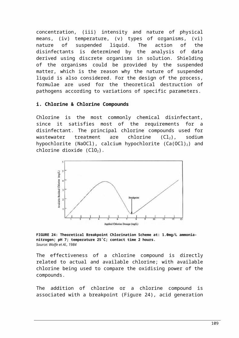
flotation results- Small space requirement
regimes- High energy consumption
Centrifugal thickening
- Good results - Polymer may be required- High maintenance cost- High energy demand
Rotary drum thickening
- Good results - Limited use- Compulsory polymer addition
Source: Skoula &Fatta, 2004
A9c. Dewatering
Dewatering follows thickening, and allows further reduction of the water content in sludge. Portion of dry matter in dewatered sludge can be up to 30%. A table of comparison of the dewatering methods available follows after the brief descriptions of the methods (Table 55).
The main reasons, for which dewatering takes place are:- Substantial reduction in cost of handling sludge: reduction
of volume- Dewatered sludge is much easier to handle.- Removal of excess moisture increases the calorific value;
necessary before incineration- Removal of excess moisture could be associated with
reduction in odour- Dewatering is required prior disposal to landfills and
biosolids in monofills: reduction of leachate production
As other methods, dewatering too has several of options:
Drying bed: this is one of the simplest techniques for dewatering sewage sludge. Used mainly where large and inexpensive area of land is available, and where local climate is favourable (making the technique less favourable in cold climates). There are five types of drying beds used: (i) conventional sand, (ii) paved, (iii) artificial media, (iv) vacuum-assisted and (v) solar.
Centrifuging: is a mechanical process, using centrifugal forced to separate thickened sludge from the centrifugate. They are used in dewatering applications because of their small size, high throughput capacity, and simple operation. The most commonly types used are solid-bowl and basket centrifuges. The process can result to increase in dry matter of 15-25%. An additional increase of 5% can be achieved by the use of a high performance centrifuge.
Filter belt: The sludge is mixed with a polymer, and then dewatered on the same principle as gravity belt thickening, but pressed between two belts. The pressure at which the sludge is applied to varies with the machine (low, medium, high). According to the pressure used and the sludge to be dewatered, the dry matter level
109

can increase up to 10-20%. A combination of filter belts with gravity belt thickening is also possible.
Filter press: Generally, with this method it is possible to reach high dewatering level (30-45%). The types of filter presses commonly used are plate and frame filter presses. Conventional filter presses consist of rows of vertical plates between which sludge is injected under pressure. Before the plates are separated, the filtrate is collected, and the sludge cake falls and collected. To improve dewatering rate, membranes are placed between plates and filled with water. Preliminary conditioning is commonly required with salts or lime. The two types most commonly used are fixed-volume and variable-volume recessed plate filter presses.
Reed beds: are primarily used for wastewater treatment plants of capacity up to 0.2 m3/s. In appearance, they are similar to subsurface flow constructed wetlands, consisting of channels or trenches filled with sand or rock for support of emergent vegetation providing pathway for continuous drainage of water from sludge layer. As plants grow, they provide movement to under-drains by creation of pathways. Additionally, plants absorb water from sludge and oxygen transfer to the roots of plants assists biological stabilisation and mineralization of the sludge.
Drying lagoons: usually used as substitute for drying beds. Lagoons however, are not suitable for dewatering untreated or limed sludge, or sludge with high-strength supernatant, due to odour and nuisance potential. Climate affects the performance of the lagoons; precipitation and low temperature inhibiting dewatering; high evaporation rates encouraging dewatering. Increasingly stringent environmental and groundwater regulations, limit dewatering by subsurface drainage and percolation.
TABLE 55: Comparison of dewatering processesDewatering Advantages Disadvantages
Drying beds
- Small amount of operator attention and skills required- Functions round the year- Low operation costs- Higher solids content than mechanical methods- Low energy consumption- Less sensitive to sludge variability
- Land requirement- Weather dependency- Risk of odours- Sludge removal is labour intensive- Requires stabilised sludge
Centrifuging
- Continuous operation- High installed capacity to building area ratio- Fast start up and shutdown capabilities- Good odour containment- Production of a relatively dry sludge cake
- Specialised maintenance- Sludge texture- Noise- High energy consumption- High investment costs
Filter belt - Low energy requirements- Relatively low capital and operating
- Limited water content reduction- Cleaning water consumption
110

costs- Less complex mechanically and easier to maintain- Continuous operation- Easy to perform
- Supervision necessary- High odour potential- Highly sensitive to incoming sludge feed characteristics
Filter press
- High water content reduction- Structure of the sludge- Possible automation
- Batch operation- Low productivity- Consumption of mineral conditioner- Supervision necessary- High investment cost- High labour cost
Reed beds - Low cost- Easy to operate- Environmentally safe- High level of bacterial and viral removal- Reduction of suspended solids- Reduction of nitrogen concentrations- Removal of metals
Drying lagoons
- Low energy consumption- No addition of chemicals- Organic matter is further stabilised- Low capital cost where land is available- Least amount of skill required for operation
- Design requires consideration of climate effects- Potential for odour and vector problems- Potential for groundwater pollution- More land-intensive than mechanical methods
Source: Skoula &Fatta, 2004
A9d. Stabilisation/ Disinfection
The aim of stabilisation is the reduction of fermentation of putrescible matter in sludge and odour emissions; and disinfection, is the removal of pathogens. Success of these processes is associated with the effects of stabilisation on the volatile or organic fraction of solids and biosolids. Biological reduction of volatile content and addition of chemicals to solids, control the elimination of these nuisance conditions by rendering them unsuitable for microorganisms to survive. Additional aims to stabilisation, are volume reduction, methane production (usable gas), and improving dewaterability of sludge.
Aerobic digestion: aeration of sludge in open basins, allows the direct oxidation of any biodegradable matter, with production of new cellular matter and its subsequent oxidation. Generally, aerobic digestion is used for the treatment of sludges of relatively low solids concentration. While organic mater is being degraded, there is a generation of heat and temperature can exceed 70˚C under the right conditions. High temperatures around 50-60˚C and residence times of typically 5-6 days, allow the destruction of most harmful organisms. Under these conditions, the reduction of volatile matter is around 40%.
Anaerobic digestion (methanisation): has the aim of reducing, stabilising and partially disinfecting the volumes of sludge being
111
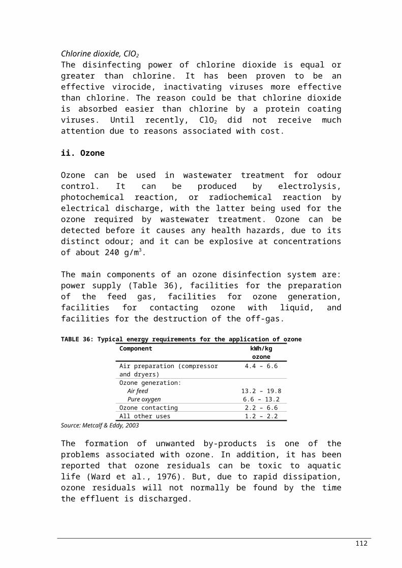
treated. Through this process, organic matter is fermented by bacteria in the absence of free oxygen. For this to occur, sludge is confined in a vessel at 35˚C. The three main phases of the process are: hydrolysis (breakdown of macromolecules to smaller components), acidogenesis (production of acidic compound from the small components), and methanogenesis (carbon dioxide and methane generation). Often, the biogas produced (the mixture of carbon dioxide and methane) is used in boilers to maintain the temperature, or even produce electricity for the plant. To guarantee good stabilisation and disinfection, it is recommended that the sludge remains in the digested for more than 20 days. Altering the medium or the temperature, leads to other similar techniques.
Long-term storage: of sludge allows (1) regulation of sludge flows to agriculture and (2) homogenisation of its composition. Odours, increase of dry matter, reduction of organic matter and reduction of nitrogen (converted to ammonium and ammonia) are some of the characteristics of the sludge after some time. Disinfection arises after a long-term storage, as bacteria and viruses reduce, but parasites’ numbers are not affected. Sufficient level of disinfection cannot be achieved in cold climates regardless the periods held.
Composting: this is a cost effective, environmentally sound alternative of stabilisation. Through biological degradation organic material stabilises; this is the process of composting. Through the process, approximately 20-30% of organic matter is converted to carbon dioxide and water, and temperature rises to 50-70˚C (pasteurization range). As a result, enteric pathogenic organisms are destroyed. If the result of composting follows the limitations given for particular constituents, treated sludge can be used as soil conditioner for applications in agriculture or horticulture. Even though aerobic composting is the most commonly used, composting can be achieved under aerobic and anaerobic conditions. Aerobic conditions accelerate material decomposition and the temperature rise is greater (better pathogen destruction).
Sludge generated after composting has a high agricultural value since it has a good level of disinfection and is stabilised (i.e. reduced odours) which in addition to the humus like aspect, it is more acceptable and easier to use. Through composting, the reduction of water content can reach values greater than 60% of dry matter, allowing easier handling.
The types of composting are three:1. Windrow: sludge is mixed with a bulking agent and set out to piles. Mechanical turning of the composting material introduces air and prevents excessive rise in temperature. This method requires large land area.
112

2. Aerated static piles: here the sludge is mixed with bulking agent, but laid over perforated pipes or on a floor through which air is blown.3. Vessel systems: once the sludge is mixed with the bulking agent, sludge is injected at the top of a vessel, where harrow permits an equal repartition. Air is injected in the lower part of the vessel, where the end product is also extracted.
Alkaline stabilisation: is used for the elimination of the nuisance conditions in sludge. This is achieved by the use of alkaline material to provide sludge with conditions that are unsuitable for microorganisms to survive. More accurately, sufficient lime (or sodium-, or potassium-, or magnesium hydroxide) is added to untreated sludge to raise pH to 12 or higher. The resulting sludge, will not putrefy, create odours or pose a health hazard. Simultaneously, viruses, bacteria and other microorganisms present can be inactivated. It should be noticed though that high concentrations of sodium and potassium inhibit plant growth, and should not be therefore be used in cases where sludge is to be used as fertilizer. Additionally, magnesium hydroxide is in comparison to calcium hydroxide (lime) more expensive.
Non-alkanine chemicals can also be used in chemical stabilisation, but are restricted; they are used only sporadically mainly due to their high cost. Chemicals used include per-acetic acid, formalin, quaternary ammonium compounds, sodium hypochlorite, sodium nitrate, ozone potassium permanganate, potassium ferate, hydrogen peroxide and nitrite acid.
The most commonly used methods described, are compared in the table that follows (Table 56)
TABLE 56: Comparison of most commonly used stabilisation processesStabilisation Advantages Disadvantages
Aerobic digestion
- Simple to operate - No production of usable gas- Energy intensive process- High operation cost- Sufficient odour reduction
Anaerobic digestion
- Production of methane- Resulting biosolids can be applied to land
- Skilled operators required- Sufficient odour reduction
Composting
- A variety of solids and biosolids can be composted
- Need of bulking agent addition- Need for odour control
Alkaline stabilisation
- Rich soil-like resulting product with substantial reduction in pathogens
- Increase of the product mass (addition of chemicals)- Fair attenuation of putrefaction- Fair reduction of odour- Cost of chemicals
Source: Skoula &Fatta, 2004
Pasteurisation: is the process of heating the sludge for a short period (about 30 minutes) to a temperature of 70-80˚C, allowing the reduction of the pathogens in the sludge (but cannot be
113

considered a stabilisation process by itself). Pasteurisation may not be cost-effective for small plants, due to the high capital costs involved (estimation of 149 €/t-TS).
Irradiation: can also be used for the reduction of the microorganisms present in sludge. Typical radiation doses for inactivation of enterobacteriaceae are 1-2 kGy; for viruses and coliforms 15-20 kGy; and for typical sludge disinfection 3 kGy. The cost of radiation is 92 €/t-TS.
A9e. Heat Drying
Through heat drying, water is evaporated from sludge, reducing the moisture content for biosolids to levels lower than conventional dewatering methods. Reduction in transportation costs, additional pathogen reduction, improvements in storage capability and marketability are among the advantages introduced by the method. Additionally is can be applied for increase in calorific value of the sludge before thermal oxidation and for spreading with application of similar techniques as mineral fertilizers.
Heat can be applied to sludge directly or indirectly, to different temperatures. Attention should be paid in very high temperatures (>300˚C) where dioxin and furan compounds can be formed. Intensive contact between gas and sludge material is crucial for direct heating, with the most important types of dryers being revolving drum gas and fluidized bed dryer. For indirect heating, the heat is transferred to the material via heat conduction through a heat transfer surface, i.e. sludge is not in contact with the heating medium.
DM level reached can be between 35 and 90%, with partial drying enabling 30-45% to be reached, where auto-combust of the sludge is possible. Re-growth of bacteria is inhibited, due to the reduction of moisture level. In comparison to dewatering, at the basis of volume of extracted water (tEW), energy requirements for drying are much higher, but could be reduced to a great extent if an energy source is available on site. Consequently, drying takes place after dewatering.
A9f. Recently developed methods
i. Wet OxidationWith the use of strong oxidants and/or aggressive reaction conditions, sludge is disintegrated, to make the organic matter soluble and therefore increase biodegradability. Simultaneously, complete oxidation of CO2 and water leads to elimination of considerable amount of matter. Matter which is soluble and not
114

completely oxidised can degrade biologically. As a result, sludge is changed in three main products:a) Liquid phase : contains easily degradable organic matter which
can be easily treated when sent back to the start of the wastewater treatment.
b) Clean combustion gases : the low temperatures of the process prevent the generation of compounds such as PCDD/F; no treatment required. Additionally, due to the wet environment, dust is not released to the atmosphere.
c) Mineral residues in liquid phase : need treatment
Heavy metals concentrate in the solid residue except mercury which is found in the gas; and organic pollutants are broken down. In most cases thickening provides the necessary pre-treatment required before wet oxidation.
Wet oxidation processes known are two. In VerTech process, sludge is treated in a 1280m deep hollow shaft, with pure oxygen being injected at 300 and 900 m. In the concentric shaft tubes, autothermal operation takes place: heat is exchanged from the outcoming sludge passing the outer tube to the fresh sludge in the inner tube. The process reaches efficiency 20% solubilisation and 75% complete oxidation and has been operating in Netherlands since 1994.
The other process is Bayer-Loprox, which oxidises waste activated sludge under acidic conditions with the use of a catalyst. Retention time in the reactor is 1-3 hours, and oxidation can take place at temperatures below 200˚C, and pressures of 500-2000 kPa (due to the presence of the catalyst). Approximately 90% of solids are solubilised, of which 70% are solubilised completely, with the remaining organic compounds being easily degradable.
ii. BEVAP (Biological Evaporation)This is a technology where sludge water is removed by biologically produced heat. Bulking material is mixed into primary and secondary sludge, reaching 50% dry matter content. Addition of rapid biodegradable carbon source takes place as source of extra energy input depending on energy content, biodegradability and dry matter content. Sludge is dried by the biological degradation and the carbon source.
iii. DisintegrationDisintegration of microbial cells (which can take place mechanically, thermo chemically and biologically) eliminates or facilitates the rate-limiting step in biological digestion; the step of hydrolysis. Consequently, the rate of digestion can increase and digestion efficiency improved.
115

iv. PyrolisisDuring the process of pyrolisis, sludge is dewatered, dried and heated to 400-700˚C in an environment of low oxygen concentration. The inert portion of sludge forms a material similar to coke, whereas parts of the organic fraction gasify at these temperatures and can be used as source for energy. Additionally, when gas is cooled condensation of oil takes place, which can also be used for energy production.
The advantages of the process are reduced gas emissions, practically no emission of PCDD/F and possible separation and volatilisation of minerals. In addition, the size of the unit is reduced and so are the costs, due to the low temperature of the process. At the present, the available techniques are developed by German (e.g. Siemens, Thermoselect) and French (e.g. Nexus, Thide) firms.
v. GasificationThis is a thermal process during which a combustible material is converted with air or oxygen to an inflammable and inert residue: at temperatures of at least 900˚C, a variant of starved air combustion takes place. As the sludge is added, sub-stoichiometric quantities of oxygen or air are injected, to allow combustion of carbon to CO2, which will further react with solid carbon to form CO. Simultaneously, water-shift reactions generate H2 from carbon and H2O. The main constituents of the gas formed from gasification of sludge are Co, H2, N2, CO2, CH4 and H2S. When sludge is gasified with oxygen (most common), 55-60% of the gas is N2, with calorific value of 4-5 MJ/Nm3. Some residue is also formed by the conventional gasification containing some volatile material.
Complete destruction of all pathogens and viruses, control of heavy metals, destruction of organochlorine compounds and odour control, are the advantages demonstrated through pilot projects (new method, not well documented).
116

Bibliography and ReferencesAngelakis, N.A., Bontoux L., Lavaroza V., (2003) Challenges and
Prospectives for Water Recycling and Reuse in EU Countries, Water Science and Technology: Water Supply; Vol 3 No4 Pp 59-68, IWA Publishing
Asano, T. (1998) Wastewater Reclamation, Recycling, And Reuse: An Introduction in Wastewater Reclamation and Reuse, T. Asano (Ed.), Lancaster, Pennsylvania, Technomic Publishing Company, 1998: 1-56
Blumenthal U.J., Peasey A., Ruiz-Palacios G., Mara D.D., (2000) Guidelines for Wastewater reuse in agriculture and aquaculture: recommended revisions based on new research evidence, Task No 68 Part 1, WELL
Butler D. and Smith S., (2003) ENV5 Wastewater Treatment & ENV15 Advanced Wastewater Treatment, MSc Environmental Engineering course notes, Imperial College, London
Commission on Geosciences, Environment, and Resources (1996) Use of Reclaimed Water and Sludge in Food Crop Production, National Academy Press, Washington, D.C.,
Council of European Union (1991) Council Directive 91/271/EEC of 21 May 1991 concerning Urban Waste Water Treatment
Council of European Union (1998) Council Directive 98/83/EC of 3 November 1998 on the quality of water intended for human consumption
Cranfield University (2001) Urban Water Recycling Information Pack, UK
Culp, G., Wesner, G., Willians, R., Hughes, M. (1980) Wastewater reuse and recycling technology, Noyes Data Corporation, Park Ridge, New Jersey (Office Water Research & Technology, OWRT/RU-79-1,2)
Droste, L. R. (1997) Theory and Practice of Water and Wastewater Treatment, John Wiley & Sons, Inc., New York
Eckenfelder W.W. Jnr (2000) Industrial Water Pollution Control, 3rd Edition, Mcgraw-Hill, Boston, MA
EUREU (2001) Water Reuse, EUREAU Position Paper EU1-01-A63 (3)
Grandy, L.P.C. Jr., Daigger T.G., Lim C.H., Biological Wastewater Treatment, Marcel Dekker, Inc., New York, 2nd Edition, 1999
Harding, R.W. (2003) Reuse of treated Wastewater: Is this a Case of “Here be Dragons”?, Southern Waters Ecological Research and Consulting
IRCWD (1985) The Engelberg Report, Switzerland
117

Junger, J.F. (2000) European research on treated wastewater reuse in agriculture. Workshop “The reuse of urban wastewater in agriculture”, Bologna, Italy
Kretschmer, N., Ribbe L., Gaese H., Wastewater Reuse for Agriculture, Technology Resource Management & Development – Scientific Contributions for Sustainable Development, Vol.2
Kugelman, I.J. (1976) Status Of Advanced Waste Treatment, H.W. Gehm And J.I. Bregman (Eds.) Handbook Of Water Resources And Pollution Control, Van Nostrand, New York
Lazarova, V. (2001) Role of water reuse in enhancing integrated water management in Europe, Final Report of the EU project CatchWater, V. Lazarova (Ed.), ONDEO, Paris, France.
Mancl, K. Food, Agricultural and Biological Engineering, AEX-768-96, http://ohioline.osu.edu/aex-fact/0768.html (21-Oct-04)
Metcalf & Eddy (2003) Wastewater Engineering, Treatment and Reuse, 4th Edition, Mcgraw-Hill, New York
Nolte and Associates in association with HYA Consulting Engineers, Bookman Edmonston Engineering Inc. Sacramento (1994) County Water Reclamation Study, prepared for the Sacramento Regional County Sanitation District
Pettygrove, G.S. and T. Asano, (1985), Irrigation with reclaimed municipal wastewater - a guidance manual, Lewis Publishers, Inc., Chelsea, MI. 498 pp.
Randall, C.W., Barnard J.L. And Stensel H.D. (1992) Design and Retrofit or Wastewater Treatment Plants for Biological Nutrient Removal, Technomic Publishing Co., Lancaster, PA
Reynolds & Richards (1996) Unit Operations and Processes in Environmental Engineering, 2nd Edition, ITP Publishing, Boston
Richard, D., Scroggs, L., Anderson, M., Mingee, T. (1996) Using Sodium Hypochlorite for Disinfection of Reclaimed Wastewater: Design and Operational Issues, Proceedings from Water Environment Specialty Conference: Disinfecting Wastewater for Discharge and Reuse. Portland, Oregon
Rittmann, D.D (1997), "Can You Have Your Cake And Eat It Too" With Chlorine Dioxide? WATER/Engineering & Management, April
Sedlak, R.I. (1991) Phosphorus and Nitrogen Removal from Municipal Wastewater, 2nd Edition, The Soap and Detergent Association, Lewis Publishers, New York
Skoula, I., Fatta D., Villanueva A., (2004) Handling, Utilisation and Disposal of Sewage Sludge in Europe, Working Document, European Environment Agency, Copenhagen, (In Press).
118

Stephenson, T., Judd S., Jefferson B., Brindle K. (2000) Membrane Bioreactors for Wastewater Treatment, IWA Publishing, London
Strauss, M. (2000) Human Waste (Excreta and Wastewater) Reuse, EAWAG/ SANDEC, Switzerland
Strauss, M. (2001), Reuse of Urban Wastewater and Human Excreta, ETC - Urban Agriculture Programme, Leusden, The Netherlands.
Seckler, D., Amarasinghe U., Molden D., De Silva R., Barker R., (2000) World Water Demand And Supply, 1990-2025: Scenarios And Issues 2000, International Water Management Institute, 19 Research Report
Tchobanoglous, G., Crites R., (1998), Small and Decentralized Wastewater Management Systems, McGraw-Hill College
Tsagarakis, KP, DD Mara, NJ Horan and AN Angelakis (2000) Small municipal wastewater treatment plants in Greece, Water Science and Technology Vol 41 No 1 pp 41–48 © IWA Publishing 2000
UNEP (2002) Are Shortages A Long-Range Outlook in Mediterranean Europe, Plan Bleu
UNEP (2003) Mediterranean Commission for Sustainable Development, Results of the Fiugi Forum on “Advances of Water Demand Management in the Mediterranean – Findings and Recommendations, Plan Bleu
UNEP (2002) Progress towards Water Demand Management in the Mediterranean Region – Contemporary Trends and Water Demand Change Perspectives in the Mediterranean Countries, Plan Bleu
UNEP (1997) International Environmental Technology Centre, Source Book of Alternative Technologies for Freshwater Augmentation in Latin America and the Caribbean, Washington D.C.
UNEP, Division of Technology Industry and Economics, International Environmental Technology Centre, (2000), International Source Book on Environmentally Sound Technologies for Wastewater and Stormwater Management, Osaka
University of Newcastle upon Tyne, School of Civil Engineering and Geosciences (2003), Hydroinformatics and Management Systems, U.K.
Urkiaga, A., Fuentes L. (2004) Best Available Technologies for Water Reuse and Recycling. Needed Steps to Obtain the General Implementation of Water Reuse, Fundaciόn Gaiker, Parque Tecnolόgico De Bizkaia, Spain
USEPA (2004), Guidelines for Water Reuse, EPA/625/R-04/108
119

U.S. Environmental Protection Agency (1992), Process Design Manual: Guidelines for Water Reuse (Report No. EPA-625/R-92-004)
WEF & ASCE (1992) Design of Municipal Wastewater Treatment Plants, Vol.1, WEF
WEF & ASCE (1998) Design of Municipal Wastewater Treatment Plants, 4th Edition, WEF Manual of Practice MOP-8 Volume 3
WHO (1996) Analysis of Wastewater for Use in Agriculture – A Laboratory Manual of Parasitological and Bacteriological Techniques
WHO (1989) Guidelines for the safe use of wastewater and excreta in agriculture and aquaculture: Measures for public health protection
WHO/UNEP (1997) Water Pollution Control – A Guide to the Use of Water Quality Management Principles
Young, J.C. (1991) Factors affecting the design and Performance of Upflow Anaerobic Filters, Water Science and Technology, vol.24, no.8, pp133-155.
Zhou, H., Smith D.W. (2002) Advanced technologies in water and wastewater treatment, J. Environ. Eng. Sci. 1: 247-264 (2002), NRC Canada
Zytner G. R. (2003) ENGG3590 Water Quality Course Notes, School of Engineering University of Guelph, California
120