Embed Size (px)
Citation preview
Physica C 468 (2008) 1579–1582
Contents lists available at ScienceDirect
Physica C
journal homepage: www.elsevier .com/ locate/physc
Development of scribing process of coated conductors for reduction of AC losses
K. Suzuki a,d,*, M. Yoshizumi a, T. Izumi a, Y. Shiohara a, M. Iwakuma b, A. Ibi c, S. Miyata c, Y. Yamada c
a Superconductivity Research Laboratory, ISTEC, 1-10-13, Shinonome, Koto-Ku, Tokyo 135-0062, Japanb Research Institute of Superconductor Science and Systems, Kyushu University, 6-10-1, Hakozaki, Higashi-Ku, Fukuoka, 812-8581, Japanc Superconductivity Research Laboratory, ISTEC, Nagoya Coated Conductor Center, 2-4-1, Mutsuno, Atsuta-Ku, Nagoya 456-8587, Japand Railway Technical Research Institute, 2-8-38, Hikari-Cho, Kokubunji-Shi, Tokyo 185-8540, Japan
a r t i c l e i n f o a b s t r a c t
Article history:Available online 25 May 2008
PACS:81.20.Wk74.25.Ha74.25.Sv74.25.�q74.72.Bk
Keywords:AC lossScribingMultifilamentAnnealCoated conductor
0921-4534/$ - see front matter � 2008 Elsevier B.V. Adoi:10.1016/j.physc.2008.05.076
* Corresponding author. Address: Railway TechnicHikari-Cho, Kokubunji-Shi, Tokyo 185-8540, Japan. Te42 573 7360.
E-mail address: [email protected] (K. Suzuki).
Coated conductors (CCs) are prospective for electric power applications intended for not only better costperformance but also high critical current density (Jc) under magnetic fields comparing with Bi2Sr2Ca2-Cu3Oy (BSCCO) tapes. Furthermore, they also have a possibility to reduce AC losses by various methodsof post-treatments since the CCs are of a laminated structure with the insulating buffer layers. Multifil-amentation by narrowing the tape width is quite effective to reduce the AC losses and therefore thisapproach is valid for the standard process to fabricate practical CCs with an appropriate architecture.In this study, we developed a tape scribing technique applying a technique of YAG laser with/withoutchemical etching to control the filament width in YBa2Cu3Oy (YBCO) CCs for the multifilament. The ACloss was reducible to one-twentieth by 20-multifilament structure in a short sample test, and to one-third by 3-multifilament structure in the coil using 28 m long tapes in total.The authors measured the resistance between the filaments at 60–300 K after post-treatment to investi-gate the effective bridged materials, which is essential for decoupling of the filaments. We improved theresistance value between the filaments at liquid nitrogen temperature up to the order of 10 X/cm usingthe YAG laser with high-temperature oxygen anneals. Furthermore, the resistance over 106 X/cm wasevident by the combination of laser scribing and chemical etching, which is much higher than therequirements of all the applications.
� 2008 Elsevier B.V. All rights reserved.
1. Introduction
Coated conductors (CCs) are promising new high-temperaturesuperconductor (HTS) tapes applicable in the near future. Theyhave some advantages such as high Jc-B property, high mechanicalstrength, low production cost, etc., compared with BSCCO wires[1]. Simplicity to form multifilament structure is another potentialadvantage.
It is important to produce multifilament structure to reduce theAC loss.
Various researches have investigated in their attempts to in-crease the number of filaments in short samples as referred in[2–6], however the total critical current (Ic) values of the multifil-ament CCs is far behind from the practical requirement.
In addition, it is also vital to obtain high electric resistances be-tween the filaments where longer tapes used for the AC applica-tions. Some authors suggested oxygen annealing at 550 �C [6] or
ll rights reserved.
al Research Institute, 2-8-38,l.: +81 42 573 7297; fax: +81
700 �C [7,8] is effective to increase the resistance values due tooxidizing dross between the filaments. However, these electricresistance values (the order of 10�3–101 X/cm) are low enoughfor to reduce the AC loss in the case of transformer applications.The required value of electric resistance value would be higherthan 103 X/cm if their coils were wound by a certain windingmethod [9].
Most of the researchers have reported the results on the AC lossby their investigations using short samples. Although high electricresistance easily obtainable in the short samples, it is difficultwhen longer tapes are used. In addition, these have never beenthe repute on the reduction of the AC loss in coil shape, even ifthe coil was wound by the multifilament tapes.
In this study, we have developed two scribing processes usingYBCO tapes. One is a scribing process by a YAG laser to producemultifilament structures in short samples, and another is a combi-nation of the scribing process by a YAG laser with the chemicaletching technique to increase the electric resistance between thefilaments to reduce the AC loss in coil using longer tapes. Then,we produced two different kinds of coils wound using non-scribedtapes and scribed tapes. We measured the AC losses in these coilsby the electrical method.

Table 2Ica (A) values before and after scribing at 77 K, s.f
Samplename
Ic beforescribing
Ic afterscribing
The numberof filaments
Dimension(cm � cm)
A1 260 230 20 10 � 1A2 257 228 20 10 � 1
a Critical currents were determined at 10�6 (V/cm).
0
50
100
150
200
250
1 2 3 4 5 6 7 8 9 10 11 12 13 14 15 16 17 18 19 20
The number of filaments
Ic (
A)
at 7
7K
0
10
20
30
40
50
Ic d
efer
ence
in n
eigh
bor
fila
men
ts (
A)
Ic (A)Ic deference (A)
Fig. 2. Ic values after 20-multifilament scribed tapes when reducing the filamentsone by one.
1580 K. Suzuki et al. / Physica C 468 (2008) 1579–1582
2. YAG laser process in a short sample
YAG laser has Nd:YAG crystals for the active medium and thelaser diode for pumping the light source. The laser has the wave-length of 1064 nm. The wavelength is changeable to 355 nm (thethird harmonic generation) by passing thorough nonlinear opticalcrystals. The YAG laser scribing system is capable to treat for500 m long tape by the reel-to-reel (RTR) system. The specifica-tions of the system used in this study are self-explanatory as re-ferred in [8].
2.1. Sample preparation
All samples before scribing were cut from one YBCO long tape.No large defects in the tape were apparent by the non-destructiveevaluation technique using a hall sensor array [10]. Processingparameters are listed in Table 1, and a photograph of 20-multifila-ment YBCO tapes by a YAG laser process is shown in Fig. 1.
2.2. Critical current measurement
The Ic values by DC four-probe method before and after scribingwere listed in Table 2.
The 20-multifilament tape revealed 10% smaller Ic value thanthat before scribing. According to the scribed width (20 lm), thereduction of Ic value should be estimated as around 5%. The largerIc reduction in the real 20-multifilament tape than the estimationmight be caused by the effect of the width or the reduction of oxy-gen content near the ditch.
It was difficult to measure Ic of each filaments whose widthwere approximately 500 lm, however, the each Ic values was eval-uated by the following procedure, after Ic measurement of the 20-multifilament tape, one filament was cut by the scalpel in thetransversal direction. Then we measured Ic value of the tape with
Table 1Parameters in two processes
Process YAG laser YAG laser with chemical etching
Repetition rate (kHz) 30 10Energy (W) 2.4 3.6Tape moving rate (mm/sec) 6 6Laser spot diameter (lm) 20 20Gap between trace lines (lm) – 300The number of filaments 20 3Dimension (cm � cm) 1 � 5–10 1 � 200–1500Tape type IBAD-PLDa IBAD-PLDa
a These tapes were fabricated by SRL Nagoya coated conductor center.
Fig. 1. Picture of 20-multifilament YBCO tapes by a YAG laser process.
19 filaments. The Ic difference should be the Ic value of the filamentcut just before the measurement. Repeating this manner, total Ic
and individual Ic values of 1–20 filaments were obtained as shownin Fig. 2. The differences of the measurements were similar. Itmeans that the Ic values of each filament were almost uniform ex-cept the filament number 1, 2 and 20.
2.3. Magnetization loss measurement
The Ic values of the tapes, which were used for AC loss evalua-tion, were listed in Table 3. R1–R3 and B1–B3 tapes were stackedfor AC loss measurements. We measured the AC losses applyinga saddled pickup method [11] at 77 K. Fig. 3 shows the AC lossdependence on the magnetic field amplitude. The AC loss of 20-multifilament tapes reduced to the degree of 1/20 compared tothat of single-filament tape in the region of the large field ampli-tude, where the effective penetration field went into the centerof the tapes. The result could verify the theory that the AC loss re-duced to 1/20 by forming 20-multifilament structure [12,13].
Table 3Ica (A) values at 77 K, s.f. for AC magnetization loss measurement
Samplename
Ic beforescribing
Ic afterscribing
Scribing The numberof filaments
Dimension(cm � cm)
B1 N/A 225 Yes 20 5 � 1B2 N/A 222 Yes 20 5 � 1B3 N/A 218 Yes 20 5 � 1R1 271 N/A No 1 5 � 1R2 267 N/A No 1 5 � 1R3 260 N/A No 1 5 � 1
a Critical currents were determined at 10�6 (V/cm).

103
104
105
106
107
108
10-3 10-2 10-1 100
AcLo
ss(J
/m3 C
ycle
)
Field Amplitude (T)
20 - filaments
Reference
Åó77K
1 / 20
3
10
8
- - -- - -
(l
20 - filaments
Reference
77K
1 / 20
Fig. 3. AC loss comparison between non-scribed and 20-multifilament tapes, ACloss was reduced as expected.
1.0E+00
1.0E+01
1.0E+02
1.0E+03
1.0E+04
1.0E+05
1.0E+06
1.0E+07
Sample1 Sample2 Sample3 Sample4
Res
ista
nce
(ohm
/cm
)@30
0K
Between left and right fila.
Between left and centre fila.
Between centre and left fila.
0
20
40
60
80
100
120
140
Sample1 Sample2 Sample3 Sample4
Ic(A
)@77
Ks.
f.
0%
20%
40%
60%
80%
100%
120%Left fila.Center fila.Right fila.Change rate
Fig. 4. Characteristics of 3-multifilament tapes by a YAG laser with chemicaletching process. (a) Each Ic values. (b) Resistance values between filaments.
K. Suzuki et al. / Physica C 468 (2008) 1579–1582 1581
The theory for the decrease to 1/N of magnetization losses in N-filament tapes was conducted by Irie–Yamafuji model [13] orBrandt–Indenbom model [14], assuming that Jc distributions werehomogenous in the width direction. However, actual CCs havesome Jc distribution in the width direction (see Fig. 2). It meansthat the distribution level of Ic value in Fig. 2 does not have sostrong influence to the loss.
3. YAG laser with chemical etching process for a low AC loss coilusing long tapes
We developed such a process for CCs with extremely high elec-tric resistance between filaments for reducing AC losses even in thelong tape.
3.1. Sample preparation
A polyimide film was pasted on top of each YBCO tapes. Thetapes were irradiated by the YAG laser through the polyimide film,while irradiated directly in YAG laser process (see Section 2). Forthe prevention of short circuit between filaments next to eachother, gap width between the filaments increased; the processingparameters are shown in Table 1. Two narrow filaments with300 lm in width were formed between 3 wide filaments by the la-ser scribing. The narrow filaments were removed by etching toform a 3-multifilament structure. The silver layer and YBCO layerwere etched by mixed solution of hydrogen peroxide (H2O2) andammonia (NH3) and nitric acid (HNO3) solution, respectively. Afteretching operations, the etchant were rinsed out of tapes not to de-grade superconducting properties by deionized water. Residualwater was removed in a furnace. The gaps between filaments wereapproximately 500 lm width, which were made wider by etchingpenetration. YBCO and silver near side edges were also etchedapproximately 300 lm due to penetration, which suppress theshort circuit as well. Multifilament technique was commonlyapplicable, however, delamination problem between oxide layerswas found to be addressed. D.C. van der Laan reports low delami-nation strength in slit MOD-RABiTS CCs in liquid nitrogen cooling,and their proposed technique against delamination to laminatethin copper tapes by solder on both sides, like sandwich [15].The copper lamination method was not suitable for these multifil-ament tapes, because of the short circuit by the copper and solder.
Therefore, we have to develop another way to solve this problem. Itwas evident that the oxygen annealing at high temperature couldprevent delaminating and solved this problem [16].
3.2. Critical current measurement
The Ic values of filaments from four samples 1–4 were measuredby the DC four-probe method at 77 K as shown in Fig. 4a.
The amount of YBCO lost as the result of laser ablation andchemical etching is about 16% for the 3-multifilament tapes. Thetotal Ic values of 3-multifilament tapes decrease in about 20% ofthat before scribing.
3.3. Resistance between filaments measurement
The resistance values between the filaments of the four samplesmeasured by the DC two-probe method at 300 K are shown in Fig.4b.
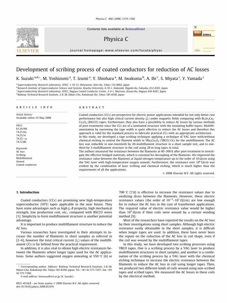
We likewise measured the resistance values between the fila-ments of a short sample by the DC four-probe method at 60–300 K, which are shown in Fig. 5. Temperature dependence ofresistance in this process was negative since the bridged materials
10mm 3fila (J/cycle)No slit (J/cycle)
Ac
Loss
(J/c
ycle
)
I (A)
1/3Reduction
10 -3
10 -2
10 -1
10 0
101 10 2
10mm 3fila (J/cycle)No slit (J/cycle)10mm 3fila (J/cycle)No slit (J/cycle)
Ac
Loss
(J/c
ycle
)
I (A)
1/3Reduction
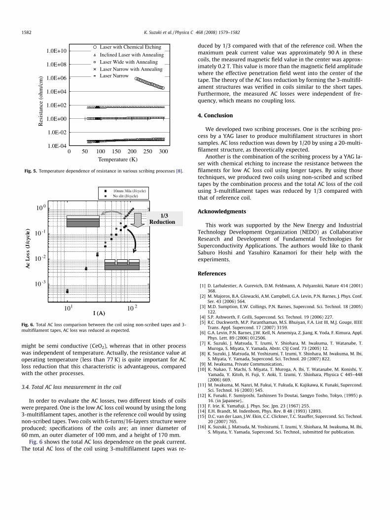
Fig. 6. Total AC loss comparison between the coil using non-scribed tapes and 3-multifilament tapes, AC loss was reduced as expected.
1.0E-04
1.0E-02
1.0E+00
1.0E+02
1.0E+04
1.0E+06
1.0E+08
1.0E+10
0 50 100 150 200 250 300Temperature (K)
Res
ista
nce
(ohm
/cm
) Laser with Chemical Etching
Inclined Laser with Annealing Laser Wide with Annealing Laser Narrow with Annealing Laser Narrow
Fig. 5. Temperature dependence of resistance in various scribing processes [8].
1582 K. Suzuki et al. / Physica C 468 (2008) 1579–1582
might be semi conductive (CeO2), whereas that in other processwas independent of temperature. Actually, the resistance value atoperating temperature (less than 77 K) is quite important for ACloss reduction that this characteristic is advantageous, comparedwith the other processes.
3.4. Total AC loss measurement in the coil
In order to evaluate the AC losses, two different kinds of coilswere prepared. One is the low AC loss coil wound by using the long3-multifilament tapes, another is the reference coil would by usingnon-scribed tapes. Two coils with 6-turns/16-layers structure wereproduced; specifications of the coils are; an inner diameter of60 mm, an outer diameter of 100 mm, and a height of 170 mm.
Fig. 6 shows the total AC loss dependence on the peak current.The total AC loss of the coil using 3-multifilament tapes was re-
duced by 1/3 compared with that of the reference coil. When themaximum peak current value was approximately 90 A in thesecoils, the measured magnetic field value in the center was approx-imately 0.2 T. This value is more than the magnetic field amplitudewhere the effective penetration field went into the center of thetape. The theory of the AC loss reduction by forming the 3-multifil-ament structures was verified in coils similar to the short tapes.Furthermore, the measured AC losses were independent of fre-quency, which means no coupling loss.
4. Conclusion
We developed two scribing processes. One is the scribing pro-cess by a YAG laser to produce multifilament structures in shortsamples. AC loss reduction was down by 1/20 by using a 20-multi-filament structure, as theoretically expected.
Another is the combination of the scribing process by a YAG la-ser with chemical etching to increase the resistance between thefilaments for low AC loss coil using longer tapes. By using thosetechniques, we produced two coils using non-scribed and scribedtapes by the combination process and the total AC loss of the coilusing 3-multifilament tapes was reduced by 1/3 compared withthat of reference coil.
Acknowledgments
This work was supported by the New Energy and IndustrialTechnology Development Organization (NEDO) as CollaborativeResearch and Development of Fundamental Technologies forSuperconductivity Applications. The authors would like to thankSaburo Hoshi and Yasuhiro Kanamori for their help with theexperiments.
References
[1] D. Larbalestier, A. Gurevich, D.M. Feldmann, A. Polyanskii, Nature 414 (2001)368.
[2] M. Majoros, B.A. Glowacki, A.M. Campbell, G.A. Levin, P.N. Barnes, J. Phys. Conf.Ser. 43 (2006) 564.
[3] M.D. Sumption, E.W. Collings, P.N. Barnes, Supercond. Sci. Technol. 18 (2005)122.
[4] S.P. Ashworth, F. Grilli, Supercond. Sci. Technol. 19 (2006) 227.[5] R.C. Duckworth, M.P. Paranthaman, M.S. Bhuiyan, F.A. List III, M.J. Gouge, IEEE
Trans. Appl. Supercond. 17 (2007) 3159.[6] G.A. Levin, P.N. Barnes, J.W. Kell, N. Amemiya, Z. Jiang, K. Yoda, F. Kimura, Appl.
Phys. Lett. 89 (2006) 012506.[7] K. Suzuki, J. Matsuda, T. Izumi, Y. Shiohara, M. Iwakuma, T. Watanabe, T.
Muroga, S. Miyata, Y. Yamada, Abstr. CSJ Conf. 73 (2005) 12.[8] K. Suzuki, J. Matsuda, M. Yoshizumi, T. Izumi, Y. Shiohara, M. Iwakuma, M. Ibi,
S. Miyata, Y. Yamada, Supercond. Sci. Technol. 20 (2007) 822.[9] M. Iwakuma, Private Communication..
[10] K. Nakao, T. Machi, S. Miyata, T. Muroga, A. Ibi, T. Watanabe, M. Konishi, Y.Yamada, Y. Kitoh, H. Fuji, Y. Aoki, T. Izumi, Y. Shiohara, Physica C 445–448(2006) 669.
[11] M. Iwakuma, M. Nanri, M. Fukui, Y. Fukuda, K. Kajikawa, K. Funaki, Supercond.Sci. Technol. 16 (2003) 545.
[12] K. Funaki, F. Sumiyoshi, Tashinsen To Doutai, Sangyo Tosho, Tokyo, (1995) p.16. (in Japanese)..
[13] F. Irie, K. Yamafuji, J. Phys. Soc. Jpn. 23 (1967) 255.[14] E.H. Brandt, M. Indenbom, Phys. Rev. B 48 (1993) 12893.[15] D.C. van der Laan, J.W. Ekin, C.C. Clickner, T.C. Stauffer, Supercond. Sci. Technol.
20 (2007) 765.[16] K. Suzuki, J. Matsuda, M. Yoshizumi, T. Izumi, Y. Shiohara, M. Iwakuma, M. Ibi,
S. Miyata, Y. Yamada, Supercond. Sci. Technol., submitted for publication.