Embed Size (px)
Citation preview


DEVELOPMENT OF PREMIUM EFFICIENCY CENTRIFUGAL COMPRESSOR FOR
MIDDLE EAST DISTRICT COOLING APPLICATIONS
International District Cooling ConferenceDubai, 15th of November 2016
Mr Luca PaolellaDaikin Applied Europe V.P. CEO, Engineering & Manufacturing Director

3
Background
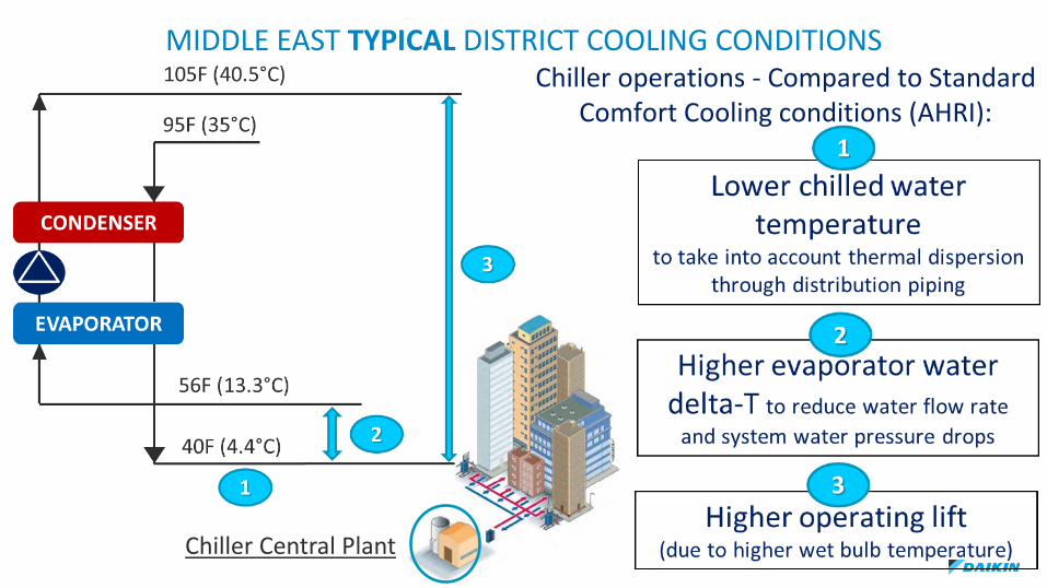
Chiller operations - Compared to Standard Comfort Cooling conditions (AHRI):
MIDDLE EAST TYPICAL DISTRICT COOLING CONDITIONS
Chiller Central Plant

5
MIDDLE EAST TYPICAL DISTRICT COOLING CONDITIONS
Low delta-T syndrome4
Higher Entering cooling water temperature vs design
5
District Cooling plants require also chillers the ability to operate at below typical adverse conditions:
- Forces more chillers to operate at part loads;- Increase in Opex for DC provider since plant
efficiency is reduced;- Impedes full utilization of plant installed capacity.
- In case of failure of a Cooling Tower, the header temperature of water leaving the tower will rise affecting all the chillers;
- During summer, make-up water from utility provider can be as high as 113F / 45degC

6
GLOBAL ENERGY MARKET
The electric energy market price has been growing in the last years even in the Middle East region and
such a growth is expected to continue in the next coming years.
District Cooling investments must look at future energy cost as well.As energy demands and costs rise, District Cooling plants for offices,industry and homes need to be increasingly efficient, reliable andsustainable
Today Power Rate in Dubai: 0.13 USD/kWh(Source: DEWA)

7
ENVIRONMENT
Several regulations are introducing mandatory and stringent requirements on the Energy-Related-Products’ design in order to achieve
challenging global targets of CO2 reduction in the next decades, as per the agreements from Global Climate Conferences- Latest MOP28 Kigali (Ruanda), October 2016 -
Most of human activities are based on the use of equipmentwhich impacts the Earth’s ecosystem through direct/indirect CO2emissions.
Demand for natural resources must not overcome the Earth’s capability to regenerate.
The equipment (incl. HVAC systems) must generate the lowest possible carbon footprint, meaning the lowest amount of CO2 emissions.

8
District Cooling
case studies
9
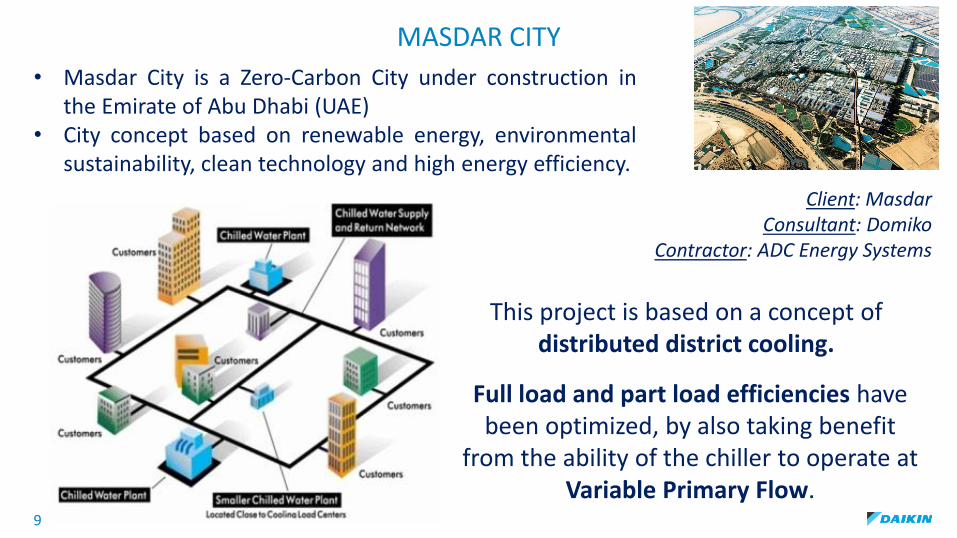
MASDAR CITY
• Masdar City is a Zero-Carbon City under construction inthe Emirate of Abu Dhabi (UAE)
• City concept based on renewable energy, environmentalsustainability, clean technology and high energy efficiency.
Full load and part load efficiencies have been optimized, by also taking benefit
from the ability of the chiller to operate at Variable Primary Flow.
This project is based on a concept of distributed district cooling.
Client: MasdarConsultant: Domiko
Contractor: ADC Energy Systems

10
Project Phase I
2 WCT chillers arranged in series counterflow:
Technical Data at full load:
• Cooling capacity: 6000Tons @ Zero Tolerance• Evaporator water: 60.6F / 44.6F• Condenser water: 93F / 107F
• Efficiency: 0.575kW/TR @ Zero Tolerance
Chillers have been tested at Factory Test Facilityin presence of the Client, at full and part loadswith variable primary flow.
MASDAR CITY

OPERABILITY TESTS
Test conditions
Result% Load
% Evap Water Flow rate
% Cond Water Flow rate
50 50 60 Stable operation for 30 minutes
50 60 60 Stable operation for 30 minutes
50 80 60 Stable operation for 30 minutes11
Test Results
PERFORMANCE TESTS
Test conditions Design Measured Measured Vs Design
% Load% Evap Water
Flow rateCapacity
(TR)Efficiency (kW/TR)
Capacity (TR)
Efficiency (kW/TR)
Capacity kW/TR
100 100 6000 0,575 6127 0,570 + 2,1% - 1,0%
75 75 4500 0,569 4546 0,564 + 0,8% - 0,9%
50 50 3000 0,662 3016 0,628 + 0,0% - 5,1%
30 30 1800 0,646 1966 0,607 + 2,8% - 6,1%
MASDAR CITY

12
MASDAR CITY

13
AL HAMRA VILLAGE (Ras Al Khaimah-UAE)1,500Km of pristine beaches, over 1,000 villas and townhouses, nearly2,500 residential apartments, five hotels, an 18-hole golf course, amarina and a shopping mall.
Project phase IV - 2 parallel WCT chillers/Technical Data:
• Cooling capacity: 2 x 2783Tons @ Zero Tolerance• Evaporator water: 56F / 40F• Condenser water: 94F / 102.5F
• Efficiency: 0.624kW/TR @ Zero Tolerance
PERFORMANCE TESTS (Condenser relief)
Test conditions Design Measured Measured Vs Design
% Load% Evap Water
Flow rateCapacity
(TR)Efficiency (kW/TR)
Capacity (TR)
Efficiency (kW/TR)
Capacity kW/TR
100 100 2783,0 0,624 2847,7 0,618 + 2,3% - 1,0%
75 100 2087,3 0,620 2122,9 0,557 + 1,7% - 10,2%
50 100 1391,5 0,445 1400,8 0,418 + 0,7% - 6,1%
25 100 695,8 0,662 721,4 0,570 + 3,7% - 13,9%
Client: Al Hamra Real Estate DevelopmentConsultant: DC Pro Engineering
Contractor: Turner & Miller International

14
Stadium in Qatar
9 SCF pairs of WCT chillers /Technical Data at full load:
• Cooling capacity: 9 x 5800Tons @ Zero Tolerance• Evaporator water: 57F / 41F• Condenser water: 95F / 109F
• Efficiency: 0.633kW/TR @ Zero Tolerance
PERFORMANCE TESTS (Constant CEWT)
Test conditions Design Measured Measured Vs Design
% Load% Evap Water
Flow rateCapacity
(TR)Efficiency (kW/TR)
Capacity (TR)
Efficiency (kW/TR)
Capacity kW/TR
100 100 5800,0 0,633 5902,3 0,632 + 1,8% 0,0%
75 100 4350,0 0,696 4362,5 0,673 + 0,3% - 3,3%
50 100 2900,0 0,726 2928,2 0,683 + 1,0% - 5,9%
22 100 1276,0 0,636 1295 0,627 + 1,5% - 1,4%

15
New 3000TR
Centrifugal Compressor

New 3000TR Centrifugal Compressor
specifically designed for District Cooling applications
NEW CENTRIFUGAL COMPRESSOR

17
NEW CENTRIFUGAL COMPRESSOR
OVERVIEW
MOTOR
MAIN SUCTION
DISCHARGE
INTERSTAGE PIPING
MOTOR DRIVEN VARIABLE DIFFUSER (DDC)MOTOR DRIVENINLET GUIDE VANES
(IGV)
1° STAGE
2° STAGE
Integral Oil tank with submerged pump to supply lubricating oil
Motor cooling by liquid refrigerant

18
RELIABILITY STABILITYEFFICIENCY
& ENVI. IMPACTSERVICEABILITY
FEATURES & BENEFITS
NEW CENTRIFUGAL COMPRESSOR

19
Compressor
Design features

20
TWO-STAGE ECONOMIZED CYCLE
Standard cycle Economized cycle
• Under high lift conditions the economizer allows higher coolingcapacity (up to + 10%) and efficiency
• Also better reliability and compressor durability thanks to reducedmechanical stress, as the lift is distributed on two impellers.
Flash typeeconomizer
21
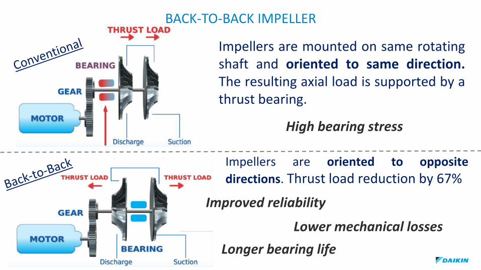
High bearing stress
Impellers are mounted on same rotatingshaft and oriented to same direction.The resulting axial load is supported by athrust bearing.
BACK-TO-BACK IMPELLER
Impellers are oriented to opposite
directions. Thrust load reduction by 67%
Longer bearing life
Lower mechanical losses
Improved reliability
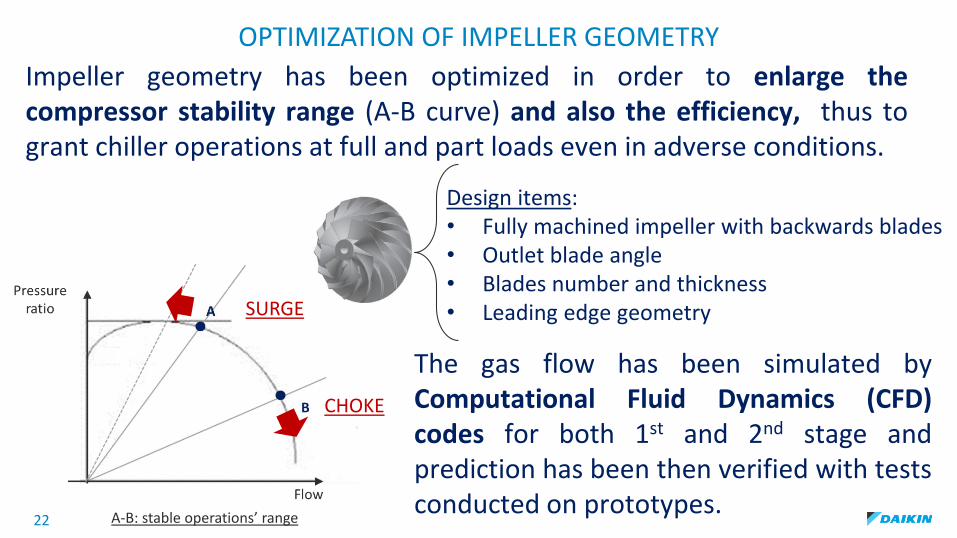
Design items:• Fully machined impeller with backwards blades• Outlet blade angle• Blades number and thickness• Leading edge geometry
22
Impeller geometry has been optimized in order to enlarge thecompressor stability range (A-B curve) and also the efficiency, thus togrant chiller operations at full and part loads even in adverse conditions.
OPTIMIZATION OF IMPELLER GEOMETRY
A-B: stable operations’ range
The gas flow has been simulated byComputational Fluid Dynamics (CFD)codes for both 1st and 2nd stage andprediction has been then verified with testsconducted on prototypes.
SURGE
CHOKE

23
OPTIMIZATION OF IMPELLER GEOMETRY
FULLY MACHINED IMPELLER WITH
BACKWARDS BLADES
The impeller is fully machined - surface has verylow roughness: + 2% advantage in efficiency vsconventional casting.Blades are oriented backwards in order to grantbetter efficiency…
V1: Impeller tip speed V2: Radial velocity of gas R: Resultant velocity
…indeed:• resultant velocity and friction losses are lower. • power needed by the impeller is lower
R

Outlet BLADE angle
24
The larger the impeller outlet blade anglethe lower the min flow at which surgeoccurs.
Such an angle has been increased in order toenlarge the compressor stability range vsconventional impeller.
OUTLET BLADE ANGLEOPTIMIZATION OF IMPELLER GEOMETRY

25
High nr of blades allows load reduction on each blade,therefore blade thickness can be reduced.
Beneficial effects on efficiency and wider stability range.
Compressor design:• Total nr of blades has been increased by the addition of
intermediate splitter blades.• Blade thickness has been reduced.• Length of splitter blades has been increased by inclining
them upstream to better drive the gas flow between full andsplitter blades.
BLADES NUMBER AND THICKNESS
OPTIMIZATION OF IMPELLER GEOMETRY
Full blade
Splitter blade

26
Shape modified from arc to ellipse toimprove flow pattern inside the impeller bysuppressing sudden acceleration anddeceleration at the edge.
LEADING EDGE GEOMETRY
OPTIMIZATION OF IMPELLER GEOMETRY

27
DIFFUSER (VANELESS VS VANED)Kinetic energy at impeller outlet isconverted into pressure energy through thediffuser.
Vaneless diffuser has been selected sinceallows wider operating range and also goodoff-design point efficiency.
Vaneless diffuser helps also to lower soundlevel at diffuser.
Vaneless DiffuserVaned Diffuser
VanelessDiffuser
VanedDiffuser
Flow@Design
Efficiency@Design
Flow
Effi
cien
cy
OperationRange
Design Point Efficiency
Off- Design Point
Efficiency
Vaned Diffuser
Vaneless Diffuser

28
DIFFUSER (DDC = DISCHARGE DIFFUSER CONTROL)
Discharge Diffuser Control avoids surgingand provides 10% efficiency increase at part loads vs hot gas by-pass
Conventional fixed geometry Variable Diffuser

29
INTERSTAGE PIPING (ECONOMIZER)
Piping shape has been designed to avoidany backflow and ensure good mix of hightemperature gas from 1st stage and lowtemperature gas from economizer in orderto prevent any efficiency loss at 2nd stage.

30
RESULTS - EFFICIENCY
Pressure level between 1st and 2nd stage has been set in order to enhance the economized cycle and overall chiller performance

31
COMPRESSOR DESIGN - CONCLUSIONS
THE GOAL HAS BEEN ACHIEVED!
MAX STABILITY VS SURGE/CHOKE:SAFE OPERATIONS ALSO WITH
HIGHER CEWT VS DESIGN
OPTIMIZED OVERALL EFFICIENCY-0.63KW/TR @ ME CONDITIONS

32
From Compressor to Chiller
WCT-series, optimized for District Cooling applications
3000TR Cooling Capacity @ Middle East DC conditions
0.63kW/TR Zero Tolerance
56/40F95/105F
WCT - Chilleroverview

33
Future-ready (new refrigerants)
MOP 28 – Kigali amendment
HFC Phase-down schedule for Bahrain, India, Iran, Iraq, Kuwait, Oman, Pakistan, Qatar, Saudi Arabia and UAE
2028 to 2031: 100%
(base line)
2032 to 2036: 90%2037 to 2041: 80%2042 to 2046: 70%2047 and therefore: 15%
No Phase Out planned for HFCs,incl. R134a. The process requires agradual reduction of HFCs’consumption.
Daikin/Daikin Chemicals is also aproducer of refrigerants and isworking to provide: Retrofit package for R-134a WCT
units already installed WCT new series, fitted with low
GWP refrigerant.
WCT series - R134a -
Tons of CO2
equiv.

THANK YOU
34