Embed Size (px)
Citation preview
Introduction
Foam manufacturing processes for resins started
with the production of polystyrene foam and polyethyl-
ene foam at Dow Chemical Company in 1959, and after
that, various technologies for foam manufacturing
processes and products were developed ranging from
thermoplastic resins to thermosetting resins.
Giving an overview of the plastic foaming products
market, a variety of resin processing products having
functions such as light weight, flexibility (cushioning
properties), insulating properties and sound absorbing
properties which make use of the characteristics of the
amount of expansion and cell diameter and shape
derived from the properties of the resin and the foam-
ing processes are being used in food-packaging materi-
als, distribution packaging materials, automotive parts,
construction materials, etc. The scale of the market
was approximately 630 billion yen in 2005.
While Sumitomo Chemical supplies the market with
polyethylene, polypropylene and polystyrene as the
raw material resins for plastic foaming products, Sumi-
celler®, which is a polypropylene extrusion foam sheet,
was brought to the market in 1990 through a combina-
tion of Sumitomo Chemical’s own materials design
technology and foaming process technology. In 1997,
operations for it moved to Sumika Plastech Co., Ltd.
Since Sumiceller® went on the market, the authors
have progressed with investigations for improving
quality, developed high additive value products and,
further, developed new applications. At the same time,
we have accumulated a large amount of diversified and
integrated elemental technology (catalyst and material
design, polymerization processes, devices for molding
processes, molding process methods, etc.) related to
polypropylene extrusion foaming. In particular, new
molding process technology that has made advance-
ments and integrated reduced pressure molding
process technologies like vacuum molding processes
increase the additive value of Sumiceller® as well as
opening the door to the development of new applica-
tions for polypropylene extrusion foam sheets. It has
been the driving force behind the development of high-
ly value added automotive parts with weight reduction,
higher rigidity and higher heat resistance.
In this paper, we will give an overview of the charac-
1SUMITOMO KAGAKU 2008-I
Development of NovelPolypropylene Foaming/MoldingTechnologies and Products forSumiceller®
Sumitomo Chemical Co., Ltd.
Plastics Technical Center
Jinsho NAMBU
Tomoo HIROTA
Akira UOTANI
Sumika Plastech Co., Ltd.
Yoshinori OOMURA
Sumika Plastech Tochigi Co., Ltd.
Akinobu SAKAMOTO
Plastic foaming products (polystyrene, polyethylene and polypropylene) are used in various fields in itemssuch as food-packaging materials, distribution packaging materials, automotive parts and construction materials.
Each product has its own characteristics such as light weight, flexibility (cushioning properties), heat insu-lation properties and sound absorption properties, which depend on factors such as the resin properties andfoaming processes in each application field.
In automotive parts applications in particular, polypropylene foaming technologies and products arebecoming the center of attention from the points of view of weight reduction and recyclability.
In this paper, we review the novel polypropylene foaming/molding technologies and products for Sumi-celler®, and give our consideration to the requirement of weight reduction for automotive parts.
This paper is translated from R&D Report, “SUMITOMO KAGAKU”, vol. 2008-I.
teristics of Sumiceller® polypropylene extrusion foam
sheets, which were developed through a combination
of our own materials technology and molding process
technology as well as introduce our work on the devel-
opment of new process products using new molding
process technology. Furthermore, we would like to
touch upon our thinking about the development of
foaming/molding technologies and products for the
requirement for weight reduction in automotive parts.
Foaming Technology
1. Classification of technology
Essentially, plastic foaming is generating gas in the
resin material and forming an expanded body (foam)
where these voids (bubbles) are hardened with a tar-
geted shape and size. Here, we classify plastic foaming
technologies according to the source generating the
foaming gas and the state of the resin material during
the foaming process (Table 1).
The technology is classified according to the method
for generating the gas in the foaming process and the
substance generated as “chemical foaming methods,”
where the gas is generated by a chemical reaction, and
the broader sense of “physical foaming methods,”
where the volatile substance is dissolved in the resin
material and the gas formed.
The compounds used in chemical foaming methods
include organic foaming agents such as azodicar-
bonamide (ADCA) and inorganic foaming agents such
as sodium bicarbonate. In addition, Freon gas, hydro-
carbon based organic solvents, carbon dioxide and
nitrogen may be cited as foaming agents used in physi-
cal foaming methods in the order of the era in which
the technology was developed. Since Freon gas and
hydrocarbon based organic solvents typically have a
high latent heat when volatilizing (vaporizing and evap-
orating), they effectively lower the temperature of the
resin, which is in a molten plastic state and rapidly
solidify the void (bubble) walls, so they have the char-
acteristic of making it possible to stably obtain prod-
ucts with high expansion ratios of 30×.
On the other hand, carbon dioxide and nitrogen have
the characteristics of (i) not being toxic, (ii) reaching a
critical state at a comparatively low temperature (criti-
cal temperature of carbon dioxide being 31.0°C with a
critical pressure of 72.9atm and the critical temperature
of nitrogen being –147°C with a critical pressure of
33.5atm), and (iii) having a comparatively high solubili-
ty in resin materials, so investigations into them as
“volatile substances” that are friendly to the Earth’s
environment have been actively pursued in recent
years. Moreover, carbon dioxide is mainly used in
extrusion foaming process, while nitrogen is mainly
used in injection foaming process. In addition, since it
is known that the glass transition temperature of poly-
mers is lowered because carbon dioxide is dissolved,
use of carbon dioxide in extrusion foaming process can
be thought of as being not only a source of gas genera-
tion, but also a method that modifies the foaming
process properties accompanied by a reduction in the
viscosity of the system.1), 2)
In the background of these changes in volatile sub-
stances, are an increase in new societal needs that are
aimed at sustainable global growth and development
that takes into consideration the Earth’s environment
of which the Montreal Protocol (related to substances
that damage the ozone layer, issued in 1989), the
revised Air Pollution Control Law (regulating volatile
organic compounds, revised in 2004) and the Kyoto
Protocol (concerning the reductions in greenhouse
gases which are a cause of global warning, issued in
2005) are representative.
In addition, we can make classifications according to
the state of the material during foaming into “molten
foaming methods,” where foaming takes place in a
molten state, “solid foaming methods,” where there is
foaming in a solid-state and, further, “cast foaming
methods,” where a liquid material is foamed during
cast molding. In addition, molten foaming molding can
be roughly divided into “cross-linking foaming meth-
ods,” such as “chemical cross-linking” and “electron
beam cross-linking,” and “non-cross-linked foaming
methods” such as extrusion foaming. Moreover, Sumi-
2SUMITOMO KAGAKU 2008-I
Development of Novel Polypropylene Foaming/Molding Technologies and Products for Sumiceller®
Table 1 Classification of expansion processing thechnologies
Physical
Expansion agent
Chemical
CFC
Hydrocarbon
CO2/N2
—
Polymerization foaming
(Polyurethene)—
—
riquidState of material under foaming process
Injection/Extrusion foaming
Extrusion foaming
Injection/Extrusion foaming
melted
—
Beads foaming
—
solid
celler®, which is introduced in this paper, is classified
as a non-cross-linked extrusion foaming method.
2. Polypropylene foaming
Polypropylene is a general-purpose resin that is
widely used as a low-cost and environmentally friendly
resin with excellent heat resistance, chemical resis-
tance, light weight and recyclability, and it has uses in
a wide variety of fields of application and a high growth
rate. In addition, polypropylene foaming products
include (i) low expansion products (within an expan-
sion ratio of 5× or less, non-cross-linked, continuous
processes), (ii) high expansion products (expansion
ratios greater than 5×) and (iii) bead expansion prod-
ucts (expansion ratios of 15× to 45×, non-cross-linked,
batch process). Since the recyclability and productivity
for foaming products using non-cross-linked, continu-
ous processes such as Sumiceller® is superior, we can
expect growth in the future.
However, since polypropylene is a crystalline resin,
sudden changes in the viscosity arise around the melt-
ing point, and since the gas that is generated cannot be
solidified effectively as voids (bubbles), it has inferior
expansion molding properties in terms of expansion
ratio and independent bubble ratio. It is thought that it
would be effective to improve the melt strength and
increase the gas holding ability to make improvements
in these, so there have been proposals for material that
focus on strain hardening properties during extension-
al flow. Specifically, there have been proposals for
methods such as (i) widening the molecular weight dis-
tribution, (ii) producing long chain branches, for exam-
ple, by electron beam irradiation treatment and (iii)
creating composites with other resins (materials with
ultrahigh molecular weights) having a high molten ten-
sile strength.3)–6)
There is a long history of investigations into control-
ling molecular weight distribution using polymer
blends and multistage polymerization, and there is a
wealth of actual results in improvements (drawdown
control) to the vacuum molding properties of
polypropylene sheets.
In recent years, a new high melt strength polypropy-
lene known as New-foamer® (reactor made HMSPP)
from Japan Polypropylene Corp. has appeared on the
market. In addition to the characteristics of a high melt
strength and high strain hardening properties in exten-
sion deformation, New-foamer® is superior to conven-
tional HMSPP in terms of having less reduction in
MFR during recycling (repeated kneading).7)
In addition to moving forward with environmental
responsiveness such as reduction in energy and reduc-
tion in resources maximizing the characteristics of
polypropylene materials, it is necessary to develop low-
cost catalysts and polymerization processes and devel-
op materials with superior foaming processability and
fitness for recycling. To do this, it is important to exam-
ine the improvements in the foaming processability for
polypropylene materials focusing on melt strength and
strain hardening properties.
3. Sumiceller® polypropylene extrusion foam
sheet
Sumiceller® is a polypropylene material developed
through Sumitomo Chemical’s own catalyst material
design and polymerization process and is a polypropy-
lene extruded foam sheet developed by combining this
with our own expansion molding technology.
Besides a 1.3× expansion foaming product that is
mainly used for protective materials in floor and wall
surfaces and a 3.0× expansion foaming product that is
used in boxes, partition, cushioning material, etc.,
there are functional materials, such as functional films
and nonwoven cloth, and special laminated grades of
Sumiceller®. It is also used in a wide variety of fields
such as distribution packaging materials, signboards,
display materials and automotive parts. The authors
have concentrated their energy on the technical devel-
opment of lamination and integration with different
types of materials, which are considered as important
elemental technologies for new application fields with
the objective of providing surface improvements and
better design characteristics.
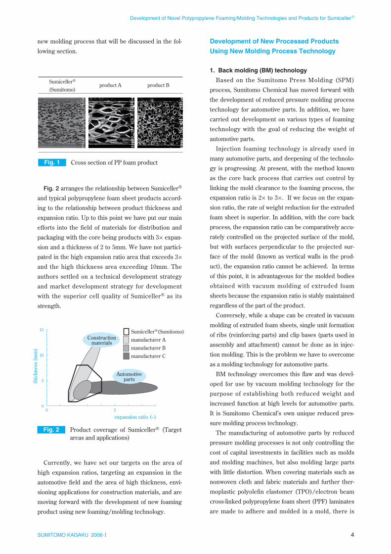
Fig. 1 is a cross-sectional photograph of Sumiceller®
and typical polypropylene foam sheet products in the
market. Moreover, the specifications for each of the
products are constant with an expansion ratio of 3×and a thickness of 3.0mm, but there is a definitive dif-
ference in the size of the cells (cell wall thickness).
If we calculate the number of cells per unit cross-
sectional area for reference, we can see that the num-
ber of cells in the Sumiceller® is 10 to 100 times larger
than that of others. This difference in cell diameter
can be thought of as arising because of the melt prop-
erties of the resins used and the foaming process
(foaming agent and device), therefore the uniform and
fine cells of Sumiceller® have a great advantage not
only for the quality of the foam sheet, but also in the
3SUMITOMO KAGAKU 2008-I
Development of Novel Polypropylene Foaming/Molding Technologies and Products for Sumiceller®
new molding process that will be discussed in the fol-
lowing section.
Fig. 2 arranges the relationship between Sumiceller®
and typical polypropylene foam sheet products accord-
ing to the relationship between product thickness and
expansion ratio. Up to this point we have put our main
efforts into the field of materials for distribution and
packaging with the core being products with 3× expan-
sion and a thickness of 2 to 5mm. We have not partici-
pated in the high expansion ratio area that exceeds 3×and the high thickness area exceeding 10mm. The
authors settled on a technical development strategy
and market development strategy for development
with the superior cell quality of Sumiceller® as its
strength.
Currently, we have set our targets on the area of
high expansion ratios, targeting an expansion in the
automotive field and the area of high thickness, envi-
sioning applications for construction materials, and are
moving forward with the development of new foaming
product using new foaming/molding technology.
Development of New Processed Products
Using New Molding Process Technology
1. Back molding (BM) technology
Based on the Sumitomo Press Molding (SPM)
process, Sumitomo Chemical has moved forward with
the development of reduced pressure molding process
technology for automotive parts. In addition, we have
carried out development on various types of foaming
technology with the goal of reducing the weight of
automotive parts.
Injection foaming technology is already used in
many automotive parts, and deepening of the technolo-
gy is progressing. At present, with the method known
as the core back process that carries out control by
linking the mold clearance to the foaming process, the
expansion ratio is 2× to 3×. If we focus on the expan-
sion ratio, the rate of weight reduction for the extruded
foam sheet is superior. In addition, with the core back
process, the expansion ratio can be comparatively accu-
rately controlled on the projected surface of the mold,
but with surfaces perpendicular to the projected sur-
face of the mold (known as vertical walls in the prod-
uct), the expansion ratio cannot be achieved. In terms
of this point, it is advantageous for the molded bodies
obtained with vacuum molding of extruded foam
sheets because the expansion ratio is stably maintained
regardless of the part of the product.
Conversely, while a shape can be created in vacuum
molding of extruded foam sheets, single unit formation
of ribs (reinforcing parts) and clip bases (parts used in
assembly and attachment) cannot be done as in injec-
tion molding. This is the problem we have to overcome
as a molding technology for automotive parts.
BM technology overcomes this flaw and was devel-
oped for use by vacuum molding technology for the
purpose of establishing both reduced weight and
increased function at high levels for automotive parts.
It is Sumitomo Chemical’s own unique reduced pres-
sure molding process technology.
The manufacturing of automotive parts by reduced
pressure molding processes is not only controlling the
cost of capital investments in facilities such as molds
and molding machines, but also molding large parts
with little distortion. When covering materials such as
nonwoven cloth and fabric materials and further ther-
moplastic polyolefin elastomer (TPO)/electron beam
cross-linked polypropylene foam sheet (PPF) laminates
are made to adhere and molded in a mold, there is
4SUMITOMO KAGAKU 2008-I
Development of Novel Polypropylene Foaming/Molding Technologies and Products for Sumiceller®
Fig. 1 Cross section of PP foam product
Sumiceller® (Sumitomo)
product Bproduct A
Fig. 2 Product coverage of Sumiceller® (Target areas and applications)
0
5
10
15
0 5
thic
knes
s (m
m)
expansion ratio (–)
Automotiveparts
Constructionmaterials
Sumiceller®(Sumitomo)
manufacturer A
manufacturer B
manufacturer C
merit to controlling the damage (breakdown of the
nonwoven cloth fabric, to the covering material and
puncturing of the PPF) and increasing the designabili-
ty. In particular, the parts around the inner panels of
doors for which there are many opportunities for being
looked at by passengers among the interior parts of
automobiles have a high standard of requirements for
appearance.
As a result of the authors making progress in deep-
ening and advancing molding process technology to
respond to these requirements, BM technology that
integrates and combines vacuum molding and extru-
sion molding into a series of processes has been
brought to fruition.8)
Fig. 3 shows the flow of the BM process. First of all,
Sumiceller® that has been softened by heating to a pre-
scribed temperature in a heating process is sand-
wiched in a core and cavity mold pair and partial mold-
ing is carried out by applying a vacuum. (In this dia-
gram, the case of vacuum forming pulled towards the
core mold is shown, and the vacuum is applied from
the cavity surface, which is the design surface. In addi-
tion, the core mold is used as a plug-assist supporting
the application of the vacuum.) Next, plasticized resin
is supplied from the side opposite to the design surface
(core mold) to the Sumiceller® that has been partially
molded by vacuum forming, and ribs, clip seats and
other functional parts are molded as a unit.
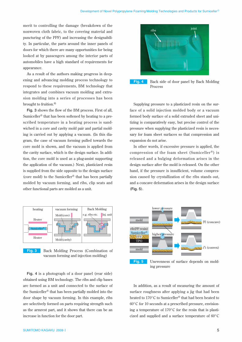
Fig. 4 is a photograph of a door panel (rear side)
obtained using BM technology. The ribs and clip bases
are formed as a unit and connected to the surface of
the Sumiceller® that has been partially molded into the
door shape by vacuum forming. In this example, ribs
are selectively formed on parts requiring strength such
as the armrest part, and it shows that there can be an
increase in function for the door part.
Supplying pressure to a plasticized resin on the sur-
face of a solid injection molded body or a vacuum
formed body surface of a solid extruded sheet and uni-
tizing is comparatively easy, but precise control of the
pressure when supplying the plasticized resin is neces-
sary for foam sheet surfaces so that compression and
expansion do not arise.
In other words, if excessive pressure is applied, the
compression of the foam sheet (Sumiceller®) is
released and a bulging deformation arises in the
design surface after the mold is released. On the other
hand, if the pressure is insufficient, volume compres-
sion caused by crystallization of the ribs stands out,
and a concave deformation arises in the design surface
(Fig. 5).
In addition, as a result of measuring the amount of
surface roughness after applying a jig that had been
heated to 170°C to Sumiceller® that had been heated to
60°C for 10 seconds at a prescribed pressure, envision-
ing a temperature of 170°C for the resin that is plasti-
cized and supplied and a surface temperature of 60°C
5SUMITOMO KAGAKU 2008-I
Development of Novel Polypropylene Foaming/Molding Technologies and Products for Sumiceller®
Fig. 5 Unevenness of surface depends on mold-ing pressure
mold
rib(PP resin)Sumiceller®
PPFPPFPPFTPO
mold
lower pressure
higher pressure
Fig. 3 Back Molding Process (Combination of vacuum forming and injection molding)
vacuum forming Back Molding
e.g. ribs etc.Mold(core)
heating
Mold(cavity)
Heater
Heater
Inj. unit
Sumiceller®
Fig. 4 Back side of door panel by Back Molding Process
ribs joint
for the Sumiceller®, to obtain guidelines for pressure
control during the molding process, it was confirmed
that the bulging deformations where less than 0.5mm if
the pressure was 3MPa or less and that it could be con-
trolled to a minute deformation of an extent that was
not visually discernible (Fig. 6).
When molding is done with multiple channels of dif-
ferent channel lengths through a single point gate, it is
known that bulging deformations caused by pressure
excesses at the short channels and concave deforma-
tions and the long channels arise. Therefore, not letting
the channels be too long and making them uniform
reduces the damage to the Sumiceller®, and can also
be thought of as being effective in stabilizing the con-
tact between parts. In addition, by controlling the sup-
ply pressure for the plasticized resin in a stepwise mat-
ter, it is possible to obtain high quality molded parts
without losing the appearance of the design surface or
the strength of the product.
Furthermore, it is possible to apply typical injection
molding technology such as multi-point gate and valve
gate (individual control of opening and closing timing
possible), and in addition by applying a vacuum from
the cavity mold side, it is possible to use vacuum/blow
molding that combines this with air pressure blown
from the core mold side.
BM technology of this sort forms a linked group of
techniques from the elemental technologies forming
the core and optional peripheral technologies for solv-
ing problems. Sumitomo Chemical provides licenses to
molding process makers through Sumika Plastech Co.,
Ltd., along with promoting the dissemination of the
technology, and continuing to think in terms of putting
effort into brushing up the technology so as to increase
the attractiveness of Sumiceller® sales promotion
cards.
2. Form expansive molding (FEM) technology
Sumitomo chemical developed polypropylene
extruded foam sheets for food product packaging con-
tainers targeting the trays that are used for packaging
meat, fish and side dishes in supermarkets and conve-
nience stores and the bowls for instant noodles. In
addition, with the goal of making increased additive
value in foam sheets, we carried out parallel investiga-
tions into the vacuum molding processes for various
types of containers.
The important points when vacuum molding foam
sheets are maintaining a uniform product thickness
and independent bubble ratio. Typically, in deep draw-
ing (high draw ratio) molding such as that for bowls,
the problems are that localized thick parts arise and
there is a drop in the independent bubble ratio. To
counteract this, we developed technology for control-
ling the thinning out of the strong parts that are pulled
down strongly, by using a core and cavity mold pair
and by applying a vacuum from both sides of the mold.
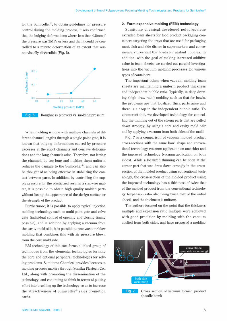
Fig. 7 is a comparison of vacuum molded product
cross-sections with the same bowl shape and conven-
tional technology (vacuum application on one side) and
the improved technology (vacuum application on both
sides). While a localized thinning can be seen at the
corner part that was draw down strongly in the cross-
section of the molded product using conventional tech-
nology, the cross-section of the molded product using
the improved technology has a thickness of twice that
of the molded product from the conventional technolo-
gy (expansion ratio also being twice that of the initial
sheet), and the thickness is uniform.
The authors focused on the point that the thickness
multiple and expansion ratio multiple were achieved
with good precision by molding with the vacuum
applied from both sides, and have proposed a molding
6SUMITOMO KAGAKU 2008-I
Development of Novel Polypropylene Foaming/Molding Technologies and Products for Sumiceller®
Fig. 6 Roughness (convex) vs. molding pressure
0.0
0.1
0.2
0.0 1.0 2.0 3.0 4.0 5.0
molding pressure (MPa)
roug
hnes
s (m
m)
Fig. 7 Cross section of vacuum formed product (noodle bowl)
A
B C
A
B C
both sidevacuuming
conventional(one side vacuuming)
As was explained in Fig. 1, Sumiceller® has the char-
acteristic of the diameter of the expansion cells being
extremely fine and uniform. The quality of these cells
is also an important characteristic in FEM technology,
and deformation (expansion in the direction of thick-
ness) of the cells during FEM can be thought of as
being easy. In addition, with Sumiceller®, the presence
of an optimally designed skin layer can be thought of
as effectively controlling the selective expansion and
deformation in the direction of thickness.
The molding method that efficiently gives products
with a high foaming ratio and thickness is technology
that can provide solutions for both of the problems of
decreasing weight and increasing rigidity in automo-
tive parts. Here we would like to consider the rigidity
of FEM molded products using Sumiceller® in a model
of a 2.3mm thick solid molded product made of a
polypropylene block copolymer, envisioned for typical
interior parts for automobile.
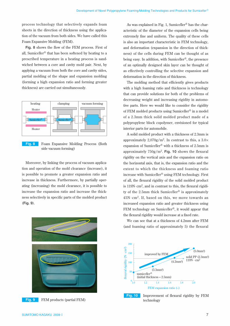
A solid molded product with a thickness of 2.3mm is
approximately 2,070g/m2. In contrast to this, a 3.0×expansion of Sumiceller® with a thickness of 2.5mm is
approximately 750g/m2. Fig. 10 shows the flexural
rigidity on the vertical axis and the expansion ratio on
the horizontal axis, that is, the expansion ratio and the
extent to which the thickness and foaming ratio
increase with Sumiceller® using FEM technology. First
of all, the flexural rigidity of the solid molded product
is 119N ·cm2, and in contrast to this, the flexural rigidi-
ty of the 2.5mm thick Sumiceller® is approximately
45N · cm2. If, based on this, we move towards an
increased expansion ratio and greater thickness using
FEM technology on Sumiceller®, it would appear that
the flexural rigidity would increase at a fixed rate.
We can see that at a thickness of 4.2mm after FEM
(and foaming ratio of approximately 5) the flexural
process technology that selectively expands foam
sheets in the direction of thickness using the applica-
tion of the vacuum from both sides. We have called this
Foam Expansive Molding (FEM).
Fig. 8 shows the flow of the FEM process. First of
all, Sumiceller® that has been softened by heating to a
prescribed temperature in a heating process is sand-
wiched between a core and cavity mold pair. Next, by
applying a vacuum from both the core and cavity sides,
partial molding of the shape and expansion molding
(forming a high expansion ratio and forming greater
thickness) are carried out simultaneously.
Moreover, by linking the process of vacuum applica-
tion and operation of the mold clearance (increase), it
is possible to promote a greater expansion ratio and
increase in thickness. Furthermore, by partially oper-
ating (increasing) the mold clearance, it is possible to
increase the expansion ratio and increase the thick-
ness selectively in specific parts of the molded product
(Fig. 9).
7SUMITOMO KAGAKU 2008-I
Development of Novel Polypropylene Foaming/Molding Technologies and Products for Sumiceller®
Fig. 8 Foam Expansive Molding Process (Both side vacuum forming)
Heater
Heater
Sumiceller® Sumiceller®
vacuum formingclampingheating
Fig. 9 FEM products (partial FEM)Fig. 10 Improvement of flexural rigidity by FEM
technology
0
50
100
150
200
1.0 1.2 1.4 1.6 1.8 2.0
flexy
ral r
igid
ity (
N ·
cm2 )
solid PP (2.3mmt)119N · cm2
sumiceller® (initial thickness = 2.5mm)
(3.3mmt)
(4.2mmt)
(5.0mmt)improved by FEM
FEM expansion ratio (–)
technology that continuously manufacturers high foam-
ing ratio, high thickness Sumiceller®. As an investiga-
tion of industrialization for this process, we examined
expansion forming in the direction of thickness using a
small vacuum chamber and keeping the planar shape
of the Sumiceller® the same in a batch system.
To confirm whether it was possible to control foam-
ing ratio and the thickness of the final product using
the vacuum chamber clearance in this process, we
inquired into the changes in the atmospheric pressure
and internal pressure in the bubbles in the various
processes. The preconditions for the inquiry are given
in Table 2.
The atmosphere for the heating process was at
atmospheric pressure, and as the temperature
increased the internal cell pressure was 0.1MPa + ∆P.
The cell walls increased up to heating temperature.
When the sheet in this condition was placed in the vac-
uum chamber and placed under a vacuum, adiabatic
expansion occurred because of the difference between
the pressure in the atmosphere and the pressure inside
the cells, and it expanded to the extent of the clearance
in the vacuum chamber. Furthermore, it was cooled to
room temperature while maintaining the vacuum state,
and the foaming ratio and thickness were fixed. More-
over, with the reduction in pressure and cooling, the
internal pressure in the cells was reduced and became
0.1MPa – ∆P. If the sheet is removed and placed under
atmospheric pressure after cooling is completed, there
is a possibility that it will shrink because of the differ-
ence in pressure with the internal pressure of the cells,
which were in a reduced pressure state.
To clarify this point, we carried out a simulation of
how the sheet changed because of this difference in
pressure while referring to resource9) in the Refer-
ences list. An overview of the simulation is shown in
Fig. 11.
Presupposing a sheet model with a thickness L
where bubbles of the same shape are arranged in one
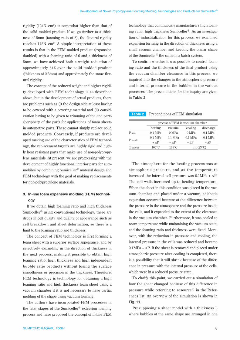
rigidity (124N ·cm2) is somewhat higher than that of
the solid molded product. If we go further to a thick-
ness of 5mm (foaming ratio of 6), the flexural rigidity
reaches 175N ·cm2. A simple interpretation of these
results is that in the FEM molded product (expansion
doubled) with a foaming ratio of 6 and a thickness of
5mm, we have achieved both a weight reduction of
approximately 64% over the solid molded product
(thickness of 2.3mm) and approximately the same flex-
ural rigidity.
The concept of the reduced weight and higher rigidi-
ty developed with FEM technology is as described
above, but in the development of actual products, there
are problems such as (i) the design side at least having
to be covered with a covering material and (ii) consid-
eration having to be given to trimming of the end parts
(periphery of the part) for applications of foam sheets
in automotive parts. These cannot simply replace solid
molded products. Conversely, if products are devel-
oped making use of the characteristics of FEM technol-
ogy, the replacement targets are highly rigid and high-
ly heat resistant parts that make use of non-polypropy-
lene materials. At present, we are progressing with the
development of highly functional interior parts for auto-
mobiles by combining Sumiceller® material design and
FEM technology with the goal of making replacements
for non-polypropylene materials.
3. In-line foam expansive molding (FEM) technol-
ogy
If we obtain high foaming ratio and high thickness
Sumiceller® using conventional technology, there are
drops in cell quality and quality of appearance such as
cell breakdown and sheet deformation, so there is a
limit to the foaming ratio and thickness.
The concept of FEM technology is first forming a
foam sheet with a superior surface appearance, and by
selectively expanding in the direction of thickness in
the next process, making it possible to obtain high
foaming ratio, high thickness and high independent
bubble ratio products without losing the surface
smoothness or precision in the thickness. Therefore,
FEM technology is technology for obtaining a high
foaming ratio and high thickness foam sheet using a
vacuum chamber if it is not necessary to have partial
molding of the shape using vacuum forming.
The authors have incorporated FEM processes in
the later stages of the Sumiceller® extrusion foaming
process and have proposed the concept of in-line FEM
8SUMITOMO KAGAKU 2008-I
Development of Novel Polypropylene Foaming/Molding Technologies and Products for Sumiceller®
Table 2 Preconditions of FEM simulation
P atm.
P in cell
T cellwall
0.1 MPa0.1 MPa
+ ∆P165°C
heating0 MPa
0.1 MPa– ∆P165°C
vacuum
process of FEM in vacuum chamber
0 MPa0.1 MPa
– ∆Pr.t.(23°C)
cooling0.1 MPa0.1 MPa
– ∆P
discharge
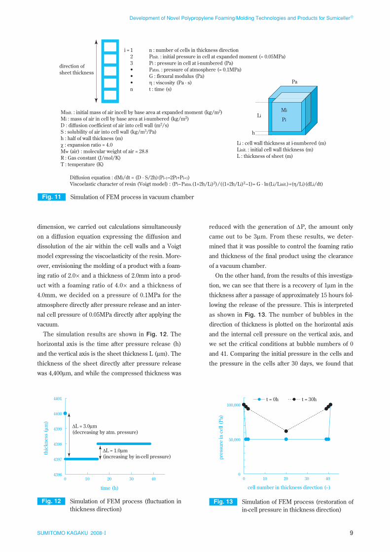
dimension, we carried out calculations simultaneously
on a diffusion equation expressing the diffusion and
dissolution of the air within the cell walls and a Voigt
model expressing the viscoelasticity of the resin. More-
over, envisioning the molding of a product with a foam-
ing ratio of 2.0× and a thickness of 2.0mm into a prod-
uct with a foaming ratio of 4.0× and a thickness of
4.0mm, we decided on a pressure of 0.1MPa for the
atmosphere directly after pressure release and an inter-
nal cell pressure of 0.05MPa directly after applying the
vacuum.
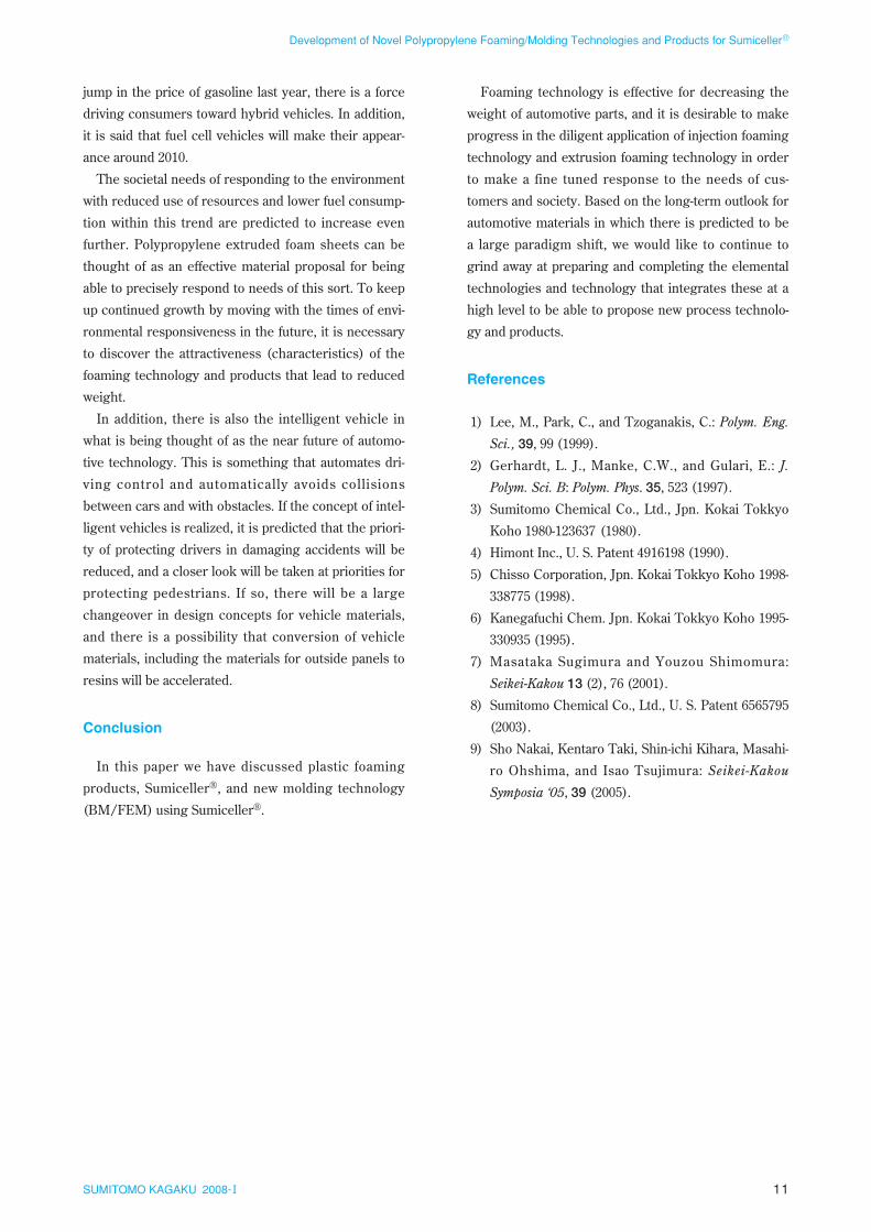
The simulation results are shown in Fig. 12. The
horizontal axis is the time after pressure release (h)
and the vertical axis is the sheet thickness L (µm). The
thickness of the sheet directly after pressure release
was 4,400µm, and while the compressed thickness was
reduced with the generation of ∆P, the amount only
came out to be 3µm. From these results, we deter-
mined that it was possible to control the foaming ratio
and thickness of the final product using the clearance
of a vacuum chamber.
On the other hand, from the results of this investiga-
tion, we can see that there is a recovery of 1µm in the
thickness after a passage of approximately 15 hours fol-
lowing the release of the pressure. This is interpreted
as shown in Fig. 13. The number of bubbles in the
direction of thickness is plotted on the horizontal axis
and the internal cell pressure on the vertical axis, and
we set the critical conditions at bubble numbers of 0
and 41. Comparing the initial pressure in the cells and
the pressure in the cells after 30 days, we found that
9SUMITOMO KAGAKU 2008-I
Development of Novel Polypropylene Foaming/Molding Technologies and Products for Sumiceller®
Fig. 12 Simulation of FEM process (fluctuation in thickness direction)
4396
4397
4398
4399
4400
4401
0 10 20 30 40
thic
knes
s (µ
m)
time (h)
∆L = 3.0µm(decreasing by atm. pressure)
∆L = 1.0µm(increasing by in-cell pressure)
Fig. 13 Simulation of FEM process (restoration of in-cell pressure in thickness direction)
0
50,000
100,000
0 10 20 30 40
t = 0h t = 30h
pres
sure
in c
ell (
Pa)
cell number in thickness direction (–)
Fig. 11 Simulation of FEM process in vacuum chamber
n : number of cells in thickness directionPinit. : initial pressure in cell at expanded moment (= 0.05MPa)Pi : pressure in cell at i-numbered (Pa)Patm. : pressure of atmosphere (= 0.1MPa)G : flexural modulus (Pa)η : viscosity (Pa · s)t : time (s)
Minit. : initial mass of air incell by base area at expanded moment (kg/m2)Mi : mass of air in cell by base area at i-numbered (kg/m2)D : diffusion coefficient of air into cell wall (m2/s)S : solubility of air into cell wall (kg/m3/Pa)h : half of wall thickness (m)χ : expansion ratio = 4.0Mw (air) : molecular weight of air = 28.8R : Gas constant (J/mol/K)T : temperature (K)
Diffusion equation : dMi/dt = (D · S/2h)(Pi-1–2Pi+Pi+1)Viscoelastic character of resin (Voigt model) : (Pi–Patm.(1+2h/Li)2)/((1+2h/Li)2–1)= G · ln(Li/Linit.)+(η/Li)(dLi/dt)
direction ofsheet thickness
i = 123•••n
Li : cell wall thickness at i-numbered (m)Linit. : initial cell wall thickness (m)L : thickness of sheet (m)
Li
h
Pi
Pa
Mi
mitigation of the pressure in the cells to the atmos-
phere required an extremely long time. We interpret
this to mean that the thickness recovery above is a phe-
nomenon that accompanies the mitigation of the pres-
sure in the cells to the atmosphere. Moreover, it was
found that the mitigation of the pressure in the cells in
the center of the sheet required a longer time than that
at the periphery.
Going forward, we want to move forward with device
design and prototypical examinations of large products
to increase the scale while moving forward with exami-
nations into the optimization of the heating conditions
and pressure control conditions for maintaining of the
independent bubble ratio and improving the surface
smoothness.
Vision for the Future of Automotive Parts
1. Reduction of weight in automotive parts
The goal of reducing the weight of automobiles
(parts) is improving specific fuel consumption (fuel
economy: km/liter) and reducing the amount of carbon
dioxide emissions. Moreover, a 22.8% improvement by
FY 2010 has been set as a goal for the improvement of
fuel economy. This means an approximately
3.4km/liter improvement for a passenger car with a
fuel economy of 15km/liter and an increased driving
distance of 200km if we think in terms of a 60 L full
tank of gasoline.
Naturally, automotive makers are proposing a step-
wise and continuous weight reduction of 5 to 10% in
new vehicle development for this goal, and not only
materials and parts, but also vehicle designs them-
selves are being reassessed.
In addition, while this severe weight reduction goal
has been set, development aimed at supplying safer
automobiles with comfortable spaces is moving for-
ward and is following a one-way road toward increases
in the average vehicle weight of passenger cars. In
other words, our untiring attempts at reducing the
weight of automotive parts are an attempt to conform
to environmental regulations while increasing the safe-
ty of automobiles and level of satisfaction with comfort.
Moreover, we digress, but while vehicle weight (net
weight of the empty vehicle) is a basic indicator, the
setting of the target standards for fuel economy is a set-
ting based on equivalent inertial weight (weight viewed
for each category divided into classes for test vehicle
weight with the weight of two passengers, 110kg,
added), so there are cases where even if a vehicle is
classified into one lower equivalent inertial weight cate-
gory by only becoming 1kg lighter in vehicle weight, it
is seen as achieving a weight reduction of 250kg.
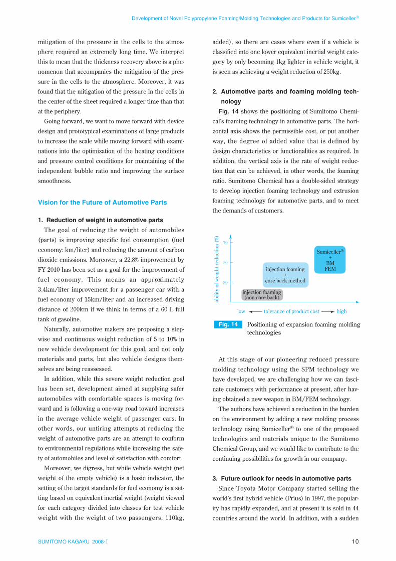
2. Automotive parts and foaming molding tech-
nology
Fig. 14 shows the positioning of Sumitomo Chemi-
cal’s foaming technology in automotive parts. The hori-
zontal axis shows the permissible cost, or put another
way, the degree of added value that is defined by
design characteristics or functionalities as required. In
addition, the vertical axis is the rate of weight reduc-
tion that can be achieved, in other words, the foaming
ratio. Sumitomo Chemical has a double-sided strategy
to develop injection foaming technology and extrusion
foaming technology for automotive parts, and to meet
the demands of customers.
At this stage of our pioneering reduced pressure
molding technology using the SPM technology we
have developed, we are challenging how we can fasci-
nate customers with performance at present, after hav-
ing obtained a new weapon in BM/FEM technology.
The authors have achieved a reduction in the burden
on the environment by adding a new molding process
technology using Sumiceller® to one of the proposed
technologies and materials unique to the Sumitomo
Chemical Group, and we would like to contribute to the
continuing possibilities for growth in our company.
3. Future outlook for needs in automotive parts
Since Toyota Motor Company started selling the
world’s first hybrid vehicle (Prius) in 1997, the popular-
ity has rapidly expanded, and at present it is sold in 44
countries around the world. In addition, with a sudden
10SUMITOMO KAGAKU 2008-I
Development of Novel Polypropylene Foaming/Molding Technologies and Products for Sumiceller®
Fig. 14 Positioning of expansion foaming molding technologies
abili
ty o
f wei
ght r
educ
tion
(%)
30
50
70
hightolerance of product costlow
Sumiceller®
+BM
FEMinjection foaming+
core back method
injection foaming(non core back)
11SUMITOMO KAGAKU 2008-I
Development of Novel Polypropylene Foaming/Molding Technologies and Products for Sumiceller®
jump in the price of gasoline last year, there is a force
driving consumers toward hybrid vehicles. In addition,
it is said that fuel cell vehicles will make their appear-
ance around 2010.
The societal needs of responding to the environment
with reduced use of resources and lower fuel consump-
tion within this trend are predicted to increase even
further. Polypropylene extruded foam sheets can be
thought of as an effective material proposal for being
able to precisely respond to needs of this sort. To keep
up continued growth by moving with the times of envi-
ronmental responsiveness in the future, it is necessary
to discover the attractiveness (characteristics) of the
foaming technology and products that lead to reduced
weight.
In addition, there is also the intelligent vehicle in
what is being thought of as the near future of automo-
tive technology. This is something that automates dri-
ving control and automatically avoids collisions
between cars and with obstacles. If the concept of intel-
ligent vehicles is realized, it is predicted that the priori-
ty of protecting drivers in damaging accidents will be
reduced, and a closer look will be taken at priorities for
protecting pedestrians. If so, there will be a large
changeover in design concepts for vehicle materials,
and there is a possibility that conversion of vehicle
materials, including the materials for outside panels to
resins will be accelerated.
Conclusion
In this paper we have discussed plastic foaming
products, Sumiceller®, and new molding technology
(BM/FEM) using Sumiceller®.
Foaming technology is effective for decreasing the
weight of automotive parts, and it is desirable to make
progress in the diligent application of injection foaming
technology and extrusion foaming technology in order
to make a fine tuned response to the needs of cus-
tomers and society. Based on the long-term outlook for
automotive materials in which there is predicted to be
a large paradigm shift, we would like to continue to
grind away at preparing and completing the elemental
technologies and technology that integrates these at a
high level to be able to propose new process technolo-
gy and products.
References
1) Lee, M., Park, C., and Tzoganakis, C.: Polym. Eng.
Sci., 39, 99 (1999).
2) Gerhardt, L. J., Manke, C.W., and Gulari, E.: J.
Polym. Sci. B: Polym. Phys. 35, 523 (1997).
3) Sumitomo Chemical Co., Ltd., Jpn. Kokai Tokkyo
Koho 1980-123637 (1980).
4) Himont Inc., U. S. Patent 4916198 (1990).
5) Chisso Corporation, Jpn. Kokai Tokkyo Koho 1998-
338775 (1998).
6) Kanegafuchi Chem. Jpn. Kokai Tokkyo Koho 1995-
330935 (1995).
7) Masataka Sugimura and Youzou Shimomura:
Seikei-Kakou 13 (2), 76 (2001).
8) Sumitomo Chemical Co., Ltd., U. S. Patent 6565795
(2003).
9) Sho Nakai, Kentaro Taki, Shin-ichi Kihara, Masahi-
ro Ohshima, and Isao Tsujimura: Seikei-Kakou
Symposia ‘05, 39 (2005).
12SUMITOMO KAGAKU 2008-I
Development of Novel Polypropylene Foaming/Molding Technologies and Products for Sumiceller®
P R O F I L E
Jinsho NAMBU
Sumitomo Chemical Co., Ltd.Plastics Technical CenterSenior Research associate
Yoshinori OOMURA
Sumika Plastech Co., Ltd.Industrial Materials Dept.Market Development TeamTeam Leader
Tomoo HIROTA
Sumitomo Chemical Co., Ltd.Plastics Technical CenterSenior Research associate
Akinobu SAKAMOTO
Sumika Plastech Tochigi Co., Ltd.Engineering Dept.Vice-director
Akira UOTANI
Sumitomo Chemical Co., Ltd.Plastics Technical Center