Embed Size (px)
Citation preview
DEVELOPMENT OF NOVEL OIL RECOVERY METHODS FOR PETROLEUM REFINERY OILY SLUDGE TREATMENT
by
Guangji Hu
B.Eng. , South Central University for Nationalities, 2007 M.Sc., Wuhan University, 2011
THESIS SUBMITTED IN PARTIAL FULFILLMENT OF THE REQUIREMENTS FOR THE DEGREE OF
DOCTOR OF PHILOSOPHY IN
NATURAL RESOURCES AND ENVIRONMENT AL STUDIES
UNIVERSITY OF NORTHERN BRITISH COLUMBIA
January 2016
© Guangji Hu, 2016
1
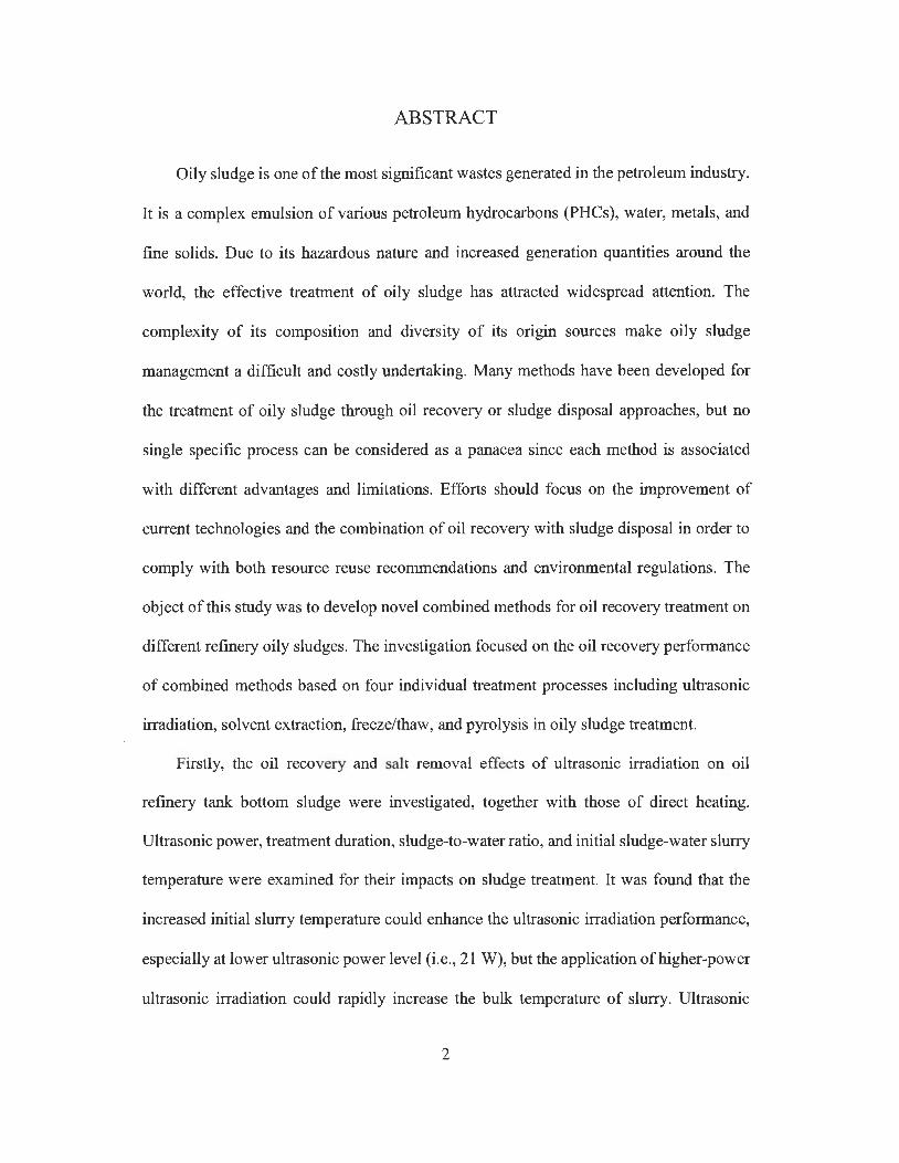
ABSTRACT
Oily sludge is one of the most significant wastes generated in the petroleum industry.
It is a complex emulsion of various petroleum hydrocarbons (PHCs), water, metals, and
fine solids. Due to its hazardous nature and increased generation quantities around the
world, the effective treatment of oily sludge has attracted widespread attention. The
complexity of its composition and diversity of its origin sources make oily sludge
management a difficult and costly undertaking. Many methods have been developed for
the treatment of oily sludge through oil recovery or sludge disposal approaches, but no
single specific process can be considered as a panacea since each method is associated
with different advantages and limitations. Efforts should focus on the improvement of
current technologies and the combination of oil recovery with sludge disposal in order to
comply with both resource reuse recommendations and environmental regulations. The
object of this study was to develop novel combined methods for oil recovery treatment on
different refinery oily sludges. The investigation focused on the oil recovery performance
of combined methods based on four individual treatment processes including ultrasonic
irradiation, solvent extraction, freeze/thaw, and pyrolysis in oily sludge treatment.
Firstly, the oil recovery and salt removal effects of ultrasonic irradiation on oil
refinery tank bottom sludge were investigated, together with those of direct heating.
Ultrasonic power, treatment duration, sludge-to-water ratio, and initial sludge-water slurry
temperature were examined for their impacts on sludge treatment. It was found that the
increased initial slurry temperature could enhance the ultrasonic irradiation performance,
especially at lower ultrasonic power level (i.e., 21 W), but the application of higher-power
ultrasonic irradiation could rapidly increase the bulk temperature of slurry. Ultrasonic
2

irradiation had a better oil recovery and salt removal performance than direct heating
treatment. More than 60% of PH Cs in the sludge was recovered at an ultrasonic power of
75 W, a treatment duration of 6 min, an initial slurry temperature of 25 °C, and a sludge-
to-water ratio of 1 :4, while salt content in the recovered oil was reduced to <5 mg/L,
thereby satisfying the salt requirement in refinery feedstock oil. In general, ultrasonic
irradiation could be an effective method in terms of oil recovery and salt removal from
refinery oily sludge, but the separated wastewater still contains relatively high
concentrations of PH Cs and salt which requires proper treatment.
Two types of ultrasonic assisted extraction (UAE) treatment including UAE probe
(UAEP) system and UAE bath (UAEB) system were investigated for oil recovery from
refinery oily sludge. Their oil recovery efficiencies were compared to that of mechanical
shaking extraction (MSE). Three solvents including cyclohexane (CHX), ethyl acetate
(EA), and methyl ethyl ketone (MEK) were examined as the extraction solvents. The
influence of experimental factors on oil and solvent recovery was investigated using an
orthogonal experimental design. Results indicated that solvent type, solvent-to-sludge (S/S)
ratio, and treatment duration could have significant effects on oil recovery in UAE
treatment. Under the optimum conditions, UAEP treatment can obtain an oil recovery of
68.8% within 20 s, which was higher than that (i.e., 63.7%) by MSE treatments after 60
mins ' extraction. UAEB treatment can also obtain a promising oil recovery within a shorter
extraction duration (i.e. , 15 min) than MSE. The experimental results indicated that two
solvent extraction cycles on oily sludge were sufficient to obtain a satisfactory oil recovery
for all three extraction treatments. The recovered oil by CHX contained the lowest total
petroleum hydrocarbon (TPH) content (i.e., about 50%), while the recovered oil by EA
3
and MEK had relatively higher TPH content (i.e., >80%). UAE was thus illustrated as an
effective and improved approach for oily sludge waste recycling.
A combination of solvent extraction and freeze thaw was examined for recovering oil
from the high-moisture petroleum refinery wastewater treatment pond sludge. Five
solvents including cyclohexane (CHX), dichloromethane (DCM), methyl ethyl ketone
(MEK), ethyl acetate (EA), and 2-propanol (2-Pro) were examined. It was found that these
solvents except for 2-Pro showed a promising oil recovery rate of about 40%, but the
recycling of DCM solvent after oil extraction was quite low. As a result, three solvents
(CHX, MEK and EA) were selected for further combination with freeze/thaw treatment to
improve the quality of recovered oil in terms of its total petroleum hydrocarbon (TPH)
content. The results indicated that the freeze/thaw treatment after solvent extraction could
increase the TPH content in recovered oil from about 40% to 60% for both MEK and EA
extractions, but little effect was observed for CHX extraction. Although the solid residue
after oil recovery had a significantly decreased TPH content, a high concentration of heavy
metals was observed, indicating that this residue may require proper management. In
general, the combination of solvent extraction with freeze/thaw is effective for high-
moisture oily hazardous waste treatment.
The treatment ofrefinery oily sludge through co-pyrolysis with wood waste (sawdust)
was carried out in a fixed-bed reactor. Response surface method (RSM) was applied to
evaluate the main and interaction effect of three experimental factors (i.e., sawdust
percentage in feedstock, temperature, and heating rate) on pyrolysis oil and char yields.
The oil quality in terms of elemental analysis, moisture content, and higher heating value
(HHV) was also investigated. A synergistic effect of co-pyrolysis was found, and the oil
and char yields increased with the sawdust percentage in feedstock. The interaction
4
between heating rate and sawdust percentage as well as between heating rate and
temperature was significant on the yield of pyrolysis oil. The HHV of oil originated from
sawdust increased by 5 MJ/kg due to co-pyrolysis at a sawdust/oily sludge ratio of 3: 1 as
compared to that of sawdust pyrolysis alone. The results indicated that the carbon content
of char increased as increasing sawdust percentage in feedstock. In general, refinery oily
sludge can be used as an additive in the pyrolysis of sawdust for improving the yield and
quality of oil products.
The results of this research indicate that the combined oil recovery methods have the
potential to be applied for the treatment of different complex oily wastes in petroleum
refining industries to meet sustainable development principles.
5

TABLE OF CONTENTS
ABSTRACT .. .. ... ... ....... ..... ... ...... ....... ... ... .. .... ... ...... .. .... ... .... ... .... ... ............. ............. .... ....... 2
LIST OF TABLES ........................ .... .... .. ............ .. ...................... .... ..................... ......... .... 10
LIST OF FIGURES ...................... .... .. .... ......................................................... ... ... .... ....... 12
GLOSSARY ..... .... .. ......... ..... .. .............. .... .. .. ....... ... .... ......... .. ........ .... ......... .... ........ .... ...... 18
ACKNOWLEDGEMENT .... ... .. .. ... ....... .......... .......................... ...... ..... ....... ..... .......... ..... . 21
Chapter 1 General Introduction ........... ...................................... ................................. ...... 22
1.1 Background .. .................... ......... .. .......... .... ................. .......... .............. .... .. ............ ... 22
1.2 Statement of the problem and research objectives ............................... .... .......... .... . 23
Chapter 2 Literature Review * ......................... .... ........... ....................... ...... ...... ............... 29
2.1 . Introduction ..... .......................................... ......... ....... ..................... ....... ... .... ..... .. ... 29
2.2 Source, characteristics and toxicity of oily sludge ..... ... ... .. ........ .... ........ ... ........ ... ... 30
2.2.1 Oily sludge source ........... ..... ............... .... ......... .. .... ... ........... .......................... .. 30
2.2.2 Characteristics of oily sludge ... ........ ............. ......... .. ..... ... .......... .. .......... .. ...... .. 32
2.2.3 Toxicity and impact of oily sludge ....... .... ............... ..... ....... ..... .. .......... ... ..... .... 35
2.3 Overview of sludge treatment methods .. ... ................... .. ...... ............ ..... ................. 37
2.4 Oil recovery methods for oily sludge treatment.. ......... ...... ................ ..... ..... ........... 38
2.4.1 Solvent extraction .. .... .... .............. .. ... .. ... ..... .. ..... ........... ...... ...... ..... ...... ....... ... .. . 38
2.4.2 Centrifugation treatment. ... ....... ............ ...... ..... ... ......... ..... .......... ................ ..... . 41
2.4.3 Surfactant enhanced oil recovery (EOR) .. ..... .... ...... ... ........ ...... ........... ......... ... . 44
2.4.4 Freeze/thaw treatment ............... ..... .. ...... .. ... ........ .... ....... ..................... ............. 47
2.4.5 Pyrolysis treatment ..... .. .... ....... .... ......... ..... ....... ......... ........ .... ... ................. ....... 50
2.4.6 Microwave irradiation ... ......... ....... ..... ................... .... ................ ..... .. ..... ..... ...... 53
2.4. 7 Electrokinetic method ..... ... ....... ..... .. .. ... ... ... ... .. ..... ..... ...... ........... .. .. ...... ............ 56
2.4.8 Ultrasonic irradiation ...... ............... ................ ...... ... ................. ......... ... ... .......... 58
2.4.9 Froth flotation ... .................. ........... ..... ............... .......... ..... .. ... ....... .. ........... .... ... 61
2.5 Oily Sludge Disposal Methods ... .......... ... .. ........ ...... ........... ............. ... .... ......... ... .... 63
2.5.1 Incineration ........... ...................... .. ... .. ... ............ .. ... ................. ....... .. ....... .. ... ..... 63
2.5.2 Stabilization/solidification .................... ..... ... ... .... ........ ......................... ............ 65
2.5.3 Oxidation treatment ....... ................... ..... ... ....... ........ ......... ..... .. .................. ....... 67
2.5.4 Bioremediation ........... ................ .. .... ... ............ ................ ... ........ ....... ... .......... .. 70
6

2.6 Discussion and conclusion ......... ... ............................. .. .................................. .. ... .... 78
Chapter 3 Ultrasonic oil recovery and salt removal from refinery tank bottom sludge * . 84
3 .1 Introduction ............................................................................................................. 84
3.2 Experimental materials and methods ...................................................................... 87
3.2.1 Materials .................... ....... .... .. ........ ... .......... ...... ... .................. .......................... 87
3.2.2 Methods .............. .......... .... .......... ... ... ....... ...... ...... ........... ....... ... ... .. .. .. .. .... ......... 88
3.2.3 Sample analysis ................. ..... .......... ....... .... ....... ......... ..... ............ ... ... ... .... ...... . 90
3.3 Results and discussion .......... .......... ....... ... .................. ....... .. .................. ................. 93
3. 3 .1 Temperature change during ultrasonic treatment.. ........ ........................... ...... .. 93
3.3.2 Effect of temperature and ultrasonic irradiation ............ ................... ............ .... 95
3.3.3 Effects of ultrasonic power and treatment duration ......................................... 99
3 .3 .4 Effect of sludge to water ratio .. ... ......... .. ...................... .. ................................ 106
3 .3 .5 Characteristics of recovered oil ............................................................... ....... 109
3.4 Conclusions .............. .. ... ....... ..... .. ..... .. ........... ..... ..... .............. ......... ........... ............ 112
Chapter 4 Oil recovery from refinery oily sludge through ultrasonic assisted extraction * .. .. ..... ... .............................................. .... ......................... ............................... .......... ...... .. 113
4.1 Introduction .......................... ........... .................................. ........ ............................ 113
4.2 Experimental materials and methods ...... .................. ..... ..... ... ....... ............... .. ....... 115
4.2.1 Materials and reagents ...... .. ..... .......... ...... ...... ........... ........................ ..... ......... 115
4.2.2 Methods .. .... ....... .. ........ ....... ............................ ..... ............ .......... .......... ........... 117
4.3 Results and discussion ................ ..... .... ......... ......... .............. .... ... .. ............. ...... ..... 123
4.3.1 The effect of mechanical shaking extraction (MSE) ... .... .. ... ......... .. ....... .. .. .... 123
4.3.2 Ultrasonic assisted extraction using a probe system (UAEP) ........... ............. 128
4.3.3 Ultrasonic assisted extraction using a bath system (UAEB) ....................... .. . 133
4.4.4 Impact of extraction cycles .... ... ...................................................................... 138
4.3.5 Characteristics ofrecovered oil.. ........ ....................... ........................... ... ....... 141
4.4 Conclusions ........................................................................................................... 148
Chapter 5 A combination of solvent extraction and freeze thaw for oil recovery from refinery wastewater treatment pond sludge * .................................................................. 150
5 .1 Introduction ........................................................................................................... 15 0
5.2 Experimental materials and methods .. .... ... ....... .................................................... 153
5.2.1 Materials .... .... ......................... ... ... .. ......... ... ............. .. .... ... ................ ..... .... .... . 153
5.2.2 Solvent extraction ........................................................................................... 155
7
5.2.3 Freeze/thaw treatment ........ .............. .. ... ....... ...... ... ... .... .... .... ...... .................. .. 157
5.2.4 Sample analysis ..... ............. ... ..... ............ ..... ... ... ..... .... .. .... ... ........ .................. . 159
5.3 Results and discussion ... ......... ...... ................. ........................................ ....... ........ 160
5.3.1 Impact of solvent-to-sludge (S/S) ratio .. ......................... ... ........ .... ............... . 160
5 .3 .2 Impact of extraction duration ......... ............. ... ... .. ......... ........................ ....... ... 165
5.3.3 Extraction cycle .... ..... .... .... ..... ... ................................ .... ...... .. ...... ................... 168
5.3.4 Freeze/thaw enhancement ... .... ... ... .... ...... ........ .......... ...................... ...... ... ...... 169
5.3.5 Characteristics ofrecovered oil and solid residue ........................ ............ ...... 174
5.4 Conclusions ........... ................... .. .. ................ ... .......... ............ ...... ... ........... ............ 179
Chapter 6 Treatment of refinery oily sludge through co-pyrolysis with wood waste ... . 180
6.1 Introduction ............ ........................ ... .......... .... .......... ..... .... ... ....... ...... ..... ... ... ..... ... 180
6.2 Experiment ....................... ..... ...... ................ .... ..... .... ............... .............. ....... ......... 183
6.2.1 Materials .. ..... ......... ... ... ......... .. ...... .............. ....... ... ............ ...... ... ..................... 183
6.2.2 Experimental design ........ ... ... ................ .. .... .. ..... ..................... .... ....... ... ..... ... . 185
6.2.3 Pyrolysis procedure ........... .. ........ .. ....... .. ... .... ......... .. ........ .................. ............ 186
6.2.4 Sample analysis ..... ... ... ........ ............ ... ......... ... ................. .... .... ... .................... 188
6.3 Results and discussion ....... ....... ..... .... ........................................ .......... ... ... ......... .. 189
6.3.1 Thermal gravimetric analysis (TGA) .......... ....................... .. ..... ..... ... ....... ...... 189
6.3.2 Pyrolysis oil yield .... ......... .................. .. .......... .. ............................. ................ . 191
6.3.3 Pyrolysis char yield ........... .. ................... ........... ... ................. .......... .. ... .... ... ... 198
6.3.4 Synergistic effect of co-pyrolysis on oil yield ........ ....................... ... .. ......... ... 201
6.3.5 Pyrolysis product characterization .......................................... ......... .. .. .......... 203
6.4 Conclusions ..... ..... ....... .... .......... ... .... ..... .................................. ..... ..... ......... ...... ... .. 206
Chapter 7 Conclusions and future research ........................... ... .......... .. ........ .............. .... 208
7.1 Thesis conclusions .... ..... ...... ................. ... ........ ................................. .................... 208
7.1.1 The oil recovery and desalting effect of ultrasonic irradiation on oily sludge208
7 .1.2 The combined effect of ultrasonic irradiation and solvent extraction on oil recovery ............. .................. .. .. .. ....... ... .... .. ... ... .................................... .......... .......... 210
7 .1.3 The combined effect of solvent extraction and freeze/thaw on oil recovery . 212
7.1.4 The co-pyrolysis of sawdust with oily sludge for pyrolysis oil production ... 214
7.2 Research achievements ......... ..... .... ......... ....... ......... .... ................ ... ..... .... .............. 217
7.3 Future research ........... ..... .... ...... .... ............. ... ... ... ...... .... .......................... ..... ......... 218
References ........... ... ....... ...... ..... .... .. ...... .. .................. ... ....... ...... ................. ... ....... ............ 220
8

APPENDIX .. .. ... .. .. ... ....... ..... ..... ...... ...... .................. ... .......... ................. .................... ..... 255
Appendix I ............ ........ .. ...... ............ ..... ...... .. .......... .......... ... .................. ...... ... ... .... ... . 255
Appendix II ... ... ... ... .. .... ............... ........ ..................... ... .. Error! Bookmark not defined.
9
LIST OF TABLES
Chapter 2
Table 2.1 Summary and comparison of oil recovery methods ... ......... .................. ......... . 81
Table 2.2 Summary and comparison of oily sludge disposal methods .... ...................... .. 82
Chapter 3
Table 3.1 Characteristics of tank bottom oily sludge sample for ultrasonic treatment ... . 87
Table 3.2 Experimental factors and values of ultrasonic irradiation treatment.. .............. 90
Chapter 4
Table 4.1 Properties of tank bottom oily sludge for extraction treatment.. ......... .... ...... . 116
Table 4.2 Impact factors and levels of each factor in three extraction processes for the
orthogonal experiments .................... .... .... .......... .. ...... .. ....... ............ .... ....... .... ... ... ... 11 7
Table 4.3 A L9 (34) orthogonal array of factors and levels for each extraction process . 118
Table 4.4 Single factor experimental conditions of the three extraction processes .... .... 119
Table 4.5 MSE oil recovery results and statistical analysis .... ..... .... ..... ... ......... ...... ........ 124
Table 4.6 ANOV A for oil and solvent recovery results from MSE ... ..... ... ..... .... ....... .. .. 125
Table 4.7 UAEP oil recovery results and statistical analysis ............ .. ....... .. .. ...... .. ... ... .. 129
Table 4.8 ANOVA for oil and solvent recovery results from UAEP ........... ......... ....... .. 130
Table 4.9 UAEB oil recovery results and statistical analysis ........... ... ..... ... ......... ..... ..... 134
Table 4.10 ANOVA of oil and solvent recovery results from UAEB ... ................ ......... 135
Table 4.11 Properties of crude oil and recovered oil (RO) by different solvents in UAEP
.. .. .... ....................... ....... ...... ...... ...... ...... ... .... .... ... .......... ................. .... ... ... ... .. .... .. ..... 147
10
Chapter 5
Table 5.1 Properties of petroleum refinery wastewater treatment pond sludge ............ . 154
Table 5.2 Experimental factors and values of solvent extraction ............ .. ... .............. ... . 156
Table 5.3 Properties of the original oily sludge and the solid residues after combined
solvent extraction and freeze/thaw treatment ..... ..... ............. ... .. .. ........ .... ....... 178
Chapter 6
Table 6.1 Properties of sawdust and oily sludge .... ........ ..... .............. ................... .. .... .. .. 184
Table 6.2 Experimental array of CCC design for co-pyrolysis experiments and product
yield results ..... .... ... .. .. ..... ........... .. ....... ...... .................. .. .. .. .. .. ... ... .. ... ... ...... ... .. 193
Table 6.3 Statistical parameters obtained from the analysis of variance for the model . 194
Table 6.4 Observed product yields from co-pyrolysis experiments as compared with the
predicted values (temperature: 500 °C, heating rate: 20 °C/min) .. ...... .......... . 203
Table 6.5 Properties of pyrolysis products from co-pyrolysis experiments (heating rate:
20 °C /min, temperature: 500 °C) ....... ......... .... ............................................... 205
11
LIST OF FIGURES
Chapter 2
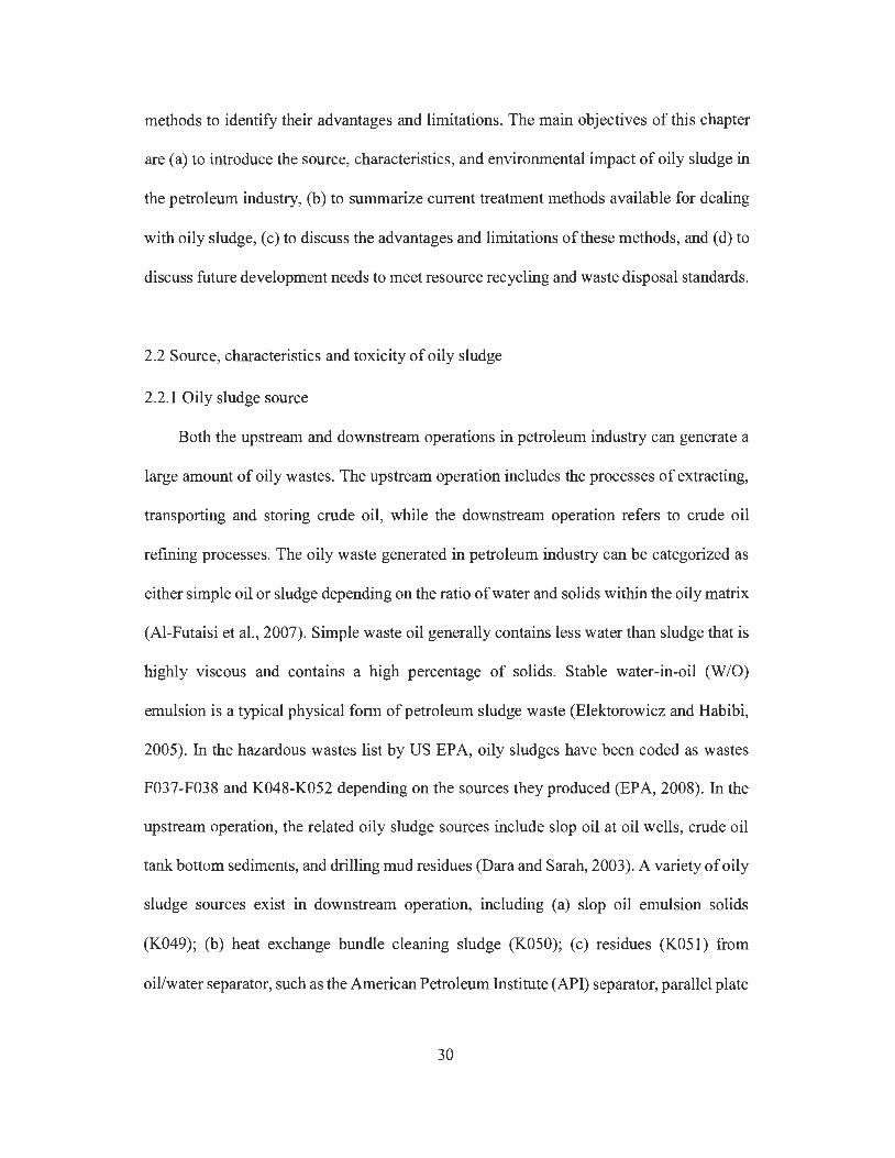
Figure 2.1 Worldwide daily refining throughputs in recent years .............. .... .......... .. ...... 32
Figure 2.2 Overview of oily sludge treatment methods .. .. ............ .............. ...... .. .. .... ...... .. 37
Figure 2.3 Flow diagram of solvent extraction process (1 : reactor column; 2: distillation
system; 3: solvent recycling tank; 4: compressor and cooling system) ........... 41
Figure 2.4 Schematic view of centrifugation used in oily sludge treatment.. ................... 44
Figure 2.5 Schematic diagram of the mechanism of freeze/thaw-induced demulsification
for W/0 emulsion: (a) original emulsion, (b) water droplets freezing,
expansion and coalescing, ( c) oil phase freezing to form a solid cage, ( d) water
droplets freezing and expanding to break the cage, ( e) emulsion thawing and
water droplets coalescing, and (f) gravitational delamination .... .. ................... 48
Figure 2.6 Typical schematic view of fluidized bed systems used in sludge pyrolysis
treatment. ................................................ .. ........................................................ 52
Figure 2. 7 Schematic view of froth flotation in oil/water separation process (A: Air
control valve; B: Motor; C: Stirrer; D: Skimmed oil collector) ....................... 62
Chapter 3
Figure 3.1 Tank bottom sludge sample ... .. .... .. .......... .. ............................ .. .... .. .. .. .. ....... .... . 88
Figure 3.2 Schematic diagram of the ultrasonic irradiation set-up for oily sludge
treatment. ... ........................ ................ ...... ........... ....................... .. ....... .. ...... ... ... 90
Figure 3.3 Temperature change in oily sludge-water slurry mixture treated by ultrasonic
irradiation ( experimental condition: sludge to water ratio of 1 :4 and initial
slurry temperature of 25°C) ... ... ........ .. .... ................. ...... .. ............ ..... .. .... .... ... .. 94
12
Figure 3 .4 Three layers separated from ultrasonic irradiation treatment on oily sludge .. 94
Figure 3.5 Effect of direct heating on oily sludge treatment at different temperatures, (a)
oil recovery rate and salt content in recovered oil, (b) TPH and salt
concentration in wastewater ( error bar represents standard deviation) ............ 96
Figure 3.6 Effect of ultrasonic irradiation on oily sludge treatment at different initial
slurry temperatures, (a) oil recovery rate, (b) salt content in recovered oil, (c)
TPH concentration in wastewater, and ( d) salt content in wastewater
( experimental condition: treatment duration of 6 min and sludge to water ratio
of 1 :4; error bar represents standard deviation) ... ..... .. ............ ......................... 98
Figure 3. 7 Effect of ultrasonic irradiation duration on oily sludge treatment, (a) oil
recovery rate, (b) salt content in recovered oil, ( c) TPH concentration in
wastewater, and ( d) salt content in wastewater ( experimental condition: sludge
to water ratio of 1 :4 and initial slurry temperature of 25°C; error bar represents
standard deviation) ................. ..... ........ ....... ..... ...................... .... ... ..... .. ........... 100
Figure 3.8 Mixtures of oily sludge and water, (a) before ultrasonic treatment, (b) after
treatment under ultrasonic power of 21 W and duration of 2 min, ( c) after
treatment under ultrasonic power of 75 W and duration of 6 min ( experimental
condition: sludge to wat er ratio of 1 :4 and initial slurry temperature of 25°C)
..... .... ...................... ... .. ..... ....... ....... ............. ...... .. .... .. ....... ........ .... .. .. .. ... .......... 101
Figure 3.9 Wastewater generated from oil recovery treatment using different ultrasonic
irradiation powers and durations ......... .. .......... .... ....... ...... ... ...................... ..... 104
Figure 3.10 Effect of sludge to water ratio on the performance of oily sludge treatment by
ultrasonic irradiation, ( a) oil recovery rate, (b) salt content in recovered oil, ( c)
TPH concentration in wastewater, and ( d) salt content in wastewater
13
( experimental condition: treatment duration of 6 min and initial slurry
temperature of 25°C; error bar represents standard deviation) ........... ........... 108
Figure 3.11 Distribution of PHCs fractions and TPH in different hydrocarbon samples,
(a) PHCs fraction percentage, (b) TPH percentage (error bar represents
standard deviation) ............................... .... ........ ........ ... ... .... ............. .. .. ........... 111
Chapter 4
Figure 4 .1 Experimental setups of the three different extraction processes ........... ... ..... 121
Figure 4.2 Influence of experimental factors on the (a) oil and (b) solvent recovery in
MSE process ...... ....... ... .. .. ... ............... ... .. ...... .. ............ ....... ...... .. ...... ...... ..... .. . 124
Figure 4.3 Results of single-factor experiments of MSE ....... ...... ............. ... ... ............... 127
Figure 4.4 Influence of experimental factors on the (a) oil and (b) solvent recovery in
UAEP process .... .. .. ... .................... ............ .. .... .............. ....... ..... ... .. ........ ...... .. 129
Figure 4.5 Results of single-factor experiments of UAEP .. .......... ... .... ... ... ... ... .... ........ .. 132
Figure 4.6 Influence of experimental factors on the (a) oil and (b) solvent recovery in
UAEB process ..... .... .. ...................................... ..... .. .... ................. ......... ......... . 134
Figure 4.7 Results of single-factor experiments ofUAEB ............ ..... .... .. ... ................... 138
Figure 4.8 Effect of extraction cycles on oil recovery in (a) MSE, (b) UAEP, and (c)
UAEB treatment ...... ..... ... .. .......... .. ... .. .......... .................... ...... ...... ................ .. 140
Figure 4.9 Recovered oils by different solvents from UAEP treatment ..... .... .. .. ............ 143
Figure 4.10 TPH recovery (a) and TPH content in recovered oil (b) of three extraction
processes (MSE: SIS ratio of 4: 1, shaking speed of 250 rpm, and duration of
60 mins; UAEP: SIS ratio of 4:1, ultrasonic power of21 W, and duration of20
14

s; UAEB: S/S ratio of 4: 1, duration of 15 min, and bath temperature of 20 °C)
........... ... ....... ... ....... ..... .... ................................................................................ 144
Figure 4.11 Distribution of PH Cs fractions in the recovered oil by using three solvents in
(a) MSE, (b) UAEP, and (c) UAEB (MSE: S/S ratio of 4:1, shaking speed of
250 rpm, and duration of 60 mins; UAEP: S/S ratio of 4: 1, ultrasonic power of
21 W, and duration of 20 s; UAEB: S/S ratio of 4: 1, duration of 15 min, and
bath temperature of 20 °C) ............. .................. ........ ... ...... .................. .. .... ..... 146
Chapter 5
Figure 5.1 Dredged oily sludge from a petroleum refinery wastewater treatment pond 154
Figure 5.2 Freeze treatment on different extractants at -20 °Cina fridge .... ............. .... 159
Figure 5.3 Flow chart of combined solvent extraction and freeze/thaw treatment ........ 159
Figure 5.4 Effect of solvent to sludge ratio on solvent extraction performance, (a) oil
recovery rate, (b) solvent recovery rate, ( c) waste reduction rate ( experimental
condition: extraction duration of 120 min at 25 °C; error bar represents
standard deviation, n=3) ............ .. .. ............... ........... ... ......................... .... ....... 163
Figure 5.5 Extractant of extraction treatments using different solvents ....... .................. 164
Figure 5.6 Effect of extraction duration on solvent extraction performance, (a) oil
recovery rate, (b) solvent recovery rate, ( c) waste reduction rate ( experimental
condition: solvent-to-sludge ratio (v/m) of 4: 1 at 25 °C; error bar represents
standard deviation, n=3) ... ... ....... .................. ..... ....... .. ... ...... ......... .......... ........ 168
Figure 5. 7 Effect of solvent extraction cycles on oil recovery rate ........... .......... ........... 169
Figure 5.8 Effect of freeze/thaw enhanced solvent extraction and the comparison of
separated water level from the extractant with freeze/thaw treatment (left
15
yellow bar) and without freeze/thaw treatment (right red bar), (a) ice lattice
formation in the extractant from MEK extraction, (b) CHX extraction, ( c)
MEK extraction, and ( d) EA extraction ........................................... .... .... ...... 171
Figure 5.9 Effect of freeze/thaw (FIT) treatment on (a) TPH content in recovered oil by
solvent extraction and (b) TPH content in recovered oil as a function ofF/T
cycle ........ ..... .... .. .. ... ... .. .................. ..... ......................... .. ...... .... .. .................... 174
Figure 5.10 Distribution of PH Cs fractions in fresh crude oil and the recovered oil by
using the combination of solvent extraction with freeze/thaw ....................... 175
Figure 5 .11 Solid residues from refinery wastewater pond sludge after combined solvent
extraction and freeze/thaw treatment ............................................................. 1 77
Chapter 6
Figure 6.1 The feedstock of sawdust and oily sludge (left: before mixed; right after
mixed) ............................... ................... ........ ... .. ....... ... ........ .............. ........ ... 184
Figure 6.2 The fixed-bed reactor designed for the co-pyrolysis of sawdust with oily
sludge ................................. ... .. ..................................................................... 187
Figure 6.3 Schematic diagram of fixed-bed pyrolysis reactor.. ...................................... 188
Figure 6.4 TG and DTG curves of (a) sawdust and (b) oily sludge (solid line: TG; dashed
line: DTG) .................................................................................................... 190
Figure 6.5 Liquid oil product from the pyrolysis of sawdust alone (left), mixture of
sawdust (75 wt.%) and oily sludge (25 wt.%), and oily sludge alone (right)
(Heating rate: 20 °C/min; Temperature: 500 °C) .......... ................ ..... .......... 192
Figure 6.6 The main effects of single factors on pyrolysis oil yield: (a) sawdust
percentage (temperature: 500 °C, heating rate: 12.5 °C/min), (b) temperature
16
(sawdust percentage: 50 wt.%, heating rate: 12.5 °C/min), and (c) heating
rate (sawdust percentage: 50 wt.%, temperature: 500 °C) ........................... 197
Figure 6. 7 The interaction effect of experimental factors on pyrolysis oil yield ........... 198
Figure 6.8 The main effects of single factors on char yield: (a) sawdust percentage
(temperature: 500 °C, heating rate: 12.5 °C/min), (b) temperature (sawdust
percentage: 50 wt.%, heating rate: 12.5 °C/min), and (c) heating rate
(sawdust percentage: 50 wt.%, temperature: 500 °C) ............. ........ ... ... .... ... 200
Figure 6.9 The interaction effect of experimental factors on char yield .................... .... 201
Figure 6.10 The solid product from co-pyrolysis of sawdust with oily sludge at a mass
ratio of 3: 1 ( 500 °C, 20 °C/min) .... ... .... ..... ............. .. ..... ....... ..... .. ............. ... 205
17

GLOSSARY
Letters
2-Pro
ANOVA
API
ASTM
CCC
CCME
CHX
DCM
DTG
EA
EOR
EPA
FIT
GC
GC-FID
2-Propane
Analysis of variance
American Petroleum Institute
American Society for Testing and Materials
Decane
Hexadecane
Tetratriacontane
Pentacontane
Central composite circumscribed
Canadian Council of Ministers of Environment
Cyclohexane
TPH concentrations (mg/g) in the recovered oil layer
TPH concentrations (mg/g) in the original sludge
Dichloromethane
Differential thermal-gravimetric analysis
Ethyl acetate
Enhanced oil recovery
Environmental Protection Agency
Freeze thaw
Gas chromatograph
Gas chromatograph with flame ionization
18

ICP
K
MAE
MEK
MSE
ORi
PAHs
PH Cs
PLE
R
RCRA
RO
Ro
RSM
S/S
SDS
SFE
B
SW
TGA
Inductively coupled plasma
The sum of percentage of the effect of impact factor at each level
Microwave assisted extraction
Methyl ethyl ketone
Mass of recovered oil (g)
Mass of residues (g)
Mass of oily sludge (g)
Mechanical shaking extraction
The oil recovery rate of the ith extraction
Poly aromatic hydrocarbons
Petroleum hydrocarbons
Pressurized liquid extraction
Extreme difference
Resource Conservation and Recovery Act
Recovered oil
Oil recovery rate
Response surface methodology
Solvent-to-sludge
Sodium dodecyl sulphate
Supercritical fluid extraction
The mass percentage of oily sludge in mixture (wt.%)
Sludge-to-water
Thermos-gravimetric analysis
19
TPH
UAE
UAEB
UAEP
W/0
Xi, Xj
y
Yproduct
Yproduct I
Yproduct2
a
/Jo
/Ji
/Ju
/Ju
Total petroleum hydrocarbon
Ultrasonic assisted extraction
Ultrasonic assisted extraction bath
Ultrasonic assisted extraction probe
water-in-oil
The independent variables
The response variable
The theoretical yield of co-pyrolysis product (wt.%)
The yield of sawdust during co-pyrolysis (wt.%)
The yield of oily sludge during co-pyrolysis (wt.%)
The mass percentage of sawdust in mixture (wt.%)
The intercept coefficient of the model
The linear coefficient of the model
The quadratic coefficient of the model
The interaction coefficient of the model
20

ACKNOWLEDGEMENT
This thesis reflects the final part of my Ph.D. study at the University of Northern
British Columbia. First of all, I am grateful to my supervisor, Dr. Jianbing Li, for
support and direction throughout my Ph.D. study. His academic advising,
professional knowledge, and insightful thoughts not only benefit my Ph.D. study,
but also will help me greatly in my future research career.
I would like to thank Dr. Joselito M. Aracena, Dr. Ron Turing, Dr. Jueyi Sui, and Dr.
Liang Chen for being my supervisory committee members. I greatly appreciate their
insightful comments, guidance, and suggestions.
Thanks goes to fellow Ju Zhang, Siddhartho Shekhar Paul, and Gopal Saha for their
kind sharing their knowledge, skills, and thoughts during the entire research
process. Thanks to visiting scholars: Xinying Zhang and Shuhui Huang for their help
with designing experimental apparatus, securing equipment, and conducting
experiments.
I would also like to thank Quanji Wu, Dominic Reiffarth, Bill McGill, Heath de la
Giroday, and Conan Ma for their support with sample analysis at Northern
Analytical Laboratory and sample delivery at ChemStore. Furthermore, I wish to
thank Alida Hall for her helpful instructions as the supervisor of my teaching
assistant position at UNBC.
Special thanks go to my wife, parents, and friends for their encouragement and
support throughout my entire Ph.D. study. I wish to thank Dr. Xinghui Xia from
Beijing Normal University and Dr. Haobo Hou from Wuhan University for
supporting me to study at UNBC.
Appreciation is extended to Prince George Husky Refinery for providing various oily
sludge samples to my research.
Enormous thanks is extended to the Natural Sciences and Engineering Research
Council of Canada, Environment Canada, and UNBC for providing financial support.
21
Chapter 1 General Introduction
1.1 Background
Petroleum industries generate considerable quantities of oily sludge during various
oil production processes including crude oil exploration, conveyance, storage, and
downstream refining. It is estimated that each refinery generates an annual average of
30,000 tons of oily sludge (EPA, 1991). The oily sludge production volume is expected to
increase as a result of the ascending demand on refined petroleum products worldwide (BP,
2012). The quantities and properties of oily sludge depend on the nature of crude oil,
storage conditions, down-stream processing schemes, and the design of refining apparatus.
Generally, oily sludge physically exists as a stable water-in-oil (W/0) emulsion, which
consists of water, solids, various petroleum hydrocarbons (PHCs), and metals. The
stability ofW/0 emulsions depends mainly on a protective film that inhibits water droplets
from coalescing with each other. This interfacial film is composed of many natural
emulsifiers such as some PHCs constituents (e.g., asphaltenes and resins), fine solids, oil
soluble organic acids, and other finely divided materials (Hu et al., 2013). The chemical
composition of oily sludge can vary over a wide range, depending on sources, processing
scheme, and equipment and reagents used in refining process. Typically, oily sludge
contains 15-50% of total petroleum hydrocarbon (TPH, or oil), 30-85% of water, and 5-
46% of solids. Due to the existence of carcinogenic and mutagenic poly aromatic
hydrocarbons (PAHs) and toxic heavy metals (e.g., chromium, cadmium, and lead) in oily
sludge, it has been categorized as a hazardous waste by many environmental regulations
world widely ( da Rocha et al., 201 O; Liu et al., 2009). Any improper disposal of oily sludge
could cause serious environmental contamination and pose threats to the health of
22
surrounding receptors. Due to its hazardous nature and increasing quantities around the
world, there is a pressing need to develop effective, economically feasible, and
environmentally friendly techniques to address the oily sludge problem in petroleum
industries.
1.2 Statement of the problem and research objectives
In the past decades, oily sludge is sent to sludge pit or landfills for natural attenuation
(da Silva et al., 2012). However, this approach is associated with various disadvantages
such as low degradation efficiency, too time-consuming, high risks of environmental
contamination, and occupying large amount of valuable land resources (da Silva et al.,
2012; Hu et al., 2013). It is also not suitable in cold regions such as the vast area of Canada
because the activity of PHCs degradation microbes could be compromised in cold
environment (Yang et al., 2009). Moreover, the becoming more restrictive environmental
regulations (e.g., Ontario Environmental Protection Act, Regulation 347 and Resource
Conservation and Recovery Act) have been enacted, by which the direct land treatments
for hazardous wastes disposal are limited.
Considering oily sludge contains relatively high amount of oil, oil recovery could be
the most desirable approach for its treatment (Elektorowicz and Habibi, 2005; da Silva et
al., 2012). The oil recovery technology should be capable of recovering oil in a form that
can be sent to a refinery for processing to produce high value petrochemical products,
while the residues of oily sludge can be easily cleaned up. This approach not only can reuse
the valuable energy content, but also can significantly reduce the volume and toxic level
of waste, alleviating its negative impact on the environment. In recent years, a number of
physical, chemical, and biological processing methods have been proposed for the oil
23

recovery from oily sludge (Hu et al., 2013). These novel methods including ultrasonic
irradiation, microwave irradiation, pyrolysis, electrokinetic processing, biosurfactant
demusification, freeze/thaw demusification, and solvent extraction (Hu et al., 2013). These
methods are associated with various advantages and limitations (da Silva et al., 2012; Hu
et al., 2013). For example, microwave and pyrolysis treatment can greatly reduce the
volume of oily sludge, but the energy consumption of these approaches is high; solvent
extraction can recover most useable PH Cs from oily sludge but this method requires large
amount of organic solvent to achieve promise oil recovery rate (Hu et al., 2013). Moreover,
none of these methods is universally applicable because the properties of oily sludges from
different sources and/or petrochemical production schemes vary significantly. Single
treatment might not be effective in treating complex oily sludge, and thus the combined
treatment methods are needed to address the limitations of each single method.
Among various oil recovery methods, ultrasonic irradiation, solvent extraction,
freeze/thaw, and pyrolysis represent promising techniques due to their inherent merits such
as short treatment duration compared to biodegradation, environmentally friendly, and
promising oil recovery performance. Ultrasonic irradiation has been used for the removal
of adsorbed materials from solid particles and the demulsification of stable water/oil (W/0)
emulsions (Xu et al., 2009; Zhang et al., 2012). The microbubbles cavitation spawned
during ultrasonic irradiation does not only generate strong shear force in the bulk system
but also generate large amount of heat in a few microseconds, and could thus improve the
separation of oil from oily sludge (Li et al., 2013). It also has been reported effective in
reducing the salt and water amount in crude oils (Ye et al., 2008; Gholam and Dariush,
2013), however, its desalting effect on the recovered oil from oily sludge is yet to known.
Solvent extraction is a simple and effective process that can separate PHCs from various
24

matrix, has been proven successful for oily wastes treatment (Zubaidy and Abouelnasr
2010; Taiwo and Otolorin 2009). In this process, oily wastes and solvent are mixed in an
appropriate proportion to ensure adequate miscibility of oil in solvent, while most water
and solids are rejected as unwanted impurities which can be removed by gravitational
settling or centrifugation. The oil and solvent mixture can then be separated by distillation
for the purpose of both oil and solvent recycling (Al-Zahrani and Putra, 2013). Moreover,
freeze/thaw treatment has been proven as a cost-effective dewatering process for the break
ofW/0 emulsion. The volume expansion of water droplets when turning to ice could cause
the coalescence of emulsified water droplets and the change of interfacial tension between
water and oil phases, and these were the main driving forces of dewatering (Lin et al.,
2007). Pyrolysis is an effective thermo-chemical conversion process during which oily
wastes is heated in a closed oxygen-free reactor system at moderate operating temperatures
(i.e., usually 200 to 500 °C) (Isahak et al., 2012). This process can convert organic wastes
into combustible gases, pyrolysis oil, and char. Combustible gas and pyrolysis oil can be
used for energy supply and char after proper modification can be used as an adsorbent for
pollution control (Bernardo et al., 2012).
In order to effectively handle complex oily sludge, it is important to improve these
oil recovery techniques. The combinational utilization of these techniques could be an
alternative solution for the improvement of single method. Ultrasonic assisted extraction
(UAE) uses the turbulence and heat generated by ultrasonic irradiation to facilitate the
mixing of solvents and PHCs in various matrixes, which could significantly reduce the
extraction time and increase the extraction efficiency (Bossio et al., 2008). In treating high
moisture oily sludge, solvent extraction treatment alone is not sufficient to remove the
highly emulsified water in the extraction matrix. The combined usage of solvent extraction
25
and freeze/thaw could be a solution to remove the undesirable emulsified water. Moreover,
the co-pyrolysis of organic wastes (i.e., waste tyres, used lubricating oils, and municipal
sewage sludge) with various biomass has been reported effective in improving the quantity
and/or the quality of recovered oil without any change in the system process (Kar, 2011;
Onal et al., 2014). Therefore, investigating the combined effect of different techniques on
oil recovery from oily sludge is of great importance and could provide more advanced
solutions for the oily wastes treatment in petrochemical industries.
The main objective of this thesis is to develop novel combined physical-chemical
techniques based on ultrasonic irradiation, freeze/thaw, solvent extraction, and pyrolysis
treatments for the oil recovery from various refinery oily sludge. The specific research
objectives include:
(1) Investigating the oil recovery and desalting effect of ultrasonic irradiation on
refinery tank bottom sludge. The effect of influential factors including ultrasonic power,
treatment duration, sludge-to-water (S/W) ratio, and sludge-water slurry temperature were
studied to examine their impacts on the treatment performance. In addition, the
concentration of PH Cs and salt in wastewater generated as a by-product from this treatment
were quantified.
(2) Examining the effect of ultrasonic assisted extraction on oil recovery from tank
bottom sludge. The oil recovery performance of two types of UAE system including
ultrasonic assisted extraction probe (UAEP) system and ultrasonic assisted extraction bath
(UAEB) system were studied compared to that of mechanical shaking extraction (MSE)
treatment. A number of factors including solvent type, solvent-to-sludge (S/S) ratio,
ultrasonic irradiation duration, ultrasonic power, ultrasonic bath temperature, and the
26
number of extraction cycles, were investigated for their individual effect on the treatment
using orthogonal experimental design.
(3) Developing a combinational solution of solvent extraction and freeze/thaw for the
oil recovery from high moisture dredged sludge from refinery wastewater pond. The oil
recovery rate, solvent recovery rate, and the waste reduction rate of sludge were examined.
The performance of freeze thaw treatment on improving the quality of recovered oil in
terms of its TPH content. Three groups of experiments were conducted, including
freeze/thaw treatment alone, solvent extraction alone, and combined solvent extraction
with freeze/thaw. The TPH content and PHCs fraction distribution in the recovered oil
were reported, and the properties of solid residue as the by-product of the treatment process
were analyzed.
( 4) Evaluating the co-pyrolysis process of oily sludge with biomass to improve the
generation ofbio-oil and bio-char. The synergistic effect of the oily sludge addition on the
bio-oil derived from pyrolysis of sawdust was investigated. Co-pyrolysis of sawdust with
oily sludge was carried out in a fixed-bed reactor under different pyrolysis conditions. The
effect and interaction of different influential factors including sawdust addition amount,
temperature, and heating rate on the yield of bio-oil was investigated by the response
surface methodology (RSM). The characteristics of products from the co-pyrolysis of
sawdust with oily sludge were determined to evaluate their possibility of being a potential
energy source and petrochemical feedstock.
It should be noted that two different oil recovery calculation methods were used in
this thesis. In Chapter 3, the oil recovery and desalting effect of ultrasonic irradiation on
oily sludge was investigated. This research project was a successive study to the previous
research project "Oil recovery from refinery oily sludge via ultrasound and freeze/thaw",
27
so the oil recovery was calculated using the same equation reported by Zhang et al. (2012)
as the ratio of TPH mass in the recovered oil to the TPH mass in the original oily sludge;
In Chapter 4-6, the oil recovery/yield was calculated as the mass percentage ratio of
recovered oil to that of original oily sludge, which is a widely reported oil recovery
calculation method in literatures.
28

Chapter 2 Literature Review *
* This review has been published as: Hu, G.J., Li, J.B., and Zeng, G.M., 2013. Recent
development in the treatment of oily sludge from petroleum industry: A review. Journal
o_f Hazardous Materials, 261 , 470-490.
2.1. Introduction
Oily sludge, generated from petroleum production processes in petrochemical
industry at a large quantity, is one of the major wastes that has received increasing attention
in recent years. It contains a high concentration of petroleum hydrocarbons (PH Cs) and
other recalcitrant components. As being recognized as a hazardous waste in many countries,
the improper disposal or insufficient treatment of oily sludge can pose serious threats to
the environment and human health (da Silva et al., 2012; Xu et al., 2009). The effective
management of oily sludge has become a worldwide problem due to its hazardous nature
and increasing production quantity around the world. During the past years, a variety of
oily sludge treatment methods have been developed, such as landfarming, incineration,
solidification/stabilization, solvent extraction, ultrasonic treatment, pyrolysis,
photocatalysis, chemical treatment, and biodegradation (Xu et al., 2009; Mrayyan and
Battikhi, 2005; Liu et al. , 2009; Mater et al. , 2006; da Rocha et al. , 2010; Roldan-Carrillo
et al. , 2010; Zubaidy and Abouelnasr, 2010; Yan et al., 2012) . By employing these
technologies, the contents of hazardous constituents can be reduced or eliminated, and its
deleterious environmental and health impacts can thus be mitigated. However, due to the
recalcitrant nature of oily sludge, few technologies can reach a compromised balance
between satisfying strict environmental regulations and reducing treatment costs. As a
result, there is a need for a comprehensive discussion of current oily sludge treatment
29
methods to identify their advantages and limitations. The main objectives of this chapter
are (a) to introduce the source, characteristics, and environmental impact of oily sludge in
the petroleum industry, (b) to summarize current treatment methods available for dealing
with oily sludge, (c) to discuss the advantages and limitations of these methods, and (d) to
discuss future development needs to meet resource recycling and waste disposal standards.
2.2 Source, characteristics and toxicity of oily sludge
2.2.1 Oily sludge source
Both the upstream and downstream operations in petroleum industry can generate a
large amount of oily wastes. The upstream operation includes the processes of extracting,
transporting and storing crude oil, while the downstream operation refers to crude oil
refining processes. The oily waste generated in petroleum industry can be categorized as
either simple oil or sludge depending on the ratio of water and solids within the oily matrix
(Al-Futaisi et al. , 2007). Simple waste oil generally contains less water than sludge that is
highly viscous and contains a high percentage of solids. Stable water-in-oil (W/0)
emulsion is a typical physical form of petroleum sludge waste (Elektorowicz and Habibi,
2005). In the hazardous wastes list by US EPA, oily sludges have been coded as wastes
F037-F038 and K048-K052 depending on the sources they produced (EPA, 2008). In the
upstream operation, the related oily sludge sources include slop oil at oil wells, crude oil
tank bottom sediments, and drilling mud residues (Dara and Sarah, 2003). A variety of oily
sludge sources exist in downstream operation, including (a) slop oil emulsion solids
(K049); (b) heat exchange bundle cleaning sludge (KOSO); ( c) residues (K05 l) from
oil/water separator, such as the American Petroleum Institute (API) separator, parallel plate
30

interceptor, and corrugated plate interceptor (CPI); (d) sediments (K052, K169, and Kl 70)
at the bottom ofrail, truck, or storage tanks; (e) sludge (K048) from flocculation-flotation
(FFU), dissolved air flotation (DAF), or induced air flotation (IAF) units, and (f) sludges
(F037 and F038) from the primary and secondary separation of solids/water/oil during the
storage or treatment of process refining wastewaters (van Oudenhoven et al., 1995). In
particular, the bottom sediments in crude oil storage tanks represent the most intensively
studied oily sludge in literatures. Prior to being refined to petroleum products, crude oil is
temporarily housed in storage tanks where it has a propensity to separate into heavier and
lighter petroleum hydrocarbons (PHCs). The heavier PHCs often settle along with solid
particles and water (Ayotamuno et al. , 2007). This mixture of oil, solids, and water
deposited at the storage tank bottom is known as oily sludge (Greg et al., 2004). It is
removed during tank cleaning operations and sent for further treatment or disposal.
The sludge quantity generated from petroleum refining processes depends on several
factors such as crude oil properties ( e.g., density and viscosity), refinery processing scheme,
oil storage method, and most importantly, the refining capacity. According to an
investigation conducted by US EPA, each refinery in the United States produces an annual
average of30,000 tons of oily sludge (EPA, 1991). In China, the annual production of oily
sludge from petrochemical industry is estimated to be 3 million tons (Wang et al. , 2012).
Generally, a higher refining capacity is associated with a larger amount of oily sludge
production. It has been estimated that one ton of oily sludge waste is generated for every
500 tons of crude oil processed (van Oudenhoven et al. , 1995). Figure 2.1 shows the global
refining throughputs in recent years, and it is estimated that that more than 60 million tons
of oily sludge can be produced every year and more than 1 billion tons of oily sludge has
been accumulated worldwide (da Silva et al., 2012; BP, 2012). It is also expected that the
31
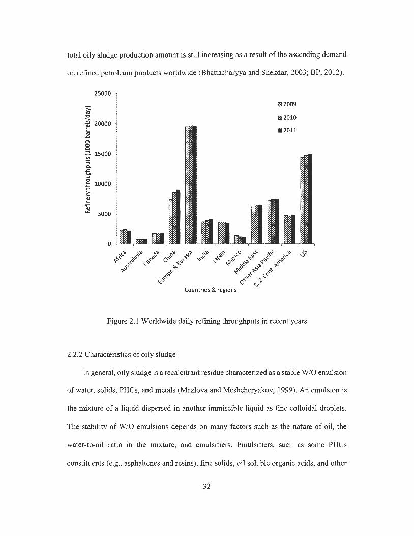
total oily sludge production amount is still increasing as a result of the ascending demand
on refined petroleum products worldwide (Bhattacharyya and Shekdar, 2003; BP, 2012).
25000
-;:: ISi 2009 ra
"C ~2010 ....... "' 20000 a:i ... ... ra
..c 0 0 0 ~ 15000 "' ... ::, C. .c t>.O ::, 0 ... 10000 .c ... >-... Q) C
I+: Q) a: 5000
0
Countries & regions
Figure 2.1 Worldwide daily refining throughputs in recent years
2.2.2 Characteristics of oily sludge
In general, oily sludge is a recalcitrant residue characterized as a stable W /0 emulsion
of water, solids, PHCs, and metals (Mazlova and Meshcheryakov, 1999). An emulsion is
the mixture of a liquid dispersed in another immiscible liquid as fine colloidal droplets.
The stability of W /0 emulsions depends on many factors such as the nature of oil, the
water-to-oil ratio in the mixture, and emulsifiers. Emulsifiers, such as some PHCs
constituents (e.g., asphaltenes and resins), fine solids, oil soluble organic acids, and other
32

finely divided materials, can form a protective film around the surface of water droplets
that inhibits them from coalescing with each other (Yang et al., 2009; Kralova et al., 2011 ).
The pH value of oily sludge is usually in a range between 6.5 and 7.5 and its chemical
composition varies over a wide range, depending on crude oil source, processing scheme,
and equipment and reagents used in refining process (da Silva et al., 2012). For example,
the total petroleum hydrocarbon (TPH) contents in oily sludge can range from 5% to 86.2%
by mass, but more frequently in the range of 15-50% (Tahhan et al., 2011; Biswal et al.,
2009; Mohan and Chandrasekhar, 2011; Liu et al., 2010; Liu et al., 2012), whereas the
contents of water and solids are in the range of 30-85% and 5-46%, respectively
(Ramaswamy et al., 2007). The PHCs and other organic compounds in oily sludge can be
generally classified into four fractions, including aliphatics, aromatics, nitrogen sulphur
oxygen (NSO) containing compounds, and asphaltenes (Mrayyan and Battikhi, 2005;
Reddy et al., 2011). The aliphatics and aromatic hydrocarbons usually account for up to
75% of PHCs in oily sludge (Ward et al., 2003), and their most common compounds
include alkanes, cycloalkanes, benzene, toluene, xylenes, naphthalene, phenols and
various polycyclic aromatic hydrocarbons (PAHs) (e.g., methylated derivatives of fluorine,
phenanthrene, anthracene, chrysene, benzofluorene, and pyrene) (Kriipsalu et al., 2008).
The NSO fraction contains polar compounds such as naphthenic acids, mercaptans,
thiophenes and pyridines (Kriipsalu et al., 2008). The nitrogen (N) content accounts for
less than 3% in oily sludge, and most of them are contained in the distillate residue as part
of asphalt and resin fraction. The sulphur (S) content can be in the range of 0.3-10%
whereas the oxygen (0) content is usually less than 4.8% (Kriipsalu et al., 2008).
Asphaltenes are mixtures of pentane-insoluble and colloidal compounds including poly
aromatic and alicyclic molecules with alkyl substitutes (usually methyl groups), and they
33
vary in molecular weight between 500 and several thousand (Tavassoli et al. , 2012).
Asphaltenes and resins can be responsible for the stability of oily sludge emulsion since
these constituents contain hydrophilic functional groups and consequently can act as
lipophilic emulsifiers (Rondon et al., 2006). Usually, oily sludge is composed of 40-52%
alkanes, 28-31 % aromatics, 8-10% asphaltenes, and 7-22.4% resins by mass (Mishra et al.,
1999; van Hamme et al., 2000).
As a result of diverse chemical compositions in oily sludge, its physical properties
such as density, viscosity, and heat value can vary significantly. The property
measurements obtained from one oily sludge source cannot be applied to another source
or to another sludge sample of the same source but collected on a different day or different
location (API, 2010). However, a key factor affecting the physical properties of oily sludge
is the polarity and molecular weight of chemical constituents in sludge, and it is possible
to make an empirical estimation of physical properties based on the chemical compositions
of sludge (API, 1992; API, 2010). In addition to organic chemical components, oily sludge
also contains a variety of heavy metals resulted from different sources. The species and
concentrations of these heavy metals could vary over a wide range as similar to organic
compounds. According to a report from American Petroleum Institute (API) (API, 1989),
metal concentrations in oily sludge obtained from petroleum refineries are generally 7-80
mg/kg for zinc (Zn), 0.001-0.12 mg/kg for lead (Pb), 32-120 mg/kg for copper (Cu), 17-
25 mg/kg for nickel (Ni), and 27-80 mg/kg for chromium (Cr). It is possible that a very
high concentration of heavy metals could be found in oily sludge. For example, the metal
concentration in oily sludge from refineries was reported in recent literatures as 1299
mg/kg for Zn, 60200 mg/kg for iron (Fe), 500 mg/kg for Cu, 480 mg/kg for Cr, 175 mg/kg
34

for Ni, and 565 mg/kg for Pb, respectively (Reddy et al., 2011; Marin et al., 2006; Smadar
et al., 2001; Otidene et al., 2010).
2.2.3 Toxicity and impact of oily sludge
Due to the existence of high-concentration toxic substances, the improper disposal of
oily sludge can pose serious threats to the receiving environment. After entering the
terrestrial environment, oily sludge can disturb the physical and chemical properties of
receiving soils, leading to soil morphological change (Robertson et al., 2007). The oily
sludge contaminated soils may create nutrient deficiency, inhibit seed germination, and
cause restricted growth or demises of plants on contact (Al-Mutairi et al. , 2008). Due to its
high viscosity, oily sludge components can be fixed in soil pores, adsorbed onto the surface
of soil mineral constituents, or form a continuous cover on soil surface (Trofimov and
Rozanova, 2003). These would lead to reduced hygroscopic moisture, hydraulic
conductivity, and water retention capacity (i.e. wettability) of soils (Suleimanov et al. ,
2005; Trofimov and Rozanova, 2003). In particular, the components with higher molecular
weight in sludge and their degradation products could remain near soil surface and form
hydrophobic crusts that decrease water availability and limit water/air exchange (Tang et
al., 2012). A long-term (i.e. several years) hydrophobicity of oily wastes contaminated
agricultural soils has been reported in western Canada although many PHCs-contaminated
soils eventually take up water (Robertson et al. , 2007).
The disposal of oily sludge to the environment could lead to various toxic effects
caused by PH Cs and heavy metals. Most of the heavy metals have a cumulative effect and
are of particular hazard. In terms of PH Cs, the polycyclic aromatic hydrocarbons (PAHs)
are of major concerns since they are genotoxic to humans and other ecological receptors
35
(Robertson et al., 2007). The PHCs in oily sludge could migrate down through the soil
profile and enter groundwater that is linked with other aquatic systems, causing serious
adverse consequences such as reduced diversity and abundance of fish in the aquatic
system (Trofimov and Rozanova, 2003). PHCs in oily sludge could also decrease the
activity of soil enzymes (i.e. hydrogenase and invertase) and pose toxic effects on the soil
microorganisms (Suleimanov et al., 2005). Moreover, after remaining in the terrestrial
environment for an extended period of time, the weathered ( or aged) chemical residues
may appear to resist de-sorption and degradation, and they have considerable time to
interact with soil components (Tang et al. , 2012). Covalent bonding between organic
compounds in sludge residues and humic polymers (e.g., humin, fulvic acid and humic
acid) in soil could form stable dialkylphthalates, long-chain alkanes and fatty acids that are
resistant to microbial degradation (Certini, 2005; Alexander, 2000). Due to the hazardous
nature of oily sludge, many regulations in the world such as the Resource Conservation
and Recovery Act (RCRA) in USA have established strict standards for its handling,
storage and disposal (EPA, 1980). For example, it was regulated that all surface
impoundments which treat or store hazardous wastes must either be double lined or taken
out of service (API, 2010). Even if oily sludge is disposed of in lagoon which is lined with
cement and bricks, problems of odour and fire hazard would still be created (Bhattacharyya
and Shekdar, 2003). Refinery oily sludge deposited in lagoons or landfills has also been
identified as a stationary source of atmospheric volatile organic compounds (VOCs)
pollution (Cheremisinoff and Rosenfeld, 2009). Such air pollutant emissions can create
health risks to facility workers and surrounding communities (Santiago et al., 2002).
36
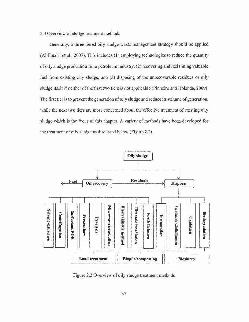
2.3 Overview of sludge treatment methods
Generally, a three-tiered oily sludge waste management strategy should be applied
(Al-Futaisi et al. , 2007). This includes (1) employing technologies to reduce the quantity
of oily sludge production from petroleum industry, (2) recovering and reclaiming valuable
fuel from existing oily sludge, and (3) disposing of the unrecoverable residues or oily
sludge itself if neither of the first two tiers is not applicable (Pinheiro and Rolanda, 2009).
The first tier is to prevent the generation of oily sludge and reduce its volume of generation,
while the next two tiers are more concerned about the effective treatment of existing oily
sludge which is the focus of this chapter. A variety of methods have been developed for
the treatment of oily sludge as discussed below (Figure 2.2).
Oily sludge
Fuel Oil recovery Residuals
Disposal
; t!:! 5l fr.
.-,J - S' 0 n ~ .~ s ct ,::' t:::f :a- E; ~ ~ B l!!j ; .. "' S" ;· I ;, "' ·1 • - 0 IC 0 =-::;' It·
~ S' • !'ir Q. ct lo( .... & ~ ;;· Q rr! 1:1; = e!.. ...
= I!. 0 19 19 r:; = 11 =-= a '< ... ::t. ~ .. l'I I;' ~ !'ir .. .. 0 = Q ::t. =-... .. !':I l ;: = .. ::t. t:!l!j Iii) -· Iii) ::. 5 0 .. a .. a ::t. 0 = ::t. • 0 $1 =- •• = • = -· & Iii) • " • ,= .. ::. = ! = = ::t. - • 0 • = § = =-
Figure 2.2 Overview of oily sludge treatment methods
37
2.4 Oil recovery methods for oily sludge treatment
Recycling is the most desirable environmental option for handling oily sludge since
it enables petroleum industry to reuse valuable oil for reprocessing and reformulating or
energy recovery. Moreover, recycling of oily sludge can reduce the disposal volume of
hazardous waste outside the industrial zone, prevent the extent of contamination, and
decrease the use of non-renewable energy resources. According to API (1989), the primary
environmental consideration in handling oily sludge should be the maximization of
hydrocarbon recovery. It was reported that in the USA, more than 80% of PHCs wastes
generated within a refinery is recycled, with the remaining 20% managed by an acceptable
disposal method (API, 2010). In general, oily sludge with a high concentration(> 50%) of
oil and a relatively low concentration of solids ( < 30%) are preferable to be recycled (Hahn,
1994). Other studies suggested that oily sludge even containing a relatively low oil content
(> 10%) still merits a treatment of oil recovery (Ramswamy et al., 2007). A number of
methods have been available for recycling hydrocarbons from oily sludge.
2.4.1 Solvent extraction
Solvent extraction has been widely used for removing semi-volatile and non-volatile
organic compounds from soiVwater matrices. It mixes oily wastes with solvent at desired
proportions to ensure complete miscibility, while the water, solid particles and
carbonaceous impurities are rejected by extraction solvent. The solvent/oil mixture is then
sent for distillation to separate oil from solvent (Al-Zahrani and Putra, 2013). Various
solvents have been reported for oily sludge treatment. Gazineu et al. (2005) used turpentine
as a solvent for oil extraction, and they found that the extracted oil accounted for 13-53%
of the original sludge mass. Zubaidy and Abouelnasr (2010) compared the effects of
38
several organic solvents such as methyl ethyl ketone (MEK) and liquefied petroleum gas
condensate (LPGC), and they found that at a solvent-to-sludge ratio of 4: 1, the highest oil
recovery rate of 39% and 32% was obtained by MEK and LPGC extraction, respectively.
Their results indicated that the ash, carbon residue, and asphaltene levels in the recovered
oil were mostly improved when using MEK as the solvent, but the recovered oil still
contained high levels of sulfur and carbon residue, thus the recovered oil would require
further purification prior to be used as a fuel. El Naggar et al. (2010) used several solvents
such as naphtha cut, kerosene cut, n-heptane, toluene, methylene dichloride, ethylene
dichloride and diethyl ether to recover oil from dry and semi dry petroleum sludge, while
toluene gave the highest PHCs recovery rate of 75.94%. Meyer et al. (2006) found that
petroleum solvent oil with a high percentage of ring compounds (e.g., naphthenics and
aromatics) such as catalytic cracking heating oil was highly effective in dissolving
asphaltenic components in oily sludge, and the solvent oil with paraffinic character like
virgin paraffinic diesel was effective for sludge with more paraffinic (waxy) components.
Hexane and xylene have also been used as solvents to recover hydrocarbons from
petroleum sludge, and it was reported that 67.5% of PH Cs in sludge could be recovered,
with most of them in the range of C9 to C2s (Taiwo and Otolorin, 2009).
Figure 2.3 presents a simplified conceptual diagram for a field-scale solvent
extraction process. Oily sludge waste is firstly mixed in the reactor column with a solvent
which selectively dissolves the oil fraction of sludge and leaves the less soluble impurities
at the column bottom. The oil-solvent solution is then transferred to a solvent distillation
system where the solvent is separated from oil. The separated oil is considered as oil
recovery, while the separated solvent vapour can be liquefied through a compressor and
cooling system and sent to a solvent recycling tank. The solvent can be used for repeating
39

the extraction cycle. The bottom impurities from reactor column are pumped to a second
distillation system, and the solvent contained in the impurities is separated and then sent
to the solvent recycling tank, while the waste residues after separation may need further
treatment. In general, the performance of solvent extraction is affected by a number of
factors such as temperature and pressure, solvent-to-sludge ratio, mixing, and the property
of solvent. Mixing and heating are usually required to improve the dissolution of sludge
organic components in solvent (Meyer, 2006). High temperature can accelerate the
extraction process but it can result in the loss of volatile PHCs and solvent through
evaporation, while low temperature would decrease the cost of extraction process but it
can lead to lower oil recovery efficiency (Fisher, et al., 1997). Lower pressure is favoured
during distillation since solvent evaporation could occur at a relatively lower distillation
temperature. A lower distillation temperature can not only save heating cost, but also
prevent thermos-degradation of solvents. Moreover, the quantity and quality of recovered
oil can be improved with increasing solvent-to-sludge ratio. For example, it was observed
that the amount of ash and high-molecular-weight hydrocarbons in the recovered oil
decreased with the increasing amount of solvents (Zubaidy and Abouelnasr, 2010).
Generally, solvent extraction represents a simple but efficient method to separate oily
sludge into valuable hydrocarbon and a solid or semi-solid residue with reduced volume.
This approach has the potential to treat a large volume of oily sludge depending on the
extraction column design. In order to prevent the emission of solvent vapour, a closed and
continuous process capable of retaining the evaporated solvent is usually desired. Heating
is also required for solvent recycling, and this could increase the energy cost of application.
One major obstacle of applying solvent extraction to field-scale oily sludge treatment is
that a large volume of organic solvents are required. This could result in significant
40

economic and environmental concerns. Some alternative methods have been developed to
improve the performance of solvent extraction. For example, supercritical fluid extraction
(SFE) can extract PH Cs in soil matrices more rapidly than conventional solvent extraction,
and more importantly, it can eliminate the use of organic solvents (Avila-Chavez et al. ,
2007) . However, when this method is used for extracting oil from a large volume of oily
sludge, it may be subject to low efficiency and high variability (Schwab et al., 1999).
1
Oily sludge Oil and solvent mixture
Recycled solvent
2 Solvent vapor
4
3
----Bottom impurities
2
Solvent vapor
.... _ .. wast.e residues
Figure 2.3 Flow diagram of solvent extraction process (1: reactor column; 2: distillation
system; 3: solvent recycling tank; 4: compressor and cooling system)
2.4.2 Centrifugation treatment
Centrifugation has been widely applied to field-scale oily sludge treatment although
few scholarly literatures have been reported in recent years. It utilizes a special high-speed
rotation equipment to generate a strong centrifugal force which can separate components
with different densities ( such as water, solids, oil, and pasty mixtures in oily sludge) within
41
a short time. In order to enhance the centrifugation performance and reduce energy
consumption, the viscosity of oily sludge needs to be reduced through sludge pre-treatment,
such as the addition of organic solvents, demulsifying agents and tensioactive chemicals,
the injection of steam, and direct heating (Zubaidy and Abouelnasr, 201 O; Conaway, 1999;
Cambiella et al. , 2006; Nahmad, 2012). For example, Conaway (1999) reported that after
viscosity reduction using heat pre-treatment, the less viscous petroleum sludge could be
effectively treated by a disc/bowl centrifuge, with more than 80% of the waste volume
being obtained as liquid effluent from the first centrifugation, and the residue from
centrifugation was then mixed with hot water and centrifuged again. The effluent from two
centrifugations was combined and sent to refinery for processing (Conaway). Cambiella et
al. (2006) found that a small amount of a coagulant salt (CaCh, in the concentration range
of 0.01-0.5 M) could improve the water-oil separation process by centrifugation, with a
high oil separation efficiency of 92-96% being obtained. One recent US patent reported an
approach of recovering crude oil from oily sludge through centrifugation, with oily sludge
being mixed with demulsifying reagents at predefined ratio and then agitated to allow
homogenization, while the processed mixture is centrifuged to separate PHCs, water and
solids (Nahmad, 2012). Huang et al. (2014) developed a model to describe the effect of the
size distribution of solid particle and viscosity of oily sludge on the W /0 recovery
performance by centrifugation treatment. According to their results, decreasing the
viscosity by adding solvents or by preheating could lead to a better solid removal rates in
oily sludge treatment (Huang et al. , 2014).
Figure 2.4 presents a process of using centrifugation for oily sludge treatment. Oily
sludge is firstly mixed with demulsifying agent or other chemical conditioners. The
mixture is then treated by hot steam in a pre-treatment tank in order to reduce its viscosity.
42

The less viscous sludge is mixed with water at a certain sludge/water ratio for high-speed
centrifugation. After centrifugation, the separated water containing high concentration of
PHCs is drained for further wastewater treatment, and the separated oil (still containing
water and solids) is sent to a gravimetric separator for further separation to obtain the
recovered oil. The separated water from the separator is sent to wastewater treatment. The
sediments from centrifugation and separator are collected as solid residues for further
treatment. In general, centrifugation is a relatively clean and mature technology for oily
sludge treatment, and its oil separation from sludge is effective. Another advantage is that
centrifugation equipment usually does not occupy much space (da Silva et al., 2012).
However, this process requires high energy consumption to generate strong enough
centrifugation force to separate oil from petroleum sludge. The use of centrifugation has
been limited to small scales because of the high equipment investment and limitations (Nii,
2009). In addition, centrifugation can bring noise problems (da Silva et al. , 2012).
Moreover, the introduction of demulsifying agents and tensioactive chemicals for sludge
pre-treatment not only increase the processing cost, but also bring environmental concerns.
43
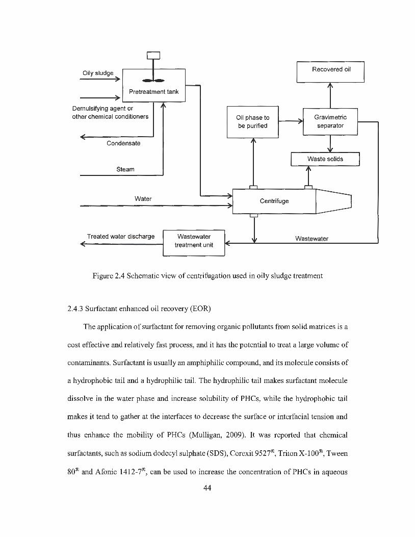
Oily sludge .... r -
Pretreatment tank -r
mulsifying agent or De oth er chemical conditioners
,J' .... Condensate
Steam
Water
Treated water discharge ,J' ....
JI\
Wastewater treatment unit
Recovered oil
'\
Oil phase to - Gravimetric be purified
, separator
'\
I Waste solids
'I\
r-, r, -, Centrifuge .... ,
L,..J
,J' w Wastewater ....
Figure 2.4 Schematic view of centrifugation used in oily sludge treatment
2.4.3 Surfactant enhanced oil recovery (EOR)
The application of surfactant for removing organic pollutants from solid matrices is a
cost effective and relatively fast process, and it has the potential to treat a large volume of
contaminants. Surfactant is usually an amphiphilic compound, and its molecule consists of
a hydrophobic tail and a hydrophilic tail. The hydrophilic tail makes surfactant molecule
dissolve in the water phase and increase solubility of PH Cs, while the hydrophobic tail
makes it tend to gather at the interfaces to decrease the surface or interfacial tension and
thus enhance the mobility of PHCs (Mulligan, 2009). It was reported that chemical
surfactants, such as sodium dodecyl sulphate (SDS), Corexit 9527®, Triton X-100®, Tween
80® and Afonic 1412-7®, can be used to increase the concentration of PH Cs in aqueous
44
I
phase (Christofi and Ivshina, 2002; Grasso et al., 2001; Cuypers et al., 2002; Prak and
Pritchard, 2002). Abdel-Azim et al. (2011) used three sets of surfactant (nonyl phenol
ethoxylates) based demulsifier mixture to break down petroleum sludge emulsion, and they
found that more than 80% of water can be separated from oily sludge. Similar results can
be found in Dantas et al. (200l)'s research. However, using chemical surfactants can be
associated with a range of problems such as environmental toxicity and resistance to
biodegradation (Christofi and Ivshina, 2002; Mulligan et al., 2001; Whang et al., 2008;
Cort et al., 2002). As compared to chemical surfactant, bio-surfactant has received
increasing attention since it exhibits greater environmental compatibility, more diversity,
better surface activity, lower toxicity, higher emulsification ability, higher selectivity, and
higher biodegradability (Syal and Ramamurthy, 2003; Urum et al., 2004; Ron and
Rosenberg, 2002; Mulligan, 2005; Pekdemir et al., 2005; Chin et al., 2009) . For instance,
Lima et al. (2011) compared the toxicity of five bio-surfactants and one chemical
surfactant called SDS to petroleum degrading microorganisms, and their results showed
that bio-surfactants had a significantly lower toxicity than SDS. Edwards et al. (2003) also
found that the toxicity of bio-surfactants to estuarine invertebrate species were much lower
than that of chemical surfactants.
Bio-surfactants are produced by yeast or bacterial from various substrates including
sugars, oils, alkanes and wastes. They can be grouped into five categories, including (1)
glycolipids, (2) lipopeptides, (3) phospholipids, fatty acids, and neutral lipids, polymetric
bio-surfactant, and particulate bio-surfactant (Mulligan, 2009). Most of the bio-surfactants
are either anionic or neutral, and only a few are cationic such as those containing amine
groups. Their structures include amphiphilic molecules with a hydrophobic moiety (i.e.
fatty acid) and a hydrophilic moiety ( e.g., carbohydrate, carboxylic acid, phosphate, amino
45
acid, cyclic peptide or alcohol) (Mulligan, 2005). A very wide spectrum of microbial
species can be used to produce bio-surfactants, and three groups of bio-surfactants have
been extensively studied, including (1) rhamnolipids (i.e. a type of glycolipids) produced
from Pseudomonas aeruginosa, (2) sorphorolipids (i.e. a type of glycolipids) produced
from Candida bombicola, and (3) surfactins (i.e. a type of Lipopeptides) produced from
Bacillus subtilis (Abalos et al., 2001; Noordman et al., 2002; Rahman et al., 2002; Straube
et al., 2003; Olivera et al., 2000; Makkar and Rockne, 2003). Various laboratory- and field-
scale studies have been conducted to use bio-surfactants in oily sludge treatment. For
example, Lima et al. (2011) isolated five bacterial strains for bio-surfactant production,
and they found that bio-surfactants produced by Dietzia maris sp., Pseudomonas
aeruginosa, and Bacillus sp. respectively recovered up to 95, 93 and 88% of the total oily
sludge as oil, but only 2% of the oil present in oily sludge was recovered when not using
bio-surfactant. Yan et al. (2012) proved the promising oil recovery performance of bio-
surfactant produced by Pseudomonas aeruginosa, and an oil recovery rate of up to 91.5%
was obtained when using bio-surfactant and centrifugation for oil separation from refinery
oily sludge. Long et al. (2013) also applied rhamnolipid to a pilot-scale (100 L) waste crude
oil treatment, and their results indicated that rharnnolipid could recover over 98% of crude
oil from the wastes, while the recovered oil contained less than 0.3% of water. In general,
surfactant enhanced oil recovery method is a simple but a relatively fast and effective
process, and it has a potential to treat a large volume of oily sludge. In spite of the
successful application of surfactants, several factors should be taken into account when
selecting surfactants for oil recovery, including effectiveness, cost, public and regulatory
acceptance, biodegradability, degradation products, toxicity, and ability to recycle. In
particular, the costs of producing bio-surfactants may limit their commercial applications.
46
The related costs can be reduced by improving yields, recovery, and using inexpensive or
waste substrates (Calvo et al., 2009).
2.4.4 Freeze/thaw treatment
One important process of oil recovery from oily sludge is to remove water from a
W/0 emulsion by separating oil and water into two phases, and this process is called
demulsification. Freeze/thaw treatment used for sludge dewatering in cold regions has
been reported as an effective demulsification method (Chen and He, 2003; Jean and Lee,
1999; Lin et al., 2007). As shown in Figures 2.5, two different mechanisms are responsible
for the demulsification. The first one occurs when water phase in emulsion becomes frozen
ahead of oil phase. The volume expansion of frozen water droplets leads to their
coalescence and cause the inner disarrangement of emulsion, and the oil phase is gradually
frozen with temperature dropping (Figure 2.5b ). During the thawing process, the oil phase
coalesces as a result of interfacial tension, and the oil-water mixture can thus be
delaminated into two bulk phases driven by gravitational force (Figure 2.5f) (Lin et al.,
2008). The second mechanism occurs when oil phase becomes frozen ahead of water phase.
This would form a solid cage that encapsulates water droplets during the freezing process
(Figure 2.5c). These water droplets are gradually frozen with temperature dropping, and
the volume expansion of frozen droplets breaks the oil cage. This could produce fine
crevices that allow the unfrozen water droplets to permeate and contact with each other,
forming a large network of micro-channels (Figure 2.5d). During the thawing process, this
network fuses with water droplet coalescence that leads to phase inversion (Figure 2.5e),
and such unstable oil-water mixture can then be delaminated into bulk phases driven by
gravitational force (Figure 2.5f) (Lin et al., 2008).
47
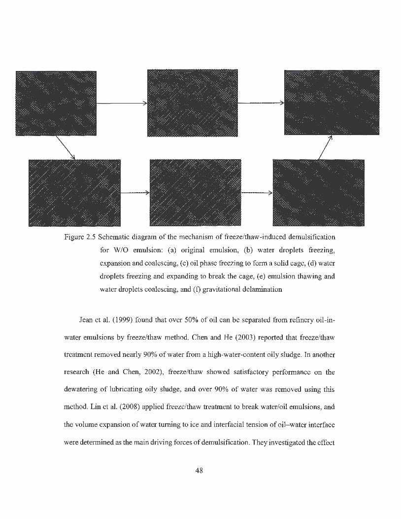
Figure 2.5 Schematic diagram of the mechanism of freeze/thaw-induced demulsification
for W/0 emulsion: (a) original emulsion, (b) water droplets freezing,
expansion and coalescing, ( c) oil phase freezing to form a solid cage, ( d) water
droplets freezing and expanding to break the cage, ( e) emulsion thawing and
water droplets coalescing, and ( f) gravitational de lamination
Jean et al. (1999) found that over 50% of oil can be separated from refinery oil-in-
water emulsions by freeze/thaw method. Chen and He (2003) reported that freeze/thaw
treatment removed nearly 90% of water from a high-water-content oily sludge. In another
research (He and Chen, 2002), freeze/thaw showed satisfactory performance on the
dewatering of lubricating oily sludge, and over 90% of water was removed using this
method. Lin et al. (2008) applied freeze/thaw treatment to break water/oil emulsions, and
the volume expansion of water turning to ice and interfacial tension of oil-water interface
were determined as the main driving forces of demulsification. They investigated the effect
48

of four different freezing methods (i.e. freezing in a refrigerator, cryogenic bath, dry ice
and liquid nitrogen), and found that the best freezing method was freezing in cryogenic or
dry ice, with over 70% dehydration efficiency being achieved for the emulsions containing
60% of water. Zhang et al. (2012) found that freeze/thaw worked effectively for oil
recovery from refinery sludge with an oil recovery rate of 65.7%. In general, the
performance of freeze/thaw on demuslification can be affected by a number of factors,
such as freezing and thawing temperatures, treatment duration, water content, salinity of
aqueous phase, presence of surfactants, and solid contents in emulsion (Lin et al., 2007;
Zhang et al., 2012). For example, Chun et al. (2004) found that the dewatering rate at -
40 °C was obviously higher than that at -20 °C, and the lower thawing temperature was
also beneficial to dewatering process. At high thawing temperature, the frozen sludge
could be melted rapidly which may break down the aggregated floes of oil/solids, thus
leading to poor dewaterability. Yang et al. (2009) compared the effect of three thawing
approaches on W /0 demulsification, and they found that rapid thawing (i.e. microwave
heating) could significantly enhance the water-oil separation efficiency, with more than
90% (v/v) of emulsion being separated. Similar results can be found in Rajakovic and Skala
(2006). Oh and Deo (2011) also proved that water content can affect oil recovery, with
higher yield stresses being observed in W/0 emulsion with lower water content. In
summary, freeze/thaw treatment is a promising method for dewatering and oil recovery
from oily sludge. However, its industrial application should consider the required freezing
time and related costs. Chun et al. (2004) suggested that 8 h was almost sufficient for
freezing at -20 °C. In addition, freezing could be a relatively slow process that requires
intensive energy and high cost (Jean and Lee, 1999). Thus, the application of freeze/thaw
49
treatment for oil recovery from oily sludge might be more promising for cold regions
where natural freezing is possible.
2.4.5 Pyrolysis treatment
Pyrolysis is the thermal decomposition of organic materials at elevated temperatures
(500-1000 °C) in an inert environment. It is different from gasification which transforms
organic materials to combustible gas or syngas with the existence of 20-40% of oxygen.
The pyrolysis process produces hydrocarbons with lower molecular weight in
condensation (i.e. liquid) and/or non-condensable gases. It also generates a solid product
called char (Fonts et al. , 2012). Depending on the operational conditions, the main product
of pyrolysis can be either char, liquid, or gas, and they may have a more elevated heating
value than the raw oily sludge (Zhang et al. , 2005). For example, the major product of fast
pyrolysis treatment (i.e. a pyrolysis process that rapidly heats feedstock to a controlled
temperature and then very quickly cools the volatile products formed in the reactor) can
be a liquid (i.e. pyrolysis oil), which could be used as a fuel or a source of other valuable
chemical products (Liu et al. , 2011; Bridgwater et al. , 1999). Several research studies have
been reported to use pyrolysis for fuel recovery from oily sludge. Shen and Zhang (2003)
observed that oil yield increased initially with pyrolysis temperature with a maximum oil
yield (30 wt.% of the feed oily sludge) occurring at 525 °C, but decreased when the
temperature was above 525 °C due to secondary decomposition reactions which could
break the oil into lighter and gaseous hydrocarbons. Liu et al. (2009) found that about 80%
of total organic carbon content (TOC) in oily sludge could be converted into usable
hydrocarbons when using a pyrolysis process, with a significant hydrocarbon yield
occurring in the temperature range of 327-450 °C. Schmidt and Kaminsky (2001) found
50

that the separation of oil from oily sludge occurred from 460 to 650 °C, and 70 to 84% of
the oil could be separated from sludge by a fluidized bed reactor. Chang et al. (2000)
applied the pyrolysis process to treat oily sludge, and they observed a maximum production
rate of hydrocarbons (mainly low-molecular-weight paraffins and olefins, 51.61 wt% of
PH Cs) at 440 °C, and the distillation characteristics of liquid product from pyrolysis were
close to that of diesel oil. Their results also indicated that the major gaseous products from
pyrolysis excluding N2 are CO2 (50.88 wt%), hydrocarbons (25.23 wt%), H20 (17.78 wt%),
and CO (6.11 wt%) (Chang et al., 2000). Karayildirim et al. (2006) illustrated that the main
decomposition of oily sludge occurred in the temperature range of 100-350 °C, while the
inorganic materials started decomposition when the temperature rose to 400 °C, and the
carbonaceous residues accounted for 38 wt% of the original sludge at the final pyrolysis
temperature of 900 °C. Wang et al. (2007) found that pyrolysis of oily sludge started at a
low temperature of 200 °C, and the maximum hydrocarbon production occurred in the
range of 350-500 °C, with improved oil yield and quality being observed by maintaining
temperature at 400 °C for 20 min.
Pyrolysis can be affected by a number of factors, such as temperature, heating rate,
characteristic of oily sludge and chemical additives. Punnaruttanakun et al. (2003)
investigated the influence of different heating rate (i.e. 5, 10 and 20 °C/min) on the
pyrolysis of API separator sludge, and they found a lower pyrolysis rate at a heating rate
of 20 °C/min than those at 5 and 10 °C/min, but the heating rate did not affect the amount
of solid products. Shie et al. (2003) found that chemical additives (such as sodium and
potassium compounds) in the pyrolysis process could enhance the reaction rate within a
pyrolysis temperature range of 377-437 °C, and the highest fuel yield was obtained as
73.13 wt.% with the addition of KCl, while the maximum improvement effect on the
51
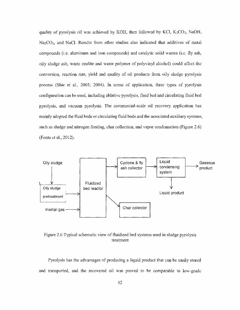
quality of pyrolysis oil was achieved by KOH, then followed by KCl, K2C03, NaOH,
Na2C03, and NaCl. Results from other studies also indicated that additives of metal
compounds (i.e. aluminum and iron compounds) and catalytic solid wastes (i.e. fly ash,
oily sludge ash, waste zeolite and waste polymer of polyvinyl alcohol) could affect the
conversion, reaction rate, yield and quality of oil products from oily sludge pyrolysis
process (Shie et al., 2003; 2004). In terms of application, three types of pyrolysis
configuration can be used, including ablative pyrolysis, fluid bed and circulating fluid bed
pyrolysis, and vacuum pyrolysis. The commercial-scale oil recovery application has
mainly adopted the fluid beds or circulating fluid beds and the associated auxiliary systems,
such as sludge and nitrogen feeding, char collection, and vapor condensation (Figure 2.6)
(Fonts et al., 2012).
I
Oily sludge Cyclone & fly Liquid .... ----? '
l ., ash collector condensing .,
system
Fluidized Oily sludge bed reactor w
... Liquid product pretreatment
,
~ Char collector Inertial gas .... .,
Figure 2.6 Typical schematic view of fluidized bed systems used in sludge pyrolysis treatment
Gaseous product
Pyrolysis has the advantages of producing a liquid product that can be easily stored
and transported, and the recovered oil was proved to be comparable to low-grade
52
petroleum distillates from commercial refineries and could be directly used in diesel
fuelled engines (Czernik and Bridgewater, 2004; Chiaramoni et al. , 2007) . As compared
to the incineration process, pyrolysis of oily sludge generates a lower emission ofNOx and
SOx, and it also enables heavy metals in oily sludge to be concentrated in the final solid
product (i.e. char) (Shen and Zhang, 2003). The char usually accounts for 30 to 50 wt% of
the original oily sludge, and it can be applied as an adsorbent for the removal of different
pollutants such as H2S or NOx in gaseous streams (Fonts et al., 2012). It can also be used
as a soil conditioner to increase the nutrient availability for plants (Lehmann and Rondon,
2006). The metals enriched in solid char can be more resistant to leaching than those
concentrated in the ash obtained from incineration (Mohan et al. , 2007). In spite of these
advantages, the large-scale implementation of pyrolysis could be restricted by the low
economic value of liquid products and the relatively complex processing equipments
(Bridle and Pritchard, 2004; Lim and Parker, 2008). The high operational cost is mainly
due to the large amount of external energy required for the endothermic reaction to take
place (Fonts et al. , 2012). In addition, oily sludge usually contains a relatively high water
content, and thus the dewatering of oily sludge before pyrolysis treatment may
significantly increase the overall cost of pyrolysis (Bridle and Unkovich, 2002). Additional
concern may include that P AHs, the well-known highly carcinogenic substances, could be
existed as a large portion in the liquid products of sludge pyrolysis (Kwah et al. , 2006).
2.4.6 Microwave irradiation
The microwave frequency ranges from 300 MHz to 300 GHz, but the industrial
application is usually performed at a frequency either close to 900 MHz or near 2450 MHz
(Appleton et al. , 2005). Microwave energy can directly penetrate the material through
53
molecular interaction with the electromagnetic field, and provide a quick heating process
at improved heating efficiencies as compared with conventional techniques. Such heating
effect can be used for the demulsification of W/0 emulsion by rapidly increasing the
temperature of emulsions, leading to the reduction of viscosity which could accelerate the
settlement of water droplets in emulsion (Tan et al. , 2007). The rapid temperature increase
can also break heavy hydrocarbons into lighter ones. For materials with low dielectric loss,
microwave can pass through them with little energy absorption. For materials with high
dielectric loss, microwave energy can be absorbed based on the electric field strength and
the dielectric loss factor. When using microwave for treating a mixture of materials with
different dielectric properties, a selective heating could occur (Chan and Chen, 2002;
Shang et al., 2006). For W/0 emulsion such as oily sludge, the inner phase is water with a
relatively higher dielectric loss, and it can absorb more microwave energy than oil. Such
energy absorption could result in the expansion of water and press the water-oil interfacial
film to become thinner, which could facilitate water/oil separation (Tan et al., 2006).
Moreover, microwave irradiation could lead to molecular rotation by rearranging the
electrical charges surrounding water molecules. This could destroy the electric double
layers at the oil/water interface, resulting in the reduction of zeta potential. Under reduced
zeta potential, water and oil molecules can move more freely in the emulsion so that the
water or oil droplets can collide with each other to form coalescence (Tan et al., 2006).
The above mechanisms can lead to the separation of an emulsion (Kuo and Lee, 2010).
Several laboratory- and field-scale studies have demonstrated the benefits of using
microwave irradiation for W/0 emulsion treatment. Xia et al. (2003) observed a nearly
100% of demulsification efficiency within a very short time by using microwave radiation
for treating W/0 emulsions, which is much higher than that when using conventional
54
heating approaches. Fang and Lai (1995) applied microwave irradiation for a field test to
demulsify 188 barrels ofW/0 emulsion in tanks, and their results showed that the emulsion
was separated into 146 barrels of oil and 42 barrels of water, while the water separation
efficiency from emulsions was higher than that when using conventional heating. They
also illustrated that microwave irradiation could have particular effect on the partial
removal of polar compounds (Fang and Lai, 1995).
The performance of microwave irradiation on oily sludge demulsification can be
affected by many factors such as microwave power, microwave duration, surfactant, pH,
salt, and other properties of oily sludge such as water-oil ratio (Fortuny et al., 2007). The
increase of pH could decrease the stability of sludge W /0 emulsion due to the increase in
hydrophilicity (Fortuny et al., 2007). On the other hand, the salt-assisted microwave
irradiation has been found to be effective due to increased conductivity of water phase that
could accelerate the heating rate (Xia et al., 2004). For example, Chan and Chen (2002)
found that electrolyte could lower the Zeta potential of oil droplets and result in the
destabilization of W /0 emulsions, and they observed that the demulsification rate
increased with electrolyte concentration (NaCl, KCl, NaN03, and Na2S04) in the range of
dilute solutions (< 0.5 M) when using microwave irradiation. The optimum microwave
irradiation power and treatment time were suggested to be 420 Wand 12 seconds in their
research (Chan and Chen, 2002). Fortuny et al. (2007) investigated the demulsification
effect of salt (Na Cl) on a crude oil emulsion by microwave irradiation, and they found that
the dissolved salts significantly increased the heating efficiency and destabilization of
emulsions. Tan et al. (2007) found that the performance of microwave treatment on W/0
emulsions could be improved by the addition of chemical demulsifiers, and a satisfactory
water-oil separation efficiency (95v/v%) was achieved by adding 50 ppm of demulsifier
55
when using microwave irradiation (700 W, 2450 MHz). Abdulbari et al. (2011) combined
microwave heating (900 W, 2450 MHz) with synthetic surfactants (i.e. Triton X-100, low-
sulfur waxy residue, sorbitan monooleate, and SDS) to separate water from petroleum
emulsions, and their results indicated that over 90% of water can be separated. In general,
as compared to other heating methods, microwave irradiation can more rapidly raise the
energy of molecules inside the medium, leading to higher reaction rates and superheating
within several minutes (Robinson et al., 2008). The short heating time makes microwave
irradiation a high energy-efficient and easy-to-control approach for breaking emulsions. In
addition to its high demulsification efficiency, the low temperature of reactor wall during
the direct heating inside the bulk medium caused by microwave irradiation could lead to
an extended aromatization reaction. This could result in an increased yield oflight aromatic
compounds. These light compounds can have a much lower toxicity as compared to P AHs
with high molecular weight in the liquid products generated during the pyrolysis process
(Dominguez et al., 2005). However, the application of microwave irradiation to industrial-
scale oily sludge treatment is limited due to the specific equipment required and possible
high operating costs.
2.4. 7 Electrokinetic method
Electrokinetic process utilizes a low-intensity direct current across an electrode pair
on each side of a porous medium, causing the electro osmosis of liquid phase, migration
of ions and electrophoresis of charged particles in a colloidal system to the respective
electrode (Virkutyte et al. , 2002; Yang et al. , 2005). The separation of different phases
(water, oil, and solids) from oily sludge using electrokinetic process can be based on three
main mechanisms. Firstly, colloidal aggregates in oily sludge can be broken under the
56
influence of an electrical field, leading to the movement of colloidal particles of oily sludge
and solid phase towards the anode area as a result of electrophoresis, and the movement of
the separated liquid phase (water and oil) towards the cathode area as a result of electro-
osmosis (Yang et al., 2005). As mentioned before, oily sludge is a W /0 emulsion stabilized
by several kinds of emulsifiers such as asphaltenes, resins, organic acids, and finely
divided solids. These emulsifiers usually occur as a film on the surface of dispersed water
droplets, and the fine particles can be adsorbed at the water droplet surface and act as a
barrier to prevent droplet coalescence (Ali and Alqam, 2000). The separation of colloidal
particles and fine solids from W /0 emulsion could remove such barrier and thus accelerate
the coalescence of water droplets in continuous oil phase. Secondly, following this process,
the electro-coagulation of the separated solid phase could occur near the anode area,
leading to increased solid phase and sediments concentration. Lastly, the separated liquid
phase (water and oil, without colloid particles and fine solids) can produce an unstable
secondary oil-in-water emulsion which could be gradually electro-coalesced near the
cathode area through charging and agglomeration of droplets, thus forming two separated
phases of water and oil (Elektorowicz et al., 2006).
The electrokinetic treatment performance can be affected by several factors such as
resistance, pH, electrical potential, and spacing between electrodes. This process may be
improved through the use of surfactants or reagents to increase the contaminant removal
rates at the electrodes (Electorowicz and Hatim, 2000). Elektorowicz and Habibi (2005)
applied electrokinetic process to treat oily sludge, and they found that this process could
reduce the amount of water by nearly 63% and light hydrocarbon content by about 43%,
and the light hydrocarbon content was removed by 50% when combining electrokinetic
treatment with surfactant. Yang et al. (2005) conducted an oily sludge dewatering study
57
using electrokinetic treatment, and their results showed that the water removal efficiency
reached to 56.3% at a 4 cm electrode spacing and an electric potential of 30 V, while the
solids content at the anode area increased from 5 to 14.1 %. A larger-scale experimental
study (i.e. a capacity of 4 L) revealed that more than 40% of water was removed and a very
efficient oil separation from oily sludge was achieved using electrokinetic process at 60 V
with an initial spacing of 22 cm (Ali and Alqam, 2000), and the temperature in the system
was observed to increase significantly in a short time due to the application of high electric
current. In general, the application of electrokinetic process for oil recovery from oily
sludge requires less amount of energy than other oil recovery methods such as
centrifugation and pyrolysis. However, most of the electrokinetic studies on oily sludge
have been conducted at the laboratory level, and the performance and costs at a large scale
still need further investigation. It is expected that using oily sludge storage pools as the
electrokinetic cell at the field scale could considerably reduce the treatment cost
(Elektorowicz et al., 2006).
2.4.8 Ultrasonic irradiation
Ultrasonic irradiation has proved to be effective for removing adsorbed materials
from solid particles, separating solid/liquid in high-concentration suspensions, and
decreasing the stability ofW/0 emulsion (Li et al., 2013; Song et al., 2012; Kim and Qang,
2003; Ye et al., 2008). When ultrasonic wave propagates in the treatment medium, it
generates compressions and rarefactions. The compression cycle exerts a positive pressure
on the medium by pushing molecules together. The rarefaction cycle exerts a negative
pressure by pulling molecules from each other, and microbubbles can be generated and
grow due to such negative pressure. When these microbubbles grow to an unstable
58
dimension, they can collapse violently and generate shock waves, resulting in very high
temperature and pressure in a few microseconds (Pilli et al. , 2011). Such cavitation
phenomenon can increase the temperature of the emulsion system and decrease its
viscosity, increase the mass transfer of liquid phase, and thus lead to destabilization of
W/0 emulsion (Chung and Kamon, 2005). Other studies suggested that under the influence
of ultrasonic irradiation, smaller droplets in emulsion can move faster than the larger ones,
and this can increase their collision frequency to form aggregates and coalescence of
droplets, which then promotes the separation of water/oil phases (Yang et al. , 2009;
Gholam and Dariush, 2013). Ultrasonic irradiation can not only clean the surface of solid
particles but also penetrate into different regions of a multiphase system that are
inaccessible when using other separation methods (Swamy and Narayana, 2001). This
mechanism is called ultrasonic leaching which enables solvents or leaching reagents to
more readily enter the interior of solids pores, and increases the mass transfer of
contaminants through the solids matrix (Feng and Aldrich, 2000). A number of studies
have been conducted to investigate the efficiency of ultrasonic irradiation for oil recovery
from oily sludge. Xu et al. (2009) applied ultrasonic cavitation with a frequency of28 kHz
in an ultrasonic cleaning tank to strip oil constituents from the surface of solid particles in
oily sludge, and an overall oil separation rate of 55.6% was obtained. They also found that
the optimal temperature, acoustic pressure, and ultrasonic power for oil recovery from
sludge were 40 °C, 0.10 MPa, and 28 kHz, respectively, while both too high or too low
ultrasonic energy input could inhibit oil recovery process since high ultrasonic energy
input can prevent oil droplets from merging and low ultrasonic energy input makes it
difficult to detach oil from solid particles. Zhang et al. (2012) reported an oil recovery rate
59
of up to 80% from oily sludge-water matrix (sludge/water ratio of 1:2) after 10 min of
ultrasonic treatment using a 20 kHz ultrasonic probe system at a power of 66 W.
In general, the performance of oil recovery from oily sludge using ultrasonic
treatment can be affected by a variety of factors, such as ultrasonic frequency, sonication
power and intensity, water content in emulsion, temperature, ultrasonic treatment duration,
solid particle size, initial PHCs concentration, salinity, and presence of surfactant (Kim
and Wang, 2003; Feng and Aldrich, 2000; Na et al. , 2007) . For example, Xu et al. (2009)
found that lower ultrasonic frequency is more favorable for oily sludge treatment since
cavitation is more difficult to occur under high frequency ultrasound than that under low
frequency ultrasound, and they also indicated that too high or too low temperature is not
suitable for oily sludge treatment by ultrasound. In the research by Jin et al. (2012), a high
oil recovery rate (above 95%) was achieved when the ultrasonic treatment parameters were
28 kHz, 15 min, 400 Wand 60 °C, respectively, and no further enhancement of oil recovery
was observed when the ultrasonic power and treatment duration increased beyond 400 W
and 15 min. Overall, ultrasonic irradiation is a "green" treatment method which can process
oily sludge within a relatively short time. In spite of its high efficiency of oil recovery and
no secondary pollution, the application of ultrasonic irradiation to field-scale oil recovery
from sludge has rarely been reported, while the most commonly used laboratory ultrasonic
irradiation system was the ultrasonic probe system which can only be effective when
treating a small volume of oily sludge. The utilization of large ultrasonic cleaning tank
could be more promising in terms of treating a large amount of oily sludge, but its oil
recovery performance might be compromised due to the resulted low ultrasonic intensity
(Canselier et al. , 2007). The high cost of equipment and maintenance could also inhibit the
industrial application of this technology.
60
2.4.9 Froth flotation
Froth flotation is a surface chemistry-based unit operation for separating fine solid
particles from an aqueous suspension. It involves the capture of oil droplets or small solids
by air bubbles in an aqueous slurry, followed by their levitation and collection in a froth
layer (Urbina, 2003). Froth flotation has been successfully used to treat oily wastewater
from refineries, and its utilization for oily sludge treatment has recently received research
attentions (Ramaswamy et al. , 2007). Figure 2.7 presents a schematic overview of this
process. Oily sludge is firstly mixed with a given amount of water to form a sludge slurry.
Air injection then generates fine air bubbles which approach oil droplets in the slurry
mixture, and the water film between oil and air bubble can get thinning to reach a critical
thickness, causing the rupture of water film and the spreading of oil to air bubbles. Lastly,
the conglomerate of oil droplets with air bubbles can quickly rise to the top of water/oil
mixture, and the accumulated oil can be skimmed off and collected for further purification
(Moosai and Dawe, 2003). Ramaswamy et al. (2007) applied froth flotation treatment for
oil-water separation from oily sludge, and they observed an oil recovery of up to 55% at
the optimal flotation conditions. Addition of surfactants and extraction solvent could
enhance the oil recovery performance of flotation. Al-Otoom et al. (2010) applied a
modified fluidized flotation process for bitumen recovery from tar sand, and the maximum
bitumen recovery could reach 86 wt% when 0.35 wt% light cycle oil was added as an
extraction solvent at 80 °C. Stasiuk et al. (2001) found that the addition of surfactants such
as Tween 80 or Alcopol O during the froth flotation process significantly reduced water
contents (i.e. 10 v/v%) in the recovered oil.
61

• D • • • • • • • t Water phase
• C ··viu,. Feed water
Figure 2.7 Schematic view of froth flotation in oil/water separation process (A: Air
control valve; B: Motor; C: Stirrer; D: Skimmed oil collector)
In general, oil recovery performance using froth flotation can be affected by many
factors, such as oily sludge properties (i.e. viscosity, solid content and density), pH, salinity,
temperature, size of air bubble, presence of surfactant, and flotation duration (Al-Shamrani
et al., 2002; Faksness et al., 2004). Ramaswamy et al. (2007) reported that the oil recovery
rate increased with the duration of flotation but approached its maximum after 12 min of
treatment, and they also found that surfactant had significant influence on the oil recovery
process. Higher temperature could also enhance the oil recovery via flotation since
decreased sludge viscosity would facilitate oil separation and the subsequent flotation (Al-
Otoom et al., 2010). Froth flotation is a simple and less expensive approach for oily sludge
treatment, but it is usually effective when treating sludge with relatively low viscosity. It
has limited effect on the desorption of oil from solid matrix, and the oil constituents in
skimmed oil/solids mixture still need to be further purified. The recovered oil could also
contain relatively high moisture. Consequently, a number of limitations still exist when
62
Oil film

applying it to field-scale oily sludge treatment. Oily sludge needs to be pretreated to reduce
its viscosity and remove the coarse solid particles. Moreover, the froth flotation requires a
large volume of water when treating oily sludge with low moisture and high viscosity, and
thus oily wastewater treatment problem can be generated.
2.5 Oily Sludge Disposal Methods
In addition to oil recovery, a number of technologies are available for the disposal of
oily sludge, including incineration, stabilization/solidification, oxidation, and
biodegradation.
2. 5 .1 Incineration
Incineration is a process of complete combustion of oily wastes in the presence of
excess air and auxiliary fuels, and it is widely adopted in large refineries for sludge
treatment. Rotary kiln and fluidized bed incinerator are the most commonly used
incinerators. In rotary kiln incinerator, the combustion temperature is in the range of 980-
1200 °C and the residence time is around 30 min. In fluidized bed incinerator, the
combustion temperature can be in the range of 730-760 °C, and the residence time can be
in order of days (Scale and Chirone, 2004 ). Fluidized bed incinerator is especially effective
when treating low-quality sludge due to its fuel flexibility, high mixing efficiency, high
combustion efficiency and relatively low pollutant emissions (Zhou et al., 2009). The
incineration performance can be affected by a variety of factors, including combustion
condition, residence time, temperature, feedstock quality, presence of auxiliary fuels, and
waste feed rates. Liu et al. (2009) investigated the incineration of oily sludge by the
addition of an auxiliary fuel consisting of coal-water slurry (CSW) in a fluidized bed boiler,
63
and they found that the temperature of combustion could be stabilized by controlling the
CSW feeding rate, with a combustion efficiency of 92.6% being reached. They also found
that the gaseous emission from incineration and heavy metals in ash residues could meet
the corresponding environmental regulations. Wang et al. (2012) examined the
incineration of a petroleum coke-sludge slurry (PCSS) which was obtained by blending
oily sludge with a petroleum coke-water slurry (PCWS), and they found that the PCSS fuel
exhibited low viscosity and satisfactory stability for combustion process, but the
combustion efficiency, gaseous emission, and heavy metals in ash residues were not
investigated in their study. Sankaran et al. (1998) investigated the direct combustion of
three types of oily sludge in a fluidized bed incinerator without auxiliary fuels, and a high
combustion efficiency of 98-99% was observed for sludge with low water content, but the
combustion was difficult to occur for sludge with a relatively high water content (i.e. >
51 %). They also found that oily sludge was too viscous to flow as the feedstock, and a pre-
treatment such as heating was required to reduce the viscosity before incineration
(Sankaran and Pandey, 1998).
Through combustion in an incinerator, oily sludge can provide a valuable source of
energy, which can be used to drive steam turbines and as a heat source in a waste oil
reclamation factory. Moreover, a significant reduction in the volume of waste can be
achieved after incineration treatment. Although the oily sludge incineration has been
practised in a few developed countries (Naranbhai and Sanjay, 1999), it suffers from a
number of limitations. Oily sludge with high moisture needs to be pre-treated to improve
its fuel efficiency by lowering the excessive water content (Al-Futaisi et al. , 2007).
Auxiliary fuel is usually required to maintain a constant combustion temperature (Li et al. ,
1995; Bhattacharyya and Shekdar, 2003). In addition, fugitive emission of pollutants (e.g. ,
64
low molecular P AHs) from incineration and incomplete combustion could cause
atmospheric pollution problem (Li et al., 1995). Moreover, ash residue, scrubber water,
and scrubber sludge generated during the incineration process are hazardous and need
further treatment. In general, the oily sludge contains high concentration of hazardous
constituents that are resistant to combustion, and the incineration requires high capital and
operating costs, with a cost of more than $800 per ton of oily sludge incineration was
reported (Shiva, 2004).
2.5.2 Stabilization/solidification
Stabilization/solidification (S/S) is a quick and inexpensive waste treatment technique
aimed at immobilizing contaminants by converting them into a less soluble or a less toxic
form (i.e. stabilization), and encapsulating them by the creation of a durable matrix with
high structural integrity (i.e. solidification) (Malviya and Chaudhary, 2006). The use of
this disposal method for inorganic wastes has been widely reported (Leonard and
Stegemann, 2010). However, S/S was considered less compatible with organic wastes
since organic compounds may inhibit cement-based binder hydration and are generally not
chemically bound in the binder hydration products (Malviya and Chaudhary, 2006). As a
result, immobilization of organic contaminants depends mainly on physical entrapment in
the binder matrix and sorption onto the surface of binder hydration products. There is a
possibility of releasing undesirably high concentration of pollutants when exposed to
environmental leachants. Karamalidis and Voudrias (2007) studied the leaching behavior
of TPH, alkanes and P AHs from refinery oily sludge stabilized/solidified with Portland
cement, and their results showed that the waste was confined in the cement matrix by
macro-encapsulation, but they also reported that increased cement addition to oil refinery
65
sludge led to higher concentrations in leachates from batch extraction. Other leaching test
studies of oily sludge S/S treatment using Portland cement have shown relatively high
release of PAHs (Conner and Hoeffner, 1998) and methanol and 2-chloroaniline (Gussoni
et al., 2004). In general, a Portland cement only binder system is not effective for the
immobilization of several common organic contaminants. A possible method for
improving the effectiveness of S/S treatment for organic wastes is to use binders that
increase sorption of organic compounds ( e.g., combined use of cement and activated
carbon), thereby improving their immobilization and preventing their detrimental effects
on binder hydration. Leonard and Stegemann (2010) found that Portland cement with the
addition of high-carbon power plant fly ash (HCFA) significantly reduced the leaching of
PH Cs.
In addition to the immobilization of organic contaminants, an advantage of applying
S/S method is that some hazardous heavy metals in oily sludge can be immobilized into
the cement matrix. Karamalidis and Voudrias (2007) evaluated the leaching behavior of
heavy metals from stabilized/solidified refinery oily sludge and ash produced from oily
sludge incineration with Portland cement (OPC), and an immobilization of > 98% was
observed for metals of solidified ash at pH > 6 and of > 93% of solidified oily sludge at
pH > 7. They found that pH had the strongest influence on the immobilization of heavy
metals during the S/S process, and an extremely high Ni immobilization (> 98%) was
observed for solidified oily sludge samples at pH > 8, but the immobilization was very low
(47%) at pH of 2.5. Al-Futaisi et al. (2007) solidified tank bottom sludge mixtures using
three combinations of selected additives such as Portland cement (OPC), cement by-pass
dust (CBPD) and quarry fines (QF), and the toxicity characteristic leaching procedure
(TCLP) analyses results revealed that no extracts exceeded the regulated TCLP maximum
66

limits of metals. Although S/S technique has shown effectiveness on immobilizing
inorganic and organic contaminants in oily sludge, little is known from the current
literatures regarding the physical strength of S/S treated oily sludge and its cost for
handling a large volume of oily sludge. Further researches, including the use of other
binders such as pozzolanic substances ( e.g., fly ash) and other cement-like materials in the
S/S of oily sludge, are also worth to be conducted.
2.5.3 Oxidation treatment
Oxidation treatment has been used to degrade a range of organic contaminants
through chemical or other enhanced oxidation processes (Ferrarese et al., 2008). Chemical
oxidation involves introducing reactive chemicals into oily wastes to oxidize organic
compounds to carbon dioxide and water, or transform them to other nonhazardous
substances such as inorganic salts (Ferrarese et al., 2008). The oxidation can be brought
by Fenton ' s reagent, hypochlorite, ozone, ultrasonic irradiation, permanganate, and
persulfate, by generating a sufficient amount of radicals such as hydroxyl radicals (OH•)
which can quickly react with most organic and many inorganic compounds (Rivas, 2006).
Many studies have proven that chemical oxidation can effectively degrade PHCs and
P AHs in soils, and this method has recently been applied to oily sludge treatment. Mater
et al. (2006) found that a Fenton type reagent (i.e. 12 wt% of H202 and 10 mM of Fe2+) at
a low pH (i.e. pH= 3.0) can significantly reduce the concentrations of PAHs, phenols and
BTEXs in oily sludge contaminated soil. Ultrasonic irradiation has also recently been
investigated for its efficiency on oily sludge oxidation process. The sonication of water
can produce intermediate radicals such as hydrogen (H•), hydroxyl (OH•), hydroperoxyl
(H02•) and hydrogen peroxide (H202) with high oxidization power in and around the
67
cavitation bubbles (Mason, 2007). Through sonolysis reaction by these free radicals, long-
chain or aromatic petroleum hydrocarbons with complex structure and large molecular
weight can be broken into simple hydrocarbons which have higher solubility and
bioavailability. Ultrasound can be used to degrade many PHCs, such as chlorinated
aliphatic hydrocarbons (CAHs), aromatic compounds, polychlorinated biphenyls (PCBs),
poly aromatic hydrocarbons (PAHs), and various phenols (Adewuyi, 2001; Dewulf and
Langenhove, 2001; Collings et al., 2006; Lim et al., 2007). Zhang et al (2013) utilized a
combined process of ultrasonic and Fenton oxidation for the oily sludge treatment, and it
was found that ultrasonic irradiation could enhance the Fenton oxidation effect on oily
sludge degradation by improving the contact of hydroxyl radicals (OH•) with PHCs
compounds.
Other advanced oxidation methods such as supercritical water oxidation (SCWO),
wet air oxidation (W AO), and photocatalytic oxidation (PO) have been reported in recent
literatures of oily sludge treatment. SCWO method uses water above its critical point
(375 °C, 22.1 MPa) as a reaction medium where gases, oil and aromatics form a single
homogeneous phase, and the oxidation could proceed quickly and completely by
converting most H-C-N compounds to water, carbon dioxide, and molecular nitrogen
(Fujii et al., 2011). Cui et al. (2009) applied the SCWO method for oily sludge treatment,
and their results indicated that 92% of chemical oxygen demand (COD) in oily sludge was
removed after only 10 min of treatment. The W AO technology uses oxygen as the oxidant
under high temperature and high pressure to convert hazardous organic compounds to CO2,
H20 and other innocuous end products. Jing et al. (2011) found that the WAO process
could remove 88.4% of COD in oily sludge within 9 min of reaction at temperature of
330 °C and an 02 excess of 0.8, and the COD removal can be increased to 99.7% with the
68
addition of Ni2+ catalyst. Fe3+ catalyst can also improve the COD removal during oily
sludge treatment using W AO process. It was reported that a very promising COD removal
rate of 95.4% was achieved under the catalytic effect of Fe salt (i.e. 50 mg/L of Fe3+)
compared to that of 84.12% in the treatment without the addition of Fe3+ catalyst (Jin et
al., 2012).
Another enhanced oxidation treatment is the heterogeneous photocatalytic oxidation
which is based on the activation of the surface of a photo-conductor (e.g., titanium dioxide
in the Anatase form) by light (e.g., UV light or sunlight). The absorption of photons with
energy higher than the band gap of the photo-conductor produces pairs of conduction band
electrons ( e-) and valence band vacancies (h +). After this first step, the charge carriers either
recombine within the bulk of the material or migrate to the particle surface, where they can
react with adsorbed electron donors (D) and acceptors (A) species (Mazzarino and
Piccinini, 1999). The presence of oxygen and water is essential to the photocatalytic
process. Oxygen serves as the e- acceptor which can form the superoxide radical anion Oi"
•. The surface-bound water and the surface hydroxyl groups are oxidized by the vacancies
to form OH• radicals which are supposed to be the most active oxidizing species. da Rocha
et al. (2010) applied the heterogeneous photocatalytic oxidation (H202/UV/Ti02) for oily
sludge treatment, and they found that white light catalyzed oxidation was able to eliminate
100% of P AHs in sludge after 96 h of treatment. They also revealed that white light was
more effective than black light in terms of catalyzing oxidation on P AHs. However, the
effect of photocatalytic oxidation on other constituents such as asphaltenes and resins in
oily sludge was not investigated in their study. In general, oxidation requires a relatively
short treatment duration to degrade oily sludge, and it is relatively insensitive to external
disturbances ( e.g. , pollutant loading, temperature change, and the presence of biotoxic
69

substances, etc.). Its reaction products are usually more biodegradable than the raw waste
materials (Jin et al. , 2011). However, when treating a large volume of oily sludge, the
oxidation may require a large amount of chemical reagents. The advanced oxidation
methods such as W AO, SCWO and PO also require special equipments and considerable
energy inputs which could increase the treatment cost.
2.5.4 Bioremediation
Bioremediation is defined as the process of using micro-organisms to remove
environmental pollutants, and is commonly employed for the restoration of oil-polluted
environments through accelerating the microbial degradation of PHCs (Luquefio et al. ,
2011). The most intensively studied bioremediation approaches include land treatment,
biopile/composting, and bio-slurry treatment (Powell et al., 2007).
2. 5. 4.1 Land treatment
Land treatment involves the incorporation of wastes into soil and then the use of
various processes to degrade contaminants in that soil (Hejazi et al., 2003). Biological
activity usually accounts for most of the degradation of organic pollutants, while physical
and chemical removal mechanisms such as evaporation and photo-degradation may also
be important for some compounds. Landfarming is a widely employed land treatment
approach, and it spreads the well-mixed oily sludge and fresh soil on the ground surface
of a treatment site. The treatment efficiency can be improved by maintaining appropriate
sludge application rate, aeration, fertilization, moisture content, and pH to maintain
microbial density and enhance their activity in the sludge/soil mixture. Marin et al. (2005)
applied landfarming method to clean up oil refinery sludge in a semi-arid climate, and their
results showed that 80% of the PHCs were removed within 11 months of treatment, while
70
half of this removal occurred during the first three months. Admon et al. (2001) also
observed similar degradation pattern through experiments on the landfarming of refinery
oily sludge, and 70-90% of PH Cs degradation occurred within 2 months, while a relatively
high biodegradation activity was observed in the first 3 weeks of treatment. Hejazi and
Husain (2004) compared the influence of three operating parameters (i.e. tilling, addition
of water, and addition of nutrients) on a 12-month oily sludge land treatment under arid
conditions, and they found that tilling was the main parameter responsible for achieving
the highest PHCs removal rate of 76%. Mishra et al. (2001) combined bioaugmentation
(i.e. introducing extraneous bacterial consortium) and biostimulation (i.e. addition of
nutrients and water) for oily sludge decontamination, and their results indicated that up to
90.2% of TPH can be degraded in 120 days in the land block which had extraneous
bacterial consortium inoculum and nutrients enhancement, while only 16.8% ofTPH was
eliminated in the control land block.
As compared to other oily sludge disposal technologies, landfarming holds many
merits such as relatively low capital costs, simple operation, high potential for success, low
energy consumption, and the capability of treating a large volume of oily sludge (Hejazi
et al. , 2004). However, landfarming of oily sludge requires a large area of land, and is a
very time-consuming process (e.g. , usually 6 months to 2 years or even longer) since the
soil/sludge conditions favoured by biodegradation are largely uncontrolled, particularly for
recalcitrant and heavy PHC compounds. In addition, temperature can greatly affect the
contaminant biodegradation efficiency, and the performance of oily sludge landfarming in
cold regions can be compromised. Moreover, landfarming can bring various environmental
issues, such as the emission of volatile organic compounds (VOCs) and the risk of
groundwater pollution due to the migration of leachate that may contain PHCs, phenols
71
and heavy metals (Bhattacharyya and Shekdar, 2003). For example, Hejazi et al. (2004)
reported that weathering (i.e. evaporation) and not biodegradation was the overall
dominant degradation mechanism occurring in a landfarm under hot and arid climate
conditions. Results from a 12-month field study showed that up to 76% of oil and grease
in oily sludge has been evaporated as a result of weathering, while relatively long chain
alkanes such as C17 and C1 s were biodegraded in the landfarm (Hejazi and Husain, 2004).
Another advanced land treatment approach is secure landfill after oily sludge dewatering.
This technology isolates sludge wastes from air and water through the use of thick layers
of impermeable clay and synthetic liner, and it also employs a leachate collection system
above the bottom liner (Moses et al. , 2003 ; Butt et al., 2008). Secure landfill is popular in
developed countries such as the USA, UK, Canada, and Germany, and it can greatly
address the environmental problems associated with landfarming, but its treatment cost is
much higher (Bhattacharyya and Shekdar, 2003).
2.5.4.2 Biopile/composting
Biopile/composting of petroleum wastes has received increased attention as a
substitute technology for landfarming which often requires a large land area. Biopile refers
to the turning of waste materials into piles or windrows usually to a height of 2-4 m for
degradation by indigenous or extraneous micro-organisms. The piles may be static with
installed aeration piping, or turned and mixed by special devices. The bio-treatment
efficiency can be improved with moisture adjustment, air blowing, and the addition of
bulking agent and nutrients. Bulking agents usually include straw, saw dust, bark and wood
chips, or some other organic materials. Addition of bulking agents results in increased
porosity in soil-sludge piles, which leads to better air and moisture distribution in the
matrix. This technology is termed as composting if organic material is added (Marin et al. ,
72

2006). The biodegradation rate can be enhanced by manipulating a number of operating
parameters such as controlling carbon : nitrogen : phosphrous (C:N:P) ratio, air blowing
or tilling to improve aeration, and moisture and temperature maintenance to keep high
microbial activity (Butt et al., 2008). A number of studies have been reported to use
biopile/composting for refinery oily sludge treatment. Wang et al. (2012) found that during
the composting process of aged oily sludge, microbial metabolic activity and diversity
were significantly enhanced by the addition of bulking agent cotton stalk, with a TPH
removal rate of 49.62% being observed in the middle layer of biopile after 220 days, but
the application of large amounts of nutrient (i.e. urea) had a suppressing effect on the
microbes. Liu et al. (2010) found that the addition of manure (as nutrients) to oily sludge
significantly increased the microbial activity and diversity, and the TPH in the treated
sludge was decreased by 58.2% after about 1 year ofbioremediation, but this number was
only 15.6% in the control plot.
Ouyang et al. (2005) investigated the effect ofbioaugmentation on the composting of
oily sludge, and they found that the TPH content decreased by 46-53% in the piles after 56
days of treatment, but only decreased by 31 % in the control piles. Kriipsalu et al. (2007)
reported the aerobic biodegradation of oil refinery sludge in composting piles with four
different amendments, and their results showed that after 373 days of treatment, the
reduction of TPH was 62, 51 , 7 4 and 49% in the piles with amendments of sand, matured
oil compost, kitchen waste compost, and shredded waste wood, respectively. As compared
to landfarming, biopile/composting is able to more efficiently remove PHCs in oily sludge
and could treat more toxic compounds since it creates controlled conditions more favoured
by biodegradation. Another noticeable characteristics of biopile/composting is that
temperature in the piles could increase up to 70 °C or more due to the heat generated by
73

intense microbial activity, and the application of this method for PH Cs degradation under
extreme climatic conditions such as sub Antarctica area has been proven successful
(Ouyang et al., 2005; Delille et al., 2007) . In addition, it is more environmentally friendly
since the composting can be conducted in treatment vessels and the VOCs emissions can
be controlled by auxiliary collection units. It is also easy to design and implement, and can
be engineered to fit different site conditions. However, the treatment capacity of
biopile/composting is much smaller than that of land treatment and it still requires a
relatively large area of land and long treatment duration for oily sludge degradation (Khan
et al., 2004) .
2.5.4.3 Bio-slurry treatment
Slurry-phase bio-treatment was reported to have faster pollutant removal than solid-
phase treatment (e.g., land treatment and composting), and has been successfully applied
to the cleanup of oil contaminated soils (Frank and Castaldi, 2003). This technology mixes
sludge-associated solids with water (i.e. 5-50% w/v) and dissolves contaminants into
aqueous phase to obtain a larger amount of solubilized pollutants. The microbial
degradation can then transform the pollutants to less toxic intermediates (e.g. , organic acids
and aldehydes) or end products of carbon dioxide and water. Slurry-phase biodegradation
usually occurs in designed slurry bioreactors where the contact between microorganisms,
PHCs, nutrients, and oxygen can be maximized (Weber and Kim, 2005). A variety of
bioreactor designs are available, such as the rotating drum equipped with lifters to provide
internal mixing, and the vertical tank equipped with an impeller for mixing (Woo and Park,
1999). Bio-slurry treatment has been successfully applied to oily sludge decontamination
(Christodoulatos and Koutsospyros, 1998). Ayotamuno et al. (2007) applied a bio-slurry
remediation approach to treat oily sludge through the addition of extraneous microbes as
74
well as regular mixing and watering, and they found that the TPH reduction in sludge was
40.7-53.2% and 63.7- 84.5% within two weeks and six weeks of treatment, respectively.
Machin-Ramirez et al. (2008) reported that the addition of commercial fertilizer to the
sludge slurry could greatly enhance the degradation of weathered oily sludge, with a TPH
removal of 24% occurring within 25 days of treatment. Ward et al. (2003) investigated the
biodegradation of oily sludge in slurry phase with sludge concentration in the range of
1.55-12.8%, and they found that the TPH degradation was in the range of 80-99% within
10-12 days by using three different bio-surfactant-producing microbial consortiums.
Large-scale application of bio-slurry remediation on oily sludge also showed
promising results. For example, Maga et al. (2003) reported that a 10,000-gallon
sequencing batch reactor (SBR) was used for the on-site biodegradation of oily sludge, and
the micro-organisms degraded the PHCs in sludge from 20,000 ppm to less than 100 ppm
within two weeks of treatment. According to Ward and Singh (2003 ), a large-scale bio-
slurry reactor system with a 4.55 x 10⁶ L capacity was designed to treat oily sludge at the
Gulf Coast refinery, while air sparging and mechanical agitation system were incorporated
to improve the homogenization of oily sludge slurry, with 50% of oil and grease removal
being achieved after 80 to 90 days of treatment. Bio-slurry degradation is a rapid and
effective approach for oily sludge disposal which can greatly decontaminate oily sludge
within a short treatment period. Unlike other biodegradation treatments, bio-slurry
processing only requires a small area of land. A major concern with the application of this
technology to field-scale oily sludge treatment is the relatively high treatment cost. The
oily sludge slurry is non-homogeneous and clayey mixtures which can cause operation
problems, and thus needs pretreatment. During the bio-slurry treatment process, volatile
gaseous compounds can be generated and thus may require treatment. After bio-slurry
75
treatment, the mixtures also need dewatering. All of these pre-treatments and/or post-
treatments could significantly increase the overall cost. It was estimated that the operating
cost of the bio-slurry treatment of refinery oily wastes was above $625 per ton, while the
operating cost of landfarming was around $155 per ton (Frank and Castaldi, 2003).
2.5.4.4 Factors affecting oily sludge biodegradation
The oily sludge biodegradation can be affected by a variety of factors, such as the type
of microorganisms, treatment duration, temperature, nutrients, concentration and
characteristics of oily sludge. Many microorganisms, mainly bacteria and fungi, are
capable of degrading PH Cs, but there is no single microbial strain which has the metabolic
capacity to degrade all of the components found in oily sludge (Bassam and Mohammed,
2005). The degradation of PH Cs in sludge may involve progressive or sequential reactions
where a group of micro-organisms may initially degrade the petroleum constituents into
intermediate compounds, and these intermediates are then utilized by a different group of
microorganisms for further degradation (Janbandhu and Fulekar, 2011). As a result, the
biodegradation of oily sludge typically needs a microbial consortium with a succession of
species. It was reported that the employment of a mixed bacterial culture was more
advantageous in comparison with pure cultures due to synergistic interactions among
microbial species (Mukred et al., 2008). In addition, the biodegradation can be affected by
treatment duration. Generally, the degradation rate of PH Cs decreases with time, reaching
an apparent plateau associated with pollutant residues which are recalcitrant compounds
and have very slow degradation. The PHCs characteristics can also affect the
biodegradation efficiency. It was reported that the degradation was higher for
saturates/alkanes, followed by light aromatics, high aromatics and polar compounds, and
asphaltenes (Yerushalmi et al., 2003; Vasudevan and Rajaram, 2001). In addition, the
76

initial PHCs concentration can affect the bioremediation performance. For example, Lazar
et al. (1999) observed that the best biodegradation occurred for the bio-treatment that
received 10% of oily sludge (equivalent to 3.2% initial TPH). However, another study
reported that the addition of oily sludge to soil (with equivalent TPH concentration of
9,000-61,000 mg/kg) resulted in a TPH reduction of 70-90% during two months of
treatment regardless of the initial PH Cs concentrations (Admon et al., 2001).
Nutrient is an important factor affecting the degradation of PH Cs, and thus nutrient
supplementation is the foremost strategy employed for biodegradation stimulation. Admon
et al. (2001) and Y erushalrni et al. (2003) found that the removal of PH Cs was observed
only after nutrients were amended to oily sludge contaminated soil at a C:N:P ratio of
50: 10: 1. Roldan-Carrillo et al. (2012) investigated the biodegradation of oily sludge under
different nutrient conditions, and they found that after 30 days of treatment, the highest
TPH removal was 51% in the sludge which had a C:N:P ratio of 100:1.74:0.5. However,
Tahhan et al. (2011) observed that adding nutrients caused the inhibition of oily sludge
biodegradation probably because of the high nutrient concentration already present in the
original sludge, and such inhibitory effect increased with the addition of nitrogen and
phosphorous. In addition to the nutrient effect, the degradation of PHCs are usually
restricted by their high hydrophobicity or low solubility (Anna et al. , 2007). One effective
way to improve this is the use of surfactants to enhance the desorption and solubilization
of PHCs, thereby enhancing their bioavailability and facilitating their assimilation by
microorganisms (Kuyukina et al., 2005; Zhang et al., 2010). For example, Shuchi et al.
(2006) used Bacillus sp. SV9 to produce bio-surfactant, and approximately 59% of TPH
was degraded within 5 days. Vanessa et al. (2011) isolated five bacteria from
petrochemical oily sludge with two of them being capable of producing bio-surfactants,
77
and the mixed bacterial consortium degraded 90.7% of the aliphatic fraction and 51.8% of
the aromatic fraction in oily sludge within 40 days of treatment. Rahman et al. (2003)
investigated the combined effect of rhamnolipid bio-surfactant and nutrients (phosphorus
and potassium solution) on the biodegradation of refinery oily sludge, and they found that
a maximum degradation was achieved after 56 days of treatment, with the degradation rate
of n-alkanes being 100%, 83-98%, 80-85% and 57-73% for nCs-nC11, nC12-nC21, nC22-
nC31 and nC32-nC40, respectively. Cameotra and Singh (2008) also investigated the effect
of two additives (a nutrient mixture and a crude bio-surfactant) on oily sludge
biodegradation process, and they found that the individual use of any one additive along
with a microbial consortium brought about a TPH removal of 91-95% within 4 weeks of
treatment, with the crude bio-surfactant being more effective, but more than 98% of TPH
removal was obtained when both additives were used with the consortium. As a result, bio-
surfactants and inorganic nutrients can significantly enhance the biodegradation process,
and will have great potential to be used in the application of oily sludge bioremediation
(Haritash and Kaushik, 2009).
2.6 Discussion and conclusion
Oily sludge generation is an inevitable problem during the operation of petroleum
industry. Due to its toxicity and adverse environmental effect, oily sludge needs effective
treatment. A variety of oil recovery and sludge disposal technologies have been developed,
and some of them have been applied to field-scale treatment. Tables 2.1 and 2.2
summarizes the treatment methods introduced in this paper based on their development
status, performance, treatment duration, costs, advantages and limitations. In general, a
particular technology cannot satisfy all of the reuse and disposal requirements for different
78
oily sludge wastes. Some treatments may be very promising in terms of fuel recovery
and/or the decontamination of unrecoverable residues, but their capital and/or operating
costs could be very high, or their implementation to large-scale treatment might be
infeasible. Other treatments such as land treatment and composting may have great
applicability and low operating costs for large-scale treatment, but their microbial
degradation process can be very time-consuming. The selection of oily sludge treatment
technologies should depend on sludge characteristics, treatment capacity, costs, disposal
regulatory requirements, and time constraints. Some methods such as centrifugation,
surfactant enhanced oil recovery, freeze/thaw, froth flotation, and bio-slurry treatment may
be more suitable for treating oily sludge with high moisture content. However, other
methods such as incineration, pyrolysis and stabilization/solidification require sludge
pretreatment to reduce its moisture content. Since the technology selection involves a
variety of criteria, it is difficult to evaluate the overall performance of the available
technologies. Some multi-criteria decision analysis approaches may help develop an
overall technology evaluation system and help practitioners to select the most suitable
treatment methods.
As shown in Tables 2.1 and 2.2, each oily sludge treatment method is associated with
some advantages and limitations. A more effective treatment performance might be
achieved by integrating different methods into a process train. For example, the ultrasonic
irradiation method can be combined with freeze/thaw treatment of oily sludge to obtain a
promising oil recovery performance (Zhang et al. , 2012). The Fenton ' s oxidation can be
combined with solidification/stabilization method to offer a safer way of oily sludge
disposal (Mater et al., 2006). The addition of bio-surfactants during froth flotation and/or
bioremediation of oily sludge can also enhance the overall efficiency (Ramaswamy et al. ,
79
2007; Rahman et al., 2003). Other combination of oily sludge treatment technologies such
as emulsion liquid membrane process and microwave irradiation, microwave and
freeze/thaw, and oxidation and pyrolysis can be found in literatures (Shie et al., 2004; Yang
et al., 2009; Rajakovic and Skala, 2006; Chan and Chen, 2002). Moreover, most studies
were either focusing on oil recovery from oily sludge or aiming at the maximum removal
of PH Cs from oily sludge. The oil recovery may significantly reduce the volume of sludge
wastes for further disposal, but the unrecoverable residues may contain more recalcitrant
and toxic components which could increase the difficulty of disposal. It is expected that
the oil recovery technologies and sludge disposal treatments introduced in this chapter
have the potential to be used in conjunction to reduce the overall adverse environmental
impacts, but their combinations have still rarely been reported. Thus, the economic and
environmental performance of combined oil recovery and sludge disposal is worthy of
further investigation.
80
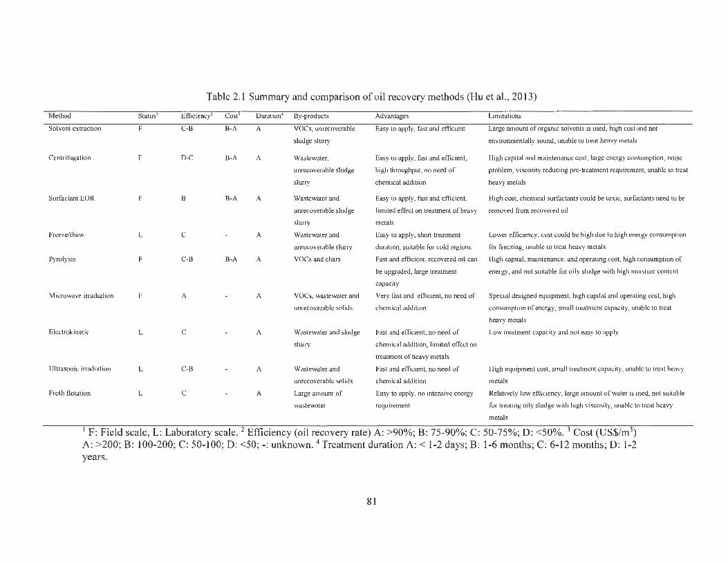
Method Status'
Solvent extraction F
Centrifugation F
Surfactant EOR F
Freeze/thaw L
Pyrolysis F
Microwave irradiation F
Electrokinetic L
Ultrasonic irradiation L
Froth flotation L
Table 2.1 Summary and comparison of oil recovery methods (Hu et al., 2013)
Efficiency' Cost3
C-B B-A
D-C B-A
B B-A
C
C-B B-A
A
C
C-B
C
Duration• By-products
A VOCs, unrecoverable
sludge slurry
A
A
A
A
A
A
A
A
Wastewater,
unrecoverable sludge
slurry
Wastewater and
unrecoverable sludge
slurry
Wastewater and
unrecoverable slurry
voes and chars
voes, wastewater and
unrecoverable solids
Wastewater and sludge
slurry
Wastewater and
unrecoverable sol ids
Large amount of
wastewater
Advantages
Easy to apply, fast and efficient
Easy to apply, fast and efficient,
high throughput, no need of
chemical addition
Easy to apply, fast and efficient,
Limitations
Large amount of organic solvents is used, high cost and not
environmentally sound, unable to treat heavy metals
High capital and maintenance cost, large energy consumption, noise
problem, viscosity reducing pre-treatment requirement, unable to treat
heavy metals
High cost, chemical surfactants could be toxic, surfactants need to be
limited effect on treatment of heavy removed from recovered oil
metals
Easy to apply, short treatment
duration, suitable for cold regions
Lower efficiency, cost could be high due to high energy consumption
for freezing, unable to treat heavy metals
Fast and efficient, recovered oil can High capital , maintenance, and operating cost, high consumption of
be upgraded, large treatment
capacity
Very fast and efficient, no need of
chemical addition
Fast and efficient, no need of
chemical addition, limited effect on
treatment of heavy metals
Fast and efficient, no need of
chemical addition
Easy to apply, no intensive energy
requirement
energy, and not suitable for oily sludge with high moisture content
Special designed equipment, high capital and operating cost, high
consumption of energy, small treatment capacity, unable to treat
heavy metals
Low treatment capacity and not easy to apply
High equipment cost, small treatment capacity, unable to treat heavy
metals
Relatively low efficiency, large amount of water is used, not suitable
for treating oily sludge with high viscosity, unable to treat heavy
metals
F: Field scale, L: Laboratory scale. 2 Efficiency (oil recovery rate) A: >90%; B: 75-90%; C: 50-75%; D: <50%. 3 Cost (US$/m3)
A: >200; B: 100-200; C: 50-100; D: <50; -: unknown. 4 Treatment duration A:< 1-2 days; B: 1-6 months; C: 6-12 months; D: 1-2 years.
81
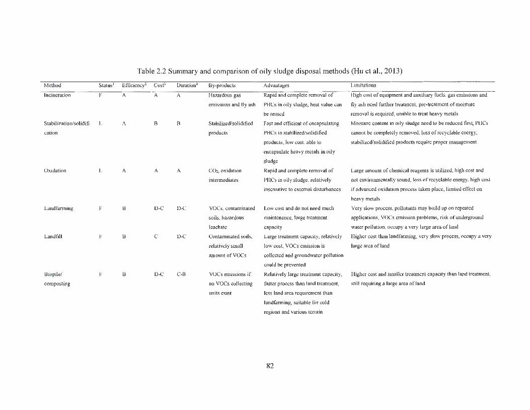
Table 2.2 Summary and comparison of oily sludge disposal methods (Hu et al., 2013)
Method Status' Efficiency2 Cost3 Duration4 By-products Advantages Limitations
Incineration F A A A Hazardous gas Rapid and complete removal of High cost of equipment and auxiliary fuels , gas emissions and
emissions and fly ash PHCs in oily sludge, heat value can fly ash need further treatment, pre-treatment of moisture
be reused removal is required, unable to treat heavy metals
Stabilization/solidifi L A B B Stabilized/solidified Fast and efficient of encapsulating Moisture content in oily sludge need to be reduced first, PHCs
cation products PHCs in stabilized/solidified cannot be completely removed, loss of recyclable energy,
products, low cost, able to stabilized/solidified products require proper management
encapsulate heavy metals in oily
sludge
Oxidation L A A A CO2, oxidation Rapid and complete removal of Large amount of chemical reagents is utilized, high cost and
intermediates PHCs in oily sludge, relatively not environmentally sound, loss of recyclable energy, high cost
insensitive to external disturbances if advanced oxidation process taken place, limited effect on
heavy metals
Land farming F B D-C D-C voes, contaminated Low cost and do not need much Very slow process, pollutants may build up on repeated
soils, hazardous maintenance, large treatment applications, VOCs emission problems, risk of underground
leachate capacity water pollution, occupy a very large area of land
Landfill F B C D-C Contaminated soils, Large treatment capacity, relatively Higher cost than landfarming, very slow process, occupy a very
relatively small low cost, VOCs emission is large area of land
amount ofVOCs collected and groundwater pollution
could be prevented
Biopile/ F B D-C C-B voes emissions if Relatively large treatment capacity, Higher cost and smaller treatment capacity than land treatment,
composting 110 voes collecting faster process than land treatment, still requiring a large area ofland
units exist less land area requirement than
landfarming, suitable for cold
regions and various terrain
82

Bioslurry F A C-8 C-8 Sludge slurry Fastest biodegradation approach,
great PHCs removal performance,
small land area requirement
High cost, small treatment capacity, need skilled operation,
maintenance and monitoring, slurry residues need proper
management
1 F: Field scale, L: Laboratory scale. 2 Efficiency (PHCs removal rate) A: >90%; B: 75-90%; C: 50-75%; D: <50%. 3 Cost (US$/m3)
A: >200; B: 100-200; C: 50-100; D: <50; -: unknown. 4 Treatment duration A: < l-2 days; B: l-6 months; C: 6-12 months; D: 1-2 years.
83
Chapter 3 Ultrasonic oil recovery and salt removal from refinery tank bottom sludge *
* The results of this work have been published as: Hu, G.J., Li, J.B., Ronald, R.W., and
Arocena, J., 2014. Ultrasonic oil recovery and salt removal from refinery tank bottom
sludge. Journal of Environmental Science and Health, Part A, 49, 1425-1435.
3 .1 Introduction
A significant volume of oily sludge is generated from the oil and gas industry during
various activities such as drilling, production, processing, and distribution. This kind of
sludge usually exists as a complex mixture of various petroleum hydrocarbons (PHCs),
water, metals, and solid particles (Hu et al., 2013). It has been recognized as a hazardous
waste in many countries because it contains a high concentration of toxic components,
including polycyclic aromatic hydrocarbons (PAHs) and heavy metals (Yan et al., 2012).
Any improper treatment of oily sludge poses serious threats to the environment and human
health, and thus requires effective management. In the past several years, various physical,
chemical, and biological methods have been proposed for oil recovery from oily sludge
through various methods or their combinations (Hu et al., 2013). These methods include
solvent extraction, centrifugation, surfactant enhanced oil recovery, freeze/thaw treatment,
pyrolysis, microwave heating, electro-kinetic treatment, froth flotation, and ultrasonic
irradiation (Hu et al., 2013; da Silva et al., 2012). Like many others, these methods are
associated with different advantages and limitations. Amongst them, ultrasonic irradiation
represents an emerging and promising technique due to its several inherent merits such as
high efficiency, short treatment duration, and chemical-free application (Bendicho et al.,
2012; Jin et al., 2012; Li et al., 2013). It has been reported to effectively remove adsorbed
84
materials from solid particles and decrease the stability of water/oil emulsions (Bendicho
et al., 2012; Nii et al., 2009; Pilli et al., 2011). The cavitation collapse due to ultrasonic
irradiation does not only affect the surface of solid particles but also penetrates into the
solid matrix, and could thus improve the separation of oil from solid particles and slurries
(Zhang et al., 2012; Abramov et al., 2009). Several studies to investigate the effect of
ultrasound on oil recovery from sludge have been conducted. For example, Xu et al. (2009)
found that oil constituents can be effectively stripped from the surface of solid particles in
oily sludge when using combined ultrasonic cavitation (28 kHz) and mechanical vibration
in an ultrasonic cleaning tank, and an overall oil recovery efficiency of 55.6% was
observed. Jin et al. (2012) combined ultrasonic irradiation and thermochemical cleaning
methods to treat oily sludge, and they found an oil recovery rate of up to 99.3%. Zhang et
al. (2012) reported an oil recovery rate of up to 80% from an oily sludge-water matrix by
using combined ultrasonic irradiation and freeze/thaw treatment process, but the effect of
temperature was not investigated.
Although ultrasonic irradiation shows great potential in oil recovery, a number of
issues still need to be addressed. An important one is that the recovered oil from sludge
still needs reprocessing for refinery feedstock; however, the salt content (e.g., sodium,
calcium, potassium, and magnesium chlorides) was either unknown or unreported in
previous oil recovery studies (Zhang et al., 2012). When compared to fresh crude oil,
recovered oil may contain more salts which can cause undesirable consequences in the
refining process (Ye et al., 2008). For example, high salt content in feedstock oil corrodes
equipment, obstructs oil pipes, and poisons catalysts in refineries (Abdul et al., 2006;
Mahdi et al., 2008). It is thus of great importance to have desalting treatment for the
recovered oil before its entry to a refinery. Ultrasonic irradiation could serve as an effective
85
salt removal method, as it has been reported to enhance the desalting process of crude oil.
For example, Ye et al. (2008) observed that the desalting efficiency of crude oil by
ultrasonic irradiation could reach 87.9%, and the salt content in ultrasound treated oil was
3 .85 mg/L which is suitable for refining. Gholam and Dariush (2013) also reported that the
salt removal from crude oil when using ultrasonic irradiation was 84% under optimal
conditions, and the treated crude oil could meet the salt requirement for refinery feedstock.
However, the desalting effect of ultrasonic irradiation on oily sludge has rarely been
reported. In fact, if ultrasonic irradiation treatment can reduce the salt content in recovered
oil, the cost for further desalting of such recovered oil as refining feedstock could then be
decreased.
Another issue with ultrasonic irradiation enhanced oil recovery is that it may generate
a large volume of wastewater which contains a high concentration of unrecoverable PH Cs
and undesirable salts (Zhang et al., 2012). Removal of such pollutants in wastewater could
increase the overall cost of oily sludge treatment. However, most previous studies have
focused on the improvement of oil recovery either by exploring the optimal ultrasonic
operating condition or by investigating the combined effect of ultrasonic irradiation with
other oil recovery methods (Jin et al., 2012; Xu et al., 2009). Little attention has been paid
to the wastewater generated from oily sludge treatment and the variation of pollutants in
wastewater under different treatment conditions. The objective of this chapter was then to
investigate the effects of ultrasonic irradiation on both oil recovery and salt removal from
refinery tank bottom sludge, as well as the concentrations of PH Cs and salt in wastewater
generated from sludge treatment. A number of factors including ultrasonic power,
treatment duration, sludge to water ratio, and sludge-water slurry temperature were studied
to examine their impacts on the treatment performance.
86
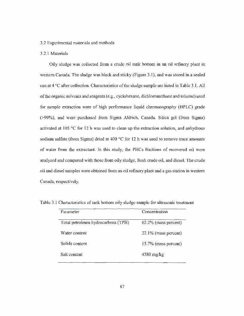
3 .2 Experimental materials and methods
3.2.1 Materials
Oily sludge was collected from a crude oil tank bottom in an oil refinery plant in
western Canada. The sludge was black and sticky (Figure 3.1), and was stored in a sealed
can at 4 cc after collection. Characteristics of the sludge sample are listed in Table 3.1. All
of the organic solvents and reagents ( e.g. , cyclohexane, dichloromethane and toluene) used
for sample extraction were of high performance liquid chromatography (HPLC) grade
(>99%), and were purchased from Sigma Aldrich, Canada. Silica gel (from Sigma)
activated at 105 cc for 12 h was used to clean up the extraction solution, and anhydrous
sodium sulfate (from Sigma) dried at 400 cc for 12 h was used to remove trace amounts
of water from the extractant. In this study, the PHCs fractions of recovered oil were
analyzed and compared with those from oily sludge, fresh crude oil, and diesel. The crude
oil and diesel samples were obtained from an oil refinery plant and a gas station in western
Canada, respectively.
Table 3.1 Characteristics of tank bottom oily sludge sample for ultrasonic treatment
Parameter
Total petroleum hydrocarbons (TPH)
Water content
Solids content
Salt content
87
Concentration
62.2% (mass percent)
22.1 % (mass percent)
15.7% (mass percent)
4580 mg/kg

Figure 3.1 Tank bottom sludge sample
3.2.2 Methods
Laboratory experiments were conducted to examine the efficiency of ultrasonic
irradiation on oil recovery and salt removal from oily sludge under different operating
conditions. Figure 3.2 illustrates the ultrasonic treatment system which utilized a 20 kHz
Misonix Sonicator 3000 generator. The effects of several experimental factors on oil
recovery and desalting performance were investigated, and these include ultrasonic power,
treatment duration, sludge-to-water (SW) ratio, and the initial temperature of sludge-water
slurry. The high viscosity of sludge was reduced by using different volumes of water and
by adjusting the temperature of sludge-water slurry. As a result, the sludge to water ratio
and the initial slurry temperature were considered to be two important experimental factors
in this study (Table 3.2). No chemicals were added to the treatment process because the
purpose of this study was to evaluate the sole effect of ultrasonic irradiation. For the
ultrasonic irradiation treatment, about 5 g of oily sludge was placed in a glass beaker and
88
mixed with a given volume of ultrapure water produced by a water purification system
(Milli-Q® Advantage AlO) according to the specified SW ratio, while the initial
temperature of slurry was controlled by using a hot plate (Thermo Scientific Cimarec ?x?
Ceramic Hotplate). When the pre-set initial temperature (e.g., 20, 40, 60 and 80 °C) was
reached, the hot plate was removed and ultrasonic irradiation was then applied. The 1.27
cm diameter titanium sonic probe was placed into the center of the SW slurry mixture for
ultrasonic irradiation. The changes in slurry temperature during treatment were recorded
using a noncontact infrared thermometer (OAK.TON® TempTestr IR). The experiments
were conducted using different combinations of experimental factor levels, and each
experiment was conducted in triplicate. In this study, the effect of direct heating on oily
sludge treatment was also investigated. The direct heating experiments were conducted by
heating the sludge-water slurry using a hot plate from an initial temperature of about 10 °C.
Once the slurry was heated to the pre-set temperature, the glass beaker was immediately
removed from the hotplate.
89
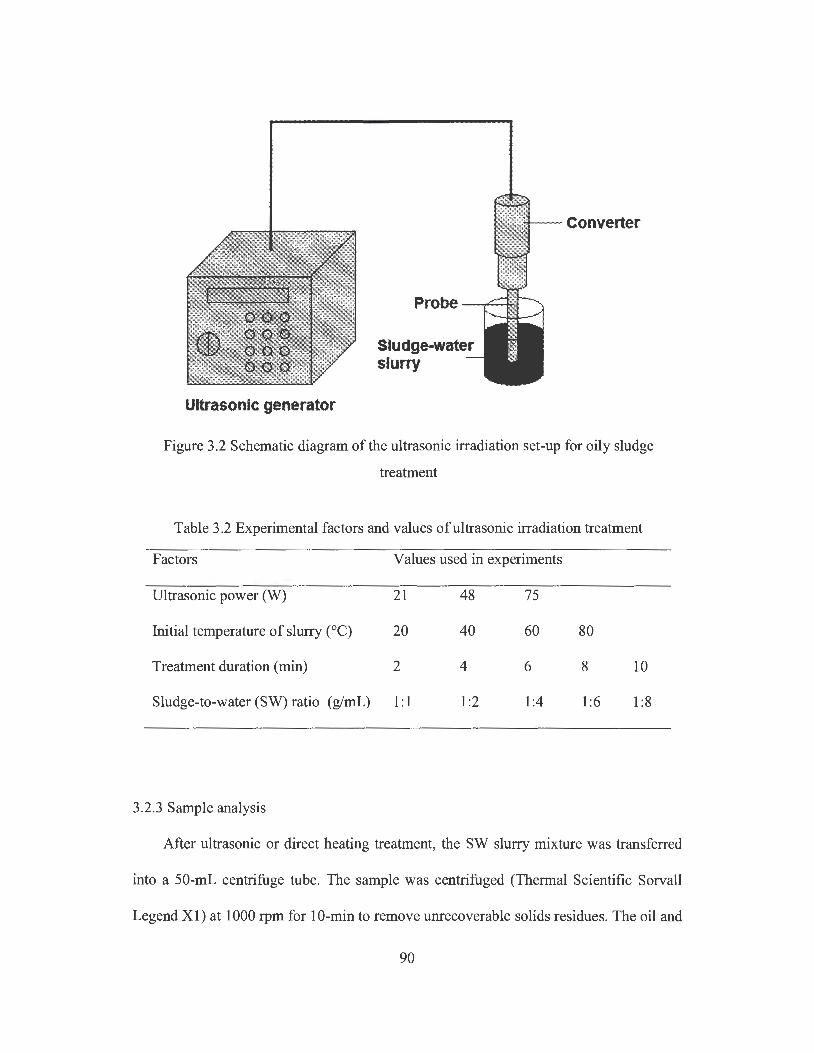
CD 0 .00 000 000 OQO
Ultrasonic generator
Converter
Sludge-water slurry
Figure 3.2 Schematic diagram of the ultrasonic irradiation set-up for oily sludge
treatment
Table 3.2 Experimental factors and values of ultrasonic irradiation treatment
Factors Values used in experiments
Ultrasonic power (Yv) 21 48 75
Initial temperature of slurry (0 C) 20 40 60 80
Treatment duration (min) 2 4 6 8 10
Sludge-to-water (SW) ratio (g/mL) 1: 1 1:2 1:4 1:6 1:8
3.2.3 Sample analysis
After ultrasonic or direct heating treatment, the SW slurry mixture was transferred
into a 50-mL centrifuge tube. The sample was centrifuged (Thermal Scientific Sorvall
Legend Xl) at 1000 rpm for 10-min to remove unrecoverable solids residues. The oil and
90
aqueous phases after centrifugation were then separated using a separatory funnel, and the
mass of the oil layer separated was measured as oil recovery. The concentrations of salt
and TPH in both the separated oil layer and aqueous phase (i.e., wastewater) were analyzed.
The salt content in oil was analyzed using the method given in American Society for
Testing and Materials (ASTM) D3230, while in the wastewater it was measured using an
electrical conductivity meter (VWR Symphony Conductivity Meter) (Majumdar et al.,
2002). To estimate the TPH concentration in the oil layer, approximately 1 g of recovered
oil sample was dissolved in 15 mL cyclohexane and then shaken (Talboy 3500 Orbital
Shaker) for mechanical extraction at 150 rpm for 1 h. After shaking, the extraction solution
was passed through a glass column packed with silica gel and anhydrous sodium sulfate
for cleanup. The cleaned extraction solution was collected and then evaporated using a
rotary evaporator (Yamato RE400) to remove the solvent and concentrate the PH Cs. The
concentration of TPH in the recovered oil was then calculated using the measured PH Cs
mass and oil sample mass. Similarly, the TPH concentration in the oily sludge sample was
also determined. In terms of measuring TPH in wastewater, the wastewater sample was
subjected to liquid-liquid extraction (3X) using cyclohexane (with a volume ratio of 8:3),
with the remaining procedures being similar to those used for measuring TPH in the oil
layer sample. The detailed descriptions of sample extraction and analysis can be found in
Zhang et al. (2012). The PHC recovery rate was defined as follows:
(1)
91
Where R0 is oil recovery rate (%), Co1 and Cs are TPH concentrations (mg/g) in the
recovered oil layer and original sludge, respectively, Mo, is the total mass of recovered oil
(g) after separation, and Ms is the mass of oily sludge (g) used for each experimental
treatment.
The proportions of different PH Cs fractions in recovered oil, oily sludge, fresh crude
oil, and diesel were analyzed using a Varian CP-3800 Gas Chromatograph with flame
ionization (GC-FID). The external standard method was used to calculate PHCs
concentration, while decane (CJO), hexadecane (C16), tetratriacontane (C34), and
pentacontane (Cso) were used as standard compounds to determine PHCs fractions (CCME,
2001). The PHCs fractions Fl, F2, F3 and F4 were defined as the group of petroleum
hydrocarbons from C6 to CJO, CJO to C16, C16 to C34, and C34 to Cso, respectively. About 1
g of recovered oil, oily sludge, fresh crude oil, and diesel were dissolved in 20 mL of
cyclohexane, and then the solution was passed through the silica gel column cleanup and
subsequent rotary evaporation as discussed above. After evaporation, PHCs in the flask
were completely dissolved in 20 mL of toluene, and 2 mL of each solution was collected
for GC-FID analysis. The ZB-capillary column (Phenomenex Torrance, CA) with 30 m x
0.25 mm inner diameter and 0.24-µm film thickness was used. The GC analysis conditions
were set up with an injection volume of 1 µL, injector and detector (FID) temperature at
320 °C, and carrier gas of helium at a constant flow rate of 1.5 mL/min. The splitless
injection mode was performed on the 1079 PTV injector and after 0.7 min the split mode
was activated at a split ratio of 10: 1. The capillary column temperature was initially held
at 50 °C for 1 min, then ramped at 15 °C/min to 110 °C and further increased at 10 °C/min
to 300 °C and then held for 11 min. The total running time for each sample analysis was
about 3 5 min.
92
3.3 Results and discussion
3.3.1 Temperature change during ultrasonic treatment
Figure 3.3 presents the temperature change in the SW slurry mixture (with an initial
slurry temperature of 25 °C) after ultrasonic irradiation treatment; as seen, this change can
vary significantly. A more dramatic increase was found for samples treated with high
ultrasonic irradiation power than for those treated with low ultrasonic power. For example,
when using an ultrasonic power of75 W, the slurry temperature increased from 25 to 77 °C
within 6 min of ultrasonic treatment before reaching a plateau. However, at an ultrasonic
power of21 W, the slurry temperature only increased to 61 °C after 6 min of treatment and
thereafter it remained stable. This is generally in agreement with results obtained from
previous studies on sewage sludge treatment by ultrasonic irradiation (Dewil et al. , 2006).
When ultrasonic irradiation is applied to the SW medium, micro-bubbles form due to the
different pressures caused by ultrasonic waves, and the violent collapse of these micro-
bubbles when they reach an unstable size would produce shock waves and rapid increase
in temperature (Pilli et al. , 2011). As it can be seen in Figure 3.4, three layers including oil
layer (top), water layer (middle), and solid residue (bottom) were separated after ultrasonic
irradiation treatment. The water layer was not clear, indicating it might contain unwanted
impurities such as fine solids and dispersed PH Cs, which requires proper treatment before
discharging into the environment.
93
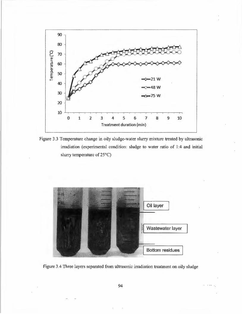
90
80 -u 70 !.-4) ... .a 60 (I)
~ a.. so E CJ l- -0-21 W
40 -0-48 W
30 ~ 75W
20
10 0 1 2 3 4 5 6 7 8 9 10
Treatment duration (min)
Figure 3.3 Temperature change in oily sludge-water slurry mixture treated by ultrasonic
irradiation ( experimental condition: sludge to water ratio of 1 :4 and initial
slurry temperature of 25°C)
Oil layer
Wastewater layer
Bottom residues
Figure 3.4 Three layers separated from ultrasonic irradiation treatment on oily sludge
94
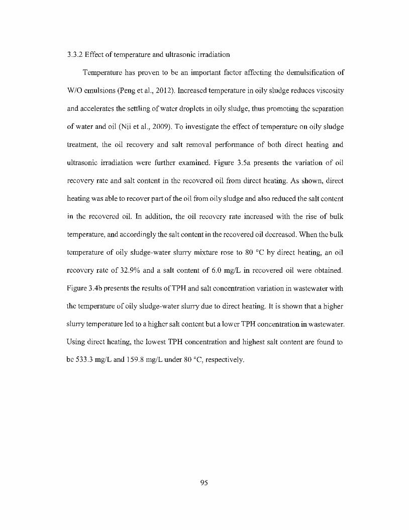
3.3.2 Effect of temperature and ultrasonic irradiation
Temperature has proven to be an important factor affecting the demulsification of
W/0 emulsions (Peng et al., 2012). Increased temperature in oily sludge reduces viscosity
and accelerates the settling of water droplets in oily sludge, thus promoting the separation
of water and oil (Nii et al., 2009). To investigate the effect of temperature on oily sludge
treatment, the oil recovery and salt removal performance of both direct heating and
ultrasonic irradiation were further examined. Figure 3.5a presents the variation of oil
recovery rate and salt content in the recovered oil from direct heating. As shown, direct
heating was able to recover part of the oil from oily sludge and also reduced the salt content
in the recovered oil. In addition, the oil recovery rate increased with the rise of bulk
temperature, and accordingly the salt content in the recovered oil decreased. When the bulk
temperature of oily sludge-water slurry mixture rose to 80 °C by direct heating, an oil
recovery rate of 32.9% and a salt content of 6.0 mg/L in recovered oil were obtained.
Figure 3.4b presents the results ofTPH and salt concentration variation in wastewater with
the temperature of oily sludge-water slurry due to direct heating. It is shown that a higher
slurry temperature led to a higher salt content but a lower TPH concentration in wastewater.
Using direct heating, the lowest TPH concentration and highest salt content are found to
be 533.3 mg/Land 159.8 mg/L under 80 °C, respectively.
95
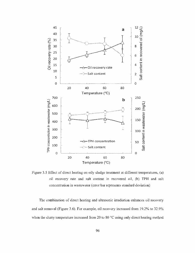
45 a 12 :]' -C')
40 E 10 ::::-
~ 35 ·a 0 "'O .._ Q) 30 8 Q) - .... «l Q) .... > ~ 25 0
(.) Q) 6 ~ > 0 20 .£; (.) Q) -.... 15 4 C:
Q)
6 -:ll- Oil recovery rate -C: 10 0
-0-Salt content 2 (.) -5 «l
(/)
0 0 20 40 60 80
Temperature (°C) 700 b 250
::J' -- ::J" O> g 600 -O') ... 200 E 2 -(,;) 500 ..... s: Q) -2 Ctl If> 150 ~ ~ 400 -(/) .!: ro C 300 ~ ,g 100 .E ~ -c C
200 Q) (!) -<.;) -i:l-TPH concentration C: C 50 0 0 (.) <.;) 100 ..... I -0-Salt content Ctl Q. (/) I- 0 0
20 40 60 80 Temperature (°C)
Figure 3.5 Effect of direct heating on oily sludge treatment at different temperatures, (a)
oil recovery rate and salt content in recovered oil, (b) TPH and salt
concentration in wastewater ( error bar represents standard deviation)
The combination of direct heating and ultrasonic irradiation enhances oil recovery
and salt removal (Figure 3.6). For example, oil recovery increased from 19.2% to 32.9%
when the slurry temperature increased from 20 to 80 °C using only direct heating method
96

(Figure 3 .Sa). However, it increased from 33 .8% to 51.6% when the initial slurry
temperature increased from 20 to 80 °C in the treatment using an ultrasonic power of 21
W and a treatment duration of 6 min, and accordingly the salt content in recovered oil
decreased from 7. 7 mg/L to 5. 0 mg/L. This shows that ultrasonic irradiation improved the
oil recovery of direct heating by 14.5-21.6% under lower ultrasonic power (i.e., 21 W)
conditions. However, the increase in initial slurry temperature by direct heating showed
very little performance enhancement when using relatively higher ultrasonic power. For
example, the oil recovery rates were 57.9% and 59.6% for treatments with ultrasonic power
of 48 W and 75 W when the initial slurry temperature was 80 °C, which were only slightly
higher than those (i.e., 52.8% and 59.1 %) for treatments with an initial temperature of
20 °C (Figure 3.6a). The salt content in recovered oil also showed little change (Figure
3.6b ). When the initial slurry temperature was increased from 20 to 80 °C by direct heating,
the TPH concentration in wastewater decreased from 1616 to 1330 mg/L (Figure 3.6c),
and the salt content in wastewater (Figure 3.6d) increased from 471 to 534 mg/L at an
ultrasonic power of 21 W, but a very slight change of such concentrations was observed at
an ultrasonic power of 75 Wand 48 W. The result shows that it is unnecessary to raise the
initial slurry temperature when applying relatively higher ultrasonic power for oily sludge
treatment because high ultrasonic power could rapidly increase the bulk temperature of
slurry to a high level as shown in Figure 3.3 .
97
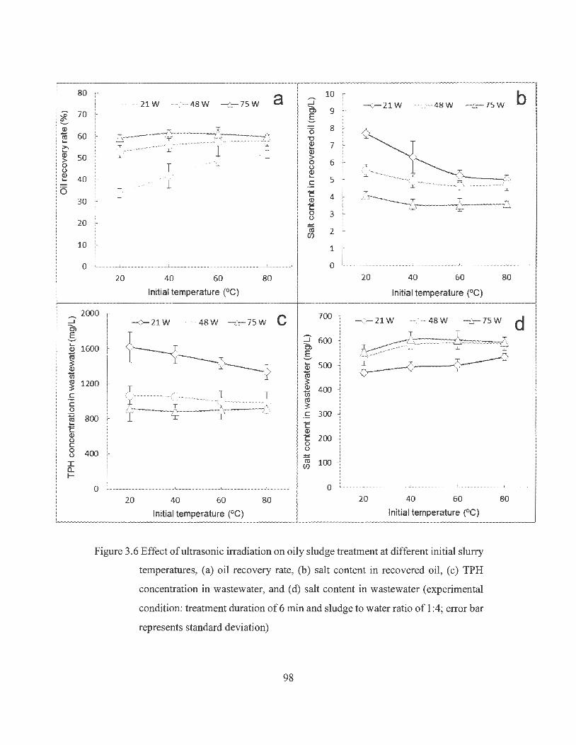
;i" 0 ..._, Q) ro ... >. ... Q) > 0 (.) Q) ... 6
:::::i' Cl s ... Q)
ro ~ Q)
cii co ~ C C 0 ro ... c Q) (.) C 0 (.)
I a.. 1--
80 a 10 -21W -(;- 48W --i:s- 75 W _J -<r- 21 W -("-- 48 W -t::- 75W Cl 70 s 9
fr ·5 8 60 ~ ·-:l'). "C
' ' .J.. Q) 7 <' ~ J:!- I ... Q)
50 ·:i. · > 0 6 T (.) / T ..... Q) ,~....____ 40 ... 5 . A
1 C ;.l.._ ____ .,-,
c ~/ :r! 30 Q) 4
c '=' ':r ._:,
0 3 (.) 20 ..... co 2 Cf)
10 1
0 0 20 40 60 80 20 40 60 80
Initial temperature (°C) Initial temperature (°C)
2000 C 700 -<>- 21 W - 0-48W - b:- 75 W --<>- 21 W --::r- 48 W --fr-75 W
:::::i' 600 :i;
~ 6 1600 Cl ~~ I E '-" 'I' ... 500 Q)
ro 1200 ~
~ Q) 400
~---C~' I 1i5 co ~ ~
800 1i C 300 ~ Q) c 200 0
400 (.) ..... co 100 Cf)
0 ··············---l.--··-····---1--------··-· 0 20 40 60 80 20 40 60 80
Initial temperature (°C) Initial temperature (°C)
Figure 3.6 Effect of ultrasonic irradiation on oily sludge treatment at different initial slurry
temperatures, (a) oil recovery rate, (b) salt content in recovered oil, (c) TPH
concentration in wastewater, and ( d) salt content in wastewater ( experimental
condition: treatment duration of 6 min and sludge to water ratio of 1 :4; error bar
represents standard deviation)
98
b
d
3.3.3 Effects of ultrasonic power and treatment duration
As discussed above, there is no need to raise the initial slurry temperature because
ultrasonic irradiation greatly increases the temperature of the SW slurry medium within a
short time period, and an initial temperature between 20 and 40 °C achieved satisfactory
oil recovery performance (Figure 3.6). As a result, the initial slurry temperature of 25 °C
was selected in this study to further investigate the effects of ultrasonic irradiation on oily
sludge treatment. The oil recovery performance was improved either by increasing
ultrasonic power or treatment duration (Figure 3.7a). Under the same treatment duration,
higher ultrasonic power illustrated better oil recovery performance. For example, after 2
min of ultrasonic treatment, the oil recovery rate from sludge was 27.0%, 35.7%, and 49.3%
at an ultrasonic power of 21, 48, and 75 W, respectively. As shown in Figure 3.8b, no
obvious separation between water and oil was observed from the sludge-water mixture,
indicating that the low ultrasonic power and short treatment duration were not effective for
oil and water separation. However, such separation was noticeable when higher ultrasonic
power and longer treatment duration were applied (Figure 3.8c). For example, under an
ultrasonic power of 48 W, oil recovery significantly increased from 35.7% to 61.2% as the
treatment duration was extended from 2 to 8 min, and then it approached an asymptote
which indicates that further extension of treatment duration is unnecessary.
99
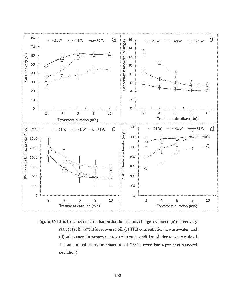
80
70
,....., 60 -£.
~ >, .... Q) 50 > 0 (.) Q) 40 a:: 6 30
20
10
0
s,:l 3500 a, E L.. Q) 3000 iii s: Q)
1n 2500 ~ C:
C: 2000 0
"" ~ c Q) 0 1500 C: 0 0
I 1000 0.. I-
500
0
a 16 -<>- 21 W ----c".)--- 48 W -&-75W :::;- -<>- 21W -6-48W -rr-75W C) E 14 '-'
·o T "O y Q) 12 Q) >
~ 0 (.) 10 ~ " ~ ', .5 c 8 Q) c 0 6 (.) -
1a (fJ 4
2
0 2 4 6 8 10 2 4 6 8
Treatment duration (min) Treatment duration (min)
-"- 21 W ~ ,.:- 48W -tr- 75 W C 700 '(> 21W ......-:r- 48W -tr- 75W ......... ...J --0)
E 600 '-' Q) (V; ii! ~ 500 ,$ $ 7/ l -i> VI (I)
~ 400 y / .5 c IT'(
Q) ;....
300 c ¢ 0 (.)
i\j 200 (fJ
100
.................. J. ................ .i. ................... .l .... - ........... 1.--.... 1 ................... l ......... - ..... _J ____ I -- i 0 2 4 6 8 10 2 4 6 8
Treatment duration (min) Treatment duration (min)
Figure 3. 7 Effect of ultrasonic irradiation duration on oily sludge treatment, (a) oil recovery
rate, (b) salt content in recovered oil, ( c) TPH concentration in wastewater, and
( d) salt content in wastewater ( experimental condition: sludge to water ratio of
1 :4 and initial slurry temperature of 25°C; error bar represents standard
deviation)
100
b
10
d
1>
10

Figure 3.8 Mixtures of oily sludge and water, (a) before ultrasonic treatment, (b) after
treatment under ultrasonic power of 21 W and duration of 2 min, ( c) after
treatment under ultrasonic power of 75 W and duration of 6 min ( experimental
condition: sludge to wat er ratio of 1 :4 and initial slurry temperature of 25°C)
Under an ultrasonic power of 75 W, the oil recovery rate also increased with treatment
duration from 2 to 6 min (i.e., highest oil recovery of 62.2% at 6 min), but it slightly
decreased with treatment duration beyond 6 min. Jin et al. (2012) utilized an ultrasonic
cleaning tank for oily sludge treatment and they also found that the oil recovery rate
increased significantly in the first 15 min of treatment due to the high rates of initial
desorption. However, when the treatment duration was extended, they found that the re-
adsorption of removed oil onto the solid particle surfaces increased, and a further
enhancement of oil recovery could not be achieved when the rate of desorption was equal
to that ofre-adsorption (Jin et al. , 2012)
Oil recovery performance under the same temperature using ultrasonic irradiation was
more promising when compared with only direct heating. For example, when the slurry
was treated for 2 min using an ultrasonic power of 21 W, its temperature increased to 40 °C
101

(Figure 3.3), and its oil recovery rate was 27.0% (Figure 3.7a), which is slightly higher
than that (i.e. , 23.3%) of direct heating to 40 °C (Figure 3.5a). The difference in oil
recovery rate between direct heating and ultrasonic irradiation became more significant at
higher temperature. For example, the oil recovery rate at 80 °C by direct heating was 32.9%
(Figure 3.5a), but reached 62.2% after 6 min of ultrasonic treatment at a power of 75 W
(Figure 3.7a) under which the slurry temperature increased from 25 to 75 °C (Figure 3.3).
The promising oil recovery performance of ultrasonic irradiation may be attributed to its
cavitation effect. The sudden and violent collapse of a considerably large number of micro-
bubbles during ultrasonic irradiation could generate strong hydro-mechanical shear forces
in the vicinity area of solid particles, which would then break the aggregates of solid
matrices and release the adsorbed or trapped PHCs (Pilli et al. , 2011 ; Xu et al. , 2009; Flores
et al., 2007). Chu et al. (2001) found that direct heating alone was insufficient to
disintegrate the floe structure in wastewater activated sludge, but the combined ultrasonic
irradiation and heating produced satisfactory results in sludge floe disintegration. The
strong hydro-mechanical shear forces generated during ultrasonic irradiation can also
cause disturbances in the bulk liquid and introduce a drag effect on the droplets. Under this
effect, small droplets of the dispersed-phase (i.e., water in W/0 emulsion) move faster than
the larger droplets, and the faster movement of these small droplets increases their collision
frequency with other water droplets, leading to an increased chance of forming larger water
droplets which would then enhance the separation of water and oil (Nii et al. , 2009).
As shown in Figure 3.7b, the salt content in recovered oil decreased with increasing
treatment duration and ultrasonic power. The decrease was more significant for the
treatment with an ultrasonic power of21 W, where salt content decreased from 12.8 to 5.7
mg/L when the treatment duration increased from 2 to IO min. Under an ultrasonic power
102

of 75 W, the salt content in recovered oil decreased from 5.7 to 4.3 mg/L when the
treatment duration was increased from 2 to 10 min, and the lowest salt content of 4.2 mg/,
which meets the salt content norm of 5 mg/Lin feedstock oil for most refineries (Ye et al.,
2008), was observed at a treatment duration of 8 min. This is in agreement with the results
from other studies of crude oil desalting using ultrasound. For example, Gholam and
Dariush (2013) reported that an increase of ultrasonic power to 50 W resulted in a decrease
of salt content in crude oil at a constant irradiation duration, and the increase of treatment
duration until 6 min under a given ultrasonic power also showed a positive desalting effect
on crude oil. However, a further increase in ultrasonic power beyond 50 Wand treatment
duration beyond 6 min didn't show further desalting of crude oil.
TPH concentration in wastewater decreased with increasing ultrasonic power and
treatment duration (Figure 3.7c and 3.7d). As Figure 3.9 shows, all wastewater separated
from oil recovery treatment were turbid because the presence of emulsified PHCs and
solids. The wastewater from the treatment using lower ultrasonic power and shorter
treatment duration showed darker colour than that from high ultrasonic power and longer
treatment duration, indicating higher TPH concentration within it. However, the salt
content in wastewater varied in an opposite trend. The wastewater contained less TPH but
more salt content from oily sludge treatments with higher ultrasonic power and longer
treatment duration. Under an ultrasonic power of 21 W, the TPH concentration in
wastewater decreased significantly from 2600.0 to 1622.2 mg/L, and the salt content
increased from 279.0 to 448.8 mg/L when the treatment duration increased from 2 to 6 min.
As the treatment duration increased to 10 min, the TPH concentration slightly decreased
to 1444.4 mg/Land salt content slightly increased to 506.1 mg/L.
103
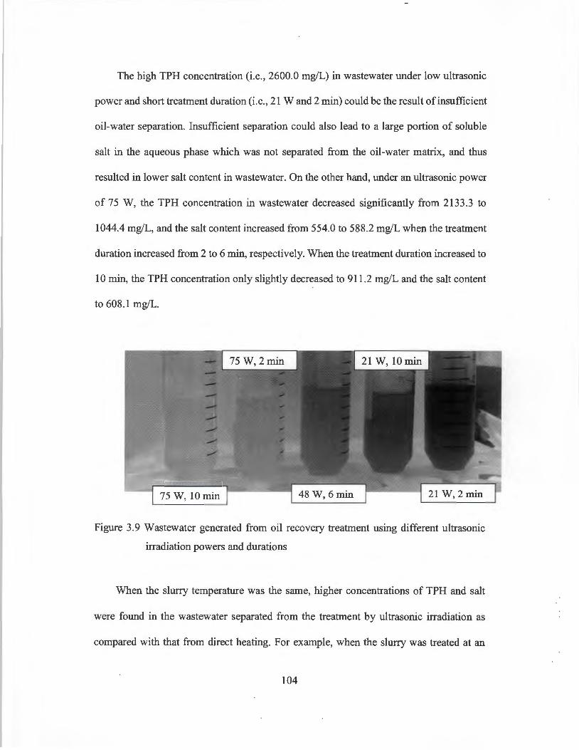
The high TPH concentration (i.e., 2600.0 mg/L) in wastewater under low ultrasonic
power and short treatment duration (i.e., 21 Wand 2 min) could be the result of insufficient
oil-water separation. Insufficient separation could also lead to a large portion of soluble
salt in the aqueous phase which was not separated from the oil-water matrix, and thus
resulted in lower salt content in wastewater. On the other hand, under an ultrasonic power
of 75 W, the TPH concentration in wastewater decreased significantly from 2133.3 to
1044.4 mg/L, and the salt content increased from 554.0 to 588.2 mg/L when the treatment
duration increased from 2 to 6 min, respectively. When the treatment duration increased to
10 min, the TPH concentration only slightly decreased to 911.2 mg/Land the salt content
to 608.1 mg/L.
Figure 3.9 Wastewater generated from oil recovery treatment using different ultrasonic
irradiation powers and durations
When the slurry temperature was the same, higher concentrations of TPH and salt
were found in the wastewater separated from the treatment by ultrasonic irradiation as
compared with that from direct heating. For example, when the slurry was treated at an
104
ultrasonic power of 75 W, the temperature rose to 77 °C in 8 min (Figure 3.3), and the
concentration of TPH and salt in wastewater were 955.4 mg/L (Figure 3.7c) and 609.9
mg/L, respectively (Figure 3.7d). In contrast, when the slurry temperature was increased
to 80 °C by direct heating, the TPH and salt content in the wastewater were 383.1 and
195.8 mg/L, respectively (Figure 3.5b ). In general, soluble salts in oily sludge were
dissolved in the water phase of W /0 emulsion, and this water phase was surrounded by a
continuous oil phase. Under higher ultrasonic power and longer treatment duration, a
higher water-oil separation efficiency (also meaning a higher oil recovery rate) was
obtained.
The higher oil recovery could then lead to a lower TPH concentration in wastewater.
Such higher demulsification efficiencies of oily sludge could also lead to less salt content
in the separated oil phase but higher salt content in the separated wastewater (Gholam and
Dariush, 2013). When the treatment duration was extended beyond 6 min, the further
enhancement effect of ultrasonic irradiation on oil recovery cannot be achieved as
indicated above, and thus the TPH concentration in wastewater didn't show further
decrease nor the salt content in wastewater showed further increase. Although the TPH
concentration in wastewater was significantly reduced under a relatively high ultrasonic
power and a longer irradiation time, it is still very high (i.e., 911.1 mg/Lat 75 Wand 10
min) as compared to that in common petroleum refinery wastewater effluents (Fakhru ' l-
Razi et al., 2009). The high salt content in refinery wastewater is also of environmental
concern (Zhao et al., 2011 ). Therefore, wastewater from oily sludge treatment by ultrasonic
irradiation could be a secondary pollution problem and must therefore be properly handled.
105
3 .3 .4 Effect of sludge to water ratio
Higher ultrasonic power was generally associated with a higher oil recovery rate and
a lower salt content in recovered oil (Figure 3.7). Under the same ultrasonic power level,
the oil recovery rate increased with decreasing sludge to water ratio, but further decrease
of sludge to water ratio beyond a certain value instead resulted in a decrease of oil recovery.
Too much water in the oily sludge-water mixture could have negative impact on the
demulsification process by ultrasonic irradiation. When the sludge to water ratio was below
1 :4, both oil recovery and desalting were reduced under different ultrasonic power levels.
For example, under an ultrasonic power of 75 W, oil recovery reached a maximum of 56.6%
(Figure 3 .1 Oa) and the salt content in recovered oil decreased to as low as 3 .2 mg/L (Figure
3 .1 Ob) at a sludge to water ratio of 1 :4. When the ultrasonic power was 48 W, the highest
oil recovery (i.e., 51.4%) occurred at sludge to water ratio of 1 :2, but no significant
difference of oil recovery was observed between oily sludge treatments at sludge to water
ratio of 1 :2 and 1 :4.
Too low water content (i.e. , too high sludge to water ratio) could result in increased
viscosity of the oily sludge-water slurry mixture which could then impede the formation
and collapse of cavitation micro-bubbles, leading to weakened sonication effect on oil
recovery and desalting (Pilli et al. , 2011). For example, Feng and Aldrich (2000)
investigated the PHCs contaminated soil remediation by ultrasonic irradiation, and they
found that the increased solid concentration to above 50% in the oily slurry could
significantly inhibit the ultrasonic cavitation process. Our previous study reported that the
highest oil recovery rate (i.e. 80%) occurred at an ultrasonic power of 66 Wand a sludge
to water ratio of 1 :2 when using a combined ultrasonic irradiation and freeze/thaw
treatment process (Zhang et al. , 2012). It is greater than that (i.e. 62.2%) observed in this
106

work ( e.g., 75 W, sludge-water ratio of 1 :4, when using only ultrasonic irradiation) (Figure
3.7a) because the freeze/thaw process could have a synergic effect on the ultrasonic
irradiation process (Zhang et al. , 2012).
107

~ e..... >, ... Q) > 0 (.) Q) er: 6
~ E .... .'!l "' 3: .,
1iS "' 3: -~ C 0 ~ .b C ., 0 C 0 0 I a. I-
70 -0- 21 W -C>- 48W -ls- 75 W a ::;- 16
r .A- 21W --<>- 48 W -ls- 75W Ol .s 14 60 ·5
-0 I Q) 12 so Q) r / { > 0
(.J 10 ~ 40 .!; c 8 Q)
30 c 0 6 (.J
20 iii C/J 4
10 2
0 ··'"······-···-···1 ...................................... 1 ....................................... 1 ··············-·-·······--·-·····J.. .... 0 ..................... - .......... .!
1:1 1:2 1:4 1:6 1:8 1:1 1:2 1:4 1:6 1:8
Sludge/water ratio Sludge/water ratio
3000 -<- 21 W --(-48W -&- 75W C ....... 1600 ---v- 21 W -:.:;;- 48 W -ir-' 75 W ...J Ol .s
2500 Q) 1400 1a 3: 1200 Q)
2000 Kl 3: 1000
.!; ?: 1500 800 Q)
?: 0 (.J
600 iii 1000 C/J
f 400 500
200
0 0 1:1 1:2 1:4 1 :6 1:8 1:1 1 :2 1:4 1:6
Sludge/water ratio Sludge/water Ratio
Figure 3.10 Effect of sludge to water ratio on the performance of oily sludge treatment by
ultrasonic irradiation, (a) oil recovery rate, (b) salt content in recovered oil, ( c)
TPH concentration in wastewater, and ( d) salt content in wastewater
( experimental condition: treatment duration of 6 min and initial slurry
temperature of 25°C; error bar represents standard deviation)
108
1:8
b
d
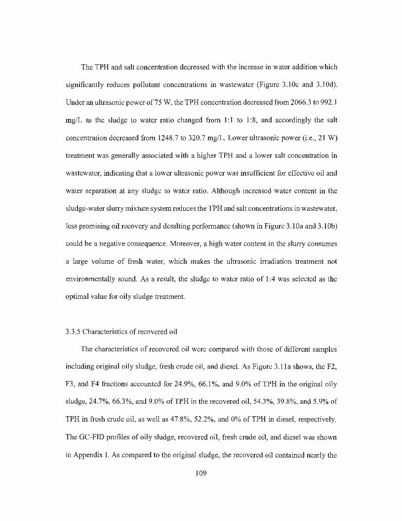
The TPH and salt concentration decreased with the increase in water addition which
significantly reduces pollutant concentrations in wastewater (Figure 3.10c and 3.10d).
Under an ultrasonic power of 75 W, the TPH concentration decreased from 2066.3 to 992.1
mg/L as the sludge to water ratio changed from 1: 1 to 1 :8, and accordingly the salt
concentration decreased from 1248.7 to 320.7 mg/L. Lower ultrasonic power (i.e., 21 W)
treatment was generally associated with a higher TPH and a lower salt concentration in
wastewater, indicating that a lower ultrasonic power was insufficient for effective oil and
water separation at any sludge to water ratio. Although increased water content in the
sludge-water slurry mixture system reduces the TPH and salt concentrations in wastewater,
less promising oil recovery and desalting performance (shown in Figure 3.10a and 3.10b)
could be a negative consequence. Moreover, a high water content in the slurry consumes
a large volume of fresh water, which makes the ultrasonic irradiation treatment not
environmentally sound. As a result, the sludge to water ratio of 1 :4 was selected as the
optimal value for oily sludge treatment.
3.3.5 Characteristics of recovered oil
The characteristics of recovered oil were compared with those of different samples
including original oily sludge, fresh crude oil, and diesel. As Figure 3 .11 a shows, the F2,
F3, and F4 fractions accounted for 24.9%, 66.1 %, and 9.0% of TPH in the original oily
sludge, 24.7%, 66.3%, and 9.0% ofTPH in the recovered oil, 54.3%, 39.8%, and 5.9% of
TPH in fresh crude oil, as well as 47.8%, 52.2%, and 0% of TPH in diesel, respectively.
The GC-FID profiles of oily sludge, recovered oil, fresh crude oil, and diesel was shown
in Appendix I. As compared to the original sludge, the recovered oil contained nearly the
109

same percentage ofF2, F3 and F4 fractions, indicating that ultrasonic irradiation under the
operating conditions in this study did not rupture the long-chain and heavy PHCs. Fresh
crude oil and diesel contained more F2 fraction (i.e., light PHCs) than recovered oil, but
more F3 and F4 fractions (i.e., heavy PHCs) were found in the latter. Figure 3.10b shows
that the recovered oil contained a higher percentage of TPH (i.e., 80.4%) than fresh crude
oil (i.e. , 71.7%).
As shown in Figure 3.1 lb, oily sludge contained the lowest TPH content (i.e. , 62.2%),
while the refined product (i.e., diesel) showed the highest TPH content (i.e., 87.7%). These
results revealed that ultrasonic irradiation could significantly increase TPH content in the
recovered oil, and the recovered oil contains more valuable PHCs content than crude oil.
The present study also showed that the recovered oil from the ultrasonic irradiation of oily
sludge contained low salt content (i.e. , as low as 3.5 mg/L). Consequently, the recovered
oil is of better quality as an energy source when compared with the original oily sludge
and crude oil, and it can be used as feedstock in conventional refmeries.
110
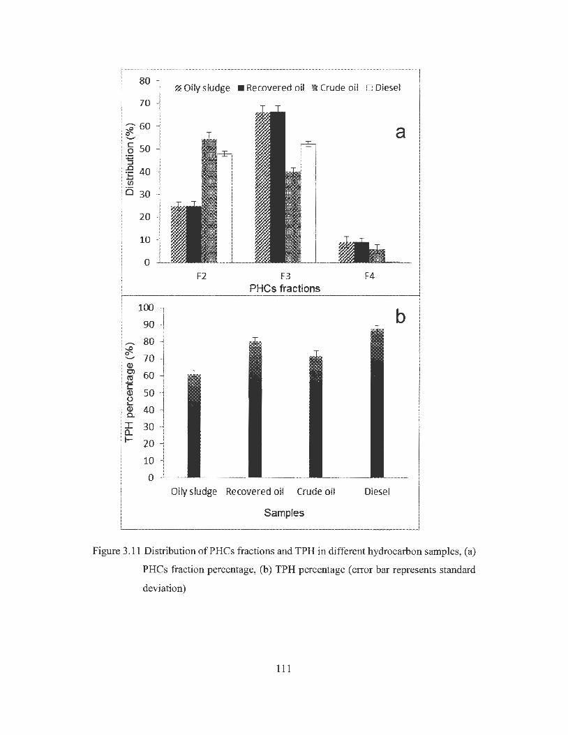
80 ~ Oily sludge • Recovered oil it Crude oil o Diesel
70
~ 60 0 -C 50 a :.::; :::s .c 40 ·;:: ...... (/)
0 30
0 F2 F3 F4
PHCs fractions
100 b 90
....-.. 80 '::?. 0 70 -Q) C) 60 ro c
50 Q) (.) L.. <l) 40 a. I 30 a.. I- 20
10
0 Oily sludge Recovered oil Crude oil Diesel
Samples
Figure 3.11 Distribution of PH Cs fractions and TPH in different hydrocarbon samples, (a)
PH Cs fraction percentage, (b) TPH percentage ( error bar represents standard
deviation)
111

3 .4 Conclusions
Ultrasonic irradiation was illustrated as a promising approach for oil recovery and
desalting of refinery tank bottom sludge. About 62.2% of PH Cs was recovered from the
sludge at an ultrasonic power of 75 W and a treatment duration of 6 min. The optimal
sludge-to-water ratio was found to be 1 :4, yet too high or too low water content in the
sludge slurry system led to lower oil recovery rate. It was found that the salt content in
recovered oil was decreased to less than 5 mg/L after 6 min of ultrasonic irradiation at a
power of 75 W, which can meet the salt content requirement for feedstock oil in most
refineries. The recovered oil contained about 80.4% TPH which is higher than in crude oil
(i.e., 71.7%). Its TPH contained similar percentages of F2, F3 and F4 fractions as the
original sludge, which implies that ultrasonic irradiation did not break the heavy PHCs. It
was found that the separated wastewater from ultrasonic irradiation contained relatively
high concentrations of TPH and salt which require proper treatment, although a higher
ultrasonic power led to a higher salt concentration and a lower TPH concentration. In
summary, ultrasonic irradiation is shown to be an effective method for refinery oily sludge
treatment for the purpose of recovering high-quality oil with more PH Cs and less salt.
112
Chapter 4 Oil recovery from refinery oily sludge through ultrasonic assisted extraction *
*The results of this work have been accepted for publication in the Journal of
Environmental Science and Health, Part A. in 2016.
4.1 Introduction
Among various oil recovery treatment methods, solvent extraction as a simple process
of separating PHCs from various matrixes has been proven effective (Zubaidy and
Abouelnasr, 2010; Taiwo and Otolorin, 2009). In this process, oily waste and solvent are
mixed to ensure adequate miscibility of oil in solvent, followed by the separation of oil
from solvent through distillation of the oil/solvent mixture. Most water and solids are
rejected as impurities which can be removed by gravitational settling or centrifugation (Al-
Zahrani and Putra, 2013) . Several efforts have been made to investigate the oil recovery
from oily wastes by solvent extraction in recent years. For example, Avila-Chavez et al.
(2007) employed supercritical ethane and dichloromethane to treat oily sludge and found
that more than 50% of oil can be recovered; Taiwo and Otolorin (2009) reported an oil
recovery up to 67.5% when using hexane and xylene extraction on tank bottom sludge;
Zubaidy and Abouelnasr (2010) found that methyl ethyl ketone (MEK) and light petroleum
gas condensate (LPGC) can recover 39% and 32% of oil from oily sludge when the
solvent-to-sludge ratio was 4: 1.
Traditional solvent extraction process is usually associated with a number of
drawbacks, such as long extraction time, low extraction efficiency, large solvent volume,
and high cost. Some alternative approaches, including pressurized liquid extraction (PLE),
microwave assisted extraction (MAE), supercritical fluid extraction (SFE), and ultrasonic
113
assisted extraction (UAE), have been used to enhance the utility of solvent extraction
(Bossio et al., 2008). These enhanced methods were regarded as environmentally friendly
processes with high extraction efficiency, improved selectivity, and rapidity. However,
they still face some particular challenges. For example, PLE, MAE and SFE require
complex instrumentation and large amount of energy consumption ( e.g., external heat and
pressure) (Gorn;alves and Alpenurada, 2005). In comparison, UAE offers several
advantages including relatively lower equipment cost, simplicity of operation, lower
extraction temperature, and the ability to process large sample volume (Banjoo and Nelson,
2005).
Ultrasonic treatment could produce cavitation bubbles which generate preferable
internal temperature and pressure, thus causing the extraction solvent to propagate outward
and collide with matrix particles (Bossio et al. , 2008). As a result, the matrix could be
broken up to expose more surface area for solvent extraction (Capelo and Mota, 2005).
Such unique extraction characteristics make UAE become an effective approach for
extracting organic contaminants from solid matrices, showing great potential in the
remediation of contaminated soils. For example, Gonvalves and Alpendurada.(2005)
reported a high extraction efficiency ( 69-118 %, average 8 8 % ) when using U AE process to
extract various pesticides from horticulture soils. Aydin et al. (2007) investigated the
effect of UAE on the removal of persistent organic pollutants including P AHs,
polychlorinated biphenyls (PCBs), and organochlorine pesticides (OCPs) from airborne
particles, and found that more than 90% of these pollutants can be removed with a shorter
extraction time and a lower solvent volume compared with traditional Soxhlet extraction.
Bossio et al. (2008) applied UAE to extract organic anthropogenic waste indicators (AWis)
from soil and sediment samples, and found that the method recoveries ranged from 46.1 %
114

to 110.0% in the fortified soil and from 49.2% to 118.6% in the fortified sediment samples.
However, limited studies have been reported on using UAE for the rapid extraction of oil
from refinery oily wastes.
The objective ofthis work was therefore to evaluate the effect ofUAE process on oil
recovery from refinery oily sludge by comparing to conventional mechanical shaking
extraction (MSE). Two types of UAE system, including ultrasonic assisted extraction
probe (UAEP) system and ultrasonic assisted extraction bath (UAEB) system, were
investigated. Several experimental factors including solvent type, solvent-to-sludge ratio,
ultrasonic treatment duration, ultrasonic power, ultrasonic bath temperature, and the
number of extraction cycles, were examined for their effects on the oil recovery
performance. Their impacts on solvent recovery were also investigated. The results would
be valuable for the development of improved oily waste recycling approaches.
4.2 Experimental materials and methods
4.2.1 Materials and reagents
Tank bottom sludge from an oil refinery in western Canada was used as the study
sample. After collection, the sludge was stored in a sealed glass jar at 25 °C, and was well
stirred manually before use in the experiments. Table 4.1 lists the properties of oily sludge.
The TPH concentration was measured using EPA method 8015C (2007), and the water
content was analyzed based on ASTM D297 4-00 Method A (2013 ), while the solid content
was calculated according to the TPH and water contents. Asphaltene content was analyzed
using ASTM D3279 method (2007), and metal elements were measured using Inductively
Coupled Plasma (ICP) analysis based on ASTM D5 l 85 (2009).
115
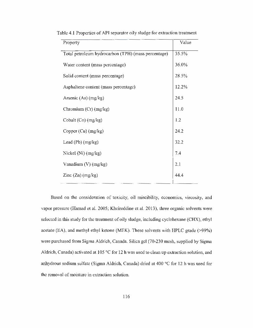
Table 4.1 Properties of API separator oily sludge for extraction treatment
Property Value
Total petroleum hydrocarbon (TPH) (mass percentage) 35.5%
Water content (mass percentage)
Solid content (mass percentage)
Asphaltene content (mass percentage)
Arsenic (As) (mg/kg)
Chromium (Cr) (mg/kg)
Cobalt (Co) (mg/kg)
Copper (Cu) (mg/kg)
Lead (Pb) ( mg/kg)
Nickel (Ni) (mg/kg)
Vanadium (V) (mg/kg)
Zinc (Zn) (mg/kg)
36.0%
28.5%
12.2%
24.5
11.0
1.2
24.2
32.2
7.4
2.1
44.4
Based on the consideration of toxicity, oil miscibility, economics, viscosity, and
vapor pressure (Hamad et al. 2005; Kheireddine et al. 2013), three organic solvents were
selected in this study for the treatment of oily sludge, including cyclohexane (CHX), ethyl
acetate (EA), and methyl ethyl ketone (MEK). These solvents with HPLC grade (>99%)
were purchased from Sigma Aldrich, Canada. Silica gel (70-230 mesh, supplied by Sigma
Aldrich, Canada) activated at 105 °C for 12 h was used to clean up extraction solution, and
anhydrous sodium sulfate (Sigma Aldrich, Canada) dried at 400 °C for 12 h was used for
the removal of moisture in extraction solution.
116
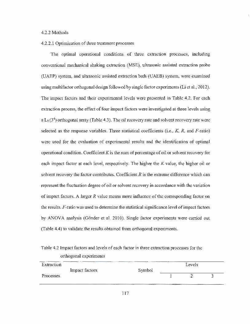
4.2.2 Methods
4.2.2.1 Optimization of three treatment processes
The optimal operational conditions of three extraction processes, including
conventional mechanical shaking extraction (MSE), ultrasonic assisted extraction probe
(UAEP) system, and ultrasonic assisted extraction bath (UAEB) system, were examined
using multifactor orthogonal design followed by single factor experiments (Li et al. , 2012).
The impact factors and their experimental levels were presented in Table 4.2. For each
extraction process, the effect of four impact factors were investigated at three levels using
a L9 (34) orthogonal array (Table 4.3). The oil recovery rate and solvent recovery rate were
selected as the response variables. Three statistical coefficients (i.e., K, R, and F-ratio)
were used for the evaluation of experimental results and the identification of optimal
operational condition. Coefficient K is the sum of percentage of oil or solvent recovery for
each impact factor at each level, respectively. The higher the K value, the higher oil or
solvent recovery the factor contributes. Coefficient R is the extreme difference which can
represent the fluctuation degree of oil or solvent recovery in accordance with the variation
of impact factors. A larger R value means more influence of the corresponding factor on
the results. F-ratio was used to determine the statistical significance level of impact factors
by ANOVA analysis (Gonder et al. 2010). Single factor experiments were carried out
(Table 4.4) to validate the results obtained from orthogonal experiments.
Table 4.2 Impact factors and levels of each factor in three extraction processes for the
orthogonal experiments
Extraction Levels Impact factors Symbol
Processes 1 2
117
3
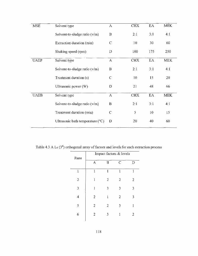
MSE Solvent type A CHX EA MEK
Solvent-to-sludge ratio (v/m) B 2: 1 3:1 4:1
Extraction duration (min) C 10 30 60
Shaking speed (rpm) D 100 175 250
UAEP Solvent type A CHX EA MEK
Solvent-to-sludge ratio (v/m) B 2:1 3: 1 4:1
Treatment duration (s) C 10 15 20
Ultrasonic power (W) D 21 48 66
UAEB Solvent type A CHX EA MEK
Solvent-to-sludge ratio (v/m) B 2: l 3:1 4:1
Treatment duration (min) C 5 10 15
Ultrasonic bath temperature (0 C) D 20 40 60
Table 4.3 A L9 (34) orthogonal array of factors and levels for each extraction process
Impact factors & levels Runs
A B C D
1 1 1 1 1
2 1 2 2 2
3 1 3 3 3
4 2 1 2 3
5 2 2 3 1
6 2 3 1 2
118
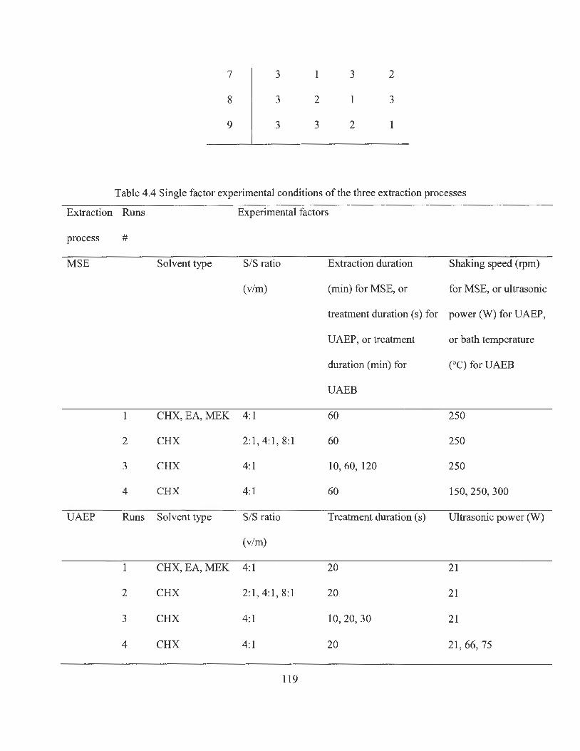
Extraction
process
MSE
UAEP
7
8
9
3
3
3
1
2
3
3
2
2
3
1
Table 4.4 Single factor experimental conditions of the three extraction processes
Runs Experimental factors
#
Solvent type S/S ratio Extraction duration Shaking speed (rpm)
(v/m) (min) for MSE, or for MSE, or ultrasonic
treatment duration ( s) for power (W) for UAEP,
UAEP, or treatment or bath temperature
duration (min) for (°C) for UAEB
UAEB
1 CHX, EA, MEK 4:1 60 250
2 CHX 2:1, 4:1 , 8:1 60 250
3 CHX 4:1 10, 60, 120 250
4 CHX 4:1 60 150, 250, 300
Runs Solvent type S/S ratio Treatment duration ( s) Ultrasonic power (W)
(v/m)
1 CHX, EA, MEK 4:1 20 21
2 CHX 2:1 , 4:1 , 8:1 20 21
3 CHX 4:1 10,20, 30 21
4 CHX 4:1 20 21,66, 75
119
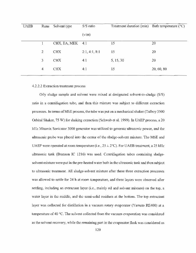
UAEB Runs Solvent type S/S ratio Treatment duration (min) Bath temperature (0 C)
(v/m)
1 CHX,EA,MEK 4:1 15 20
2 CHX 2:1, 4:1, 8:1 15 20
3 CHX 4:1 5, 15, 30 20
4 CHX 4:1 15 20,60,80
4.2.2.2 Extraction treatment process
Oily sludge sample and solvent were mixed at designated solvent-to-sludge (S/S)
ratio in a centrifugation tube, and then this mixture was subject to different extraction
processes. In terms ofMSE process, the tube was put on a mechanical shaker (Talboy 3500
Orbital Shaker, 75 W) for shaking extraction (Schwab et al. 1999). In UAEP process, a 20
kHz Misonix Sonicator 3000 generator was utilized to generate ultrasonic power, and the
ultrasonic probe was placed into the center of the sludge-solvent mixture. The MSE and
UAEP were operated at room temperature (i.e., 25 ± 2°C). For UAEB treatment, a 25 kHz
ultrasonic tank (Branson IC 1216) was used. Centrifugation tubes containing sludge-
solvent mixture were put in the pre-heated water bath in the ultrasonic tank and then subject
to ultrasonic treatment. All sludge-solvent mixture after these three extraction processes
was allowed to settle for 24 h at room temperature, and three layers were observed after
settling, including an extractant layer (i.e., mainly oil and solvent mixture) on the top, a
water layer in the middle, and the semi-solid residues at the bottom. The top extractant
layer was collected for distillation in a vacuum rotary evaporator (Yamato RE400) at a
temperature of 40 °C. The solvent collected from the vacuum evaporation was considered
as the solvent recovery, while the remaining part in the evaporator flask was considered as
120
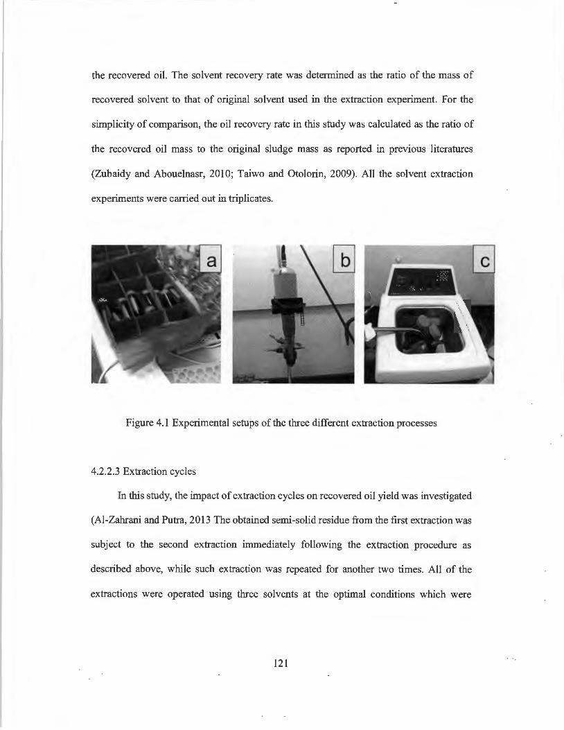
the recovered oil. The solvent recovery rate was determined as the ratio of the mass of
recovered solvent to that of original solvent used in the extraction experiment. For the
simplicity of comparison, the oil recovery rate in this study was calculated as the ratio of
the recovered oil mass to the original sludge mass as reported in previous literatures
(Zubaidy and Abouelnasr, 2010; Taiwo and Otolorin, 2009). All the solvent extraction
experiments were carried out in triplicates.
Figure 4.1 Experimental setups of the three different extraction processes
4.2.2.3 Extraction cycles
In this study, the impact of extraction cycles on recovered oil yield was investigated
(Al-Zahrani and Putra, 2013 The obtained semi-solid residue from the first extraction was
subject to the second extraction immediately following the extraction procedure as
described above, while such extraction was repeated for another two times. All of the
extractions were operated using three solvents at the optimal conditions which were
121
identified from section 2.2.1. The oil recovery rate of the ith ( ORi) extraction was calculated
based on the mass of recovered oil from the ith extraction (Xi):
ORi (%) = L~Xi x 100 s
(4.1)
Where Ms is the mass of original oily sludge samples.
4.2.2.4 Sample analysis
The recovered oil from different treatments was purified to remove water, particles,
and unwanted polar organic compounds by column cleanup (CCME, 2001). About 1.5 g
of recovered oil was completely dissolved in 20 mL of solvent (i.e., 1: 1
cyclohexane/dichloromethane) and passed through the column packed with silica gel and
anhydrous sodium sulfate. After column cleanup, the oil sample was sent for vacuum
evaporation. After evaporation, the final leftover was weighed as relatively pure PHCs
(Zhang et al. 2012), and the TPH content was calculated as the mass percentage of PH Cs
in recovered oil. The distribution of PH Cs fractions (F2, F3 and F4) in the recovered oil
by different extraction processes was also analyzed. The fractions of F2, F3 and F4 were
defined as the group of petroleum hydrocarbons from C10 to C16, C16 to C34, and C34 to Cso,
respectively (CCME, 2011). The analysis was conducted using a Varian CP-3800 Gas
Chromatograph with flame ionization detector (GC-FID) following the CCME standard
method (CCME 2001). The physical properties and heavy metals in recovered oil were
analyzed according to ASTM methods as described in section 2.1.
122
4.3 Results and discussion
4. 3 .1 The effect of mechanical shaking extraction (MSE)
Figure 4.2a presents the effects of four impact factors on oil recovery from MSE
treatment. It can be seen that all three solvents were effective on oil recovery from oily
sludge. CHX can recover more than 50% of oil from oily sludge, followed by EA (i.e.,
37.9%) and MEK (i.e., 33 .3%). The amount of recovered oil by CHX was much higher
than the TPH content in original oily sludge (Table 4.1). This is because the recovered oil
by CHX contained a considerable amount of impurities such as water and solid particles,
and thus the calculated oil recovery of CHX extraction was higher than the those of EA
and MEK extractions. It was reported that CHX can be an effective solvent for oily sludge
treatment since it has high affinity with various petroleum constituents in oily sludge
compared with other solvents (Taiwo and Otolorin 2009; Liang et al. 2014). Other factors
such (SIS ratio, extraction duration, and shaking speed) also affect oily recovery.
Particularly, solvent type illustrated the most significant influence on oil recovery,
followed by shaking speed, extraction duration, and SIS ratio according to the order of Rj
value (Table 4.5). The highest oil recovery was observed as 63. 7% in CHX extraction with
the SIS ratio of 4: 1, extraction duration of 60 min, and shaking speed of 250 rpm,
respectively. According to the ANOV A analysis shown in Table 4.6, the effects of four
impact factors on oil recovery were significant. It is widely reported that high SIS ratio
could be beneficial to solvent extraction treatment of tank bottom sludge (Zubaidy and
Abouelnasr, 2010) and used lubricating oil (Al-Zahrani and Putra, 2013; Rincon et al.
2005). This is because the increase in the ratio of SIS can enhance the mutual solubility of
oil in solvent, thereby increasing the amount of oil recovered (Al-Zahrani and Putra, 2013).
Longer extraction time is also preferred since it allows sufficient contact time for oil and
123
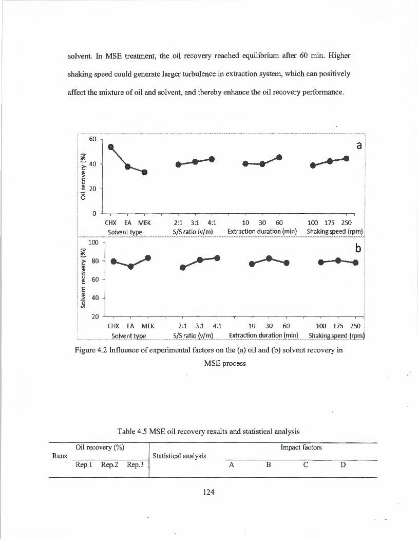
Runs
solvent. In MSE treatment, the oil recovery reached equilibrium after 60 min. Higher
shaking speed could generate larger turbulence in extraction system, which can positively
affect the mixture of oil and solvent, and thereby enhance the oil recovery performance.
60
'i: I; 40 (I)
I :> 0 . u I~ 20
.. . a ,
CHX EA MEK Solvent type
2:1 3:1 4:1 S/S ratio (v/rn)
10 30 60 Extraction duration (min)
100 175 250 Shaking speed (rpm)
I 100 1 'i:
Ii 80
, U 60 - ~ I +-'
I] 40 I~ I 20
I l
CHX EA MEK Solvent type
- --
2:1 3:1 4:1 10 30 60 100 175 250 S/S ratio (v/ml_ Extraction duration (min) . . Shaking~~ed (q~mj
Figure 4.2 Influence of experimental factors on the (a) oil and (b) solvent recovery in
MSE process
Table 4.5 MSE oil recovery results and statistical analysis
Oil recovery(%) Impact factors ------------. Statistical analysis
Rep. I Rep.2 Rep.3 A B C D
124

46. 7 48 .9 45 .1 K11 483.0 354.6 360.6 347.2
2 46.1 53.2 57.1 K21 340.6 374.8 356.3 378.5
3 59.5 63.7 62.7 KJJ 299.7 394.0 406.5 397.6
4 36.0 36.3 36.4 ka J 9 9 9 9
5 36.1 36.9 42.3 KJ/kJ 53.7 39.4 40.1 38.6
6 38 .5 39.5 38.8 K2/kJ 37.8 41.6 39.6 42.1
7 35.5 34.8 35.1 KJ/kJ 33.3 43.8 45.6 44.2
8 32.6 32.4 38.1 R1 20.4 4.4 5.6 5.6
9 33.5 29.0 28.8 Order A>D>C>B
Optimal level 3 3 3
Optimal organization A1D3C3B3
a The number of the appearance for a specific level
Table 4.6 ANOV A for oil and solvent recovery results from MSE
Oil recovery: Sources of variation ss a df b MS C Fvalue Fa.d Significance e
(A) Solvent type 2056.7 2 1028.4 134.4 F oos(2,18) = 3.6 **
(B) SIS ratio (vim) 86.3 2 43 .1 5.6 F o.01(2,18) = 6.0 *
(C) Extraction duration (min) 172.0 2 86.0 11.2 **
(D) Shaking speed (rpm) 144.0 2 72.0 9.4 **
Error 137.7 18 7.6
Total 2596.7 26
Solvent recovery: Sources of variation ss df MS F value Fa. Significance
(A) Solvent type 383.7 2 191.9 6.6 F oos(2,18) = 3.6 **
(B) SIS ratio (vim) 535.7 2 267.8 9.3 F o.01(2,18) = 6.0 **
125
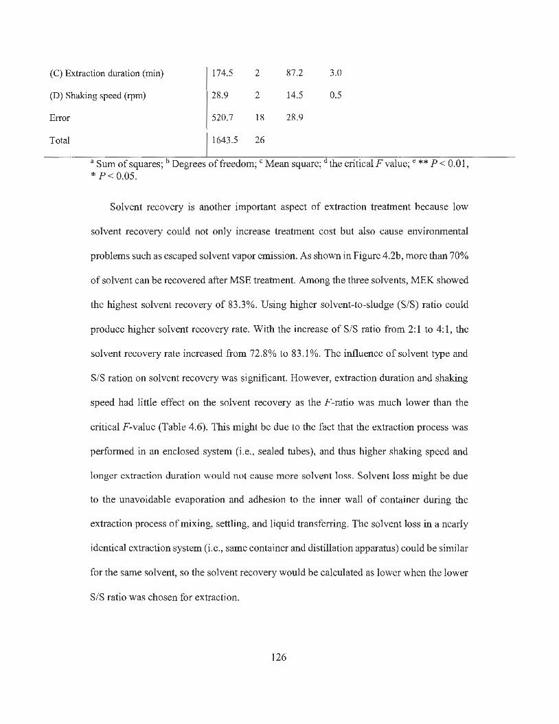
(C) Extraction duration (min) 174.5 2 87.2 3.0
(D) Shaking speed (rpm) 28 .9 2 14.5 0.5
Error
Total
520.7 18 28.9
1643.5 26
a Sum of squares; b Degrees of freedom; c Mean square; d the critical F value; e ** P < 0.01 , * P < 0.05 .
Solvent recovery is another important aspect of extraction treatment because low
solvent recovery could not only increase treatment cost but also cause environmental
problems such as escaped solvent vapor emission. As shown in Figure 4.2b, more than 70%
of solvent can be recovered after MSE treatment. Among the three solvents, MEK showed
the highest solvent recovery of 83.3%. Using higher solvent-to-sludge (S/S) ratio could
produce higher solvent recovery rate. With the increase of S/S ratio from 2: 1 to 4: 1, the
solvent recovery rate increased from 72.8% to 83.1 %. The influence of solvent type and
S/S ration on solvent recovery was significant. However, extraction duration and shaking
speed had little effect on the solvent recovery as the F-ratio was much lower than the
critical F-value (Table 4.6) . This might be due to the fact that the extraction process was
performed in an enclosed system (i.e., sealed tubes), and thus higher shaking speed and
longer extraction duration would not cause more solvent loss. Solvent loss might be due
to the unavoidable evaporation and adhesion to the inner wall of container during the
extraction process of mixing, settling, and liquid transferring. The solvent loss in a nearly
identical extraction system (i.e., same container and distillation apparatus) could be similar
for the same solvent, so the solvent recovery would be calculated as lower when the lower
S/S ratio was chosen for extraction.
126

80
'*- 60 ~ Q) > 0 u 40 Q) ... 0
20
0
The results of single factor MSE experiment (Figure 4.3) indicated that under the
same extraction conditions, the MSE treatment using CHX could achieve higher oil
recovery rate than EA and MEK. There was little difference in oil recovery between the
treatment of EA and MEK. The results also revealed that higher values of S/S ratio,
extraction duration, and shaking speed were preferable for oil recovery. Oil recovery can
reach equilibrium when the S/S ratio, extraction duration, and shaking speed reached to
4: 1, 60 min, and 250 rpm, respectively. Further increase the value of these factors only
brought limited enhancement, but could increase the cost and duration of treatment.
Therefore, it is reasonable to set the optimal MSE condition as S/S ratio of 4: 1, extraction
duration of 60 min, and shaking speed of 250 rpm for economical consideration.
- ~ ~ CHX EA MEK
Solvent type
2:1 4:1 8:1 S/S ratio (v/m)
--10 60 120
Extraction duration (min)
Figure 4.3 Results of single-factor experiments ofMSE
127
150 250 300 Shaking speed (rpm)

4.3.2 Ultrasonic assisted extraction using a probe system (UAEP)
Figure 4.4a presents the effects of four experimental factors on UAEP performance.
Similar to MSE process, CHX showed much higher oil recovery than the other two
solvents. Oil recovery of UAEP increased with S/S ratio, treatment duration and ultrasonic
power. It is noteworthy that the highest oil recovery obtained by CHX was 59.8% in UAEP,
which is higher than the highest oil recovery of 53.7% in MSE by the same solvent. The
extraction using MEK was also improved by UAEP with the highest oil recovery of38.3%
compared to 33 .3% by using MSE. According to the Rj value shown inin Table 4.7, the
influence of four factors on oil recovery was ranked in the order of solvent type, S/S ratio,
treatment duration, and ultrasonic power. Among these four factors, ultrasonic power
showed insignificant effect on oil recovery while the effects of other three factors were
significant (Table 4.8), indicating that the ultrasonic power of 21 W was sufficient to
generate enough agitation for the mixing of oil and solvents. As compared to the longer
extraction duration required by MSE, the UAEP can achieve satisfactory performance
within a very short duration (i.e. in seconds).
128
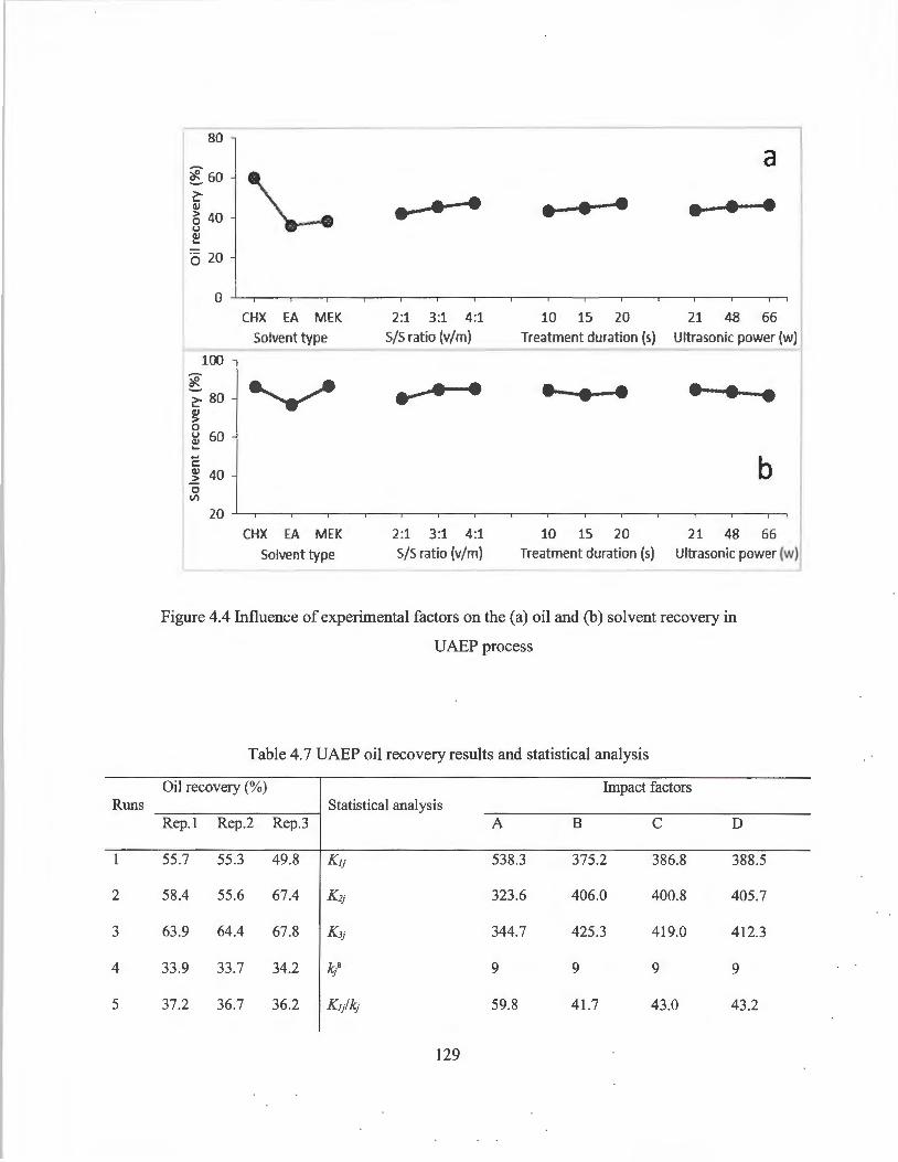
Runs
1
2
3
4
5
1 80 ' 1~60 ~ (lJ
: ~ 40 · U I ~ I Q 20
r 100 ~ i 80
I~ :rl 60 ... ... 11 40 . V'l
CHX EA MEK Solvent type
..-• •
2:1 3:1 4:1 5/S ratio (v/m)
2:1 3:1 4:1 S/S ratio (v/m)
• • •
10 15 20 Treatment duration (s)
a
• • •
21 48 66 Ultrasonic power (w)
b
10 15 20 21 48 66 Treatment duration (s) Ultraso~ic power (w~
Figure 4.4 Influence of experimental factors on the (a) oil and (b) solvent recovery in
UAEP process
Table 4. 7 UAEP oil recovery results and statistical analysis
Oil recovery(%) Impact factors Statistical analysis
Rep.I Rep.2 Rep.3 A B C D
55.7 55.3 49.8 K11 538.3 375.2 386.8 388.5
58.4 55.6 67.4 K21 323.6 406.0 400.8 405.7
63.9 64.4 67.8 K11 344.7 425.3 419.0 412.3
33.9 33.7 34.2 k·" 1 9 9 9 9
37.2 36.7 36.2 K1/"1 59.8 41.7 43 .0 43.2
129

6 36.1 37.5 38.0 Ki/"1· 36.0 45.1 44.5 45.1
7 37.1 38.1 37.5 KJ/"1· 38.3 47.3 46.5 45.8
8 38.4 38.7 37.3 R1 23.9 5.6 3.6 2.6
9 36.5 37.8 43.2 Order A>B>C>D
Optimal level 3 3 3
Optimal organization A1B3C3D3
a The number of the appearance for a specific level
Table 4.8 ANOVA for oil and solvent recovery results from UAEP
Oil recovery: Sources of variation ssa df b MSC Fvalue Fad Significance e
(A) Solvent type 3112.8 2 1556.4 206.6 Foos(2,18) = 3.6 ** (B) S/S ratio (v/m) 141.6 2 70.8 9.4 Foo1(2,18) = 6.0 ** (C) Extraction duration (s) 57.7 2 28.8 3.8 * (D) Ultrasonic power (W) 33.4 2 16.7 2.2
Error 135.6 18 7.5
Total 3481.1 26
Solvent recovery: Sources of variation ss df MS Fvalue Fa Significance
(A) Solvent type 548.5 2 274.2 24.0 Foos(2,18) = 3.6 ** (B) S/S ratio (v/m) 148.6 2 74.3 6.5 Fo.01(2,18) = 6.0 ** (C) Extraction duration (s) 25 .0 2 12.5 1.1
(D) Ultrasonic power (W) 44.4 2 22.2 1.9
Error 206.0 18 11.4
Total 972.4 26
a Sum of squares; b Degrees of freedom; c Mean square; ct the critical F value; e ** P < 0.01, * P< 0.05.
130
The effects of the experimental factors on solvent recovery are shown in Figure 4.4b.
It can be seen that more than 80% of CHX and MEK can be recovered after UAEP
treatment, while a lower recovery rate (i.e. , 76.7%) was observed for EA. Higher S/S ratio
was beneficial to the solvent recovery. For example, the solvent recovery increased from
79.8% to 84.8% as the S/S ratio increased from 2: 1 to 4: 1. Similar to MSE, the solvent
type and S/S ratio showed significant effect on solvent recovery in UAEP treatment (Table
4.8). Moreover, longer treatment duration and higher ultrasonic power showed
insignificant effects on solvent recovery (Table 4.8). The results indicate that UAEP would
not cause negative influence on solvent recovery by noting the higher solvent recovery
than MSE treatment.
The results of single factor experiments ofUAEP are illustrated in Figure 4.5. Under
the same condition, CHX can recover as high as 68.8% of oil from oily sludge, while EA
and MEK achieved an oil recovery of 35.0% and 37.2%, respectively. The extraction
performance can be significantly improved (p<0.05) by UAEP using CHX and MEK with
about 8% (CHX) and 3% (MEK) increment in oil recovery as compared to the highest oil
recovery obtained in MSE by the same solvent. However, little difference (p>0.05) was
observed between UAEP and MSE treatments when using EA as the extraction solvent.
Similar to MSE, a promising oil recovery can be obtained when the S/S ratio reached 4: 1
in UAEP, and further increase S/S ratio lead to no improvement in oil recovery. The oil
recovery rate was also increased from 55. 7% to 68.4% as treatment duration extended from
10 s to 20 s, but there is no need to further extend the treatment duration because increasing
duration from 20 s to 3 0 s brought no obvious increase in oil recovery. In fact, longer
treatment duration might cause higher amount of solvent loss and energy consumption.
131
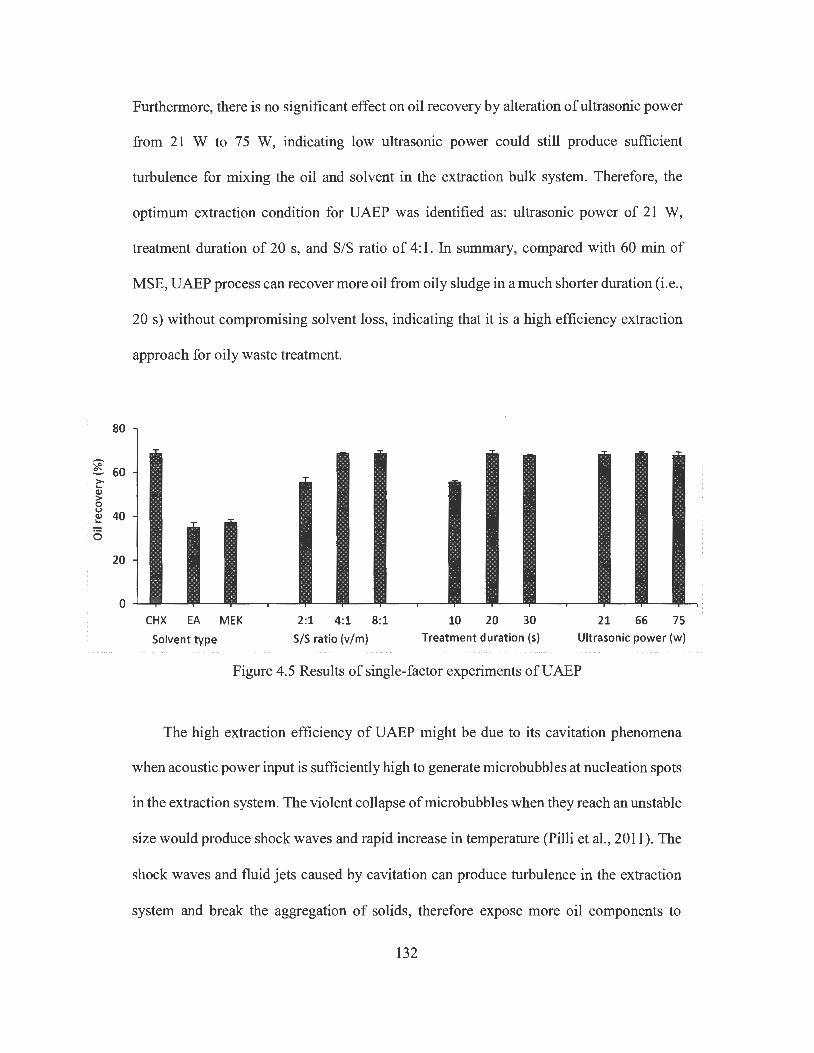
80
~ 60 c:-C1J > 0 u 40 C1J ... 0
20
0
Furthermore, there is no significant effect on oil recovery by alteration of ultrasonic power
from 21 W to 75 W, indicating low ultrasonic power could still produce sufficient
turbulence for mixing the oil and solvent in the extraction bulk system. Therefore, the
optimum extraction condition for UAEP was identified as: ultrasonic power of 21 W,
treatment duration of 20 s, and S/S ratio of 4: 1. In summary, compared with 60 min of
MSE, UAEP process can recover more oil from oily sludge in a much shorter duration (i.e.,
20 s) without compromising solvent loss, indicating that it is a high efficiency extraction
approach for oily waste treatment.
- - -CHX EA MEK
Solvent type
2:1 4:1 8:1 S/S ratio (v/m)
10 20 30 21 66 75 Treatment duration (s) Ultrasonic power (w)
Figure 4.5 Results of single-factor experiments ofUAEP
The high extraction efficiency of UAEP might be due to its cavitation phenomena
when acoustic power input is sufficiently high to generate microbubbles at nucleation spots
in the extraction system. The violent collapse of microbubbles when they reach an unstable
size would produce shock waves and rapid increase in temperature (Pilli et al., 2011). The
shock waves and fluid jets caused by cavitation can produce turbulence in the extraction
system and break the aggregation of solids, therefore expose more oil components to
132
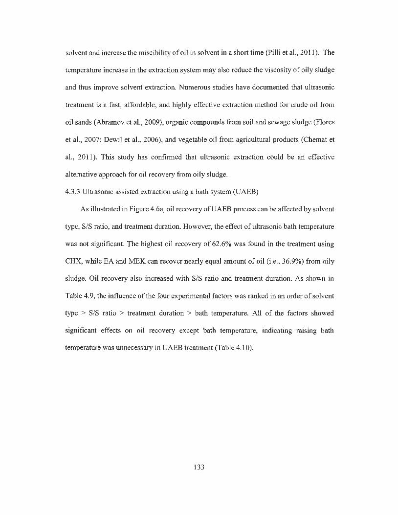
solvent and increase the miscibility of oil in solvent in a short time (Pilli et al., 2011 ). The
temperature increase in the extraction system may also reduce the viscosity of oily sludge
and thus improve solvent extraction. Numerous studies have documented that ultrasonic
treatment is a fast, affordable, and highly effective extraction method for crude oil from
oil sands (Abramov et al. , 2009), organic compounds from soil and sewage sludge (Flores
et al., 2007; Dewil et al., 2006), and vegetable oil from agricultural products (Chemat et
al., 2011). This study has confirmed that ultrasonic extraction could be an effective
alternative approach for oil recovery from oily sludge.
4.3.3 Ultrasonic assisted extraction using a bath system (UAEB)
As illustrated in Figure 4.6a, oil recovery ofUAEB process can be affected by solvent
type, S/S ratio, and treatment duration. However, the effect of ultrasonic bath temperature
was not significant. The highest oil recovery of 62.6% was found in the treatment using
CHX, while EA and MEK can recover nearly equal amount of oil (i.e., 36.9%) from oily
sludge. Oil recovery also increased with S/S ratio and treatment duration. As shown in
Table 4.9, the influence of the four experimental factors was ranked in an order of solvent
type > SIS ratio > treatment duration > bath temperature. All of the factors showed
significant effects on oil recovery except bath temperature, indicating raising bath
temperature was unnecessary in UAEB treatment (Table 4.10).
133
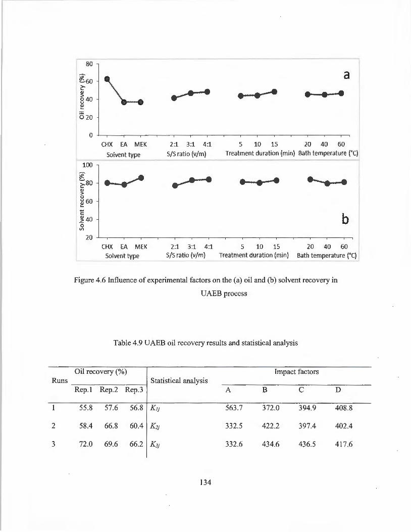
Runs
1
2
3
,--- - - -80
e6o \._. a
I ~ I Q.J • • • ~40
1@20 I
0 CHX EA MEK 2:1 3:1 4:1 5 10 15 20 40 60
Solvent type S/S ratio {v/m) Treatment duration (min) Bath temperature (0() - """'- - - --,
100
* ~ ... ·-so • • If I ~ 60 ... ....
1140 b
l 20
CHX EA MEK 2:1 3:1 4:1 5 10 15 20 40 60 Solvent type S/S ratio (v/m) Treatment duration (min) Bath temperature (0
()
- - - ---'
Figure 4.6 Influence of experimental factors on the (a) oil and (b) solvent recovery in
UAEB process
Table 4.9 UAEB oil recovery results and statistical analysis
Oil recovery (%) Impact factors Statistical analysis
Rep.I Rep.2 Rep.3 A B C D
55.8 57.6 56.8 KJJ 563.7 372.0 394.9 408.8
58.4 66.8 60.4 K2j 332.5 422.2 397.4 402.4
72.0 69.6 66.2 K3j 332.6 434.6 436.5 417.6
134
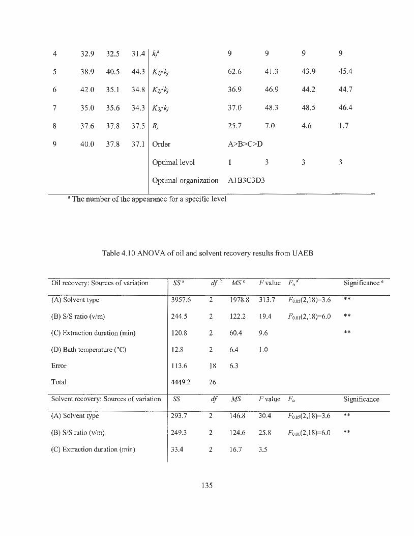
4 32.9 32.5 31.4 kl 9 9 9 9
5 38.9 40.5 44.3 K1/ k1 62.6 41.3 43.9 45.4
6 42.0 35.1 34.8 K2/'9 36.9 46.9 44.2 44.7
7 35.0 35.6 34.3 K3/'9 37.0 48.3 48.5 46.4
8 37.6 37.8 37.5 RJ 25.7 7.0 4.6 1.7
9 40.0 37.8 37.1 Order A>B>C>D
Optimal level 1 3 3 3
Optimal organization A1B3C3D3
a The number of the appearance for a specific level
Table 4.10 ANOV A of oil and solvent recovery results from UAEB
Oil recovery: Sources of variation ss• df b MS C Fvalue Fad Significance e
(A) Solvent type 3957.6 2 1978.8 313.7 Fo.os(2, 18)=3.6 **
(B) S/S ratio (v/m) 244.5 2 122.2 19.4 F o.0 1(2,18)=6.0 **
(C) Extraction duration (min) 120.8 2 60.4 9.6 **
(D) Bath temperature (°C) 12.8 2 6.4 1.0
Error 113.6 18 6.3
Total 4449.2 26
Solvent recovery: Sources of variation ss df MS Fvalue Fa Significance
(A) Solvent type 293.7 2 146.8 30.4 Foos(2,18)=3.6 **
(B) S/S ratio (v/m) 249.3 2 124.6 25.8 Fo.o, (2, 18)=6.0 **
(C) Extraction duration (min) 33.4 2 16.7 3.5
135

(D) Bath temperature (0 C) 92.6
87.0
755 .9
2
18
26
46.3
4.8
9.6 ** Error
Total
a Sum of squares; b Degrees of freedom; c Mean square; d the critical F value; e ** P <
0.01, * P < 0.05.
The effects of the experimental factors on solvent recovery from UAEB are shown in
Figure 4.6b. Compared to CHX and EA, MEK showed higher solvent recovery
performance. Similar to MSE and UAEP, the solvent recovery was improved as more
solvent was used for extraction. There was no obvious variation in solvent recovery as the
treatment duration extended from 5 to 15 min, but bath temperature showed a negative
effect on solvent recovery for the reason that solvent recovery declined by about 4% as the
bath temperature increased from 20 to 60 °C.
The results of single-factor experiments are shown in Figure 4. 7. The oil recovery of
CHX, EA, and MEK in UAEB treatment was 67.6%, 35.0%, and 34.7%, respectively.
There was no significant difference in oil recovery between UAEP and UAEB treatment
when the same solvent was applied, but the oil recovery of UAEP and UAEB were
significantly higher than that of MSE treatment using the same solvent. The oil recovery
increased from 56.3% to 67.3% as the SIS ratio changed from 2:1 to 4:1, but only a trivial
increment in oil recovery was observed when this ratio further increased from 4: 1 to 8: 1.
The variation of oil recovery caused by the extension of ultrasonic treatment duration also
showed similar trends. A significant increase in oil recovery was obtained as treatment
duration increased from 5 to 15 min, but little enhancement was observed when the
treatment duration exceeded 15 min. In agreement with the results from orthogonal
136

experiments, the bath temperature of UAEB process had limited effect on oil recovery.
Therefore, the optimum condition for UAEB treatment was set as: S/S ratio of 4: 1,
treatment duration of 15 min, and bath temperature of 20 °C.
The results indicated that in comparison to MSE, UAEB can obtain a relatively higher
oil recovery within shorter treatment duration. The oil recovery of UAEB and UAEP by
three solvents under each optimal condition was similar, but longer treatment duration (i.e.,
20 s of UAEP as compared to 15 min of UAEB) and higher energy consumption (i.e. 21
W of UAEP as compared to 80 W of UAEB) was required by UAEB treatment. For
example, the total energy consumption of each treatment by UAEP, UAEB, and MSE
processes were 1.17x 1 o-4, 0.02, and 4.5 KWh, respectively. Higher energy consumption
in UAEB process might be due to the fact that UAEP treatment is a much more powerful
process because the ultrasonic energy is delivered on a small area around the ultrasonic
probe, but ultrasonic energy can be highly attenuated by the water contained in the bath
and the walls of the container used in UAEB treatment (Chemat et al. 2011). As a result, a
higher ultrasonic power and longer extraction duration are required by UAEB to achieve
satisfactory extraction performance. Nevertheless, UAEB process can handle a much
larger volume of oily sludge than UAEP in one treatment, and thus it has great potential to
be applied to large-scale treatment. Many safety, equipment design, and treatment cost
issues should be thoroughly considered before introducing UAE process to large-scale oily
sludge treatment. For example, the safety concerns may include but not limited to the
escaping emission of solvent vapor, the corrosion of pipelines caused by water in oily
sludge, and the heat and pressure generated during distillation. Treatment cost also should
be carefully calculated in terms of the loss of solvent by evaporation and/or leaking, energy
137
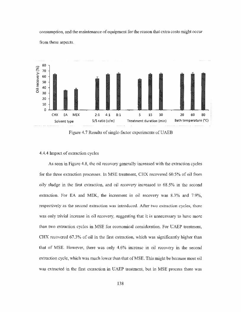
consumption, and the maintenance of equipment for the reason that extra costs might occur
from these aspects.
l 80 70
~ 60 QJ > 0 u Q) .... 0
so 40 30 20 10
0 - ~ ~ CHX EA MEK
Solvent type
2:1 4:1 8:1 S/S ratio (v/m)
5 15 30 Treatment duration (min)
Figure 4.7 Results of single-factor experiments ofUAEB
4.4.4 Impact of extraction cycles
--20 60 80
Bath temperature (0 C)
As seen in Figure 4.8, the oil recovery generally increased with the extraction cycles
for the three extraction processes. In MSE treatment, CHX recovered 60.5% of oil from
oily sludge in the first extraction, and oil recovery increased to 68.5% in the second
extraction. For EA and MEK, the increment in oil recovery was 8.3% and 7.9%,
respectively as the second extraction was introduced. After two extraction cycles, there
was only trivial increase in oil recovery, suggesting that it is unnecessary to have more
than two extraction cycles in MSE for economical consideration. For UAEP treatment,
CHX recovered 67.3% of oil in the first extraction, which was significantly higher than
that of MSE. However, there was only 4.6% increase in oil recovery in the second
extraction cycle, which was much lower than that ofMSE. This might be because most oil
was extracted in the first extraction in UAEP treatment, but in MSE process there was
138

some oil still trapped in oily sludge after the first extraction. The trapped oil can be
extracted in the second extraction, so that a relatively larger increase in oil recovery can
be observed in MSE. The effect of extraction cycles on oil recovery ofUAEB was similar
to that of UAEP. After the second extraction, the oil recovery of CHX, EA, and MEK in
UAEB increased by 4.4%, 6.6%, and 5.9%, respectively. The results indicate that two
extraction cycles could be sufficient for all treatment processes to achieve a satisfactory
oil recovery.
139

r- 80
I 'ii 60 c:-(J) > 40 0 u (J) L.
0 20
O CHX O EA A MEK
0 1 2 3 4
Number of cycles 80
b0- e e E) 'cf.
60 c:-(J) > A 0 0 i u 40 (J) 4fs ... 0
20 O CHX ¢ EA ti MEK
0 1 2 3 4
Number of cycles 80
l C e e E)
60 er-->-... (J) > 0 u 40 Q.I ... 6
20 O CHX ~ EA li MEK
0 1 2 3 4
Number of cycles
Figure 4.8 Effect of extraction cycles on oil recovery in (a) MSE, (b) UAEP, and (c)
UAEB treatment
140
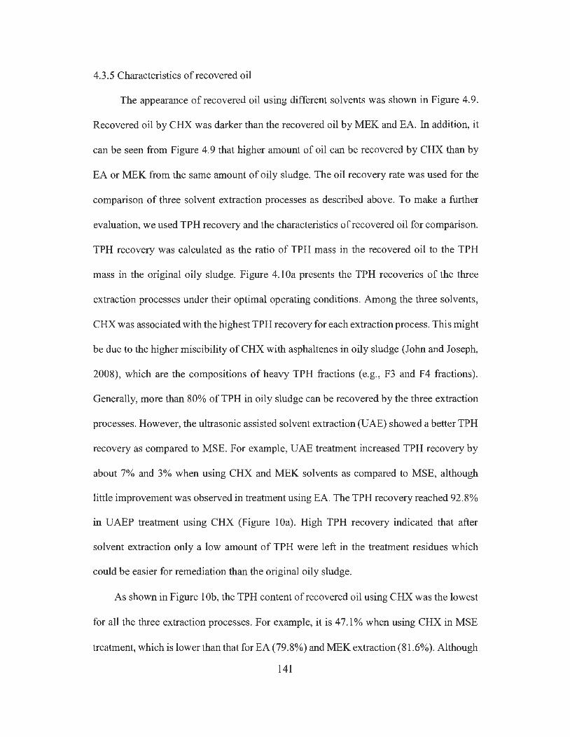
4.3 .5 Characteristics of recovered oil
The appearance of recovered oil using different solvents was shown in Figure 4.9.
Recovered oil by CHX was darker than the recovered oil by MEK and EA. In addition, it
can be seen from Figure 4.9 that higher amount of oil can be recovered by CHX than by
EA or MEK from the same amount of oily sludge. The oil recovery rate was used for the
comparison of three solvent extraction processes as described above. To make a further
evaluation, we used TPH recovery and the characteristics of recovered oil for comparison.
TPH recovery was calculated as the ratio of TPH mass in the recovered oil to the TPH
mass in the original oily sludge. Figure 4.1 Oa presents the TPH recoveries of the three
extraction processes under their optimal operating conditions. Among the three solvents,
CHX was associated with the highest TPH recovery for each extraction process. This might
be due to the higher miscibility of CHX with asphaltenes in oily sludge (John and Joseph,
2008), which are the compositions of heavy TPH fractions (e.g. , F3 and F4 fractions) .
Generally, more than 80% of TPH in oily sludge can be recovered by the three extraction
processes. However, the ultrasonic assisted solvent extraction (UAE) showed a better TPH
recovery as compared to MSE. For example, UAE treatment increased TPH recovery by
about 7% and 3% when using CHX and MEK solvents as compared to MSE, although
little improvement was observed in treatment using EA. The TPH recovery reached 92.8%
in UAEP treatment using CHX (Figure 10a). High TPH recovery indicated that after
solvent extraction only a low amount of TPH were left in the treatment residues which
could be easier for remediation than the original oily sludge.
As shown in Figure 1 Ob, the TPH content of recovered oil using CHX was the lowest
for all the three extraction processes. For example, it is 47.1 % when using CHX in MSE
treatment, which is lower than that for EA (79. 8%) and MEK extraction (81.6% ). Although
141

CHX showed the highest oil and TPH recovery in all the three extraction processes, the
recovered oil contained less valuable TPH content, suggesting that the recovered oil by
CHX contained a higher amount of unwanted impurities. The impurities could be remnant
water, natural polar substances and fine solid particles. It has been reported that about 40%
of heptane insoluble asphaltenes in petroleum residua dissolves in CHX (John and Joseph,
2008). Asphaltenes in extractants tend to form asphaltenic colloids because they have a
propensity to aggregate, flocculate, and adsorb onto interfaces of water and fine solid
particles, resulting in those remnant water and fine solid particles which cannot be readily
removed from extractant by gravitational setting (Spiecker et al., 2003). It can be found
from Figure 1 Ob that in general the UAE is associated with a higher TPH in the recovered
oil than MSE. UAEP treatment obtained the highest TPH content ( e.g., 51.6%, 83 .6%, and
85.8% when using CHX, EA, and MEK, respectively), although the TPH content in
recovered oil by UAEB treatment was only slightly higher than that by MSE treatment.
These results indicated that UAE process could improve both the quantity and quality of
recovered oil as compared to MSE.
142

Figure 4.9 Recovered oils by different solvents from UAEP treatment
143
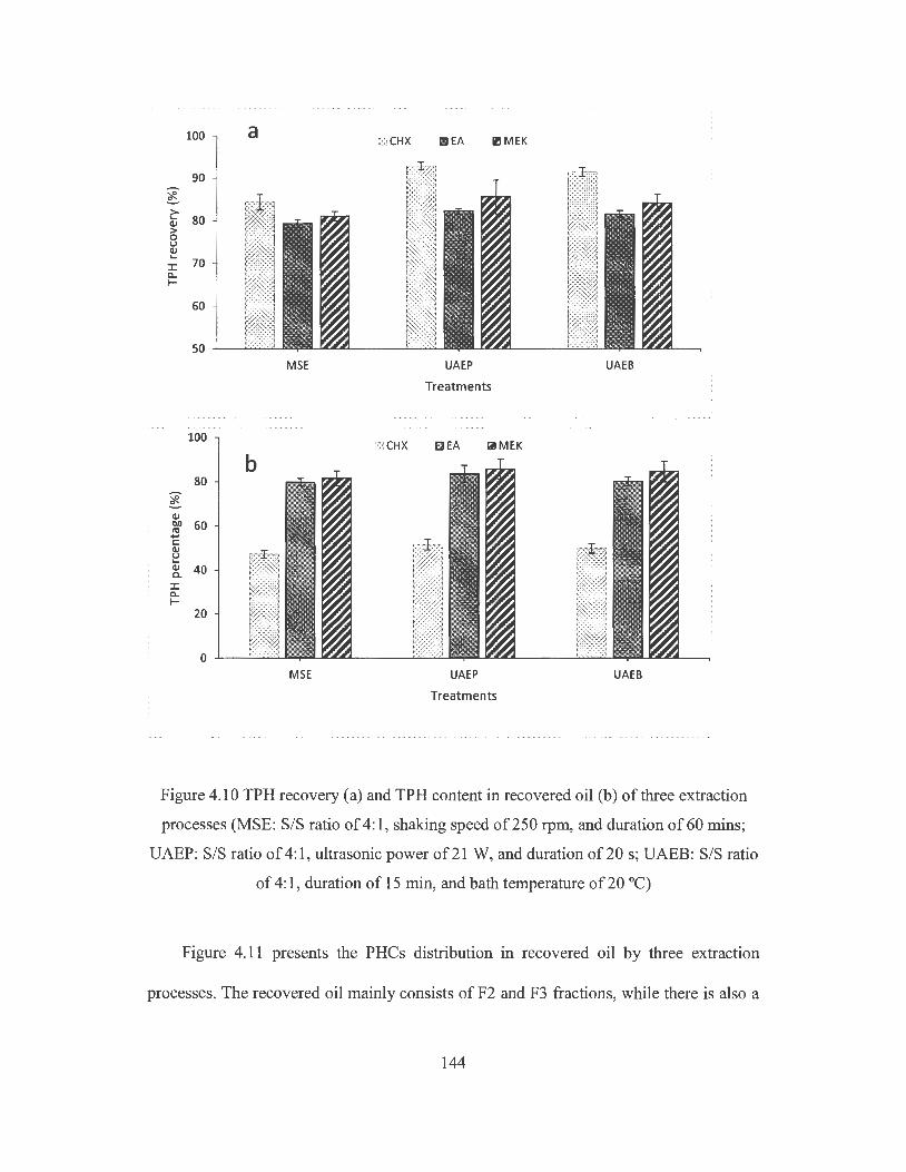
100 a c;J CHX l!!IEA ll!MEK
90
*-c:- 80 C1J > 0 u C1J ... :I: 70 Q.. I-
60
50 MSE UAEP UAEB
Treatments
100 ::;J CHX CEA liii!MEK
80
*-C1J 1:11) 60 ra .... C: C1J
)~~::) u ... C1J 40 a. ~::::::::::::~ :I: ~~~~~~~ Q.. I- ~::~~::::~
20 ~!1!1!1111 f:::::~:::a
YYYYYYYYY-.,",
0 .v":-':.)'.v:'.v':.-;'!
MSE UAEP UAEB
Treatments
Figure 4.10 TPH recovery ( a) and TPH content in recovered oil (b) of three extraction
processes (MSE: SIS ratio of 4: 1, shaking speed of 250 rpm, and duration of 60 mins;
UAEP: SIS ratio of 4: 1, ultrasonic power of 21 W, and duration of 20 s; UAEB: SIS ratio
of 4: 1, duration of 15 min, and bath temperature of 20 °C)
Figure 4.11 presents the PHCs distribution in recovered oil by three extraction
processes. The recovered oil mainly consists of F2 and F3 fractions, while there is also a
144
significant amount of F4 fraction in the recovered oil extracted by CHX, showing that
CHX has better affinity to the heavy PHC components in oily sludge. The PHCs
distribution was similar when the same solvent was utilized, regardless of the extraction
processes. For example, the F3 fraction percentage of recovered oil by EA extraction from
MSE, UAEP, and UAEB were 44.4%, 42.7% and 41.3%, respectively. Zhang et al. (2012)
investigated the individual effect of ultrasonic irradiation on oil recovery from oily sludge,
and found that ultrasonic irradiation alone could not cause significant change of PHCs
distribution in recovered oil. Similar PH Cs distribution in recovered oil of three different
extraction treatments indicates that there was no significant destruction effect on PHCs by
ultrasonic treatment under the experimental conditions in this study.
145

1 60
~ 40 (1) ll.D ro ..... C: Q) 20 u '-Q)
CL.
0
60
~ Q.J 40 ll.D ro ..... C: Q) u '-Q) 20 CL.
0
60
if: 40 Q) ll.D ro ..... C: Q) u 20 '-Q)
CL.
I I
L
CHX
b
'' :
CHX
C
CHX
ml F2 0 F3 ~ F4
EA Solvents
LI F2 D F3 IZI f 4
.·l!
EA Solvents
~ F2 DF3 El:IF4
EA Solvents
MEK
MEK
' l
J MEK
Figure 4.11 Distribution of PH Cs fractions in the recovered oil by using three solvents in
(a) MSE, (b) UAEP, and (c) UAEB (MSE: S/S ratio of 4:1, shaking speed of250 rpm,
146
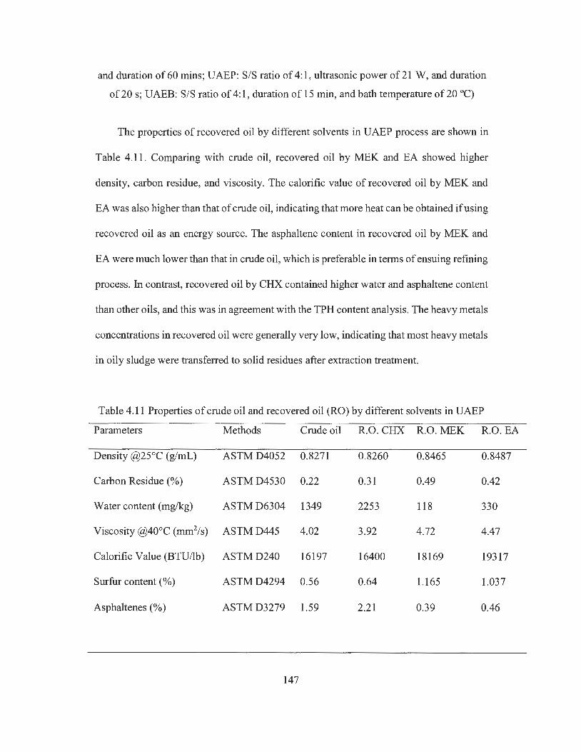
and duration of 60 mins; UAEP: S/S ratio of 4: 1, ultrasonic power of 21 W, and duration
of 20 s; UAEB: S/S ratio of 4: 1, duration of 15 min, and bath temperature of 20 °C)
The properties of recovered oil by different solvents in UAEP process are shown in
Table 4.11. Comparing with crude oil, recovered oil by MEK and EA showed higher
density, carbon residue, and viscosity. The calorific value of recovered oil by MEK and
EA was also higher than that of crude oil, indicating that more heat can be obtained if using
recovered oil as an energy source. The asphaltene content in recovered oil by MEK and
EA were much lower than that in crude oil, which is preferable in terms of ensuing refining
process. In contrast, recovered oil by CHX contained higher water and asphaltene content
than other oils, and this was in agreement with the TPH content analysis. The heavy metals
concentrations in recovered oil were generally very low, indicating that most heavy metals
in oily sludge were transferred to solid residues after extraction treatment.
Table 4.11 Properties of crude oil and recovered oil (RO) by different solvents in UAEP
Parameters Methods Crude oil R.O. CHX R.O.MEK R.O.EA
Density @25°C (g/mL) ASTMD4052 0.8271 0.8260 0.8465 0.8487
Carbon Residue (%) ASTMD4530 0.22 0.31 0.49 0.42
Water content (mg/kg) ASTMD6304 1349 2253 118 330
Viscosity @40°C (mm2/s) ASTMD445 4.02 3.92 4.72 4.47
Calorific Value (BTU/lb) ASTMD240 16197 16400 18169 19317
Surfur content(%) ASTMD4294 0.56 0.64 1.165 1.037
Asphaltenes (%) ASTMD3279 1.59 2.21 0.39 0.46
147
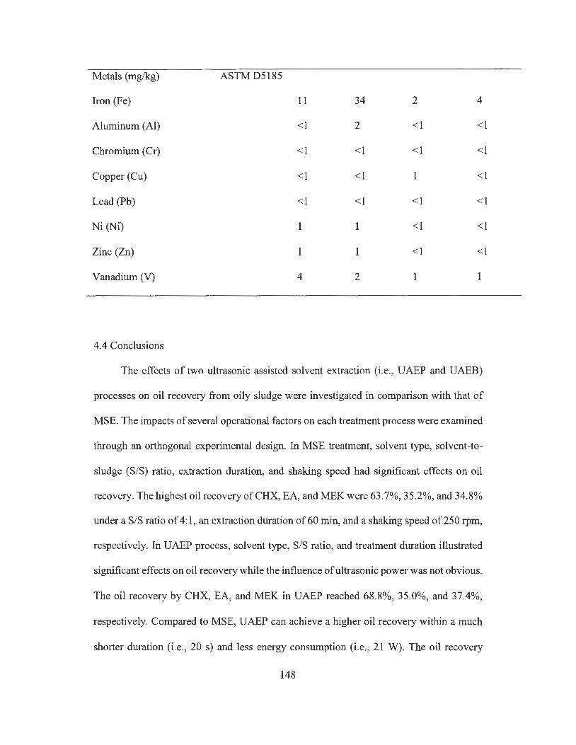
Metals (mg/kg) ASTMD5185
Iron (Fe) 11 34 2 4
Aluminum (Al) <1 2 <1 <1
Chromium (Cr) <1 <1 <1 <1
Copper (Cu) <1 <1 1 <1
Lead (Pb) <1 <1 <1 <1
Ni (Ni) 1 1 <1 <1
Zinc (Zn) 1 < l <1
Vanadium (V) 4 2 1 1
4.4 Conclusions
The effects of two ultrasonic assisted solvent extraction (i.e., UAEP and UAEB)
processes on oil recovery from oily sludge were investigated in comparison with that of
MSE. The impacts of several operational factors on each treatment process were examined
through an orthogonal experimental design. In MSE treatment, solvent type, solvent-to-
sludge (S/S) ratio, extraction duration, and shaking speed had significant effects on oil
recovery. The highest oil recovery ofCHX, EA, and MEK were 63.7%, 35.2%, and 34.8%
under a S/S ratio of 4: 1, an extraction duration of 60 min, and a shaking speed of 250 rpm,
respectively. In UAEP process, solvent type, S/S ratio, and treatment duration illustrated
significant effects on oil recovery while the influence of ultrasonic power was not obvious.
The oil recovery by CHX, EA, and MEK in UAEP reached 68.8%, 35.0%, and 37.4%,
respectively. Compared to MSE, UAEP can achieve a higher oil recovery within a much
shorter duration (i.e., 20 s) and less energy consumption (i.e., 21 W). The oil recovery
148
result of UAEB treatment was also satisfactory as compared to that of MSE, while its
treatment duration (i.e. , 15 min) was shorter than MSE. The results showed that two
extraction cycles could be sufficient to obtain a promising oil recovery in all extraction
treatments, while UAE processes would not cause more solvent loss than MSE treatment.
Among all three solvents, the TPH content in recovered oil using CHX was the lowest (i.e. ,
about 50%), while EA and MEK can recover relatively high TPH content in oil (i.e., >80% ).
The recovered oil mainly consisted ofF2 and F3 fractions, and its physical properties were
similar to those of crude oil, indicating that it can be utilized as a feedstock for downstream
upgrading process. By comprehensively considering the oil recovery, solvent recovery,
TPH recovery, as well as the TPH content and other characteristics of the recovered oil,
the UAE process using MEK would provide promising performance as compared to
conventional MSE process. In summary, UAE could improve both the quantity and quality
of recovered oil from oily sludge within a short treatment duration, and thus it represents
an attractive alternative extraction method for the treatment of refinery oily sludge.
149
Chapter 5 A combination of solvent extraction and freeze thaw for oil recovery from refinery wastewater treatment pond sludge *
* The results ofthis work have been published as: Hu, G.J., Li, J.B., and Hou, H.B., 2015.
A combination of solvent extraction and freeze thaw for oil recovery from petroleum
refinery wastewater treatment pond sludge. Journal o_f Hazardous Materials, 283, 832-840.
5 .1 Introduction
The petrochemical refineries generate a large volume of oily sludge from a wide range
of sources, including crude oil tank bottom sediments, slop oil emulsion solids, residues
from oil/water separators, and dredged sludge from on-site wastewater treatment pond (Hu
et al., 2013). As a very recalcitrant mixture, oily sludge is mainly consisted of water,
petroleum hydrocarbons (PHCs), and solids (Hu et al., 2013; Ramaswamy et al., 2007). It
has been recognized as a hazardous waste in many countries, and its improper management
can adversely impact the environment and public health (Hu et al., 2013; Robertson et al.,
2007; Al-Mutairi et al., 2008). Given the relatively high oil content in sludge, oil recovery
could be the most desirable management option since it can not only generate profit but
also reduce waste volume and pollutant concentration (da Silva et al., 2012; Hu et al., 2013;
Elektorowicz and Habibi, 2005). Driven by increasingly stringent regulations which have
banned the direct land disposal of oily sludge, various physical, chemical, and biological
methods have been developed for its treatment (Hu et al., 2013; da Silva et al., 2012).
Among them, solvent extraction is a simple process by mixing oily waste and solvent in
an appropriate proportion to ensure adequate miscibility of oil in solvent, while most water
and solids are rejected as unwanted impurities which can be removed by gravitational
settling or centrifugation. The oil and solvent mixture (i.e. extractant) can then be separated
150
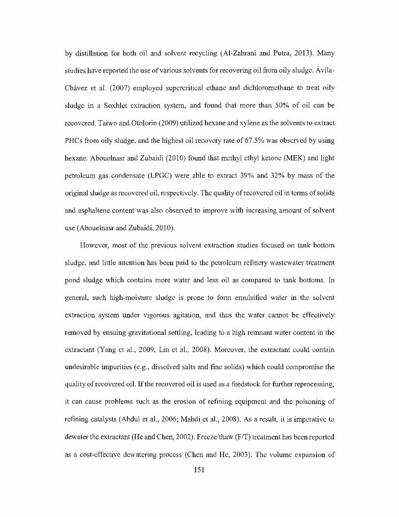
by distillation for both oil and solvent recycling (Al-Zahrani and Putra, 2013). Many
studies have reported the use of various solvents for recovering oil from oily sludge. Avila-
Chavez et al. (2007) employed supercritical ethane and dichloromethane to treat oily
sludge in a Soxhlet extraction system, and found that more than 50% of oil can be
recovered. Taiwo and Otolorin (2009) utilized hexane and xylene as the solvents to extract
PH Cs from oily sludge, and the highest oil recovery rate of 67.5% was observed by using
hexane. Abouelnasr and Zubaidi (2010) found that methyl ethyl ketone (MEK) and light
petroleum gas condensate (LPGC) were able to extract 39% and 32% by mass of the
original sludge as recovered oil, respectively. The quality of recovered oil in terms of solids
and asphaltene content was also observed to improve with increasing amount of solvent
use (Abouelnasr and Zubaidi, 2010).
However, most of the previous solvent extraction studies focused on tank bottom
sludge, and little attention has been paid to the petroleum refinery wastewater treatment
pond sludge which contains more water and less oil as compared to tank bottoms. In
general, such high-moisture sludge is prone to form emulsified water in the solvent
extraction system under vigorous agitation, and thus the water cannot be effectively
removed by ensuing gravitational settling, leading to a high remnant water content in the
extractant (Yang et al., 2009; Lin et al., 2008). Moreover, the extractant could contain
undesirable impurities (e.g., dissolved salts and fine solids) which could compromise the
quality ofrecovered oil. If the recovered oil is used as a feedstock for further reprocessing,
it can cause problems such as the erosion of refining equipment and the poisoning of
refining catalysts (Abdul et al., 2006; Mahdi et al., 2008). As a result, it is imperative to
dewater the extractant (He and Chen, 2002). Freeze/thaw (FIT) treatment has been reported
as a cost-effective dewatering process (Chen and He, 2003). The volume expansion of
151
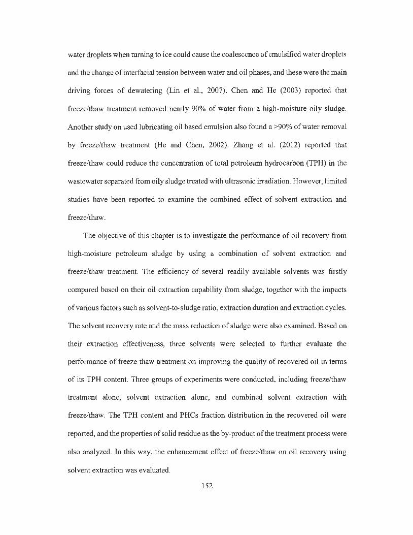
water droplets when turning to ice could cause the coalescence of emulsified water droplets
and the change of interfacial tension between water and oil phases, and these were the main
driving forces of dewatering (Lin et al., 2007). Chen and He (2003) reported that
freeze/thaw treatment removed nearly 90% of water from a high-moisture oily sludge.
Another study on used lubricating oil based emulsion also found a >90% of water removal
by freeze/thaw treatment (He and Chen, 2002). Zhang et al. (2012) reported that
freeze/thaw could reduce the concentration of total petroleum hydrocarbon (TPH) in the
wastewater separated from oily sludge treated with ultrasonic irradiation. However, limited
studies have been reported to examine the combined effect of solvent extraction and
freeze/thaw.
The objective of this chapter is to investigate the performance of oil recovery from
high-moisture petroleum sludge by using a combination of solvent extraction and
freeze/thaw treatment. The efficiency of several readily available solvents was firstly
compared based on their oil extraction capability from sludge, together with the impacts
of various factors such as solvent-to-sludge ratio, extraction duration and extraction cycles.
The solvent recovery rate and the mass reduction of sludge were also examined. Based on
their extraction effectiveness, three solvents were selected to further evaluate the
performance of freeze thaw treatment on improving the quality of recovered oil in terms
of its TPH content. Three groups of experiments were conducted, including freeze/thaw
treatment alone, solvent extraction alone, and combined solvent extraction with
freeze/thaw. The TPH content and PHCs fraction distribution in the recovered oil were
reported, and the properties of solid residue as the by-product of the treatment process were
also analyzed. In this way, the enhancement effect of freeze/thaw on oil recovery using
solvent extraction was evaluated.
152

5 .2 Experimental materials and methods
5.2.1 Materials
The dredged sludge from a petroleum refinery wastewater treatment pond in western
Canada was used as the study sample. A simple random sampling method as recommended
in US EPA SW-846 guideline was used for collecting sludge, while its TPH was
determined as the target contaminant that is of concern in statistical analysis (EPA, 1994).
Figure 5.1 shows the appearance of dredged oily sludge. Compared to tank bottom oily
sludge, dredged wastewater pond sludge was more watery and less sticky. The sample was
stored in a sealed glass jar at 25 °C. It was well stirred manually to obtain an evenly mixing
before use in the experiments. Table 5.1 lists the property of wastewater pond dredged
sludge. The TPH concentration was measured using the US EPA method 80 l 5C (EPA,
2007), and the water content was analyzed by sample drying based on ASTM D2974-00
Method A (ASTM, 2013), while the solid content was calculated according to the
measured TPH and water contents. The metal elements were measured using Inductively
Coupled Plasma (ICP) analysis based on ASTM D5 l 85 (ASTM, 2009). As shown in Table
5.1, the dredged oily sludge contained relatively high amount of water but less amount of
oil, which could pose negative effect such as causing undesirable water-oil emulsions on
oil recovery treatment. In this study, the PHCs in the recovered oil were analyzed and
compared with those of crude oil sample which was obtained from a petroleum refinery in
western Canada. Based on the consideration of toxicity, oil miscibility, economics,
viscosity, and vapor pressure (Hamad et al., 2005; Kheireddine et al., 2013), five organic
solvents were selected for experiments, including cyclohexane (CHX), dichloromethane
153
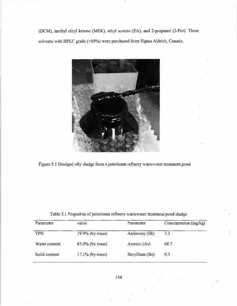
(DCM), methyl ethyl ketone (MEK), ethyl acetate (EA), and 2-propanol (2-Pro ). These
solvents with HPLC grade (>99%) were purchased from Sigma Aldrich, Canada.
Figure 5.1 Dredged oily sludge from a petroleum refinery wastewater treatment pond
Table 5.1 Properties of petroleum refinery wastewater treatment pond sludge
Parameter value Parameter Concentration (mg/kg)
TPH 19.9% (by mass) Antimony (Sb) 3.3
Water content 63.0% (by mass) Arsenic (As) 68.7
Solid content 17.1 % (by mass) Beryllium (Be) 0.3
154
5.2.2 Solvent extraction
5.2.2.1 Extraction procedure
Cadmium (Cd)
Chromium (Cr)
Copper (Cu)
Zinc (Zn)
Lead (Pb)
Nickel (Ni)
Cobalt (Co)
2.0
70.0
159.0
2040.0
64.7
58.5
8.4
Two main factors including solvent-to-sludge (S/S) ratio (v/m) and extraction
duration were investigated in this study to find the desired solvent extraction condition for
oil recovery, and Table 5.2 lists the experimental factor levels, with S/S ratio ranging from
1: 1 to 8: 1, and extraction duration varying from 5 to 90 min. In terms of the extraction
experiment for each solvent, about 5 g of oily sludge was placed in a 50-mL centrifugation
tube, and a given volume of solvent was added according to the specified S/S ratio in Table
5.2. The centrifugation tube was then sealed and placed on a mechanical shaker (Talboy
3500 Orbital Shaker) for shaking extraction at 150 rpm under ambient conditions (Shwab
et al. , 1999). After shaking for a specified extraction duration as shown in Table 5.2, the
mixture was allowed to settle for 24 h at room temperature (25 °C), and three layers were
observed after settling, including an extractant layer (i.e. , oil, solvent and emulsified water
mixture) on the top, an aqueous layer in the middle and the sediment at the bottom. The
middle aqueous (water) layer was removed by a Pasteur pipette, and the top extractant
155

layer was collected to a 100 mL round bottom flask for distillation in a vacuum rotary
evaporator (Yamato RE400) at a temperature of 40 °C. The solvent in this extractant was
evaporated and then condensed as the solvent recovery, while the distillate bottoms in the
flask were considered as the recovered oil (Zubaidy and Abouelnasr, 2010). The remaining
semi-solid residue in the centrifugation tube was air dried in the fume hood for 48 h to
remove any solvent, and then weighed (Mr) and compared with the original sludge mass
(Ms). The residue was also subjected to analyze its properties. The waste reduction rate
was calculated as follows:
M-M Waste reduction rate(%)= - 5 _r X 100
Ms (5.1)
The solvent recovery rate was determined as the ratio of the mass of recovered solvent
to that of original solvent used in the extraction experiment, while the oil recovery rate was
calculated as the ratio of the recovered oil mass to the original sludge mass (Zubaidy and
Abouelnasr, 2010). The quality of the recovered oil was evaluated based on its TPH
content which is determined using GC analysis. All the solvent extraction experiments
were carried out in three replicates. One-way ANOVA was used to determine the
significance (p < 0.05) of statistical difference between treatments.
Table 5.2 Experimental factors and values of solvent extraction
Factors Levels
Solvent type Cyclohexane Dichloromethane Methyl ethyl ketone
Ethyl acetate 2-Propanol
156
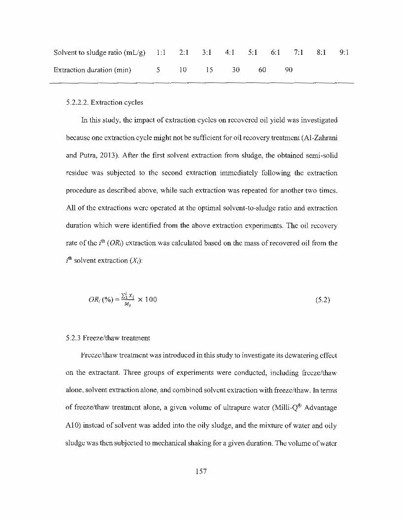
Solvent to sludge ratio (mL/g) 1:1 2:1 3:1 4:1 5:1 6:1 7: 1 8: 1 9:1
Extraction duration (min) 5 10 15 30 60 90
5.2.2.2. Extraction cycles
In this study, the impact of extraction cycles on recovered oil yield was investigated
because one extraction cycle might not be sufficient for oil recovery treatment (Al-Zahrani
and Putra, 2013). After the first solvent extraction from sludge, the obtained semi-solid
residue was subjected to the second extraction immediately following the extraction
procedure as described above, while such extraction was repeated for another two times.
All of the extractions were operated at the optimal solvent-to-sludge ratio and extraction
duration which were identified from the above extraction experiments. The oil recovery
rate of the ith ( ORi) extraction was calculated based on the mass of recovered oil from the
ith solvent extraction (Xi):
ORi (%) = L~Xi x 100 s
(5 .2)
5.2.3 Freeze/thaw treatment
Freeze/thaw treatment was introduced in this study to investigate its dewatering effect
on the extractant. Three groups of experiments were conducted, including freeze/thaw
alone, solvent extraction alone, and combined solvent extraction with freeze/thaw. In terms
of freeze/thaw treatment alone, a given volume of ultrapure water (Milli-Q® Advantage
Al 0) instead of solvent was added into the oily sludge, and the mixture of water and oily
sludge was then subjected to mechanical shaking for a given duration. The volume of water
157
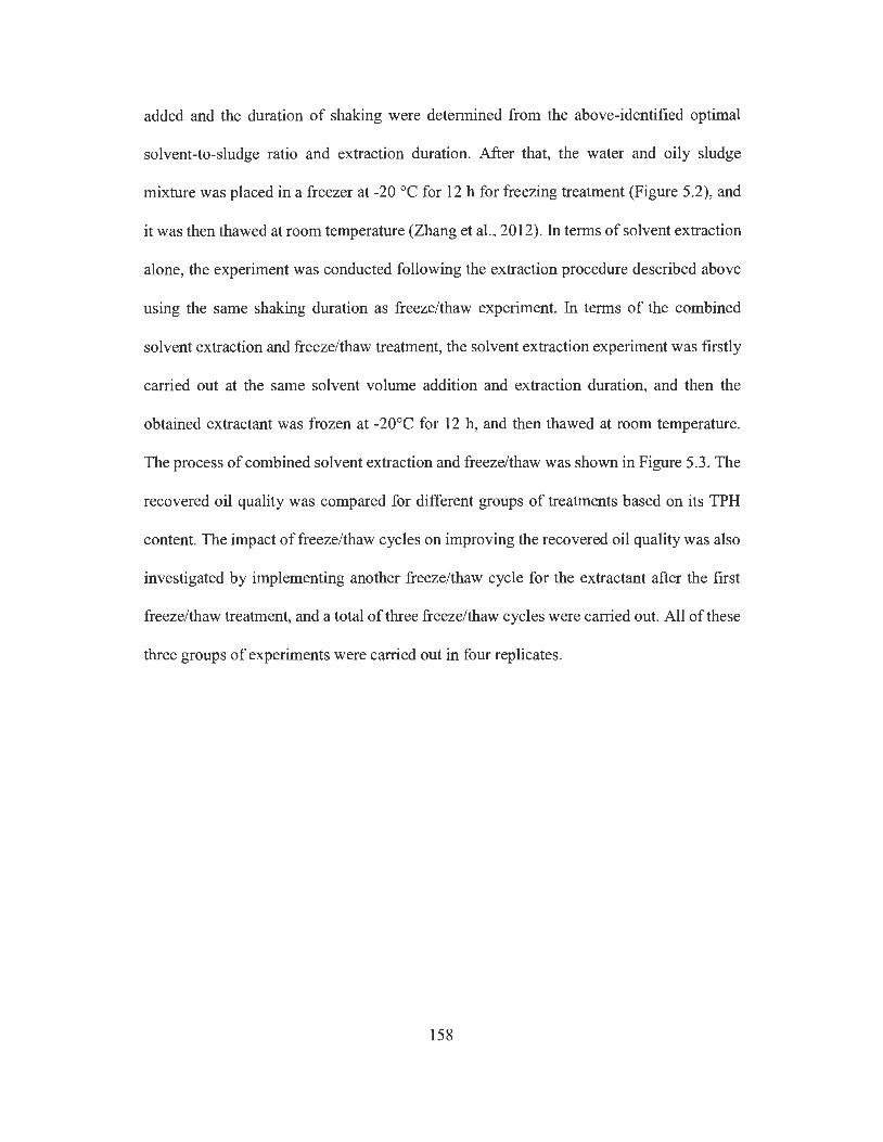
added and the duration of shaking were determined from the above-identified optimal
solvent-to-sludge ratio and extraction duration. After that, the water and oily sludge
mixture was placed in a freezer at -20 °C for 12 h for freezing treatment (Figure 5.2), and
it was then thawed at room temperature (Zhang et al. , 2012). In terms of solvent extraction
alone, the experiment was conducted following the extraction procedure described above
using the same shaking duration as freeze/thaw experiment. In terms of the combined
solvent extraction and freeze/thaw treatment, the solvent extraction experiment was firstly
carried out at the same solvent volume addition and extraction duration, and then the
obtained extractant was frozen at -20°C for 12 h, and then thawed at room temperature.
The process of combined solvent extraction and freeze/thaw was shown in Figure 5 .3. The
recovered oil quality was compared for different groups of treatments based on its TPH
content. The impact of freeze/thaw cycles on improving the recovered oil quality was also
investigated by implementing another freeze/thaw cycle for the extractant after the first
freeze/thaw treatment, and a total of three freeze/thaw cycles were carried out. All of these
three groups of experiments were carried out in four replicates.
158
Solvent
Figure 5.2 Freeze treatment on different extractants at -20 °Cina fridge
Mechanical shaking extraction
... I
'-Water layer Solids
I I
Extractant
Freeze/thaw of extradant
' Emulsified , water
Water layer
Distillation
Figure 5.3 Flow chart of combined solvent extraction and freeze/thaw treatment
5.2.4 Sample analysis
The TPH in recovered oil was measured using GC analysis following the Canadian
Council of Ministers of the Environment (CCME) method (CCME, 2001). The distribution
159
of PH Cs fractions (F2, F3 and F4) was also analyzed, and was compared with that in the
fresh crude oil. The fractions of F2, F3 and F4 were defined as the group of petroleum
hydrocarbons from C10 to C16, C16 to C34, and C34 to Cso, respectively (Zhang et al. , 2012).
The analysis was conducted using a Varian CP-3800 Gas Chromatograph with flame
ionization detector (GC-FID): ZB-capillary column with dimension of 30 m x 0.25 mm x
0.25 µm (Phenomenex Torrance, CA); inject volume of 1 µL; injector and detector (FID)
temperature at 320 °C; carrier gas (helium) at a constant flow rate of 1.5 mL/min during
analysis. The air-dried solid residue after solvent extraction was digested using nitric acid,
and then the ICP method was used to analyze some selected heavy metal species (lead,
chromium, nickel, and zinc) (Al-Futaisi et al., 2007). The total carbon (TC) content in the
residue was analyzed using an ECS 4010 Elemental Combustion System (Costech
Instruments) at 1000 °C with a thermal conductivity detector.
5.3 Results and discussion
5.3.1 Impact of solvent-to-sludge (S/S) ratio
The solvents and solvent-to-sludge ratio had a significant influence on the oil
recovery rate. Figure 5.4a shows the oil recovery rate by different solvents at various
solvent-to-sludge ratio. It can be seen that the oil recovery rate for all solvents generally
increased with the solvent-to-sludge ratio until the equilibrium was reached, with the
lowest oil recovery rate at a ratio of 1: 1. Similar variation trend in oil recovery with
solvent-to-sludge ratio was observed using solvent extraction to treat tank bottom sludge
(Abouelnasr and Zubaidy, 2008; Zubaidy and Abouelnasr, 2010) and used lubricating oil
(Elbashir et al., 2002; Rincon et al. , 2005; Hamad et al., 2005). This is because the increase
in the ratio of solvent to sludge can enhance the mutual solubility of oil in solvent, thereby
160
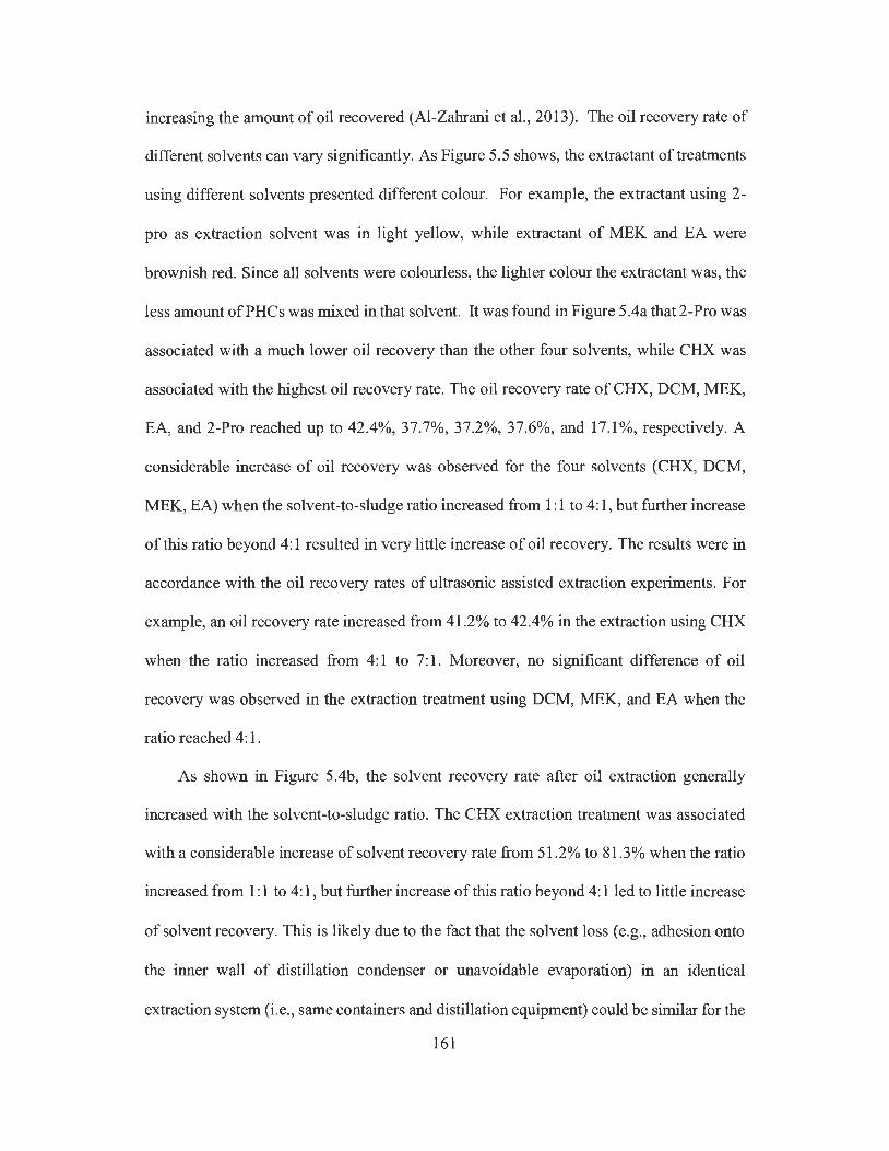
increasing the amount of oil recovered (Al-Zahrani et al., 2013). The oil recovery rate of
different solvents can vary significantly. As Figure 5.5 shows, the extractant of treatments
using different solvents presented different colour. For example, the extractant using 2-
pro as extraction solvent was in light yellow, while extractant of MEK and EA were
brownish red. Since all solvents were colourless, the lighter colour the extractant was, the
less amount of PH Cs was mixed in that solvent. It was found in Figure 5.4a that 2-Pro was
associated with a much lower oil recovery than the other four solvents, while CHX was
associated with the highest oil recovery rate. The oil recovery rate of CHX, DCM, MEK,
EA, and 2-Pro reached up to 42.4%, 37.7%, 37.2%, 37.6%, and 17.1 %, respectively. A
considerable increase of oil recovery was observed for the four solvents (CHX, DCM,
MEK, EA) when the solvent-to-sludge ratio increased from 1: 1 to 4: 1, but further increase
of this ratio beyond 4: 1 resulted in very little increase of oil recovery. The results were in
accordance with the oil recovery rates of ultrasonic assisted extraction experiments. For
example, an oil recovery rate increased from 41.2% to 42.4% in the extraction using CHX
when the ratio increased from 4: 1 to 7: 1. Moreover, no significant difference of oil
recovery was observed in the extraction treatment using DCM, MEK, and EA when the
ratio reached 4: 1.
As shown in Figure 5.4b, the solvent recovery rate after oil extraction generally
increased with the solvent-to-sludge ratio. The CHX extraction treatment was associated
with a considerable increase of solvent recovery rate from 51.2% to 81.3% when the ratio
increased from 1: 1 to 4: 1, but further increase of this ratio beyond 4: 1 led to little increase
of solvent recovery. This is likely due to the fact that the solvent loss ( e.g., adhesion onto
the inner wall of distillation condenser or unavoidable evaporation) in an identical
extraction system (i.e., same containers and distillation equipment) could be similar for the
161
same solvent. As a result, the solvent recovery rate would be calculated as lower when
using a lower volume of solvent for extraction than using a higher volume of solvent under
similar solvent loss condition. It was also found that all the solvents except DCM showed
satisfactory solvent recovery rate, with the highest solvent recovery rate of only 48.5% for
DCM but > 80% for the other four solvents. This might be due to the much higher vapor
pressure of DCM (i.e. , 350 mmHg at 20 °C) than other solvents (i.e. , 73 mmHg for EA, 74
mmHg for MEK, 77.5 mmHg for CHX, and 15 mmHg for 2-Pro at 20 °C). Solvents with
high vapor pressure are prone to cause higher solvent loss because of evaporation during
the extraction process of mixing, settling, and liquid transferring (Kheireddine et al. , 2013).
In this regard, a closed solvent extraction system is desired as it is able to reduce
unnecessary solvent loss (Zubaidy and Abouelnasr, 2010).
162
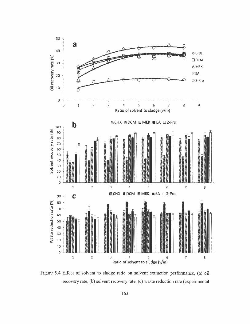
50
40
~ 30 ~
~ ~ 20 0 u ~
6 10
0
* :~ l ~ 70 ~ (:! c: 60 0 ·.g 50 ::::J
] 40 Q) 30 ~
~ 20
10
0
a
___.sJ---0
1 2
1 2
C
1 2
<> CHX
O DCM
6.MEK
X EA
__co~--€Q,---'iQu---,0:,--~09---0 0 2-Pro
3 4 5 6 7 8 9 Ratio of solvent to sludge (v/m)
,J CHX !I DCM Bl MEK • EA D 2-Pro
3 4 5 6 7 8
ri CHX • DCM I:;! MEK • EA D 2-Pro
3 4 5 6 7 8 Ratio of solvent to sludge (v/m)
Figure 5.4 Effect of solvent to sludge ratio on solvent extraction performance, (a) oil
recovery rate, (b) solvent recovery rate, ( c) waste reduction rate ( experimental
163

condition: extraction duration of 120 min at 25 °C; error bar represents
standard deviation, n=3)
Figure 5.5 Extractant of extraction treatments using different solvents
In terms of waste reduction after solvent extraction, it is shown in Figure 5.4c that
more than 50% of original oily sludge mass was reduced in all the treatments. The residue
from solvent extraction treatment consists of mainly solid particles and trace amount of
water and non-extractable PHCs. It is noted that the waste reduction rate for DCM
extraction was the highest (i.e. 80%) among all the treatments, and this rate increased when
the solvent-to-sludge ratio increased from 1: 1 to 4: 1, but no further increase was observed
when the ratio was beyond 4: 1. A possible explanation for this might be that DCM has the
highest density (i.e. 1.326 g/mL) among the five solvents which might hinder the settling
of solid particles in the extractant, while a larger volume of high-density solvent
164

corresponding to a higher solvent-to-sludge ratio could retain more solid particles in the
liquid phase (Hamad et al., 2005; Kheireddine et al., 2013). As a result, the unseparated
solids associated with higher waste reduction rate could increase the content of unwanted
impurities such as fine particles, metals and asphaltene contents in the recovered oil, thus
leading to a lower oil quality. In terms of extraction by the other four solvents, the waste
reduction rate increased from 50.7% to 64.1 % (CHX), 56.3% to 61.5% (MEK), 53 .2% to
66.4% (EA), and 49.3% to 57.2% (2-Pro) as the solvent-to-sludge ratio increased from 1:1
to 4: 1, respectively. Consequently, a solvent-to-sludge ratio of 4: 1 was selected as the
optimal ratio in this study because of the associated high oil and solvent recovery and waste
reduction rates.
5.3.2 Impact of extraction duration
Extraction duration is another important factor that would affect the solvent extraction
performance because long enough duration can allow solvent to dissolve oil and enable
the impurities to aggregate to size big enough to be separated from liquid phase by settling
(Saari et al., 2007; Rincon et al., 2005). As shown in Figure 5.6a, the variation of oil
recovery rate with extraction duration depends on the solvent selected. The highest and
lowest oil recovery was observed for CHX and 2-Pro extraction, respectively, while 2-Pro
extraction achieved a much lower oil recovery than the other four solvents for all of the
extraction durations, indicating that 2-Pro was not an effective solvent for petroleum
refinery wastewater sludge extraction. Abouelnasr and Zubaidy (2008) reported similar
results that iso-propanol and iso-butanol can only recover 8% of oil from the tank bottom
sludge, suggesting that alcohol is not a suitable solvent for refinery oily sludge recycling.
Figure 5.6a also indicates that for extraction using CHX, MEK, and 2-Pro, the oil recovery
165
rate increased with the extraction duration until reaching equilibrium at the extraction
duration of 30 min. For example, the oil recovery rate of CHX extraction increased from
36.1 % to 41.5% as the extraction duration extended from 5 min to 30 min. However,
extraction duration showed little effect on oil recovery when using DCM and EA for
extraction, with a slight increase of oil recovery rate from 34.6% at 5 min to 36.6% at 30
min when using EA extraction. In terms of solvent recovery, as shown in Figure 5.6b, its
variation with extraction duration was not obvious for all the solvents although DCM
extraction was associated with the lowest solvent recovery rate (i.e. < 50%) as compared
with the other four solvents (i.e. > 80% of solvent recovery). Similarly, the extraction
duration illustrated little effect on the variation of waste reduction rate when using CHX,
MEK, EA, and 2-Pro extraction (Figure 5.6c). For DCM extraction, the waste reduction
increased from 62.6% to 77.7% as the extraction duration increased from 5 min to 30 min
when the equilibrium was reached. By considering the overall effect on oil recovery, the
mechanical shaking extraction 30 min was selected as the optimum in this study. This
duration would be long enough to achieve satisfactory miscibility between solvent and oil
in the petroleum sludge.
166

50 a
40 -::)-2-Pro e ->-CHX Q) 30 ..... ro -o-MEK .... > .... Q) 20 ~ EA > 0 Q 0 u -0 Q)
~ - CJ- DCM ....
·- 10 0
0 20 40 60 80 100
Extraction duration (min)
100
* b IIJ CHX • DCM ISi MEK • EA D 2-Pro
cf rf m rn ~ m Q) 80 ..... ro .... c:-Q) 60 > 0 u Q) .... ..... 40 C: Q) 2: 0 20 11'1
0 5 10 15 30 60 90
Extraction duration (min)
100 !/?ii CHX • DCM m MEK • EA D 2-Pro C
l <1J ..... 80 ro .... C: .Q 60 ..... u ;:J
a r:E cE a: dl :E
-u Q) .... 40 Q) ..... V'I ro s 20
0 5 10 15 30 60 90
Extraction duration (min)
167
Figure 5.6 Effect of extraction duration on solvent extraction performance, (a) oil recovery
rate, (b) solvent recovery rate, ( c) waste reduction rate ( experimental condition:
solvent-to-sludge ratio (v/m) of 4: 1 at 25 °C; error bar represents standard
deviation, n=3)
5.3.3 Extraction cycle
From the results presented above, three solvents including CHX, MEK, and EA were
selected for further investigation under the solvent-to-sludge ratio of 4: 1 and extraction
duration of 30 min. DCM and 2-Pro were excluded because of their low solvent recovery,
inadequate settling of solids, and poor oil extraction performance. As seen in Figure 5.7,
the oil recovery rate generally increased with the solvent extraction cycles. After one
solvent extraction cycle, CHX achieved a higher oil recovery (i.e., 41.0%) as compared to
that ofMEK (i.e. 35.4%) and EA (i.e. 35.8%). After the second extraction, the oil recovery
rate increased to 56.0% (CHX), 40.4% (MEK), and 38.3% (EA), respectively. Some heavy
oil components might still be attached to the solids and settled after the first extraction,
and the increase of extraction cycle could help further extract such components in the
solids although the oil recovery increment was not significant for MEK (i.e. 5.0%) and EA
(i.e. 2.5%). However, the increase of solvent extraction cycle number to three only resulted
in very slight oil recovery increment for all the three solvents (Figure 5.6), indicating that
only one or two extractions cycles could be enough for the study sludge.
168

70
es ~ 60
~ 'ii
Q) 50 +"' ro
~ ~ ... > 40 ... Q) ~ > 0 30 u Q) ... 0 20
<> CHX 6.MEK X EA 10
0 1 2 3 4
Cycles of extraction
Figure 5. 7 Effect of solvent extraction cycles on oil recovery rate
5.3.4 Freeze/thaw enhancement
The solvent-to-sludge or water-to-sludge ratio of 4: 1 and mechanical shaking duration
of 30 min were used to conduct the three groups of experiments to examine the effect of
freeze/thaw treatment. In this study, no noticeable oil separation was observed when using
freeze/thaw (FIT) treatment alone (experimental data not shown), indicating that FIT
treatment alone was not effective for oil recovery from refinery wastewater pond sludge.
The possible explanation is that in the original sludge, PH Cs were strongly attached to the
solids, which cannot be effectively separated by freeze/thaw alone. Figure 5.8 presents the
effect of solvent extraction alone and the combined solvent extraction with FIT treatment
on the oil recovery performance. As shown in Figure 5.8a, after solvent extraction
treatment, the extractant contained a large amount of emulsified water, which cannot be
effectively separated via gravitational settling. During freezing, these emulsified water
droplets formed ice lattice in the extractant (shown as the shadow area in the extractant),
leaving the mixture of solvent and oil unfrozen in the centrifugation tube. After thawing at
169

room temperature, it was observed that the height of separated water layer in the tube with
FIT treatment was generally higher than that without FIT treatment (Figure 5.8b-d), which
indicates an effective dewatering effect of FIT was taken place on extractant. Moreover,
the discrepancy in the height of the separated water between FIT treatment and non FIT
treatment was more obvious for MEK and EA as compared with CHX extraction,
suggesting that the FIT enhancement was more effective in dewatering of extractant from
treatments using EA and MEK. As a result, more emulsified water can be removed from
the extractant by using FIT for these two solvents, leading to reduced water content in the
recovered oil.
170

Figure 5.8 Effect of freeze/thaw enhanced solvent extraction and the comparison of
separated water level from the extractant with freeze/thaw treatment (left
yellow bar) and without freeze/thaw treatment (right red bar), (a) ice lattice
171

formation in the extractant from MEK extraction, (b) CHX extraction, ( c)
MEK extraction, and ( d) EA extraction
As shown in Figure 5.9a, the TPH contents in the recovered oil were generally lower
for solvent extraction alone in terms of all the three solvents. However, the combined
solvent extraction with freeze/thaw treatment can significantly (p < 0.05) increase the TPH
content in the recovered oil for both MEK and EA extractions. For example, with FIT
treatment, the TPH content in the recovered oil increased from 41.8% to 62.6% when using
MEK extraction and from 41.0% to 58.8% when using EA extraction. The improvement
of FIT treatment on TPH content in the recovered oil by CHX extraction was not significant
(p > 0.05). The mechanism for enhanced dewatering by freeze/thaw is the coalescence of
the adjacent water droplets in the W/0 emulsion (Ghosh and Coupland, 2008). During
freezing, the dimension of emulsified water droplets grows as the temperature decreases
and the interfacial film between water and oil becomes thinner. When the temperature
drops below the melting point of water, the ice crystal is formed and it could then break
the interfacial film to form bridge between the adjacent water droplets. During the thawing
process, these connected adjacent water droplets allows coalescence to happen, and thus
an even larger droplet can be formed which can then be readily separated by gravitational
settling (Yang et al., 2009; Lin et al., 2008; Lin et al., 2007). The insignificant dewatering
effect of freeze/thaw on the extractant from CHX extraction might be due to the higher
melting point of this solvent (i.e. 6.5°C) than that of water. The CHX could be frozen
before the emulsified water in the extractant, and this frozen continuous solvent phase
might act as a barrier that hinders the connection of ice crystals from frozen water droplets,
and thus leading to difficulty in the coalescence of water droplets. Lin et al. (2008) also
172
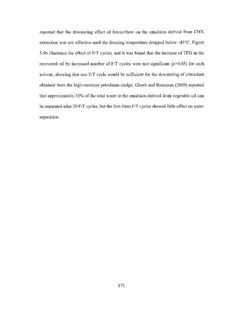
reported that the dewatering effect of freeze/thaw on the emulsion derived from CHX
extraction was not effective until the freezing temperature dropped below -45°C. Figure
5.9b illustrates the effect of FIT cycles, and it was found that the increase of TPH in the
recovered oil by increased number of FIT cycles were not significant (p>0.05) for each
solvent, showing that one FIT cycle would be sufficient for the dewatering of extractant
obtained from the high-moisture petroleum sludge. Ghosh and Rousseau (2009) reported
that approximately 35% of the total water in the emulsion derived from vegetable oil can
be separated after 20 FIT cycles, but the first three FIT cycles showed little effect on water
separation.
173
70 a 60
BEi Without F/T '*- 5o • With F/T ..... @ 40 ..... C:
8 30 :::c ~ 20
10
0
80
70
'eR 60
~ 50 QJ
~ 40 0 u
:::c 30 0.. 1- 20
CHX
b
CHX
MEK EA
@ Cycle 1 • Cycle 2 1§.'1 Cycle 3
MEK
Solvents EA
Figure 5.9 Effect of freeze/thaw (FIT) treatment on (a) TPH content in recovered oil by
solvent extraction and (b) TPH content in recovered oil as a function of FIT
cycle
5.3.5 Characteristics ofrecovered oil and solid residue
As shown in Figure 5.10, the F2, F3, and F4 fractions accounted for 26.5%, 69.1 %,
and 4.3% of TPH in the recovered oil by CHX extraction with freeze/thaw. On the other
hand, the F2 and F3 fractions in the oil recovered by the combination of MEK or EA
extraction with freeze/thaw treatment were slightly higher, while the F4 fraction was lower
than that from CHX extraction. Most volatile PHCs such as the Fl fraction (i.e. C6-C10)
174

can be evaporated during oily sludge storage, leaving the relatively heavy fractions such
as F2 to F4 in oily sludge available for recovery (Heidarzadeh et al. , 2010). Consequently,
the recovered oil normally contains a relatively large amount ofF2 and F3 fractions which
account for >80% ofTPH in the recovered oil (Zhang et al., 2012). In comparison to crude
oil, the recovered oil from the study sludge contained more F3 fraction but less F2 fraction
(Figure 5.10), and it could be suitable for use as a feedstock for heavy fuel oil production
(Smith et al., 2003).
80
70
60 ~ Q) 50 tl.D
~ 40 s:: Q) u <ii 30 Q.
20
10
0 F2 F3
PHCs fractions
~ CHX
• MEK
~ EA
D Fresh crude
F4
Figure 5.10 Distribution of PH Cs fractions in fresh crude oil and the recovered oil by using
the combination of solvent extraction with freeze/thaw
Solid residue is the by-product of oil recovery treatment and it requires proper
treatment before disposal of to avoid causing any secondary pollution. As Figure 5.11
shows, the solid residue were mainly consisted of two layers: a thin non-extractable PHCs
(i.e., asphaltenes and resins) layer on the top and soil particle layer at the bottom. As shown
in Table 5.3, after treatment using the combination of solvent extraction with freeze/thaw,
the TPH content in the solid residue was significantly lower than that in the original oily
175

sludge, with more than half of the TPH in oily sludge being recovered by solvent extraction.
The total carbon (TC) content also declined, while the TPH and TC contents in the solid
residue decreased with the increase of solvent extraction cycles. It was observed that
residues after CHX extraction contained the highest TPH and TC contents as compared
with those after MEK and EA extractions. Although solvent extraction showed obvious
effect on oil recovery from the oily sludge, the TPH content in the solid residue was still
much higher than the clean-up level (i.e. < 10,000 mg/kg of TPH in the soil at industrial
area) recommended by Canadian Council of Ministers of the Environment (CCME, 2008),
indicating that the residue still requires proper management prior to final disposal. The
variation of heavy metal concentrations in the solid residue showed an opposite direction,
while such concentration generally increased with the solvent extraction cycles. The results
revealed that solvent extraction with freeze/thaw treatment had little removal effect on
heavy metals in oily sludge, and most heavy metals were remained and accumulated in the
solid residues. The heavy metal concentration in the solid residue generally increased due
to the mass reduction of sludge after extraction treatment. Although these concentrations
( except Ni) were lower than their regulatory limits in soils set by US EPA (i.e. 7500 mg/kg
for Zn, 420 mg/kg for Pb, 75 mg/kg for Ni, and 3000 mg/kg for Cr) (EPA, 1993), the
increased heavy metal contents in the solid residues from oil recovery treatment by solvent
extraction with freeze/thaw could still be a potential environmental problem which requires
proper management.
176
Figure 5.11 Solid residues from refinery wastewater pond sludge after combined solvent
extraction and freeze/thaw treatment
177
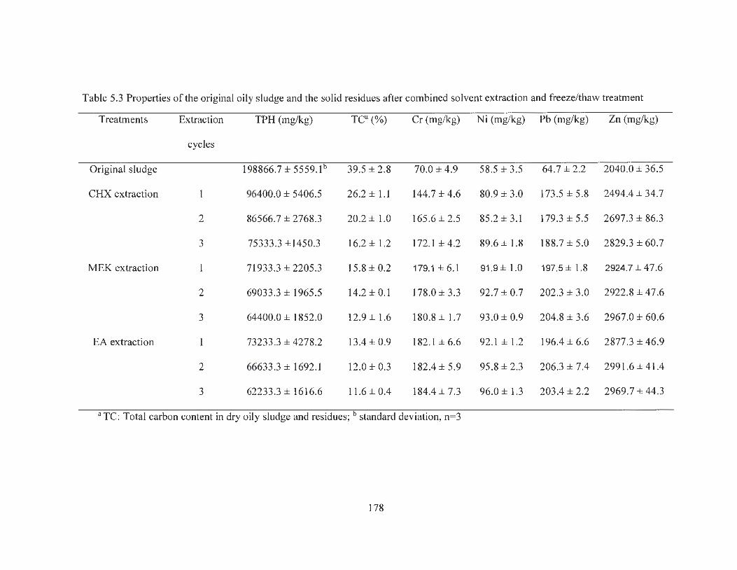
Table 5.3 Properties of the original oily sludge and the solid residues after combined solvent extraction and freeze/thaw treatment
Treatments Extraction TPH (mg/kg) Tea (%) Cr (mg/kg) Ni (mg/kg) Pb (mg/kg) Zn (mg/kg)
cycles
Original sludge 198866.7± 5559.lb 39.5 ± 2.8 70.0 ± 4.9 58.5 ± 3.5 64.7 ± 2.2 2040.0 ± 36.5
CHX extraction I 96400.0 ± 5406.5 26.2± 1.1 144.7 ± 4.6 80.9 ± 3.0 173.5 ± 5.8 2494.4 ± 34.7
2 86566.7 ± 2768.3 20.2 ± 1.0 165.6 ± 2.5 85 .2±3.1 179.3 ± 5.5 2697.3 ± 86.3
3 75333 .3 ±1450.3 16.2 ± 1.2 172.1 ± 4.2 89.6 ± 1.8 188.7 ± 5.0 2829.3 ± 60.7
MEK extraction 1 71933.3 ± 2205.3 15.8 ± 0.2 179.1±6.1 91.9 ± 1.0 197.5± 1.8 2924.7 ± 47.6
2 69033.3 ± 1965.5 14.2 ± 0.1 178.0 ± 3.3 92.7 ± 0.7 202.3 ± 3.0 2922.8 ± 47.6
3 64400.0 ± 1852.0 12.9 ± 1.6 180.8± 1.7 93.0 ± 0.9 204.8 ± 3.6 2967.0 ± 60.6
EA extraction 1 73233.3 ± 4278.2 13.4 ± 0.9 182.1 ± 6.6 92.1 ± 1.2 196.4 ± 6.6 2877.3 ± 46.9
2 66633.3 ± 1692.1 12.0 ± 0.3 182.4 ± 5.9 95.8 ± 2.3 206.3 ± 7.4 2991.6 ± 41.4
3 62233 .3 ± 1616.6 11.6 ± 0.4 184.4 ± 7.3 96.0 ± 1.3 203.4 ± 2.2 2969.7 ± 44.3
a TC: Total carbon content in dry oily sludge and residues ; b standard deviation, n=3
178
5.4 Conclusions
Oil recovery from the high-moisture oily sludge was investigated using solvent
extraction and freeze/thaw treatment. Three solvents including CHX, MEK and EA were
identified as ideal candidates based on their oil recovery and solvent recovery
performances. They can achieve about 40% of oil recovery after 30 min of shaking
extraction at a solvent-to-sludge ratio of 4: 1, while more than 80% of solvent can be
recycled. However, the TPH content in the recovered oil was relatively low (i.e. about 30%
by CHX and 40% by MEK or EA extraction) because of the presence of emulsified water.
It was found that freeze/thaw treatment can significantly increase the TPH content in the
recovered oil from MEK or EA extraction (i.e. from 40% to 60%) by dewatering of the
extractant, but little effect was observed for the combination of CHX extraction with
freeze/thaw. The recovered oil mainly consisted ofF2 and F3 fractions of PH Cs. The TPH
and total carbon contents in the solid residue after solvent extraction with freeze/thaw
treatment can be significantly reduced, but the heavy metal concentrations increased. In
summary, the combination of solvent extraction with freeze/thaw process could represent
an effective and feasible approach for the management of the hazardous high-moisture oily
waste in terms of its satisfactory oil recovery rate and the increased TPH content in the
recovered oil.
179
Chapter 6 Treatment of refinery oily sludge through co-pyrolysis with wood waste
6.1 Introduction
The petroleum industry generates a considerable amount of oily sludge during various
processes such as crude oil exploration, transportation, storage, and refining. An annual
production and total accumulation of oily sludge in the world was estimated to be over 60
million and 1 billion tons, respectively (da Silva et al. , 2012; Hu et al. , 2013). This type of
sludge is a complex and stable emulsion of various petroleum hydrocarbons (PH Cs), water,
solid particles, and metals (Hu et al., 2015). It has been classified as a hazardous waste in
many countries since it may contain various carcinogenic polycyclic aromatic
hydrocarbons (P AHs) such as benzene, phenol, anthracene, and pyrene (Roldan et al. , 2012;
Naik et al. , 2011). Due to its hazardous nature and increasing production quantity, the
effective treatment of oily sludge has become a worldwide pressing need.
Traditional methods for oily sludge treatment such as landfilling have been
challenged by increasingly stringent regulations because of their low efficiency, long
treatment time, and possible secondary pollution (Chirwa et al., 2013). In recent years, the
recycling of energy from such oil-rich waste while minimizing its adverse environmental
impact has received increasing interests, and a variety of physical, chemical, and biological
methods as well as their combinations have been developed (Hu et al. , 2013). Among these
methods, pyrolysis represents an effective thermo-chemical conversion process during
which oily waste is heated in a closed oxygen-free reactor system at moderate operating
temperature (i.e. , usually 200 to 500 °C) (Isahak et al. , 2012; Bridgwater, 2012). This
180
process can convert organic matters into combustible gases, pyrolysis oil, and char. The
combustible gas and pyrolysis oil can be used for energy resource and the char after proper
modification can be used as an adsorbent for pollution control (Bridgwater, 2012; Zhang
et al. , 2013). A few studies reported that pyrolysis can be effective for oily sludge treatment.
For example, Karayidirim et al. (2006) observed that 30.0% of pyrolysis oil and 15.0% of
gas (i.e. , hydrogen, methane, and carbon monoxide) can be produced from the pyrolysis
of oily sludge collected from the primary decanting step following API separation in the
wastewater treatment plant of a refinery. Liu et al. (2009) found that around 80.0% of total
organic carbon can be converted into hydrocarbons gas through pyrolysis when heating
the tank bottom oily sludge sample to a temperature range of 473-723 K. Molt6 et al. (2013)
examined the pyrolysis of two different sludge wastes (i.e. , petrochemical sludge and
biological sludge) and found that the gaseous products can be significantly affected by the
heating rate, oxygen content, contact time, and the nature of sludge. Conesa et al. (2014)
investigated the pyrolysis of petrochemical sludge and observed an increased yield of
liquid oil (i.e. , from 30 to 50%) due to increasing treatment temperature (i .e ., from 350 to
530 °C).
In addition to the application to oily sludge waste treatment, many pyrolysis studies
have focused on pyrolysis oil production from biomasses (i .e. , mainly lignocellulosic
plants) because they are considered as abundant and promising renewable energy sources
(Pootakham and Kumar, 201 O; Butler et al. , 2011 ). Biomass derived pyrolysis oil ( e.g. bio-
oils) possesses several environmental advantages over fossil fuels such as less undesirable
gaseous emission of CO2, SOx, and NOx (Isahak et al., 2012). A variety of biomasses such
as wood and agricultural residues have been used as feedstock for producing bio-oils via
pyrolysis (Ki et al., 2013; Asadullah et al. , 2013; Abnisa and Daud, 2014). In general, the
181
bio-oil yield and properties can be significantly affected by pyrolysis temperature and the
nature offeedstock (Chen et al., 2013). Although showing a great potential as an alternative
energy source, the utilization of bio-oil has been limited due to some drawbacks such as
high oxygen and water content, low heating value, and instability (Isahak et al., 2012). It
is thus of importance to find effective solution for improving the biomass pyrolysis. The
co-pyrolysis of biomass with other organic wastes seems to be a simple and effective way
for such improvement not only in pyrolysis oil quality but also in yield (Abnisa and Daud,
2014). Biomass and organic wastes usually have different chemical and physical properties
such as moisture, volatile matter, ash content, calorific value, porosity, and
oxygen/hydrogen/carbon (0/H/C) molar ratio. The differing properties can change the
reactivity and thermal characteristics of samples and products, and the formation of
synergistic interaction during co-pyrolysis could then result in an improved pyrolysis
product (Kar, 2011 ).
Many efforts have been made to investigate the co-pyrolysis of biomass with other
wastes, such as waste tires (Martinez et al., 2013), plastic wastes (Pinto et al., 2013), and
municipal sewage sludge (Samanya et al. , 2012). For example, Cao et al. (2009) found that
the liquid oil product from the co-pyrolysis of sawdust with waste tires had a higher heating
value (HHV) of 42.44 MJ/kg, which is much higher than that (28 .51 MJ/kg) from the
pyrolysis of sawdust alone. Brebu et al. (2010) examined the co-pyrolysis of pine cone
with synthetic polymers and found that the oil yield increased from 47.5 to 69.7 wt.%.
Onal et al. (2014) investigated oil production by co-pyrolysis of almond shell with high
density polyethylene, and observed that the produced oil via co-pyrolysis had an improved
heating value (i.e., by 38%) but a much decreased oxygen content (i.e., by 86%) than those
from biomass pyrolysis alone. Zuo et al. (2014) also observed that the HHV of oil product
182

can be improved by the co-pyrolysis of sewage sludge with poplar sawdust as compared
to pyrolysis of sewage sludge alone. However, so far there has been limited research
investigating the co-pyrolysis of biomass with refinery oily sludge. As a result, the present
study aims to examine the treatment of refinery oily sludge waste using co-pyrolysis with
a wood waste (saw dust). The synergistic effect of oily sludge addition to sawdust on
pyrolysis oil and char products was investigated. The co-pyrolysis was carried out in a
fixed-bed reactor under different pyrolysis conditions. A number of experimental factors
were examined, including sawdust percentage in the feedstock mixture, temperature, and
heating rate. The main and interaction effects of these factors on the yield of pyrolysis oil
and the solid char were evaluated through a response surface methodology (RSM). The
quality of pyrolysis product was also analyzed. The results would provide valuable
information for developing an effective oily sludge waste management approach in terms
of both resource recycling and minimizing adverse environmental effects.
6.2 Experiment
6.2.1 Materials
Wood waste (Douglas fir sawdust) was collected from a wood industry, and oily
sludge was collected from tank bottom periodical cleaning at an oil refinery in western
Canada (Figure 6.1 ). The sludge and sawdust samples were oven dried at 80 and 105°C
for 8 h to remove moisture, respectively (Liu et al., 2013; Tian et al., 2014). The sawdust
was ground in a high-speed rotary cutting mill and then screened into particles of about 1
mm in diameter. Table 6.1 lists the sample properties and their test methods.
183
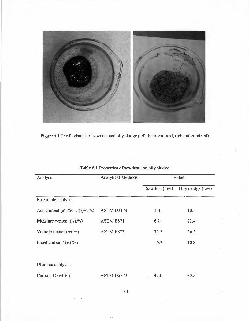
Figure 6.1 The feedstock of sawdust and oily sludge (left: before mixed; right: after mixed)
Table 6.1 Properties of sawdust and oily sludge
Analysis Analytical Methods Value
Sawdust (raw) Oily sludge (raw)
Proximate analysis:
Ash content (at 750°C) (wt.%) ASTMD3174 1.0 10.3
Moisture content (wt.%) ASTME871 6.2 22.4
Volatile matter (wt.%) ASTME872 76.5 56.5
Fixed carbon a (wt.%) 16.3 10.8
Ultimate analysis:
Carbon, C (wt.%) ASTMD5373 47.0 60.5
184
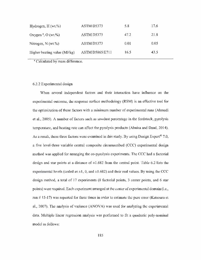
Hydrogen, H (wt.%) ASTMD5373 5.8 17.6
Oxygen 3, 0 (wt.%) ASTMD5373 47.2 21.8
Nitrogen, N (wt.%) ASTMD5373 0.01 0.05
Higher heating value (MJ/kg) ASTM D5865/E711 16.5 43.5
a Calculated by mass difference.
6.2.2 Experimental design
When several independent factors and their interaction have influence on the
experimental outcome, the response surface methodology (RSM) is an effective tool for
the optimization of these factors with a minimum number of experimental runs (Ahmadi
et al., 2005). A number of factors such as sawdust percentage in the feedstock, pyrolysis
temperature, and heating rate can affect the pyrolysis products (Abnisa and Daud, 2014).
As a result, these three factors were examined in this study. By using Design Expert® 7.0,
a five level-three variable central composite circumscribed (CCC) experimental design
method was applied for arranging the co-pyrolysis experiments. The CCC had a factorial
design and star points at a distance of ±1.682 from the central point. Table 6.2 lists the
experimental levels (coded as ±1, 0, and ±1.682) and their real values. By using the CCC
design method, a total of 17 experiments (8 factorial points, 3 center points, and 6 star
points) were required. Each experiment arranged at the center of experimental domain (i.e.,
run# 15-17) was repeated for three times in order to estimate the pure error (Katsoura et
al., 2007). The analysis of variance (ANOV A) was used for analyzing the experimental
data. Multiple linear regression analysis was performed to fit a quadratic poly-nominal
model as follows:
185

3 3 2 3
Y = Po + L Pixi + L Puxf + LL PijxixJ Eq. (6.1) i=l i=l i=l J>i
Where y is the response variable (i.e. pyrolysis oil or char yield); x; or XJ is the
independent variable (i.e. the three experimental factors); Po, p;, Pu, and PiJ are the intercept,
linear, quadratic, and interaction coefficients of the model, respectively. RSM was used to
illustrate the main and interaction effects of experimental factors . The optimal co-pyrolysis
condition for maximum oil yield was identified using the numerical optimization function
of Design Expert® 7.0 software (Katsoura et al., 2007).
6.2.3 Pyrolysis procedure
Each pyrolysis experiment was carried out in a fixed-bed tube furnace reactor (quartz
tube length: 600 mm, 0 : 50 mm; MTI Corp.® GSL-1 IOOX) under atmospheric pressure.
(Figure 6.2). The schematic experimental set-up was shown in Figure 6.3. About 20 g of
feedstock (i.e. , sawdust and oily sludge mixture) was put into the sample ark which was
placed in the center section of the tube reactor. The sweeping nitrogen gas was passed
through the tube reactor at a constant flow rate of 100 mL/min. Samples were heated to
the set temperature at a given heating rate as listed in Table 6.2. The hot vapors from
pyrolysis were condensed in three ice-water cooling traps (Chen et al. , 2013). After
pyrolysis, the liquid oil product was collected from the cooling traps and weighed. The
pyrolysis oil yield was then calculated by dividing the mass of collected oil to the mass of
feedstock. Char yield was measured by dividing the mass of char remaining after pyrolysis
to the mass of original feedstock, while the gas yield was determined by overall mass
186
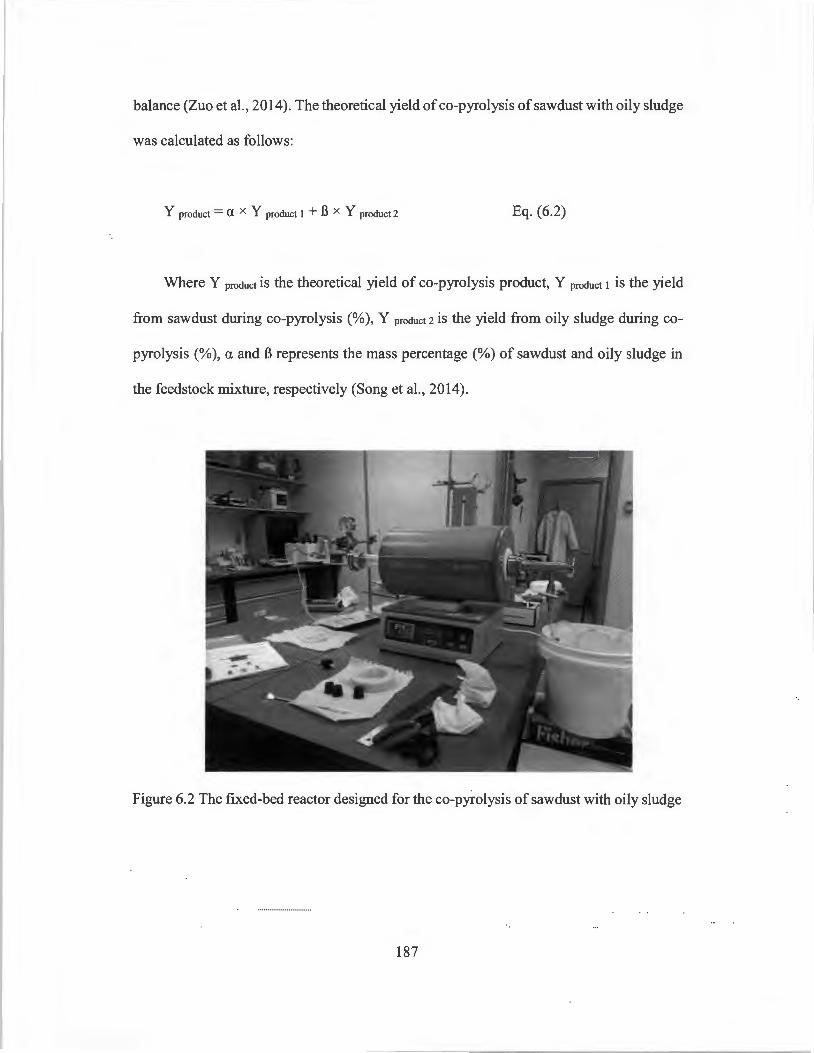
balance (Zuo et al., 2014). The theoretical yield of co-pyrolysis of sawdust with oily sludge
was calculated as follows:
Y product = a X Y product I + B X Y product 2 Eq. (6.2)
Where Y product is the theoretical yield of co-pyrolysis product, Y product I is the yield
from sawdust during co-pyrolysis (%), Y product 2 is the yield from oily sludge during co-
pyrolysis (%), a and B represents the mass percentage (%) of sawdust and oily sludge in
the feedstock mixture, respectively (Song et al., 2014).
Figure 6.2 The fixed-bed reactor designed for the co-pyrolysis of sawdust with oily sludge
187

Thermal couple
Tube furnace reactor
Gases to fume hood
Flow meter
0 0 Cooling trap
Temperature control
Figure 6.3 Schematic diagram of fixed-bed pyrolysis reactor
6.2.4 Sample analysis
Some physical properties of pyrolysis oil were determined by using the following
standard test methods: the specific gravity (ASTM D4052), the higher heating value
(ASTM D240), and water content (ASTM E203). The thermo-gravimetric analysis
(TGA) and differential thermal-gravimetric (DTA) analysis were performed using a TA
Instruments® Q500 thermo-gravimetric analyzer to measure the thermal behavior of
sawdust and oily sludge from room temperature to 1000°C. The analysis was carried out
at 10 mg sample, 100 mL/min nitrogen gas flow with 20°C/min heating rate. The
ultimate analyses of feedstock, pyrolysis oil and char were carried out by a Costech®
ECS 4010 elemental analyzer according to ASTM D5291 method.
188
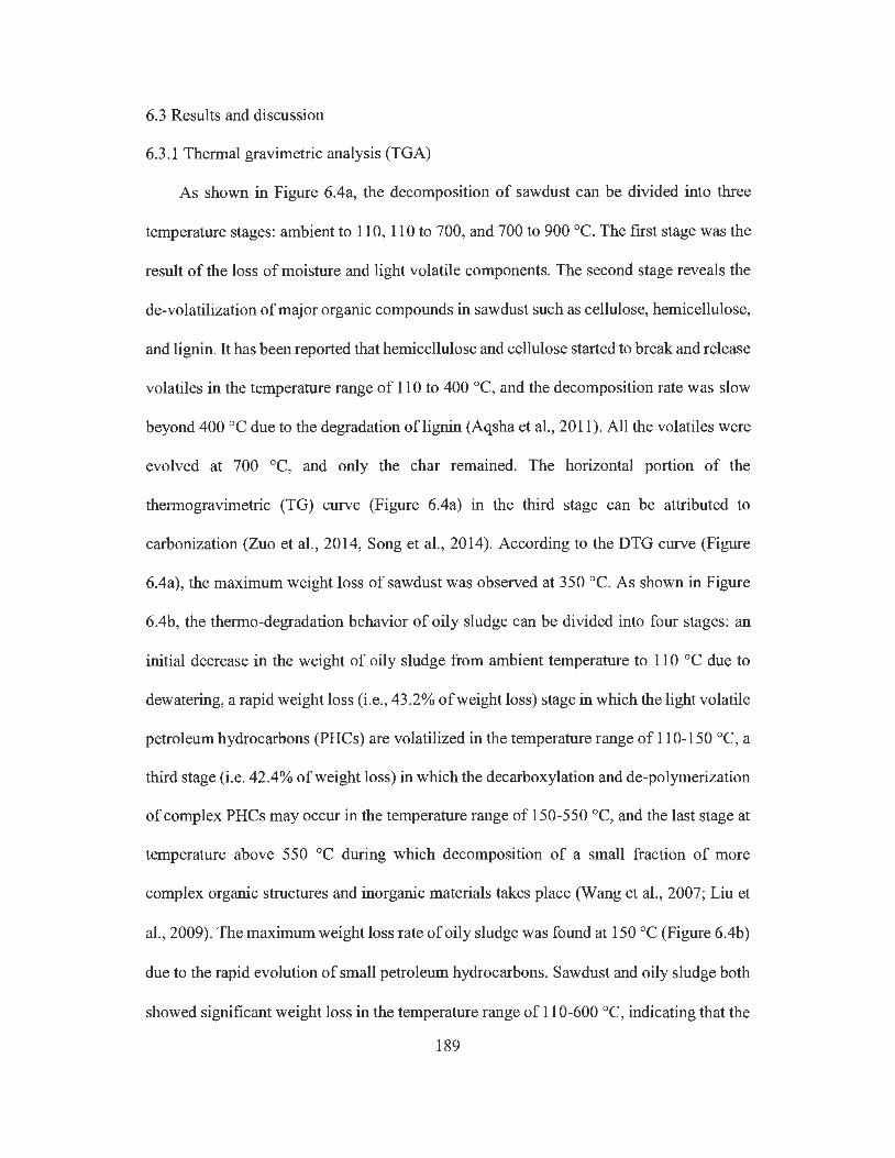
6.3 Results and discussion
6.3.1 Thermal gravimetric analysis (TGA)
As shown in Figure 6.4a, the decomposition of sawdust can be divided into three
temperature stages: ambient to 110, 110 to 700, and 700 to 900 cc. The first stage was the
result of the loss of moisture and light volatile components. The second stage reveals the
de-volatilization of major organic compounds in sawdust such as cellulose, hemicellulose,
and lignin. It has been reported that hernicellulose and cellulose started to break and release
volatiles in the temperature range of 110 to 400 cc, and the decomposition rate was slow
beyond 400 cc due to the degradation oflignin (Aqsha et al. , 2011). All the volatiles were
evolved at 700 cc, and only the char remained. The horizontal portion of the
thermogravimetric (TG) curve (Figure 6.4a) in the third stage can be attributed to
carbonization (Zuo et al. , 2014, Song et al. , 2014). According to the DTG curve (Figure
6.4a), the maximum weight loss of sawdust was observed at 350 cc. As shown in Figure
6.4b, the thermo-degradation behavior of oily sludge can be divided into four stages: an
initial decrease in the weight of oily sludge from ambient temperature to 110 cc due to
dewatering, a rapid weight loss (i.e. , 43 .2% of weight loss) stage in which the light volatile
petroleum hydrocarbons (PHCs) are volatilized in the temperature range of 110-150 cc, a
third stage (i.e. 42.4% of weight loss) in which the decarboxylation and de-polymerization
of complex PH Cs may occur in the temperature range of 150-550 cc, and the last stage at
temperature above 550 cc during which decomposition of a small fraction of more
complex organic structures and inorganic materials takes place (Wang et al., 2007; Liu et
al. , 2009). The maximum weight loss rate of oily sludge was found at 150 cc (Figure 6.4b)
due to the rapid evolution of small petroleum hydrocarbons. Sawdust and oily sludge both
showed significant weight loss in the temperature range of 110-600 cc, indicating that the
189
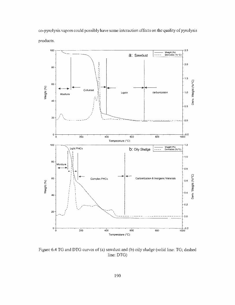
co-pyrolysis vapors could possibly have some interaction effects on the quality of pyrolysis
products.
l .E C,
~
~ 0
.E
.S!'
~
100~--,-------------------------,-----------.2.s
80
60
Cellulose Moisture
40
I r, r, 11 ,, 11 IJ r, 11 , , I 1 :--+.___
I I I I I I I I I I
Lignin
a: Sawdust Weight(%) De,ivative (%/'C)
carbonization
2.0
1.5
1.0
0.5
- --- ---------------- - 0.0
04-------~~-~-~----~-~~-~-~----~-~---+~.5 0 200 400 600 800 1000
Temperature (°Cl 100,--"""",---------------- ---------,---------,- 1,2
Light PHCs ~ ,, 11 11
b: Oily Sludge Weight (%) Derivative (%rC)
1.0
80 I Moisture
1:
60
40
20
-- , 1
, I I ,r,_/
+ 1 I I
I -1 Complex PHCs I I I I I I I I I I I I J .,.---- ........ .... ... -, I I l'o.--- -,
0.8 -- Carbonization & Inorganic Materials 0.6
0.4
0.2
\ \
' ------ - - ---------------------- 0~
0-t-----~-.,---~---.,.----~-~--,,--~------~-~---+-~.2 0 200 400 600 800 1000
Temperature (°C)
f ~ .E .S!'
~ > -~ 0
Figure 6.4 TG and DTG curves of (a) sawdust and (b) oily sludge (solid line: TG; dashed line: DTG)
190
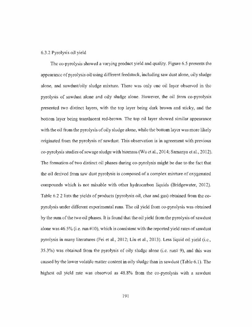
6.3 .2 Pyrolysis oil yield
The co-pyrolysis showed a varying product yield and quality. Figure 6.5 presents the
appearance of pyrolysis oil using different feedstock, including saw dust alone, oily sludge
alone, and sawdust/oily sludge mixture. There was only one oil layer observed in the
pyrolysis of sawdust alone and oily sludge alone. However, the oil from co-pyrolysis
presented two distinct layers, with the top layer being dark brown and sticky, and the
bottom layer being translucent red-brown. The top oil layer showed similar appearance
with the oil from the pyrolysis of oily sludge alone, while the bottom layer was more likely
originated from the pyrolysis of sawdust. This observation is in agreement with previous
co-pyrolysis studies of sewage sludge with biomass (Wu et al., 2014; Samanya et al., 2012).
The formation of two distinct oil phases during co-pyrolysis might be due to the fact that
the oil derived from saw dust pyrolysis is composed of a complex mixture of oxygenated
compounds which is not mixable with other hydrocarbon liquids (Bridgewater, 2012).
Table 6.2 2 lists the yields of products (pyrolysis oil, char and gas) obtained from the co-
pyrolysis under different experimental runs. The oil yield from co-pyrolysis was obtained
by the sum of the two oil phases. It is found that the oil yield from the pyrolysis of sawdust
alone was 46.5% (i.e. run #10), which is consistent with the reported yield rates of sawdust
pyrolysis in many literatures (Fei et al., 2012; Liu et al., 2013). Less liquid oil yield (i.e.,
35.3%) was obtained from the pyrolysis of oily sludge alone (i.e. run# 9), and this was
caused by the lower volatile matter content in oily sludge than in sawdust (Table 6.1 ). The
highest oil yield rate was observed as 48 .8% from the co-pyrolysis with a sawdust
191
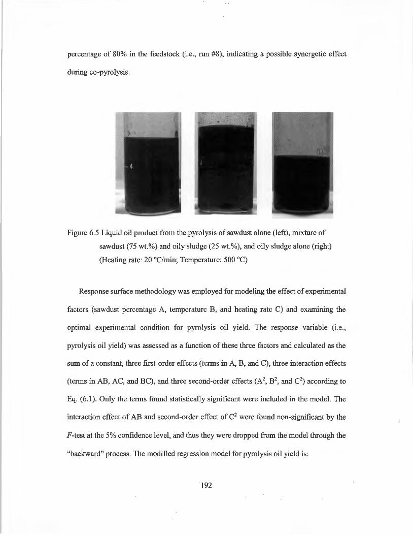
percentage of 80% in the feedstock (i.e., run #8), indicating a possible synergetic effect
during co-pyrolysis.
Figure 6.5 Liquid oil product from the pyrolysis of sawdust alone (left), mixture of
sawdust (75 wt.%) and oily sludge (25 wt.%), and oily sludge alone (right)
(Heating rate: 20 °C/min; Temperature: 500 °C)
Response surface methodology was employed for modeling the effect of experimental
factors (sawdust percentage A, temperature B, and heating rate C) and examining the
optimal experimental condition for pyrolysis oil yield. The response variable (i.e.,
pyrolysis oil yield) was assessed as a function of these three factors and calculated as the
sum of a constant, three first-order effects (terms in A, B, and C), three interaction effects
(terms in AB, AC, and BC), and three second-order effects (A2, B2, and C2) according to
Eq. (6.1). Only the terms found statistically significant were included in the model. The
interaction effect of AB and second-order effect of C2 were found non-significant by the
F-test at the 5% confidence level, and thus they were dropped from the model through the
"backward" process. The modified regression model for pyrolysis oil yield is:
192

Runs
1
2
3
4
5
Y0 = -102.85 + 0.104A + 0.498 + 2.0SC + O.OlAC - 5.09 x 10⁻³ BC - 1.46 x
Eq. (6.3)
Where Y0 is the yield of pyrolysis oil (%), A represents the mass percentage of
sawdust in feedstock (%), B is the pyrolysis temperature (0 C), and C is the heating rate
(°C/min).
Table 6.3 presents the statistical parameters obtained from ANOV A for the developed
regression model. The model was significant based on F-test at 5% confidence level (P <
0.05). The adjusted R2 coefficient was well within the acceptable range of R2 > 0.9,
indicating a satisfactory adjustment of the quadratic regression model. The lack of fit was
not significant (P > 0.05), indicating that the fitness of model was robust. High predicted
R2 value means the developed response surface model can be used as a predictive tool over
the whole parameter uncertainty range. The optimal oil yield condition was set as heating
20 g sawdust to 500 °C at a heating rate of 20 °C/min.
Table 6.2 Experimental array of CCC design for co-pyrolysis experiments and product
yield results
Sawdust ratio in Temperature a Heating rate a Pyrolysis oil Char yield Gas yield
feedstock a (wt.%) (QC) (°C/ min) yield(%) (%) (%)
(-1) 20 (-1) 440 (-1) 8 35.8 19.7 44.5
(1) 80 (-1) 440 (-1) 8 40.3 24.2 35.5
(-1) 20 (1) 560 (-1) 8 41.4 15.2 43.4
(1) 80 (1) 560 (-1) 8 46.2 17.6 36.2
(-1) 20 (-1) 440 (1) 17 36.6 19.8 43.6
193
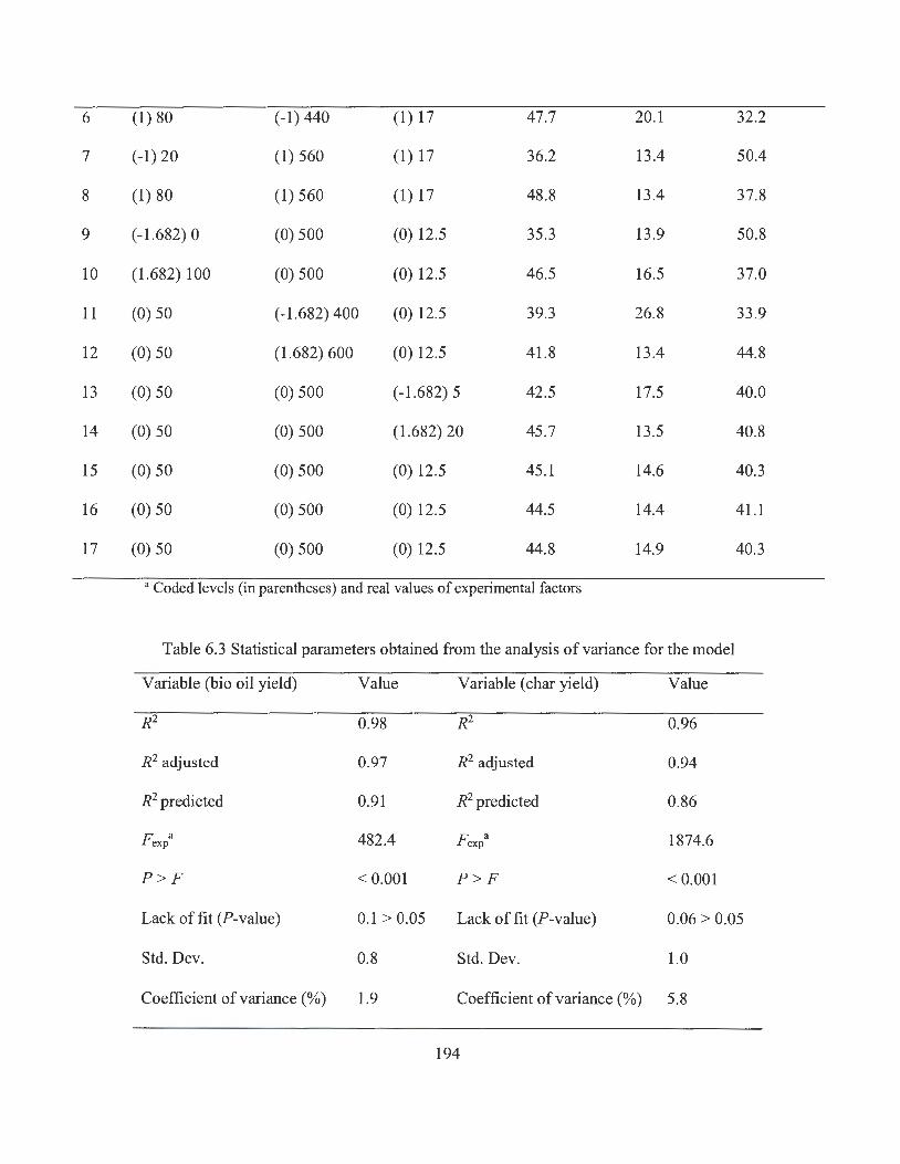
6 (1) 80 (-1) 440 (1) 17 47.7 20.1 32.2
7 (-1) 20 (1) 560 (1) 17 36.2 13.4 50.4
8 (1) 80 (1) 560 (1) 17 48.8 13.4 37.8
9 (-1.682) 0 (0) 500 (0) 12.5 35.3 13.9 50.8
10 (1.682) 100 (0) 500 (0) 12.5 46.5 16.5 37.0
11 (0) 50 (-1.682) 400 (0) 12.5 39.3 26.8 33.9
12 (0) 50 (1.682) 600 (0) 12.5 41.8 13.4 44.8
13 (0) 50 (0) 500 (-1.682) 5 42.5 17.5 40.0
14 (0) 50 (0) 500 (1.682) 20 45.7 13.5 40.8
15 (0) 50 (0) 500 (0) 12.5 45.1 14.6 40.3
16 (0) 50 (0) 500 (0) 12.5 44.5 14.4 41.1
17 (0) 50 (0) 500 (0) 12.5 44.8 14.9 40.3
• Coded levels (in parentheses) and real values of experimental factors
Table 6.3 Statistical parameters obtained from the analysis of variance for the model
Variable (bio oil yield) Value Variable ( char yield) Value
R2 0.98 R2 0.96
R2 adjusted 0.97 R2 adjusted 0.94
R2 predicted 0.91 R2 predicted 0.86
F exp a 482.4 F exp a 1874.6
P > F < 0.001 P > F < 0.001
Lack of fit (P-value) 0.1 > 0.05 Lack of fit (P-value) 0.06 > 0.05
Std. Dev. 0.8 Std. Dev. 1.0
Coefficient of variance(%) 1.9 Coefficient of variance(%) 5.8
194

Press
Adequate precision
28.1
25.1
Press
Adequate precision
• F exp is the ratio of the mean square of the model to mean square of the error.
35.4
23 .8
The simulated main effects of the three experimental factors on pyrolysis oil yield are
illustrated in Figure 6.6. It can be found that the increase of sawdust percentage in
feedstock could have a positive effect on the yield of pyrolysis oil. Generally, a higher
sawdust percentage led to a higher pyrolysis oil yield, but further increase of this
percentage only brought limited increase in oil yield. In fact, the highest oil yield rate of
48.8% during experiments was associated with a sawdust percentage of 80% (Table 6.2).
The temperature illustrated a differing effect from sawdust percentage. As shown in Figure
6.6b, both too high and too low pyrolysis temperature showed a negative effect on oil yield,
with the optimal temperature being in the range of 500-550 °C, while the oil yield declined
by about 3% as the temperature increased from 500 to 600 °C. This might be because of
the fact that a small part of organic matter in sawdust and oily sludge cannot completely
decompose at a temperature lower than 400 °C (Biagini et al. , 2006; Akhtar and Amin,
2012), while a higher temperature (> 600 °C) could result in secondary decomposition
during which the liquid oil is further decomposed into non-condensable gaseous products
(Shen and Gu, 2009). A number of literatures also reported that the maximum liquid oil
yield from biomass pyrolysis often occurred in the temperature range of 500-550 °C
(Akhtar and Amin, 2012). The yield of bio-oil declined about 3% as the temperature
increased from 500 to 600 °C. High temperature (> 600 °C) could result in secondary
decomposition, during which the liquid oil is further decomposed into non-condensable
gas products (Shen and Gu, 2009). The effect of heating rate was positive on the yield of
195

pyrolysis oil. As shown in Figure 6.6c, a higher heating rate was preferred for producing
pyrolysis oil, with oil yield being increased from 41.1 % to 45. 7% as heating rate increased
from 5 to 20 °C/ min. The positive effect of high heating rate is mainly due to the short
time available for secondary decomposition of condensable gases (Akhtar and Amin,
2012). It was found from statistical analysis that all three experimental factors played a
major role in the process of pyrolysis oil production.
The interaction effect of experimental factors on pyrolysis oil yield was shown in
Figure 6.7. The interaction of sawdust percentage and pyrolysis temperature was not
included because this effect was not significant according to statistical analysis. As shown
in Figure 6. 7a, low heating rate and low pyrolysis temperature could result in low pyrolysis
oil yield. Increasing heating rate from 5 to 20 °C/min could enhance the oil yield in
treatments with a temperature lower than 500 °C. However, when the treatment
temperature exceeded 550 °C, high heating rate (i.e. 20 °C/min) could pose a negative
effect on pyrolysis oil production. The interaction effect of sawdust percentage and heating
rate was illustrated in Figure 6.7b. It was found that high heating rate was preferred in the
treatments with a sawdust percentage higher than 50%; however, high heating rate could
compromise the oil yield in the treatments which had a low sawdust percentage (i.e., <
25%). This might be because at high heating rate, light PHCs fractions in oily sludge were
quickly decomposed into organic vapor which cannot be involved in polymerization
reactions to form condensable gaseous products, and thus leading to a low yield of oil
products.
196
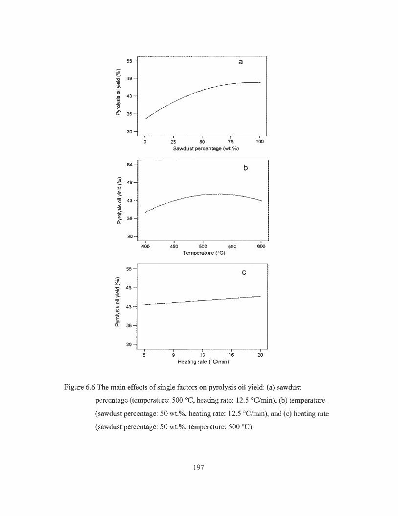
55 a -;§!. 0
:2 49 ·~ 'i5
"' 43 'iii .?:-e >, a.. 36
30
0 25 50 75 100 Sawdust percentage (wt.%)
54 b -~ ~ 49 "O al ·;;:. ·o 43 "' 'iii >,
~ 36 6:
30
400 450 500 550 600 Temperature (°C}
55 C -~
'C 49 a:; ·;;;. ·o "' 43 'iii >, e >, 0.. 36
30
5 9 13 16 20 Heating rate (°C/min)
Figure 6.6 The main effects of single factors on pyrolysis oil yield: (a) sawdust
percentage (temperature: 500 °C, heating rate: 12.5 °C/min), (b) temperature
(sawdust percentage: 50 wt.%, heating rate: 12.5 °C/min), and (c) heating rate
(sawdust percentage: 50 wt.%, temperature: 500 °C)
197

60 a -~ 0 _.. 53 "O (I.) ·;;, 45 ·5
"' 38 'ci> >-0 30 ,._ >-a..
600
Heating rate (°C/rnin ) 5 400 Temperature (°C)
60 ........ ~ 0 _..
53 "O (I.) ·;;, 45 ·o "' 38 'ci, >-e >, a.
Heating rate (°C/rn in) 5 0 Sawdust (wt.%)
Figure 6. 7 The interaction effect of experimental factors on pyrolysis oil yield
6.3 .3 Pyrolysis char yield
Solid char is another valuable product from waste pyrolysis treatment. The modified
regression model for char yield (Ye, %) from co-pyrolysis was obtained as follows:
Ye= 178.17 + 0.11A- 0.608 + 0.03C- 6.17 X 10⁻³AC + 5.43 X 10⁻⁴ 8 2 (6.4)
198

Table 6.3 lists the statistical parameters obtained from ANOV A for the char yield model.
The model was significant by F-test at the 5% confidence level (P < 0.05). The lack of fit
was not significant (P > 0.05), indicating that the fitness of model is acceptable. The main
effects of experimental factors on char yield are shown in Figure 6.8. Generally, char yield
increased with sawdust percentage because sawdust had higher fixed carbon content than
oily sludge. However, the pyrolysis temperature showed a negative effect on char yield,
and a higher pyrolysis temperature could lead to a lower char yield as a result of better
biomass conversion due to primary reactions of pyrolysis (Uzun et al. , 2006). These
primary reactions include decomposition of cellulose, hemicellulose, and lignin in sawdust
(Xiu and Shahbazi, 2012). Moreover, high temperature could facilitate the secondary
decomposition of char to generate non-condensable gaseous products (Xiu and Shahbazi,
2012; Menendez et al. , 2004; Canel et al. , 2004). Similar to pyrolysis temperature, a higher
heating rate led to a lower char yield. This might be due to the fact that rapid heating can
enhance the abundance of volatiles by fast decomposition of sawdust, resulting in fast
removal of high molecular volatiles and thus leaving low char amounts (Akhtar and Amin,
2012).
Figure 6.9 presents the interaction effect of experimental factors on char yield. Only
the interaction effect of heating rate and sawdust percentage on char yield was found
significant. It can be found that a high heating rate showed little effect on the char
production in the treatments with relatively low sawdust percentage. However, a high
heating rate could pose a significant negative effect on char yield when the sawdust
percentage was high. A higher heating rate could lead to lower oil yield but higher char
yield in the treatments with lower sawdust percentage (i.e. , < 25%), but could result in
199
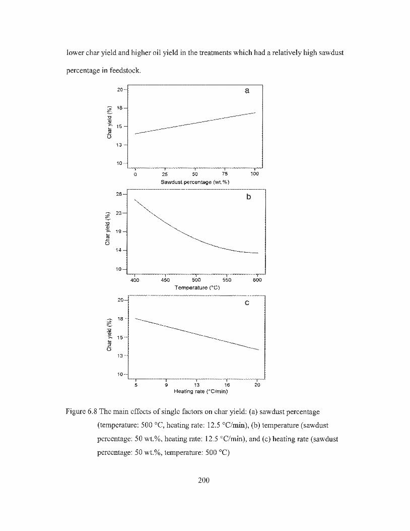
lower char yield and higher oil yield in the treatments which had a relatively high sawdust
percentage in feedstock.
20 a
-- 18 ~ "O w ·;;:.. 15 .... Ill .r:: (.)
13
10
0 25 50 75 100
Sawdust percentage (wt.%)
28 b ,._ 23 C 32 (I) ·s:. 19 ... C'II .r:: (.)
14
10
400 450 500 550 600 Temperature (°C)
20 C
.-.. ~
18
3:! (I) ·;;:.. 15 ... C'II .r:: u
13
10
5 9 13 16 20 Heating rate (°C/min)
Figure 6.8 The main effects of single factors on char yield: (a) sawdust percentage
(temperature: 500 °C, heating rate: 12.5 °C/min), (b) temperature (sawdust
percentage: 50 wt.%, heating rate: 12.5 °C/min), and (c) heating rate (sawdust
percentage: 50 wt.%, temperature: 500 °C)
200

30
- 25 ~ 0 -"O 20 Q) ·5>-L.
15 cu ..c. (.)
10
0
Heating rate (°C/min) 5 0 Sawdust (wt.%)
Figure 6.9 The interaction effect of experimental factors on char yield
6.3.4 Synergistic effect of co-pyrolysis on oil yield
In order to investigate the synergistic effect of co-pyrolysis, the product yield rate was
further evaluated using various sawdust percentages at a pyrolysis temperature of 500 °C
and a heating rate of 20 °C/min. Table 6.4 lists the observed and predicted pyrolysis
product yields, while the prediction was obtained from Eq. (6.2). The actual oil yield rate
from the pyrolysis of oily sludge alone and sawdust alone were 36.2% and 49.2%,
respectively. Oily sludge generated the highest amount of non-condensable gaseous
products. It can be found that the oil yield was increased by 3-4% as compared to the
predicted yield in co-pyrolysis treatments with a sawdust percentage higher than 40%,
suggesting the presence of synergetic effect during co-pyrolysis (Onal et al. , 2014). For
example, the actual oil yield rate of co-pyrolysis treatment was 48.9% when sawdust /oily
201
sludge mass ratio was 3: 1, which is higher than the predicted yield (i.e., 46.0% ). At a mass
ratio of 1: 1, the actual oil yield reached 46.4%, which is also higher than the predicted
yield rate of 42. 7%. However, the synergetic effect was not obvious in co-pyrolysis
treatments with a sawdust percentage of lower than 50%, with the difference between
observed and predicted oil yield being less than 1 %. The synergistic effect of co-pyrolysis
on char yield was not obvious, but less gaseous products were obtained in co-pyrolysis
treatments at a sawdust percentage of higher than 50% as compared to the predicted value,
indicating that the increase in oil yield might be at the cost of gas yield. It can be found
from Table 6.4 that the enhancement in total oil yield from co-pyrolysis was mainly
attributed to the increase of bottom layer oil, indicating that adding oily sludge into sawdust
could result in better biomass conversion. Zuo et al. (2014) studied the co-pyrolysis of
sawdust and sewage sludge, and they also observed an increase in total oil yield which was
mainly contributed by the increase of bottom oil. Song et al. (2014) investigated the co-
pyrolysis of pine sawdust and lignite, and found that the experimental oil yield rate was
higher than that of calculated value in the treatment of a mixed feedstock (i.e., 20% of
lignite and 80% of sawdust) at 600 °C. They suggested that the synergetic effect can be
attributed to the different H/C and 0 /C molar ratios in two materials and the catalytic effect
of some alkali and alkaline metallic species in lignite (Song et al., 2014). High H/C and
0 /C molar ratios can facilitate the generation of radicals such as hydroxyl which can act
as hydrogen donors, promoting the cracking of heavy weight aromatic and aliphatic
compounds in oily sludge (Conesa et al., 2014; Song et al., 2014; Chen et al., 2014). Some
radicals could combine with others to form aldehydes, carboxylic acids, and ketones, and
thus increase the yield of bottom oil (Zuo et al., 2014).
202
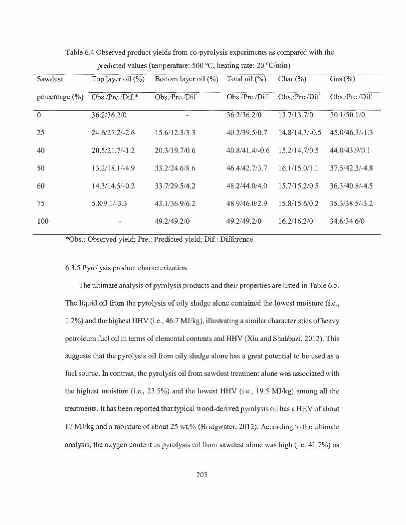
Table 6.4 Observed product yields from co-pyrolysis experiments as compared with the
predicted values (temperature: 500 °C, heating rate: 20 °C/min)
Sawdust Top layer oil(%) Bottom layer oil (%) Total oil(%) Char(%) Gas(%)
percentage (%) Obs./Pre./Dif. * Obs./Pre./Dif. Obs./Pre./Dif. Obs./Pre./Dif. Obs./Pre./Dif.
0
25
40
50
60
75
100
36.2/36.2/0 36.2/36.2/0 13.7/13.7/0 50.1/50.1/0
24.6/27.2/-2.6 15.6/12.3/3.3 40.2/39.5/0.7 14.8/14.3/-0.5 45.0/46.3/-1.3
20.5/21.7/-1.2 20.3/19.7/0.6 40.8/41.4/-0.6 15.2/14.7/0.5 44.0/43.9/0.1
13.2/18.1/-4.9 33.2/24.6/8.6 46.4/42. 7 /3. 7 16.1 /15.0/1.1 37.5/42.3/-4.8
14.3/14.5/-0.2 33.7/29.5/4.2 48.2/44.0/4.0 15.7/15.2/0.5 36.3/40.8/-4.5
5.8/9.1 /-3 .3 43 .1/36.9/6.2 48.9/46.0/2.9 15.8/15 .6/0.2 35.3/38.5/-3.2
49.2/49.2/0 49.2/49.2/0 16.2/16.2/0 34.6/34.6/0
*Obs.: Observed yield; Pre.: Predicted yield; Dif.: Difference
6.3.5 Pyrolysis product characterization
The ultimate analysis of pyrolysis products and their properties are listed in Table 6.5.
The liquid oil from the pyrolysis of oily sludge alone contained the lowest moisture (i.e.,
1.2%) and the highest HHV (i.e., 46.7 MJ/kg), illustrating a similar characteristics of heavy
petroleum fuel oil in terms of elemental contents and HHV (Xiu and Shahbazi, 2012). This
suggests that the pyrolysis oil from oily sludge alone has a great potential to be used as a
fuel source. In contrast, the pyrolysis oil from sawdust treatment alone was associated with
the highest moisture (i.e., 23.5%) and the lowest HHV (i.e., 19.5 MJ/kg) among all the
treatments. It has been reported that typical wood-derived pyrolysis oil has a HHV of about
17 MJ/kg and a moisture of about 25 wt.% (Bridgwater, 2012). According to the ultimate
analysis, the oxygen content in pyrolysis oil from sawdust alone was high (i.e. 41.7%) as
203
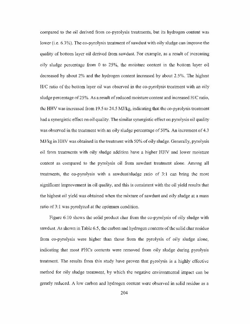
compared to the oil derived from co-pyrolysis treatments, but its hydrogen content was
lower (i.e. 6.3%). The co-pyrolysis treatment of sawdust with oily sludge can improve the
quality of bottom layer oil derived from sawdust. For example, as a result of increasing
oily sludge percentage from O to 25%, the moisture content in the bottom layer oil
decreased by about 2% and the hydrogen content increased by about 2.5%. The highest
H/C ratio of the bottom layer oil was observed in the co-pyrolysis treatment with an oily
sludge percentage of25%. As a result of reduced moisture content and increased H/C ratio,
the HHV was increased from 19.5 to 24.5 MJ/kg, indicating that the co-pyrolysis treatment
had a synergistic effect on oil quality. The similar synergistic effect on pyrolysis oil quality
was observed in the treatment with an oily sludge percentage of 50%. An increment of 4.3
MJ/kg in HHV was obtained in the treatment with 50% of oily sludge. Generally, pyrolysis
oil from treatments with oily sludge addition have a higher HHV and lower moisture
content as compared to the pyrolysis oil from sawdust treatment alone. Among all
treatments, the co-pyrolysis with a sawdust/sludge ratio of 3: 1 can bring the most
significant improvement in oil quality, and this is consistent with the oil yield results that
the highest oil yield was obtained when the mixture of sawdust and oily sludge at a mass
ratio of 3: 1 was pyrolyzed at the optimum condition.
Figure 6: 10 shows the solid product char from the co-pyrolysis of oily sludge with
sawdust. As shown in Table 6.5, the carbon and hydrogen contents of the solid char residue
from co-pyrolysis were higher than those from the pyrolysis of oily sludge alone,
indicating that most PHCs contents were removed from oily sludge during pyrolysis
treatment. The results from this study have proven that pyrolysis is a highly effective
method for oily sludge treatment, by which the negative environmental impact can be
greatly reduced. A low carbon and hydrogen content were observed in solid residue as a
204
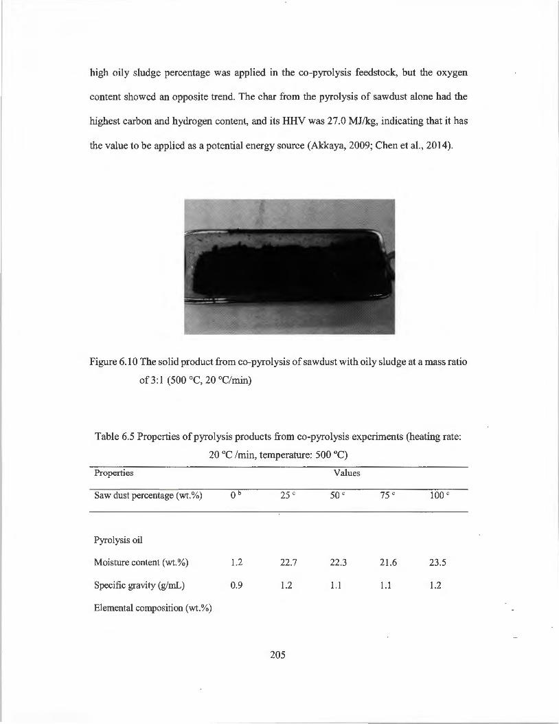
high oily sludge percentage was applied in the co-pyrolysis feedstock, but the oxygen
content showed an opposite trend. The char from the pyrolysis of sawdust alone had the
highest carbon and hydrogen content, and its HHV was 27.0 MJ/kg, indicating that it has
the value to be applied as a potential energy source (Akkaya, 2009; Chen et al., 2014).
Figure 6.10 The solid product from co-pyrolysis of sawdust with oily sludge at a mass ratio
of3:l (500 °C, 20 °C/min)
Table 6.5 Properties of pyrolysis products from co-pyrolysis experiments (heating rate:
20 °C /min, temperature: 500 °C)
Properties
Saw dust percentage (wt.%)
Pyrolysis oil
Moisture content (wt.%)
Specific gravity (g/mL)
Elemental composition (wt.%)
1.2
0.9
25 C
22.7
1.2
205
Values
50 C
22.3
1.1
75 C
21.6
1.1
100 C
23.5
1.2
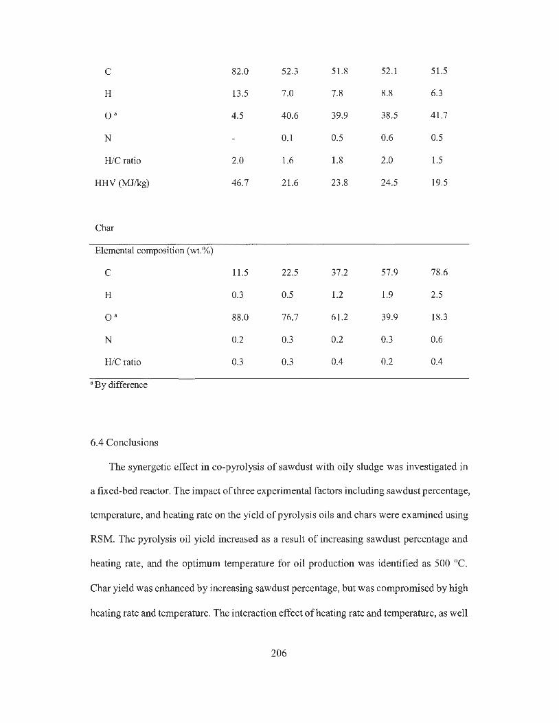
C 82.0 52.3 51.8 52.1 51.5
H 13 .5 7.0 7.8 8.8 6.3
o · 4.5 40.6 39.9 38.5 41.7
N 0.1 0.5 0.6 0.5
H/C ratio 2.0 1.6 1.8 2.0 1.5
HHV (MJ/kg) 46.7 21.6 23.8 24.5 19.5
Char
Elemental composition (wt.%)
C 11.5 22.5 37.2 57.9 78.6
H 0.3 0.5 1.2 1.9 2.5
o · 88.0 76.7 61.2 39.9 18.3
N 0.2 0.3 0.2 0.3 0.6
H/C ratio 0.3 0.3 0.4 0.2 0.4
• By difference
6.4 Conclusions
The synergetic effect in co-pyrolysis of sawdust with oily sludge was investigated in
a fixed-bed reactor. The impact of three experimental factors including sawdust percentage,
temperature, and heating rate on the yield of pyrolysis oils and chars were examined using
RSM. The pyrolysis oil yield increased as a result of increasing sawdust percentage and
heating rate, and the optimum temperature for oil production was identified as 500 °C.
Char yield was enhanced by increasing sawdust percentage, but was compromised by high
heating rate and temperature. The interaction effect of heating rate and temperature, as well
206
as heating rate and sawdust percentage, were significant on pyrolysis oil yield. The
synergetic effect can bring about 4% increase in yield of bottom layer oil derived from co-
pyrolysis treatment as compared to the predicted value, but no obvious effect on char yield
was observed. Co-pyrolysis of sawdust with oily sludge at a sawdust percentage higher
than 40% can improve the quality of bottom layer oil by increasing its H/C ratio and HHV.
Pyrolysis oil from individual oily sludge treatment had the highest HHV and the lowest
moisture. High sawdust percentage in the mixture feedstock also can improve the quality
of char product by increasing its carbon content. The results confirmed that using oily
sludge as an additive in sawdust pyrolysis could improve pyrolysis oil production, and thus
the co-pyrolysis treatment could be a promising way for the disposal of hazardous oily
sludge.
207
Chapter 7 Conclusions and future research
7.1 Thesis conclusions
The purpose of this thesis was to develop combined oil recovery techniques for the
treatment of various refinery oily sludges. In doing so, four oil recovery approaches
including ultrasonic irradiation, solvent extraction, freeze/thaw, and pyrolysis were
selected. The oil recovery performance of different approaches was improved by
combining single treatment approach with each other for increasing the oil recovery rate,
reducing the treatment duration, and improving the quality of recovered oil as value-added
products.
The results of this study have demonstrated that using novel oil recovery techniques
can effectively handle complex oily sludge from different sources in petroleum refining
industries. These combined treatment methods have great potential to be commercialized
and applied in practical oily wastes treatment in order to reduce the environmental risks
posed by hazardous oily sludge. The followings are the major conclusions of this thesis.
7.1.1 The oil recovery and desalting effect of ultrasonic irradiation on oily sludge
In Chapter 3, the oil recovery and desalting effect of ultrasonic irradiation on refinery
tank bottom sludge was investigated. The impact of influential factors including ultrasonic
power, treatment duration, sludge-to-water (S/W) ratio, and sludge-water slurry
temperature on the treatment performance were studied. It can be concluded that ultrasonic
irradiation showed effective oil recovery and desalting effect on refinery tank bottom
sludge. During the treatment process, the temperature of the oily sludge-water mixture
208
increased as a result of ultrasonic irradiation. At an ultrasonic power of 75 W, the slurry
temperature increased from 25 to 77 °C within 6 min of irradiation. In comparison, the
slurry temperature increased from 25 to 61 °C within 6 min as an ultrasonic power of 21
W was applied.
Direct heating was able to recover part of the oil from oily sludge and also reduce the
salt content in recovered oil. When the bulk temperature of oily sludge-water slurry
mixture rose to 80 °C by direct heating, an oil recovery rate of 32.9% and a salt content of
6.0 mg/L in recovered oil were obtained. Under the same conditions, the lowest TPH
concentration and highest salt content were found to be 533 .3 mg/Land 159.8 mg/Lin the
separated wastewater as by-product.
Low ultrasonic power (i.e. , 21 W) and short irradiation duration (2 min) were not
effective for oil recovery from oily sludge. Under an ultrasonic power of 48 W, PHC
recovery significantly increased from 35.7% to 61.2% as the irradiation duration extended
from 2 to 8 min. The highest PHC recovery was 62.2% in the treatment with an ultrasonic
power of 7 5 W and treatment duration of 6 min. Further extended the duration could cause
decrease in PHC recovery.
The optimal sludge-to-water ratio was found to be 1 :4, yet too high or too low water
content in the sludge slurry system led to lower oil recovery rate. It was found that the salt
content in recovered oil was decreased to less than 5 mg/L after 6 min of ultrasonic
irradiation at a power of 75 W, which can meet the salt content requirement for feedstock
oil in most refineries. The separated wastewater from ultrasonic irradiation contained
relatively high concentrations of TPH (i.e., 1044 mg/L) and salt (i.e. , 588 mg/L) which
require proper treatment.
209

The recovered oil contained about 80.4% TPH which is higher than in crude oil (i.e.,
71.7%). Its TPH contained similar percentages of F2, F3 and F4 fractions as the original
sludge, which implies that ultrasonic irradiation did not cause the degradation of PHCs
fractions in oily sludge.
7 .1.2 The combined effect of ultrasonic irradiation and solvent extraction on oil recovery
In Chapter 4, the oil recovery effect of two UAE systems including ultrasonic assisted
extraction probe (UAEP) system and ultrasonic assisted extraction bath (UAEB) system
on tank bottom sludge was examined as compared to that of mechanical shaking extraction
(MSE) treatment.
Results showed that solvent type, SIS ratio, extraction duration, and shaking speed
have had significant influence on oil recovery in MSE treatment. The highest oil recovery
of CHX, EA, and MEK were 63 .7%, 35.2%, and 34.8%, respectively when the SIS ratio
was 4: 1, extraction duration was 60 min, and shaking speed was 250 rpm. Solvent type has
the most influence on oil recovery, followed by shaking speed, extraction duration, and
SIS ratio. More than 70% of solvent can be recovered after MSE treatment, and the highest
solvent recovery of 83.3% was observed in MEK. Using a higher SIS ratio also results in
a higher solvent recovery rate. As the increase of SIS ratio from 2:1 to 4:1, the solvent
recovery rate increased from 72.8% to 83.1 % accordingly.
In UAEP treatment, SIS ratio, treatment duration and ultrasonic power have had
significant effects on oil recovery. The highest oil recovery obtained by CHX was 59.8%
under the conditions of ultrasonic power of 21 W, SIS ratio of 4: 1, and treatment duration
of 21 s, which was higher than MSE. The extraction using MEK also can be improved by
UAEP with the highest oil recovery of38.3% as compared to 33.3% ofMSE. Among four
factors, ultrasonic power showed insignificant influence on oil recovery while the effects
210
of other three factors were significant. The effects of treatment duration and ultrasonic
irradiation power on solvent recovery were not significant, indicating that UAEP could not
cause negative influence on solvent recovery because solvent recovery of UAEP was
generally higher than that of MSE treatment.
In UAEB treatment, the highest oil recovery of 62.6% can be found in the treatment
using CHX. The influence of four factors on oil recovery were in an order of solvent type >
SIS ratio > treatment duration > bath temperature. The optimum condition for oil recovery
was using solvent of CHX, ultrasonic duration of 15 min, and S/S ratio of 4: 1. Among four
experimental factors, bath temperature showed insignificant effect on oil recovery.
However, bath temperature showed a significant negative effect on the solvent recovery.
The results showed that two extractions of the three treatment processes could be
sufficient to achieve a satisfactory oil recovery. Among the three solvents, CHX was
associated with the highest TPH recovery for each extraction process. The TPH in
recovered oil from UAEP treatment were generally higher than these of MSE treatment.
However, the analysis on the properties of recovered oil showed that the TPH content of
recovered oil using CHX was the lowest. Recovered oil from three treatments mainly
consisted of F2 and F3 fractions, while there was also significant amount ofF4 fraction in
the recovered oil by CHX. Results also showed that no degradation effect on PHCs by
UAE process since the distribution of PH Cs in recovered oil by UAE process was similar
to that of original oily sludge.
Recovered oil by MEK and EA presented higher quality than that by CHX. Recovered
oil also showed higher density, carbon residue, and viscosity as compared to crude oil. The
calorific value of recovered oil by MEK and EA was also higher than that of crude oil. The
asphaltene content in recovered oil by MEK and EA were lower than crude oil, which is
211
more preferable for downstream refining process. Results showed that UAE could be a fast
and effective oil recovery method for refinery oily sludge treatment.
7.1.3 The combined effect of solvent extraction and freeze/thaw on oil recovery
In Chapter 5, a combinational solution of solvent extraction and freeze/thaw was
developed for the oil recovery from high moisture dredged sludge from refinery
wastewater pond. The oil recovery rate, solvent recovery rate, and the waste reduction rate
of five solvents including CHX, EA, MEK, DCM, and 2-Pro were examined. The
performance of freeze thaw treatment on improving the quality of recovered oil in terms
of its TPH content was evaluated. The properties of solid residue as the by-product of the
treatment process were also investigated.
It was found that 2-Pro was associated with a much lower oil recovery than the other
four solvents, while CHX was associated with the highest oil recovery rate. The oil
recovery rate of CHX, DCM, MEK, EA, and 2-Pro reached up to 42.4%, 37.7%, 37.2%,
37.6%, and 17.1 %, respectively when the solvent-to-sludge ratio was 4: 1. For all solvents
except DCM, the oil recovery rate increased with the extraction duration until reaching
equilibrium at the extraction duration of 30 min.
The solvent recovery rate after oil extraction generally increased with the solvent-to-
sludge ratio. The CHX extraction treatment was associated with a considerable increase of
solvent recovery rate from 51.2% to 81.3% when the ratio increased from 1:1 to 4:1. All
the solvents except DCM showed satisfactory solvent recovery rate, with the highest
solvent recovery rate of only 48.5% for DCM but higher than 80% for the other four
solvents. The effect of extraction duration on the solvent recovery was not significant.
More than 50% of original oily sludge mass was reduced in all the treatments. It is
noted that the waste reduction rate for DCM extraction was the highest (i.e. 80%) among
212
all the treatments. The waste reduction rate increased from 50. 7% to 64.1 % (CHX), 56.3%
to 61.5% (MEK), 53 .2% to 66.4% (EA), and 49.3% to 57.2% (2-Pro) as the solvent-to-
sludge ratio increased from 1: 1 to 4: 1, respectively. The extraction duration illustrated little
effect on the variation of waste reduction rate when using CHX, MEK, EA, and 2-Pro
extraction. For DCM extraction, the waste reduction increased from 62.6% to 77.7% as
the extraction duration increased from 5 min to 30 min when the equilibrium was reached.
It was also found that under the optimum extraction conditions (SIS ratio of 4: 1 and
duration of 30 min), the oil recovery rate generally increased with the solvent extraction
cycles. After one solvent extraction cycle, CHX achieved a higher oil recovery (i.e., 41.0%)
as compared to that of MEK (i.e. 35.4%) and EA (i.e. 35.8%). After the second extraction,
the oil recovery rate increased to 56.0% (CHX), 40.4% (MEK), and 38.3% (EA),
respectively. There was only trivial increment in oil recovery as the third extraction applied,
indicating that only one or two extractions cycles could be enough for the study sludge.
Individual FIT treatment was not effective for oil recovery from refinery wastewater
pond sludge. However, FIT treatment can remove the emulsified water from the extractant
using MEK and EA as extraction solvents. The combined solvent extraction with FIT
treatment can significantly increase the TPH content in the recovered oil for both MEK
and EA extractions. With FIT treatment, the TPH content in the recovered oil increased
from 41.8% to 62.6% when using MEK extraction and from 41.0% to 58.8% when using
EA extraction. The improvement of FIT treatment on TPH content in the recovered oil by
CHX extraction was not significant. The increase ofTPH in the recovered oil by increased
number of FIT cycles were not significant for each solvent, showing that one FIT cycle
would be sufficient for the dewatering of extractant obtained from the high-moisture
petroleum sludge.
213
The F2, F3, and F4 fractions accounted for 26.5%, 69.1%, and 4.3% ofTPH in the
recovered oil by CHX extraction with freeze/thaw. On the other hand, the F2 and F3
fractions in the oil recovered by the combination of MEK or EA extraction with
freeze/thaw treatment were slightly higher, while the F4 fraction was lower than that from
CHX extraction. In comparison to crude oil, the recovered oil from the study sludge
contained more F3 fraction but less F2 fraction.
Although solvent extraction showed obvious effect on oil recovery from the oily
sludge, the TPH content in the solid residue was still much higher than the clean-up level.
Solvent extraction with FIT treatment had little removal effect on heavy metals in oily
sludge, and most heavy metals were remained and accumulated in the solid residues,
indicating that the solid residues from this treatment require proper management.
7.1.4 The co-pyrolysis of sawdust with oily sludge for pyrolysis oil production
In Chapter 6, the synergetic effect in co-pyrolysis of sawdust with oily sludge was
investigated in a fixed-bed reactor. The impact of three experimental factors including
sawdust percentage, temperature, and heating rate on the yield of pyrolysis oils and chars
were examined using RSM. The characteristics of products from the co-pyrolysis were
determined to evaluate their possibility of being a potential energy source and
petrochemical feedstock.
According to the TGA, the decomposition behavior of sawdust can be divided into
three stages: ambient to 110, 110 to 700, and 700 to 900 °C, and the decomposition of oily
sludge can be divided into four stages: ambient to 110, 110-150, 150-550, and 550 to
900 °C. The maximum weight loss of sawdust and oily sludge was observed at 350 °C and
150 °C, respectively.
214
The oil product from the co-pyrolysis of sawdust with oily sludge had two layers. The
top layer was mainly from the pyrolysis of oily sludge alone and the bottom layer was
derived from sawdust pyrolysis alone. The oil yield of sawdust pyrolysis alone was 46.5%,
while the pyrolysis of oily sludge alone can generate 35. 7% of liquid oil. The highest oil
yield rate was 48.8% from the co-pyrolysis of sawdust with oily sludge with a sawdust
percentage of 80%, which was higher than the pyrolysis of sawdust or oily sludge alone.
Two quadratic models were developed for investigating the main and interaction
effect of experimental factors on oil and char yield in co-pyrolysis treatment. The model
for predicting pyrolysis oil production was: Oil yield(%)= -102.85 + 0.104A + 0.49B +
2.0SC + O.OlAC - 5.09 X 10⁻³ BC - 1.46 X 10⁻³ A2 - 4.06 X 10⁻⁴ 0 2 and for predicting char
yield was: Char yield (%) = 178.17 + O.llA- 0.60B + 0.03C- 6.17 x 10⁻³AC + 5.43 x
10-4 0 2 . The A, B, and C represent sawdust percentage (wt.%), temperature (cC), and
heating rate (cC/min). Both models were robust and showed good fit to experimental
results.
The main effect of experimental factors showed that sawdust percentage had a
positive effect on pyrolysis oil yield. Generally, pyrolysis oil yield increased with the
increase of sawdust percentage in feedstock. Both too high and too low temperature
showed a negative effect on oil yield and the optimal temperature for pyrolysis oil
production was 500 cc. A higher heating rate was also preferred for pyrolysis oil
production.
The interaction effect of heating rate and temperature showed that low heating rate
and low pyrolysis temperature could result in the low oil yield. Increasing heating rate
from 5 to 20 cc/min could enhance the oil yield in treatments with a temperature lower
than 500 cc. When the treatment temperature exceeded 550 cc, a high heating rate (i.e.
215
20 °C/min) could pose a negative effect on pyrolysis oil production. The interaction effect
of sawdust amount in mixture and heating rate showed that high heating rate was preferred
in the treatment with a sawdust percentage higher than 50%; however, high heating rate
could compromise the oil yield in the treatments which had a low sawdust percentage (i.e.,
< 25%). The optimum condition for pyrolysis oil yield was heating 20 g sawdust to 500 °C
at a heating rate of 20 °C/min.
Char yield increased as the result of a higher sawdust percentage in feedstock.
Moreover, higher pyrolysis temperature and heating rate could lead to a lower char yield.
The interaction effect of heating rate and sawdust percentage on char yield was significant.
High heating rate had little effect on char production in the treatments with relatively low
sawdust percentage; however, high heating rate could have a negative effect on char yield
when sawdust percentage in feedstock was high.
Under the optimum condition, the actual oil yield for the pyrolysis of oily sludge
alone and individual sawdust alone were 36.2% and 49.2%, respectively. As compared to
the predicted yield, about an increase of 3-4% in actual oil yield was observed in co-
pyrolysis treatment with a sawdust percentage higher than 40%, suggesting the presence
of synergetic effect during the co-pyrolysis process. The effect of co-pyrolysis on char
yield was not obvious, but less gases products were obtained from co-pyrolysis as
compared to the predicted value, and thus the increase in oil yield might be at the cost of
gas yield. The enhancement in oil yield can mainly be attributed to the increase of bottom
layer oil, indicating adding oily sludge into sawdust could result in better biomass
convers10n.
Product characterization showed that pyrolysis oil from the pyrolysis of oily sludge
alone contained the lowest moisture (1.2%) and the highest HHV (46.7 MJ/kg), which
216

showed a similar property to heavy petroleum fuel. The pyrolysis oil from pyrolysis of
sawdust alone (bottom layer oil) had the highest moisture (23.5%) and the lowest HHV
(19.5 MJ/kg). Co-pyrolysis of sawdust with oily sludge can improve the quality of bottom
layer oil. As a result of increasing oily sludge percentage from O to 25%, the moisture
content of bottom phase oil decreased by about 5% and the hydrogen content increased by
about 2.5%. The highest H/C ratio of bottom layer oil was observed in the treatment with
an oily sludge percentage of 25%. As a result of reduced moisture content and increased
H/C ratio, the HHV increased from 19.5 to 24.2 MJ/kg, indicating that co-pyrolysis had a
synergistic effect on the quality of oil derived from sawdust pyrolysis.
The carbon and hydrogen content in solid residue from oily sludge pyrolysis alone
was low, suggesting most petroleum hydrocarbons were removed from oily sludge after
pyrolysis treatment. The carbon and hydrogen content of char increased with sawdust
percentage in feedstock. The char from pyrolysis of sawdust alone had the highest carbon
and hydrogen content, and its HHV was 27.0 MJ/kg, proving it has the value to be applied
as a potential energy source.
7.2 Research achievements
In this dissertation research, four novel oil recovery methods were developed for the
treatment of refinery oily sludges. The results of this research indicate that the combined
oil recovery methods have the potential to be applied for the treatment of different complex
oily wastes in petroleum refining industries to meet sustainable development principles.
These combined oil recovery methods offer several advantages over conventional
treatment approaches. First, these novel methods can handle oily sludges generated from
major sources in a typical petroleum refinery such as tank bottom sediments, API separator
217
sludge, and high moisture wastewater pond sludge; Second, these methods can
successfully recycle valuable energy content in a form of recovered oil from wastes,
significantly reduce the volume and hazardous level of oily wastes, and effectively curtail
the adverse impact on the environment resulting from the disposal of such wastes; Third,
these methods can reduce the time burdens for the remediation of recalcitrant oily sludges
in cold environments such as the vast area of Canada; and fourth, the recovered oil showed
good properties as compared to crude oil and can be further processed for the production
of various valuable petrochemical products. The achievements of this dissertation research
will provide useful solutions for the management of oily sludge in petroleum refining
industry.
7.3 Future research
Although this study has developed several novel oil recovery methods for the
effective treatment of various refinery oily sludge, there are still rooms for further
improving these methods. Recommendations regarding possible future work in areas
related to this study are suggested as follows:
1. The properties of solid residues from oil recovery treatment need to be evaluated as a
by-product from treatment process. Since most PHCs was recovered as oil, there was
a small amount of unrecoverable PHCs fractions left in solid residues. As compared
with recoverable PHCs, these leftover PHCs in solid residues are relatively heavy
fractions associated with larger molecules, lower bio-availability, and are more
recalcitrant to conventional decontamination processes such as biodegradation and
thermo-desorption. Therefore, the solid residues could cause environmental pollution if
they are not properly handled. Moreover, heavy metals concentrations in solid residues
218

might be higher than the original oily sludge due to limited removal effect on heavy
metals by oil recovery treatment. Therefore, it is important to investigate the
characteristics of contaminants such as leftover PH Cs and heavy metals in solid residues
from oil recovery treatment and develop cost-effective decontamination techniques for
the treatment of solid residues.
2. In UAE treatment using MEK and EA as the solvents, there were significant amount of
asphaltene compounds left in solid residues. During the extraction, insoluble
asphaltenes in extractant aggregated and settled down under the effect of gravity. These
asphaltene fractions settled down slower than the solid particles due to the fact that
asphaltenes have lower density, and thus they were accumulated on the top of solid
residues after gravitational settling. The asphaltenes can be separated from solid
residues readily and have the potential to be reused as hydrophobic painting or
pavement materials. So it is encouraged to investigate the property of this non-
extractable layer to further improve the overall waste recycling and reutilization.
3. In the co-pyrolysis of sawdust with oily sludge, the mechanisms of the composition
conversion and synergistic reactions were still unclear. It is important to further
investigate the reaction pathways of different organic vapors generated during the co-
pyrolysis treatment. GC-MS, GC-TCD, and FT-IR analytical methods should be used
to investigate the composition change in pyrolysis oils, gases products, and chars,
respectively.
4. The biomass-derived oil from co-pyrolysis treatment still needs to be improved. It is of
great importance to find an effective solution for the upgrading of pyrolysis oil from
biomass. Upgrading of such oil products can be achieved by reducing moisture
andoxygen content and increase H/C ratio in oil products. Catalytic cracking and
219
polymerization processes such as the Fischer-Tropsch process can be used for the
conversion of synthesis gas and production of synthetic fuels, can be used for further
upgrading of the pyrolysis oils. The char from the biomass pyrolysis can not only be
used as an energy source, but also has the potential to be modified into adsorbents for
pollution control. It has been reported that the char products from oily wastes pyrolysis
can be modified for the removal of toxic heavy metals in wastewater. If the modified
char can adsorb and stabilize the heavy metals in oily sludge, the co-pyrolysis treatment
could be a more appealing waste treatment method. Moreover, the gaseous products
from the co-pyrolysis of sawdust with oily sludge were unknown in this study. The
gaseous products can be served as an energy source to provide supplementary power
for pyrolysis process, and thus it is worthy to investigate the characteristics of gas
products and evaluate their heating values. Also, it is of interest to evaluate the
utilization of pyrolysis gaseous and chars as heat sources for reducing the energy
consumption of co-pyrolysis treatment.
References
220
Abalos, A., Pinaso, A., Infante, M.R., Casals, M., Garcia, F., and Manresa, A., 2001.
Physicochemical and antimicrobial properties of new rhamnolipids by
Pseudomonas aeruginosa ATlO from soybean oil refinery wastes. Langmuir, 17,
1367-1371.
Abdel Azim, A.A., Abdul-Raheim, A.M., Kamel, R.K., and Abdel-Raouf, M.E., 2011.
Demulsifier systems applied to breakdown petroleum sludge. Journal of
Petroleum Science and Engineering, 78, 364-370.
Abdul, W.S ., Elkamel, A., Madhuranthakam, C.R., and Al-Otaibi, M.B., 2006. Building
inferential estimators for modeling product quality in a crude oil desalting and
dehydration process. Chemical Engineering Process, 45, 568-577.
Abdulbari, H.A., Abdurahman, N.H., Rosli, Y.M., Mahmood, W.K. , and Azhari, H.N.,
2011. Demulsification of petroleum emulsions using microwave separation
method. International Journal of Physical Sciences, 6, 5376-5382.
Abnisa, F. and Daud, W.M.A.W., 2014. A review on co-pyrolysis of biomass: An optional
technique to obtain a high-grade pyrolysis oil. Energy Conversion and
Management, 87, 71-85.
Abnisa, F., Arami-Niya, A. , Wan Daud, W.M.A. , Sahu, J.N. , and Noor, I.M., 2013.
Utilization of oil palm tree residues to produce bio-oil and bio-char via pyrolysis.
Energy Conversion and Management, 76, 1073-1082.
Adewuyi, Y.G., 2001. Sonochemistry: Environmental science and engineering
applications. Industrial & Engineering Chemistry Research, 40, 4681-4 715.
Ahmadi, M., Vahabzadeh, F., Bonakdarpour, B., Mofarrah, E., and Mehranian, M., 2005.
Application of the central composite design and response surface methodology to
the advanced treatment of olive oil processing wastewater using Fenton's
peroxidation. Journal of Hazardous Materials, B123, 187-195.
221
Akhtar, J. and Amin, N.S., 2012. A review on operating parameters for optimum liquid oil
yield in biomass pyrolysis. Renewable & Sustainable Energy Reviews, 16, 5101-
5109.
Akkaya, A.V., 2009. Proximate analysis based multiple regression models for higher
heating value estimation of low rank coals. Fuel Processing Technology, 90 (2),
165-170.
Alexander, M., 2000. Aging, bioavailability, and overestimation of risk from
environmental pollutants. Environmental Science & Technology, 34, 4259-4265.
Al-Futaisi, A., Jamrah, A. , Yaghi, B. , and Taha, R. , 2007. Assessment of alternative
management techniques of tank bottom petroleum sludge in Oman. Journal of
Hazardous Materials, 141, 557-564.
Ali, M.F. and Alqam, M.H., 2000. The role of asphaltenes, resins and other solids in the
stabilization of water in oil emulsions and its effects on oil production in Saudi oil
fields. Fuel, 79, 1309-1316.
Al-Mutairi, N., Bufarsan, A., and Al-Rukaibi, F., 2008. Ecorisk evaluation and
treatability potential of soils contaminated with petroleum hydrocarbon-based
fuels. Chemosphere, 74, 142-148.
Al-Otoom, A., Allawzi, M., Al-Omari, N., and Al-Hsienat, E., 2010. Bitumen recovery
from Jordanian oil sand by froth flotation using petroleum cycles oil cuts. Energy,
35, 4217-4225.
Al-Shamrani, A.A., James, A., and Xiao, H., 2002. Separation of oil from water by
dissolved air flotation. Colloids and Surfaces A: Physicochemical and
Engineering, 209, 15-26.
Al-Zahrani, S.M. and Putra, M.D., 2013 . Used lubricating oil regeneration by various
solvent extraction techniques. Journal of Industrial and Engineering Chemistry,
9, 536-539.
222

Anna, L.M.S., Soriano, A.U., Gomes, A.C., Menezes, E.P., Gutarra, M.L.E., Freire,
D.M.G., and Pereira, N., 2007. Use ofbiosurfactant in the removal of oil from
contaminated sandy soil. Journal of Chemical Technology and Biotechnology, 82,
687-691.
API, 1989. API Environmental Guidance Document: Onshore solid waste management
in exploration and production operations, in: American Petroleum Institute (API),
Washington DC.
API, 1992. Technical Data Book-Petroleum Refining, 5th Edition. in: American
Petroleum Institute (API), Washington DC.
API, 2010. Category Assessment Document for Reclaimed petroleum hydrocarbons:
Residual hydrocarbon wastes from petroleum refining. U.S. EPA HPV Challenge
Program, in: American Petroleum Institute (API), Washington DC.
Appleton, T.J., Colder, R.I., Kingman, S.W., Lowndes, I.S., and Read, A.G., 2005.
Microwave technology for energy-efficient processing of waste. Applied Energy,
81, 85-113.
Aqsha, A. , Mahinpey, N., Mani, T., Salak, F., and Murugan, P., 2011. Study of sawdust
pyrolysis and its devolatilisation kinetics. The Canadian Journal of Chemical
Engineering, 89, 1451-1457.
Asadullah, M., Ab Rasid, N.S., Kadir, S.A.S.A., and Azdarpour, A., 2013. Production and
detailed characterization of bio-oil from fast pyrolysis of palm kernel shell.
Biomass &Bioenergy, 59, 316-324.
ASTM D3230, 2009. Standard test method for salts in crude oil (electrometric method).
Pennsylvania, United States, pp.1-6.
ASTM, 2007. ASTM D3279, Standard test method for n-heptane insoluble. American
Society of Testing Materials, Philadelphia, PA.
223
ASTM, 2009. ASTM D5185, Standard test method for determination of additive
elements, wear metals, and contaminants in used lubricating oils and
determination of selected elements in base oils by Inductively Coupled Plasma
Atomic Emission Spectrometry (ICP-AES). American Society of Testing
Materials, Philadelphia, PA.
ASTM, 2013 . ASTM D2974-00 Method A, Standard test method for moisture, ash, and
organic matter of peat and other organic soils. American Society of Testing
Materials, Philadelphia, PA.
Avila-Chavez, M.A., Eustaquio-Rinc6n, R. , Reza, J. , and Trejo, A. , 2007. Extraction of
hydrocarbons from crude oil tank bottom sludges using supercritical ethane.
Separation Science and Technology, 42, 2327-2345.
Aydin, M.E., Ozcan, S. , and Tor, A. , 2007. Ultrasonic solvent extraction of persistent
organic pollutants from airborne particles. Clean, 35(6), 660-668 .
Ayotamuno, M.J. , Okparanma, R.N. , Nweneka, E.K., Ogaji, S.O.T. , and Probert, S.D.,
2007. Bio-remediation of a sludge containing hydrocarbons. Applied Energy, 84,
936-943 .
Ball, A.S., Stewart, R.J., and Schliephake, K., 2012. A review of the current options for
the treatment and safe disposal of drill cuttings. Waste Management Research, 30,
457-473 .
Banjoo, D.R. and Nelson, P.K., 2005. Improved ultrasonic extraction procedure for the
determination of polycyclic aromatic hydrocarbons in sediments. Journal of
Chromatography A , 1066, 9-18.
Bassam, M. and Mohammed, N.B., 2005 . Biodegradation of total organic carbons (TOC)
in Jordanian petroleum sludge. Journal of Hazardous Materials, Bl 20, 127-134.
Bendicho, C., de la Calle, I., Pena, F., Costas, M., Cabaleiro, N. , and Lavilla, I., 2012.
Ultrasound-assisted pretreatment of solid samples in the context of green
analytical chemistry. Trends in Analy tical Chemistry, 31 , 50-60.
224

Bernardo, M., Lapa, N., Gonc;alves, M. , Mendes, B., Pinto, F. , and Fonseca, I. , 2012.
Physicochemical properties of chars obtained in the co-pyrolysis of waste
mixtures. Journal of Hazardous Materials, 219, 196-202.
Bhattacharyya, J.K. and Shekdar, A.V., 2003. Treatment and disposal ofrefinery
sludges: Indian scenario. Waste Management & Research, 21, 249-261.
Biagini, E., Barontini, F., and Tognotti, L., 2006. Devolatilization of biomass fuels and
biomass components studied by TG/FTIR technique. Industrial & Engineering
Chemistry Research, 45, 4486-4493.
Biswal, B.K., Tiwari, S.N., and Mukherji, S., 2009. Biodegradation of oil in oily sludges
from steel mills. Bioresource Technology, 100, 1700-1703 .
Bossio, J.P., Harry, J., and Kinney, C.A., 2008. Application of ultrasonic assisted
extraction of chemically diverse organic compounds from soils and sediments.
Chemosphere, 70, 858-864.
Bossio, J.P. , Harry, J. , and Kinney, C.A. , 2008. Application of ultrasonic assisted
extraction of chemically diverse organic compounds from soils and sediments.
Chemosphere, 70, 858-864.
BP, 2012. British petroleum (BP) statistical review of world energy, London, 2012, pp.
16.
Brebu, M. and Spiridon, I. , 2012. Co-pyrolysis of LignoBoost® lignin with synthetic
polymers. Polymer Degradation and Stability, 97, 2104-2109.
Bridgwater, A.V., 2012. Review of fast pyrolysis of biomass and product upgrading.
Biomass & Bioenergy, 38, 68-94.
Bridgwater, A.V., Meier, D., and Radlein, D., 1999. An overview of fast pyrolysis of
biomass. Organic Geochemistry, 30, 1479-1493.
225
Bridle, T. and Unkovich, I., 2002. Critical factors for sludge pyrolysis in Australia.
Water(Australia), 29, 43-48.
Bridle, T.R. and Pritchard, D., 2004. Energy and nutrient recovery from sewage sludge
via pyrolysis. Water Science and Technology, 50, 169-175.
Butler, E., Devlin, G., Meier, D., and McDonnell, K., 2011. A review of recent laboratory
research and commercial developments in fast pyrolysis and upgrading. Renewable
& Sustainable Energy Reviews, 15 (8), 4171-4186.
Butt, T.E., Lockley, E., and Oduyemi, K.O.K., 2008. Risk assessment of landfill disposal
sites-State of the art. Waste Management, 28, 952-964.
Calvo, C., Manzanera, M., Silva-Castro, G.A., Uad, I., and Gonzalez-Lopez, J., 2009.
Application of bioemulsifiers in soil oil bioremediation processes. Science of the
Total Environment, 407, 3634-3640.
Cambiella, A., Benito, J.M., Pazos, C., and Coca, J., 2006. Centrifufal separation
efficiency in the treatment of waste emulsified oils. Chemical Engineering
Research and Design, 84, 69-76.
Cameotra, S.S. and Singh, P., 2008. Bioremediation of oil sludge using crude
biosurfactants. International Biodeterioration & Biodegradation, 62, 274-280.
Canel, M., Misirlioglu, Z., and Sinag, A., 2004. Influence of experimental conditions on
product distribution during pyrolysis of tuncbilek lignite (turkey) at low heating
rates. Energy Sources, 26, 1265-1276.
Canselier, J.P., Delmas, H., Wilhelm, AM., and Abismai1, B., 2007. Ultrasound
emulsification-an overview. Journal Of Dispersion Science And Technology, 23,
333-349.
Cao, Q., Jin, L.E., Bao, W., and Lv, Y., 2009. Investigations into the characteristics of oils
produced from co-pyrolysis of biomass and tire. Fuel Processing Technology, 90,
337-342.
226
Capelo, J.L. and Mota, A.M., 2005 . Ultrasonication for analytical chemistry. Current
Analy tical Chemistry, 1, 193-201.
CCME., 2001. Reference method for the canada-wide standard for petroleum
hydrocarbons in soil-tier 1 method. Canadian Council of Minister of the
Environment (CCME), Winnipeg, Manitoba, pp. 1310.
Certini, G., 2005. Effects of fire on properties of forest soils: A review. Oecologia,
143,1-10.
Chan, C.C. and Chen, Y.C. , 2002. Demulsification ofW/0 emulsions by microwave
radiation. Separation Science and Technology, 37, 3407-3420.
Chang, C.Y. , Shie, J.L. , Lin, J.P., Wu, C.H. , Lee, D.J. , and Chang, C.F., 2000. Major
products obtained from the pyrolysis of oil sludge. Energy & Fuels, 14, 1176-
1183.
Chemat, F., Huma, Z., Khan, M.K. , 2011. Applications of ultrasound in food technology:
Processing, preservation and extraction. Ultrasonics Sonochemistry, 18, 813-835.
Chen, G. , Liu, C. , Ma, W. , Zhang, X. , Li, Y. , Yan, B., and Zhou, W., 2014. Co-pyrolysis
of com cob and waste cooking oil in a fixed bed. Bioresource Technology, 166,
500-507.
Chen, G.H. and He, G.H., 2003. Separation of water and oil from water-in-oil emulsion
by freeze/thaw method. Separation and Purification Technology, 31 , 83-89.
Cheremisinoff, N.P. and Rosenfeld, P. , 2009. Chapter 1 - The petroleum industry, in:
Handbook of Pollution Prevention and Cleaner Production - Best Practices in The
Petroleum Industry, William Andrew Publishing, Oxford, pp. 1-97.
Chiaramonti, D., Oasmaa, A. , and Solantausta, Y. , 2007. Power generation using fast
pyrolysis liquids from biomass. Renewable & Sustainable Energy Reviews, 11 ,
1056-1086.
227
Chin, C.L., Yi, C.H. , Yu, H.W., and Jo, S.C., 2009. Biosurfactant-enhanced removal of
total petroleum hydrocarbons from contaminated soil. Journal of Hazardous
Materials, 167, 609-614.
Chirwa, E .M.N. , Mampholo, T. , and Fayemiwo, 0 ., 2013 . Biosurfactants as demulsifying
agents for oil recovery from oily sludge-performance evaluation. Water Science
and Technology, 61(12), 2875-2881.
Christodoulatos, C. and Koutsospyros, A., 1998. Bioslurry reactors, in: G.A.
Lewandowski, L.J. Defilippi (Eds.) Biological treatment of hazardous waste,
Wiley, New York, pp. 69-101.
Christofi, N . and Ivshina, I.B., 2002. A review: Microbial surfactants and their use in
field studies of soil remediation. Journal of Applied Microbiology, 93, 915-929.
Chu, C.P. , Chang, B.V. , Liao, G.S. , Jean, D.S., and Lee, D.J. , 2001. Observations on
changes in ultrasonically treated waste-activated sludge. Water Research, 35,
1038-1046.
Chun, K.L. , Chen, G.H., and Lo, M.C., 2004. Salinity effect on freeze/thaw conditioning
of activated sludge with and without chemical addition. Separation and
Purification Technology, 34, 155-164.
Chung, H.I. and Kamon, M. , 2005. Ultrasonically enhanced electrokinetic remediation
for removal of Pb and phenanthrene in contamianted soils. Engineering Geology,
77, 233-242.
Collings, A.D., Farmer, A.D., Gwan, P.B. , Sosa Pintos, A.P. , and Leo, C.J., 2006.
Processing contaminated soils and sediments by high power ultrasound. Minerals
Engineering, 19, 450-453 .
Conaway, L.M. , 1999. Method for processing oil refining waste, in: Continuum
Environmental, Inc., United States.
228

Conesa, J.A., Molt6, J., Ariza, J., Ariza, M., and Bameto, A.G., 2014. Study of the thermal
decomposition of petrochemical sludge in a pilot plant reactor. Journal of
Analytical and Applied Pyrolysis, 107, 101-106.
Conner, J.R. and Hoeffner, S.L., 1999. A critical review of stabilisation/solidification
technology. Critical Reviews in Environmental Science and Technology, 28, 397-
462.
Cort, T.L. , Song, M.S., and Bielefeldt, A.R., 2002. Non ionic surfactant effects on
pentachlorophenol degradation. Water Research, 36, 1253-1261.
Cui, B., Cui, F., Jing, G., Xu, S., Huo, W., and Liu, S., 2009. Oxidation of oily sludge in
supercritical water. Journal of Hazardous Materials, 165, 511-517.
Cuypers, C., Pancras, T., Grotenhuis, T., and Rulkens, W., 2002. The estimation of PAH
bioavailability in contaminated sediments using hydroxypropyl-beta-cyclodextrin
and Triton X-100 extraction techniques. Chemosphere, 46, 1235-1245.
Czernik, S. and Bridgwater, A.V., 2004. Overview of applications of biomass fast
pyrolysis oil. Energy & Fuels, 18, 590-598.
da Rocha, O.R.S. , Dantas, R.F., Duarte, M.M.M.B., Duarte, M.M.L., and da Silva, V.L.,
2010. Oil sludge treatment by photocatalysis applying black and white light.
Chemical Engineering Journal, 157, 80-85.
da Silva, L.J., Alves, F.C., and de Fran9a, F.P., 2012. A review of the technological
solutions for the treatment of oily sludges from petroleum refineries. Waste
Management & Research, 30, 1016-1030.
Dara, O.R. and Sarah, C. , 2003. Just oil? The distribution of environmental and social
impacts of oil production and consumption. Annual Review of Environment and
Resources, 28, 587-617.
229

Delille, D. , Pelletier, E., and Coulon, F., 2007. The influence of temperature on bacterial
assemblages during bioremediation of a diesel fuel contaminated subantarctic
soil. Cold Regions Science and Technology, 48, 74-83.
Dewil, R., Baeyens, J., and Goutvrind, R., 2006. Ultrasonic treatment of waste activated
sludge. Environmental Progress & Sustainable Energy, 25, 121-128.
Dewulf, J. and Langenhove, H.V., 2001. Ultrasonic degradation of trichloroethylene and
chlorobenzene at micromolar concentrations: kinetics and modeling. Ultrasonics
Sonochemistry, 8, 143-150.
Dominguez, A., Menendez, J.A., Inguanzo, M., and Pis, J.J., 2005. Investigations into the
characteristics of oils produced from microwave pyrolysis of sewage sludge. Fuel
Processing Technology, 86, 1007-1020.
Edwards, K.R., Lepo, J.E., and Lewis, M.A., 2003.Toxicity comparison ofbiosurfactants
and synthetic surfactants used in oil spill remediation to two estuarine species.
Marine Pollution Bulletin, 46, 1309-1316.
El Naggar, A.Y., Saad, E.A., Kandil, AT., and Elmoher, H.O., 2010. Petroleum cuts as
solvent extractor for oil recovery from petroleum sludge. Journal of Petroleum
Technology and Alternative Fuels, 1, 10-19.
Electorowicz, M. and Hatim, J., 2000. Application of surfactant enhanced elektrokinetics
for hydrocarbon contaminated soils, in: 53th Canadian Geotechnical Conference,
Montreal, pp. 617-624.
Elektorowicz, M. and Habibi, S., 2005. Sustaibable waste management: Recovery of
fuels from petroleum sludge. Canadian Journal of Civil Engineering, 2005, 32,
164-169.
Elektorowicz, M., Habibi, S., and Chifrina, R., 2006. Effect of electrical potential on the
electro-demulsification of oily sludge. Journal of Colloid and Interface Science,
295, 535-541.
230
EPA, 1980. Resource Conservation and Recovery Act: Hazardous Waste Regulations:
Identification and Listing of Hazardous Waste, in: U.S. Environmental Protection
Agency (EPA), Washington DC.
EPA, 1991. Safe, environmentally acceptable resources recovery from oil refinery
sludge, U.S. Environmental Protection Agency (EPA), Washington DC.
EPA, 1993. Clean Water Act, 58. United States Environmental Protection Agency (US
EPA), Washington DC, Section503, No.32.
EPA, 1994. Test methods of evaluating solid waste, physical/chemical methods (SW-
846). United States Environmental Protection Agency (US EPA), Cincinnati, OH.
EPA, 2007. Method 8015C, Nonhalogenated organics by gas chromatography, Revision
3. United States Environmental Protection Agency, Cincinnati, OH.
EPA, 2008. Hazardous waste listings, a user-friendly reference document, U.S.
Environmental Protection Agency (EPA), Washington DC.
Fakhru'l-Razi, A., Pendashteh, A., Abdullah, L.C., Biak, D.R.A., Madaeni, S.S., and
Abidin, Z.Z., 2009. Review of technologies for oil and gas produced water
treatment. Journal of Hazardous Materials, 170, 530-551.
Faksness, L.G., Grini, P.G., and Daling, P.S., 2004. Partitioning of semi-soluble organic
compounds between the water phase and oil drophlets in produced water. Marine
Pollution Bulletin, 48, 731-742.
Fang, C.S. and Lai, P.M.C., 1995. Microwave heating and separation of water-in-oil
emulsion. The Journal of Microwave Power & Electromagnetic Energy, 30, 46-
57.
Fei, J., Zhang, J., Wang, F., and Wang, J., 2012. Synergistic effects on co-pyrolysis of
lignite and high-sulfur swelling coal. Journal of Analytical and Applied Pyrolysis,
95, 61-67.
231

Feng, D. and Aldrich, C., 2000. Sonochemical treatment of simulated soil contaminated
with diesel. Advances in Environmental Research, 4, 103-112.
Fernandez, L.F., Valenzuela, E.C., Marsch, R., Martinez, S.C., Vazquez, N.E., and
Dendooven, L., 2011. Microbial communities to mitigate contamination of P AHs
in soil - possibilities and challenges: a review. Environmental Science and
Pollution Research, 18, 12-30.
Ferrarese, E., Andreottola, G., and Oprea, I.A., 2008. Remediation of PAR-contaminated
sediments by chemical oxidation. Journal of Hazardous Materials, 152, 128-139.
Fisher, J.A., Scarlett, M.J., and Stott, A.D., 1997. Accelerated solvent extraction: an
evaluation for screening of soils for selected U.S . EPA semivolatile organic
priority pollutants. Environmental Science & Technology, 31, 1120-1127.
Flores, R., Blass, G., and Dominguez, V., 2007. Soil remediation by an advanced
oxidative method assisted with ultrasonic energy. Journal of Hazardous
Materials, 140, 399-402.
Fonts, I., Gea, G., Azuara, M., Abrego, J., and Arauzo, J., 2012. Sewage sludge pyrolysis
for liquid production: a review. Renewable & Sustainable Energy Reviews, 16,
2781-2805.
Fortuny, M., Oliveira, C.B.Z., Melo, R.L.F.V., Nele, M., Coutinho, R.C.C., and Santo,
A.F., 2007. Effect of salinity, temperature, water content, and pH on the
microwave demulsification of crude oil emulsion. Energy & Fuels, 21, 13 5 8-
1364.
Frank, J. and Castaldi, P.E., 2003. Tank-based bioremediation of petroleum waste
sludges. Environmental Progress, 22, 25-36.
Fujii, T., Hayashi, R., Kawasaki, S., Suzuki, A., and Oshima, Y., 2011. Water density
effects on methanol oxidation in supercritical water at high pressure up to 100
MPa. The Journal of Supercritical Fluids, 58, 142-149.
232
Gazineu, M.H.P., de Araujo, A.A., Brandao, Y.B., Hazin, C.A., and Godoy, J.M., 2005.
Radioactivity concentration in liquid and solid phases of scale and sludge
generated in the petroleum industry. Journal of Environmental Radioactivity, 81,
47-54.
Gholam, R.C. and Dariush, M., 2013. Theoretical and experimental investigation of
desalting and dehydration of crude oil by assistance of ultrasonic irradiation.
Ultrasonics Sonochemistry, 20, 378-385.
Ghosh, S. and Coupland, J.N., 2008. Factors affecting the freeze-thaw stability of
emulsions. Food Hydrocolloids, 22, 105-111.
Ghosh, S. and Rousseau, D., 2009. Freeze-thaw stability of water-in-oil emulsions. Journal
of Colloid and Interface Science, 339, 91-102.
Gorn;alves, C. and Alpenurada, M.F., 2005. Assessment of pesticide contamination in
soil samples from an intensive horticulture area, using ultrasonic extraction and
gas chromatography-mass spectrometry. Talanta, 65, 1179-1189.
Gonder, Z.B., Kaya, Y., Vergili, I., and Barlas, H., 2010. Optimization of filtration
conditions for CIP wastewater treatment by nanofiltration process using Taguchi
approach. Separation and Purification Technology, 70(3), 265-273.
Grasso, D., Subramaniam, K., Pignatello, J.J., Yang, Y., and Ratte, D., 2001. Micellar
desorption of polynuclear aromatic hydrocarbons from contaminated soil.
Colloids and Surfaces A: Physicochemical and Engineering Aspects, 194, 65-74.
Greg, M.H., Robert, A.H., and Zdenek, D., 2004. Paraffinic sludge reduction in crude oil
storage tanks through the use of shearing and resuspension. Acta Montanistica
Slovaca, 9, 184-188.
Guo, S.H., Li, G., Qu, J.H., and Liu, X.L., 2011. Improvement of acidification on
dewaterability of oily sludge from flotation. Chemical Engineering Journal, 168,
746-751.
233
Gussoni, M., Greco, F., Bonazzi, F., Vezzoli, A., Botta, D., Dotelli, G., Sora, I.N.,
Pelosato, R.,and Zetta, L., 2004. 1H NMR spin-spin relaxation and imaging in
porous system: an application to the morphological study of white Portland
cement during hydration in the presence of organics. Magnetic Resonance
Imaging, 22, 877-889.
Hahn, W.J., 1994. High-temperature reprocessing of petroleum oily sludges. SPE
Production & Facilities, 9, 179-182.
Hamad, A., Al-Zubaidy, E., and Fayed, M.E., 2005. Used lubricating oil recycling using
hydrocarbon solvents. Journal of Environmental Management, 74, 153-159.
Haritash, A.K. and Kaushik, C.P., 2009. Biodegradation aspects of polycyclic aromatic
hydrocarbons (PAHs): a review. Journal of Hazardous Materials, 169, 1-15.
He, G. and Chen, G., 2002. Lubricating oil sludge and its demulsification. Drying
Technology, 20, 1009-1018.
Heidarzadeh, N., Gitipour, S., and Abdoli, M.A., 2010. Characterization of oily sludge
from a Tehran oil refinery. Waste Management & Research, 28, 921-927.
Hejazi, R.F. and Husain, T., 2004. Landfarm performance under arid conditions. 2.
Evaluation of parameters. Environmental Science & Technology, 38, 2457-2469.
Hejazi, R.F. and Husain, T., 2004. Landfarm performance under arid conditions. 1.
Conceptual framework. Environmental Science & Technology, 38, 2449-2456.
Hejazi, R.F., Husain, T., and Khan, F.I., 2003. Landfarming operation of oily sludge in
arid region - human health risk assessment. Journal of Hazardous Materials, B99,
287-302.
Hu, G., Li, J., and Hou, H.B., 2015. A combination of solvent extraction and freeze thaw
for oil recovery from petroleum refinery wastewater treatment pond sludge.
Journal of Hazardous Materials, 283, 832-840.
234
Hu, G.J., Li, J.B., and Zeng, G.M., 2013. Recent development in the treatment of oily
sludge from petroleum industry: A review. Journal of Hazardous Materials, 261,
470-490.
Huang, Q., Han, X., Mao, F., Chi, Y., and Yan, J., 2014. A model for predicting solid
particle behavior in petroleum sludge during centrifugation. Fuel, 117, 95-102.
Isahak:, W.N.R.W., Hisham, M.W.M., Yarmo, M.A., and Hin, T.Y., 2012. A review on
bio-oil production from biomass by using pyrolysis method. Renewable and
Sustainable Energy Reviews, 16, 5910-5923.
Janbandhu, A. and Fulekar, M.H., 2011. Biodegradation of phenanthrene using adapted
microbial consortium isolated from petrochemical contaminated environment.
Journal of Hazardous Materials, 187, 333-340.
Jean, D.S. and Lee, D.J., 1999. Expression deliquoring of oily sludge from a petroleum
refinery plant. Waste Management, 19, 349-354.
Jean, D.S., Lee, D.J., and Wu, J.C.S., 1999. Separation of oil from oily sludge by
freezing and thawing. Water Research, 33, 1756-1759.
Jin, Y.Q., Zheng, X.Y., Chu, X.L., Chi, Y.J., Yan, H., and Cen, K.F., 2012. Oil recovery
from oil sludge through combined ultrasound and thermochemical cleaning
treatment. Industrial & Engineering Chemistry Research, 51, 9213-9217.
Jing, G., Luan, M., Han, C., Chen, T., and Wang, H., 2012. An effective process for
removing organic compounds from oily sludge using soluble metallic salt.
Journal of Industrial and Engineering Chemistry, 18, 1446-1449.
Jing, G.L. , Luan, M.M., Chen, T.T. , and Han, C.J., 2011. An effective process for
removing organic compounds from oily sludge. Journal of the Korean Chemical
Society, 55, 842-845.
John, F.S. and Joseph, F.R.J., 2008. On-column precipitation and re-dissolution of
asphaltenes in petroleum residua. Fuel, 87, 165-176.
235
Kar, Y., 2011. Co-pyrolysis of walnut shell and tar sand in a fixed-bed reactor.
Bioresource Technologies, 102, 9800-9805.
Karamalidis, A.K. and Voudrias, E.A., 2007. Cement-based stabilization/solidification of
oil refinery sludge: Leaching behavior of alkanes and P AHs. Journal of
Hazardous Materials, 148, 122-135.
Karamalidis, A.K. and Voudrias, E.A., 2007. Release of Zn, Ni, Cu, soi- and cr0i- as
a function of pH from cement-based stabilized/solidified refinery oily sludge and
ash from incineration of oily sludge. Journal of Hazardous Materials, 141, 591-
606.
Karayildirim, T. Yanik, J., Yuksel, M., and Bockhorn, H., 2006. Characterisation of
products from pyrolysis of waste sludges. Fuel, 85, 1498-1508.
Karayildirim, T., Yanik, J., Yuksel, M., and Bockhorn, H., 2006. Characterisation of
products from pyrolysis of waste sludges. Fuel, 85, 1498-1508.
Katsoura, M.H., Polydera, A.C., Katapodis, P., Kolisis, F.N., and Stamatis, H., 2007.
Effect of different reaction parameters on the lipase-catalyzed selective acylation
of polyhydroxylated natural compounds in ionic liquids. Process Biochemistry, 42,
1326-1334.
Khan, F.I., Husain, T., and Hejazi, R., 2004. An overview and analysis of site
remediation technologies. Journal of Environmental Management, 71, 95-122.
Kheireddine, H.A., El-Halwagi, M.M., and Elbashir, N.O., 2013. A property-integration
approach to solvent screening and conceptual design of solvent-extraction systems
for recycling used lubricating oils. Clean Technologies and Environmental Policy,
15, 35-44.
Ki, O.L., Kurniawan, A., Lin, C.X., Ju, Y.-H., and Ismadji, S., 2013. Bio-oil from cassava
peel: a potential renewable energy source. Bioresource Technology, 145, 157-161.
236
Kim, Y. and Parker, W., 2008. A technical and economic evaluation of the pyrolysis of
sewage sludge for the production ofbio-oil. Bioresouce Technology, 99, 1409-
1416.
Kim, Y.U. and Wang, M.C. , 2003 . Effect of ultrasound on oil removal from soils.
Ultrasonics Sonochemistry, 41, 539-542.
Kralova, I. , Sjoblom, J., 0ye, G., Simon, S., Grimes, B.A., Paso, K., 2011. Heavy crude
oils/particle stabilized emulsions. Advances in Colloid and Interface Science, 169,
106-127.
Kriipsalu, M., Marques, M. , and Maastik, A., 2008. Characterization of oily sludge from
a wastewater treatment plant flocculation-flotation unit in a petroleum refinery
and its treatment implications. Journal of Material Cycles and Waste
Management, 10, 79-86.
Kriipsalu, M. , Marques, M., Nammari, D.R., and Hogland, W., 2007. Biotreatrnent of
oily sludge: The contribution of amendment material to the content of target
contaminants, and the biodegradation dynamics. Journal of Hazardous Materials,
148, 616-622.
Kuo, C.H. and Lee, C.L., 2010. Treatment of oil/water emulsions using seawater-assisted
microwave irradiation. Separation Science and Technology, 74, 288-293.
Kuyukina, M.S., Ivshina, L.B. , Makarov, S.O., Litvinenko, L.V. , Cunningham, C.J., and
Philp, J.C., 2005. Effect ofbiosurfactants on crude oil desorption and
mobilization in a soil system. Environment International, 31 , 155-161.
Kwah, T.H., Maken, S., Lee, S. , Park, J.W., Min, B.R., and Yoo, Y.D., 2006.
Environmental aspects of gasification of Korean municipal solid waste in a pilot
plant. Fuel, 85, 2012-2017.
Lazar, I. , Dobrota, S., Voicu, A., Stefanescu, M., Sandulescu, L., and Petrisor, I.G., 1999.
Microbial degradation of waste hydrocarbons in oily sludge from some Romanian
oil fields. Journal of Petroleum Science and Engineering, 22, 151-160.
237
Lehmann, J. and Rondon, M., 2006.Bio-char soil management on highly weathered soils
in the humid tropics, in: N. Uphoff, A.S. Ball, C. Palm, E. Fernandes, J. Pretty, H.
Herren, P. Sanchez, 0. Husson, N. Sanginga, M. Laing, J. Thies (Eds.) Biological
Approaches to Sustainable Soil Systems, CRC Press, Taylor & Francis Group,
Boca Raton, pp. 518-519.
Leonard, S.A. and Stegemann, J.A., 2010. Stabilization/solidification of petroleum drill
cuttings. Journal of Hazardous Materials, 174, 463-472.
Li, C.T., Lee, W.J., Mi, H.H., and Su, C.C., 1995. PAH emission from the incineration of
waste oily sludge and PE plastic mixtures. Science of the Total Environment, 170,
171-183.
Li, J.B., Song, X.Y., Hu, G.J., and Thring, R.W., 2013. Ultrasonic desorption of
petroleum hydrocarbons from crude oil contaminated soils. Journal of
Environmental Science and Health, Part A: Toxic/Hazardous Substances and
Environmental Engineering, 48 (11), 1378-1389.
Li, X., He, L., Wu, G., Sun, W., Li, H., and Sui, H., 2012. Operational parameters,
evaluation methods, and fundamental mechanisms: Aspects of nonaqueous
extraction of bitumen from oil sands. Energy & Fuels, 26, 3553-3563.
Liang, J., Zhao, L., Du, N., Li, H., and Hou, W., 2014. Solid effect in solvent extraction
treatment of pre-treated oily sludge. Separation and Purification Technology,
130, 28-33
Lim, M.H., Kim, S.H., Kim, Y.U., and Khim, J., 2007. Sonolysis of chlorinated
compounds in aqueous solutions. Ultrasonics Sonochemistry, 14, 93-98.
Lima, T.M.S., Fonseca, A.F., Leiio, B.A., Mounteer, A.H., T6tola, M.R., and Borges,
A.C., 2011. Oil recovery from fuel oil storage tank sludge using biosurfactants.
Journal of Bioremediation & Biodegradation, 2, 1-5.
238
Lima, T.M.S., Procopio, L.C., Brandao, F.D., Leao, B.A., T6tola, M.R. , and Borges,
AC. , 2011. Evaluation of bacterial surfactant toxicity towards petroleum
degrading microorganisms. Bioresource Technology, 102, 2957-2964.
Lin, C. , He, G. , Dong, C., Liu, H., Xiao, G., and Liu, Y., 2008. Effect of oil phase
transition on freeze/thaw-induced demulsification of water-in-oil emulsions.
Langmuir, 24, 5291-5298.
Lin, G. , He, G., Li, X. , Peng, L. , Dong, S., Gu, S., and Xiao, G. , 2007. Freeze/thaw
induced demulsification of water-in-oil emulsions with loosely packed droplets.
Separation and Purification Technology, 56, 175-183.
Liu, J., Jiang, X. , and Han, X. , 2011. Devolatilization of oil sludge in a lab-scale
bubbling fluidized bed. Journal of Hazardous Materials , 185, 1205-1213.
Liu, J., Jiang, X., Zhou, L., Han, X. , and Cui, Z., 2009. Pyrolysis treatment of oil sludge
and model-free kinetics analysis. Journal of Hazardous Materials, 161 , 1208-
1215.
Liu, J., Jiang, X. , Zhou, L. , Wang, H. , and Han, X., 2009. Co-firing of oil sludge with
coal-water slurry in an industrial internal circulating fluidized bed boiler. Journal
of Hazardous Materials, 167, 817-823.
Liu, W., Tian, K., Jiang, H., Zhang, X. , and Yang, G. , 2013. Preparation ofliquid chemical
feedstocks by co-pyrolysis of electronic waste and biomass without formation of
polybrominated dibenzo-p-dioxins. Bioresource Technology, 128, 1-7.
Liu, W.X., Luo, Y.M. , Teng, Y., Li, Z.G. , and Ma, L.Q. , 2010. Bioremediation of oily
sludge-contaminated soil by stimulating indigenous microbes. Environmental
Geochemistry and Health, 32, 23-29.
Liu, W.X. , Wang, X.B. , Wu, L.H. , Chen, M.F. , Tu, C., Luo, Y.M., and Christie, P. , 2012.
Isolation, identification and characterization of Bacillus amyloliquefaciens BZ-6,
a baterial isolate for enhancing oil recovery from oily sludge. Chemosphere, 87,
1105-1110.
239
Long, X., Zhang, G., Shen, C., Sun, G., Wang, R., Yin, L., and Meng, Q., 2013.
Application of rhamnolipid as a novel biodemulsifier for destabilizing waste
crude oil. Bioresource Technology, 131, 1-5.
Machin-Ramirez, C., Okoh, A.I., Morales, D., Mayolo-Deloisa, K., Quintero, R., Trejo-
Hernandez, M.R., 2008. Slurry-phase biodegradation of weathered oily sludge
waste. Chemosphere, 70, 737-744.
Maga, S., Goetz, F., and Durlak, E., 2003. Operational test report (OTR): On-site
degradation of oily sludge in a ten-thousand gallon sequencing batch reactor at
Navsta Pearl Harbor, HI, in: Naval Facilities Engineering Command, Port
Hueneme, California.
Mahdi, K., Gheshlaghi, R., Zahedi, G., and Lohi, A., 2008. Characterization and
modeling of a crude oil desalting plant by a statistically designed approach.
Journal of Petroleum Science and Engineering, 61, 116-123.
Majumdar, S., Guha, AK., and Sirkar, K.K., 2002. Fuel oil desalting by hydrogel hollow
fiber membrane. Journal of Membrane Science, 202, 253-256.
Makkar, R.S. and Rockne, K.J., 2003. Comparison of synthetic surfactants and
biosurfactants fin enhancing biodegradation of polycyclic aromatic hydrocarbons.
Environmental Toxicology and Chemistry, 22, 2280-2292.
Malviya, R. and Chaudhary, R., 2006. Factors affecting hazardous waste
solidification/stabilization: a review. Journal of Hazardous Materials, 13 7, 267-
276.
Marin, J.A., Hernandez, T., and Garcia, C., 2005. Bioremediation of oil refinery sludge
by landfarming in semiarid conditions: Influence on soil microbial activity.
Environmental Research, 98, 185-195.
Marin, J.A., Moreno, J.L., Hernandez, T., and Garcia, C., 2006. Bioremediation by
composting of heavy oil refinery sludge in semiarid conditions. Biodegradation,
17, 251-261.
240
Martinez, J.D. , Yeses, A. , Mastral, A.M., Murillo, R. , Navarro, M.V. , and Puy, N ., 2014.
Copyrolysis of biomass with waste tyres: upgrading of liquid bio-fuel. Fuel
Processing Technology, 119, 263-271.
Mason, T.J. , 2007. Sonochemistry and environment-Providing a "green" link between
chemistry, physics and engineering. Ultrasonics Sonochemistry, 14, 476-483.
Mater, L. , Sperb, R.M. , Madureira, L. , Rosin, A. , Correa, A. , and Radetski , C.M. , 2006.
Proposal of a sequential treatment methodology for the safe reuse of oil sludge-
contaminated soil. Journal of Hazardous Materials , B136, 967-971.
Mazlova, E.A. and Meshcheryakov, S.V., 1999. Ecological characteristics of oil sludges.
Chemistry and Technology of Fuels and Oils, 35, 49-53.
Mazzarino, I. and Piccinini, P. , 1999. Photocatalytic oxidation of organic acids in
aqueous media by a supported catalyst. Chemical Engineering Science, 54, 3107-
3111.
Menendez, J.A. , Dominguez, A., Inguanzo, M. , and Pis, J.J., 2004. Microwave pyrolysis
of sewage sludge: analysis of the gas fraction. Journal of Analytical and Applied
Pyrolysis, 71 , 657-667.
Meyer, D.S., Brons, G.B., Perry, R. , Wildemeersch, S.L.A., and Kennedy, R.J., 2006. Oil
tank sludge removal method, United States Patent, US 2006/0042661 Al.
Mishra, S., Jyot, J. , Kuhad, R.C. , and Lal, B., 2001. In situ bioremediation potential of an
oily sludge-degrading bacterial consortium. Current Microbiology, 43 , 328-335 .
Mishra, S. , Lal, B., Jyot, J., Rajan, S., Khanna, S., and Kuhad, R., 1999. Field study: In
situ bioremediation of oily sludge contaminated land using "oil zapper". in:
Hazardous and Industrial Wastes: proceedings of mid-atlantics industrial waste
conference, pp. 177-186.
Mohan, D., Pittman Jr, C.U., Bricka, M. , Smith, F. , Yancey, B. , Mohammad, J. , Steele,
P.H. , Alexandre-Franco, M.F. , Gomez-Serrano, V., and Gong, H., 2007. Sorption
241

of arsenic, cadmium, and lead by chars produced from fast pyrolysis of wood and
bark during bio-oil production. Journal of Colloid and Interface Science, 310, 57-
73.
Mohan, S.V. and Chandrasekhar, K., 2011 . Self-induced bio-potential and graphite
electron accepting conditions enhances petroleum sludge degradation in bio-
electrochemical system with simultaneous power generation. Bioresouce
Technology, 102, 9532-9541.
Molt6, J. , Barneto, A.G. , Ariza, J., and Conesa, J.A. , 2013. Gas production during the
pyrolysis and gasification of biological and physico-chemical sludges from oil
refinery. Journal of Analy tical and Applied Pyrolysis , 103, 167-172.
Moosai, R. and Dawe, R.A. , 2003 . Gas attachment of oil drophlets for gas flotation for
oily wastewater cleanup. Separation and Purification Technology, 33 , 303-314.
Moses, J.R. , Menaka, P., and Tapasya, M.N. , 2003. Sustainable landfilling of oily sludge,
in: Proceedings of the Workshop on Sustainable Landfill Management, Chennai,
India, pp. 225-233.
Mrayyan, B. and Battikhi, M.N., 2005 . Biodegradation of total organic carbon (TOC) in
Jordanian petroleum sludge. Journal of Hazardous Materials, 120, 127-134.
Mukred, A.M., Hamid, A.A., Hamzah, A. , and Yusoff, W.M.W., 2008 . Development of
three bacterial consortium for the bioremediation of crude petroleum-oil in
contaminated water. International Journal of Biological Sciences, 8, 73-79.
Mulligan, C.N. , 2005. Environmental applications for biosurfactants. Environmental
Pollution, 133, 183-198.
Mulligan, C.N., 2009. Recent advances in the environmental applications of
biosurfactants. Current Opinion in Colloid & Interface Science, 14, 372-378.
Mulligan, C.N. , Yong, R.N. , and Gibbs, B.F., 2001. Surfactant-enhanced remediation of
contaminated soil: A review. Engineering Geology, 60, 371-380.
242
Na, S., Park, Y., Hwang, A., Ha, J., Kim, Y., and Khim, J., 2007. Effect of ultrasound on
surfactant-aided soil washing, Japanese Journal of Applied Physics, 46, 4775-
4778.
Nahmad, D.G., 2012. Method to recover crude oil from sludge or emulsion, United
States Patent, US 8,197,667 B2.
Naik, B.S., Mishra, I.M., and Bhattacharya, S.D., 2011. Biodegradation of total petroleum
hydrocarbons from oily sludge. Bioremediation Journal, 15(3), 140-147.
Neuma de Castro Dantas, T., Avelino Dantas Neto, A., and Ferreira Moura, E., 2001.
Microemulsion systems applied to breakdown petroleum emulsions. Journal of
Petroleum Science and Engineering, 32, 145-149.
Nii, S., Kikumoto, S., and Tokuyama, H., 2009. Quantitative approach to ultrasonic
emulsion separation. Ultrasonics Sonochemistry, 16, 145-149.
Noordman, W.H., Wachter, J.J.J., Boer, G.J.D., and Janssen, D.B., 2002. The
enhancement by biosurfactants of hexadecane degradation by Pseudomonas
aeruginosa varies with substrate availability. Journal of Biotechnology, 94, 195-
212.
Oh, K. and Deo, M.D., 2011.Yield behavior of gelled waxy oil in water-in-oil emulsion
at temperatures below ice formation. Fuel, 90, 2113-2117.
Olivera, N.L., Commendatore, M.G., Moran, A.C., and Esteves, J.L., 2000.
Biosurfactant-enhanced degradation of residual hydrocarbons from ship bilge
wastes. Journal of Industrial Microbiology and Biotechnology, 25, 70-73.
Onal, E. , Uzun, B.B., and Piitiin, A.E., 2014. Bio-oil production via co-pyrolysis of
almond shell as biomass and high density polyethylene. Energy Conversion
Management, 78, 704-710.
243
Otidene, R.S.D.R., Renato, F.D., Marta, M.M.B.D., Marcia, M.L.D., and Valdinete,
L.D.S., 2010. Oil sludge treatment by photocatalysis applying black and white
light. Chemical Engineering Journal, 157, 80-85.
Ouyang, W., Liu, H., Murygina, V. , Yu, Y.Y., Xiu, Z.D., and Kalyuzhnyi, S., 2005.
Comparison of bio-augmentation and composting for remediation of oily sludge:
a field-scale in China. Process Biochemistry, 40, 3763-3768.
Patel, N.K. and Salanki, S.S., 1999. Hazardous, toxic and mixed chemical waste's
disposal by incineration, in: the 15th International Conference on Solid Waste
Technology and Management, Phildelphia, USA.
Pekdemir, T., Copur, M., and Urum, K., 2005 . Emulsification of crude oil-water system
using biosurfactant. Process Safety and Environmental Protection, 83, 38-46.
Peng, W., Jiao, H., Shi, H. , and Xu, C. , 2012. The application of emulsion liquid
membrane process and heat-induced demulsification for removal of pyridine from
aqueous solutions. Desalination, 286, 372-378.
Peter, D., 2001. Sonolytic degradation of volatile pollutants in natural ground water:
conclusions from a model study. Ultrasonics Sonochemistry, 8, 221-226.
Pilli, S., Bhunia, P., Yan, S., LeBlanc, R.J., Tyagi, R.D., and Surampalli, R.Y., 2011.
Ultrasonic pretreatment of sludge: a review. Ultrasonics Sonochemistry, 18, 1-18.
Pinheiro, B.C.A. and Rolanda J.N.F., 2009. Processing of red ceramics incorporated with
encapsulated petroleum waste. Journal of Materials Processing Technology, 209,
5606-5610.
Pinto, F., Paradela, F., Gulyurtlu, I., and Ramos, A.M., 2013. Prediction of liquid yields
from the pyrolysis of waste mixtures using response surface methodology. Fuel
Processing Technology, 116, 271-283.
Pootakham, T. and Kumar, A. , 2010. Bio-oil transport by pipeline: a techno-economic
assessment. Bioresource Technology, 101 (18), 7137-7143.
244
Powell, S.M., Paul, M., Harvey, P.M., Stark, S.J. , Snipe, I., and Riddle, J.M., 2007.
Biodegradation of petroleum products in experimental plots in Antarctic marine
sediments is location dependent. Marine Pollution Bulletin, 54, 434-440.
Prak, D.J.L. and Pritchard, P.H., 2002. Degradation of polycyclic aromatic hydrocarbons
disolved in Tween 80 surfactant solutions by Sphingomonas paucimobilis EPA
505. Canadian Journal of Microbiology, 48, 151-158.
Punnaruttanakun, P., Meeyoo, V., Kalambaheti, C., Rangsunvigit, P., Rirksomboon, T.,
and Kitiyanan, B., 2003. Pyrolysis of API separator sludge. Journal of Analytical
and Applied Pyrolysis, 68-69, 547-560.
Rahman, K.S.M., Banat, I.M., Rahman, T.J., Thayumanavan, T., and
Lakshmanaperumalsamy, P., 2002. Bioremediation of gasoline contaminated soil
by a bacterial consortium amended with poultry litter, coir pith and rhamnolipid
biosurfactant. Bioresource Technology, 81, 25-32.
Rahman, K.S.M., Rahman, T.J., Kourkoutas, Y., Petsas, I., Marchant, R., and Banat,
I.M., 2003. Enhanced bioremediation of n-alkane in petroleum sludge using
bacterial consortium amended with rhamnolipid and micronutrients. Bioresource
Technology, 90, 159-168.
Rajakovic, V. and Skala, D., 2006. Separation of water-in-oil emulsions by freeze/thaw
method and microwave radiation. Separation and Purification Technology, 49,
192-196.
Ramaswamy, D., Kar, D.D., and De, S., 2007. A study on recovery of oil from sludge
containing oil using froth flotation. Journal of Environmental Management, 85,
150-154.
Reddy, M.V., Devi, M.P., Chandrasekhar, K., Goud, R.K., and Mohan, S.V., 2011.
Aerobic remediation of petroleum sludge through soil supplementation: Microbial
community analysis. Journal of Hazardous Materials, 197, 80-87.
245

Rincon, J., Canizares, P., and Garcia, M.T., 2005. Regeneration of used lubricant oil by
polar solvent extraction. Industrial & Engineering Chemistry Research, 44, 4343-
4379.
Rivas, F.J., 2006. Polycyclic aromatic hydrocarbons sorbed on soils: A short view of
chemical oxidation based treatments. Journal of Hazardous Materials, B 138,
234-251.
Robertson, S.J., McGill, W.B., Massicotte, H.B., and Rutherford, P.M., 2007. Petroleum
hydrocarbon contamination in boreal forest soils: a mycorrhizal ecosystems
perspective.
Robinson, J.P., Snape, C.E., Kingman, S.W., and Shang, H., 2008. Thermal desorption
and pyrolysis of oil contaminated drill cuttings by microwave heating. Journal of
Analytical and Applied Pyrolysis, 81, 27-32.
Roldan, C.T., Castorena, C.G., Zapata, P.I., Reyes, A.J., and Olguin, L.P., 2012. Aerobic
biodegradation of sludge with high hydrocarbon content generated by a Mexican
natural gas processing facility. Journal of Environmental Management, 95, 93-98.
Roldan-Carrillo, T., Castorena-Cortes, G., Zapata-Pefiasco, I., Reyes-Avila, J., Olguin-
Lora, P ., 2012. Aerobic biodegradation of sludge with high hydrocarbon content
generated by a Mexican natural gas processing facility. Journal of Environmental
Management, 95, S93-S98.
Ron, E.Z. and Rosenberg, E., 2002. Biosurfactants and oil bioremediation. Current
Opinion in Biotechnology, 13, 249-252.
Rondon, M., Bouriat, P., and Lachaise, J., 2006. Breaking of water-in-oil emulsions. 1.
Physicochemical phenomenology of demulsifier action. Energy and Fuels, 20,
1600-1604.
Saari, E., Periimaki, P., and Jalonen, J. , 2007. A comparative study of solvent extraction
of total petroleum hydrocarbons in soil. Microchimica Acta, 158, 261-268.
246
Samanya, J. , Hornung, A., Apfelbacher, A., and Vale, P., 2012. Characteristics of the upper
phase of bio-oil obtained from co-pyrolysis of sewage sludge with wood, rapeseed
and straw. Journal of Analytical and Applied Pyrolysis, 94, 120-125.
Sankaran, S., Pandey, S., and Sumathy, K., 1998. Experimental investigation on waste
heat recovery by refinery oil sludge incineration using fluidised-bed technique.
Journal of Environmental Science and Health , Part A, 33, 829-845.
Santiago, B., Susannah, F., Kebba, J., Nathaniel, L., Jose, M., Elise, P ., Jennifer, R.V.,
David, R. , Jesse, S., Samir, S., and Pratikshe, S., 2002. Oil: A life cycle analysis
of its health and environmental impacts, in: R.E. Paul, S. Jesse (Eds.), The Center
for Health and the Global Environment, Harvard Medical School, Boston, pp. 27-
29.
Scala, F . and Chirone, R., 2004. Fluidized bed combustion of alternative solid fuels.
Experimental Thermal and Fluid Science, 28, 691-699.
Schmidt, H. and Kaminsky, W., 2001 . Pyrolysis of oil sludge in a fluidised bed reactor.
Chemosphere, 45, 285-290.
Schwab, A.P ., Su, J ., Wetzel, S., Pekarek, S., and Banks, M.K. , 1999. Extraction of
petroleum hydrocarbons from soil by mechnical shaking. Environmental Science
& Technology, 33, 1940-1945.
Shang, H., Snape, C.E., Kingman, S.W., and Robinson, J.P. , 2006. Microwave treatment
of oil-contaminated North Sea drill cuttings in a high power multimode cavity.
Separation Science and Technology, 49, 84-90.
Shen, D.K. and Gu, S., 2009. The mechanism for thermal decomposition of cellulose and
its main products. Bioresource Technology, 100, 649~504.
Shen, L. and Zhang, D.K. , 2003 . An experimental study of oil recovery from sewage
sludge by low-temperature pyrolysis in a fluidised-bed. Fuel, 82, 465-472.
247
Shie, J. , Chang, C., Lin, J., Lee, D. , and Wu, C. , 2002. Use of inexpensive additives in
pyrolysis of oil sludge. Energy & Fuels, 16, 102-108.
Shie, J.L., Lin, J.P., Chang, C.Y., Lee, D.J., and Wu, C.H., 2003 . Pyrolysis of oil sludge
with additives of sodium and potassium compounds. Resources, Conservation
and Recycling, 39, 51-64.
Shie, J .L. , Lin, J .P., Chang, C.Y. , Shih, S.M., Lee, D.J., and Wu, C.H. , 2004. Pyrolysis of
oil sludge with additives of catalytic solid wastes. Journal of Analy tical and
Applied Pyrolysis, 71, 695-707.
Shie, J .L., Lin, J.P., Chang, C.Y. , Wu, C.H. , Lee, D.J., Chang, C.F. , and Chen, Y.H. ,
2004. Oxidative thermal treatment of oil sludge at low heating rates. Energy &
Fuels, 18, 1272-1281.
Shiva, H., 2004. A new electrokinetic technology for revitalization of oily sludge, in:
The Department of Building, Civil, and Environmental Engineering, Concordia
University, Montreal, Quebec, Canada, pp. 29.
Shuchi, V., Renu, B., and Vikas, P., 2006. Oily sludge degradation by bacteria from
Ankleshwar, India. International Biodeterioration & Biodegradation , 57, 207-
213 .
Smadar, A., Michal, G. , and Yoram, A. , 2001. Biodegradation kinetics of hydrocarbons
in soil during land treatment of oily sludge. Bioremediation Journal, 5,193-209.
Smith, P., Noonan, J. , and Thouin, G. , 2003 . Characteristics of spilled oils, fuels, and
petroleum products: 1. Composition and properties of selected oils, US EPA,
EPA/600/r-03/072, July 2003.
Song, W., Li, J ., Zhang, W., Hu, X., and L. Wang, 2012. An experimental study on the
remediation of phenanthrene in soil using ultrasound and soil washing.
Environmental Earth Sciences, 66, 1487-1496.
248
Song, Y., Tahmasebi, A., and Yu, J., 2014. Co-pyrolysis of pine sawdust and lignite in a
thermogravimetric analyzer and a fixed-bed reactor. Bioresource Technology, 174,
204-211.
Spiecker, P.M., Gawrys, K.L., and Kilpatrck, P.K., 2003. Aggregation and solubility
behavior of asphaltenes and their subfractions. Journal of Colloid and Interface
Science, 267, 178-193.
Stasiuk, E.N. and Schramm, L.L., 2001. The influence of solvent and demulsifier
additions on nascent froth formation during flotation recovery of Bitumen from
Athabasca oil sands. Fuel Processing Technology, 73, 95-110.
Straube, W.L., Nestler, C.C., Hansen, L.D., Ringleberg, D., Pritchard, P.J., and Jones-
Meehan, J., 2003. Remediation ofpolyaromatic hydrocarbons (PAHs) through
landfarming with biostimulation and bioaugmentation. Acta Biotechnologica, 2-3,
179-196.
Suleimanov, R.R., Gabbasova, I.M., and Sitdikov, R.N., 2005. Changes in the properties
of oily gray forest soil during biological reclamation. The Biological Bulletin, 32,
109-115.
Swamy, K.M. and Narayana, K.L., 2001 . Intensification ofleaching process by dual-
frequency ultrasound. Ultrasonics Sonochemistry, 8, 341-346.
Syal, S. and Ramamurthy, V., 2003. Characterization ofbiosurfactant synthesis in a
hydrocarbon utilizing bacterial isolate. Indian Journal of Microbiology, 43, 175-
180.
Tahhan, R.A., Ammari, T.G., Goussous, S.J. , Al-Shdaifat, H.I., 2011. Enhancing the
biodegradation of total petroleum hydrocarbons in oily sludge by a modified
bioaugmentation strategy. International Biodeterioration & Biodegradation, 65,
130-134.
Taiwo, E.A. and Otolorin, J.A., 2009. Oil recovery from petroleum sludge by solvent
extraction. Petroleum Science and Technology, 27, 836-844.
249
Tan, W., Yang, X., and Tan, X., 2007. Study on demulsification of crude oil emulsions
by microwave chemical method. Separation Science and Technology, 42, 1367-
1377.
Tang, J., Lu, X., Sun, Q., and Zhu, W., 2012. Aging effect of petroleum hydrocarbons in
soil under different attenuation conditions. Agriculture, Ecosystems &
Environment, 149, 109-117.
Tavassoli, T., Mousavi, S.M., Shojaosadati, S.A., and Salehizadeh, H., 2012. Asphaltene
biodegradation using microorganisms isolated from oil samples. Fuel, 93, 142-
148.
Tian, K., Liu, W., Qian, T., Jiang, H., and Yu, H., 2014. Investigation on the evolution of
N-containing organic compounds during pyrolysis of sewage sludge.
Environmental Science & Technology, 48, 10888-10896.
Trofimov, S.Y. and Rozanova, M.S., 2003. Transformation of soil properties under the
impact of oil pollution. Eurasian Soil Science, 36, S82-S87.
Urbina, R.H., 2003 . Recent developments and advances in formulations and applications
of chemical reagents. Mineral Processing and Extractive Metallurgy Review, 24,
139-182.
Urum, K. and Pekdemir, T., 2004. Evaluation ofbiosurfactants for crude oil
contaminated soil washing. Chemosphere, 57, 1139-1150.
Uzun, B.B., Piitiln, A.E., and Piitiln, E., 2006. Fast pyrolysis of soybean cake: product
yields and compositions. Bioresource Technology, 97, 569-576.
van Hamme, J.D., Odumeru, J.A., and Ward, O.P., 2000. Community dynamics of a
mixed-baterial culture growing on petroleum hydrocarbons in batch culture.
Canadian Journal of Microbiology, 46, 441-450.
van Oudenhoven, J.A.C.M., Cooper, G.R., Cricchi, G., Gineste, J., Potzl, P., and Martin,
D.E., 1995. Oil refinery waste, disposal methods and costs 1993 survey, in:
250
Conservation of Clean Air and Water in Europe (CONCA WE), Brussels, pp. 1-
39.
Vanessa, S.C., Emanuel, B.H., Franciele, M., Marilene, H.V., Flavio, A.O.C., Maria,
D.C.R.P., and Fatima, M.B., 2011. Biodegradation potential of oily sludge by
pure and mixed bacterial cultures. Bioresource Technology, 102, 1003-1010.
Vasudevan, N . and Rajaram, P., 2001. Bioremediation of oil sludge-contaminated soil.
Environment International, 26, 409-411.
Virkutyte, J., Sillanpaa, M., and Latostenmaa, P., 2002. Electrokinetic soil remediation -
critical overview. Science of The Total Environment, 289, 97-121.
Wang, R., Liu, J., Gao, F., Zhou, J., and Cen, K., 2012. The slurrying properties of slurry
fuels made of petroleum coke and petrochemical sludge. Fuel Processing
Technology, 104 (2012) 57-66.
Wang, X., Wang, Q.H., Wang, S.J., Li, F.S., and Guo, G.L., 2012. Effect of
biostimulation on community level physiological profiles of microorganisms in
field-scale biopiles composed of aged oil sludge. Bioresource Technology, 111,
308-315.
Wang, Z., Guo, Q., Liu, X., and Cao, C., 2007. Low temperature pyrolysis characteristics
of oil sludge under various heating conditions. Energy & Fuels, 21, 957-962.
Ward, 0., Singh, A., and van Hamme, J ., 2003. Accelerated biodegradation of petroleum
hydrocarbon waste. Journal of Industrial Microbiology & Biotechnology, 30,
260-270.
Ward, O.P. and Singh, A., 2003. Biodegradation of oil sludge, United States Patent, No.
6,652,752.
Weber W.J. and Kim, H.S., 2005. Optimizing contaminant desorption and bioavailability
in dense slurry systems. 1. Rheology, mechanical mixing, and P AH desorption.
Environmental Science & Technology, 39, 2267-2273.
251
Whang, L.M., Liu, P.W., Ma, C.C., and Cheng, S.S., 2008. Application ofbiosurfactants,
rhamnolipid, and surfactin, for enhanced biodegradation of diesel-contaminated
water and soil. Journal of Hazardous Materials, 151, 155-163.
Woo, S.H. and Park, J.M., 1999. Evaluation of drum bioreactor performance used for
decontamination of soil polluted with polycyclic aromatic hydrocarbons. Journal
of Chemical Technology and Biotechnology, 74, 937-944.
Xia, L.X., Lu, S.W., and Cao, G.Y., 2003. Demulsification of emulsions exploited by
enhanced oil recovery system. Separation Science and Technology, 38, 4079-
4094.
Xia, L.X., Lu, S.W., and Cao, G.Y., 2004. Salt-assisted microwave demulsification.
Chemical Engineering Communications, 191, 1053-1063.
Xiu, S. and Shahbazi, A., 2012. Bio-oil production and upgrading research: A review.
Renewable & Sustainable Energy Reviews, 16, 4406-4414.
Xu, N., Wang, W., Han, P., and Lu, X., 2009. Effects of ultrasound on oily sludge
deoiling. Journal of Hazardous Materials, 171, 914-917.
Yan, P., Lu, M., Yang, Q., Zhang, H.L., Zhang, Z.Z. , and Chen, R., 2012. Oil recovery
from refinery oily sludge using a rhamnolipid biosurfactant-producing
Pseudomonas. Bioresource Technology, 116, 24-28.
Yang, L., Nakhla, G., and Bassi, A., 2005. Electro-kinetic dewatering of oily sludges.
Journal of Hazardous Materials, 125, 130-140.
Yang, S.Z., Jin, H.J., Wei, Z., He, R.X. , Ji, Y.J., Li, X.M., and Shao, S.P., 2009.
Bioremediation of oil spills in cold environments: A review. Pedosphere, 19(3),
371-381.
Yang, X., Tan, W., and Bu, Y., 2009. Demulsification of asphaltenes and resins
stabilized emulsions via the freeze/thaw method. Energy & Fuels, 23, 481-486.
252
Yang, X., Tan, W., and Tan, X. , 2009. Demulsification of crude oil emulsion via
ultrasonic chemical method. Petroleum Science and Technology, 27, 2010-2020.
Ye, G., Lu, X., Han, P., Peng, F., Wang, Y., and Shen, X., 2008. Application of
ultrasound on crude oil pretreatment. Chemical Engineering and Processing:
Process Intensification, 47, 2346-2350.
Yerushalmi, L. , Rocheleau, S., Cimpoia, R. , Sarrazin, M., Sunahara, G., and Peisajovich,
A. , 2007. Enhanced biodegradation of petroleum hydrocarbon in contaminated
soil. Bioremediation Journal, 7, 37-51.
Zhang, J. , Li, J.B., Thing, R.W. , and Hu, G.J. , 2013 . Investigation of impact factors on
the treatment of oily sludge using a hybrid ultrasonic and Fenton ' s reaction
process, In: Proceedings of the International Conference on Environmental
Pollution and Remediation, Toronto, Ontario, Canada, 2013, pp. 76.
Zhang, J., Li, J.B., Thring, R.W. , Hu, X. , and Song, X.Y., 2012. Oil recovery from
refinery oily sludge via ultrasound and freeze/thaw. Journal of Hazardous
Materials , 203, 195-203.
Zhang, S.P. , Yan, Y.J. , Li, Y.C., and Ren, Z.W ., 2005. Upgrading of liquid fuel from the
pyrolysis of biomass. Bioresouce Technology, 96, 545-550.
Zhang, W., Li, J., Huang, G. , Song, W., and Huang, Y. , 2011. An experimental study on
the bio-surfactant-assisted remediation of crude oil and salt contaminated soils.
Journal of Environmental Science and Health , Part A, 46, 306-313.
Zhang, X. , Li, J., Thring, R. , and Huang, Y. , 2010. Surfactant enhanced biodegradation
of petroleum hydrocarbons in oil refinery tank bottom sludge. Journal of
Canadian Petroleum Technology, 49, 34-39.
Zhang, X. , Wang, H. , He, L. , Lu, K. , Sarmah, A. , Li J. , Bolan, N., Pe, J., and Huang, H. ,
2013. Using biochar for remediation of soils contaminated with heavy metals and
organic pollutants. Environmental Science and Pollution Research, 20, 84 72-8483 .
253
Zhao, D., Xue, J., Li, S., Sun, H., and Zhang, Q., 2011. Theoretical analyses of thermal
and economical aspects of multi-effect distillation desalination dealing with high-
salinity wastewater. Desalination, 273, 292-298.
Zhou, L., Jiang, X., and Liu, J., 2009. Characteristics of oily sludge combustion in
circulating fluidized beds. Journal of Hazardous Materials, 170, 175-179.
Zubaidy, E.A.H. and Abouelnasr, D.M., 2010. Fuel recovery from waste oily sludge
using solvent extraction. Process Safety and Environmental Protection, 88, 318-
326.
Zuo, W., Jin, B., Huang, Y., and Sun, Y., 2014. Characterization of top phase oil obtained
from co-pyrolysis of sewage sludge and poplar sawdust. Environmental Science
and Pollution Research, 21 , 9717-9726.
254

APPENDIX Appendix I
.-~..----.---,--------------------------------~1 1.00
0.75 J!l 5' 0.50
0.25
0.00 -11---_J
1.50
1.25
Io~ 100lJ 0~ 0~ \ 000 1.50
~ 1.00 >
0.50
0 OOJ ....... J/-,.,-1'--2.00
1.50
~ 1 00 >
0.50
0 00
a
b
·~~-C
LlmulwllilLLLLLw~~----·---··-·-·····--··-d
' 15- 10 15 20 25 30 35 Minutes
GC profiles of different hydrocarbon samples, (a) original oily sludge, (b) recovered oil, (c) fresh crude oil, (d) diesel.
255