Embed Size (px)
Citation preview

Development of Next-Generation Heat
Exchangers for Hybrid Power Generation
Kashif Nawaz, Oak Ridge National Laboratory
Design and development of a cost-effective high-efficiency, high
temperature, ceramic/steel alloy heat exchanger.
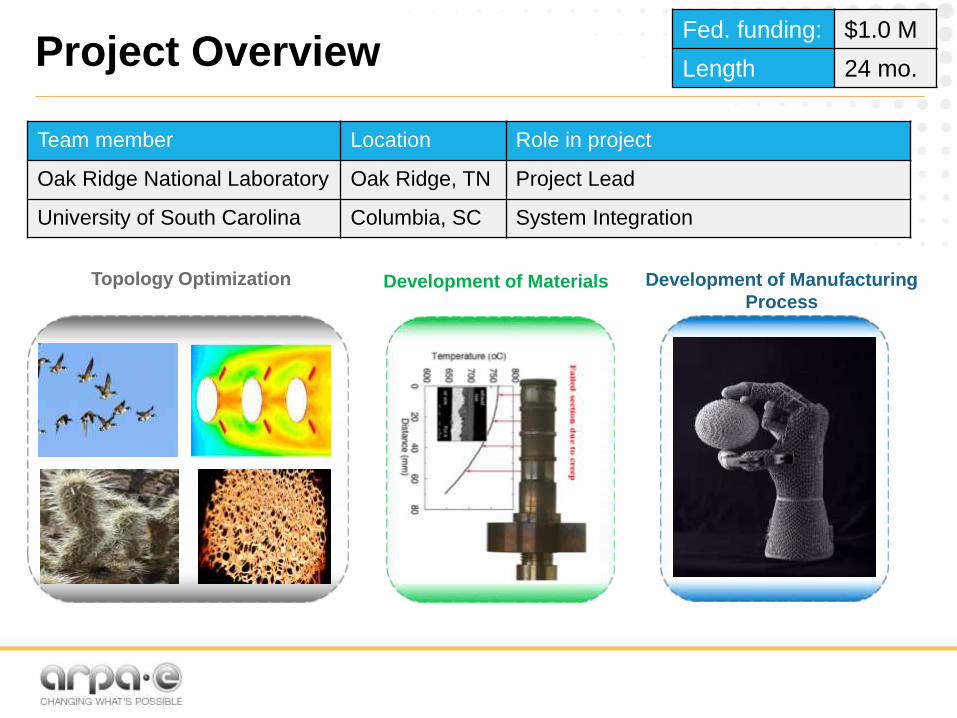
Project OverviewFed. funding: $1.0 M
Length 24 mo.
Team member Location Role in project
Oak Ridge National Laboratory Oak Ridge, TN Project Lead
University of South Carolina Columbia, SC System Integration
Topology Optimization Development of Materials Development of Manufacturing
Process

Solution Strategy
2

Innovation and Objectives
Innovation• High-performance computing:
achieve optimum solution
• Topology optimization: maximize
thermal-hydraulic performance
• Multi-physics modeling: investigate
thermal-mechanical conjugate problem
• Additive manufacturing: complex
geometry and materials
• Advanced visualization: quality
assurance and fracture analysis
Task outline, technical objectives• Design: unprecedented thermal-
hydraulic performance-Target 200%
improvement UA from state-of-the-art.
• Materials: suitable thermal
conductivity and sufficient mechanical
strength at temperatures ~1000°C.
• Manufacturing cost: reduced by at
least 30% compared to the state-of-
the-art technology.
Tech-to-Market objectives
• Engage commercial entities: Isotherm
Inc., Atrex Energy
• SOFC industry will be first target
• Stakeholders from additive
manufacturing industry are onboard

Progress- Value Proposition
𝑄 = ℎ𝐴∆𝑇
Improvement in Heat Transfer Coefficient
Improvement in Heat Transfer Surface Area
Heat transfer
coefficient
Pressure
gradient
• Improved resistance to thermal
fluctuations
• Design of headers is a
challenge
• Modularity is possible
• AM is required to implement
• Design of headers is a challenge
• Modularity is difficult
• AM is required for
implementation
• 2/3-dimensional wavy design a
simplified version
• Modularity is possible
• Commercially available foams
can be deployed
• Conventional manufacturing
process can be used.

Progress- Design Optimization
Rectangular/Hollow/Spiral Q= 5.2 kW ΔPs = 0.39 psi
ΔPt = 18 psi
Rectangular/Hollow Q= 5.95 kW ΔPs= 0.36 psi
ΔPt = 27 psi
Triangular/Hollow Q= 4.66 kW ΔPs= 0.43 psi
ΔPt = 19 psi
Triangular/Hollow/Spiral Q= 6.11 kW ΔPs= 0.29 psi
ΔPt = 35.79 psi
Infiltrated SiC (wall)
[814 K, 1022 K]
Air (tube-side, cold)
T = [673 K, 1016 K]
T_out = [916 K, 930K]
Pin = 11.67 psi
Pout = -24.12 psi
ΔP ~ 35.79 psi
100
97.0499553
98.5014924596.36055092
96.41358202 93.1150472
86.99828785
93.1211079
81.66184336
83.09216806
80
82
84
86
88
90
92
94
96
98
100
0 0.02 0.04 0.06 0.08 0.1 0.12 0.14
% max UA vs. Downstream Distance (m)
√3
2𝑃
√3
2𝑃
√3
2𝑃
√3
2𝑃
𝑃: 𝑃𝑖𝑡𝑐ℎ, 𝑇𝑟𝑖𝑎𝑛𝑔𝑢𝑙𝑎𝑟 ; √3
2𝑃: 𝐿𝑖𝑛𝑒𝑎𝑟 𝐷𝑖𝑠𝑡𝑎𝑛𝑐𝑒
𝑏𝑒𝑡𝑤𝑒𝑒𝑛 𝑇𝑢𝑏𝑒 𝑅𝑜𝑤𝑠

Progress- Thermomechanical Optimization
High Thermal
Stress
High Temperature
• Obtain conjugate heat transfer solution
• Map to thermal expansion simulation
• Quantify structural integrity (stress, displacement thickness)
• Test if displacement thickness is within design limits

7
Progress- Design Optimization

Progress- Manufacturing Process
Sample printing (medium-sized printer, Innovent)
HxN printing (largest printer, M-flex)
Obtaining the best printing parameters for
parts
• For testing post processing
• Prelude into large heat exchanger printing
• Dry time, saturation (or binder amount),
and spread speed

Progress- Manufacturing Process
Heat exchanger printing (large-sized printer, M-flex)
Using small puck and cuboid printing
parameters (on largest printer) is not feasible
• Size of parts and binder choice become
important
• Buckling, warping, and cracking can be
issues
Printing process flow
Sample printing (medium-sized printer, Innovent)
Powder
preparation
Printing
Process
and curing
Depowdering,
Infiltration
/sintering

Progress- Manufacturing Process
‣ Goal: Make hermetically sealed, high SiC content part parts by 3D printing
followed by subsequent infiltration processes
‣ Approach:
– SiC printed pucks by binder jetting
• Reactive infiltration with molten silicon
• infiltration and pyrolysis of polymer precursor for carbon, followed by
reactive infiltration with molten silicon
• infiltration and pyrolysis of polymer precursor for SiC with SiC precursor
PIPs
– SiC sintering with sintering aidAchieved desired permeability
=
Cannot make=
In progress=

Progress- Manufacturing Process
2 hours 4 hours 8 hours
1550 °C DONE
1670 °C DNW DNW DNW
1800 °C DNW DNW DNW
2 hours 4 hours 8 hours
1550 °C
1670 °C DONE DONE DONE
1800 °C DONE DONE DONE
2 hours 4 hours 8 hours
1550 °C
1670 °C DONE
1800 °C DONE DONE
Molten Si Infiltration
1 phenolic PIP
2 phenolic PIP
Processing Temperature (C) Leak Rate (psi/min)
1550 1440
1670 744
1800 0.85
intrinsic to tester 1.12
overinfiltration of Si 1.16
8 hrs, 1 PIP

Progress- Material Characterization
Ln (Strength (MPa))
Strength (MPa)
Pro
ba
bility
of F
ailu
re
4.3
1
Weibull Analysis of Flexural
Strength Results at RT
Flexural Strength
Mechanical Evaluation of Siliconized SiC Composites

Progress- Material Characterization
a 0.27 mm
2c 0.64 mm
Y 1.24
s 162.2 MPa
KIC 3.64 MPa-m0.5
Fractographic Analysis of Test Specimen to Determine Fracture Toughness

Progress- Material Characterization
Determination of Young’s Modulus by Impulse Excitation and Coefficient
of Thermal Expansion by Thermomechanical Analysis

Progress- Materials Characterization
Machine: Metrotom
Resolution: ~20 micron
Isometric viewVideo of scans in z-direction
CT scans of Coil HxN – tool for printing, finding defects

Progress- Materials Characterization
Preliminary assessment of AFA alloy developed at ORNLAlloy composition
Sand mold for casting
Major thermo-physical properties
Variation of mechanical strength with temperature

Progress- Development of cost model
Cost of AFA alloy developed at ORNLComparison of different AM processes
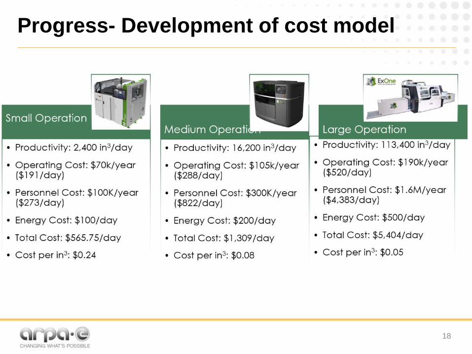
18
Progress- Development of cost model

Market Applications
• Modular power generation/concentrating
solar
• Aerospace- Gas turbine engines/hybrid
electric propulsion
• Nuclear- VHTR/Molten salt reactorso Transformational Challenge Reactor

• Design process, materials selection and
manufacturing process are interdependent.
• High-temperature materials in general have
low thermal conductivity.
• Presence of moisture in working fluids can
cause material degradation.
• 3D printing with ceramic materials is a
nascent area. Process optimization is
needed to achieve topographical features
and hermetically seal.
• A trade-off between design, manufacturing
process and performance is mandatory to
achieve a low-cost device.
• System integration of different hybrid power
systems consisting of the heat exchangers.
Risks