Embed Size (px)
Citation preview

International Post-SMiRT Conference Seminar on Seismic Isolation, Passive Energy Dissipation and Active Control of Seismic Vibrations of Structures
Taormina, Italy, August 25-27, 1997
DEVELOPMENT OF NEW MATERIALS FOR SEISMIC ISOLATION AND PASSIVE ENERGY DISSIPATION - PART I: EXPERIMENTAL TESTS ON NEW
COMPOUND ELASTOMERIC BEARINGS
F. Braga, M. Dolce, A. Ferrigno, M. Laterza, G. Marotta, A. Masi, D. Nigro, F. Ponzo Dipartimento di Strutture, Geotecnica, Geologia applicata all’Ingegneria (DiSGG),
Ateneo della Basilicata, Potenza, Italy ABSTRACT In this paper an outline of a huge test program carried out at the Laboratory of Testing Materials and Structures of the DiSGG of the University of Basilicat, at Potenza, is given. About 500 high damping elastomeric bearings (HDEB) for seismic isolation were tested, and the mechanical and hysteretic characteristics of both new and artificially aged bearings were evaluated. Three different groups (A, B, C) of devices were tested, each group being relevant to a different compound based on a different elastomer (oleifinic, dienic and nitrilic base). For each group of device, 24 different specimen types were tested, whose differences are relevant to dimensions, shape (circular or square), primary and secondary shape factor. These characteristics do not change from one group to another, so that immediate comparisons among the different compounds can be made. In this paper the peculiar characteristics of the three compounds studied, the standards adopted to evaluate the characteristics of the basic materials and the main steps in the execution process of the devices are briefly described, highlighting the importance of the various steps on the quality of the final products. Then, the geometric characteristics of all the bearings are illustrated (dimensions, shape, thickness and number of elastomeric layers, thickness of steel shims, primary and secondary shape factor). Finally, the types of test performed on the specimens as well as the test equipment and set up are described. Particular attention is devoted to the accelerated ageing procedures, used to evaluate the durability of compounds and devices. 1. CHARACTERISTICS OF THE DEVICES The experimental program herein described was designed and carried out for the COSMES Consortium, under the scientific supervision of professors Giangreco and De Luca (University of Naples “Federico II”). It is part of the wider research program named "Products and technologies for the reduction of seismic effects on constructions”, which was financed by the Italian Ministry of the University and of the Scientific and Technological Research (MURST). Its main objective is the setting up and validation of new base isolation devices for the seismic protection of buildings. The mechanical and hysteretic characteristics of new and artificially aged devices under shear and compression actions, both statically and dynamically applied, were evaluated in the tests. All the tests were carried out at the

Laboratory of Testing Materials and Structures of the Department of Structures, Geotechnics and Geology (DiSGG) of the University of Basilicata, at Potenza. HDEB devices, i.e. devices realised with artificial elastomer (synthetic rubber), have been examined, instead of the more usual HDRB, i.e. made of natural rubber. Using artificial elastomers is particularly interesting. While natural rubber has a set of mechanical characteristics pre-defined and substantially not modifiable, once the Shore hardness has been fixed, in the artificial elastomers some characteristics, e.g. the ones which are more significant for the particular use, can be upgraded, thus obtaining the required performances. Obviously other characteristics, which are less important in the specific application, result to be in some extent degraded. The resistance to environmental actions, the durability and the energy dissipation properties were considered the most significant characteristics in the present program. In fact, the three produced elastomers (respectively with oleifinic, dienic, and nitrilic base) achieved better performances, as regards the above reported characteristics, than natural rubber, even if other characteristics, considered less important, were degraded; in particular: • the elastomer of oleifinic base (Terpolymer Ethylene Propylene Diene EPDM) is
characterised by a greater resistance to the aggressive environmental actions and to the ageing;
• the elastomer of dienic base (Polybutadiene) is characterised by a very low vitreous transition temperature, so that it is well suited in particularly severe environmental conditions;
• the elastomer of nitrilic base (Nitrilic Rubber) is characterised by greater dissipative capacities while having a low mechanical resistance.
Adopting the three different elastomers as the basic components of three different compounds, the following three groups (A, B, C) of seismic isolation devices, meant for three different uses, have been realized: • Group A, suitable for aggressive environment and having high durability; • Group B, suitable for low temperature environments; • Group C, suitable for soft soil foundations, having high energy dissipating capacity. 1.1 Characteristics of basic components The peculiar characteristics of the materials used and the relevant standards are reported in Tab.1. To enable some comparisons, the characteristics of a typical natural rubber compound, used for the production of HDRB, is also reported (indicated by Rubber). Moreover, the characteristics of the steels used for the end plates and for the internal shims (with the exception of the B Group specimens n° 3bis and 12bis, whose internal shims are made of composite material) are reported. The above data have been provided by the Elastomers Division of EniChem, that designed and produced the elastomers and the compounds, and by the Antivibration Systems Division of Pirelli, that realised all the devices. Examining closely the characteristics of the different compounds is beyond the purpose of the present paper. However a summary examination of the data in Tab. 1 highlights some indubitable advantages in using a compound based on artificial elastomer, and then the interest of this research. For instance, if a reduction of the tensile and tear strenghts can be accepted, as they are beyond the usual demands to seismic devices, then a significant increase in durability and a significant decrease of the shear modulus, while increasing shear strain, can be obtained (see Group A for shear strain = 200%).

CHARACTERISTICS GROUP A EPDM
GROUP BPolybutadien
GROUP CNitrilic
RUBBER natural
ADOPTED STANDARDS
Vitreous transition temperature
-54 °C -100°C -10°C -70°C DSC scanning 10°C/m
Shore Hardness A 63 62 47 65 ASTM D 2240 Tensile strength 16.6 MPa 16.2 MPa 13.6 MPa 21.1 MPa ASTM D 412
Elongation at break (EB) 620% 580% 760% 550% ASTM D 412 DIE C Elastic yield 33% 32% 12% -------- DIN 53512 A
Compression set 18.2% 28% 38% 28.6% ASTM D 575 A Tear resistance 23.7 N/mm 21.2 N/mm 14.6 N/mm 37.4 N/mm DIN 53507
Curing time 32 min. 9 min. 15 min. -------- ASTM D 2084 T90(160°C)Thermo-oxidative ageing resistance
Hardness var.: +4
Hardness var.: +2
Hardness var.: +6
Hardness var.: +2
ASTM D 573
Ageing resistance 1440 hours 1344 hours 1000 hours 500 hours ASTM D 518 20% All.,40°C, 25pphm O3
Thermal life at 30°C (residual EB = 100%)
51 years 35 years 63 years 39 years ISO/TC 45 N 5846 (Arrhenius Plot)
Elastomer-Steel bond Elast.-Composite bond
21.2 N/mm 18.0 N/mm 14.9 N/mm
14.5 N/mm 18.0 N/mm
ASTM D 429B
Shear modulus 100% shear Strain 200% shear Strain
0.90 MPa 0.35 MPa
0.80 MPa
--------
< 0.48 MPa
--------
0.90 MPa 0.62 MPa
CNR 10018/85
Damping coefficient 0.5Hz, 100% shear strainstatic 100% shear strain
13%
11.9%
12.1% 10.1%
16.5% 14.8%
12%
10.2%
SEAONC 90
STEEL (internal shims) FeP01 FeP01 FeP01 FeP01 UNI 5866 STEEL (end plates) Fe510B Fe510B Fe510B Fe510B UNI 7070
Tab. 1. Chemical, physical and mechanical characteristics of the basic components. 1.2. Manufacturing of the devices The manufacturing process of the devices, identical for the three groups, is constituted by three main phases: mixing, calendering, moulding. The first phase aims at obtaining the compound by mixing the polymer and some additives (carbon black, antioxidants, rubber accelerators, sulphur and other smaller ingredients). The calendering phase aims at obtaining compound sheets of almost uniform thickness (in this case the adopted thickness range from 1 to 4 mm, with tolerances of the order of 0.05 mm). Finally, as a result of the moulding phase, the definitive assembling of the elastomeric layers, of the steel shims and of the end plates is obtained; to such purpose, the sandwich constituted by the bottom and the top end plates, the internal elastomeric layers and steel shims, alternated and with an intermediate adhesive, are arranged in a fit mould. Then the mould is put under a compressing press and led to the temperature of 150÷160°C. This temperature is kept till the vulcanization process of both elastomer and adhesive is completed. It is worthy to note that the actual behavior of a device (stiffness under compression and shear, damping coefficient, durability, resistance to aggressive environment) substantially depend not only on the characteristics of the basic materials (elastomer, steel shims and plates, adhesives) but also on the effectiveness of the manufacturing modalities (mixing, calendering, moulding). Therefore an estimate of the actual behavior of a device is not very significant if obtained by only assessing the characteristics of the basic materials. In fact, the accurateness in carrying out the three main phases of the execution process has a strong influence on the good behaviour of the isolator. Consequently, a reliable evaluation of the

mechanical characteristics of a single isolator ask for tests on the basic materials as well as on the device as a whole. 1.3. Geometric characteristics of the devices The geometric characteristics of all the tested devices are reported in Tab. 2.
N. Group
Shape Dmax D’max n s he s' s" htot Type S1 S2
[mm] [mm] [mm] [mm] [mm] [mm] [mm] 1 A, B, C Ο 75 72 6 2.4 14.4 0.5 25 66.9 e 7.50 5 2 A, B, C Ο 75 72 3 4.8 14.4 0.5 25 65.4 3.75 5 3 A, B, C Ο 75 72 10 2.4 24 0.5 25 78.5 c 7.50 3
3bis B Ο 75 72 10 2.4 24 0.5 25 78.5 c 7.50 3 4 A, B, C Ο 75 72 5 4.8 24 0.5 25 76 d 3.75 3 5 A, B, C 150 144 12 2.4 28.8 1.0 25 89.8 15 5 6 A, B, C 150 144 6 4.8 28.8 1.0 25 83.8 7.50 5 7 A, B, C 150 144 20 2.4 48 1.0 25 117 15 3 8 A, B, C 150 144 10 4.8 48 1.0 25 107 7.50 3 9 A, B, C Ο 150 144 12 2.4 28.8 1.0 25 89.8 15 5 10 A, B, C Ο 150 144 6 4.8 28.8 1.0 25 83.8 e 7.50 5 11 A, B, C Ο 150 144 20 2.4 48 1.0 25 117 b 15 3 12 A, B, C Ο 150 144 10 4.8 48 1.0 25 107 c 7.50 3
12bis B Ο 150 144 10 4.8 48 1.0 25 107 c 7.50 3 13 A, B, C Ο 150 144 40 2.4 96 1.0 25 185 15 1.5 14 A, B, C Ο 300 288 12 2.4 28.8 2.0 25 100.8 30 10 15 A, B, C Ο 300 288 6 4.8 28.8 2.0 25 88.8 15 10 16 A, B, C Ο 300 288 40 2.4 96 2.0 25 224 a 30 3 17 A, B, C Ο 300 288 20 4.8 96 2.0 25 184 b 15 3 18 A, B, C Ο 400 384 40 3.2 128 3.0 25 295 a 30 3 19 A, B, C Ο 400 384 20 6.4 128 3.0 25 235 b 15 3 20 A, B, C Ο 400 384 10 12.8 128 3.0 25 205 c 7.50 3 21 A, B, C Ο 400 384 5 25.6 128 3.0 25 190 d 3.75 3 22 A, B, C Ο 400 384 20 3.2 64 3.0 25 171 30 6
Tab. 2. Geometric characteristics of all the specimens. The symbols used in the table have the followings meanings: N. = identification number (from 1 to 22 + 3bis and 12bis) of the 24 different bearings; Group = group which the device belongs (A, B, C); Shape = shape of the device (O circular, square); Dmax = max dimension of the device (Diameter for circular devices, Side for square devices); D’max = max dimension of the internal steel shims and of the end plates; n = number of elastomeric layers; s = thickness of elastomeric layers; he = total elastomeric height (he = n x s); s' = thickness of steel shims; s" = thickness of end plates; htot = total bearing height (htot = he + (n-1) x s’ + 2 x s’’); Type = type of bearing (a, b, c, d, e, f); S1 = primary shape factor (S1 = D’max/4s); S2 = secondary shape factor (S2 = D’max/ he).

Some preliminary considerations have to be made in order to understand the criteria adopted in defining the dimensions of the specimens reported in Tab. 2. As already said, a reliable evaluation of the mechanical characteristics of single isolators ask for tests on the basic materials as well as on devices as a whole. However, real devices, besides being very expensive, often have so large sizes that it is difficult to find Laboratories which are able to test them and obtain a reliable evaluation of the main mechanical characteristics. It is then clear how important it is to be able to perform tests on reduced scale specimens identical to the real ones (on the basis of materials, dimensional ratios, shape factors, execution process), knowing the extent of the differences, if any, to be expected in the experimental response between the reduced and the full scale specimens. At this purpose, in selecting the dimensional ratios of the specimens, the starting point was the design of the bearings with the maximum values of Dmax , to be considered as full scale devices; the dimensions of the reduced scale devices have been defined in such a way that they are models of the real ones in a suitably reduced scale. Circular bearings with diameter Dmax = 400 mm and total elastomer height he = 128 mm, have been choosen as full scale devices. To the purpose of examining the influence of the primary shape factor S1 on the mechanical characteristics, four different specimens have been defined. These specimens have the same he = 128 mm, but different primary shape factor. Once a basic value of S1 = 3.75 was selected, the other values ensued: 3.75 (N.= 21), 7.5= 3.75 x 2 (N.= 20), 15= 3.75 x 4 (N.= 19), 30= 3.75 x 8 (N.= 18). The change of S1 , while keeping he constant, was obtained by varying the thickness s of the individual layers of elastomer and then the number of elastomeric layers n; four values of n (each one multiple of a basic value equal to 5) were selected, respectively equal to 5, 10, 20 and 40. The only exception to this plan is the bearing N. 22, having total elastomeric height he = 64 mm, i.e. half the height of the other ones, and S1 = 30. A bearing with such an unusual dimensions has been considered to understand the role of the total elastomeric height, when S1 is kept constant. Once the dimensions of the full scale devices were defined, other 17 different reduced scale devices were designed. They are divided into 4 categories, which are characterised by 3 different loading areas and 1 shape variation. The 3 categories with circular shape have Dmax respectively equal to 75 mm, 150 mm and 300 mm, while the category with square shape has Dmax = 150 mm. By examining the data in Tab. 2, relevant to the circular bearings, it appears clear that most of the bearings of the three small scale categories (Dmax = 75 mm, 150 mm, 300 mm) represents reduced-scale models of a full scale bearing, having the same S1 and S2 and smaller Dmax. This is true as long as the behavior of the bearings is substantially not affected by the thickness of the steel parts, as it is for the currently used thickness values. In particular, the last but two column (Type) of table 2 highlights the direct correspondences, thus identifying 5 types, each one marked by a lowercase letter (a, b, c, d, e). It has to be noted that all the bearings belonging to the same type are similar but differently scaled. It was not possible to establish the above described correspondence for all the bearings, particularly, for bearings N. 2, 9, 13, 14, 15, 22. They are however useful to evaluate the influence of the primary and secondary shape factors, whose values are differently combined. Finally the square-shaped specimens N. 5, 6, 7, 8 have shape factors identical to the circular-shaped specimens N. 9, 10, 11, 12 respectively, thus permitting a direct comparison to study the influence of the shape.
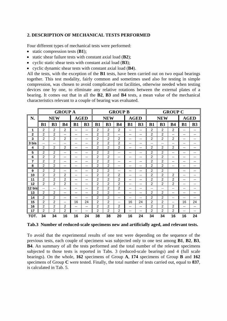
2. DESCRIPTION OF MECHANICAL TESTS PERFORMED Four different types of mechanical tests were performed: • static compression tests (B1); • static shear failure tests with constant axial load (B2); • cyclic static shear tests with constant axial load (B3); • cyclic dynamic shear tests with constant axial load (B4). All the tests, with the exception of the B1 tests, have been carried out on two equal bearings together. This test modality, fairly common and sometimes used also for testing in simple compression, was chosen to avoid complicated test facilities, otherwise needed when testing devices one by one, to eliminate any relative rotations between the external plates of a bearing. It comes out that in all the B2, B3 and B4 tests, a mean value of the mechanical characteristics relevant to a couple of bearing was evaluated.
GROUP A GROUP B GROUP C N. NEW AGED NEW AGED NEW AGED B1 B3 B4 B1 B3 B1 B3 B4 B1 B3 B1 B3 B4 B1 B3 1 2 2 2 -- -- 2 2 2 -- -- 2 2 2 -- -- 2 2 2 -- -- -- 2 2 -- -- -- 2 2 -- -- -- 3 2 2 2 -- -- 2 2 2 -- -- 2 2 2 -- --
3 bis -- -- -- -- -- 2 2 2 -- -- -- -- -- -- -- 4 2 2 2 -- -- 2 2 2 -- -- 2 2 2 -- -- 5 2 2 -- -- -- 2 2 -- -- -- 2 2 -- -- -- 6 2 2 -- -- -- 2 2 -- -- -- 2 2 -- -- -- 7 2 2 -- -- -- 2 2 -- -- -- 2 2 -- -- -- 8 2 2 -- -- -- 2 2 -- -- -- 2 2 -- -- -- 9 2 2 -- -- -- 2 2 -- -- -- 2 2 -- --
10 2 2 2 -- -- 2 2 2 -- -- 2 2 2 -- -- 11 2 2 2 -- -- 2 2 2 -- -- 2 2 2 -- -- 12 2 2 2 -- -- 2 2 2 -- -- 2 2 2 -- --
12 bis -- -- -- -- -- 2 2 2 -- -- -- -- -- -- -- 13 2 2 -- -- -- 2 2 -- -- -- 2 2 -- -- -- 14 2 2 -- -- -- 2 2 -- -- -- 2 2 -- -- -- 15 2 2 -- 16 24 2 2 -- 16 24 2 2 -- 16 24 16 2 2 2 -- -- 2 2 2 -- -- 2 2 2 -- -- 17 2 2 2 -- -- 2 2 2 -- -- 2 2 2 -- --
TOT. 34 34 16 16 24 38 38 20 16 24 34 34 16 16 24
Tab.3 Number of reduced-scale specimens new and artificially aged, and relevant tests. To avoid that the experimental results of one test were depending on the sequence of the previous tests, each couple of specimens was subjected only to one test among B1, B2, B3, B4. An summary of all the tests performed and the total number of the relevant specimens subjected to those tests is reported in Tabs. 3 (reduced-scale bearings) and 4 (full scale bearings). On the whole, 162 specimens of Group A, 174 specimens of Group B and 162 specimens of Group C were tested. Finally, the total number of tests carried out, equal to 837, is calculated in Tab. 5.

N. GROUP A GROUP B GROUP C B1 B2 B3 B4 B1 B2 B3 B4 B1 B2 B3 B4
18 2 2 2 2 2 2 2 2 2 2 2 2 19 2 2 2 2 2 2 2 2 2 2 2 2 20 2 2 2 2 2 2 2 2 2 2 2 2 21 2 2 2 2 2 2 2 2 2 2 2 2 22 2 2 2 -- 2 2 2 -- 2 2 2 --
TOT. 10 10 10 8 10 10 10 8 10 10 10 8 Tab.4 Number of new and artificially aged full scale specimens, and relevant tests.
GROUP A GROUP B GROUP C Reduced-scale Full scale Reduced-scale Full scale Reduced-scale Full scale
B1 34 + 2x16 = 66 2 x 10 = 20 38 + 2x16 = 70 2 x 10 = 20 34 + 2x16 = 66 2 x 10 = 20 B2 -- 5 -- 5 -- 5 B3 3x17 + 2x2x12 = 99 3 x 5 = 15 3x19 + 2x2x12 =
105 3 x 5 = 15 3x17 + 2x2x12 = 99 3 x 5 = 15
B4 2x2 x 8 = 32 3x3 x 4 = 36 2x2 x 10 = 40 3x3 x 4 = 36 2x2 x 8 = 32 3x3 x 4 = 36TOT 197 76 215 76 197 76
Tab. 5 Total number of tests performed. As shown in Tables 3 and 4, the tests were performed both on new and artificially aged bearings. The specimens to be aged were tested before and after the artificial ageing. Low levels of load, which were taken equal to the design ones, were applied, so that no degradation could occur during testing and the effects of the ageing could be correctly evaluated. All the tests have been conducted by controlling displacements, with a mean sampling frequency of about 100 points (applied displacements and relevant loads) per cycle, to have a detailed description of the behavior of the devices, and evaluate suitably their mechanical and hysteretic characteristics. 2.1. Static compression tests (B1 tests) Both reduced-scale bearings (N. 1-17 with Dmax = 75 mm, 150 mm, 300 mm) and full scale bearings (N. 18-22 with Dmax = 400 mm) were subjected to B1 tests. The tests were conducted in a static way, by applying a monotonically increasing compression load and measuring the relevant displacements. A maximum compression stress equal to 21 MPa was applied on all the specimens, corresponding to three times the design stress (7 MPa). However, for the above stated reasons, the specimens to be subjected to accelerated ageing were loaded with a maximum compression stress equal to 7 MPa. Creep tests were also carried out on all the full scale specimens, by applying the design load for 24 hours and measuring the displacement increases. 2.2 Static and dynamic shear tests with constant axial load (B2, B3, B4 tests) The shear tests with constant axial load were performed in three different static and dynamic modes. In particular, the axial load was always applied statically, whereas the shear deformations were applied both statically (frequency < 0.05 Hz) and dynamically (frequency > 0.05 Hz). In the latter case the test frequencies have been selected in the typical working field of the base isolation devices under seismic action (0.2-0.6 Hz).

The three different types of test were always performed by controlling displacements, as described below. • Static shear failure tests with constant axial load (B2 tests)
These tests were performed only on real scale specimens not subjected to accelerated ageing, by applying a constant axial load giving the design stress (7 MPa) together with a monotonically increasing shear strain up to failure or at least 300% (maximum applied displacement > 384mm for the bearings N. 18-21).
• Cyclic static shear tests with constant axial load (B3 tests) These tests were performed both on reduced-scale and on full-scale specimens, by applying a constant axial load giving 50%, 100% and 150% the design stress (7 MPa) together with a sinusoidal shear strain varying according to the following sequence of maximum strain: ±10%, ±30%, ±50%, ±75%, ±100%, ±150%. The sequence included 10 and 5 consecutive cycles at each strain level, on the full and the reduced scale bearings respectively. The full scale bearings were subjected to a larger number of cycles, in order to detect any possible degradation effect. As regards the specimens subjected to artificial ageing, a constant axial load giving 50%, and 100% the design stress (7 MPa) together with a sinusoidal shear strain varying according the following sequence of maximum strain: ±10%, ±30%, ±50%, ±75%, ±100% were applied. The sequence included 5 consecutive cycles at each strain level.
• Cyclic dynamic shear tests with constant axial load (B4 tests) These tests were performed both on reduced-scale and on full-scale specimens, by applying a constant axial load resulting in 50%, 100% and 150% the design stress (7 MPa) on the full scale specimens, while on the reduced-scale specimens only two levels of axial load were applied (100% and 150%). Together with the axial load, a sinusoidal shear strain was applied according to the following sequence of maximum strain: ±10%, ±30%, ±50%, ±75%, ±100%. The sequence included 10 and 5 consecutive cycles at each strain level, on the full and the reduced scale bearings respectively. The shear strains were applied dynamically at the following frequencies: 0.2 Hz, 0.4 Hz and 0.6 Hz on the full-scale bearings, 0.4 Hz and 0.6 Hz on the reduced-scale bearings.
3. ACCELERATED AGEING Reference to specimens, particularly bearing N. 15, to be subjected to accelerated ageing was frequently made in the previous section. At this regard, some preliminary considerations have to be stated to clarify what is meant by accelerated ageing and the reasons of its execution. It is common knowledge that the characteristics of polymers (synthetic and natural rubbers) are time-dependent; thus, it is necessary to evaluate the relevant changes in the behaviour of elastomeric bearings. This evaluation presents the same difficulty already illustrated when dealing with the evaluation of the mechanical properties, i.e. the difficulty to extrapolate the results of tests made on basic material, specifically on compounds, to devices. Moreover, suitable test procedures have not been set up yet, ageing being a very complex phenomenon. As a consequence, a reasonable prediction of the variations of the mechanical properties of an isolator in the long run is an open question so far, as the technical literature on the argument clearly shows (as an example see Barker, 1991 and Fuller, 1995). In order to give a contribution to the resolution of the problem, some isolators have been subjected to a process of accelerated ageing, in accordance with the ISO/TC 45 N 5846. The aim of the test is to estimate the useful lifetime of elastomeric bearings, i.e. the time interval

during which the device keeps its characteristics fit to use at the service temperature. Since the laboratory tests have to be performed within a reasonable time interval, the ISO standard suggests the use of the Arrhenius law. This law, according to the development of the chemical reactions in organic compounds, establishes a direct proportionality between the logarithm of the time t expressed in days (ln t) and the inverse of the absolute temperature expressed in Kelvin degrees (1/T), resulting in the following equation
ln t = (E/R) x (1/T) + B where E is the activation energy of the ageing reaction, R is the gas constant or the Boltzmann constant (depending on the units) and B is an integration constant. The representation of ln t versus 1/T is better known as Arrhenius plot and it coincides with a straight line, under the hypothesis, to be confirmed, that the E/R ratio is constant,. As the standard ISO/TC 45 N 5846 requires, the variations of one or more selected properties must be determined as a function of time, for some prefixed values of temperature. In this case, 3 values of temperature and 2 mechanical properties, namely the axial and shear stiffnesses of the isolators, were considered. Theoretically, the duration of the test should be as long as the selected properties achieve a prefixed threshold value, chosen to suit the conditions of use. Actually, as the application of the above described procedure would be very expensive, due to its duration, the variations of properties are typically evaluated after a prefixed interval of time, generally rather limited (from 1 to 3 weeks). By suitably extrapolating the results, the time in which the selected properties would achieve the prefixed threshold value is estimated. This simplified approach has the advantage of being not much expensive, but it frequently asks for strong extrapolations that are applied to variation laws, which result to be significantly non linear. Consequently, inaccurate and maybe optimistic estimations of the ageing time could be obtained, whose errors increase as the ratio between the adopted test duration and the necessary time to achieve the threshold value decreases. However, as the simplified approach is usual in the current practice and, moreover, it was also used to estimate the behaviour of the aged compound, it seemed appropriate also for the prediction of the lifetime of the devices. In order to make a better extrapolation of the results, a test duration ranging from 4 weeks up to a maximum time of 18 weeks was used in the present experimental program. In Table 6 the complete program of accelerated ageing performed on the bearing N. 15 is shortly summarized. Tests B1 and B3 have been performed before and after the ageing, and the behavior of the specimens has been evaluated and compared in terms of axial and shear stiffness.
GROUP A (Bearing N. 15) GROUPS B-C (Bearing N. 15) TES
T Specimens
number Temperature
(°C) TIMES (weeks)
Specimens number
Temperature (°C)
TIMES (weeks)
6 100 4-8-12-14-16-18 6 80 4-8-12-14-16-18B1 6 80 4-8-12-14-16-18 6 70 4-8-12-14-16-18
4 60 4-8-12-16 4 60 4-8-12-16 8 100 8-12-14-16 8 80 8-12-14-16
B3 8 80 4-8-12-16 8 70 4-8-12-16 8 60 4-8-12-16 8 60 4-8-12-16
Tab.6. Accelerated ageing program performed on the bearing N. 15.

4. TEST FACILITIES 4.1 Test Apparatus The experimental program was carried out using three different test facilities.
For the static compression tests (Tests B1) a press with the maximum capacity of 3000 kN was used (Figs.1 and 2). The loads applied by this press were measured by precalibrated load cells, whose capacities vary betwwen 100 kN and 4000 kN, according to the maximum load applied during test. The displacements were measured by inductive linear transducers linked to the anchorage plates of the isolators. The transducers were arranged to evaluate also possible rotations of the top plate of the isolator (Fig. 3). For the cyclic static (Tests B3) and dynamic (Tests B4) shear tests, both performed by keeping the axial load constant, the test apparatus was able to apply simultaneously compression (in the horizontal direction) and shear (in the vertical direction) to a couple of identical test specimens. Figs. 4 and 5 show, respectively, a detailed layout and an overall view of the test apparatus, while Fig. 6 shows a detail during a shear dynamic test.
Fig. 1 Static compression test rig.
Fig. 2 Particular of a static compression test.
LinearTrasducer
Load Cell
Hydraulic Press
Device
Fig. 3 Compression test instrumentation.

2900
L=12152 UPN 240
L=600HEA 300
L=1300HEA 320
6 CBLES ø 22
L=1046HEA 300HEA 300
L=2900
HEA 300L=750
HEA 300L=750
L=14002 HEA 300
L=1046HEA 300
HEA 300L=600
L=30354 UPN 200
HEA 300L=600
HEA 300L=600
4 UPN 200L=3035
HEA 300L=600
3065
L=68
0H
EA
180
UPN 240L=860
HE
A 1
80L=
680
L=8702 UPN 80
L=8702 UPN 80
L=68
0H
EA
180
HE
A 1
80L=
680
L=68
0H
EA
180
2100
AC
TUA
TOR
LOA
DC
ELL
HORIZONTALJACK
LOAD CELL ISOLATORS ANDANCHOR BLOCKS
Fig. 4 Layout of double bearing dynamic test machine.

Fig. 5 Double bearing dynamic test machine.
The test machine is made up by a steel reaction frame, whose main elements are a base beam and three stiff columns. Two of them are linked to the base by a double pendulum constraint and one by a hinge. The characteristics of the structure guarantee the complanarity of the bases of the specimens during the application of the loads and allows to follow passively, thanks to a system of cylindrical hinges, the axial displacements of the devices caused by the axial load and by the second order effects caused by the shear deformation. The shear load is applied by a SCHENK hydraulic actuator, which is vertically mounted and linked to the adjacent faces of the two specimens through a loading plate. The compression load is applied and kept constant during test by a ENERPAC double effect jack, which is horizontally mounted between the hinged and the adjacent columns. In order to make it possible the positioning of all the types of isolators to be tested, having different total heights, a series of special rigid connecting pieces were manufactured, to be placed between the columns and the end plates of the isolators.

The SCHENK actuator can develop 200 kN maximum dynamic force and ±125mm maximum displacement. The the maximum static force is equal to 250 kN. The force of the actuator was measured by a pre-calibrated load cell of 250 kN, mounted between the head of the cylinder and the shear loading plate. The actuator is fed by a hydraulic power pack, made up of two pumps, each one having a maximum delivery of 80 litres/min, and by two 63 litres/min servo-valves. Control of the hydraulic system is performed by an electronic controller. The displacements of the actuator are measured and controlled by an internal transducer, while the shear displacements of the specimens were measured by linear transducers connected to the shear loading plate. The axial displacements of
the specimens were measured by two linear spring transducers, positioned between the end plates of the two specimens, in such a way that also possible rotations out of the shear loading plane could be evaluated. An overall layout with the arrangement of the measuring devices is
shown in Fig. 5. A series of ENERPAC double effect jacks, able to develop with sufficient accuracy loads ranging from 30 kN to 3000 kN according to the size of the specimen, were used to apply axial forces. Pre-calibrated load cells of different capacity were mounted between the horizontal jack and the central column of the reaction frame, through a ball joint that guarantees a perfect load centering. The hydraulic power pack feeding the axial load jack, managed by an electronic controller, is composed by a pump, whose maximum delivery is 5 litres/min, and by a system of electrovalves suitably designed. All the static shear failure tests (Tests B2) were carried out with the test rig shown in Figs. 8 and 9, where two or four identical bearings can be
simultaneously tested under static or cyclic shear forces together with a constant axial load. The test machine is made up of a steel reaction structure, whose main elements are a “I” shaped base beam, a horizontal stiff beam and two portal frames that react the axial loads. The structure, thanks to its rigidity, guarantees the complanarity of the end plates of the specimens during test. It also follows passively the axial displacements of the devices caused by the axial load and by the second order effects due to the shear load, thanks to the horizontal stiff beam put between the specimens and the vertical jacks. The shear load is applied by two synchronised ENERPAC double effect jacks, horizontally mounted and linked, through two loading plates, to the adjacent faces of the specimens. The compression load, which is kept constant during test, is applied by two ENERPAC double effect jacks, vertically mounted between the two portal frames and the horizontal stiff beam. The hydraulic system used to feed the axial load jacks in the double-bearing test machine, during the B3 and B4 tests was also used to feed all the jacks.
Fig. 6 Double bearing dynamic test
machine during a shear dynamic test.
Linear Trasducer
Linear Trasducer
Device
Fig. 7 Instrumentation of the double
bearing dynamic test machine.

300
HEB 600
300
2500
SAFETY BLOCK
255
ISOLATORS
PLATE 400x300x50
LOAD CELL 255
HEB 600
24 M20
HORIZONTAL JACK
L=22
10 m
mH
EA
300
TEFLON + INOX
24 M20
HEA 100 HEA 100
ISOLATORS
L=22
10 m
mH
EA
300
3128
3590
VERTICAL JACKVERTICAL JACK VERTICAL JACK
Fig. 8 Layout of the four-bearings test machine.

Fig. 9 Four-bearings test machine.
The maximum vertical capacity of the equipment is 4000 kN. 750 kN maximum horizontal load in compression and 350 kN in tension are the capacity of the two ENERPAC horizontal jacks, for a maximum 900 mm stroke. When testing four specimens the maximum shear displacements was then ±450 mm for each couple. All the loads were measured by pre-calibrated load cells. The presence of suitable slide-ways do not allow displacements of the specimens in direction other than the shear force direction, so that the horizontal displacements of each couple of specimens could be measured by only one inductive transducer. The axial displacements was measured by a couple of inductive transducer for each couple of isolators.

Fig. 10 Particular of a shear failure test.
4.2. Data Acquisition and Analysis System The data acquisition and analysis system was managed by computer, through a managerial software which is able to process and display the experimental results coming from a HBM DMC 9012A signal filter, in real time. The acquired results were filtered and amplified by the HBM filter and converted from analog signals to 16 bit digital signals, with a maximum sampling frequency per channel equal to 9600 Hz. During the dynamic tests the acquisition frequency per channel ranges from (20 to 60 Hz), according to the type of test and the load frequency. The system is able to simultaneously manage up to 72 canals. However, during the tests, at most 8 channels were used to directly acquire the signals and a few other channels were used to simultaneously process data. REFERENCES Barker, L. R., 1991, ”Accelerated long-term ageing of natural rubber vulcanizates. Part 2: Results from ageing tests at 40°C” , Rubber Developments, vol. 44, no 2/3. Fuller, K. N. G., Pond, T. J., 1995, “The long term performance of high damping natural rubber seismic bearings”, European Seismic Design Practice, Balkema, Rotterdam.


![SEISMIC ROOF ISOLATION OF HALKAPINAR … · most efficient seismic isolation solution for the Halkapınar Gymnasium. In this thesis, theory of seismic isolation, ... [18] (From AASHTO](https://img.pdfslide.us/doc/110x75/5b5ba6ce7f8b9a905c8e7903/seismic-roof-isolation-of-halkapinar-most-efficient-seismic-isolation-solution.jpg)