Embed Size (px)
Citation preview

AAllmmaa MMaatteerr SSttuuddiioorruumm –– UUnniivveerrssiittàà ddii BBoollooggnnaa
DOTTORATO DI RICERCA IN
BIOINGEGNERIA
Ciclo XXVIII
Settore Scientifico disciplinare: ING-IND/34
DDeevveellooppmmeenntt ooff nneeww bbiiooaaccttiivvee aanndd ppoorroouuss aappaattiittiicc
ssccaaffffoollddss ffoorr tthhee rreeggeenneerraattiioonn ooff llooaadd--bbeeaarriinngg bboonneess
A dissertation by
Massimiliano Dapporto Ph.D. candidate
Supervisor Co-supervisors Prof. Luca Cristofolini Dott. Simone Sprio
Dott.ssa Anna Tampieri
PhD Coordinator Prof. Elisa Magosso
Esame finale Anno 2016


3
CONTENTS SUMMARY ............................................................................................................ 7
CHAPTER 1 INTRODUCTION ............................................................................... 11
1.1 The Human Skeleton ................................................................................................ 11
1.2 The Bone Structure ................................................................................................... 13
1.2.1 Bone Tissue ........................................................................................................ 13
1.2.2 Bone Cells ............................................................................................................ 16
1.2.3 Bone Modeling and Remodeling ................................................................ 18
1.3 Bone Tissue Engineering and calcium orthophosphates ........................... 20
1.3.1 Cranial injuries and cranioplasty ............................................................... 23
1.3.1.1 Anatomy of the skull .............................................................................. 24
1.3.1.2 Cranioplasty............................................................................................... 25
1.3.1.3 Porous bioceramic scaffolds ............................................................... 27
1.3.1.4 Hydroxyapatite ......................................................................................... 30
1.3.2 Spinal injuries and vertebroplasty ............................................................ 32
1.3.2.1 Anatomy of the spine ............................................................................. 32
1.3.2.2 Osteoporosis and vertebroplasty ...................................................... 34
1.3.2.3 Bone cements ............................................................................................ 36
1.3.2.4 Tricalcium phosphate (TCP) ............................................................... 39
1.4 References .................................................................................................................... 40
CHAPTER 2 OVERVIEW OF METHODS ................................................................. 45
2.1 X-Ray Diffraction (XRD) .......................................................................................... 45

4
2.2 Scanning Electron Microscopy (SEM) ............................................................... 50
2.3 Inductively Coupled Plasma Optical Emission Spectroscopy .................. 53
2.4 Specific Surface Area ................................................................................................ 54
2.5 Particle Size Distribution........................................................................................ 56
2.6 Rheology of suspensions ........................................................................................ 58
2.7 Thermogravimetric analysis (TGA) ................................................................... 60
2.8 Zeta Potential .............................................................................................................. 61
2.9 Mercury porosimetry ............................................................................................... 62
2.10 Mechanical characterization .............................................................................. 63
2.10.1 Compression .................................................................................................... 63
2.10.2 Flexure (4-point bending) .......................................................................... 64
2.11 Design of Experiments .......................................................................................... 65
2.12 References ................................................................................................................. 69
CHAPTER 3 MACROPOROUS APATITE-BASED SCAFFOLDS .................................... 71
3.1 Preparation of macroporous bioceramic scaffolds ...................................... 71
3.1.1 Replica Method ................................................................................................. 71
3.1.2 Direct Foaming Method ................................................................................. 73
3.2 Results and Discussion ............................................................................................ 74
3.2.1 Replica method: role of sponge and thermal treatment ................... 74
3.2.2 A novel Direct Foaming route ..................................................................... 76
3.3 Conclusions .................................................................................................................. 83
3.4 References .................................................................................................................... 84
CHAPTER 4 PREPARATION OF β-TCP SCAFFOLDS BY ROBOCASTING ................... 87
4.1 The robocasting as additive manufacturing approach ............................... 87

5
4.2 Preparation of calcium phosphate pastes for robocasting ....................... 89
4.3 Results and Discussion ............................................................................................ 92
4.4 Conclusions ............................................................................................................... 102
4.5 References ................................................................................................................. 103
CHAPTER 5 DEVELOPMENT OF APATITIC BONE CEMENTS ............................... 105
5.1 Preparation of Sr-doped Calcium Phosphate bone cements (CPCs) .. 105
5.1.1 Synthesis and characterization of Sr-αTCP phases .......................... 106
5.1.2 Synthesis of aqueous setting solutions ................................................. 108
5.1.3 Liquid-On-Powder Ratio And Mixing Procedure .............................. 108
5.2 Results and Discussion ......................................................................................... 110
5.2.1 Characterization of the Sr-doped CPCs ................................................. 110
5.2.2 Designing the performance of CPCs ....................................................... 122
5.3 Conclusions ............................................................................................................... 126
5.4 References ................................................................................................................. 127
FINAL CONCLUSIONS AND FUTURE PERSPECTIVES ........................................... 131
ACKNOWLEDGMENTS ...................................................................................... 133

6

7
The research activity described in the present thesis is devoted to the design and
development of porous bioactive ceramic materials and scaffolds addressed to the
regeneration of bone tissue and was mainly carried out at the Institute of Science
and Technology for Ceramics, belonging to the National Research Council of Italy
(ISTEC-CNR), during my Ph.D. in Bioengineering.
In the last decades the development of porous bioactive scaffolds for bone tissue
engineering has become a major area of material science and biomedical research,
including interdisciplinary approaches spanning from the field of chemistry,
engineering, medicine and biology.
Nowadays there is still a lack of effective therapies able to regenerate large bone
defects, so that the development of implantable bioactive materials able to
overcome the drawbacks related to the use of bone autografts and allografts is
highly demanded. In fact, the currently used bio-inert devices (e.g. metallic
devices) can merely provide a mechanical support without regenerating the
damaged bone tissue often inducing adverse side effects while forcing the patient
to frequent revision surgeries, with also relevant socio-economic impact.
In this respect, the synthesis of artificial bioactive scaffolds able to mimic the
compositional, morphological and mechanical features of bone is considered as the
elective approach for effective tissue regeneration.
The main aim of my work was the design and optimization of forming processes to
produce bioactive ceramics implants as potential solution for the treatment of
large and load-bearing bone defects, particularly in the field of cranio-maxillofacial,
orthopaedic and spinal surgery.
The main inorganic component of bone tissue is a calcium phosphate phase, with
the structure of hydroxyapatite, Ca10(PO4)6(OH)2.
SUMMARY

8
Therefore, the elective materials to provide bone-mimicking scaffolds are calcium
phosphates, mainly hydroxyapatite and tricalcium phosphates.
The processing of these materials into 3-dimensional biomimetic structures with
controlled porosity and adequate structural properties, would favour new bone
formation, penetration and integration with the scaffold.
Clinical application of synthetic materials is mainly hampered by the difficulty in
achieving adequate reproducibility of the scaffold final performance, particularly if
the treatment of large bone defects is demanded. Moreover, the size and shape of
scaffolds for bone reconstruction should face specific anatomical requirements, so
that flexible fabrication technologies are requested to tailor the chemistry and
archictecture of the porous scaffolds in respect to specific applications in bone
surgery.
After a general introduction of bone tissue physiology and an overview on the
analytical methods involved in the research (Chapter I and Chapter II,
respectively), this thesis focuses on the preparation of macro-porous apatitic
structures via a novel route based on the direct foaming of ceramic suspensions
with high-energy planetary ball milling (Chapter III). This method, here used for
the first time in the production of foamed ceramic suspensions, enabled a radical
optimization of the production process significantly improving the final
mechanical properties, thus opening to the development of large and complex-
shape porous scaffolds. Then, Chapter IV describes the preparation of robocasted
3-D macroporous scaffolds for applications in orthopaedics, performed during my
6-months stage at Imperial College London. In this respect, an extensive
optimization of the rheology of colloidal inks based on bioactive β-tricalcium
phosphate was carried out, pointing out a reliable formulation to obtain scaffolds
with controlled architecture by the layer-by-layer deposition of ceramic material.
Finally, Chapter V describes the synthesis and optimization of a novel bioactive
calcium phosphate bone cement based on strontium-substituted apatite, here
proposed for the first time in a formulation enriched with bio-erodible alginate, to
improve cohesion and osteoconductivity. The optimization process enabled the

9
synthesis of fully injectable pastes, exhibiting also improved biologic performance,
if compared with a commercial calcium phosphate cement.
In the present thesis, the optimization of the various parameters significantly
affecting the final properties of the described biomaterials was performed
according to a Design of Experiment approach (DoE). In this way, the parameters
were varied following rational combinations, leading to time and resources saving,
while obtaining preliminary modeling equations of the processes.

10
11
1.1 The Human Skeleton
Sitting, standing, walking and taking a breath are examples for daily acts involving
our skeleton. Without a skeletal system, there would be no rigid framework to
support the soft tissues of the body and no system of joints and levers to allow the
body to move (Fig.1.1).
Fig. 1.1 – The human skeleton (www.clipartof.com)
The human skeleton is composed of 270 bones at birth, which decreases to 206
bones by adulthood after some bones have fused together.
Although the skeleton is usually thought of as only the rigid framework of the
body, the bones provide: 1) structural support for the body, allowing movement
and locomotion by providing levers for the muscles, 2) protection for vital internal
organs from damage, 3) maintenance of mineral homeostasis and acid-base
Chapter 1 INTRODUCTION

Chapter 1
12
balance, 4) reservoirs of growth factors and cytokines and 5) the environment for
hematopoiesis within the marrow spaces [1].
The bones can be classified according to the region of the skeleton they belong to,
or their general shape.
In the former case, the skeleton has been divided into two different regions: the
axial skeleton, including the skull, the vertebral column and the rib cage, and the
appendicular skeleton, which consists of the arms, pectoral girdles, legs and pelvic
girdle.
In the latter case, long bones, short bones, flat bones, and irregular bones have
been classified. Long bones include the femur, humeri, clavicles, radii, ulnae,
metacarpals, tibiae, fibulae, metatarsals, and phalanges. Short bones include the
carpal and tarsal bones, patellae, and sesamoid bones. Flat bones include the skull,
mandible, scapulae, sternum, and ribs. Irregular bones include the vertebrae,
sacrum, coccyx, and hyoid bone.
The typical macrostructure of bones is reported in Fig.1.2 and Fig.1.3, where a long
bone has been chosen as a useful model. Each long bone consists of a central shaft,
the diaphysis, and two ends, the so-called epiphysis. A thin layer of articular
cartilage covers the epiphyses where the bone articulates with other bones
(joints).
Fig.1.2 – Structure of a long bone - Young long bone (the femur) showing the epiphysis,
epiphyseal plates, and diaphysis (a), adult long bone with epiphyseal lines (b) (The McGraw-Hill Companies, Inc.)
Introduction
13
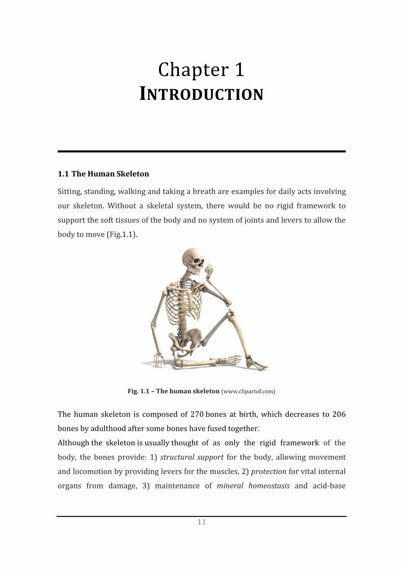
Fig.1.3 - Structure of a long bone - Internal features of a portion of the diaphysis (The McGraw-
Hill Companies, Inc.)
1.2 The Bone Structure
1.2.1 Bone Tissue
The bone tissue is the major structural and supporting connective tissue of the
body, composed of a tough organic matrix that is greatly strengthened by deposits
of calcium salts.
The crystalline salts deposited in the organic matrix of bone are composed
principally of calcium and phosphate. The formula for the major crystalline salt,
known as hydroxyapatite, is Ca10(PO4)6(OH)2.
Average compact bone contains about 30 wt% matrix and 70 wt% salts. Newly
formed bone may have a considerably higher percentage of matrix in relation to
salts.
The organic matrix of bone is 90-95% collagen fibers, while the remaining part is a
homogeneous gelatinous medium called ground substance. The collagen fibers

Chapter 1
14
extend primarily along the lines of tensional force, providing the bone with its
powerful tensile strength.
The ground substance is composed of extracellular fluid plus proteoglycans,
especially chondroitin sulfate and hyaluronic acid. The precise function of each of
these is not known, although they do help to control the deposition of the mineral
phases.
Each bone is composed of two main different bone types: the compact (or cortical)
bone and the spongy (or trabecular) bone. Cortical bone is denser and surrounds
the marrow space, whereas trabecular bone is composed of a honeycomblike
network of trabecular plates and rods interspersed in the bone marrow
compartment. Both cortical and trabecular bone are composed of osteons (Fig.1.4).
Fig.1.4 – Histology of bone tissue (©John Wiley & Sons, Inc.)

Introduction
15
The adult human skeleton is averagely composed of 80% cortical bone and 20%
trabecular bone. However, different bones may have different cortical to trabecular
bone ratio: for example, the vertebrae, the femoral heads and the femoral
diaphysis are chacterized by a ratio equals to about 25:75, 50:50 and 95:5,
respectively.
The bone tissue is characterized by a hierarchical structure that ranges over 9-10
orders of magnitude in length, from the molecular level to the bone structure
(Fig.1.5).
Fig.1.5 – Hierarchical structure of bone – Macroscale arrangements involve both compact/cortical bone at the surface and spongy/trabecular bone in the interior.
The bone is composed of cells embedded in an extracellular matrix, which is an
ordered network assembled from two major nanophases: collagen fibrils made
from type-I collagen molecules (~300 nm long, ~1.5 nm in diameter) and
hydroxyapatite nanocrystals (plate-shaped, 50 nm × 25 nm in size, 1.5–4 nm thick)
distributed along the collagen fibrils. The hydroxyapatite nanocrystals are
preferentially oriented with their c axis parallel to the collagen fibrils, and
arranged in a periodic, staggered array along the fibrils [2]. These two nanophases
make up about 95% of the dry weight of bone. The structures form a tough yet
lightweight, adaptive, self-healing and multifunctional material. Bone derives its
resistance to fracture with a multitude of deformation and toughening mechanisms
operating at many size scales, ranging from the nanoscale structure of its protein
molecules to the macroscopic physiological scale.

Chapter 1
16
1.2.2 Bone Cells
Bone tissue is continuously remodeled through the concerted actions of bone cells,
which include osteogenic cells, osteoblasts, osteoclasts, osteocytes and bone-lining
cells [3] (Fig.1.6).
Fig.1.6 – Types of bone cells (Anatomy and Physiology, Martini, 2007)
Osteoprogenitor cells
The osteoprogenitor cells are stem cells derived from the embryonic mesenchymal
tissue. They are found in the endosteum and the periosteum, and in the central
canals of bones. The osteogenic cells are the only bone cells that divide,
differentiating into osteoblasts which, in turn, are responsible for forming new
bone.
Osteoblasts
Osteoblasts play a very important role in creating and maintaining skeletal
architecture; these cells are responsible for the deposition of bone matrix and for
osteoclasts regulation. Osteoblasts are mononuclear, not terminally differentiated,
specialized cells [4]. When they are active, a large Golgi apparatus and an abundant
rough endoplasmic reticulum is visible. In addition, osteoblasts form tight
junctions with adjacent osteoblasts [5].
As they differentiate they acquire the ability to secrete bone matrix. Ultimately,
some osteoblasts become trapped in their own bone matrix giving rise to
osteocytes.

Introduction
17
Osteoclasts
Osteoclasts are multinucleated giant cells that differentiate from myeloid
precursors under the influence of the cytokines macrophage colony stimulating
factor (MCSF) and receptor activator of NF-kB ligand (RANKL) supplied by
osteoblasts and/or osteocytes [6]. Osteoclasts degrade bone by the polarized
secretion of proteolytic enzymes (e.g., cathepsin K) and acids, which hydrolyze and
solubilize the organic and inorganic components of bone, respectively.
Subsequent to the osteoclastic resorptive phase, coupling mechanisms promote
the recruitment and differentiation of mesenchyme-derived osteoblast progenitors
at the resorption lacunae. After these cells mature into osteoblasts, they line the
eroded bone surface and secrete the organic component of bone, termed osteoid,
which is mineralized over time by the incorporation of hydroxyapatite [7]. As
osteoblasts secrete osteoid, some cells are entrapped within the matrix where
they eventually become osteocytes.
Osteocytes
Osteocytes are the most abundant cells in bone; these cells communicate with each
other and with the surrounding medium through extensions of their plasma
membrane [8].
Osteocytes are embedded in osteons arranged concentrically around the Haversian
canal. An osteocyte resides in a lacuna and connects to other osteocytes through its
processes that extend through the cannaliculi. Mechanical loads on bone induce
fluid flow in the canalicular space.
Therefore, osteocytes are thought to act as mechanosensors, instructing
osteoclasts where and when to resorb bone and osteoblasts where and when to
form it [9].
Chapter 1
18
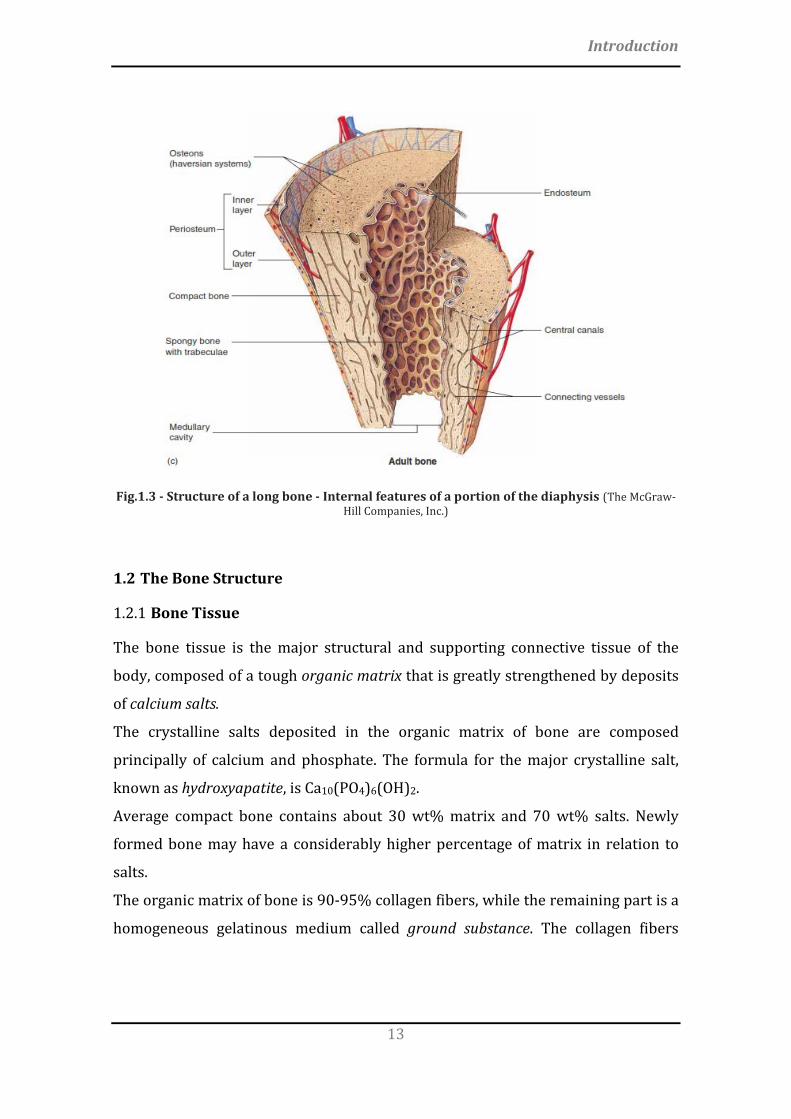
Fig.1.7 – Schematic of the anatomical locations of and mechanical loads experienced by
osteocytes and osteoprogenitor cells [9].
Bone-lining cells
Bone lining cells, or periosteal cells, are flattened in shape, with few cell organelles.
These cells cover the surface of bones and are found to affect both the bone
remodeling and the concentration of minerals in blood and bone tissues. It is
observed that mechanical loading stimulates bone formation by reactivation of
bone-lining cells to become active osteoblasts. Bone-lining cells occupy the
majority of adult bone surface. They serve as an ion barrier separating fluids
percolating through the osteocyte and lacunar canalicular system from the
interstitial fluids.
1.2.3 Bone Modeling and Remodeling
The bone is a complex, living tissue that is constantly adapting to metabolic and
structural demands. Because it is a mineralized tissue, all changes in external
osseous form occur along vascularized periosteal surfaces via uncoupled anabolic
and catabolic modeling events. Modeling changes the shape and size of bones in
response to mechanical loading or wounding. On the other hand, remodeling is

Introduction
19
turnover of bone that is related to bone maturation, skeletal maintenance, and
mineral metabolism.
Bone modeling activity is a mechanically mediated adaptive process supposed to
be controlled by the peak strain of dynamic loading [10, 11] (Fig.1.8).
Fig.1.8 – Frost’s mechanostat shows the relationship of dynamic loading and peak strain
history to: atrophy, physiologic maintenance, hypertrophy, fatigue failure, and spontaneous fracture. R = resorption; F = formation [12].
Sensitive biomechanical feedback of anabolic and catabolic modeling is the
mechanism of growth, adaptation and atrophy of the skeletal system. Disuse
atrophy and overload hypertrophy are the means for sculpting bones and adapting
their mass and orientation to optimally support functional loading.
The bone remodeling begins early in fetal life, and once the skeleton is fully formed
in young adults almost all of the metabolic activity is in this form. The bone
remodeling cycle involves a series of highly regulated steps that depend on the
interactions of two cell lineages, the mesenchymal osteoblastic lineage and the
hematopoietic osteoclastic lineage (Fig.1.9).

Chapter 1
20
Fig.1.9 – Bone remodeling process (©Encyclopaedia Britannica, Inc, 2010)
The initial activation stage, the resting state, involves the interaction of osteoclast
and osteoblast precursor cells, thus leading to the differentiation, migration and
fusion of the large multinucleated osteoclasts. These cells attach to the mineralized
bone surface and initiate bone resorption. Osteoclastic resorption produces
irregular scalloped cavities on the trabecular bone surface, called Howship
lacunae, or cylindrical Haversian canals in cortical bone. Once the osteoclasts have
completed their work of bone removal, there is a “reversal” phase during which
mononuclear cells, which may be of the macrophage lineage, are seen on the bone
surface. The events during this stage are not well understood, but they may involve
further degradation of collagen, deposition of proteoglycans to form the so-called
cement line, and release of growth factors to initiate the formation phase. During
the final formation phase of the remodeling cycle, the cavity created by resorption
can be completely filled in by successive layers of osteoblasts, which differentiate
from their mesenchymal precursors and deposit a mineralizable matrix.
1.3 Bone Tissue Engineering and calcium orthophosphates
Bone tissue engineering is a multidisciplinary research area based on the
understanding of bone structure, bone mechanics and tissue formation to induce
new functional bone tissues. In other words, to successfully regenerate or repair
bone, a precise knowledge of the bone biology and its development is essential.

Introduction
21
Given the structural and metabolic functions of bones, skeletal defects often incur
in considerable morbidity. Conventional medical strategies generally focus on
preventing the causes of diseases; when it comes to repair of tissue defects elicited
by the diseases, mostly rely on natural healing abilities of tissues, failing to cure
irreversible tissue defects. In bone and cartilage, irreversible tissue defects are
caused by aging, trauma, disease, tumors as well as developmental abnormalities.
The role of Bone Tissue Engineering in the field of Regenerative Medicine has been
the topic of substantial research over the past three decades.
Three main pillars of bone tissue engineering were also identified (Fig. 1.10): a
scaffold provides a structure for tissue growth, while cells produce the desired
tissue under biochemical signaling able to affect their growth and phenotype.
Fig.1.10 – Scheme of the three pillars of tissue engineering. To bring tissue engineering into
reality, it is crucial to sufficiently advance and combine the three [13].
The calcium orthophosphates are chemical compounds of wide interest in many
fields of science, including medicine [14], due to their abundance in nature and
presence in living organisms.
By definition, all calcium orthophosphates consist of three major chemical
elements, calcium (oxidation state +2), phosphorus (oxidation state +5) and
oxygen (reduction state -2), as a part of orthophosphate anions.
In particular, calcium orthophosphates have been studied as bone repair materials
for the last 90 years, given their resemblance with the inorganic phase of bones.

Chapter 1
22
The first in vivo use of tricalcium phosphate (TCP) was performed by Albee and
Morrison in 1920 [15]. Despite few early experiments, it was only in the 1970’s
that calcium orthophosphates - mostly hydroxyapatite (HA) - were synthesized,
characterized, and applied [16-19].
Calcium orthophosphates were prepared by sintering (thermal consolidation) as
granules or blocks, porous or dense. Since then, the interest in these materials has
increased. In the mid 1980’s, Brown and Chow [20] discovered the first hydraulic
calcium phosphate cement, i.e. a mixture of calcium phosphate powders and water
that hardened with time at room temperature. This discovery opened up new
perspectives for the use of calcium orthophosphates in the treatment of bone
defects.
Two different categories of calcium phosphate compounds (CaP) can be
distinguished: 1) CaP obtained by precipitation from an aqueous solution at or
around room temperature (low temperature), and 2) CaP obtained by thermal
reactions (high-temperature) [21] (Fig.1.11).
Fig.1.11 – Main calcium phosphate compounds. The first 6 compounds precipitate at room
temperature in aqueous systems. The last 6 compounds are obtained by thermal decomposition or thermal synthesis [21].
A key parameter of calcium phosphate compounds is their solubility (in water): if
the solubility of a CaP is less than the mineral part of bone, it degrades extremely

Introduction
23
slowly, whereas if the solubility of a CaP is greater than that of the mineral part of
bone, it is too easily degraded.
The analysis of the calcium phosphate solubility reveals that at physiological pH
(7.2–7.4) the concentration of Ca and P dissolved from calcium orthophosphates
decreases in the order TTCP > α-TCP > DCPD > DCPA > OCP > β-TCP > HAp
(Fig.1.12). However, in those conditions, HA is the most stable of all calcium
orthophosphates, and in this way it should precipitate as a-TCP dissolution
progresses [22].
Fig.1.12 – Solubility phase diagram for the ternary system Ca(OH)2–H3PO4–H2O, at 37°C: (a) solubility isotherms showing log [Ca] and pH of solution in equilibrium with various salts;
(b) solubility isotherms showing log [P] and pH of the solutions [22]. TTCP: tetracalcium phosphate. DCPA: dicalcium phosphate anhydrous. HAp: precipitated apatite
In the present thesis, the research activity is focused on Bone Tissue Engineering
as regards the synthesis, characterization and optimization of scaffolds based on
hydroxyapatite and tricalcium phosphate for the regeneration of complex-shape
large bone defects.
1.3.1 Cranial injuries and cranioplasty
Cranial injuries involve trauma to the skull and the brain. The skull is tough,
resilient, and provides excellent protection for the brain, but a severe impact or
blow can result in fractures and may be accompanied by injuries to the brain.
Head injuries are dangerous, especially because can lead to permanent disability,
mental impairment and death.

Chapter 1
24
The cranial-encephalic trauma are considered the main cause of head injury both
in Europe and in USA: it is estimated that road accidents are associated with 50%
of mortality [23].
Brain injury incidence is higher in young people showing a peak incidence in
young adults aged 15-24 with secondary peaks in infants and the elderly between
the ages of 70-80.
A skull fracture is a break in one or more of the eight bones that form the cranial
portion of the skull, usually occurring as a result of blunt force trauma. If the force
of the impact is excessive, the bone may fracture at or near the site of the impact
and cause damage to the underlying physical structures contained within the skull
such as the membranes, blood vessels and brain, even in the absence of a fracture.
1.3.1.1 Anatomy of the skull In most of the vertebrates, the skull refers to the bony
structure mainly deputed to the support of the face and of
the protection of the brain, as well as the fixation of the
sense organs’ position to obtain their optimal functions.
Like other anatomical structures, also the skull is
considered to be composed by two main parts: for
humans they are identified as neurocranium, referring to
the vault surrounding the brain, and the viscerocranium, which refers to the bone
surrounding the face. Except for the mandible, the other bones of the skull are
joined together by sutures, almost rigid articulations permitting only very little
movements.
The brain is not directly in contact with the skull bones because of the
interposition of the so called meninges, membranes that envelope the brain and
the spinal cord or the central nervous system. In mammals, three meningeal layer
are recognized: the dura mater, the arachnoid mater and the pia mater (Fig.1.13).

Introduction
25
Fig.1.13 - The meninges (from Wikipedia)
Both the meninges and the cerebrospinal fluid, a colorless body fluid situated
between the arachnoid mater and the pia mater, play a key role in the protection of
the central nervous system.
1.3.1.2 Cranioplasty Cranioplasty is the surgical repair of a bone defects of the skull after a previous
operation or injury (Fig.1.14).
Fig.1.14 – Skull defects and cranioplasty
The first attempts to repair cranial bone date back to 7000 B.C., so that
cranioplasty is considered one of the oldest neurosurgical practices [24].
Over the past centuries a lot of techniques and materials have been introduced as
improvement of neurosurgical care, leading to an increase of the patients surviving
cranial injuries. The aim of cranioplasty is not only a cosmetic issue; also, the
repair of cranial defects gives relief to psychological drawbacks and increases the
social performances.

Chapter 1
26
The cranioplasty is nowadays a mandatory surgical technique following the
Decompressive Craniectomy (DC), a potentially life-saving procedure in patients
with medically intractable intracranial hypertension secondary to severe closed
head injuries or massive strokes. The DC involves the surgical removal of part of
the skull in order to facilitate the neurological recovery of severe head injured
patients.
Procedural and neurological side effects are be to be considered, as the currently
available complex and time-consuming techniques are often unsatisfactory, both
for the surgeon and the patient [25, 26].
The optimal timing for performing a cranioplasty seems to play a key role not only
in avoiding procedure-associated complications, but also in the neurological
outcome of these patients. However, the existent data in the literature are not solid
enough for drawing any safe conclusions regarding the ideal timing for performing
a cranioplasty [27].
An example of custom-made scaffold for regenerative cranioplasty is given by the
Custom Bone Service cranial prosthesis from Fin-Ceramica S.p.A, Faenza, Italy [28,
29], consisting in a porous apatitic structure. It may be defined as a biomimetic
framework because it is recognised as “self” by the recipient bone, thus avoiding
any immunological reaction. Furthermore, it is characterised by a high macro
(diameter>150 µm), micro (diameter<10µm) and interconnected porosity
reaching 70%, allowing high permeability for the cells and blood coming from the
recipient bone.
The production begins with the raw digital data obtained during the CT scan; its
extensive elaboration allows the creation of essential 3D computer reproduction of
the patient’s skull. Only through the raw data elaboration of the CT scan and the
subsequent 3D computer reproduction, it is possible to construct a 3D synthetic
model of the patient’s skull using stereolithography. From this 3D synthetic model,
the first prototype of the custom-made implant is produced. Together with the
surgeon, the custom-made prototype is thoroughly reviewed for prospective
modifications. This step is extremely important to ensure a custom-made implant
which provides a superior aesthetic outcome for the patient and a straightforward

Introduction
27
surgical technique for the surgeon. Once the surgeon has approved the custom-
made prototype, the final implant is precisely prepared via Replica method,
refined, controlled and sterilized prior to shipment to the hospital for
implantation.
1.3.1.3 Porous bioceramic scaffolds Materials containing tailored porosity exhibit special properties and features that
usually cannot be achieved by their conventional dense counterparts.
In this respect, in the last decades the porous ceramics have been extensively
studied for a wide range of applications and several processing methods were
proposed for their preparation [30-34].
The artificial bone substitutes represent one of the most challenging application,
especially due to the difficulty of mimicking the properties of the natural bone [35].
Hydroxyapatite (HA) is widely recognized as the golden material for bone and
teeth regeneration, due to its close similarity with the inorganic part of bone,
which confer excellent biocompatibility and ability to permit new bone formation
and adhesion [36-39]. However, in spite a variety of techniques for scaffold
development has been investigated so far [30-34], the repeatable and reliable
production of HA scaffolds with bone-mimicking pore structure and adequate
mechanical strength is still a big challenge [33].
The traditional processes reported in literature for the production of macroporous
ceramics are: partial sintering, sacrificial fugitives, replica templates and direct
foaming (Fig.1.15).

Chapter 1
28
Fig.1.15 – Representative fabrication processes of macroporous ceramics [33]
Partial sintering
The partial sintering of powder compact is the most conventional and frequently
used approach to fabricate porous ceramic materials. The high temperature
thermal treatment induces surface diffusion or evaporation-condensation
phenomena, leading to a homogeneus porous structure when sintering is
terminated before fullt densified. Pore size and porosity are controlled by the size
of starting powders and degree of partial sintering, respectively.
Sacrificial fugitives
The sacrificial template technique usually foresees to prepare a biphasic composite
consisting of a continuous matrix of ceramic powders and a dispersed sacrificial
phase that is initially homogeneously distributed throughout the matrix and finally
extracted to generate pores inside the microstructure. Porosity is controlled by the
amount of the agents. This approach is useful particularly for obtaining high open
porosity.
Replica Templates
The Replica method is considered as the first method used for the production of
macroporous ceramics. It involves the impregnation of a polymeric cellular
structure with a ceramic suspension in order to produce a macroporous ceramic

Introduction
29
exhibiting the same morphology as the original template. The success of this
method is attributed to its simplicity and flexibility. However, some critical aspects
have to be strictly controlled and optimized, such as the rheological behavior of the
ceramic suspensions (shear-thinning), the presence of binders or plasticizers in
the initial suspension to avoid the strut cracking during pyrolisis and the final
thermal treatment parameters (heating rate, high temperature). In this respect, a
disadvantage of this method is the cracking of the struts after thermal treatment,
leading to a severe degradation of the mechanical performance of the structure.
Direct foaming
The direct foaming method was stated to be a low-cost and easy process that can
provide pore volumes in the range 40-97% by incorporating a gas (e.g. air) into a
ceramic suspension, that is subsequently dried and sintered. The total porosity of
directly foamed ceramics is proportional to the amount of gas incorporated into
the suspension or liquid medium during the foaming process. The pore size, on the
other hand, is determined by the stability of the wet foam before setting takes
place.
Cellular structures prepared by direct foaming usually exhibit considerably higher
mechanical strength than those obtained by other template-based techniques,
mainly due to the strongly reduced occurrence of flaws in the cell struts [34].
Liquid foams are thermodynamically unstable systems due to their high gas-liquid
interfacial area. Several physical processes take place in wet foams to decrease the
overall system free energy, leading to foam destabilization. The main
destabilization mechanisms are: drainage, coalescence, Ostwald ripening [34].
Drainage is the physical separation between the gaseous and liquid phases of the
foam because of the effect of gravity: light gas bubbles move upwards forming a
denser foam layer on the top, while the heavier liquid phase is concentrated on the
bottom (Fig. 1.16a).
Coalescence takes place when the thin films formed after drainage are not stable
enough to keep the touching cells apart, resulting in the association of neighboring
bubbles: the stability of the thin films is determined by the attractive and repulsive
interactions between bubbles (Fig. 1.16b). Coalescence is favored by attractive van

Chapter 1
30
der Waals forces and can only be hindered by providing steric and/or electrostatic
repulsion among the interacting bubbles.
(a) (b)
Fig.1.16: Foam drainage (a), coalescence: schematic dependence of the disjoining pressure among two interacting gas bubbles as a function of their distance (b).
Foams can be tailored to efficiently prevent drainage and coalescence processes,
but in long-term the Ostwald ripening phenomenon can occurs, leading to the
destabilization of the system due to the difference in Laplace pressure between
bubbles of different sizes.
Surfactants and biomolecules adsorbed at the gas–liquid interface can slow down
this coarsening process by decreasing the interfacial energy [34].
1.3.1.4 Hydroxyapatite The hydroxyapatite is a naturally occurring mineral form of calcium apatite with
the formula Ca5(PO4)3(OH), but is usually written Ca10(PO4)6(OH)2 to denote that
the crystal unit cell comprises two entities (Fig.1.17). It is also the main inorganic
component of biological hard tissues such as bones and teeth of vertebrates.

Introduction
31
Fig.1.17 – Bidimensional schematic representation of the hydroxyapatite crystal lattice
Biological apatite is an inorganic calcium phosphate salt in apatite form and
nanosize with a biological derivation. Additionally, due to the similarity in
chemical compositions and structure, together with its outstanding bioactivity and
biocompatibility, biological apatite has been used as bone substitutes for the
reconstruction of bone defect in oral implantology, periodontology, oral, and
maxillofacial surgery as well as orthopedics. Given the significant role of biological
apatite in the structure and function of biological tissues and its clinical
applications, numerous studies have been carried out in the investigation of its
basic physiochemical and biological properties.
The composition and structure of synthetic precipitated apatite (HAp) have been
studied as potential precursor of biological apatite.
The structure of apatite allows for wide compositional variations because of its
ability in detaining different ions in its three sublattices. In detail, the site of Ca2+
may be occupied by bivalent or monovalent cations such as Sr2+, Ba2+, Mg2+, Na+,
and K+, the site of P could be substituted by atoms such as C, As, V, S, while
hydroxyl (OH−) may be replaced by OD−, CO32−, F−, Cl− or even be left vacant [40]
(Fig.1.18).

Chapter 1
32
Fig.1.18– Schematic drawing of partial dissolution/precipitation of biological apatite in vivo
and ionic substitutions in the crystal of HAp [40]
Two different crystal forms were reported: hexagonal, with the lattice parameters
𝑎 = 𝑏 = 9.432 Å, 𝑐 = 6.881 Å, and 𝛾 = 120° [41] and monoclinic, with the lattice
parameters 𝑎 = 9.421 Å, 𝑏 = 2𝑎, 𝑐 = 6.881 Å, and 𝛾 = 120° [42].
Each crystal is shaped like a long, flat plate. The relative ratio of calcium to
phosphorus can vary markedly under different nutritional conditions, the Ca/P
ratio on a weight basis varying between 1.3 and 2.0.
1.3.2 Spinal injuries and vertebroplasty
1.3.2.1 Anatomy of the spine The vertebral column, also known as the backbone or spine, is a bony skeletal
structure found in vertebrates. The spine is made of 33 individual bones stacked
one on top of the other (Fig.1.19).

Introduction
33
Fig.1.19 – Anatomy of the vertebral column
The vertebrae are numbered and divided into five regions: cervical, thoracic,
lumbar, sacrum, and coccyx. Only the top 24 bones are moveable, while the
vertebrae of the sacrum and coccyx are fused together. The vertebrae in each
region have unique features that help them perform their functions.
Ligaments and muscles connect the bones together and keep them aligned. The
spinal column provides the main support for your body, allowing you to stand
upright, bend, and twist.
Protected deep inside the bones, the spinal cord connects your body to the brain,
allowing movement of your arms and legs (Fig.1.20).

Chapter 1
34
Fig.1.20 – Axial (overhead) view of a vertebra and structure of the spinal cord
(http://keckmedicine.adam.com/).
Strong muscles and bones, flexible tendons and ligaments, and sensitive nerves
contribute to a healthy spine. Keeping your spine healthy is vital if you want to live
an active life without back pain.
1.3.2.2 Osteoporosis and vertebroplasty Osteoporosis is defined as a systemic skeletal disorder characterized by low bone
mass and micro-architectural deterioration of bone tissue, with a consequent
increase in bone fragility and susceptibility to fracture (Fig.1.21).
The Bone Mineral Density (BMD) is the amount of bone mass per unit volume
(volumetric density, g/cm3), that can be measured in vivo by densitometric
techniques.
Because the BMD in the young healthy population is normally distributed [43] and
the bone loss mainly occurs with advancing age, the prevalence of osteoporosis
increases with age.
The prevalence of osteoporosis in the EU is estimated at 27.6 million in 2010 (22
million of women and 5.6 million of men) [44].

Introduction
35
(a) (b)
Fig.1.21 – Vertebral body’s trabecular structure: healthy bone (a) and osteoporotic bone (b)
The description of osteoporosis captures the notion that low bone mass is an
important component of the risk of fracture, but other abnormalities such as
micro-architectural deterioration contribute to skeletal fragility.
Physical disability, advancing age and/or exposure to microgravity increase the
risk of suffering from osteoporosis, and such disuse osteoporosis is associated with
huge economic and health burden.
The bone loss, in general, refers to a reduction of bone mass in relation to bone
volume, while the ratio of bone mineral to collagen remains unchanged. The loss of
trabecular bone is more rapid and dramatic, while the cortical bone loss continues
for a longer period [45].
The typical sites of osteoporosis fracture are hip, vertebra and wrist, but also
homer, ribs, tibia and fibula [46].
Among them, the osteoporotic vertebral fractures are associated with considerable
reduction of quality of life, morbidity and mortality. Back pain in the majority of
these patients is treated with prolonged bed-rest, local and systemic analgesia, and
bracing. However, the extension of bed-rest in these patients results in increased
bone loss, muscle weakness and joint stiffness [47].
A possible alternative is the vertebroplasty, a surgical procedure that involves the
percutaneous injection of a bone cement into the fractured vertebral body, to
provide mechanical support and relief from the pain. Vertebroplasty is considered

Chapter 1
36
a minimally invasive surgical procedure because the procedure is performed
through a small puncture in the patient's skin, instead of an open incision. A biopsy
needle is guided into the fractured vertebra under X-ray guidance and a bone
cement is injected directly into the fractured vertebra with the goal of creating a
sort of internal cast. Then, the needle is removed and the cement hardens,
stabilizing the bone (Fig.1.22).
Fig.1.22 – Vertebroplasty procedure
1.3.2.3 Bone cements Injectable cements addressed to bone healing are a subject of major interest and
intense investigation, as they can be delivered by minimal invasive surgery and,
benefiting from the ability of self-hardening in situ, they may adequately stabilize
bone defects. Particular interest is also addressed to vertebral fractures, due to
trauma or osteoporosis-related bone weakening, mainly treated with
vertebroplasty/kyphoplasty procedures since decades [48-52]. However, complete
bone regeneration still remains an unsolved clinical need, mainly due to the lack of
bone cements endowed with suitable bioactivity, osteoconductivity and bio-
resorption ability.
To date, two main cathegories of bone cements have been developed, based on
polymers (especially acrylic formulations) and calcium phosphates.
Acrylic Bone cements
Poly(methylmethacrylate) (PMMA)-based bone cement, commonly known as
acrylic bone cement, has been used For over 40 years, for fixation of total joint
replacement prostheses to periprosthetic bone. The acrylic bone cements on the

Introduction
37
market consist of two components: a liquid and a powder, which are mixed in the
operating room until they become dough-like and then applied to stabilize a joint
replacement prosthesis or directly injected into damaged vertebral bodies.
The basic component of acrylic bone cements is methylmethacrylate (MMA), which
is an ester of methacrylic acid (Fig.1.23).
Fig.1.23 – Polymerization reaction typical of PMMA-based cements
Calcium phosphate bone cements (CPCs)
Calcium phosphate cements (CPCs) were discovered in the 1980s by Brown and
Chow [53] and LeGeros et al. [54]. The first commercial CPC products were
introduced in the 1990s for treatment of maxillo-facial defects as well as for
treatment of fractures. Since then, new cement formulations have been developed
that fulfill specific requirements for other applications, such as bone augmentation,
reinforcement of osteoporotic bones, fixation of metallic implants in weakened
bone, spinal fractures and vertebroplasty.
CPCs are hydraulic cements. In general, CPCs are formed by a combination of one
or more calcium orthophosphate powders, which upon mixing with a liquid phase,
usually water or an aqueous solution, form a paste that is able to set and harden:
the dissolution of the precursor powder via a hydraulic reaction and the
precipitation of a thermodynamically more stable setting product occur. In this
respect, unlike acrylic bone cements, which harden through a polymerization
reaction, CPCs set as a result of a dissolution and precipitation process (Fig.1.24).

Chapter 1
38
Fig.1.24 - Classification of calcium phosphate cements, with examples of the most common
formulations [55].
The entanglement of the precipitated crystals is responsible for cement hardening.
Despite the large number of possible formulations, the CPCs developed up to
nowhave only two different end products, precipitated hydroxyapatite (HA) or
brushite (DCPD).
This in fact is a predictable situation since hydroxyapatite is the most stable
calcium phosphate at pH>4.2 and brushite the most stable one at pH<4.2.
When set, the apatitic CPCs consist of a network of calcium phosphate crystals,
with a chemical composition and crystal size that can be tailored to closely
resemble the biological hydroxyapatite occurring in living bone.
The CPCs leading to the formation of HA or calcium deficient HA (CDHA) can be
classified in two main categories, which are summarized in Fig.1.25: 1)
monocomponent CPCs, in which a single calcium phosphate compound, alpha
tricalcium phosphate (α-TCP) hydrolyses to CDHA without varying the Ca/P ratio,
according to the reported chemical formula; 2) Multicomponent CPCs, in which
two or more calcium phosphates, some more acidic and the other basic, set
following an acid–base reaction.

Introduction
39
1.3.2.4 Tricalcium phosphate (TCP) The tricalcium phosphate (Ca3(PO4)2), bioresorbable material, exists in three
different polymorphs: the low-temperature β-TCP, and the high-temperature
forms, α- and α’-TCP. The last one lacks practical interest because it only exists at
temperatures >1430°C and reverts almost instantaneously to α-TCP on cooling
below the transition temperature. In contrast, β-TCP is stable at room temperature
and transforms reconstructively at 1125 °C to α-TCP, which can be retained during
cooling to room temperature [22].
Cell parameters (a, b, c, α, β and γ), cell volume (V), number of formula units per
cell (Z), volume per formula unit (V), theoretical density (Dth0) and the projections
of the unit cells along the [0 0 1] direction are shown in Fig.1.25.
Property β-TCP α-TCP α’-TCP Symmetry Rhombohedral Monoclinic Hexagonal Space Group R3C P21/a P63/mmc a (nm) 1.04352 1.2859 0.53507 b (nm) 1.04352 2.7354 0.53507 c (nm) 3.74029 1.5222 0.7684 α (°) 90 90 90 β (°) 90 126.35 90 γ (°) 120 90 120 Z 21 24 1 V (nm3) 3.5272 4.31 0.19052 V0 (nm3) 0.1680 0.18 0.19052 Dth (g · cm3) 3.066 2.866 2.702
(a) (b)
Fig.1.25 – (a) Structural data of α-TCP and its polymorphs. (b) calculated X-ray diffraction pattern of a-TCP and its polymorphs [22]
The difference in packing densities of the three polymorphs is consistent with
thermodynamic considerations and with their stability temperature ranges.
The structural differences between β- and α-polymorphs of TCP are responsible
for their different chemical and biological properties, among them, solubility and
biodegradability.
The α-TCP is characterized by higher solubility than β-TCP, so that in aqueous
solutions the dissolution of α-TCP proceeds faster than β-TCP, as reported [56, 57].
β-TCP is used mainly for preparing biodegradable bioceramics shaped as dense
and macro-porous granules and blocks, whereas the more soluble and reactive α-
TCP is used mainly as a fine powder in the preparation of calcium phosphate

Chapter 1
40
cements. Both β- and α-TCP materials are used in clinics for bone repair and
remodelling applications.
1.4 References
[1] Clarke B. Normal Bone Anatomy and Physiology. Clin J Am Soc Nephro. 2008;3:S131-S9. [2] Wegst UGK, Bai H, Saiz E, Tomsia AP, Ritchie RO. Bioinspired structural materials. Nat Mater. 2015;14:23-36. [3] Cowin SC. Bone Mechanics Handbook, Second Edition: Taylor & Francis; 2001. [4] Caetano-Lopes J, Canhao H, Fonseca JE. Osteoblasts and bone formation. Acta reumatologica portuguesa. 2007;32:103-10. [5] Mackie EJ. Osteoblasts: novel roles in orchestration of skeletal architecture. The international journal of biochemistry & cell biology. 2003;35:1301-5. [6] Boyle WJ, Simonet WS, Lacey DL. Osteoclast differentiation and activation. Nature. 2003;423:337-42. [7] Sims NA, Martin TJ. Coupling the activities of bone formation and resorption: a multitude of signals within the basic multicellular unit. BoneKEy reports. 2014;3:481. [8] Knothe Tate ML, Adamson JR, Tami AE, Bauer TW. The osteocyte. The international journal of biochemistry & cell biology. 2004;36:1-8. [9] Chen JH, Liu C, You L, Simmons CA. Boning up on Wolff's Law: mechanical regulation of the cells that make and maintain bone. Journal of biomechanics. 2010;43:108-18. [10] Frost HM. Bone Mass and the Mechanostat - a Proposal. Anatomical record. 1987;219:1-9. [11] Frost HM. Skeletal Structural Adaptations to Mechanical Usage (Satmu) .1. Redefining Wolff Law - the Bone Modeling Problem. Anatomical record. 1990;226:403-13. [12] Roberts WE, Huja S, Roberts JA. Bone modeling: biomechanics, molecular mechanisms, and clinical perspectives. Seminars in Orthodontics.10:123-61. [13] Ohba S, Yano F, Chung U-i. Tissue engineering of bone and cartilage. IBMS BoneKEy. 2009;6:405-19. [14] Dorozhkin SV. Calcium orthophosphates: occurrence, properties, biomineralization, pathological calcification and biomimetic applications. Biomatter. 2011;1:121-64. [15] Albee FH. Studies in Bone Growth: Triple Calcium Phosphate as a Stimulus to Osteogenesis. Annals of surgery. 1920;71:32-9. [16] Getter L, Bhaskar SN, Cutright DE, Perez B, Brady JM, Driskell TD, et al. Three biodegradable calcium phosphate slurry implants in bone. Journal of oral surgery. 1972;30:263-8. [17] Jarcho M, Kay JF, Gumaer KI, Doremus RH, Drobeck HP. Tissue, cellular and subcellular events at a bone-ceramic hydroxylapatite interface. J Bioeng. 1977;1:79-92.

Introduction
41
[18] Rejda BV, Peelen JG, de Groot K. Tri-calcium phosphate as a bone substitute. J Bioeng. 1977;1:93-7. [19] Roy DM, Linnehan SK. Hydroxyapatite formed from coral skeletal carbonate by hydrothermal exchange. Nature. 1974;247:220-2. [20] Brown WE, Chow LC. Dental restorative cement pastes. 1985. [21] Bohner M. Calcium orthophosphates in medicine: from ceramics to calcium phosphate cements. Injury. 2000;31:S37-S47. [22] Carrodeguas RG, De Aza S. alpha-Tricalcium phosphate: synthesis, properties and biomedical applications. Acta biomaterialia. 2011;7:3536-46. [23] Corrigan JD, Selassie AW, Orman JA. The epidemiology of traumatic brain injury. J Head Trauma Rehabil. 2010;25:72-80. [24] Barker FG. Repairing Holes in the Head: A History of Cranioplasty. Neurosurgery. 1997;41:999. [25] Chaturvedi J, Botta R, Prabhuraj AR, Shukla D, Bhat DI, Devi BI. Complications of cranioplasty after decompressive craniectomy for traumatic brain injury. British journal of neurosurgery. 2015:1-5. [26] Zanaty M, Chalouhi N, Starke RM, Clark SW, Bovenzi CD, Saigh M, et al. Complications following cranioplasty: incidence and predictors in 348 cases. Journal of neurosurgery. 2015;123:182-8. [27] Tasiou A, Vagkopoulos K, Georgiadis I, Brotis AG, Gatos H, Fountas KN. Cranioplasty optimal timing in cases of decompressive craniectomy after severe head injury: a systematic literature review. Interdisciplinary Neurosurgery. 2014;1:107-11. [28] Staffa G, Barbanera A, Faiola A, Fricia M, Limoni P, Mottaran R, et al. Custom made bioceramic implants in complex and large cranial reconstruction: a two-year follow-up. Journal of cranio-maxillo-facial surgery : official publication of the European Association for Cranio-Maxillo-Facial Surgery. 2012;40:e65-70. [29] Staffa G, Nataloni A, Compagnone C, Servadei F. Custom made cranioplasty prostheses in porous hydroxy-apatite using 3D design techniques: 7 years experience in 25 patients. Acta neurochirurgica. 2007;149:161-70; discussion 70. [30] Colombo P. Materials science. In praise of pores. Science. 2008;322:381-3. [31] Deville S. Freeze-casting of porous ceramics: A review of current achievements and issues. Adv Eng Mater. 2008;10:155-69. [32] Messing GL, Stevenson AJ. Materials science. Toward pore-free ceramics. Science. 2008;322:383-4. [33] Ohji T, Fukushima M. Macro-porous ceramics: processing and properties. Int Mater Rev. 2012;57:115-31. [34] Studart AR, Gonzenbach UT, Tervoort E, Gauckler LJ. Processing routes to macroporous ceramics: A review. J Am Ceram Soc. 2006;89:1771-89. [35] Shackelford JF. Bioceramics: Taylor & Francis; 2003. [36] Dutta SR, Passi D, Singh P, Bhuibhar A. Ceramic and non-ceramic hydroxyapatite as a bone graft material: a brief review. Irish journal of medical science. 2015;184:101-6. [37] Pepla E, Besharat LK, Palaia G, Tenore G, Migliau G. Nano-hydroxyapatite and its applications in preventive, restorative and regenerative dentistry: a review of literature. Annali di stomatologia. 2014;5:108-14.

Chapter 1
42
[38] Rivera-Muñoz EM. Hydroxyapatite-Based Materials: Synthesis and Characterization2011. [39] Venkatesan J, Kim SK. Nano-hydroxyapatite composite biomaterials for bone tissue engineering--a review. Journal of biomedical nanotechnology. 2014;10:3124-40. [40] Liu Q, Huang SS, Matinlinna JP, Chen ZF, Pan HB. Insight into Biological Apatite: Physiochemical Properties and Preparation Approaches. Biomed Res Int. 2013. [41] Posner AS, Perloff A, Diorio AF. Refinement of the hydroxyapatite structure. Acta Crystallographica. 1958;11:308-9. [42] Elliott JC, Mackie PE, Young RA. Monoclinic hydroxyapatite. Science. 1973;180:1055-7. [43] Strom O, Borgstrom F, Sen SS, Boonen S, Haentjens P, Johnell O, et al. Cost-effectiveness of alendronate in the treatment of postmenopausal women in 9 European countries--an economic evaluation based on the fracture intervention trial. Osteoporosis international : a journal established as result of cooperation between the European Foundation for Osteoporosis and the National Osteoporosis Foundation of the USA. 2007;18:1047-61. [44] Hernlund E, Svedbom A, Ivergard M, Compston J, Cooper C, Stenmark J, et al. Osteoporosis in the European Union: medical management, epidemiology and economic burden. A report prepared in collaboration with the International Osteoporosis Foundation (IOF) and the European Federation of Pharmaceutical Industry Associations (EFPIA). Archives of osteoporosis. 2013;8:136. [45] Robling AG, Castillo AB, Turner CH. Biomechanical and molecular regulation of bone remodeling. Annu Rev Biomed Eng. 2006;8:455-98. [46] Kanis JA, Adachi JD, Cooper C, Clark P, Cummings SR, Diaz-Curiel M, et al. Standardising the descriptive epidemiology of osteoporosis: recommendations from the Epidemiology and Quality of Life Working Group of IOF. Osteoporosis international : a journal established as result of cooperation between the European Foundation for Osteoporosis and the National Osteoporosis Foundation of the USA. 2013;24:2763-4. [47] Dionyssiotis Y. Management of osteoporotic vertebral fractures. Int J Gen Med. 2010;3:167-71. [48] Bohner M. Calcium orthophosphates in medicine: from ceramics to calcium phosphate cements. Injury. 2000;31 Suppl 4:37-47. [49] Poitout DG. Biomechanics and Biomaterials in Orthopedics. 1st ed: Springer; 2004 [50] Saint-Jean SJ, Camire CL, Nevsten P, Hansen S, Ginebra MP. Study of the reactivity and in vitro bioactivity of Sr-substituted alpha-TCP cements. Journal of materials science Materials in medicine. 2005;16:993-1001. [51] Watts NB, Harris ST, Genant HK. Treatment of painful osteoporotic vertebral fractures with percutaneous vertebroplasty or kyphoplasty. Osteoporosis international : a journal established as result of cooperation between the European Foundation for Osteoporosis and the National Osteoporosis Foundation of the USA. 2001;12:429-37.

Introduction
43
[52] Xue W, Dahlquist K, Banerjee A, Bandyopadhyay A, Bose S. Synthesis and characterization of tricalcium phosphate with Zn and Mg based dopants. Journal of materials science Materials in medicine. 2008;19:2669-77. [53] Brown WE, Chow LC. A new calcium phosphate water setting cement. Cements research progress: Amer Cer Soc; 1986. p. 352-79. [54] LeGeros R., Chohayeb A., Shulman A. Apatitic calcium phosphates: possible dental restorative materials. Journal of dental research. 1982;61. [55] Ginebra MP, Canal C, Espanol M, Pastorino D, Montufar EB. Calcium phosphate cements as drug delivery materials. Advanced drug delivery reviews. 2012;64:1090-110. [56] Chow LC. Calcium phosphate cements. Monographs in oral science. 2001;18:148-63. [57] Wang L, Nancollas GH. Calcium orthophosphates: crystallization and dissolution. Chemical reviews. 2008;108:4628-69.

44

45
2.1 X-Ray Diffraction (XRD)
X-ray diffraction (XRD) is a non-destructive analytical technique primarily used for
phase identification of a crystalline material. The material is finely ground,
homogenized and the average bulk phase composition is analyzed.
XRD is based on constructive interference of monochromatic X-rays and the
crystalline material. The X-rays are generated by a cathode ray tube, filtered to
produce monochromatic radiation, collimated to concentrate and directed towards
the sample.
The interaction of the incident X-rays with the sample produces constructive
interference and a diffracted ray when the Bragg's law is statisfied (Fig.2.1).
Fig.2.1 – Bragg’s law and constructive interference
The phase composition of the material is investigated by comparing diffraction
data against a database of Powder Diffraction Files (International Centre for
Diffraction Data - ICDD).
Chapter 2 OVERVIEW OF METHODS
Chapter 2
46
When coupled with Rietveld refinement techniques, XRD may also provide
structural information, such as unit cell dimensions and lattice strains.
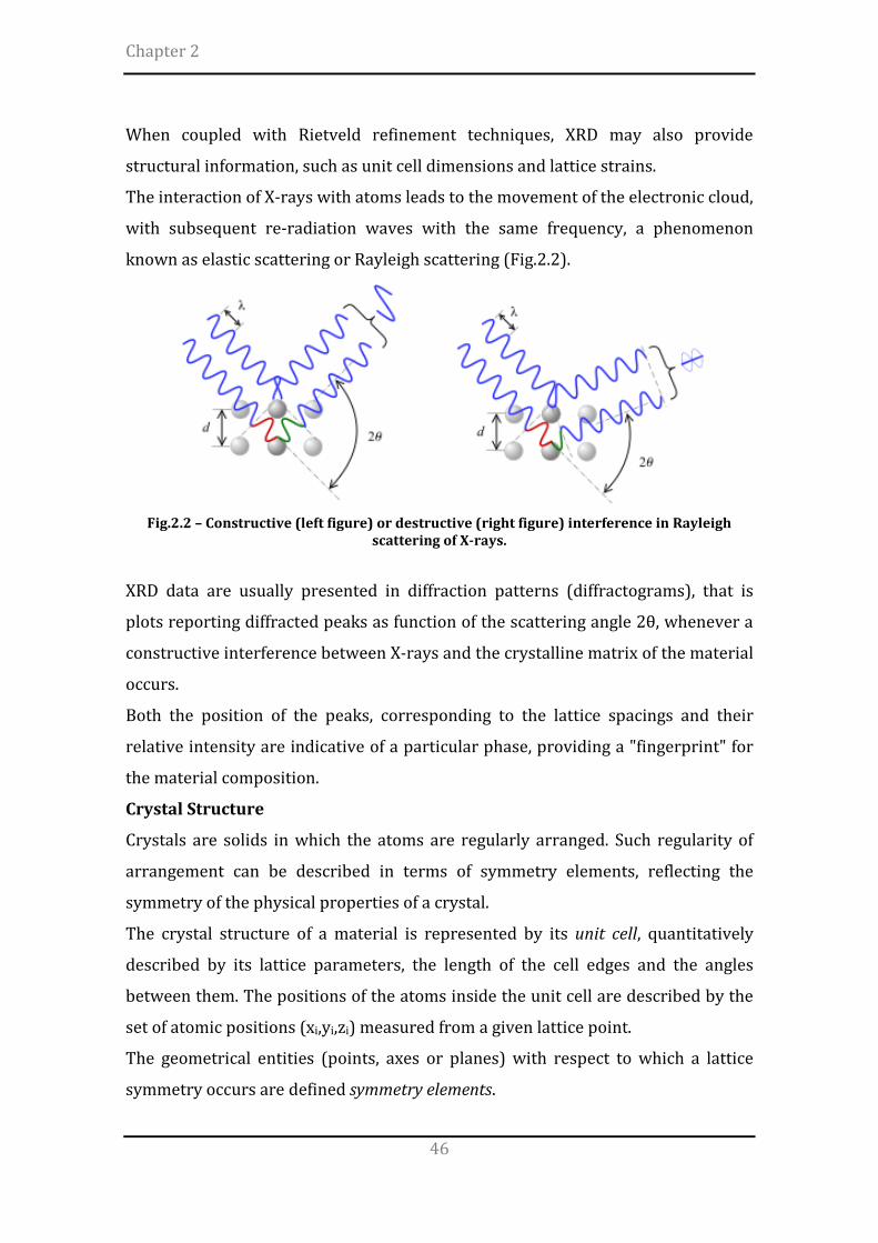
The interaction of X-rays with atoms leads to the movement of the electronic cloud,
with subsequent re-radiation waves with the same frequency, a phenomenon
known as elastic scattering or Rayleigh scattering (Fig.2.2).
Fig.2.2 – Constructive (left figure) or destructive (right figure) interference in Rayleigh
scattering of X-rays.
XRD data are usually presented in diffraction patterns (diffractograms), that is
plots reporting diffracted peaks as function of the scattering angle 2θ, whenever a
constructive interference between X-rays and the crystalline matrix of the material
occurs.
Both the position of the peaks, corresponding to the lattice spacings and their
relative intensity are indicative of a particular phase, providing a "fingerprint" for
the material composition.
Crystal Structure
Crystals are solids in which the atoms are regularly arranged. Such regularity of
arrangement can be described in terms of symmetry elements, reflecting the
symmetry of the physical properties of a crystal.
The crystal structure of a material is represented by its unit cell, quantitatively
described by its lattice parameters, the length of the cell edges and the angles
between them. The positions of the atoms inside the unit cell are described by the
set of atomic positions (xi,yi,zi) measured from a given lattice point.
The geometrical entities (points, axes or planes) with respect to which a lattice
symmetry occurs are defined symmetry elements.

Overview of Methods
47
By using the symmetry elements it is possible to define the symmetry operations,
namely the virtual motions of the smallest asymmetrical unit around a
symmetrical center.
Complex symmetry operations lead to space groups, the most detailed level to
describe the symmetry properties of the crystal, such as cleavage, electronic band
structure and optical properties.
Although there are an infinite number of ways to specify a unit cell, for each crystal
structure there is a conventional unit cell, which is chosen to display the full
symmetry of the crystal. However, the conventional unit cell is not always the
smallest possible choice.
A primitive unit cell of a particular crystal structure is the smallest volume
completely filled by stacked atoms.
In a unit cell each atom has an identical arrangement of the neighboring atoms,
while in a primitive cell each atom may also have different local atoms
arrangements. The crystal structure consists of the same group of atoms, the basis,
positioned around each and every lattice point. This group of atoms therefore
repeats indefinitely in three dimensions according to the arrangement of one of the
14 Bravais lattices (Fig.2.3).
The possible lattice centrings are:
• P: Primitive centring, lattice points on the cell corners only;
• I: Body centred, one additional lattice point at the center of the cell;
• F: Face centred, one additional lattice point at centre of each of the faces of
the cell;
• C: Centred on a single face, one additional lattice point at the centre of one
of the cell faces

Chapter 2
48
Fig.2.3 – The 7 crystalline systems and the 14 Bravais lattices
Miller indices
The Miller indices are useful notation tools in crystallography to identify the
different planes and direction of a Bravais lattice. A reticular plane is identified by
three integers h, k, l, the Miller indices, reported as (hkl). Such indices are vectors,
reciprocals of the intercepts of the plane on the axes x, y, z.
Size and Strain Broadening
The width of a diffraction peak, B, is related to several factors, including:
1. instrumental factors
2. the presence of lattice defects
3. strain dishomogeneity among the grains
4. the size of the crystallites
Overview of Methods
49
Analysis of XRD peak profiles indicated that full-width at half-maximum (FWHM)
is sensitive to the variation in microstructure and stress–strain accumulation in
the material.
Presence of tensile stress in the material causes increase in the FWHM while
relaxation of tensile stress decreases FWHM.
The Scherrer equation [1] can be used to estimate the size of the crystallite
( )θ
λθcos
2D
KB =
where B is the peak width corrected for the instrumental broadening, θ is the
diffraction angle, K is a form factor, usually taken as 0.9, λ is the wavelength of the
incident radiation and D is the crystallite average size.
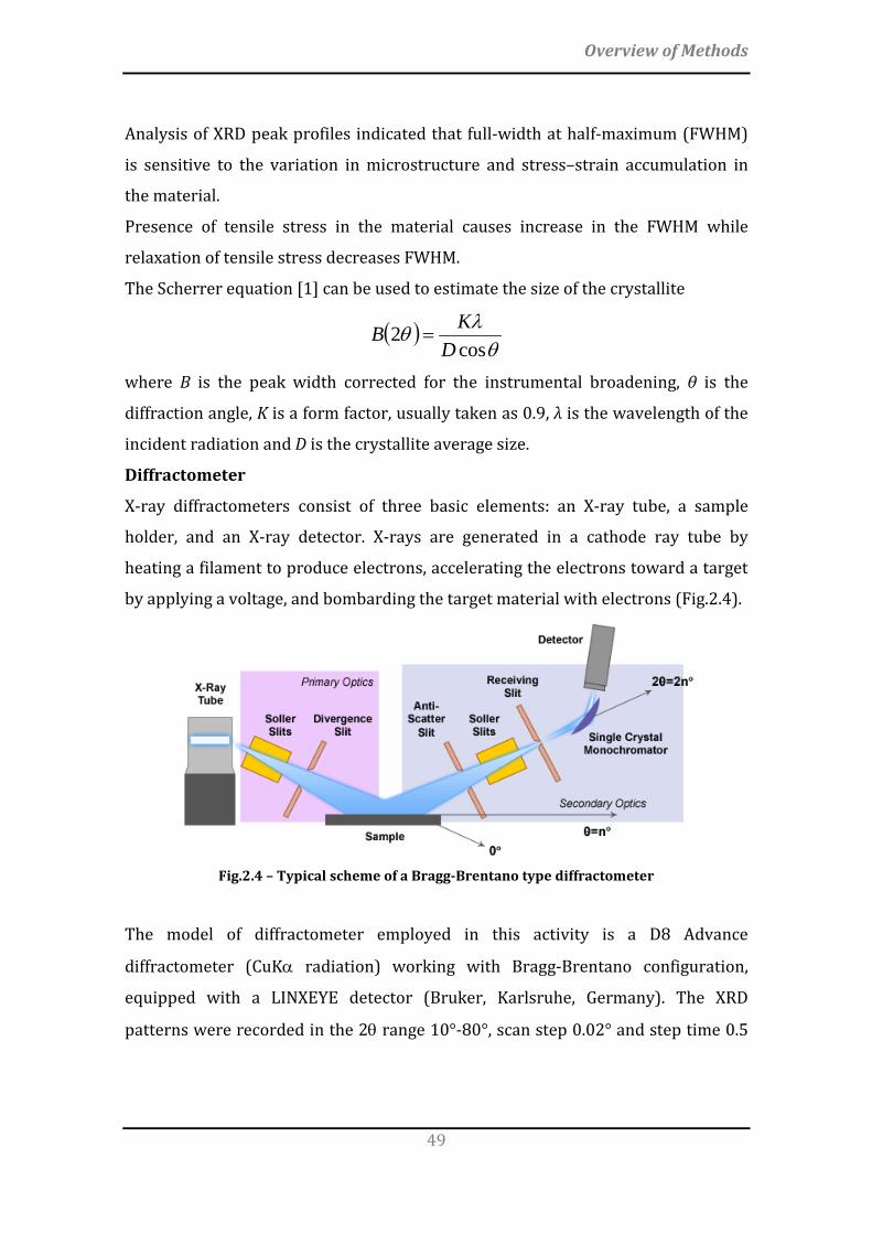
Diffractometer
X-ray diffractometers consist of three basic elements: an X-ray tube, a sample
holder, and an X-ray detector. X-rays are generated in a cathode ray tube by
heating a filament to produce electrons, accelerating the electrons toward a target
by applying a voltage, and bombarding the target material with electrons (Fig.2.4).
Fig.2.4 – Typical scheme of a Bragg-Brentano type diffractometer
The model of diffractometer employed in this activity is a D8 Advance
diffractometer (CuKα radiation) working with Bragg-Brentano configuration,
equipped with a LINXEYE detector (Bruker, Karlsruhe, Germany). The XRD
patterns were recorded in the 2θ range 10°-80°, scan step 0.02° and step time 0.5

Chapter 2
50
seconds. The lattice parameters refinement was performed according to the
Rietveld method (TOPAS 4.2 software).
2.2 Scanning Electron Microscopy (SEM)
The scanning electron microscope is a device able to provide high magnification
images of a sample (up to 200000x) with both resolution and field depth higher
than the conventional optical microscope.
The image is obtained by “exploring” the surface of the sample with a high energy
electron beam, while a real-time monitoring of the intensity of the emitted
secondary electrons is performed.
After focusing the high-energy beam of electrons onto the surface of a sample,
several signals are detected from the interaction of the incident electrons with the
sample's surface (Fig.2.5)
Fig.2.5 – Electron-matter interaction
Part of the incident electron beam (primary electrons) is reflected without
decreasing the initial energy, giving rise to backscattered electrons.
The primary electrons which are not reflected transfer their energy to some of the
electrons of the samples, making them able to diffuse towards the surface and
escape outside of the sample with a low energy (energy < 50 eV), the so-called
secondary electrons.

Overview of Methods
51
Furthermore, characteristic x-ray photons are emitted when the primary beam
causes the ejection of inner shell electrons from the sample and are used to
investigate the elemental composition of the sample. The back-scattered electrons
emitted from the sample may be used alone to form an image or in conjunction
with the characteristic x-rays as atomic number contrast clues to the elemental
composition of the sample.
In a typical SEM, thermo-ionic electrons are emitted from a tungsten cathode
(electron gun) and accelerated towards an anode (Fig.2.6)
Fig.2.6 – Structure of a SEM
Tungsten is used because of its high melting point and low vapour pressure. The
electron beam, which typically has an energy ranging from a few hundred eV to
100 keV, is focused by condenser lenses into a beam with a very fine focal spot
sized 0.4 nm to 5 nm. The beam passes through pairs of scanning coils or pairs of
deflector plates in the electron optical column, typically in the objective lens, which
deflect the beam to scan the surface of the sample.
The interaction volume depends on the electron beam energy, the atomic number
of the specimen and the specimen's density.
The secondary electrons, due to their low energy, are detected by a scintillator-
photomultiplier device and the resulting signal is rendered into a two-dimensional
intensity distribution that can be viewed and saved as a digital image. The

Chapter 2
52
brightness of the signal depends on the number of secondary electrons reaching
the detector.
The spatial resolution of the SEM depends on the size of the electron spot, which in
turn depends on both the wavelength of the electrons and the magnetic electron-
optical system which produces the scanning beam.
The equipment employed in the present work is a FEI, Quanta 200, USA.
Energy dispersive X-ray spectroscopy (EDS)
Energy dispersive X-ray spectroscopy is a technique that detects the x-ray
fluorescence to characterize the elements present in a material.
If a sample is excited under high energy of electron
beam or other electromagnetic radiation, the inner
shell of electrons is ejected to vacuum creating a
vacancy in that shell (figure aside).
Electrons from the outer shell jump into the vacant
site for filling the inner shell. During this process
(radiant energy), the sample fluoresces X-ray of energy same as the energy
difference between the initial state and final state. Since each atom has its unique
and discretized energy levels, the X-ray fluorescence is also characteristic of that
atom.
SiLi detectors operating at liquid nitrogen temperature are commonly used in EDS
experiments (Fig.2.7): striking the detector, the X-rays produce photoelectrons
which in turn produces electron-hole pairs within the Si. These migrate to opposite
ends of the detectors (via an applied electric field of 1.5 kV) producing a current
pulse whose size is proportional to the energy of the incident X-Ray.

Overview of Methods
53
Fig.2.7 – Schematic view of and EDS device
2.3 Inductively Coupled Plasma Optical Emission Spectroscopy
The Inductively Coupled Plasma Optical Emission Spectroscopy (ICP-OES) is one of
the most powerful and popular analytical tools for the determination of trace
elements [2].
The technique is based upon the spontaneous emission of photons from atoms and
ions that have been excited in a radiofrequency (RF) discharge. Liquid and gas
samples may be directly injected into the instrument, while solid samples require
extraction or acid digestion so that the analytes will be present in a solution. The
intensity of the radiation is proportional to the concentration of the element, which
is obtained through a previous calibration obtained with opportune standard
solutions.
An inductively coupled plasma for spectrometry is sustained in a torch that
consists of three concentric tubes, usually made of quartz. The end of this torch is
placed inside an induction coil supplied with a radio-frequency electric current. A
flow of argon gas is introduced between the two outermost tubes of the torch and
an electrical spark is applied for a short time to introduce free electrons into the
gas stream (Fig.2.8).

Chapter 2
54
Fig.2.8 – Schematic view of an ICP-OES instrument
The sample solution is converted to an aerosol and directed into the central
channel of the plasma. At its core the inductively coupled plasma (ICP) sustains a
temperature of approximately 10000K, so that the aerosol is quickly vaporized.
Analyte elements are liberated as free atoms in the gaseous state. Further
collisional excitation within the plasma imparts additional energy to the atoms,
promoting them to excited states. Sufficient energy is often available to convert the
atoms to ions and subsequently promote the ions to excited states. Both the atomic
and ionic excited species may then relax to the ground state via the emission of
photons. These photons have characteristic energies that are determined by the
quantized energy level structure for the atoms or ions. Thus, the wavelength of the
photons can be used to identify the elements from which they originated. The total
number of photons is directly proportional to the concentration of the originating
element in the sample.
2.4 Specific Surface Area
The ceramic manufacturing is strictly related to several parameters, with
particular regard to the size, shape and specific surface area (SSA) of the powders.
Ideally, assuming that a powder is composed by small spherical particles provided
with the same diameter, the specific surface area (m²/g) of the powder, S, can be
Overview of Methods
55
calculated by multiplying the surface area of each particle and n, the number of the
particles per weight unit (S = 4πr²n).
Actually, the size and shape of the powder particles are really irregular and
unexpected, so that it is not possible to define a simple model of the surface area.
In this case, the measurement of SSA is indirectly measured by the adsorption of a
gas on the outer surface of the particles.
Two different adsorption processes can be described: a physical and a chemical
adsorption. The main difference relates to the interactions forces involved in the
adsorption of the gas: the first one is characterized by weak Van der Waals and
electrostatic forces, while the latter includes also stronger chemical bonds.
For that reason, a physical adsorption is considered the easier way to determine
SSA, as a reversible process (desorption) can be adopted to quantify the adsorbed
gas.
B.E.T. Equation
The scientists Stephen Brunauer, Paul Hugh Emmett and Edward Teller published
in 1938 [3] a theory to describe the multilayer adsorption phenomena as an
extension of the Langmuir theory [4]. Three main postulates were proposed:
1) gas molecules physically adsorb on a solid in layers infinitely
2) there is no interaction between each adsorption layer
3) the Langmuir theory can be applied to each layer
The resulting BET equation is
O Oads m m
p (C-1) p 1 = + V (p -p) V C p V C
where Vads is the adsorbed gas quantity, Vm is the monolayer adsorbed gas
quantity, p is the equilibrium pressure of the adsorbates at the temperature of
adsorption, p° is the saturation pressure of the adsorbates at the temperature of
adsorption and C is the BET constant, related to the net adsorption energy.
For a given gas, the terms Vm and C are constants, so that the equation can be
simplified as
O Oads
p p = α + βV (p -p) p

Chapter 2
56
m
(C-1)α = V C
m
1β = V C
resulting in the equation of a line, y=αx+β, especially in the relative pressure range
0.05-0.30. Once derived the α and β coefficients, Vm is determined as 1/(α+β).
The total surface area of the adsorbed gas, S, is determined by multiplying Vm and
S0, the area correspondent to 1 cm3 of an adsorbed gas monolayer (S = Vm · S0).
Finally, SSA is determined by dividing S and W, the sample weight.
Analytical Technique
The sample holder is immersed in liquid nitrogen to enable the adsorption process.
After few minutes, the gas stabilization occurs and the adsorption process is
quantified. Then, the desorption process is forced by substituting the liquid
nitrogen with a room temperature water bath; in this condition, the previously
adsorbed nitrogen is released. Ideally, the gas adsorption is completely reversible
and the desorption is equivalent to the adsorption.
In this activity, the MICROMERITICS FlowSorb II 2300 instrument was used.
2.5 Particle Size Distribution
The creeping flow past a falling sphere in a fluid involves three different forces:
FG = force by gravity
FA = hydrostatic force (Archimede’s principle)
FD = drag force, that is the fluid frictional force
In equilibrium conditions, the resultant force is null (FG + FA + FD = 0).
A more rigorous equation describing the particle’s motion is:
O O dvmg - m g - F = mdt
where m is the particle’s mass, m° is the mass of the volume of the liquid equals to
the volume of the particle, g is the force by gravity, F is the drag force, v the
particle’s velocity and t the time.

Overview of Methods
57
Empirically, the higher the fluid viscosity, the slower the motion of a particle and
the smaller the particles, the quicker the velocity variations, so that dv/dt becomes
rapidly null.
The motion equation of a sphere with diameter D and density ρ, in a fluid with
density ρ° is:
The stabile motion of a spherical particle in a fluid is given by two adimensional
parameters: the Reynolds number (Re) and a frictional coefficient (C).
ρ°Re = Dvη
22
FC = VD(π )(ρ° )4 2
Finally, the Stoke’s law is obtained by considering a laminar flux (C · Re ≈ 24),
2 18 v ηD = (ρ - ρ°) g
Sedimentation Theory
The analysis of the sedimentation is related to the dependence of the velocity of a
particle in a fluid with the size of the particle, according to Stoke’s law: the bigger
the particle, the higher the velocity.
In this respect, to accurately evaluate the particles diameter by using the falling
velocity, is necessary to know the density and the viscosity of the fluid, together
with the density of the particles.
Analytical Technique
Given the characteristic parameters of the fluid, the falling velocity of different size
particles is theoretically evaluated before the analysis, according to Stoke’s law:
based on the real-time sedimentation, the height of the sample cell can be
associated with a particle radius equal to or less than that determined by solving
the Stoke’s law.
After the calibration of the instrument with sodium esametaphosphate in aqueous
solution (0.05 wt%), the specimen particles are then dispersed in a similar fluid,
which is then sonicated to avoid the formation of aggregates and pumped in the
sample cell (Fig.2.9)

Chapter 2
58
Fig.2.9 - Detail of the sample cell during the analysis
The size distribution of the particles is monitored by the intensity of the detected
X-rays at the different height of the sample cell during sedimentation by gravity.
Finally, a plot of the cumulative mass percentage vs particle diameter is
obtained. In this activity, the MICROMERITICS SediGraph 5100 instrument was
used.
2.6 Rheology of suspensions
The rheology is the study of flow and deformation of materials under applied
forces, which is routinely measured using a rheometer.
The rheological behavior of ceramic suspensions mainly depends on the content of
solid particles, the particle size distribution and the degree of agglomeration [5].
At very low shear, the elementary solid particles group themselves in aggregates
that may form a 3-D network involving the whole volume of suspension. This
network imparts elastic properties to suspension and is responsible for apparent
yield stress.
With increasing the shear rate, the network breaks into aggregates whose size
continuously decreases. The size and spatial arrangement of aggregates depends
on the shear rate. Such microstructural changes, induced by the shear rate
increase, may produce changes in the viscosity.
At higher shear rate, aggregates break down in primary flocs. The agglomeration
and breaking kinetics are not instantaneous, so that the rheological properties
change with time, giving rise to thixotropic phenomena.

Overview of Methods
59
These agglomeration phenomena are mainly related to Brownian, hydrodynamic,
and interparticle (attractive or repulsive) forces.
Van der Waals attraction forces between primary flocs is the major force
responsible for flocculation. Often, a steric stabilization is necessary to avoid
agglomeration by the addition of proper amount of effective dispersant
(polymers), which is adsorbed on the particle surfaces.
The characterization of the rheological behavior of calcium phosphate suspensions
is a useful tool in the perspective of customization of the final performance of the
scaffolds.
Viscosity and Dynamic mechanical analysis
The viscosity is the property of a fluid describing its resistance to flow. When a
force, F, is applied to a volume of material by two plates separated by distance d,
then a displacement (deformation) occurs.
The proportionality constant between the shear stress (force divided by area
parallel to the force) and the shear strain rate (displacement divided by the
product between the plates separation distance and the time) is known as dynamic
viscosity, η (Fig.2.10).
Fig.2.10 – Shear stress-Shear rate diagrams

Chapter 2
60
The rheological behaviour of ceramic ink formulations for 3D printing was
evaluated by Discovery HR1 (Hybrid Rheometer, TA Instruments) with a parallel
Peltier plate system (plate diameter = 40mm; gap = 1000µm). The shear stress and
the viscosity of each suspension were evaluated with increasing the shear rate
from 0.01 to 100.
The dynamic mechanical properties of the materials (storage modulus, loss
modulus and yield stress) were also evaluated with increasing the shear stress
from 1 to 100 Pa at frequency equals to 1 Hz. The storage modulus (G’) measures
the material’s ability to store elastic energy, while the loss modulus (G’’) is related
to the dissipated energy. The yield stress is the stress value above which a high
viscosity material flows like a liquid. The yield stress was estimated by calculating
the shear stress at zero shear rate (Fig.2.11), according to the Herschel-Bulkley
model [6]. The viscosity was calculated by imposing a constant shear rate typically
experienced during printing ( ) [7].
Fig.2.11 – Schematic representation of the yield stress, σ0, according to the Herschel-Bulkely
model
2.7 Thermogravimetric analysis (TGA)
The Thermogravimetric analysis is a useful test to determine changes in weight in
relation to change in temperature. Such analysis relies on a high degree of
precision in three measurements: weight, temperature, and temperature change.
As many weight loss curves look similar, the weight loss curve may require
transformation before results may be interpreted. A derivative weight loss curve
can be used to tell the point at which weight loss is most apparent.

Overview of Methods
61
The analyzer usually consists of a high-precision balance with a pan loaded with
the sample. The sample is placed in a small electrically heated oven with a
thermocouple to accurately measure the temperature. The atmosphere may be
purged with an inert gas to prevent oxidation or other undesired reactions. A
computer is used to control the instrument.
Analysis is carried out by raising the temperature gradually and plotting weight
against temperature. After the data is obtained, curve smoothing and other
operations may be done such as to find the exact points of inflection.
In this activity, the Simultaneous Thermal Analyser (STA 409C, Netsch, Germany)
was used.
2.8 Zeta Potential
Zeta potential (ξ) is a physical property exhibited by any particle in suspension. It
is a measure of the magnitude of the electrostatic or charge repulsion/attraction
between particles, thus describing the causes of dispersion, aggregation or
flocculation of particles.
The shear plane, or slipping plane, is the limit of a region around the particle
surface consisting of a tightly bound electrical double layer of ions and solvent
molecules. The zeta potential is defined as the difference in potential between the
surface of the shear plane of particles and the electroneutral region of the solution
(Fig.2.12).
Fig. 2.12 – Zeta potential scheme

Chapter 2
62
In this research activity, the zeta potential titration of colloidal ink formulations for
3D printing was performed by electroacustic phenomena (Zetasizer Nano ZSP,
Malvern, UK). A more acidic pH was achieved by adding 0.2 ml of HCl 1M, while
basic pH was achieved by adding 0.2 ml of NaOH 1M.
2.9 Mercury porosimetry
The physical properties of materials are greatly affected by porosity. The term
porosimetry refers to the analytical technique used to measure the pore size
distribution of a material.
Mercury intrusion porosimetry is based on the premise that a nonwetting liquid
(contact angle > 90°) will intrude capillaries only under pressure (Fig.2.13).
Fig.2.13 – Schematic view of a mercury porosimeter
The relationship between the pressure and capillary diameter was described by
Washburn [8] as:
where P is the pressure, γ is the surface tension of the liquid, θ is the contact angle
of the liquid and d is the diameter of the capillary.

Overview of Methods
63
The pressure required for the infiltration is inversely proportional to the size of
the pores, so that only low pressures are required to intrude mercury into large
macropores, whereas much greater pressures are required to force mercury into
small pores.
The pore size distribution is determined from the volume intruded at each
pressure increment, while the total porosity is determined from the total volume
intruded.
In this activity, the pore volume and pore size distributions were evaluated by
mercury intrusion porosimetry (surface tension = 0.48 N/m and contact angle =
140°, Hg pressure in the range 0-200 Pa, Thermo Scientific Surfer). The
measurement error is related to the accuracy of Hg intrusion porosimetry (<4%).
2.10 Mechanical characterization
2.10.1 Compression
The strength of ceramics materials is mainly characterized by compressive tests,
because of the intrinsic micron-size defects that can be easily extended
during a tensile stress, affecting the measurement.
For that reason, the compressive strength of ceramics is generally
higher than their tensile strength. A compressive test of a specimen
involves a system of converging forces which tends to reduce its size
(figure aside).
Ideally, the force is homogeneously distributed on the whole surface of
the specimen sections, so that dividing the force, F, by the cross-sectional area, A,
the average value of the compressive stress, σ, can be obtained.
A uniform distribution of the normal stress can be assumed in axially loaded
specimens, with the exception of the local areas of application of the loads.
The compressive strength was evaluated after obtaining the planarity of the
endplates by using an automatic surface grinder (VAM Rettificatrici, Italy). The
tests were performed in displacement control at 0.5 mm/min, by collecting data at
20 Hz with a universal testing machine (MTS Insight 5, Minnesota, USA).

Chapter 2
64
2.10.2 Flexure (4-point bending)
The flexural strength is a material property defined as the stress in a material just
before it yields in a flexure test. The flexural strength would be the same as the
tensile strength if the material were homogeneous; in fact, most materials have
small or large defects which act as local stress concentrators, effectively causing a
localized weakness.
Ceramics are usually very brittle, and their flexural strength depends on both their
inherent toughness and the size and severity of flaws.
In this activity, the flexural strength was calculated by 4-point bending tests: a
loading force is applied by means of two loading pins with a distance between
them equal to a half of the distance between the supporting pins (Fig.2.14).
Fig.2.14 – scheme of the 4-point bending test
It should be noted that no specific reference standards are given for 4-point
bending tests of macroporous ceramic materials, so that only some indications
were adopted (ASTM C1341-00: Standard Test Method for Flexural Properties of
Continuous Fiber Reinforced Advanced Ceramic Composites).
The flexural strength was determined by testing parallelepiped specimens
(100mm x 20mm x 14mm) for each condition. The planarity of the endplates was
obtained by using an automatic surface grinder (VAM Rettificatrici, Italy). The tests
were performed in displacement control at 0.5 mm/min, by collecting data at 20
Hz with a universal testing machine (MTS Insight 5, Minnesota, USA).
The resultant state of stress in flexural testing is reported in Fig.2.15.

Overview of Methods
65
Fig.2.15 – Shear force and bending moment distribution during a 4-point bending test
Despite a stress concentration is assumed to be locally present at the loading
points, the region of the specimen between the upper pins is characterized by a
uniform bending moment and null shear stress, leading to to pure bending loading
(PL/6) in the central part of the specimen.
Once derived the fracture load, PN, the flexural strength is given by:
N2
3 P = ab d
σ ⋅ ⋅⋅
where b and d represent the weigth and the height of the specimens, respectively.
For each test, the deformation ε has been evaluated on displacement control, δ,
according to:
2
6 = dLdε ⋅ ⋅
2.11 Design of Experiments
In general, the outputs of forming processes are affected by controllable inputs as
well as a complex interaction of controllable and uncontrollable factors (Fig.2.16).

Chapter 2
66
Such factors may be discrete, such as different machines or operators, or
continuous such as ambient temperature or humidity.
Fig.2.16 – Controllable and uncontrollable factors affecting the processes
The conventional approaches to investigate the effect of process parameters
involve the single factor variation (One Factor At a Time), that is only one factor or
variable at a time is changed while keeping others fixed. However, experiments
designed according to rational statistical methodologies, including the
simultaneous variation of several factors, are more efficient when studying two or
more factors (Fig.2.17).
Fig.2.17 – Schematic representation of One Factor At a Time vs Design of Experiments
approaches
The design of experiments (DoE) is a powerful statistical tool to investigate the
effects of the variation of one or more factors on the final output of the system.
Nowadays, the DoE approach is adopted by a lot of companies in order to speed up
the development of new products and processes, as well as to optimize the existing
forming routes. The correct implementation of DoE may lead to decreased time to

Overview of Methods
67
market and production costs, while improving both quality and reliability of the
products.
The DoE allows practitioners to explicitly model the relationships among the
numerous variables of systems, enabling decisions at each stage of the problem-
solving process .
In material science for ceramics, the optimization of forming processes with DoE is
still its infancy. Such rational approach may elucidate the role of the myriad of
process parameters typically involved in the ceramic manufacturing.
A thorough control of variables is particularly requested for the preparation of
biomaterials, where a simultaneous customization of compositional, morphological
and mechanical features is requested to meet the clinical needs.
The advantages of DoE approach can be summarized as follows:
- It requires less resources (experiments, time, material, etc.) for the amount
of information obtained. This can be of major importance in industry, where
experiments can be very expensive and time consuming.
- The estimates of the effects of each factor are more precise. Using more
observations to estimate an effect results in higher precision (reduced
variability)
- The interaction between factors can be estimated systematically.
Interactions are not estimable from OFAT experiments.
- There is experimental information in a larger region of the factor space.
This improves the prediction of the response in the factor space by reducing
the variability of the estimates of the response in the factor space, and
makes process optimization more efficient because the optimal solution is
searched for over the entire factor space
A useful tool to investigate the effect of the variation of three parameters is the
Central Composite Design (CCD) (Fig.2.18).

Chapter 2
68
Fig.2.18 – Experimental designs. (a) Half-fractional 23 factorial; (b) full 23 factorial with center point; (c) central composite design; (d) face-centered central composite design.
In this activity, the Face-Centered Central Composite Design with five center points
was adopted: the number of experiments required for the FCCD scheme is given by
n = 2k +2k + c, where k is the number of factors and c is the number of center
points [9, 10]. Because it is generally extremely difficult to eliminate bias using
only their expert judgment, the use of randomization in experiments is common
practice. A regression analysis of data was also performed, according to the
following second-order polynomial equation:
where y is the response, xi and xj are the coded factor levels and β0, βi, βii and βij are
the mean values of constant, linear, quadratic and interaction coefficient,
respectively.
The influence of the factors was investigated by contour plots and Pareto charts
from the regression analysis, using the MATLAB software.

Overview of Methods
69
2.12 References
[1] Scherrer P. Bestimmung der inneren Struktur und der Größe von Kolloidteilchen mittels Röntgenstrahlen. Kolloidchemie Ein Lehrbuch: Springer Berlin Heidelberg; 1912. p. 387-409. [2] Hou X, Jones BT. Inductively Coupled Plasma/Optical Emission Spectrometry. Encyclopedia of Analytical Chemistry: John Wiley & Sons, Ltd; 2006. [3] Brunauer S, Emmett PH, Teller E. Adsorption of Gases in Multimolecular Layers. Journal of the American Chemical Society. 1938;60:309-19. [4] Langmuir I. THE ADSORPTION OF GASES ON PLANE SURFACES OF GLASS, MICA AND PLATINUM. Journal of the American Chemical Society. 1918;40:1361-403. [5] Gardini D, Galassi C, Lapasin R. Rheology of Hydroxyapatite Dispersions. Journal of the American Ceramic Society. 2005;88:271-6. [6] Herschel W, Bulkley R. Konsistenzmessungen von Gummi-Benzollösungen. Kolloid-Zeitschrift. 1926;39:291-300. [7] Compton BG, Lewis JA. 3D-Printing of Lightweight Cellular Composites. Advanced Materials. 2014;26:5930-+. [8] Washburn EW. Note on a Method of Determining the Distribution of Pore Sizes in a Porous Material. Proc Natl Acad Sci U S A. 1921;7:115-6. [9] Araujo PW, Brereton RG. Experimental design .2. Optimization. Trac-Trends in Analytical Chemistry. 1996;15:63-70. [10] Montgomery DC. Design and Analysis of Experiments: John Wiley & Sons; 2008.

70

71
The development of porous ceramics is a pivotal target for many relevant
industrial applications. Particularly in the field of bone surgery, the preparation
of macroporous bone substitutes for load-bearing bone parts represents one of
the most challenging application, especially due to the difficulty of expressing
high bioactivity and bone-like mechanical properties simultaneously.
Despite a variety of techniques has been investigated so far, the repeatable
and reliable production of macroporous HA scaffolds with bone-mimicking
morphology and mechanical strength is still a major challenge.
In this respect, this chapter firstly focuses on the mechanical evaluation of
the performance of scaffolds obtained by replica method and then on a novel
forming process based on direct foaming of ceramic suspensions. The latter,
here presented for the first time, involves the preparation of micro- and
macroporous hydroxyapatite-based scaffolds by high-energy planetary ball
milling (Dapporto et el., A novel route for the synthesis of macroporous
bioceramics for bone regeneration, Journal of the European Ceramic
Society 36 (2016) pp. 2383-2388).
3.1 Preparation of macroporous bioceramic scaffolds
3.1.1 Replica Method
A commercial HA powder (Riedel de Haen, Germany) was used to prepare
adequate slurries for impregnation of cellulose sponges (par.1.3.1.3), according to
Chapter 3 MACROPOROUS APATITE-BASED
SCAFFOLDS

Chapter 3
72
[1]. Several steps of sponge manipulation (wringing out, rolling up and twisting)
were performed to achieve the adequate infiltration of the slurry (Fig.3.1 a-c).
Then, the sponges were dried under mild vacuum conditions at 37°C and sintered
in order to eliminate the organic matrix of the sponge, while consolidating the final
apatite-based structures according to the initial sponge morphology (Fig.3.1 d-f).
(a) (b) (c)
(d) (e) (f)
Fig.3.1 – The multi-step Replica method
The sintering thermal treatment included an initial debonding step, to slowly
remove the organic components, without affecting the structural integrity of the
scaffold (Table 3.I). Table 3.I – Sintering process
Temperature (°C) Temperature rate (°C/h)
25 – 500 (debonding) 50 500 1 h (dwell time)
500 - 1250 100 1250 1 h (dwell time)

Macroporous apatite-based scaffolds
73
3.1.2 Direct Foaming Method
Commercial HA powder (Riedel de Haen, Germany) was calcinated at 1000°C for 5
hours and sieved under 150 µm. Then, the powder was dispersed in water with
Dolapix CA (Zschimmer and Schwartz, Germany), according to the weight ratio
HA:H2O:dispersant=73:23:4.
A high-energy ball milling treatment, 30 minutes of stirring at 400 rpm
(Pulverisette 6, Fritsch, Germany), was used for the preparation of the suspension
in a 250ml zirconia jar with 6 zirconia balls (15mm diameter).
Afterwards, in respect to the powder amount, a 2 wt% of Olimpicon A (Olimpia
Tensioattivi, Italy) and 0.7 wt% of W53 (Zschimmer and Schwartz, Germany) were
added in the suspension as foaming agents. Then, after 5 minutes of rapid stirring
at 400 rpm the as-obtained foamed suspension was poured in paper moulds and
dried for 2 days at room temperature to obtain stable ceramic foams.
Three groups of HA scaffolds with different porosity (hereinafter coded as S1, S2
and S3) were prepared by varying the air volume into the jar before the last
stirring.
Finally, the high-temperature thermal treatment reported in Table 3.II, including
an initial debonding step, was used to consolidate the scaffolds.
Table 3.II – Sintering process
Temperature (°C)
Temperature rate (°C/h)
25 - 600 30 600 - 1250 100
1250 1 h (dwell time)

Chapter 3
74
3.2 Results and Discussion
3.2.1 Replica method: role of sponge and thermal treatment
The characterization of sponges with 4 different increasing dry weight, henceforce
coded 1, 2, 3 and 4, was carried out. The density of the sponges was evaluated by
dividing the sponge dry weight and the volume of the sponge at 30 minutes after
immersion in water: a slight increase of density was calculated with increasing the
initial dry weight (Fig.3.2).
Fig.3.2 – Sponge density measurements
The morphological analysis of the sponges evidenced the presence of a wide pore
size distribution, ranging from millimiters to few microns (Fig.3.3).
Fig.3.3 – Morphological evaluation of the commercial sponge structure.
Scale bar: 1mm (a), 20 µm (b)
The sponges were impregnated and sintered according to Table 3.I.

Macroporous apatite-based scaffolds
75
The effect of different debonding rates (20°C/h, 50°C/h and 100°C/h) on the
thermal degradation of the impregnated sponges was investigated by
thermogravimetry analysis, in the range 25-900°C, under nitrogen flow (Fig.3.4).
Fig.3.4 –Thermogravimetric analysis of the sponges, with temperature increasing rates (25-
900°C)
The maximum mass loss rate decreased and moved toward high temperatures
with increased heating rate, especially around 300°C, according to previous results
[2, 3].
It is worthy noting that the mass of char residue increases at low heating rate
(Table 3.III). This confirms the previous report that the char residue produced
from the pyrolysis of cellulose increases with longer preheating at the low-
temperature from 250 to 300°C [4].
Tab.3.III – Weight loss of the samples for each heating rate process
Heating rate
Weight loss (%) T>500°C
Weight loss (%) T=900°C
20°C/h -0.76 -14.22 50°C/h -0.63 -15.19 100°C/h -0.81 -15.68
The effects of different debonding heating rate and sponge density on the 4-point
bending strength of the porous scaffolds were investigated (Fig.3.5).

Chapter 3
76
Fig.3.5 – Effect of different debonding heating rate (a) and sponge density (b) on the flexural
strength of the scaffolds
The flexural strength exhibited a slight decrease with increasing the heating rate
and increase with increasing the sponge density. A significant difference was only
detected between the lowest and highest sponge density groups.
The failure of ceramic materials during testing is greatly affected by the presence
of defects; in this respect, the diffuse macroporosity of the specimens, eventually
associated with the unpredictable propagation of other microcracks, negatively
affected the scaffold’s strength and induced the high data deviation.
3.2.2 A novel Direct Foaming route
The specific surface area (SSA) and the mean particle diameter (d50) of the
powders were analysed before and after the calcination treatment (see Table 3.IV).
Table 3.IV – SSA and d50 measurements of apatite before and after the calcination treatment
Sample SSA (m2/g)
d50 (μm)
HA 62.6 0.5 Calcinated HA 3.7 1.7
The XRD patterns revealed that each sample is made of pure apatite phase (JCPDS
Card No.09-0432). As expected, the thermally-treated powders exhibited more
crystalline patterns, attested by the higher intensity of the XRD peaks as well as the

Macroporous apatite-based scaffolds
77
peak narrowing that puts in evidence peak splitting at higher diffraction angles
due to both CuKα1 and CuKα2 radiations, according to Bragg’s law (Fig.3.6).
Fig.3.6 – XRD patterns of the powders before and after thermal treatments
The rheological behaviour of a ceramic suspension is strongly related to the
interaction forces among the particles dispersed in water, in particular to the
balance between the Van der Waals attraction forces and the electrostatic
repulsive forces [5]. Typically, when ceramic powders are dispersed in water, the
presence of attraction forces results in powder aggregation, so that the repulsive
component should be artificially increased to obtain agglomerate-free systems [6-
8].
In fact, inadequate dispersion of a powder can favour the formation of
agglomerates, possibly resulting in microstructural inhomogeneity in the final
ceramic body and in subsequent micro-cracking after sintering, due to different
thermal expansion of volumes with aggregated particles in respect to porous
regions.
To prevent the formation of agglomerates into the HA suspension, in the present
work several precautions were taken. Firstly, the calcination treatment of the
starting HA powder yielded the reduction of the specific surface area of the
powder (Tab. 3.IV) with formation of more rounded particles. This occurred by
thermal activation of surface diffusion phenomena inducing only a limited
coalescence of the primary HA particles thus preventing grain growth [9, 10].
Then, the dispersion of the particles in the water suspension was primarily

Chapter 3
78
obtained by using ammonium polyacrylate as a dispersant agent, which is a
synthetic polyelectrolyte that can control the surface charge of the suspended
powder particles by electrosteric dispersion phenomena [11]. Particularly, in this
work a low electrolyte concentration was introduced in the aqueous solution, so
that the molecules were stretched as a consequence of electrostatic repulsions
along the polymer length and adsorbed onto the powder surface in a thin, flat train
configuration, without the formation of loops [12, 13]. The as-obtained steric
barrier, associated to the primarily electrostatic repulsion, contributed to the
dispersion of the powder particles.
After obtaining a stable ceramic suspension, the foams were prepared by adding
anionic tensioactive molecules based on ammonium lauryl sulphate. Upon stirring
with the planetary mill, the dissociation of lauryl sulphate anions and ammonium
cations occurred, leading to the formation of spheric micelles, with hydrophilic
head of the sulphate portion on the outside surface and the hydrophobic tails
pointing inwards towards the centre. The polar heads reduced the surface tension
of water by disrupting the hydrogen bonds, favouring the incorporation of air in
the form of bubbles into the suspension.
The traditional approach of direct foaming method involves several hours (e.g. 12-
18 hours, typically) of mild ball milling in order to achieve the powder de-
agglomeration and the homogenization of the suspension [14, 15].
In this work, the novelty is represented by the use of planetary ball milling for a
quicker preparation of the suspension (the process time was reduced to less than 1
hour). In this respect, it can be supposed that the improved milling efficiency was
related to the high-energy ball-ball and ball-wall impacts introduced by the
planetary milling, especially if the milling jar and balls have higher specific weight
than the powder dispersed in the slurry [16, 17].
The relative density of the cellular solid was determined by the ratio ρc/ρs, that is,
the density of the cellular material calculated as weight-on-volume ratio (ρc),
divided by the theoretical density of hydroxyapatite phase (ρs=3.16 g/cm3). The
porosity of the structures, Φ, was evaluated as Φ = 1-ρc/ρs.

Macroporous apatite-based scaffolds
79
The porosity of sintered samples was evaluated by both such geometrical method
and the Hg intrusion technique, showing comparable results (Table 3.V).
Tab.3.V – Results of the mercury porosimetry analysis
Sam
ple
Porosity Φ (%)
Φ by Hg intrusion
(%)
Total pore
volume (mm3/g)
Total pore surface
area (m2/g)
Average pore
diameter (μm)
Median pore
diameter (μm)
Modal pore
diameter (μm)
S1 63.0 ± 0.8 65 1001.8 2.2 1.8 164.8 247.2 S2 76.0 ± 0.7 78 1620.4 2.9 2.1 219.2 748.3 S3 85.2 ± 0.5 83 1957.4 4.4 2.0 217.7 742.1
With increasing porosity, an increase of the total pore volume and the total pore
surface area was detected, together with the pores size.
The porosity of the sintered structures showed also a quasi-linear dependence
with the ratio between the volume of air in the jar before the final stirring (Vair)
and the total jar volume (Vjar) (Fig.3.7).
Fig. 3.7– Linear relationship between Vair/Vjar and the final porosity of the samples
The reduction in the porosity extent led to a significant increase of both
compressive strength and Young’s modulus, as reported in Tab.3.VI and Fig.3.8.
The number of tested specimens was also adequate to implement the Weibull
analysis: high Weibull moduli were detected for each sample, proving the
mechanical reliability of the process [18].

Chapter 3
80
Pore characteristics are crucial in bone scaffolds as they strictly determine the
extent of bone ingrowth. In this respect, the scaffolds developed in this work
exhibited open and highly interconnected macro/micro-porosity (Tab.3.V and Fig.
3.9), that can favour cells migration and proliferation, as well as the perfusion of
physiological fluids [19-23].
Tab.3.VI – Results of the mechanical characterization
Sam
ple
Number of specimens
Compressive strength
(MPa)
Young’s modulus
(GPa)
Weibull modulus
(m)
Characteristic strength
(σc)
S1 17 16.3 ± 4.3 2.9 ± 1.1 5.1 17.9 S2 26 4.3 ± 0.4 1.8 ± 0.2 12.7 4.8 S3 23 1.7 ± 0.4 0.8 ± 0.3 6.2 2.1
(a) (b)
Fig.3.8 – Mechanical characterization of the porous samples: (a) the increase of the compressive strength by reducing porosity was fitted by the reported exponential curve
(R2=1), (b) Weibull plots for each of the 3 groups of samples analyzed in this study (*** p < 0.001, **** p < 0.0001).
The SEM micrographs of the samples showed highly-interconnected pores with
spherical shape (Fig. 3.9a). The good consolidation of the struts is clearly visible
(Fig. 3.9b). Well-coalesced HA grains are intercalated to micron-size pores as
detected by SEM investigation at higher magnifications (Fig.3.9c-d), also
supporting the results of mercury porosimetry (Tab.3.V).

Macroporous apatite-based scaffolds
81
(a) (b)
(c) (d)
Fig.3.9 – SEM images of the S2 porous samples. The figures (b), (c) and (d) gradually show higher magnification of figure (a), as indicated.
A tight cohesion of apatite grains, together with a spherical pore architecture, are
evident in sintered scaffolds, thus showing that the calcination treatment was
effective in preserving adequate driving energy to yield extensive surface and
grain-boundary diffusion towards full neck growth between particles [24] (see Fig.
3.9). This specific pore architecture may also be the source of the remarkable
compressive strength of the new scaffolds (Fig. 3.8), that showed higher values
than those reported in previous papers [9, 15, 18, 25-27].

Chapter 3
82
The use of a high number of samples for mechanical characterization enabled to
obtain the Weibull modulus, that can be used to evaluate the distribution of the
strength values, thus the degree of structural homogeneity [28]. The different
Weibull moduli and statistical deviations of compressive strength data could be
ascribed to unpredictable flaw-pore interaction effects introduced by machining
the specimens [28]. In this respect, considering the high porosity of the samples of
the present study, the obtained Weibull moduli underlined the mechanical
reliability and reproducibility of the process, if compared with a previously
reported work [29].
The results presented in this work suggested that the application of a direct
foaming method with careful adjustment of the process parameters, and the use of
planetary ball milling, can result in a simple and quick approach to generate
porous bioactive scaffolds with improved mechanical performance, thus
preventing the need of using additional reinforcing phases for load-bearing
applications. As also demonstrated in this work, this process can also be
considered as a reliable tool to customize the porosity and mechanical
performance of porous HA scaffolds, thus possibly opening to new personalized
therapies for regeneration of load-bearing bone parts, which still represents a
clinical need without adequate resolutive solutions.
To demonstrate construction of a human-sized bone structure, we fabricated a
cranium fragment in a size and shape similar to what would be needed for
reconstruction after traumatic injury from CT scan data: the scaffolds were
provided with adequate mechanical stability to prevent failure during CNC
processing (subtracting manufacturing) and complex-shape scaffolds potentially
useful for maxillofacial reconstruction were succesfully prepared.

Macroporous apatite-based scaffolds
83
Fig.3.10 – An example of complex-shape sample obtained after CNC prototyping, suitable for
maxillofacial applications
3.3 Conclusions
The preparation of macroporous apatite-based scaffolds was carried out in this
work via replica and direct foaming methods.
A slight improvement of the mechanical performance of porous structures
obtained by impregnation of cellulose sponge (replica method) was obtained by
increasing the sponge density.
A new method based on direct foaming was set up and optimized to develop highly
porous hydroxyapatite bodies with worthy combination of pore volume and
mechanical properties. The statistical evaluation of the mechanical properties
enabled to validate the proposed synthesis method in respect to repeatable and
reliable production of highly porous bone scaffolds. A simple model of the process
parameters also pointed out the feasibility of flexible design of porous scaffolds
even for load-bearing applications, thus opening to new personalized therapies.
Chapter 3
84
3.4 References
[1] Martinetti R, Nataloni A, Belpassi A. A method for the production of a biologically active prosthetic device for the reconstruction of bone tissue and the prosthetic device itself. Google Patents; 2005. [2] Bilbao R, Mastral JF, Aldea ME, Ceamanos J. Kinetic study for the thermal decomposition of cellulose and pine sawdust in an air atmosphere. J Anal Appl Pyrol. 1997;39:53-64. [3] Wang SR, Liu Q, Liao YF, Luo ZY, Cen KF. A study on the mechanism research on cellulose pyrolysis under catalysis of metallic salts. Korean J Chem Eng. 2007;24:336-40. [4] Broido A, Nelson MA. Char Yield on Pyrolysis of Cellulose. Combust Flame. 1975;24:263-8. [5] Anders AC. Rheology of Ceramic Suspensions. Materials & Equipment/Whitewares: Ceramic Engineering and Science Proceedings: John Wiley & Sons, Inc.; 2008. p. 1193-201. [6] Christian S. Stabilization of Aqueous Powder Suspensions in the Processing of Ceramic Materials. Coagulation and Flocculation, Second Edition: CRC Press; 2005. p. 601-62. [7] Kunes K, Havrda J, Hronikova K, Gregorova E, Pabst W. Stabilization of bioceramic suspensions prepared from alumina-containing zirconia powders. Ceram-Silikaty. 2000;44:1-8. [8] Sigmund WM, Sindel J, Aldinger F. Stabilization of aqueous ceramic slurries with a novel bis-hydrophilic diblock copolymer. Z Metallkd. 1999;90:990-5. [9] Cunha C, Sprio S, Panseri S, Dapporto M, Marcacci M, Tampieri A. High biocompatibility and improved osteogenic potential of novel Ca-P/titania composite scaffolds designed for regeneration of load-bearing segmental bone defects. J Biomed Mater Res A. 2013;101:1612-9. [10] Raynaud S, Champion E, Bernache-Assollant D. Calcium phosphate apatites with variable Ca/P atomic ratio II. Calcination and sintering. Biomaterials. 2002;23:1073-80. [11] Davies J, Binner JGP. The role of ammonium polyacrylate in dispersing concentrated alumina suspensions. J Eur Ceram Soc. 2000;20:1539-53. [12] Lyklema J, Fleer GJ. Electrical Contributions to the Effect of Macromolecules on Colloid Stability. Colloid Surface. 1987;25:357-68. [13] Stuart MAC, Fleer GJ, Lyklema J, Norde W, Scheutjens JMHM. Adsorption of Ions, Polyelectrolytes and Proteins. Adv Colloid Interfac. 1991;34:477-535. [14] Gonzenbach UT, Studart AR, Tervoort E, Gauckler LJ. Stabilization of foams with inorganic colloidal particles. Langmuir. 2006;22:10983-8. [15] Zhang LY, Zhou DL, Chen Y, Liang B, Zhou JB. Preparation of high open porosity ceramic foams via direct foaming molded and dried at room temperature. J Eur Ceram Soc. 2014;34:2443-52. [16] Schilz J. Internal kinematics of tumbler and planetary ball mills: A mathematical model for the parameter setting. Mater T Jim. 1998;39:1152-7. [17] Suryanarayana C. Mechanical alloying and milling. Prog Mater Sci. 2001;46:1-184.

Macroporous apatite-based scaffolds
85
[18] Fan X, Case ED, Gheorghita I, Baumann MJ. Weibull modulus and fracture strength of highly porous hydroxyapatite. J Mech Behav Biomed. 2013;20:283-95. [19] Andrade JC, Camilli JA, Kawachi EY, Bertran CA. Behavior of dense and porous hydroxyapatite implants and tissue response in rat femoral defects. Journal of biomedical materials research. 2002;62:30-6. [20] He X, Su B, Tang ZH, Zhao B, Wang XY, Yang GZ, et al. The comparison of macroporous ceramics fabricated through the protein direct foaming and sponge replica methods. J Porous Mat. 2012;19:761-6. [21] Hyers R, SanSoucie M. Porous calcium phosphate networks for synthetic bone material. Google Patents; 2010. [22] Naqshbandi AR, Sopyan I, Gunawan. Development of Porous Calcium Phosphate Bioceramics for Bone Implant Applications: A Review. Recent patents on Materials Science. 2013;6:238-52. [23] Sánchez-Salcedo S, Arcos D, Vallet-Regì M, . Upgrading Calcium Phosphate Scaffolds for Tissue Engineering Applications. Key Engineering Materials. 2008;377:19-42. [24] Landi E, Tampieri A, Celotti G, Sprio S. Densification behaviour and mechanisms of synthetic hydroxyapatites. J Eur Ceram Soc. 2000;20:2377-87. [25] Soon Y-M, Shin K-H, Koh Y-H, Lee J-H, Choi W-Y, Kim H-E. Fabrication and compressive strength of porous hydroxyapatite scaffolds with a functionally graded core/shell structure. J Eur Ceram Soc. 2011;31:13-8. [26] Woottichaiwat S, Puajindanetr S, Best SM. Fabrication of Porous Hydroxyapatite through Combination of Sacrificial Template and Direct Foaming Techniques2011. [27] Yook S-W, Kim H-E, Yoon B-H, Soon Y-M, Koh Y-H. Improvement of compressive strength of porous hydroxyapatite scaffolds by adding polystyrene to camphene-based slurries. Materials Letters. 2009;63:955-8. [28] Rice RW. Porosity of Ceramics: Properties and Applications: Taylor & Francis; 1998. [29] Fan X, Case ED, Ren F, Shu Y, Baumann MJ. Part I: Porosity dependence of the Weibull modulus for hydroxyapatite and other brittle materials. J Mech Behav Biomed. 2012;8:21-36.

86

87
The preparation of porous scaffolds able to support the regeneration of bone tissue
requires technologies enabling the control of chemistry, morphology and
mechanical performance of the final scaffolds. Calcium phosphate ceramics (CaPs)
have been successfully used in bone replacement for more than 50 years but,
despite a lot of techniques have been proposed to obtain porous structures, the
achievement of controlled porosity to enhance the cell proliferation, while
preserving adequate mechanical strength still remains a significant challenge. This
chapter is focused on my 6-months activity at Imperial College London, where I
fabricated three dimensional (3D) calcium phosphate scaffolds via robocasting, a
computer-assisted additive manufacturing approach involving the layer-by-layer
deposition of material.
4.1 The robocasting as additive manufacturing approach
The ability to design and fabricate complex-shape scaffolds is a major issue in bone
tissue engineering.
Diverse techniques, such as the use of replica templates (starting from polymeric
sponges [1] or coral structures [2]), emulsions [3], the use of porogens [4] and
freeze casting [5], have been used to build porous ceramic scaffolds for tissue
engineering.
However, most of them offer only a very limited control of the porosity and are not
suited to the fabrication of materials with complex shapes. New solid-free-form
fabrication techniques developed during the past 20 years allow the fabrication of
Chapter 4 PREPARATION OF β-TCP
SCAFFOLDS BY ROBOCASTING

Chapter 4
88
ceramic materials with very complex architectures by following a computer design
[6].
In the 1980s, with the advent of additive manufacturing technologies, many
applications, including the processing of bioceramic materials, benefited from the
faster processing of products without the need for specific tooling or molds [7].
The 3D printing technology, in particular, was developed in the early 1990s at MIT
(Cambridge, MA) [8].
By using such technologies, the structural architecture can be optimized to
promote bone regeneration and enhance the mechanical response of the scaffolds
[9]. Among these, robocasting, a technique that combines an extrusion process
with a computer-guided positioning system, can be used to build 3D structures
layer by layer, by extruding a continuous filament. Robocasting inks have to flow
under stress and recover enough stiffness such that, when the stress is released,
they can bear both the filament weight and the weight of successive layers.
Robocasting permits printing with outstanding spatial resolution and has been
used to print ceramic grids with line and gap diameters varying from hundreds of
microns to submicron levels. In this respect, the robocasting technique allows the
tailoring of the overall porosity of the scaffolds, together with the pore size, shape
and distribution (Fig.4.1).
(a) (b)
Fig.4.1 – A schematic representation of 3D printing by robocasting [10]
In this context, a great deal of research effort was devoted to the preparation of
inks provided with adequate flowability and viscoelasticity, including the addition

Preparation of β-TCP scaffolds by robocasting
89
of coagulant agents [11]. These inks have a very low organic content and can be
printed inside a non-wetting oil bath, avoiding the appearance of tensions derived
from uneven drying [12]. However, the achievement of adequate rheological
performance of the inks requires the tuning of several parameters, including the
powder content and particle size, the organic binder amount and the pH. In
particular, the latter can be a problem when the printing of calcium phosphates is
demanded, especially because on their pH-dependent solubility. The binder, which
can be organic or water-based, locally binds the particles and hardens the wetted
area, or results in a reaction similar to the hydraulic setting reaction in cements
[13].
The main objective of this work was to design a flexible ink formulation approach
to print a wide range of calcium phosphates. This would enable the fabrication of
rigid scaffolds with composition and microstructure optimized for specific
applications.
In this activity, I prepared 3D complex-shape micro- and macroporous β-TCP
scaffolds by robotic assisted deposition (3D Inks, USA).
4.2 Preparation of calcium phosphate pastes for robocasting
The preparation of β-tricalcium phosphate (β-TCP) suspensions to obtain micro-
and macroporous scaffolds by robocasting involved the functionalization of the
powder particles with a branched copolymer surfactant (BCS).
Commercial β-TCP powders (Keramat, Spain) were dispersed in water-based
suspensions containing different amounts of BCS, according to the volume ratio
powder:water suspensions=43:57 and mild ball milled for 24 hours after addition
of alumina-based milling spheres.
The BCS is based on methyl methacrylic acid (MAA) and polyethylene glycol
methacrylate (PEGMA) with hydrophobic dodecanethiol (DDT) chain ends and
ethylene glycol di-methacrylate (EGDMA) as cross linker [14-16] (Fig.4.2a).
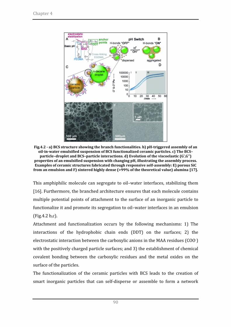
Chapter 4
90
Fig.4.2 - a) BCS structure showing the branch functionalities. b) pH-triggered assembly of an
oil-in-water emulsified suspension of BCS functionalized ceramic particles. c) The BCS–particle–droplet and BCS–particle interactions. d) Evolution of the viscoelastic (G’,G’’)
properties of an emulsified suspension with changing pH, illustrating the assembly process. Examples of ceramic structures fabricated through responsive self-assembly: E) porous SiC
from an emulsion and F) sintered highly dense (>99% of the theoretical value) alumina [17].
This amphiphilic molecule can segregate to oil–water interfaces, stabilizing them
[16]. Furthermore, the branched architecture ensures that each molecule contains
multiple potential points of attachment to the surface of an inorganic particle to
functionalize it and promote its segregation to oil–water interfaces in an emulsion
(Fig.4.2 b,c).
Attachment and functionalization occurs by the following mechanisms: 1) The
interactions of the hydrophobic chain ends (DDT) on the surfaces; 2) the
electrostatic interaction between the carboxylic anions in the MAA residues (COO-)
with the positively charged particle surfaces; and 3) the establishment of chemical
covalent bonding between the carboxylic residues and the metal oxides on the
surface of the particles.
The functionalization of the ceramic particles with BCS leads to the creation of
smart inorganic particles that can self-disperse or assemble to form a network

Preparation of β-TCP scaffolds by robocasting
91
under pH control (Fig.4.2b,c,d). The branched architecture of BCS ensures that
each molecule contains multiple potential points of attachment to the surface of
the inorganic particles, promoting also the segregation to oil–water interfaces.
The addition of a pH-switch triggers a sort of particles coagulation, which
promotes the tight packing of the ceramic particles (Fig.4.2b). When allowed to
dry, the oil phase is eliminated from our material, and we obtain this porosity as a
consequence of the oil templating.
A similar process allows the fabrication of strong materials with complex shapes
and a wide range of architectures from dense to foams with closed or open cells
[17] (Fig.4.2 e,f).
The suspensions were also emulsified with Decane (Sigma Aldrich) at 50 vol% and
stirred at 24k rpm (T25 Ultra-Turrax, IKA, Germany) in order to induce the
formation of microbubbles into the suspension, while Glucono-δ-Lactone (GdL)
(Sigma Aldrich) was finally added as pH-trigger.
The pH and rheological performance of suspensions and emulsions were analyzed
after the preparation and 72 hours after the addition of GdL.
The influence of different BCS (wt%), pH-trigger (wt%) and stirring times on the
pH, viscosity and Yield stress of the inks was evaluated according to a Design of
Experiment (DoE) approach (Face Centered Central Composite scheme (FCCCD))
(Table 4.I).
Table 4.I – Input parameters (coded levels) and output parameters of the FCCCD scheme
INPUT PARAMETERS -1 0 +1 OUTPUT PARAMETERS A BCS concentration (wt%) 2 4 8 pH
Viscosity Yield stress (Pa)
B GdL concentration (wt%/vol%) 1 2 4 C Emulsification time (min) 0 2,5 5
Regression analysis of data, contour plots and Pareto charts were obtained with
MATLAB software.
The phase composition of suspensions and emulsions was also performed before
and after sintering (Table 4.II) and the microstructure of the scaffolds was finally
analyzed by scanning electron microscopy.

Chapter 4
92
Table 4.II – Sintering treatment
Temperature (°C)
Rate increase (°C/min)
Dwell time (hours)
0-500 1 - 500 - 2
500-989 5 - 989 - 1
4.3 Results and Discussion
The suspensions exhibited basic pH (8.6-9.2) and appeared well-dispersed,
probably due to the steric and electrostatic stabilization provided by the
functionalities in the branches (EG and MAA).
Only a slight decrease of the pH was observed even quadrupling the BCS amount,
probably due to the polymer buffer properties [17] (Fig.4.3). On the other hand,
the increase in BCS reflected in the increase of the suspensions’ viscosity .
(a) (b)
Fig.4.3 – pH and viscosity of the suspensions, with increasing the amount of BCS
No statistical difference was observed among the zeta-potential of the suspensions
at different pH (titration test), probably due to the buffer property of the polymer.
Fig.4.4 – Zeta potential of the suspensions with increasing the amount of BCS

Preparation of β-TCP scaffolds by robocasting
93
The analysis of the viscoelasticity evidenced an increase of both Storage and Loss
moduli, while no Yield stress was detected (Fig.4.5).
Fig.4.5 – Viscoelastic properties of the suspensions
The loss moduli, higher than the storage moduli, confirmed the prevalent fluid
behavior of the suspensions. After the addition of GdL, a significant decrease of the
pH was observed (Fig.4.6).
Fig.4.6 – pH of the suspensions with increasing of GdL
The lowest pH were detected for the suspensions with lower amount of BCS; this is
in agreement with a previous work, in which it was stated that, because of the
buffer polymer, larger BCS concentrations lead to longer aggregation times, so
slower pH drop [17].
The addition of GdL determined also an increase of the viscosity (Fig.4.7): the
highest viscosity was exhibited by the lowest BSC suspensions. This is actually in

Chapter 4
94
agreement with the pH results (Fig.4.6), as lower pH determines higher
aggregation of the powder particles and higher viscosity.
Fig.4.7 – Viscosity of the suspensions with increasing the GdL
The rheological tests showed an increase of both Storage and Loss moduli while
increasing the GdL amount: in particular, the higher viscosity of BCS2 reflected
also in the highest G’. No yield stress was detected.
Fig.4.8 – Viscoelastic properties of the suspensions, after addition of GdL
The viscoelasticity tests were in accordance with the viscosity measurements: if
only 1wt%/vol of GdL is added, the suspensions with higher amount of BCS exhibit
higher viscosity and dynamic mechanical performance, but increasing the amount
of GdL the result is reversed (Fig.4.7-4.8).
However, it should be noted that a slight sedimentation of the powder occurred,
leading to partial solid/liquid demixing: it was hypothesized that within 72 hours
the GdL is able to induce extensive ceramic particles aggregation, by turning away
the water molecules around the particles. For that reason, the rheological tests
were partially negatively affected.

Preparation of β-TCP scaffolds by robocasting
95
After the emulsification of the suspensions with decane, the oil droplets were
stabilized by a synergetic combination of the BCS molecules in the liquid and the
functionalized particles, both of which attach to the oil–water interface.
The emulsification induced an increase of the viscosity, if compared with the
suspensions (Fig.4.9); in addition, the effect of both stirring time and BCS
concentration on the rheological performance was separately evaluated, indicating
a slight prevalence of BCS in increasing the viscosity.
Fig.4.9 – Viscosity tests of the emulsions, by varying stirring time and BCS amount
The viscoelasticity analysis of the emulsions showed also a slight increase of the
storage and loss modulus with increasing the amount of BSC (Fig.4.10), while a
higher increase of the yield stress (here approximated by the intersection between
the two curves) also occurred.
Fig.4.10 – Storage and Loss modulus of the emulsions, after 2.5 and 5 minutes of
emulsification
At high pH, both suspensions and emulsions were mainly fluid. After the addition
of GdL, a homogeneous decrease of pH occured (due to the hydrolysis of GdL to

Chapter 4
96
gluconic acid [15, 18, 19]), while increasing the viscosity (due to the formation of
multiple links between the BCS-functionalized particles).
The effect of different BCS (wt%), GdL (wt%) and stirring times on the pH,
viscosity and Yield stress of the β-TCP emulsions was assessed according to the
Design of Experiment scheme reported in Table 4.III.
Table 4.III – The full factorial FCCD scheme implemented in this study
A B C AB AC BC A2 B2 C2 pH (after 72h GdL)
Viscosity (constant shear rate 50s-1
after 96h GdL) [Pa * s]
Yield stress (after 96h GdL)
[Pa]
-1 -1 -1 1 1 1 1 1 1 5,00 4,00 4 1 -1 -1 -1 -1 1 1 1 1 6,34 5,00 5 -1 1 -1 -1 1 -1 1 1 1 4,34 12,00 56 1 1 -1 1 -1 -1 1 1 1 4,78 48,00 300 -1 -1 1 1 -1 -1 1 1 1 5,02 20,00 110 1 -1 1 -1 1 -1 1 1 1 6,14 26,00 125 -1 1 1 -1 -1 1 1 1 1 4,51 60,00 300 1 1 1 1 1 1 1 1 1 4,73 95,00 380 0 0 0 0 0 0 0 0 0 5,02 22,00 50 0 0 0 0 0 0 0 0 0 5,24 23,00 51 0 0 0 0 0 0 0 0 0 5,02 22,00 52 -1 0 0 0 0 0 1 0 0 4,55 21,00 20 1 0 0 0 0 0 1 0 0 5,01 20,00 75 0 -1 0 0 0 0 0 1 0 5,78 15,00 24 0 1 0 0 0 0 0 1 0 4,66 43,00 120 0 0 -1 0 0 0 0 0 1 4,90 5,00 35 0 0 1 0 0 0 0 0 1 4,72 32,00 250
The regression analysis of data is reported in Table 4.IV. Table 4.IV – Summary of the regression analysis of data
pH Viscosity Yield stress Coefficient p-value Coefficient p-value Coefficient p-value
Constant A B C AB AC BC A2 B2 C2
4.98 0.36 -0.52 -0.02 -0.23 -0.05 0.04 -0.12 0.32 -0.09
0.00 0.00 0.00 0.64 0.00 0.36 0.52 0.23 0.01 0.35
19.98 7.70 18.81 15.90 8.00 0.50 7.25 2.28 10.77 0.27
0.00 0.00 0.00 0.00 0.00 0.83 0.01 0.56 0.02 0.94
51.00 39.50 88.80 76.50 38.50 -18.75 12.25 -3.50 21.00 91.50
0.02 0.01 0.00 0.00 0.00 0.22 0.41 0.89 0.41 0.01
R2 R2 (adj)
96 % 92 %
95% 91%
95 % 88 %

Preparation of β-TCP scaffolds by robocasting
97
To maximize the responses, the factors with positive coefficients should be
increased and those with negative coefficients should be decreased.
Considering only the coefficients with p<0.05, the regression models for pH,
viscosity and yield stress were: Table 4.V – Regression models of the output parameters (considering p<0.05)
Output parameters Regression model
pH 2
Viscosity 2
Yield stress ( 2
On the basis of the regression analysis results, a Pareto chart was also
implemented to show the most effective input parameters on the outputs
(Fig.4.11).
Fig.4.11 – Pareto charts of the data
It was observed that the parameter which mainly affects pH, viscosity and yield
stress of the emulsions is the GdL concentration. Moreover, both the viscosity and
yield stress are secondly affected by the emulsification time, more than the BCS
concentration. As shown, the interactions among the input parameters were also
significant.
Contour plots were generated from the model equations obtained in the regression
analysis (Fig.4.12), in which the blue and red colors refer to lower and higher
values of the response, respectively.
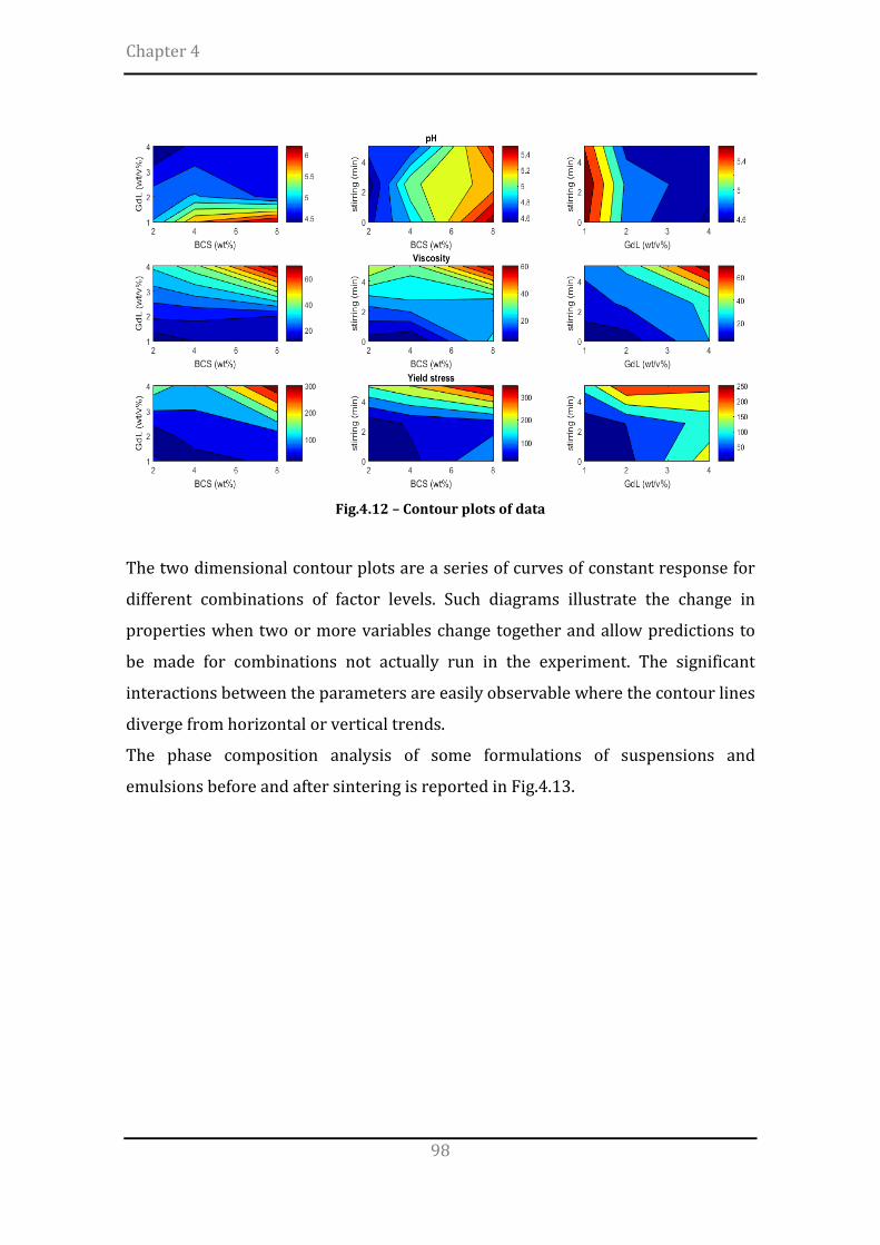
Chapter 4
98
Fig.4.12 – Contour plots of data
The two dimensional contour plots are a series of curves of constant response for
different combinations of factor levels. Such diagrams illustrate the change in
properties when two or more variables change together and allow predictions to
be made for combinations not actually run in the experiment. The significant
interactions between the parameters are easily observable where the contour lines
diverge from horizontal or vertical trends.
The phase composition analysis of some formulations of suspensions and
emulsions before and after sintering is reported in Fig.4.13.

Preparation of β-TCP scaffolds by robocasting
99
Fig.4.13 – Effect of BCS and GdL on the phase composition
Generally, the calcium phosphates solubility is strongly dependent on the pH: the
solubility increases with lowering the pH. In this respect, with increasing the GdL
amount, the dissolution of the βTCP followed the pH lowering, leading to the
formation of hydroxyapatite (HA) and brushite (CaHPO4*2H2O).
The formation of brushite was higher when lower amount of BCS was present; this
is in agreement with the pH results (Fig.4.6), as larger amount of BCS induce
slower pH drop.
Due to the difficulty in printing ink formulation with lower amount of BCS, it was
supposed that the polymer content greatly enhances the ink stability, but may also
results in larger microporosity and lower mechanical strength.
After the thermal treatment, the brushite was fully reconverted into βTCP and HA.
Due to the difficulty in printing ink formulation with lower amount of BCS, it was
supposed that the polymer content greatly enhances the ink stability, but may also
results in larger microporosity and lower mechanical strength.
The most reliable, fully injectable ink formulation for robocasting was identified as
the one containing BCS (8wt%), GdL (2wt%) and emulsified for 5 minutes
(Fig.4.14).
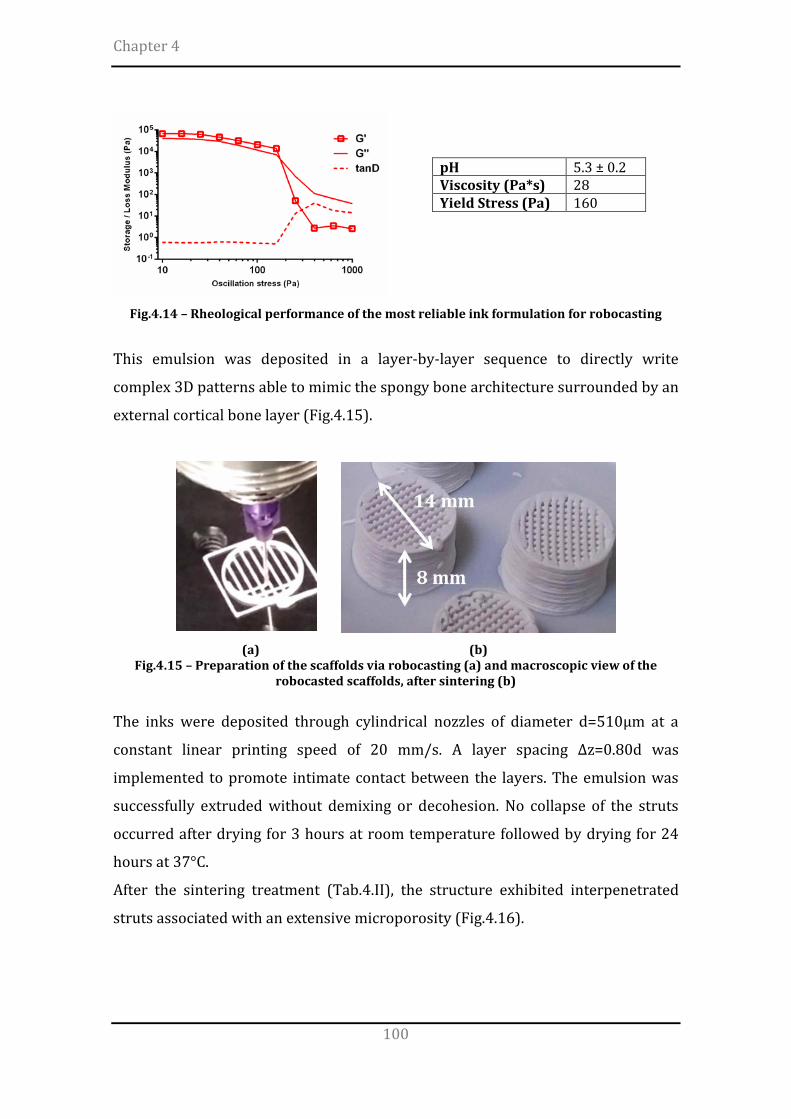
Chapter 4
100
pH 5.3 ± 0.2 Viscosity (Pa*s) 28 Yield Stress (Pa) 160
Fig.4.14 – Rheological performance of the most reliable ink formulation for robocasting
This emulsion was deposited in a layer-by-layer sequence to directly write
complex 3D patterns able to mimic the spongy bone architecture surrounded by an
external cortical bone layer (Fig.4.15).
(a) (b)
Fig.4.15 – Preparation of the scaffolds via robocasting (a) and macroscopic view of the robocasted scaffolds, after sintering (b)
The inks were deposited through cylindrical nozzles of diameter d=510µm at a
constant linear printing speed of 20 mm/s. A layer spacing ∆z=0.80d was
implemented to promote intimate contact between the layers. The emulsion was
successfully extruded without demixing or decohesion. No collapse of the struts
occurred after drying for 3 hours at room temperature followed by drying for 24
hours at 37°C.
After the sintering treatment (Tab.4.II), the structure exhibited interpenetrated
struts associated with an extensive microporosity (Fig.4.16).

Preparation of β-TCP scaffolds by robocasting
101
Fig.4.16 – Microstructure of the sintered robocasted structures
The extensive microporosity resulted from the oil templating can favour cell
attachment and proliferation, as well as the perfusion by physiological fluids [20-
22].
The mechanical performance of ceramic materials are strictly related to the
density of the green body (semifinished sample before thermal treatment), as well
as the micro- and macroporosity.
The macroporosity of the robocasted specimens was determined by geometrical
method: the relative density was determined by the ratio ρc/ρs, that is, the density
of the cellular material calculated as weight-on-volume ratio (ρc), divided by the
theoretical density of β-TCP phase (ρs=3.08 g/cm3). The porosity of the structures,
Φ, was evaluated as Φ = 1-ρc/ρs.
In addition, in order to investigate the microporosity of the struts, parallelepiped
molds were filled with the same ink formulation used for robocasting. After
appropriate drying and sintering, the porosity of the struts was evaluated by
geometrical method and the compressive strength was evaluated by uniaxial
loading of parallelepiped specimens (11 x 6 x 3 mm) with a preload of 0.5N (Table
4.VI).

Chapter 4
102
Table 4.VI – Porosity and mechanical performance of struts and robocasted samples
Total Porosity
(%)
Compressive strength
(MPa)
Young’s Modulus
(GPa)
Strut 66.7 ± 0.5 4.50 ± 0.96 0.15 ± 0.02
Robocasted 80.2 ± 0.8 1.77 ± 0.41 0.11 ± 0.02
The strength of the robocasted scaffolds is comparable with the typical values
attributed to trabecular bone [23].
Despite the optimal reproducibility and structural homogeneity of such robocasted
scaffolds, the reported mechanical performance are not actually able to meet the
requirements for load-bearing bone applications. In this respect, it can be
envisaged that the further reduction of the struts microporosity (e.g. increase of
powder content, optimization of the emulsification process) may lead to the
improvement of the final mechanical strength.
4.4 Conclusions
βTCP-based colloidal inks suitable for the preparation of 3D printed scaffolds by
robotic-assisted deposition were successfully prepared by Branched Copolymer
Surfactant (BCS) solutions, emulsification with decane and pH manipulation with
Glucono-δ-lactone (GdL). A Design of Experiment approach was implemented to
evaluate the role of BCS, GdL and stirring time on the pH, viscosity and yield stress
of the colloidal inks. It was observed that the GdL mainly affects the pH, viscosity
and yield stress of the emulsions. Some interactions among the factors were also
detected. Microporosity can play a key role in determining the biological response
to the materials, but also negatively affects the strength of the scaffold. In this
respect, further experiments are required to improve the close packing of the
powder particles, thus leading to the increase of the final mechanical performance.
A similar approach can be promising to the accurate manipulation of the
microstructure and composition of the ceramic scaffolds, allowing the fabrication
of materials with tailored features for specific applications.

Preparation of β-TCP scaffolds by robocasting
103
4.5 References
[1] Saiz E, Gremillard L, Menendez G, Miranda P, Gryn K, Tomsia AP. Preparation of porous hydroxyapatite scaffolds. Materials Science and Engineering: C. 2007;27:546-50. [2] Ben-Nissan B. Natural bioceramics: from coral to bone and beyond. Current opinion in solid state and materials science. 2003;7:283-8. [3] Bohner M, van Lenthe GH, Grunenfelder S, Hirsiger W, Evison R, Muller R. Synthesis and characterization of porous beta-tricalcium phosphate blocks. Biomaterials. 2005;26:6099-105. [4] Sous M, Bareille R, Rouais F, Clement D, Amedee J, Dupuy B, et al. Cellular biocompatibility and resistance to compression of macroporous beta-tricalcium phosphate ceramics. Biomaterials. 1998;19:2147-53. [5] Deville S, Saiz E, Tomsia AP. Freeze casting of hydroxyapatite scaffolds for bone tissue engineering. Biomaterials. 2006;27:5480-9. [6] Leong KF, Cheah CM, Chua CK. Solid freeform fabrication of three-dimensional scaffolds for engineering replacement tissues and organs. Biomaterials. 2003;24:2363-78. [7] Bose S, Vahabzadeh S, Bandyopadhyay A. Bone tissue engineering using 3D printing. Materials Today. 2013;16:496-504. [8] Sachs EM, Haggerty JS, Cima MJ, Williams PA. Three-dimensional printing techniques. Google Patents; 1993. [9] Hollister SJ. Porous scaffold design for tissue engineering. Nature materials. 2005;4:518-24. [10] Wegst UG, Bai H, Saiz E, Tomsia AP, Ritchie RO. Bioinspired structural materials. Nature materials. 2015;14:23-36. [11] Smay JE, Cesarano J, Lewis JA. Colloidal inks for directed assembly of 3-D periodic structures. Langmuir. 2002;26. [12] Miranda P, Pajares A, Saiz E, Tomsia AP, Guiberteau F. Mechanical properties of calcium phosphate scaffolds fabricated by robocasting. J Biomed Mater Res A. 2008;85:218-27. [13] Warnke PH, Seitz H, Warnke F, Becker ST, Sivananthan S, Sherry E, et al. Ceramic scaffolds produced by computer-assisted 3D printing and sintering: characterization and biocompatibility investigations. J Biomed Mater Res B Appl Biomater. 2010;93:212-7. [14] Weaver JVM, Rannard SP, Cooper AI. Polymer-Mediated Hierarchical and Reversible Emulsion Droplet Assembly. Angewandte Chemie-International Edition. 2009;48:2131-4. [15] Woodward RT, Chen L, Adams DJ, Weaver JVM. Fabrication of large volume, macroscopically defined and responsive engineered emulsions using a homogeneous pH-trigger. Journal of Materials Chemistry. 2010;20:5228-34. [16] Woodward RT, Weaver JVM. The role of responsive branched copolymer composition in controlling pH-triggered aggregation of "engineered'' emulsion droplets: towards selective droplet assembly. Polymer Chemistry. 2011;2:403-10. [17] Garcia-Tunon E, Barg S, Bell R, Weaver JVM, Walter C, Goyos L, et al. Designing Smart Particles for the Assembly of Complex Macroscopic Structures. Angewandte Chemie-International Edition. 2013;52:7805-8.
Chapter 4
104
[18] Pocker Y, Green E. Hydrolysis of D-Glucono-Delta-Lactone .1. General Acid-Base Catalysis, Solvent Deuterium-Isotope Effects, and Transition-State Characterization. Journal of the American Chemical Society. 1973;95:113-9. [19] Pocker Y, Green E. Hydrolysis of D-Glucono-Delta-Lactone .2. Comparative Studies of General Acid-Base Catalyzed-Hydrolysis of Methylated Derivatives. Journal of the American Chemical Society. 1974;96:166-73. [20] Andrade JC, Camilli JA, Kawachi EY, Bertran CA. Behavior of dense and porous hydroxyapatite implants and tissue response in rat femoral defects. J Biomed Mater Res. 2002;62:30-6. [21] He X, Su B, Tang ZH, Zhao B, Wang XY, Yang GZ, et al. The comparison of macroporous ceramics fabricated through the protein direct foaming and sponge replica methods. Journal of Porous Materials. 2012;19:761-6. [22] Hyers R, SanSoucie M. Porous calcium phosphate networks for synthetic bone material. Google Patents; 2010. [23] Misch CE, Qu Z, Bidez MW. Mechanical properties of trabecular bone in the human mandible: implications for dental implant treatment planning and surgical placement. Journal of oral and maxillofacial surgery : official journal of the American Association of Oral and Maxillofacial Surgeons. 1999;57:700-6; discussion 6-8.

105
The calcium phosphate bone cements (CPCs) have been widely studied in the last
decades as injectable materials for minimally invasive surgery to assist the
regeneration of bone. In this chapter, the preparation of a novel Sr-doped apatitic
formulation is reported: Sr-substituted αTCP phases, designed to be the unique
cement inorganic precursors, were prepared and mixed with appropriate amount
of sodium alginate solutions.
A chemico-physical, morphological, mechanical and biological characterization was
carried out on the formulation complying with the clinical requirements, in
comparison with a polymer-free commercial CPC. The effect of chemical
composition and some processing parameters on the setting times and
compressive strength of Sr-containing apatitic bone cements was also investigated
according to a Design of Experiment approach.
5.1 Preparation of Sr-doped Calcium Phosphate bone cements (CPCs)
In the development of CPCs, the method based on the hydrolysis and
transformation of α-Ca3(PO4)2 (αTCP) into elongated calcium-deficient
hydroxyapatite (CD-HA) particles is particularly interesting and promising [1].
However, due to critical synthesis conditions, commercial α-TCP, reagent or
biomedical grade, are very scarce. This forces researchers and developers to
synthesize it themselves.
It is well documented that some ionic substitutions may exert a drastic effect on
the thermodynamic relationships between α- and β-TCP [2]. For example, partial
Chapter 5 DEVELOPMENT OF APATITIC
BONE CEMENTS

Chapter 5
106
substitution of Mg for Ca in TCP increases the thermal stability of the β-phase and
gives rise to a binary phase field where β + α-TCP solid solutions coexist [3].
In the same way, partial substitutions of Zn and Sr ions for Ca have a similar effect
to Mg [4]. In order to locally evoke a specific cellular response based on the cell–
material interaction, nowadays the research on bone cements is focused on the
synthesis of ion-doped calcium phosphate cements able to transform into ion-
doped apatite upon injection.
Among the various ions, strontium has been proposed to possess both a bone
formation stimulating and at the same time anti-resorptive effect and is thus used
in systemic osteoporosis therapy [5] (Fig.5.1).
Fig.5.1 - Effects of Sr2+ ions on bone metabolism: stimulation of osteoblastprecursor proliferation and osteogenic differentiation (1), increase of bone mineralization by
osteoblasts (2), reduced osteoclast-precursor recruitment and osteoclastogenesis (3), decreased resorption activity and increased apoptosis of mature osteoclasts (4) as well as
interaction with the osteoblast/osteoclast paracrine signalling (5) [6].
5.1.1 Synthesis and characterization of Sr-αTCP phases
Sr-substituted α-TCP powders with different strontium content (i.e. Sr/(Ca+Sr) = 0,
2, 5, 10 mol%, henceforth coded as Sr0, Sr2, Sr5 respectively) were synthesized by
solid state reaction of stoichiometric amounts of calcium carbonate (CaCO3, Carlo
Erba, Italy), calcium hydrogen phosphate (CaHPO4, Sigma Aldrich) and strontium
carbonate (SrCO3, Carlo Erba, Italy) [7, 8], following the reaction:

Development of apatitic bone cements
107
During the thermal treatment, the decomposition of the initial reactants occurs,
according to:
CaCO3 CaO + CO2
2CaHPO4 Ca2P2O7 + H2O + CO2
Ca2P2O7 + CaO Ca3(PO4)2
The powders were firstly dry mixed for 30 minutes, then uniaxially pressed to
form pellets, and finally treated at 1400 °C for 1 hour (Fig.5.2).
Fig.5.2 – FCN Furnace with mobile crucible (Nannetti, Faenza, Italy)
After the firing, the pellet was removed from the hot furnace and placed in a large
pan where it was rapidly crushed with a pestle within a few seconds. Then, the
final product was ground, sieved under 150µm and further milled by planetary
mono mill (Pulverisette 6 classic line, Fritsch, Germany) (Fig.5.3).
(a) (b)
Fig.5.3 – Planetary mono mill Pulverisette 6 classic line, Fritsch, Germany (a); schematic diagram of the planetary ball mill and the jar (b)

Chapter 5
108
The planetary ball mill owes its name to the planet-like movement of its vial (s)
(Fig.5.3). Since the vials and the supporting disc rotate in opposite directions, the
centrifugal forces alternatively act in like and opposite directions. This causes the
milling balls to run down the inside wall of the vial – the friction effect, followed by
the material being milled and milling balls lifting by of and travelling freely
through the inner chamber of the vial and colliding against the opposite inside wall
[9].
The transfer of mechanical energy to the powder particles results in introduction
of strain into the powder through generation of dislocations and other defects
which act as fast diffusion paths. Additionally, refinement of particle and grain
sizes occurs, and consequently the diffusion distances are reduced. Further, a slight
rise in powder temperature occurs during milling.
The powders were dispersed in pure ethanol, to inhibit αTCP transitions to
hydrated phases, while preserving the heating of the material during milling. The
powders were milled for 50 minutes at 400 rpm using a zirconia jar with 5 mm
diameter grinding media (ball-to-powder weight ratio = 2).
5.1.2 Synthesis of aqueous setting solutions
In this work, aqueous solutions containing 5%wt of Na2HPO4 (Sigma Aldrich),
enriched with 2 wt% of sodium alginate (Alginic Acid Sodium Salt from Brown
Algae, Sigma Aldrich) were prepared and mixed with the powders to obtain the
cements.
5.1.3 Liquid-On-Powder Ratio And Mixing Procedure
The microstructure and porosity of CPCs can be tuned by adjusting some
processing parameters, such as the particle size of the powder phase and the
liquid-on-powder ratio (L/P). The reactivity of the powder increases when
decreasing its particle size, due to an increase in its specific surface area [10]. This
results in a higher supersaturation degree achieved in the cement paste, which
favors crystal nucleation and results in the precipitation of more numerous and
smaller needle-like crystals, instead of the larger plate-like crystals formed when

Development of apatitic bone cements
109
big particles are used. These different microstructures give rise to different pore
size distributions in the set cements (Fig.5.4).
Fig.5.4 – Effect of particle size and liquid-on-powder ratio on the CPC microstructure [10]
For the same L/P ratio and different powder size, the total porosity of the cement
remains constant, but smaller pores are formed in the fine cement (i.e. using small
particles). Another way of tuning the porosity and the pore size distribution of the
CPCs is by varying the L/P ratio. At low L/P ratios the space between particles in
the blend decreases. Considering that the precipitation of HA crystals takes place
surrounding the initial powder particles, this leads to a more compact structure of
crystal agglomerates. In contrast, when the L/P ratio increases, the total porosity
of the cements increases and larger pores are formed due to the augmented
separation between aggregates resulting from the larger distance between the
original α-TCP particles.
In this work, a formulation able to meet the clinical requirements in terms of
setting times was prepared with L/P=0.48 and a robust characterization was
performed in comparison with a commercial polymer-free CPC (KyphOs FS™,
Medtronic Spine LLC, Minneapolis, MN, USA) [1]. The investigation of chemical
composition and some powder milling parameters on the setting times and
compressive strength of the cements was also carried out with L/P=0.55, to ensure
the complete injectability of cements with different particle size precursors.
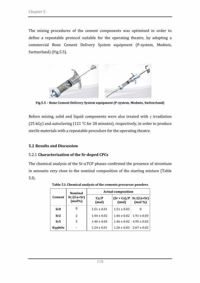
Chapter 5
110
The mixing procedures of the cement components was optimized in order to
define a repeatable protocol suitable for the operating theatre, by adopting a
commercial Bone Cement Delivery System equipment (P-system, Medmix,
Switzerland) (Fig.5.5).
Fig.5.5 – Bone Cement Delivery System equipment (P-system, Medmix, Switzerland)
Before mixing, solid and liquid components were also treated with γ irradiation
(25 kGy) and autoclaving (121 °C for 20 minutes), respectively, in order to produce
sterile materials with a repeatable procedure for the operating theatre.
5.2 Results and Discussion
5.2.1 Characterization of the Sr-doped CPCs
The chemical analysis of the Sr-αTCP phases confirmed the presence of strontium
in amounts very close to the nominal composition of the starting mixture (Table
5.I). Table 5.I. Chemical analysis of the cements precursor powders
Cement Nominal
Sr/(Ca+Sr) (mol%)
Actual composition
Ca/P (mol)
(Sr + Ca)/P (mol)
Sr/(Ca+Sr) (mol %)
Sr0 0 1.51 ± 0.01 1.51 ± 0.03 0
Sr2 2 1.44 ± 0.02 1.46 ± 0.02 1.91 ± 0.03
Sr5 5 1.40 ± 0.03 1.46 ± 0.02 4.95 ± 0.02
KyphOs - 1.24 ± 0.01 1.26 ± 0.03 2.67 ± 0.02

Development of apatitic bone cements
111
The phase composition and the lattice parameters of the precursor powders were
investigated by X-ray diffraction patterns, evidencing peaks mainly ascribed to α-
TCP and β-TCP phases (Fig.5.6).
Fig.5.6 – XRD patterns of the cement precursor powders. Peaks legend: Sr-αTCP (•), Sr-βTCP
(□), HA (x), SrCO3 (*), Mg3(PO4)2 (○), MgHPO4 (+)
The Sr-doped powders prepared in this work exhibited only a slight increase in the
amount of βTCP phase with increasing the strontium content (estimated between
8wt% and 12wt%). Conversely, the KyphOs cement also contained SrCO3,
Mg3(PO4)2 and MgHPO4 phases, as reported in [1].
The formation of Sr-αTCP precursors upon solid state synthesis at high
temperature and subsequent fast cooling was accompanied by crystallization of
the βTCP polymorph, thermodynamically stable below 1125 °C [11, 12], especially
due to the presence of strontium, which has a recognized ability to promote the
βTCP formation [3, 13]. However, in spite βTCP did not take active part to the
setting mechanisms, its presence in small amounts did not hamper significantly the
setting properties of the cement, thus successfully achieving setting times
compliant with the requirements relevant for the clinical practice.
The phase composition and the lattice parameters of the cements, obtained after 7
days of immersion in Hanks’ balanced salt solution (H6648, Sigma Aldrich) at 37°C,
were investigated by Bruker D8 Advance.

Chapter 5
112
The diffraction patterns of the cements evidenced the complete transformation of
αTCP into nanocrystalline HA (Fig. 5.7) after 7 days of soaking, while βTCP content
remained unchanged.
Fig.5.7 – XRD patterns of the hardened cements, 7 days after soaking.
Peaks legend: Sr-αTCP (•), Sr-βTCP (□), HA (x), SrCO3 (*), Mg3(PO4)2 (○), MgHPO4 (+)
A slight and continuous peaks shift towards higher d values was also detected with
increasing the Sr amount. The control cement exhibited SrCO3, Mg3(PO4)2 and
MgHPO4 phases in addition to αTCP and βTCP, as reported elsewhere [1]. The
cements developed in this work underwent complete transformation of αTCP into
HA after 7 days of soaking, whereas the control cement still exhibited peaks
belonging to the precursor phases, thus indicating incomplete transformation
(Fig.5.6).
The injectability of the cements was qualitatively evaluated by measuring the
amount of cement in the syringe after extrusion, according to [14]. The initial and
final setting times of the cements (henceforth indicated as Tin and Tfin,
respectively) were evaluated by using Gillmore apparatus (Fig.5.8), according to
ASTM C266-99, testing 5 specimens for each composition, upon immersion in
Hanks’ solution at 37 °C.

Development of apatitic bone cements
113
Fig.5.8 – Gillmore apparatus to measure the setting times of cements
The cements showed complete injectability after extrusion through 13 Gauges
needles, i.e. the totality of the paste could be extruded from the syringe without de-
mixing; it was also found that the setting times were strongly influenced by the
amount of incorporated strontium (Table 5.II).
Table 5.II. Initial and final setting times of the cements.
Cement Tin (minutes)
Tfin (minutes)
Sr0 9 ± 2 14 ± 2
Sr2 11 ± 2 22 ± 3
Sr5 29 ± 4 47 ± 5
KyphOs 12 ± 2 23 ± 1
The average domain size of the crystalline phases was 270 ± 40 nm for αTCP and
75 ± 15 nm for βTCP. No significant variations of the domain size of TCP
polymorphs in function of the Sr content was detected. In the HA phase the peak
width of (300) and (002) reflections (d ≅ 2.72 and 3.44 Å, respectively) were
separately evaluated, thus achieving the size of coherent domains along both the
ab plane and the c axis. It was found that the introduction of strontium induce a
slight increase of the domain sizes (Fig.5.9a) and cell volume (Fig.5.9b), associated
also with slight crystal deformation (Fig. 5.9c).

Chapter 5
114
Fig.5.9 - a) Size of the coherent domain of the HA lattice along the (002) and (300) directions;
b) cell volume of HA phase in Sr-HA cements; c) c/a ratio vs. Sr content in Sr-HA cements.
In respect to the effect of strontium doping, a retard in the setting behaviour has
been observed (Tab.3), thus confirming the actual substitution in the HA lattice, as
also previously observed by [6, 15]. Strontium substitution in the HA lattice was
also confirmed by the increase of cell volume, highlighted by the general shift of
XRD peaks towards higher d values with increasing the Sr amount, due to the
larger ionic radius of strontium, if compared with calcium (Sr2+ ionic radius =
0.113 nm; Ca2+ ionic radius = 0.099 nm) [8]. Besides, the introduction of strontium
ions provoked a slight deformation of the HA lattice, thus resulting in anisotropic
crystal growth along the c axis, as highlighted by the progressive increase of c/a
with the strontium content (Fig.5.9c), whereas the general domain size was not
significantly affected by the strontium concentration in the calcium crystals sites,
at least up to 5 mol% (Fig.5.8a). This finding further supports the actual Sr-
substitution in the HA lattice, as also evidenced by [16].
Then, the biocompatibility of the cements was preliminarily assessed in
collaboration with the biologists of ISTEC-CNR. In this respect, human osteoblast-
like cell line, MG63 cell line, purchased from Lonza (Italy) were cultured in
Dulbecco Modified Eagle’s (DMEM)/F12 Medium (Gibco), containing penicillin-
streptomycin (100 U/ml-100 µg/ml) supplemented with 10% foetal bovine serum
(FBS) and kept at 37°C in an atmosphere of 5% CO2. For the experiments, cells
were plated at 1.5×10⁴/cm2 and cultured for up to 3 days. Cement discs were
sterilized with 3 washes in ethanol 70 % for 20 min followed by 3 washes in PBS
1X for 10 min each. Samples were then air dried and sterilized by UV irradiation
for 30 min per side under laminar flow hood and preconditioned for three days in
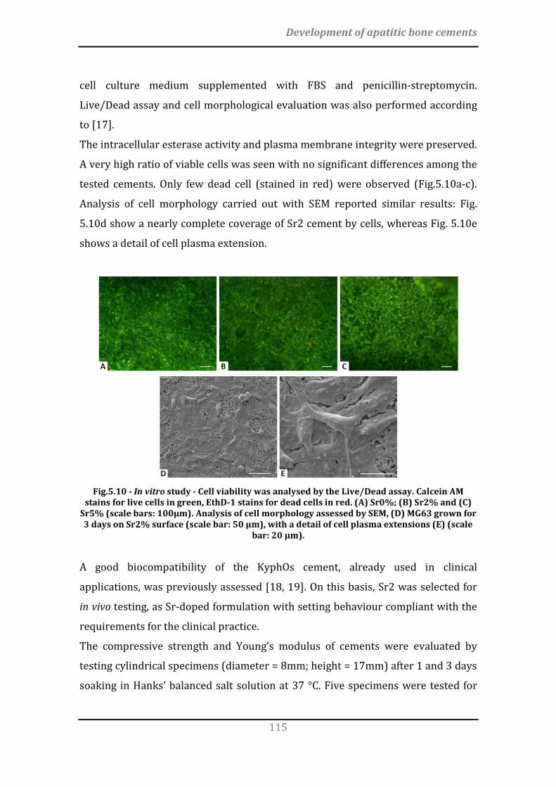
Development of apatitic bone cements
115
cell culture medium supplemented with FBS and penicillin-streptomycin.
Live/Dead assay and cell morphological evaluation was also performed according
to [17].
The intracellular esterase activity and plasma membrane integrity were preserved.
A very high ratio of viable cells was seen with no significant differences among the
tested cements. Only few dead cell (stained in red) were observed (Fig.5.10a-c).
Analysis of cell morphology carried out with SEM reported similar results: Fig.
5.10d show a nearly complete coverage of Sr2 cement by cells, whereas Fig. 5.10e
shows a detail of cell plasma extension.
Fig.5.10 - In vitro study - Cell viability was analysed by the Live/Dead assay. Calcein AM
stains for live cells in green, EthD-1 stains for dead cells in red. (A) Sr0%; (B) Sr2% and (C) Sr5% (scale bars: 100µm). Analysis of cell morphology assessed by SEM, (D) MG63 grown for 3 days on Sr2% surface (scale bar: 50 µm), with a detail of cell plasma extensions (E) (scale
bar: 20 µm).
A good biocompatibility of the KyphOs cement, already used in clinical
applications, was previously assessed [18, 19]. On this basis, Sr2 was selected for
in vivo testing, as Sr-doped formulation with setting behaviour compliant with the
requirements for the clinical practice.
The compressive strength and Young’s modulus of cements were evaluated by
testing cylindrical specimens (diameter = 8mm; height = 17mm) after 1 and 3 days
soaking in Hanks’ balanced salt solution at 37 °C. Five specimens were tested for

Chapter 5
116
each cement and timepoint by using a universal testing machine (MTS Insight 5,
Minnesota, USA) with a crosshead speed of 0.5 mm/min. The Young’s modulus was
approximated by calculating the slope of the linear, elastic portion of the stress–
strain curves. The porosity percentage was evaluated on the cylindrical specimens
immersed in Hanks’ balanced salt solution at 37°C for 3 days, as P=1-ρ/ρ0, where ρ
is the cement density calculated as weight-on-volume ratio and ρ0 is the theoretical
density of the hydroxyapatite phase (3.16 g/cm3).
As setting times shorter than 30 minutes are usually required for clinical
applications, [20, 21] only Sr0 and Sr2, in comparison with KyphOs, were
mechanically tested (see Table 2) on cylindrical specimens (diameter=9mm,
height=17mm).
The KyphOs cement exhibited significantly higher compressive strength and
Young’s modulus than Sr0 and Sr2 (Fig.5.11).
Fig.5.11 - Evaluation of compressive strength of the studied cements
In this respect, the estimated Young’s modulus after 3 days were EKYPHOS=3.6±0.5
GPa, ESr0=2.3±0.7 GPa and ESr2=2.6±0.4 GPa. Sr0 and Sr2 cements exhibited a
porosity extent of ∼48%, resulting significantly higher than KyphOs (∼31%).
The setting of apatite cements is mainly based on the physical interlocking of
nanosized CD-HA crystals that heterogeneously nucleate and grow on the surface
of αTCP grains, with typical flaky- to needle-like morphology and open micron-
sized porosity [8, 10, 22, 23]. In the present work such microstructures were
observed for the new cements, without significant differences induced by the

Development of apatitic bone cements
117
introduction of strontium (Fig.5.12). Conversely, KyphOs exhibited a more close-
packed microstructure without evidence of elongated particles.
Fig.5.12 – Microstructure of the cements after 7 days of immersion at 37 °C in Hank’s
Balanced solution. a) Sr0, b) Sr2; c) KyphOs. Scale bar = 500nm Conversely, KyphOs exhibited a more close-packed microstructure without
evidence of elongated particles.
In this respect, considering that no effects related to different amounts of
strontium can be addressed (Table 1), it can be supposed that the difference in the
cement microstructure is ascribable to the incomplete transformation of KyphOs
precursor.
The in vivo performance of the Sr2 and KyphOs cements were evaluated by
surgeons of Policlinico Gemelli – Università Cattolica Sacro Cuore (Roma) after
implantation of Sr2 and KyphOs in 3 New Zealand White (NZW) male rabbits
(weighing about 3 Kg) for each cement. The tests were conducted with previous
approval of the institutional Ethical Committee strictly following Italian (Law by
Decree, 27 January 1992, No.116), European (Directive 86/609/EEC) and
International Laws and Regulations (ISO 10993-2-Animal Welfare Requirements).
The cements were implanted according to a previously reported procedure [24-
26]. Briefly, a blind tunnel (diameter = 4 mm; length = 8 mm) was firstly
aseptically created under fluoroscopic control by a surgical drill in the
metaepiphyseal distal zone of both femurs, then irrigated with a saline solution
and filled by injection with the cements. All the procedures were performed under
general anaesthesia.
At 4 weeks after surgery, the animals were pharmacologically euthanized with
intravenous administration of Tanax, under general anaesthesia. The femurs were

Chapter 5
118
then harvested and all surrounding soft-tissue was removed. The presence of
deformities or fractures and the bone-cement interface were investigated. For
histological analysis, the harvested specimens were fixed in phosphate-buffered
4% paraformaldehyde and stored at 4° C for 12 hours until processing. Then, the
specimens were embedded in Technovit 7200, according to the manufacturers
protocol (Exakt, Germany). Using a saw microtome (Leica Microsystems Srl, Italy),
three consecutive central sections (30 ± 10 µm) were cut and stained with
toluidine blue. The region of interest (ROI) was made by tracing over the material
followed by a 100 pixels increase to include the bone-cement interface.
The microscopic examination was performed by an optical microscope (Carl Zeiss
Axioscop 40 equipped with Axiocam ICC 3 Zeiss) and Axiovision 4.8 software.
Standard terms and nomenclature for bone histomorphometric analysis were
used, according to [27] (Table 5.III). Table 5.III – Terms and nomenclature for histomorphometric analysis
Parameter Abbreviation Formula Material Perimeter M-Pm Bone Material Contact Length BMC-Le Bone Pores Length BPo-Le Material Diameter M-Dm Bone Material Contact Rate BMCR (BMC-Le / M-Pm) x 100 Bone Penetration Rate Length BPR-Le (BPo-Le / (M-Dm/2)) x100
The histological analysis of the explants at 4 weeks after the injection in vivo
evidenced a positive interaction of both cements with the surrounding bone tissue,
without signs of inflammatory processes, fractures or infections. The penetration
of bone tissue was more evident for Sr2 cement (Fig.5.12 a,c). The histological
analysis showed enhanced deposition of new bone around Sr2 cement, if
compared with KyphOs (Fig.5.13 b,d).
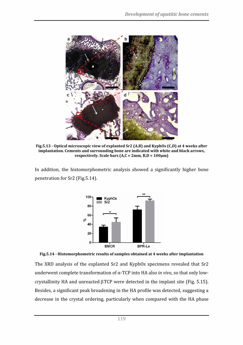
Development of apatitic bone cements
119
Fig.5.13 - Optical microscopic view of explanted Sr2 (A,B) and KyphOs (C,D) at 4 weeks after
implantation. Cements and surrounding bone are indicated with white and black arrows, respectively. Scale bars (A,C = 2mm, B,D = 100µm)
In addition, the histomorphometric analysis showed a significantly higher bone
penetration for Sr2 (Fig.5.14).
Fig.5.14 - Histomorphometric results of samples obtained at 4 weeks after implantation
The XRD analysis of the explanted Sr2 and KyphOs specimens revealed that Sr2
underwent complete transformation of α-TCP into HA also in vivo, so that only low-
crystallinity HA and unreacted βTCP were detected in the implant site (Fig. 5.15).
Besides, a significant peak broadening in the HA profile was detected, suggesting a
decrease in the crystal ordering, particularly when compared with the HA phase
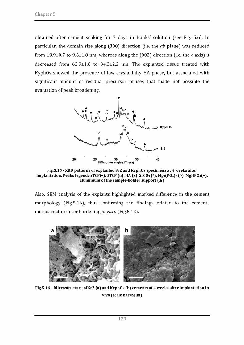
Chapter 5
120
obtained after cement soaking for 7 days in Hanks’ solution (see Fig. 5.6). In
particular, the domain size along (300) direction (i.e. the ab plane) was reduced
from 19.9±0.7 to 9.6±1.8 nm, whereas along the (002) direction (i.e. the c axis) it
decreased from 62.9±1.6 to 34.3±2.2 nm. The explanted tissue treated with
KyphOs showed the presence of low-crystallinity HA phase, but associated with
significant amount of residual precursor phases that made not possible the
evaluation of peak broadening.
Fig.5.15 - XRD patterns of explanted Sr2 and KyphOs specimens at 4 weeks after
implantation. Peaks legend: αTCP(•), βTCP (□), HA (x), SrCO3 (*), Mg3(PO4)2 (○), MgHPO4(+), aluminium of the sample-holder support (▲)
Also, SEM analysis of the explants highlighted marked difference in the cement
morphology (Fig.5.16), thus confirming the findings related to the cements
microstructure after hardening in vitro (Fig.5.12).
Fig.5.16 – Microstructure of Sr2 (a) and KyphOs (b) cements at 4 weeks after implantation in
vivo (scale bar=5µm)

Development of apatitic bone cements
121
The different morphology of Sr2 and control cement after hardening in vitro was
confirmed by compositional and morphological analysis of the tissue explants after
4 weeks in vivo (Fig.5.13 and 5.14). In this respect, complete transformation of
αTCP into HA was detected for Sr2 (Fig.5.7), associated with a more extensive
microporosity (Fig.5.12). It can be hypothesized that the more extensive
transformation of the cement precursors in needle-like HA crystals and the
presence of a bio-erodible polymer such as alginate, have played a key role in the
occurrence of discontinuities within the Sr2 cement in vivo, leading to an enhanced
penetration of bone tissue, if compared with KyphOs (Fig.5.13 and 5.14).
It can be also hypothesized that the multi-phase composition of the KyphOs
precursor may have hampered extensive transformation into HA, thus maintaining
a more compact microstructure and a reduced porosity, while exhibiting a
significantly higher compressive strength (Fig.5.11). However, such features
significantly impacted on new bone penetration, possibly limiting the
osteointegration of the control cement in the surrounding bone.
In the pursuing of bone regeneration, it is well accepted that the rapid formation of
a tight bone-cement interface associated with bone penetration is a main goal [28-
30], as well as to prevent the formation of fibrous or necrotic areas into the bone
defects [31]. Therefore, in spite of a reduced strength, even though acceptable for
many clinical applications [32], the development of bone cements with open,
porous microstructure can be considered as a major goal that, particularly in the
long term, can result into improved bone healing and recovery of mechanical
functionality. In this respect, deeper investigation are required, particularly with
longer term in vivo assessment, to clarify this assumption and to ascertain the
potential of effective bio-resorption.
It can be also observed that the use of single-phase precursors permits the easy
tailoring of the amount of strontium introduced in the cement, while improving the
osteointegration of the material with the surrounding bone. A further optimization
of the rheological properties may open to the development of a platform of
bioactive injectable materials with tailored composition and viscosity, with
perspective of wide applications in different anatomical compartments such as

Chapter 5
122
vertebral bodies, tibial plateau, proximal humerus, wrist and calcaneus [33] as well
as the hip and femoral neck [34].
5.2.2 Designing the performance of CPCs
The effect of the strontium amount as well as milling time and milling media
diameter on the powder particle size, as well as setting times and compressive
strength of Sr-containing apatitic bone cements was investigated according to a
Design of Experiment (DoE) approach.
A face-centered composite design was used, and the set of experiment reported in
Table 5.IV was implemented.
Table 5.IV – Design matrix for the experimental design validation conditions and responses.
Random order A B C D50
(µm) Tin
(min) Tfin
(min)
5 -1 -1 -1 2.3 13 ± 1 20 ± 1 9 1 -1 -1 2.2 27 ± 2 58 ± 3
10 -1 1 -1 1.5 12 ± 1 18 ± 2 19 1 1 -1 1.4 25 ± 2 56 ± 3
2 -1 -1 1 4.1 18 ± 3 30 ± 2 6 1 -1 1 4.3 35 ± 2 74 ± 3
13 -1 1 1 2.2 16 ± 2 27 ± 2 7 1 1 1 2.1 34 ± 2 71 ± 4
15 0 0 0 2.5 21 ± 2 38 ± 1 17 0 0 0 2.3 22 ± 1 41 ± 3
3 0 0 0 2.4 20 ± 2 40 ± 4 12 0 0 0 2.5 19 ± 2 40 ± 2 18 0 0 0 2.3 20 ± 2 40 ± 3 14 -1 0 0 2.7 15 ± 2 23 ± 2
8 1 0 0 2.6 26 ± 2 62 ± 3 4 0 -1 0 3.1 21 ± 3 48 ± 2
16 0 1 0 1.9 19 ± 1 45 ± 2 11 0 0 -1 1.8 16 ± 2 41 ± 2
1 0 0 1 3.1 23 ± 3 51 ± 2
The planetary ball milling parameters adopted in this activity caused an extensive
powder comminution, as showed by the low values of D50, if compared with other
works [35, 36].

Development of apatitic bone cements
123
During a planetary ball milling treatment, the reduction in powder size and crystal
order occured by high-energy ball-ball and ball-wall impacts [37, 38], thus leading
to highly reactive powders upon mixing with aqueous solutions [39, 40].
The regression analysis of data is reported in Table 5.V. To maximize the
responses, the factors with positive coefficients should be increased and those
with negative coefficients should be decreased.
Table 5.V. Results of the regression analysis of data
D50 Tin Tfin Coefficient p-value Coefficient p-value Coefficient p-value
Constant A B C AB AC BC A2 B2 C2
2.45 -0.02 -0.69 0.66 -0.04 0.04 -0.31 0.14 -0.01 -0.01
0.00 0.61 0.00 0.00 0.39 0.38 0.00 0.06 0.92 0.41
19.86 7.31 -0.80 3.30 0.00 1.00 0.00 1.32 0.82 0.32
0.00 0.00 0.11 0.00 0.99 0.06 0.98 0.16 0.37 0.72
41.64 20.31 -1.30 6.00 0.00 1.50 -0.25 -1.44 2.56 2.06
0.00 0.00 0.15 0.00 0.99 0.09 0.79 0.38 0.14 0.22
As shown, the response were significantly influenced by both the factors and their
interactions. Considering the coefficients with p<0.10, the regression equation for
D50, Tin and Tfin are shown in the following equations:
D50 = 2.45 – 0.69B + 0.66C – 0.31BC + 0.14 A2
Tin = 19.86 + 7.31A + 3.3C + AC
Tfin = 41.64 + 20.31A + 6C + AC
These equations reflect the quantitative influence of the processing variables. The
R2 values indicate the percentage of the variation in the response that can be
explained by varying the factors [41, 42].
The statistical analysis for the response showed that the standard error of estimate
was 0.11 for D50, 1.43 for Tin and 2.21 for Tfin. The R2 values for the observed
responses were 0.96, 0.94 and 0.95 for D50, Tin and Tfin, respectively, while the

Chapter 5
124
respective Q2 values were 0.92, 0.88 and 0.91, thus exhibiting a very good fitting
quality of the models.
It was observed that a decrease in D50 was mainly achieved by increasing the
milling time and decreasing the milling media diameter, probably due to the higher
surface area exposed by the spheres [9, 43, 44]. A significant reduction in setting
times was obtained by reducing the strontium content and milling media diameter,
more than prolonging the milling time (Fig.5.17). A quadratic relationship of the
strontium content on D50 was also detected.
Fig.5.17 - Pareto charts evaluating the effect of experimental parameters on D50, Tin and Tfin
To investigate the response of the system for combinations not actually run in the
experiment, 2D contour plots were also generated (Fig.5.18).
Fig.5.18 - Contour plots for the effects of strontium content, milling time and milling media
diameter on the D50 (top row), initial setting time (middle row) and final setting time (bottom row).
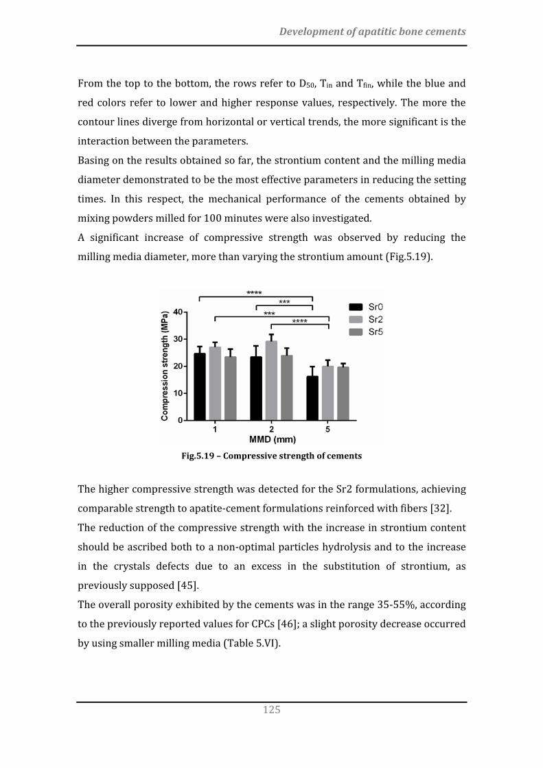
Development of apatitic bone cements
125
From the top to the bottom, the rows refer to D50, Tin and Tfin, while the blue and
red colors refer to lower and higher response values, respectively. The more the
contour lines diverge from horizontal or vertical trends, the more significant is the
interaction between the parameters.
Basing on the results obtained so far, the strontium content and the milling media
diameter demonstrated to be the most effective parameters in reducing the setting
times. In this respect, the mechanical performance of the cements obtained by
mixing powders milled for 100 minutes were also investigated.
A significant increase of compressive strength was observed by reducing the
milling media diameter, more than varying the strontium amount (Fig.5.19).
Fig.5.19 – Compressive strength of cements
The higher compressive strength was detected for the Sr2 formulations, achieving
comparable strength to apatite-cement formulations reinforced with fibers [32].
The reduction of the compressive strength with the increase in strontium content
should be ascribed both to a non-optimal particles hydrolysis and to the increase
in the crystals defects due to an excess in the substitution of strontium, as
previously supposed [45].
The overall porosity exhibited by the cements was in the range 35-55%, according
to the previously reported values for CPCs [46]; a slight porosity decrease occurred
by using smaller milling media (Table 5.VI).

Chapter 5
126
Table 5.VI – Porosity and Young’s modulus of cements with different strontium amounts and milling media diameter
Porosity (%) Young’s modulus (GPa) MMD (mm) MMD (mm)
1 2 5 1 2 5 Sr0 45 ± 2 46 ± 3 53 ± 2 2.2 ± 0.3 2.3 ± 0.2 1.8 ± 0.6 Sr2 44 ± 1 42 ± 2 46 ± 2 2.1 ± 0.3 2.3 ± 0.4 2.0 ± 0.7 Sr5 44 ± 2 47 ± 2 49 ± 1 1.9 ± 0.2 1.8 ± 0.4 1.7 ± 0.4
A flaky to needle-like morphology was detected for each formulation (Fig.5.20).
Fig.5.20 – Morphology of the Sr2 cements obtained by powders milled with different milling
media diameter: (a) 5 mm, (b) 2mm, (c) 1mm. Scale bars: 1 μm
An apparent prevalence of sharp crystals was also appreciated in the cements
obtained by mixing finer precursor powders, supporting that the formation of
more packed crystal structures occured in this condition, as previously observed
[14, 35, 47].
5.3 Conclusions
A novel formulation of strontium-substituted apatitic cement enriched with
alginate was proposed, exhibiting complete injectability, fast setting and stable
mechanical performance. An extensive microstructure was shown to enhance the
bone formation and penetration, thus suggesting that, in spite remarkable
mechanical strength is required to address load-bearing application, cements with
a too compact structure may significantly limit the extent of new bone penetration.
In this respect, the ability to undergo complete transformation into HA phase and
the presence of a bio-erodible polymer in the cement formulation can be two key
features relevant for achieving substantial bone regeneration throughout the
whole injected cement mass. It was also observed that the particle size of
Development of apatitic bone cements
127
precursor powders of CPCs was mainly affected by the milling parameters, while
the setting times were primarily influenced by the strontium doping. Smaller
milling media diameter reflected in stronger cements, with extensive interlocking
of needle-like crystals. On this basis, the present work elucidates the interaction
effect of some processing parameters of CPCs, in order to overcome the
technological limitations that are hampering their clinical applications.
5.4 References
[1] Bohner M. Design of Ceramic-Based Cements and Putties for Bone Graft Substitution. European Cells & Materials. 2010;20:1-12. [2] Carrodeguas RG, De Aza S. alpha-Tricalcium phosphate: synthesis, properties and biomedical applications. Acta Biomater. 2011;7:3536-46. [3] Enderle R, Gotz-Neunhoeffer F, Gobbels M, Muller FA, Greil P. Influence of magnesium doping on the phase transformation temperature of beta-TCP ceramics examined by Rietveld refinement. Biomaterials. 2005;26:3379-84. [4] Xue W, Dahlquist K, Banerjee A, Bandyopadhyay A, Bose S. Synthesis and characterization of tricalcium phosphate with Zn and Mg based dopants. J Mater Sci Mater Med. 2008;19:2669-77. [5] Marie PJ. Strontium as therapy for osteoporosis. Curr Opin Pharmacol. 2005;5:633-6. [6] Schumacher M, Gelinsky M. Strontium modified calcium phosphate cements - approaches towards targeted stimulation of bone turnover. Journal of Materials Chemistry B. 2015;3:4626-40. [7] Chow LC. Calcium phosphate cements. Monogr Oral Sci. 2001;18:148-63. [8] Saint-Jean SJ, Camire CL, Nevsten P, Hansen S, Ginebra MP. Study of the reactivity and in vitro bioactivity of Sr-substituted alpha-TCP cements. J Mater Sci Mater Med. 2005;16:993-1001. [9] Suryanarayana C. Mechanical alloying and milling. Progress in Materials Science. 2001;46:1-184. [10] Ginebra MP, Canal C, Espanol M, Pastorino D, Montufar EB. Calcium phosphate cements as drug delivery materials. Adv Drug Deliv Rev. 2012;64:1090-110. [11] Kreidler ER, Hummel FA. Phase relations in the system SrO-P2O5 and the influence of water vapor on the formation of Sr4P2O9. Inorganic Chemistry. 1967;6:884-91. [12] Welch JH, Gutt W. High-temperature studies of the system calcium oxide-phosphorus pentoxide. Journal of the Chemical Society (Resumed). 1961:4442-4. [13] Cicek G, Aksoy EA, Durucan C, Hasirci N. Alpha-tricalcium phosphate (alpha-TCP): solid state synthesis from different calcium precursors and the hydraulic reactivity. J Mater Sci Mater Med. 2011;22:809-17. [14] Montufar EB, Maazouz Y, Ginebra MP. Relevance of the setting reaction to the injectability of tricalcium phosphate pastes. Acta Biomater. 2013;9:6188-98.

Chapter 5
128
[15] Chow LC. Next generation calcium phosphate-based biomaterials. Dental Materials Journal. 2009;28:1-10. [16] Espanol M, Portillo J, Manero JM, Ginebra MP. Investigation of the hydroxyapatite obtained as hydrolysis product of alpha-tricalcium phosphate by transmission electron microscopy. Crystengcomm. 2010;12:3318-26. [17] Cunha C, Sprio S, Panseri S, Dapporto M, Marcacci M, Tampieri A. High biocompatibility and improved osteogenic potential of novel Ca-P/titania composite scaffolds designed for regeneration of load-bearing segmental bone defects. J Biomed Mater Res A. 2013;101:1612-9. [18] de Falco R, Scarano E, Di Celmo D, Grasso U, Guarnieri L. Balloon kyphoplasty in traumatic fractures of the thoracolumbar junction. Preliminary experience in 12 cases. J Neurosurg Sci. 2005;49:147-53. [19] Fölsch CD, Pinkernell R, Stiletto R. Biokompatibilität von Polymer-Glaskeramik-Zement Cortoss® : In-vitro-Testung mit dem MG63-Zell-Modell | Biocompatibility of polymer-bioglass cement Cortoss® : In vitro test with the MG63 cell model. 2013. p. 170-6. [20] Bohner M. Reactivity of calcium phosphate cements. Journal of Materials Chemistry. 2007;17:3980-6. [21] Dorozhkin SV. Calcium orthophosphate cements for biomedical application. Journal of Materials Science. 2008;43:3028-57. [22] Oda M, Takeuchi A, Lin X, Matsuya S, Ishikawa K. Effects of liquid phase on basic properties of alpha-tricalcium phosphate-based apatite cement. Dent Mater J. 2008;27:672-7. [23] TenHuisen KS, Brown PW. Formation of calcium-deficient hydroxyapatite from alpha-tricalcium phosphate. Biomaterials. 1998;19:2209-17. [24] Barkarmo S, Wennerberg A, Hoffman M, Kjellin P, Breding K, Handa P, et al. Nano-hydroxyapatite-coated PEEK implants: a pilot study in rabbit bone. J Biomed Mater Res A. 2013;101:465-71. [25] Landi E, Logroscino G, Proietti L, Tampieri A, Sandri M, Sprio S. Biomimetic Mg-substituted hydroxyapatite: from synthesis to in vivo behaviour. J Mater Sci Mater Med. 2008;19:239-47. [26] Landi E, Tampieri A, Celotti G, Belmonte MM, Logroscino G. Synthetic biomimetic nanostructured hydroxyapatite. Bioceramics, Vol 17. 2005;284-286:949-52. [27] Dempster DW, Compston JE, Drezner MK, Glorieux FH, Kanis JA, Malluche H, et al. Standardized Nomenclature, Symbols, and Units for Bone Histomorphometry: A 2012 Update of the Report of the ASBMR Histomorphometry Nomenclature Committee. Journal of Bone and Mineral Research. 2013;28:1-16. [28] Chen CS, Ingber DE. Tensegrity and mechanoregulation: from skeleton to cytoskeleton. Osteoarthritis and Cartilage. 1999;7:81-94. [29] Huang CY, Ogawa R. Mechanotransduction in bone repair and regeneration. Faseb Journal. 2010;24:3625-32. [30] Santos A, Bakker AD, Klein-Nulend J. The role of osteocytes in bone mechanotransduction. Osteoporosis International. 2009;20:1027-31. [31] Sprio S, Sandri M, Iafisco M, Panseri S, Filardo G, Kon E, et al. 9 - Composite biomedical foams for engineering bone tissue. In: Netti PA, editor. Biomedical

Development of apatitic bone cements
129
Foams for Tissue Engineering Applications: Woodhead Publishing; 2014. p. 249-80. [32] Zhang J, Liu W, Schnitzler V, Tancret F, Bouler JM. Calcium phosphate cements for bone substitution: chemistry, handling and mechanical properties. Acta Biomater. 2014;10:1035-49. [33] Kona S, Wadajkar AS, Nguyen KT. 6 - Tissue engineering applications of injectable biomaterials A2 - Vernon, Brent. Injectable Biomaterials: Woodhead Publishing; 2011. p. 142-82. [34] Stankewich CJ, Swiontkowski MF, Tencer AF, Yetkinler DN, Poser RD. Augmentation of femoral neck fracture fixation with an injectable calcium-phosphate bone mineral cement. Journal of Orthopaedic Research. 1996;14:786-93. [35] Ginebra MP, Driessens FC, Planell JA. Effect of the particle size on the micro and nanostructural features of a calcium phosphate cement: a kinetic analysis. Biomaterials. 2004;25:3453-62. [36] Lopez-Heredia MA, Bohner M, Zhou W, Winnubst AJA, Wolke JGC, Jansen JA. The effect of ball milling grinding pathways on the bulk and reactivity properties of calcium phosphate cements. Journal of Biomedical Materials Research Part B-Applied Biomaterials. 2011;98B:68-79. [37] Gbureck U, Barralet JE, Radu L, Klinger HG, Thull R. Amorphous α-Tricalcium Phosphate: Preparation and Aqueous Setting Reaction. Journal of the American Ceramic Society. 2004;87:1126-32. [38] Schilz J. Internal kinematics of tumbler and planetary ball mills: A mathematical model for the parameter setting. Materials Transactions Jim. 1998;39:1152-7. [39] Camire CL, Gbureck U, Hirsiger W, Bohner M. Correlating crystallinity and reactivity in an alpha-tricalcium phosphate. Biomaterials. 2005;26:2787-94. [40] Gbureck U, Thull R, Barralet JE. Alkali ion substituted calcium phosphate cement formation from mechanically activated reactants. J Mater Sci Mater Med. 2005;16:423-7. [41] Araujo PW, Brereton RG. Experimental design .2. Optimization. Trac-Trends in Analytical Chemistry. 1996;15:63-70. [42] Montgomery DC. Design and Analysis of Experiments: John Wiley & Sons; 2008. [43] Rhodes M. Index. Introduction to Particle Technology: John Wiley & Sons, Ltd; 2008. p. 441-50. [44] Takacs L, Pardavihorvath M. Magnetic-Properties of Nanocomposites Prepared by Mechanical Alloying. Nanophases and Nanocrystalline Structures. 1993:135-44. [45] Tao Y, Li DX, Li YB. Effect of substitutional Sr ion on mechanical properties of calcium phosphate bone cement. Journal of Wuhan University of Technology-Materials Science Edition. 2013;28:741-5. [46] Espanol M, Perez RA, Montufar EB, Marichal C, Sacco A, Ginebra MP. Intrinsic porosity of calcium phosphate cements and its significance for drug delivery and tissue engineering applications. Acta Biomaterialia. 2009;5:2752-62.

Chapter 5
130
[47] Liu C, Shao H, Chen F, Zheng H. Effects of the granularity of raw materials on the hydration and hardening process of calcium phosphate cement. Biomaterials. 2003;24:4103-13.

131
In the present work, novel biomimetic bone scaffolds addressed to regenerative
bone surgery have been developed and optimized following three different
approaches. In summary:
1) large and macroporous hydroxyapatite scaffolds with controlled pore
distribution and improved mechanical performance were prepared by a
novel route based on direct foaming of ceramic suspensions. The
optimization of this process by the use of a planetary ball mill for the
powder processing enabled a radical shortening of the process time and
improvement of the scaffold homogeneity. Such scaffolds can be addressed
to the regeneration of load-bearing bones, particularly in cranio-
maxillofacial and orthopaedic surgery, where regenerative solutions to
large bone defects are still lacking.
2) the fabrication of bioactive complex-shape macro- and micro-porous βTCP-
based scaffolds was achieved by 3D printing. The reported mechanical
strength was comparable with the typical values of trabecular bone but a
further tuning of the processing parameters is needed to achieve
mechanical performance enabling load-bearing applications. In particular, it
can be envisaged that further powder processing may enable closer packing
of the ceramic particles, thus leading to improved viscoelasticity of the
colloidal inks and final mechanical strength.
3) a novel formulation of injectable, self-setting strontium-substituted apatitic
bone cement enriched with alginate was prepared, exhibiting promising
features as injectable bioactive paste for the regeneration of complex-shape
bony regions such as vertebral bodies or tibial plateau, particularly in the
FINAL CONCLUSIONS AND FUTURE PERSPECTIVES

132
case of degenerative diseases such as osteoporosis. An extensive micro-
porosity was shown to enhance new bone formation and penetration.
Despite the reported compressive strength can be improved in order to
adequately withstand the early biomechanical loads upon implantation, the
new cement can be considered promising for load-bearing applications, as
the fast penetration of new bone and the subsequent improvement of the
bone/cement construct mechanical performance can be envisaged, thus
leading to progressive stabilization of the defect.
In the last decades, a great deal of research effort has been devoted to the
preparation of scaffolds able to fulfill all the requirements of chemically active
surfaces and mimesis of morpho-structural features of bone, both considered as
necessary to induce effective bone regeneration. However, the regeneration of
critical size bone defects is still a major challenge in bone tissue engineering.
Despite further advances are still required to meet the clinical need for load-
bearing bone regeneration, the results of the research conducted in the present
thesis highlight promising combination of bioactivity, porosity and mechanical
performance in the developed biomaterials, as well as new strategies to achieve
more accurate design of the ceramic processing, towards the desired features of
the final scaffold.

133
Firstly, I wanted to say thanks and share my gratitude to my Family, especially my Mum,
my Dad and my Brother: they always supported me, while teaching the indispensable
value of Home.
My heartfelt gratitude goes also to Martina, for her understanding, support and love.
This thesis would not have been possible without Simone Sprio and Anna Tampieri, who
introduced me to the bioceramics research field and supervised all my work.
I want to thank all my colleagues of the Bioceramics and Bio-hybrid Composites Group from
the Institute of Science and Technology for Ceramics (Italy), for their support and
collaboration, in particular Silvia Panseri, Monica Montesi, for the valuable contribution
and discussion about the biological interaction of biomaterials and for the biological in
vitro tests. I would also thank Claudio Capiani, Cesare Melandri, Guia Guarini, Andreana
Piancastelli, for the significant support in the lab during the characterization of my
materials.
I wish to thank Prof. Luca Cristofolini, my academic supervisor, and the staff of his lab, for
the smart suggestions and valuable support during my PhD.
My thanks also go to a lot of scientists from companies and other academic institutions
who collaborated to the studies presented in this thesis. In particular I would like to thank
Elisa Figallo and Claudia Fabbi, from Finceramica S.p.A (Faenza, Italy), as well as Wanda
Lattanzi, Giandomenico Logroscino (Università Cattolica Sacro Cuore-Policlinico Gemelli,
Rome, Italy) for the in vivo tests.
I wish to take the opportunity to thank also Prof. Eduardo Saiz Gutierrez, for letting me the
chance to work in his laboratory at Imperial College London for 6 months. A special thanks
to all the guys from the Centre for Advanced Structural Ceramics, in particular Gil Costa
Machado and Ezra Feilden-Irving, for their kindness and availability during my period in
London.
ACKNOWLEDGMENTS


![using functional highly porous polymer scaffolds to ... · using functional highly porous polymer scaffolds to establish biomimicry of the bone marrow niche. Biomaterials, 225, [119533]](https://img.pdfslide.us/doc/110x75/5f3ec58f9b949b3cfa5bec94/using-functional-highly-porous-polymer-scaffolds-to-using-functional-highly.jpg)