Embed Size (px)
Citation preview
DEVELOPMENT OF NAVIGATION MOBILE ROBOT BASED
ON DIGITAL COMPASS
MUHAMMAD SYAHMI BIN MOHD HASAN
B050710038
UNIVERSITI TEKNIKAL MALAYSIA MELAKA
2011
U�IVERSITI TEK�IKAL MALAYSIA MELAKA
DEVELOPME�T OF �AVIGATIO� MOBILE ROBOT BASED O�
DIGITAL COMPASS
This report submitted in accordance with requirement of the Universiti Teknikal Malaysia
Melaka (UTeM) for the Bachelor Degree of Manufacturing Engineering
(Robotic and Automation) with Honours.
By
MUHAMMAD SYAHMI BI� MOHD HASA�
FACULTY OF MANUFACTURING ENGINEERING
UNIVERSITI TEKNIKAL MALAYSIA MELAKA
BORANG PENGESAHAN STATUS LAPORAN PROJEK SARJANA MUDA
TAJUK: DEVELOPMENT OF NAVIGATION MOBILE ROBOT BASED ON DIGITAL
COMPASS
SESI PENGAJIAN: 2010/11 Semester 2
Saya MUHAMMAD SYAHMI BI� MOHD HASA�
mengakumembenarkanLaporan PSM inidisimpan di PerpustakaanUniversitiTeknikal Malaysia Melaka (UTeM) dengansyarat-syaratkegunaansepertiberikut:
1. Laporan PSM adalah hak milik Universiti Teknikal Malaysia Melaka dan penulis. 2. Perpustakaan Universiti Teknikal Malaysia Melaka dibenarkan membuat salinan
untuk tujuan pengajian sahaja dengan izin penulis. 3. Perpustakaan dibenarkan membuat salinan laporan PSM ini sebagai bahan
pertukaran antara institusi pengajian tinggi.
4. **Silatandakan (////)
SULIT
TERHAD
TIDAK TERHAD
(Mengandungimaklumat yang berdarjahkeselamatanataukepentingan Malaysia yang
termaktub di dalam AKTA RAHSIA RASMI 1972)
(Mengandungimaklumat TERHAD yang telahditentukanolehorganisasi/badan di
manapenyelidikandijalankan)
AlamatTetap:
No, 24 Kampung Lembah Jamuan,
33600 Enggor,
Perak Darul Ridzuan.
Tarikh: 19 MAY 2011
Disahkan oleh:
Tarikh: 19 MAY 2011
** Jika Laporan PSM ini SULIT atau TERHAD, sila lampirkan surat daripada pihak berkuasa/organisasi berkenaan dengan menyatakan sekali sebab dan tempoh laporan PSM ini perlu dikelaskan sebagai
SULIT atau TERHAD.
i
DECLARATIO�
I hereby, declared this report entitled “Development of Navigation Mobile Robot
Based on Digital Compass” is the results of my own research except as cited in
references.
Signature : ………………………………………….
Author’s Name : …………………………………………
Date : …………………………………………
ii
APPROVAL
This report is submitted to the Faculty of Manufacturing Engineering of UTeM as a
partial fulfillment of the requirements for the degree of Bachelor of Manufacturing
Engineering (Robotic and Automation) with Honours. The member of the
supervisory
committee is as follow:
………………………………
Supervisor
iii
ABSTRAK
Tujuan projek ini adalah untuk membina sebuah robot mudah alih berteraskan
kompas digital. Projek ini dibuat adalah untuk mengatasi beberapa masalah yang
timbul dari cara nevigasi robot yang ada pada masa sekarang. Sebagai contoh,
Global Positioning Systems (GPS) adalah salah satu cara nevigasi robot mudah alih
yang ada pada masa kini. Dengan menggunakan GPS, robot mudah alih dapat
meneroka sesebuah kawasan walaupun laluan perjalanan tidak disetkan didalam
memory robot berkenaan. Tetapi ianya ada kelemahan. GPS hanya boleh digunakan
di kawasan luar yang terbuka sahaja dan tidak boleh digunakan dikawasan bertutup
seperti gua dan sebagainya. Bagi mengatasi masalah ini, kompas elektronik digital
akan digunakan. Dengan menggunakan kompas digital masalah seperti kawasan
bertutup atau pun tidak, bukan lagi menjadi masalah kepada system nevigasi
sesebuah robot mudah alih. Selain itu, apabila robot mudah alih ini berlanggar
dengan sesebuah halangan, gelinciran yang berlaku pada pusingan motor tidak
member kesan kepada sistem nevigasi robot berkenaan (kekurangan nevigasi
berasaskan encoder). Ianya juga tidak dipengaruhi oleh kecerahan cahaya, bagi
menentukan arah pergerakan motor (satu lagi kekurangan encoder). Di dalam laporan
ini, saya sertakan lampiran litar, segala data yang diperoleh dan juga cara-cara yang
digunakan bagi menjayakan sistem ini.
iv
ABSTRACT
The purpose of this project is for studying and developing navigation mobile robot
based on digital compass. This study and development was done because of several
drawback from the current method that being used. For example Global Positioning
Systems (GPS) is the most suitable navigation system for outdoor exploration for
mobile robots because it communicates directly through the satellite and giving the
specific coordinate of the transmitter location on the earth. But, GPS can only be
used at the placed that have the GPS signal, meaning that it can only be used at the
non-covered area (outdoor) and can’t be used at the indoor (inside building, cave
exploration). Because of those problems, I have chosen this PSM topic as a
navigation alternative. By using the digital compass most of the problems that stated
above could be solved. It is because by using digital compass the system can be
operated indoor and outdoor (no satellite restriction). Beside that when it collides
with an obstacle, it will not loss its direction because the compass always directed to
north where the current location can be referenced and it can be operated during
daylight and night. The light intensity did not disturb the digital compass navigation
system. All the data findings, building schematic and methods had been included in
this report.
v
DEDICATIO�
I dedicate this report to my beloved parents Mohd Hasan Bin Ahmad and Hamsiah
Binti Sulaiman, my siblings �or Suhailah, �ur Syafiqah, �ur Athirah, and all my
fellow friends. Because of their love, help and support I successfully finished this
report.
vi
ACK�OWLEDGEME�T
First of all, I would like to express my heartiest gratitude to Allah because of His
faithful and graces on my life. Also, I wish to express my sincere appreciation to my
main Projek Sarjana Muda supervisor, Mr. Mohd Nazrin bin Muhammad for his
consistent guidance, teaching and supervising until the successful completion of this
thesis. Besides that, I would also like to thank Mr. Shariman b. Abdullah for his
marvelous style of teaching especially for the mechatronic and industrial automation
subject when I was in second year. Beside that I would also like to thanks some of
my friends in UTEM who giving a great help along the way doing the project by
offering facilities and materials. Finally, I thank to my family and my best buddies
who are always by my side to give me support and encouragement along the way of
doing the project. Thank you all very much.
vii
TABLE OF CO�TE�T
Declaration i
Approval ii
Abstract vi
Abstrak iv
Dedication v
Acknowledgement vi
Table of Content vii-xi
List of Table xii
List of Figures xiii
List of Flowchart xvii
1. I�TRODUCTIO�
1.1 Background study 1 – 4
1.2 Problem Statement 5
1.3 Solution 6
1.3.1 Function 6
1.4 Objective 7
1.5 Scope 7
References 8
viii
2. LITERATURE REVIEW
2.1 Technique 1 9 - 12
2.2 Technique 2 12-14
2.3 Technique 3 15-18
2.4 Major Component
2.4.1 Digital Compass 19-20
2.4.2 Sonar Sensors 20-22
2.4.3 Infrared Sensor 22-24
2.4.4 Dc Motor 25
2.4.5 Microcontroller 26-27
REFERE�CES 28
3. METHODOLOGY
3.1 Flow Chart 29
3.1.1 Full Operation Process 30-31
3.1.2 MCU Start 32-33
3.1.3 Actuator Movement 34-35
3.1.4 IR Sensor 36-37
3.1.5 Sonar Sensor 38-39
3.1.6 Digital Compass 40-43
3.2 Components 44
3.2.1 PIC16F877a 44-45
3.2.2 Power Supply 46
3.2.2.1 NiCad 12V Battery 46
3.2.2.2 9V Battery 47
3.2.3 DC Motor 48
3.2.4 Voltage Regulators 49
ix
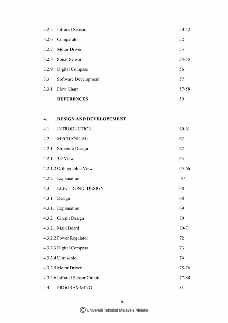
3.2.5 Infrared Sensors 50-52
3.2.6 Comparator 52
3.2.7 Motor Driver 53
3.2.8 Sonar Sensor 54-55
3.2.9 Digital Compass 56
3.3 Software Development 57
3.3.1 Flow Chart 57-58
REFERE�CES 59
4. DESIG� A�D DEVELOPEME�T
4.1 INTRODUCTION 60-61
4.2 MECHANICAL 62
4.2.1 Structure Design 62
4.2.1.1 3D View 63
4.2.1.2 Orthographic View 65-66
4.2.2 Explanation 67
4.3 ELECTRONIC DESIGN 68
4.3.1 Design 68
4.3.1.1 Explanation 69
4.3.2 Circuit Design 70
4.3.2.1 Main Board 70-71
4.3.2.2 Power Regulator 72
4.3.2.3 Digital Compass 73
4.3.2.4 Ultrasonic 74
4.3.2.5 Motor Driver 75-76
4.3.2.6 Infrared Sensor Circuit 77-80
4.4 PROGRAMMING 81
x
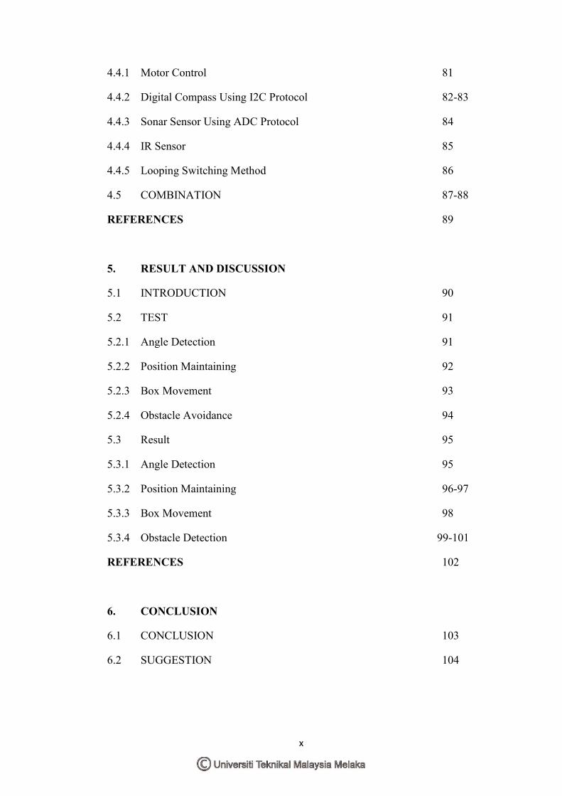
4.4.1 Motor Control 81
4.4.2 Digital Compass Using I2C Protocol 82-83
4.4.3 Sonar Sensor Using ADC Protocol 84
4.4.4 IR Sensor 85
4.4.5 Looping Switching Method 86
4.5 COMBINATION 87-88
REFERE�CES 89
5. RESULT A�D DISCUSSIO�
5.1 INTRODUCTION 90
5.2 TEST 91
5.2.1 Angle Detection 91
5.2.2 Position Maintaining 92
5.2.3 Box Movement 93
5.2.4 Obstacle Avoidance 94
5.3 Result 95
5.3.1 Angle Detection 95
5.3.2 Position Maintaining 96-97
5.3.3 Box Movement 98
5.3.4 Obstacle Detection 99-101
REFERE�CES 102
6. CO�CLUSIO�
6.1 CONCLUSION 103
6.2 SUGGESTION 104
xi
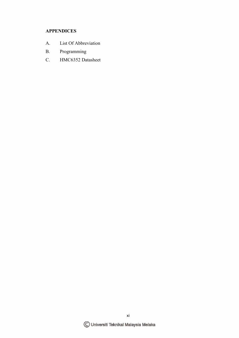
APPE�DICES
A. List Of Abbreviation
B. Programming
C. HMC6352 Datasheet
xii
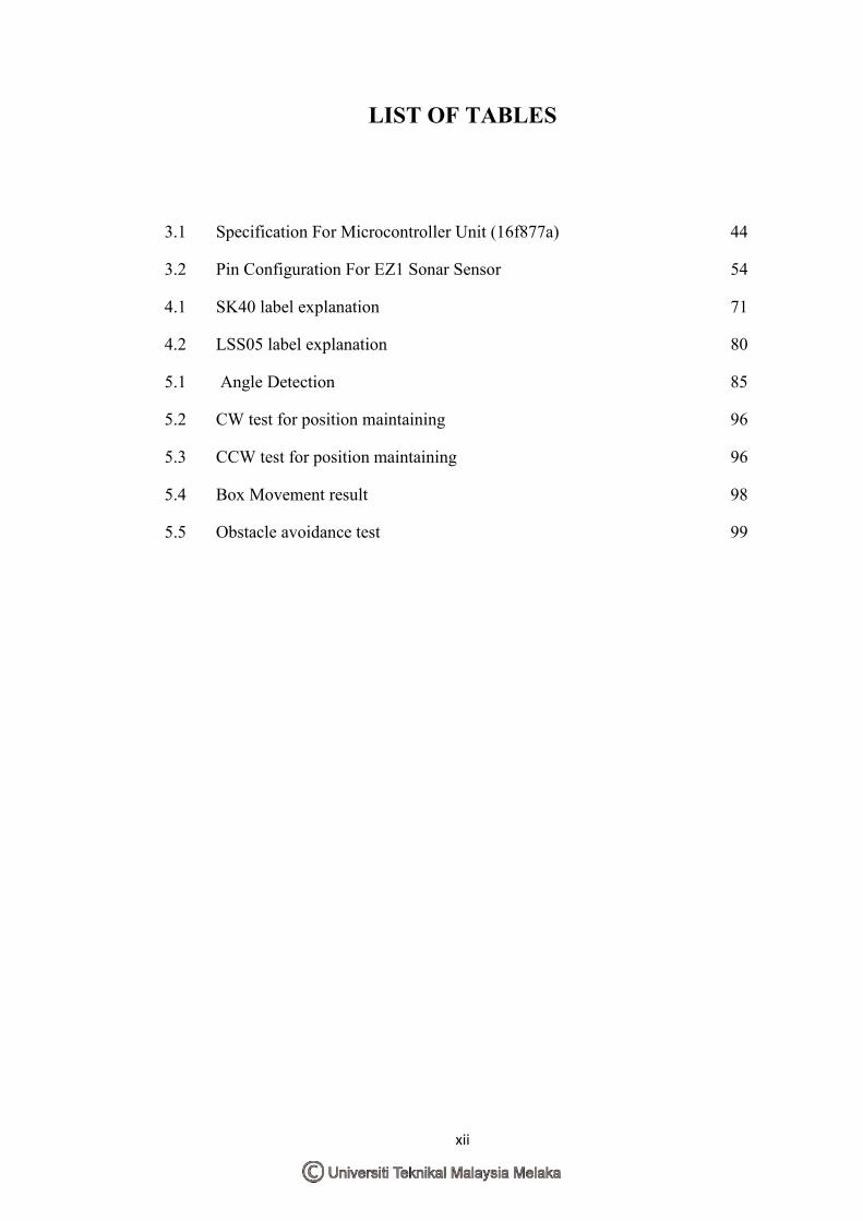
LIST OF TABLES
3.1 Specification For Microcontroller Unit (16f877a) 44
3.2 Pin Configuration For EZ1 Sonar Sensor 54
4.1 SK40 label explanation 71
4.2 LSS05 label explanation 80
5.1 Angle Detection 85
5.2 CW test for position maintaining 96
5.3 CCW test for position maintaining 96
5.4 Box Movement result 98
5.5 Obstacle avoidance test 99
xiii
LIST OF FIGURES
1.0 One Type of Certasian Robot 1
1.1 Sojourner 2
1.2 Pioneer 3
1.3 Dante II 3
1.4 VC-RP30W 4
2.0 Telemetry Interface created using Visual Basic 8 10
2.1 Overall Electrical architecture of the robot 11
2.2 Data Acquisition and Process from Ultrasonic Sensor 13
2.3 Localization under Kidnapping Situation 14
2.4 Path without obstacle 16
2.5 Path with obstacle 16
2.6 Robot sketch 16
2.7 Robot Rotation Sketch 17
2.8 Obstacle Longer Than 1m 18
2.9 Honeywell Digital Compass HMC6352 19
2.10 High Performance Sonar Range Finder 21
2.11 LM324N Pin function 21
2.12 L293D 25
2.13 PIC16F877A 26
2.14 LM7805 27
2.15 LM7805 pin function 27
3.1 Environment Example 41
xiv
3.2 Obstacle Avoiding 42
3.5 16F877A 43
3.6 16F877A Pin Function 44
3.7 NiCad Battery 45
3.8 9V Battery 46
3.9 DC motor cut through 47
3.9.1 LM7805 48
3.9.2 LM7805 Pin function 48
3.9.3 IR Sensor arrangement 49
3.9.4 The Line deactivating Signal 50
3.9.5 The Line activating Signal 50
3.9.6 Comparator LM324N 51
3.9.7 L293D 52
3.9.8 L293D pin list 52
3.9.9 Sonar Sensor LV-MaxSonar-EZ1 53
3.9.10 EZ1 pin list 53
3.9.11 HMC 6352 55
3.9.12 MikroC 57
3.9.13 PicKit 2 57
3.9.14 Cytron USB ICSP Pic Programmer 57
4.1 Isometric view 63
4.2 Isometric X-Ray View 63
4.3 3D view for all components 64
4.4 Top View 65
4.5 Front View 65
4.6 Back View and Side View 66
xv
4.7 Bottom View 66
4.8 Compartment 67
4.9 Placeholder for 3 sensors (a)Compass (b) ultrasonic (c)infrared 68
4.91 Compass Placement 69
4.9.2 Sonar Sensor placement 69
4.93 Infrared Sensor Placement 69
4.94 Main Board 70
4.95 Top View SK40 71
4.96 Power Regulator Circuit 72
4.97 PCB for power regulator 72
4.98 Power Regulator Actual View 72
4.99 Digital Compass connection 73
4.9.1 PCB compass 73
4.9.2 Actual PCB circuit for Digital compass 73
4.9.3 Ultrasonic Circuit 74
4.9.4 Ultrasonic PCB Circuit 74
4.9.5 Actual PCB circuit for Ultrasonic 74
4.9.6 Motor Driver Circuit 75
4.9.7 Motor Driver PCB Circuit 76
4.9.8 Actual PCB circuit for Motor Driver 76
4.9.9 IR sensor circuit 77
4.9.10 IR sensor circuit PCB 77
4.9.11 Actual Circuit 77
4.9.12 Comparator circuit 78
4.9.13 Comparator PCB Circuit 79
4.9.14 Actual PCB Comparator Circuit 79
4.9.15 LSS05 80
xvi
4.9.16 Whole Component combines 87
4.9.17 Whole Component combines 2 88
5.1 Test setup (green – 0 to 5o) and (blue - <90
o) 91
5.2 Test setup for maintaining angle. 92
5.3 Test setup for box movement. 93
5.4 Test setup for obstacle avoidance 94
5.5 Special If loop for IR 100
5.6 Compass tilt angle 101
xvii
LIST OF FLOWCHARTS
3.1.1 FULL OPERATION PROCESS 30
3.1.2 FLOW CHART: MCU START 32
3.1.3 FLOW CHART: ACTUATOR MOVEMENT 34
3.1.4 FLOW CHART: IR SENSOR 36
3.1.5 FLOW CHART: SONAR SENSOR 38
3.1.6 FLOW CHART: DIGITAL COMPASS 40
3.3.1 Flow Chart 57
1
CHAPTER 1
I�TRODUCTIO�
1.0 Introduction
This chapter will mainly discuss about the introduction of the robots navigation
methods trough unknown terrain and also types of robots that has the intelligence to
move and navigate on its own.
1.1 Background Study
Robot can be defined as:
a. A mechanical device that sometimes resembles a human being and is capable
of performing a variety of often complex human tasks on command or by being
programmed in advance. [1]
b. A machine or device that operates automatically or by remote control.
According to Isaac Asimov's, robots must follow 3 laws of robotics. The laws are:
a. A robot may not injure a human being, or, through inaction, allow a human
being to come to harm.
b. A robot must obey the orders given it by human beings except where such
orders would conflict with the First Law.
c. A robot must protect its own existence as long as such protection does not
conflict with the First or Second Law.
2
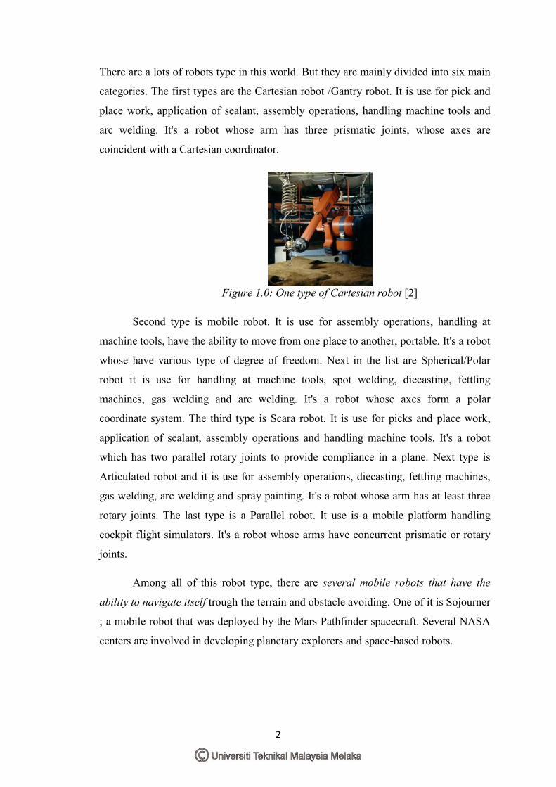
There are a lots of robots type in this world. But they are mainly divided into six main
categories. The first types are the Cartesian robot /Gantry robot. It is use for pick and
place work, application of sealant, assembly operations, handling machine tools and
arc welding. It's a robot whose arm has three prismatic joints, whose axes are
coincident with a Cartesian coordinator.
Figure 1.0: One type of Cartesian robot [2]
Second type is mobile robot. It is use for assembly operations, handling at
machine tools, have the ability to move from one place to another, portable. It's a robot
whose have various type of degree of freedom. Next in the list are Spherical/Polar
robot it is use for handling at machine tools, spot welding, diecasting, fettling
machines, gas welding and arc welding. It's a robot whose axes form a polar
coordinate system. The third type is Scara robot. It is use for picks and place work,
application of sealant, assembly operations and handling machine tools. It's a robot
which has two parallel rotary joints to provide compliance in a plane. Next type is
Articulated robot and it is use for assembly operations, diecasting, fettling machines,
gas welding, arc welding and spray painting. It's a robot whose arm has at least three
rotary joints. The last type is a Parallel robot. It use is a mobile platform handling
cockpit flight simulators. It's a robot whose arms have concurrent prismatic or rotary
joints.
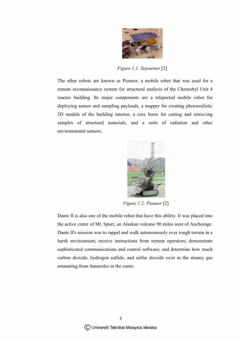
Among all of this robot type, there are several mobile robots that have the
ability to navigate itself trough the terrain and obstacle avoiding. One of it is Sojourner
; a mobile robot that was deployed by the Mars Pathfinder spacecraft. Several NASA
centers are involved in developing planetary explorers and space-based robots.
3
Figure 1.1: Sojourner [2]
The other robots are known as Pioneer; a mobile robot that was used for a
remote reconnaissance system for structural analysis of the Chernobyl Unit 4
reactor building. Its major components are a teleported mobile robot for
deploying sensor and sampling payloads, a mapper for creating photorealistic
3D models of the building interior, a core borer for cutting and retrieving
samples of structural materials, and a suite of radiation and other
environmental sensors.
Figure 1.2: Pioneer [2]
Dante II is also one of the mobile robot that have this ability. It was placed into
the active crater of Mt. Spurr, an Alaskan volcano 90 miles west of Anchorage.
Dante II's mission was to rappel and walk autonomously over rough terrain in a
harsh environment; receive instructions from remote operators; demonstrate
sophisticated communications and control software; and determine how much
carbon dioxide, hydrogen sulfide, and sulfur dioxide exist in the steamy gas
emanating from fumaroles in the crater.
4
Figure 1.3: Dante II [2]
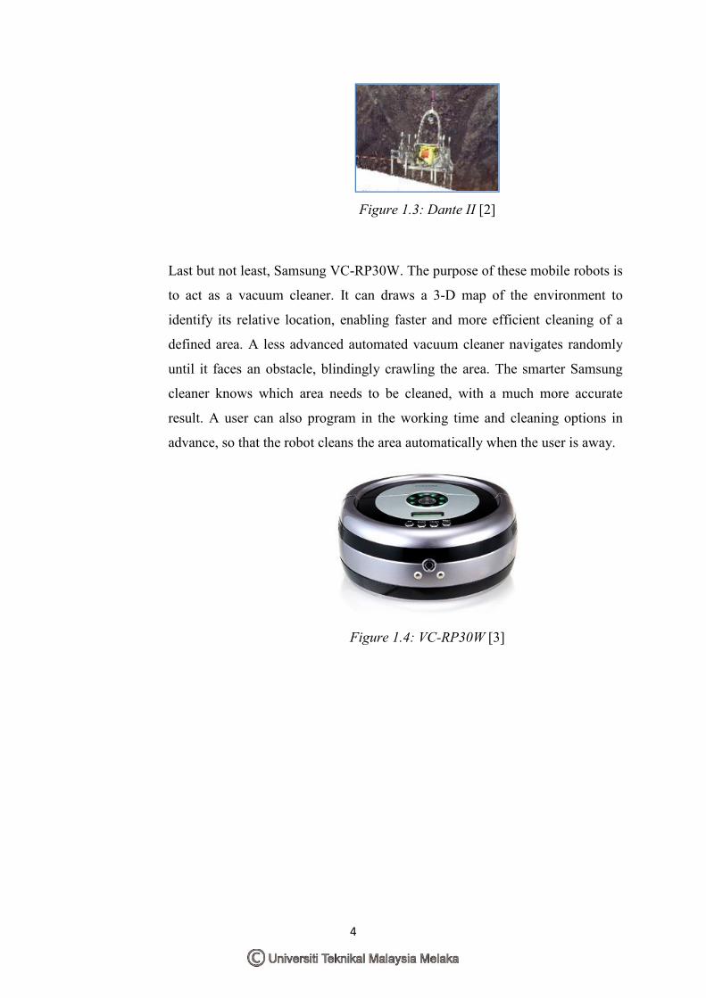
Last but not least, Samsung VC-RP30W. The purpose of these mobile robots is
to act as a vacuum cleaner. It can draws a 3-D map of the environment to
identify its relative location, enabling faster and more efficient cleaning of a
defined area. A less advanced automated vacuum cleaner navigates randomly
until it faces an obstacle, blindingly crawling the area. The smarter Samsung
cleaner knows which area needs to be cleaned, with a much more accurate
result. A user can also program in the working time and cleaning options in
advance, so that the robot cleans the area automatically when the user is away.
Figure 1.4: VC-RP30W [3]