Embed Size (px)
Citation preview
Development of MitsubishiContinuous Process for
Copper ExtractionMoto Goto
President DirectorPT. Smelting
History of Copper
• Copper is one of the oldest metal• 6,000-8,000 years ago in the East
Europe and the Middle East• 4,000 years ago in China• 2,000 years ago in Japan
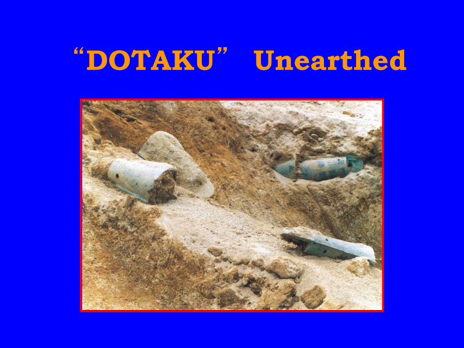
“DOTAKU” Unearthed
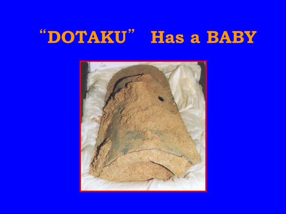
“DOTAKU” Has a BABY
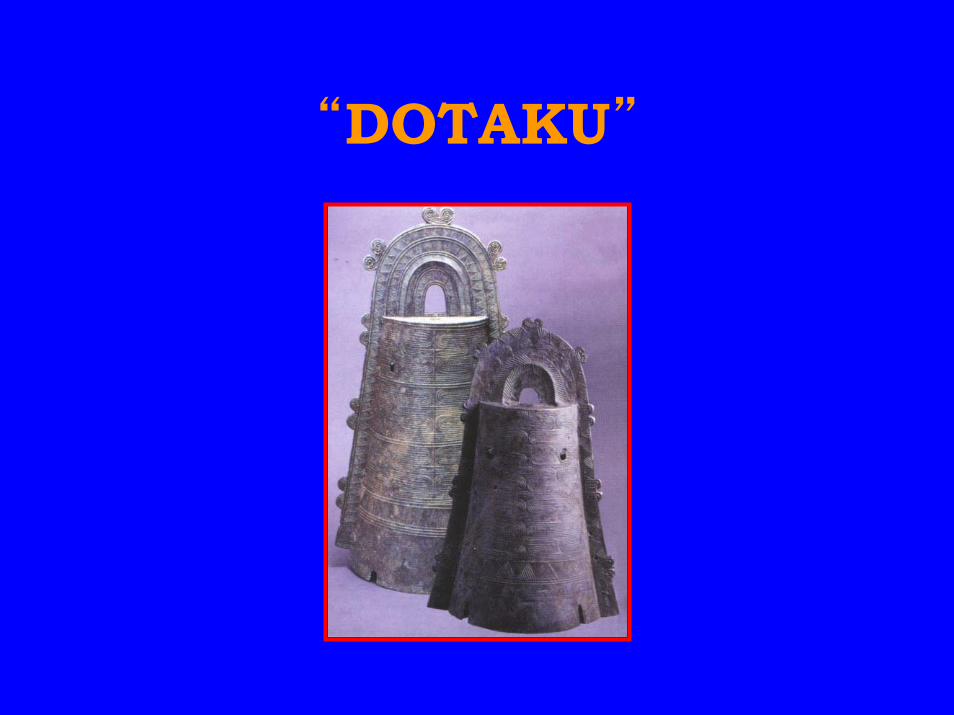
“DOTAKU”
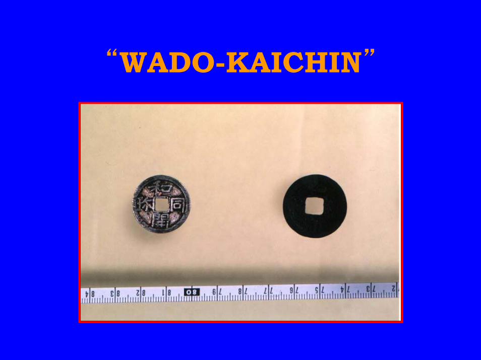
“WADO-KAICHIN”

Buddha in NARA
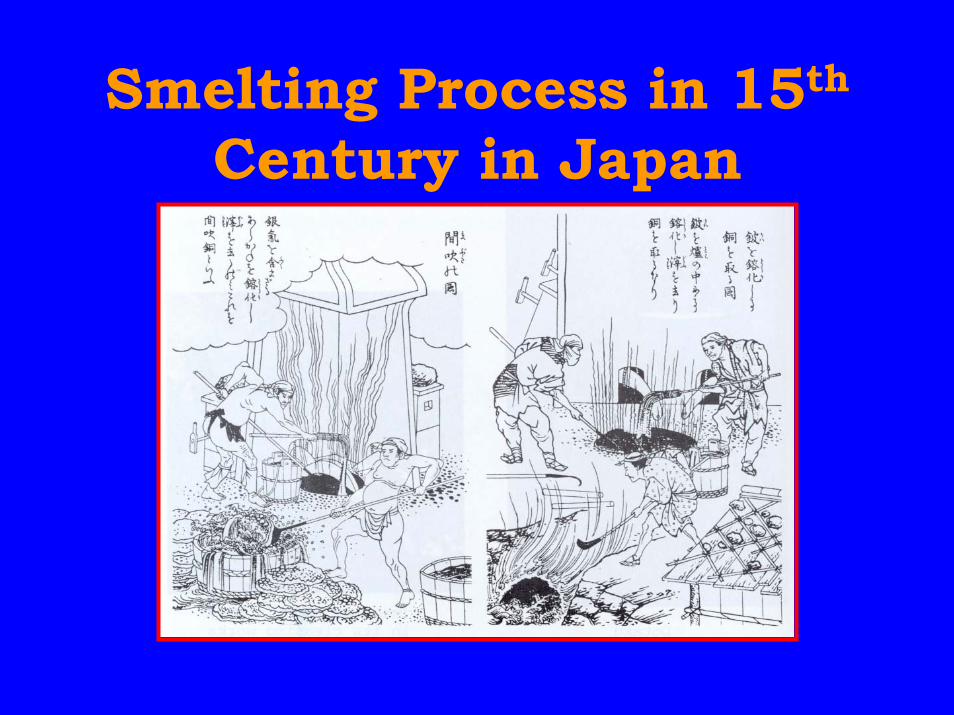
Smelting Process in 15th
Century in Japan
Copper Historyin 16th Century
• Mining and smelting wasimproved in Germany and Japan– High grade copper ore– Good quality of wood as fuel– Good quality clay for hearth making– Blasting technology like hand
bellows and piping
Copper Historyin 17th-19th Century
• Leading countries of copperproduction are Germany, UnitedKingdom, Russia and Japan
• A few thousand tons of copperwas produced in Japan at the endof 17th century
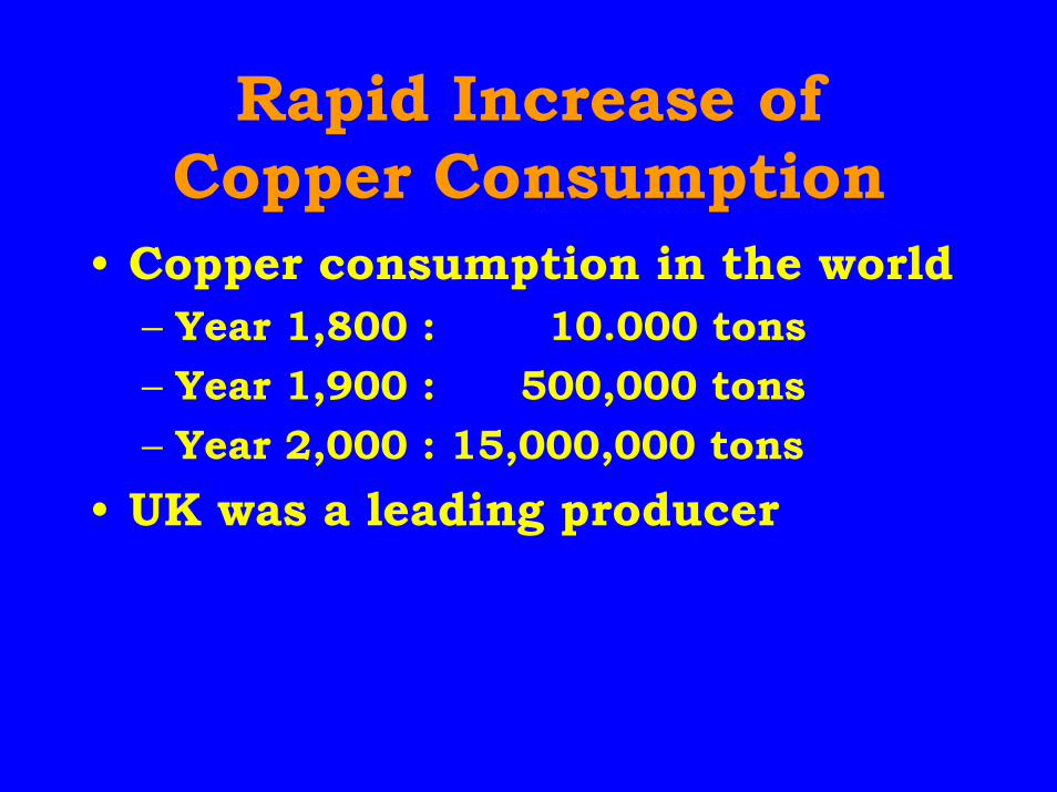
Rapid Increase ofCopper Consumption
• Copper consumption in the world– Year 1,800 : 10.000 tons– Year 1,900 : 500,000 tons– Year 2,000 : 15,000,000 tons
• UK was a leading producer
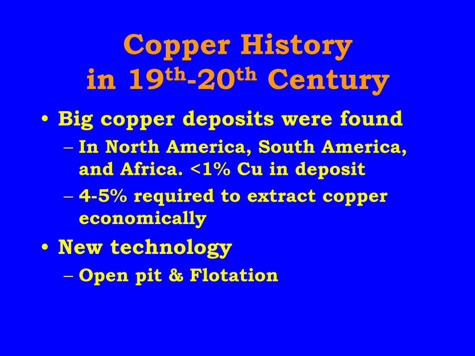
Copper Historyin 19th-20th Century
• Big copper deposits were found– In North America, South America,
and Africa. <1% Cu in deposit– 4-5% required to extract copper
economically• New technology
– Open pit & Flotation
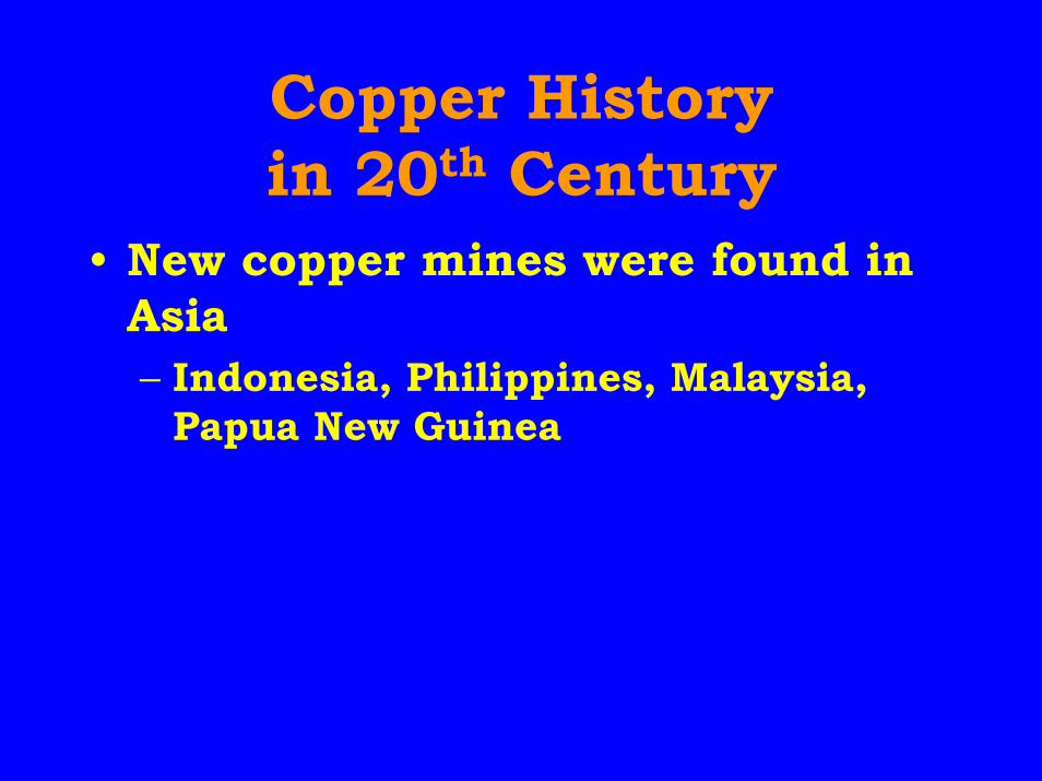
Copper Historyin 20th Century
• New copper mines were found inAsia– Indonesia, Philippines, Malaysia,
Papua New Guinea
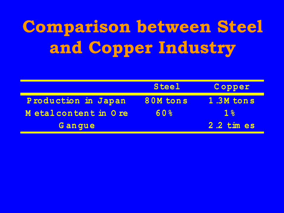
Comparison between Steeland Copper Industry
Steel C opper
Production in Japan 80M tons 1.3M tonsM etal content in O re 60% 1%
G an gue 2.2 tim es
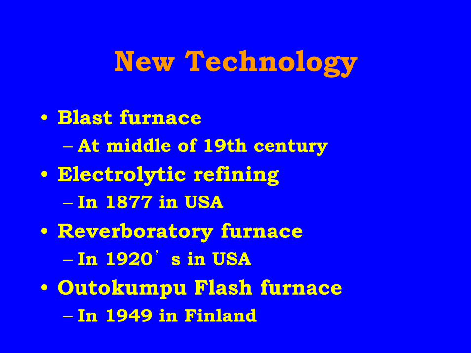
New Technology
• Blast furnace– At middle of 19th century
• Electrolytic refining– In 1877 in USA
• Reverboratory furnace– In 1920’s in USA
• Outokumpu Flash furnace– In 1949 in Finland
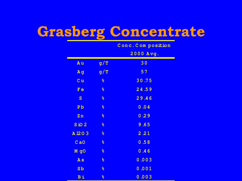
Grasberg ConcentrateC onc. C om position
2000 A vg.
A u g/T 30
A g g/T 57
C u % 30.75
Fe % 24.59
S % 29.46
Pb % 0.04
Zn % 0.29
SiO 2 % 9.65
A l2O 3 % 2.21
C aO % 0.58
M gO % 0.46
A s % 0.003
Sb % 0.001
B i % 0.003
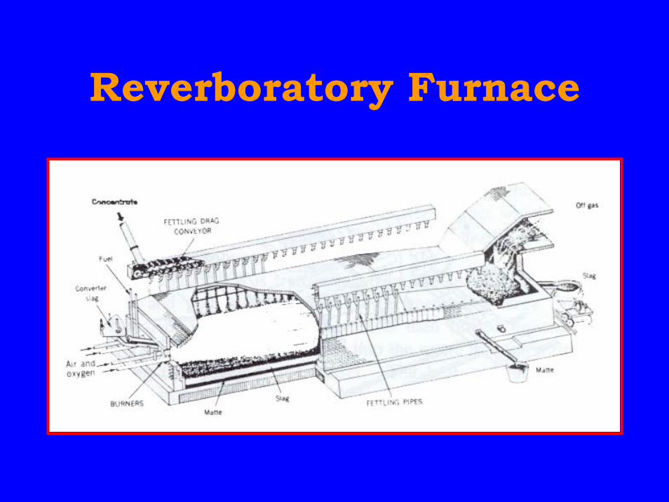
Reverboratory Furnace
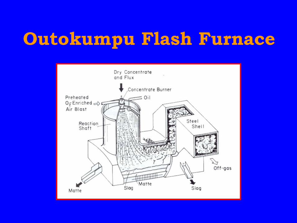
Outokumpu Flash Furnace
Conventional ProcessNow in Use
• Smelting furnace– Electric furnace, Outokumpu flash
furnace, Inco flash furnace, Norandareactor
• with batch-wise converters– Peirce-Smith converter
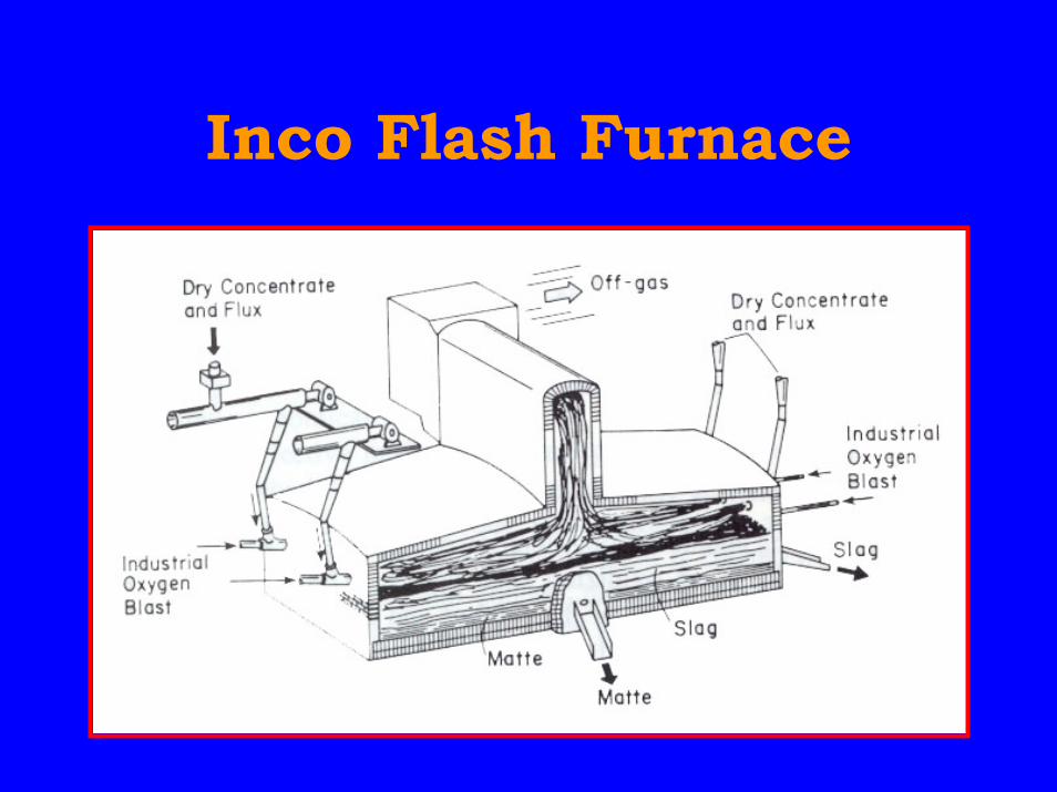
Inco Flash Furnace
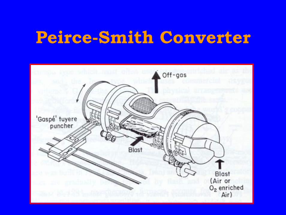
Peirce-Smith Converter
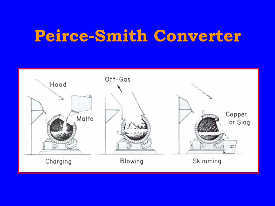
Peirce-Smith Converter

Hood for PS Converter
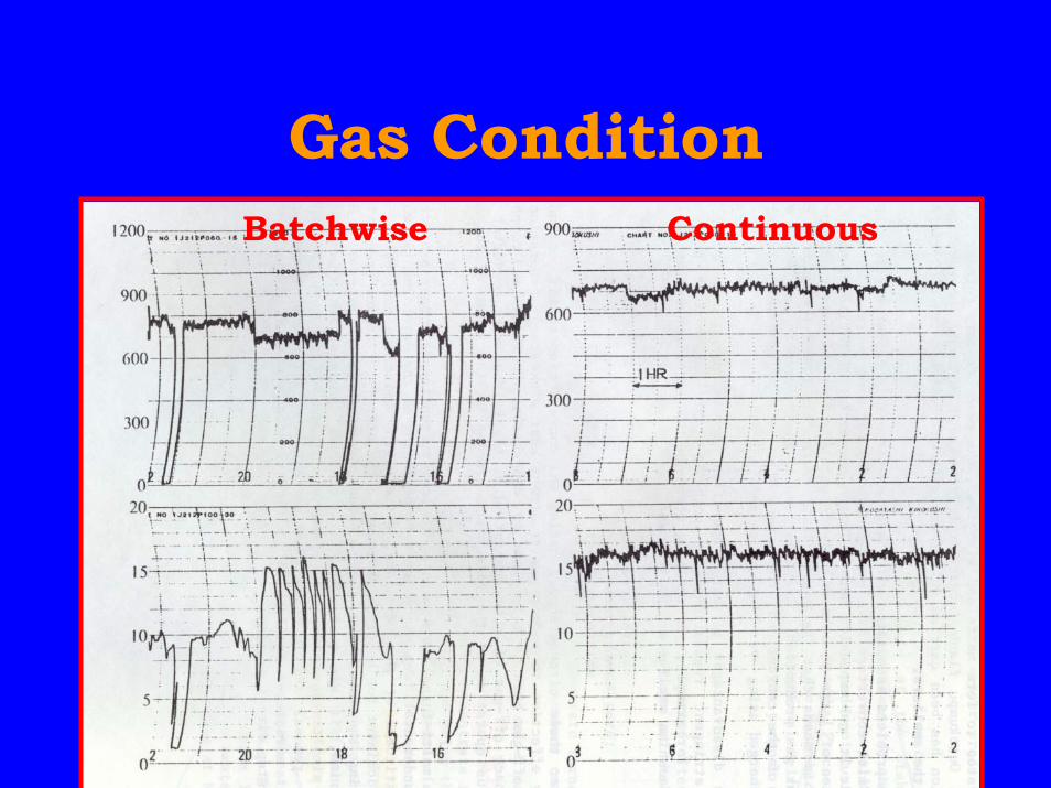
Gas ConditionBatchwise Continuous
Continuous Converting
• In 1959 (Pioneer)– at Balhashi in Kazakhstan then in
Szekoslovakia• In 1960’s
– Worcra process in Australia– Noranda process in Canada– Mitsubishi process in Japan
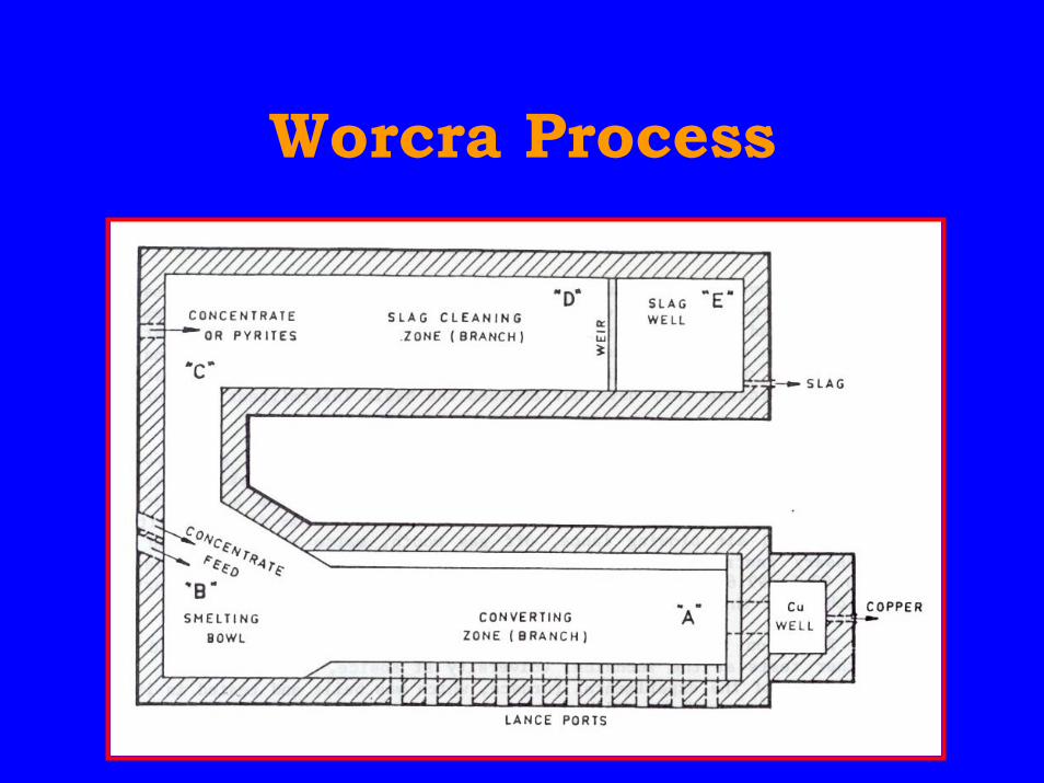
Worcra Process
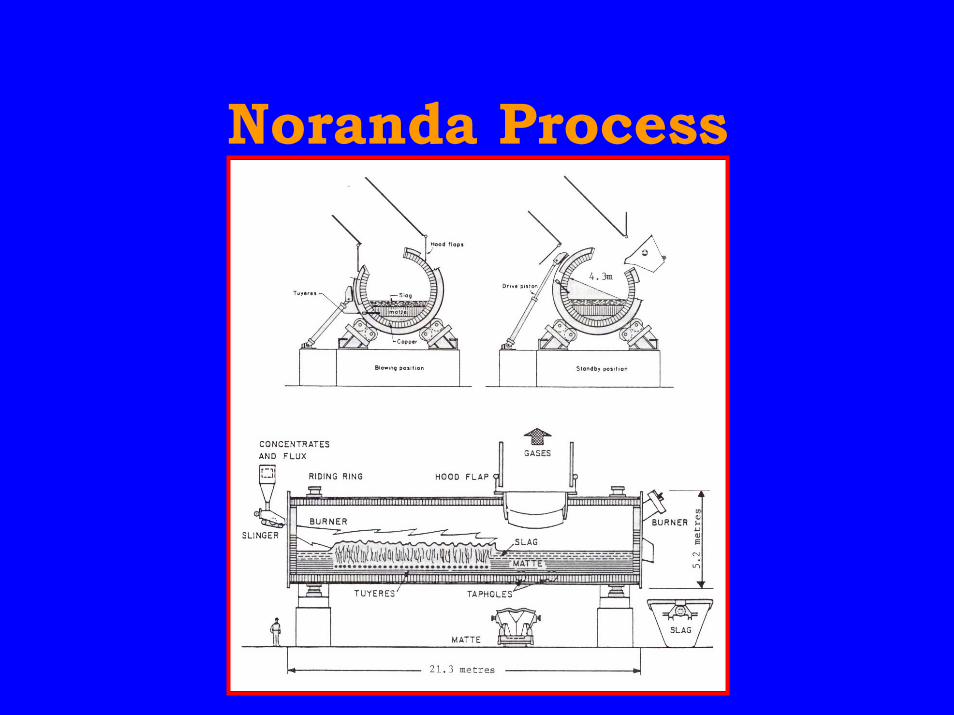
Noranda Process
Mitsubishi Process
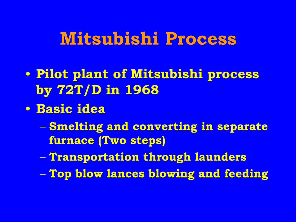
• Pilot plant of Mitsubishi processby 72T/D in 1968
• Basic idea– Smelting and converting in separate
furnace (Two steps)– Transportation through launders– Top blow lances blowing and feeding
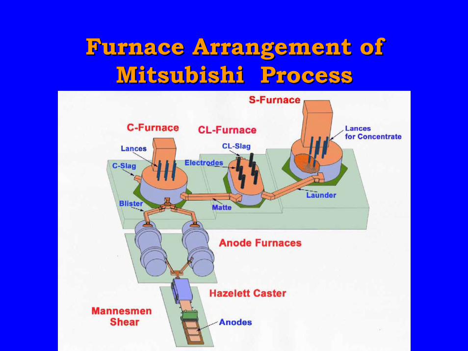
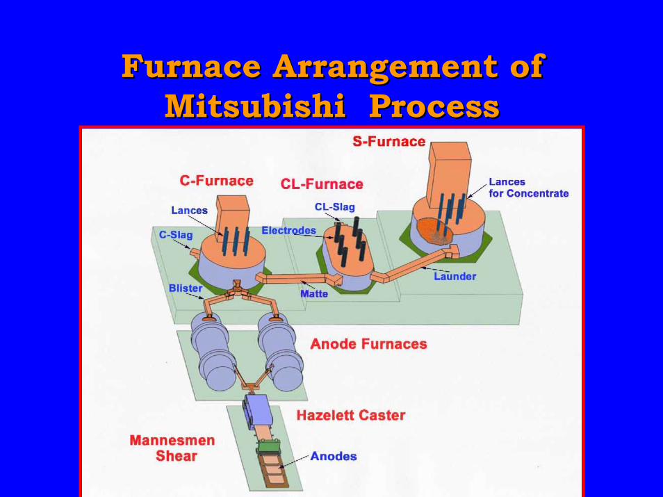
Furnace Arrangement ofFurnace Arrangement ofMitsubishi ProcessMitsubishi Process
C F’ce CL F’ce S F’ce
Anode F’ce
Lances
Lancesforconcentrate
Hazelett Caster
Matte
LaunderBlister
CL-Slag
Electrodes
MannesmanShear
C-Slag
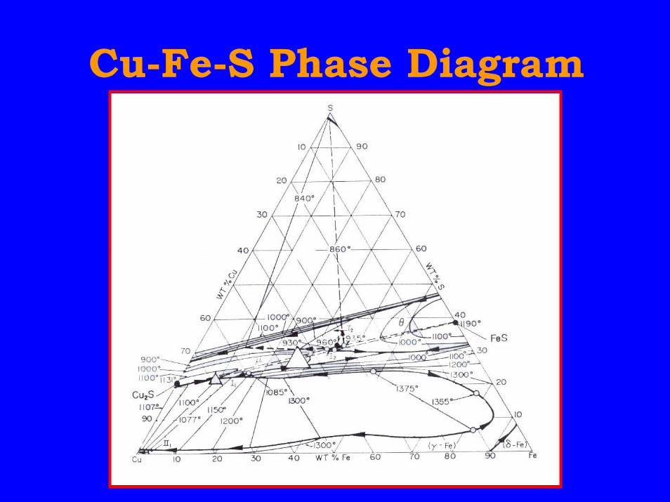
Cu-Fe-S Phase Diagram
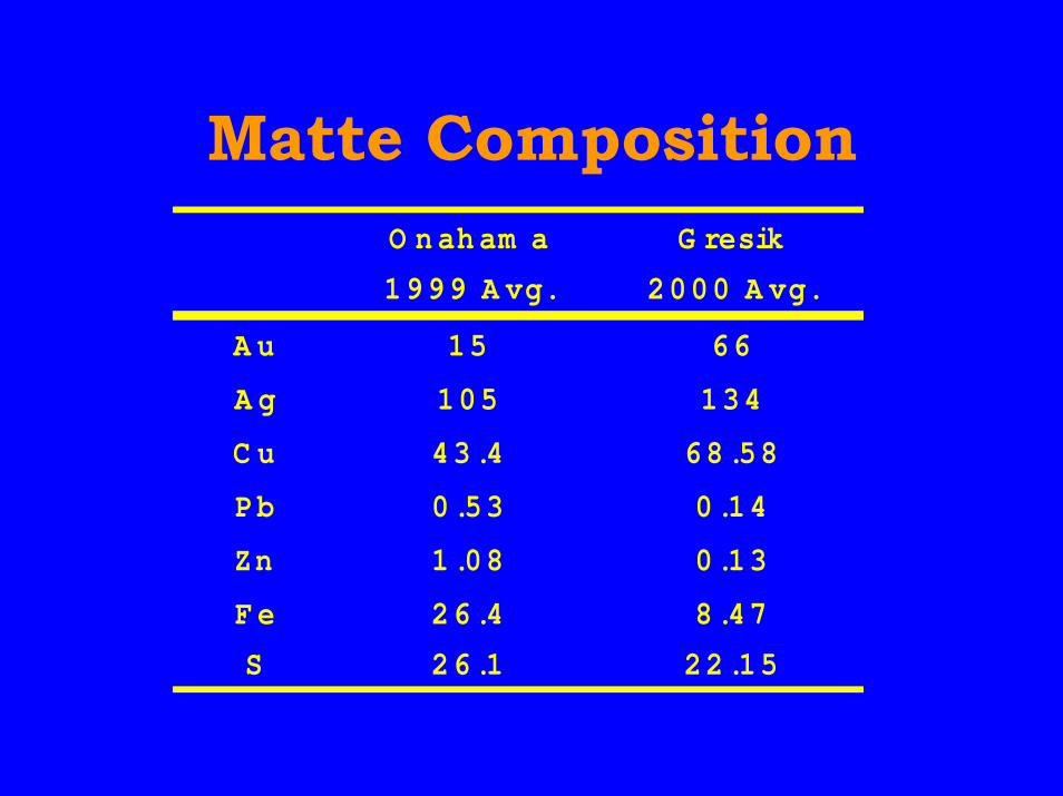
Matte CompositionO naham a G resik
1999 A vg. 2000 A vg.
A u 15 66
A g 105 134
C u 43.4 68.58
Pb 0.53 0.14
Zn 1.08 0.13
Fe 26.4 8.47
S 26.1 22.15
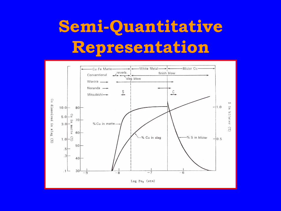
Semi-QuantitativeRepresentation
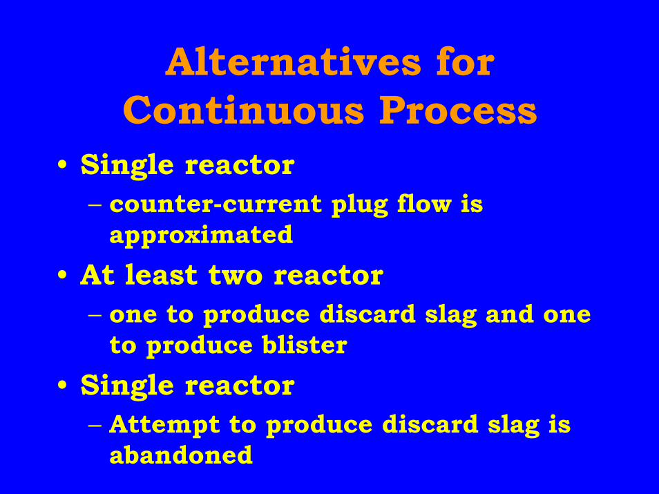
Alternatives forContinuous Process
• Single reactor– counter-current plug flow is
approximated• At least two reactor
– one to produce discard slag and oneto produce blister
• Single reactor– Attempt to produce discard slag is
abandoned
Difficulties ofDirect Extraction
• Insufficient copper recovery fromslag
• Poor minor element elimination
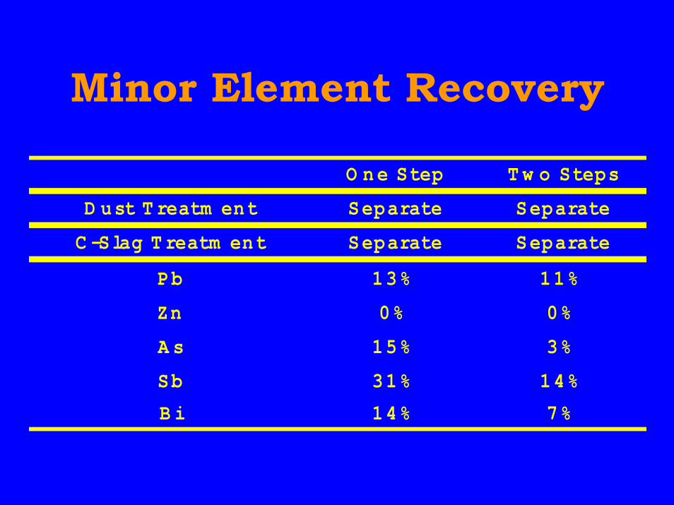
Minor Element Recovery
O ne Step T w o Steps
D ust T reatm ent Separate Separate
C -Slag T reatm ent Separate Separate
Pb 13% 11%
Zn 0% 0%
A s 15% 3%
Sb 31% 14%
B i 14% 7%
Advantage ofInjection Smelting
• Rapid melting and chemicalreaction
• Small mechanical dust generation• Low copper content in slag• High oxygen utilization
Advantage ofTop Blow Lance
• Possible to replace duringoperation
• Reduce damage of refractory• Campaign life of Mitsubishi
Converting furnace is longer thanthat of PS converter
PS Converter Operation
• Two different stage operation– Slag blow stage : oxidation of matte
to produce white metal, iron silicateslag and off gas
– Copper blow stage : oxidation ofwhite metal to produce blistercopper and off gas
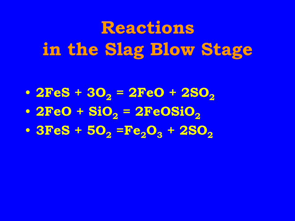
Reactionsin the Slag Blow Stage
• 2FeS + 3O2 = 2FeO + 2SO2
• 2FeO + SiO2 = 2FeOSiO2
• 3FeS + 5O2 =Fe2O3 + 2SO2
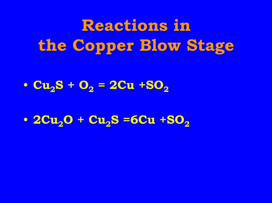
Reactions inthe Copper Blow Stage
• Cu2S + O2 = 2Cu +SO2
• 2Cu2O + Cu2S =6Cu +SO2
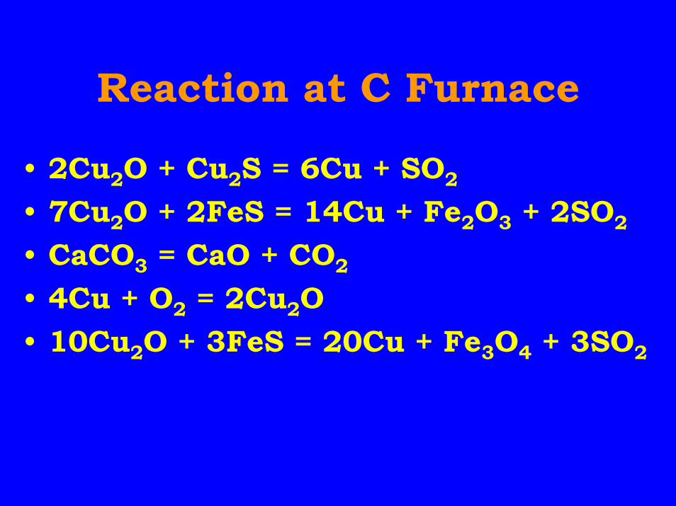
Reaction at C Furnace
• 2Cu2O + Cu2S = 6Cu + SO2
• 7Cu2O + 2FeS = 14Cu + Fe2O3 + 2SO2
• CaCO3 = CaO + CO2
• 4Cu + O2 = 2Cu2O• 10Cu2O + 3FeS = 20Cu + Fe3O4 + 3SO2
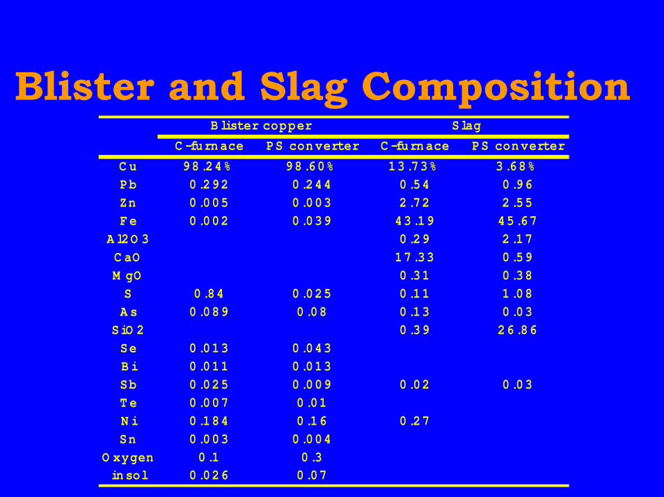
Blister and Slag CompositionB lister copper Slag
C -furnace PS converter C -furnace PS converter
C u 98.24% 98.60% 13.73% 3.68%Pb 0.292 0.244 0.54 0.96Zn 0.005 0.003 2.72 2.55Fe 0.002 0.039 43.19 45.67
A l2O 3 0.29 2.17C aO 17.33 0.59M gO 0.31 0.38S 0.84 0.025 0.11 1.08A s 0.089 0.08 0.13 0.03
SiO 2 0.39 26.86Se 0.013 0.043B i 0.011 0.013Sb 0.025 0.009 0.02 0.03T e 0.007 0.01N i 0.184 0.16 0.27Sn 0.003 0.004
O xygen 0.1 0.3insol 0.026 0.07
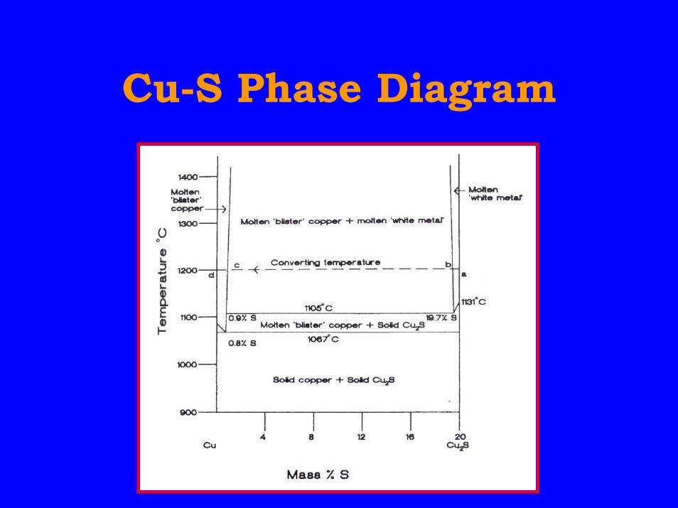
Cu-S Phase Diagram
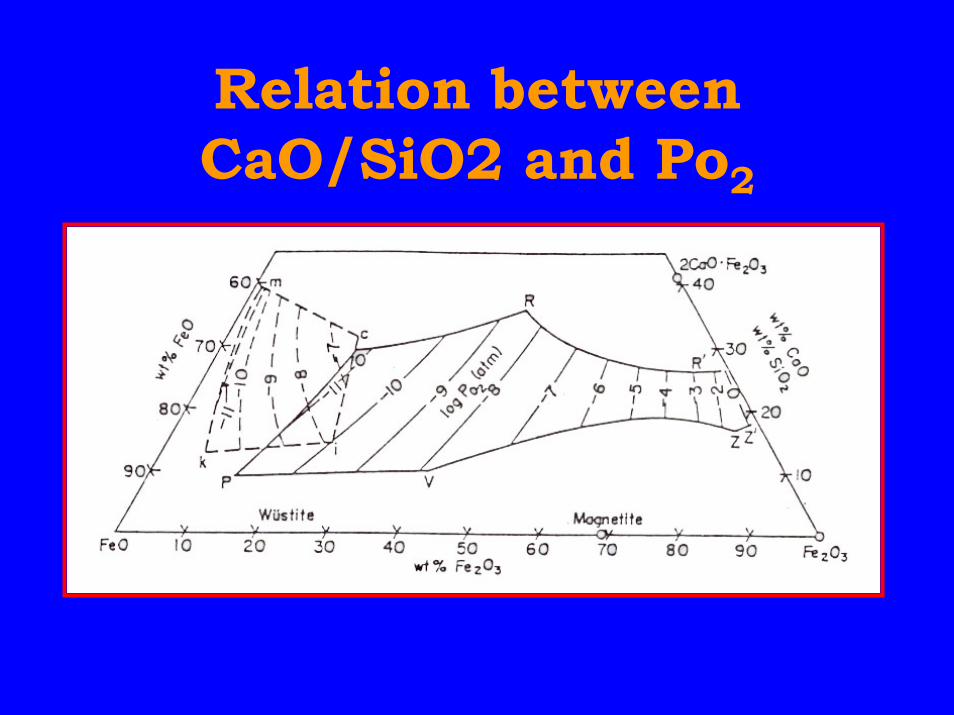
Relation betweenCaO/SiO2 and Po2
Features of theMitsubishi Process
• Continuous operation with multi-furnace constitution
• Injection smelting using top blowlances
• Calcium-ferrite slag forconverting furnace

Furnace Arrangement ofFurnace Arrangement ofMitsubishi ProcessMitsubishi Process
C F’ce CL F’ce S F’ce
Anode F’ce
Lances
Lancesforconcentrate
Hazelett Caster
Matte
LaunderBlister
CL-Slag
Electrodes
MannesmanShear
C-Slag
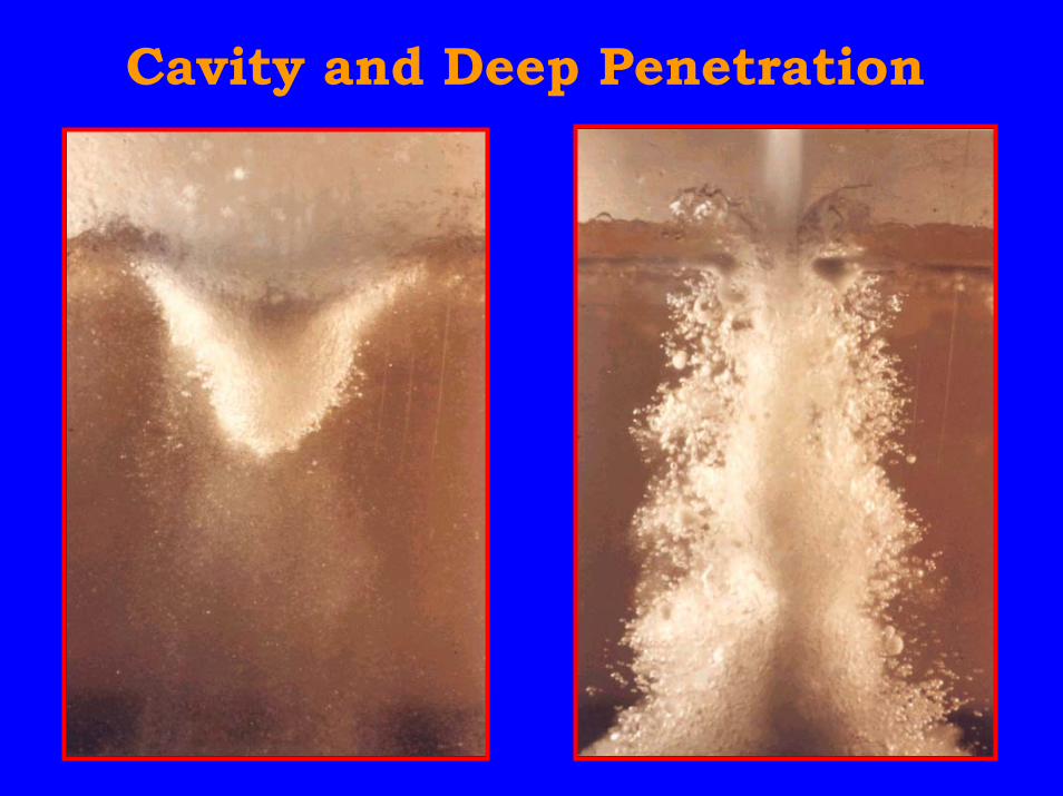
Cavity and Deep Penetration
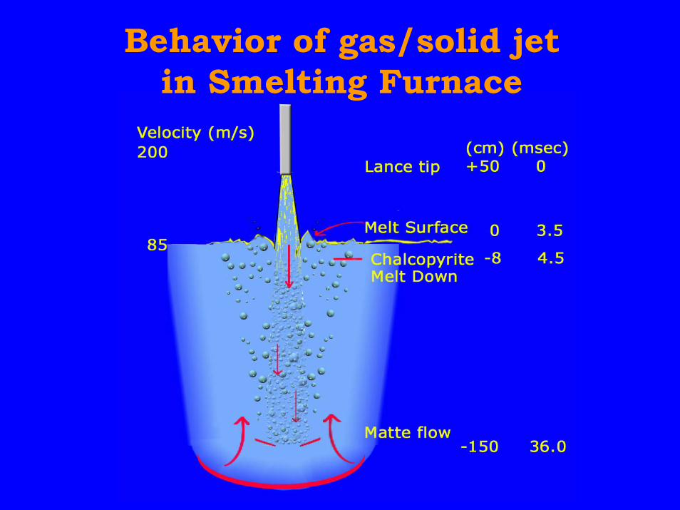
Behavior of gas/solid jetin Smelting Furnace

Furnace Arrangement ofFurnace Arrangement ofMitsubishi ProcessMitsubishi Process
C F’ce CL F’ce S F’ce
Anode F’ce
Lances
Lancesforconcentrate
Hazelett Caster
Matte
LaunderBlister
CL-Slag
Electrodes
MannesmanShear
C-Slag
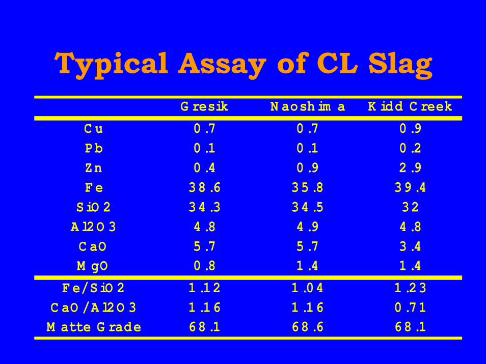
Typical Assay of CL SlagG resik N aosh im a K idd C reek
C u 0.7 0.7 0.9Pb 0.1 0.1 0.2Zn 0.4 0.9 2.9Fe 38.6 35.8 39.4
SiO 2 34.3 34.5 32A l2O 3 4.8 4.9 4.8C aO 5.7 5.7 3.4M gO 0.8 1.4 1.4
Fe/SiO 2 1.12 1.04 1.23C aO /A l2O 3 1.16 1.16 0.71M atte G rade 68.1 68.6 68.1
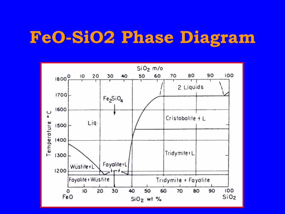
FeO-SiO2 Phase Diagram
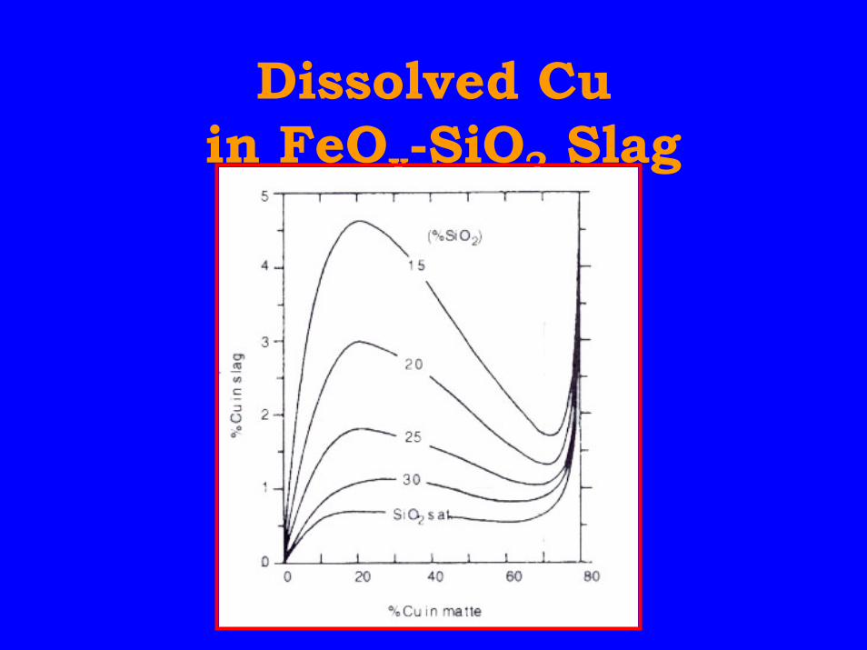
Dissolved Cu in FeOx-SiO2 Slag
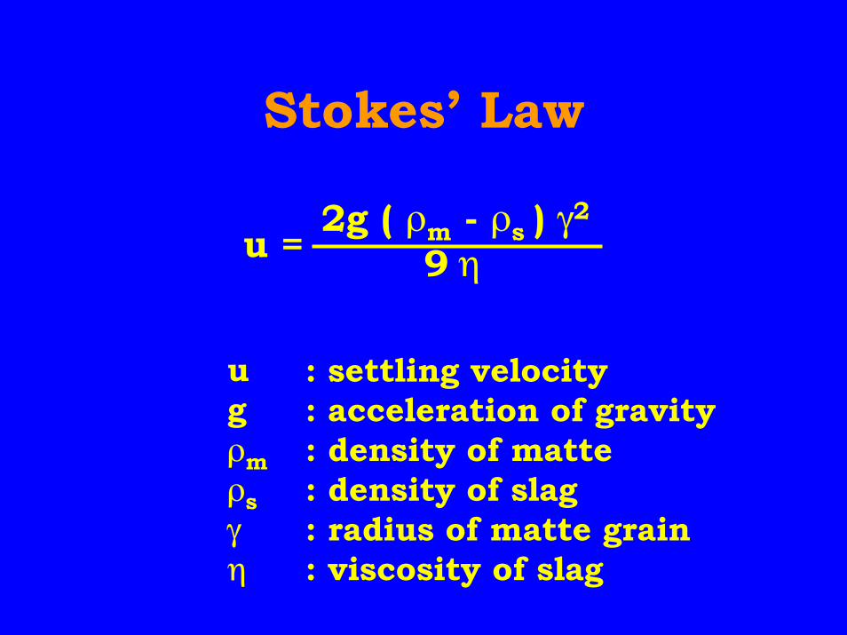
Stokes’ Law
ugρmρsγη
: settling velocity: acceleration of gravity: density of matte: density of slag: radius of matte grain: viscosity of slag
2g ( ρm - ρs ) γ2
9 ηu =
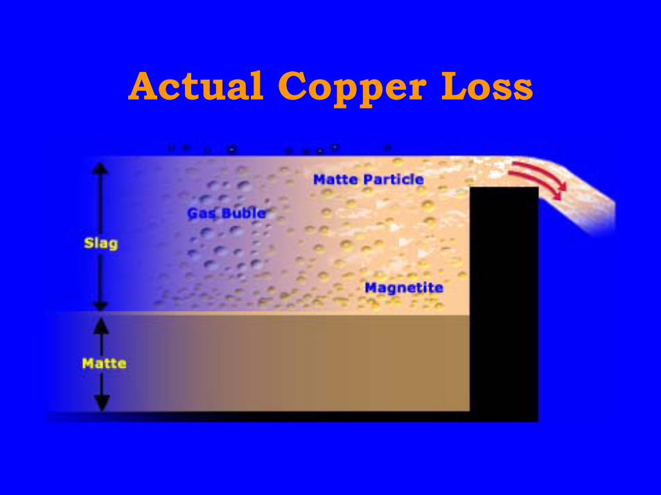
Actual Copper Loss
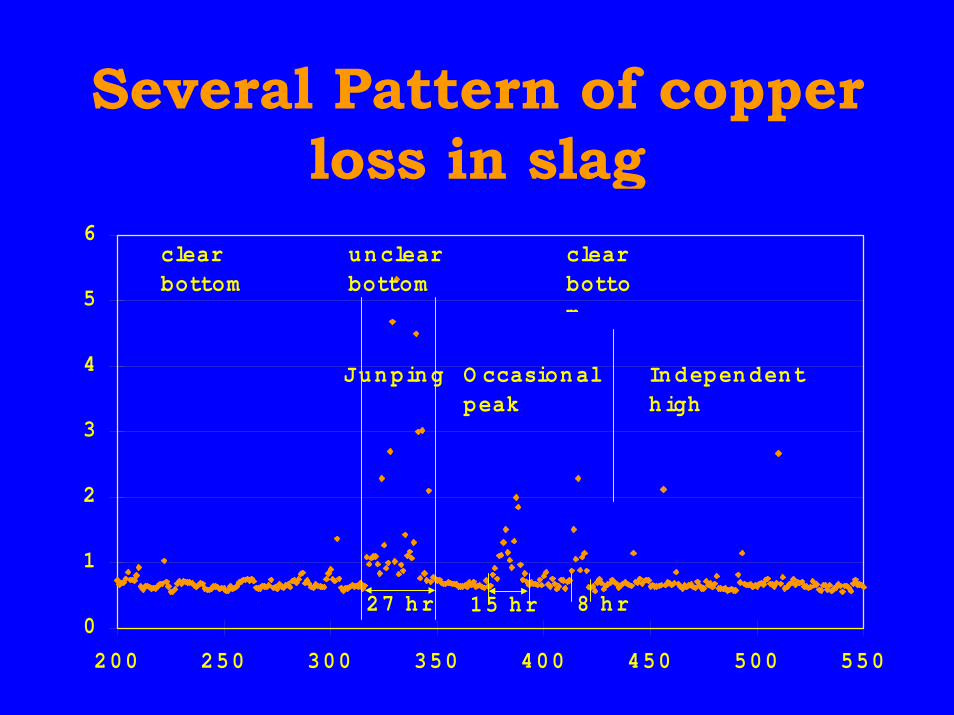
Several Pattern of copperloss in slag
0
1
2
3
4
5
6
200 250 300 350 400 450 500 550
clear bottom
clear bottom
unclear bottom
Junping O ccasional peak
Independenthigh
27 hr 15 hr 8 hr
Furnace Arrangement ofFurnace Arrangement ofMitsubishi ProcessMitsubishi Process
C F’ce CL F’ce S F’ce
Anode F’ce
Lances
Lancesforconcentrate
Hazelett Caster
Matte
LaunderBlister
CL-Slag
Electrodes
MannesmanShear
C-Slag
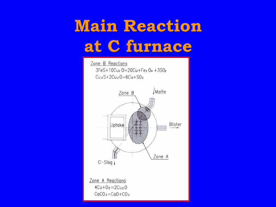
Main Reactionat C furnace
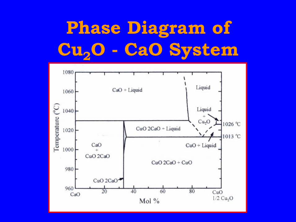
Phase Diagram ofCu2O - CaO System
Kennecott-OutokumpuFlash Converter
• Operation started in 1995 in USA• Matte is granulated by water,
piled, reclaimed, ground, driedand charged to converter
• Independent operation of bothfurnaces
• Additional equipment, additionalenergy and high dust generation
Process Control of Mitsubishi Continuous Process
at Gresik Smelter
M. Goto, R.Kojima, T.Muto and T.Matsutani
Gresik Smelter & Refinery, PT.Smelting
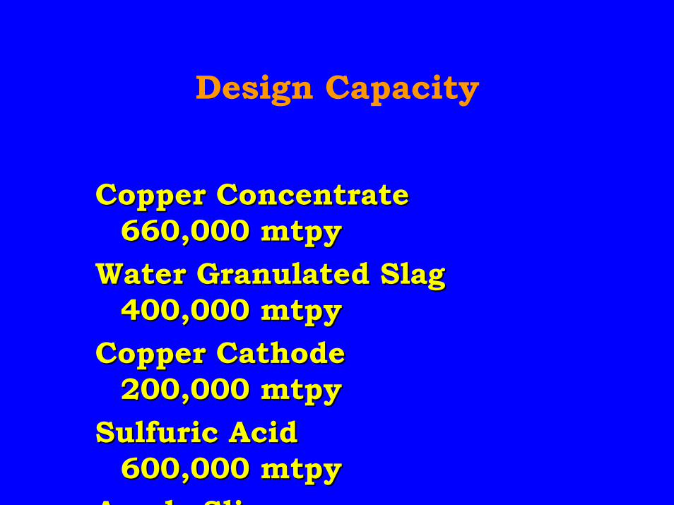
Design Capacity
Copper ConcentrateCopper Concentrate660,000 mtpy660,000 mtpy
Water Granulated SlagWater Granulated Slag400,000 mtpy400,000 mtpy
Copper CathodeCopper Cathode200,000 mtpy200,000 mtpy
Sulfuric AcidSulfuric Acid600,000 mtpy600,000 mtpy
A d SliA d Sli
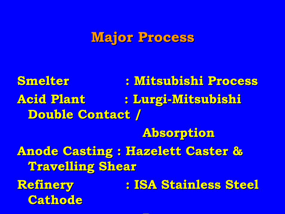
Major ProcessMajor Process
Smelter : Mitsubishi ProcessSmelter : Mitsubishi ProcessAcid Plant : Lurgi-MitsubishiAcid Plant : Lurgi-Mitsubishi
Double Contact /Double Contact / Absorption AbsorptionAnode Casting : Hazelett Caster &Anode Casting : Hazelett Caster &
Travelling ShearTravelling ShearRefinery : ISA Stainless SteelRefinery : ISA Stainless Steel
CathodeCathode P P
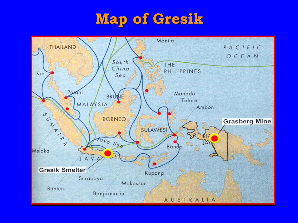
Map of GresikMap of Gresik
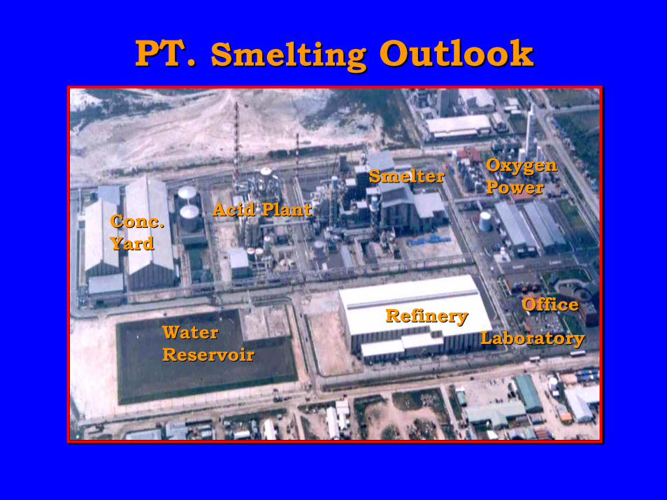
PT. PT. SmeltingSmelting Outlook Outlook
SmelterSmelter
RefineryRefinery
Acid PlantAcid Plant
OfficeOffice
OxygenOxygenPowerPower
WaterWaterReservoirReservoir
LaboratoryLaboratory
Conc.Conc.YardYard
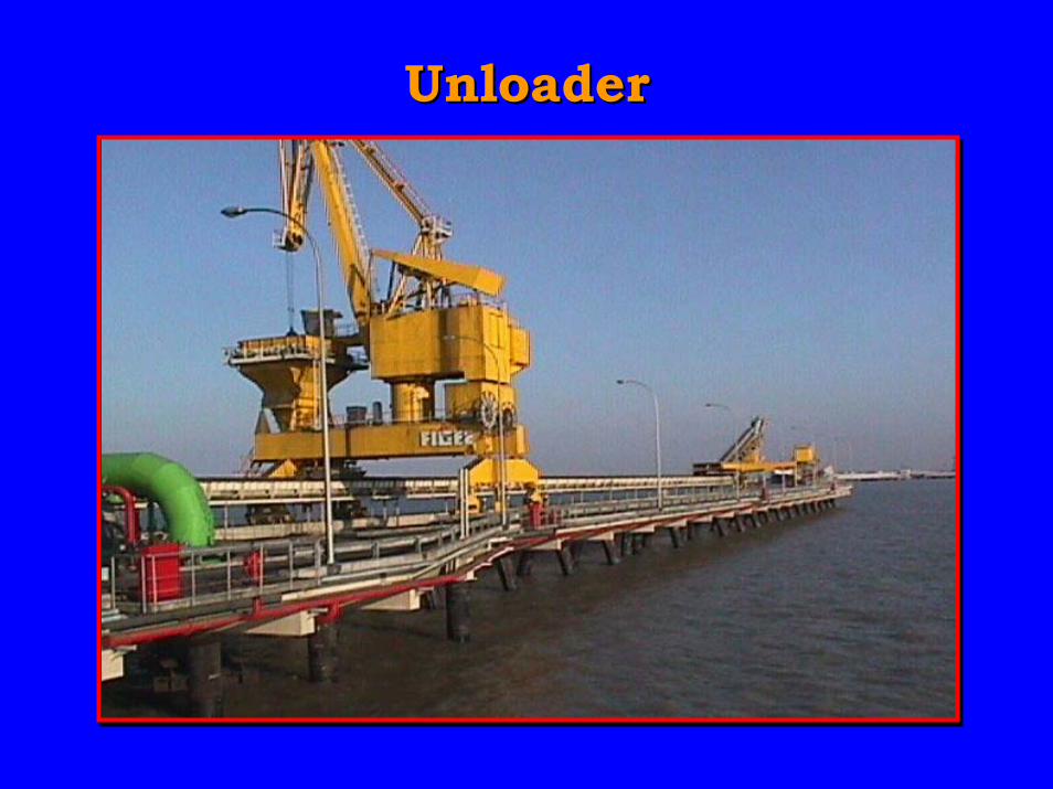
UnloaderUnloader
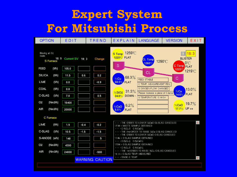
Expert SystemFor Mitsubishi Process
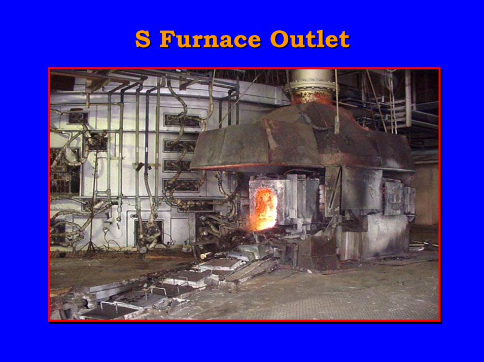
S Furnace OutletS Furnace Outlet
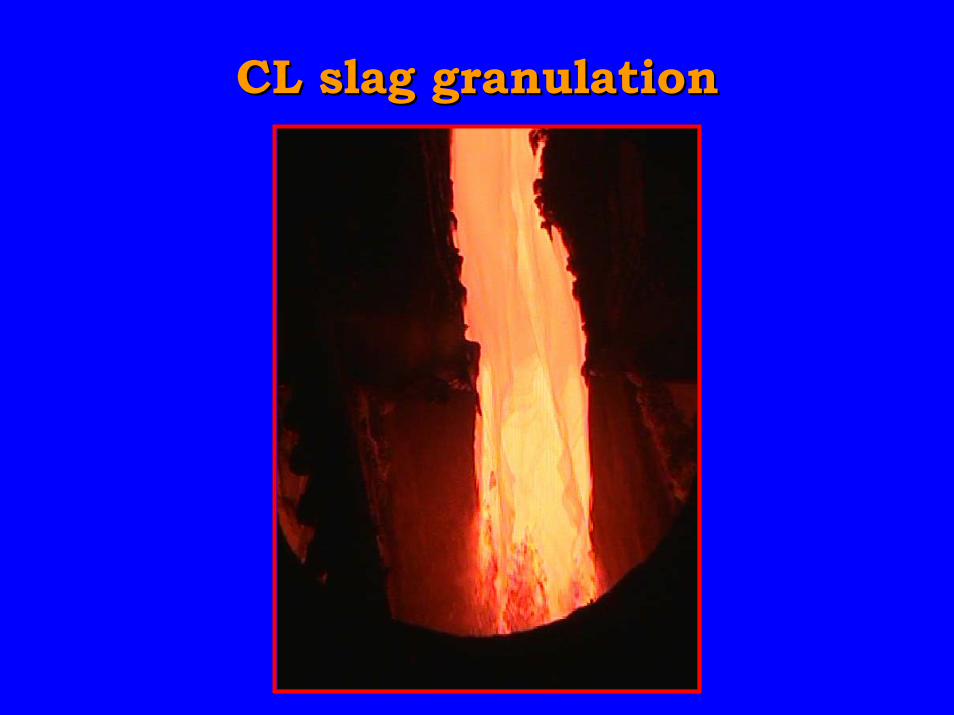
CL slag granulationCL slag granulation
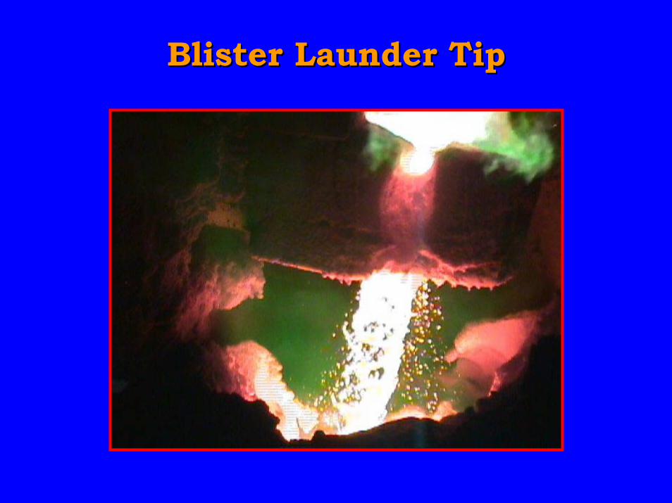
Blister Launder TipBlister Launder Tip
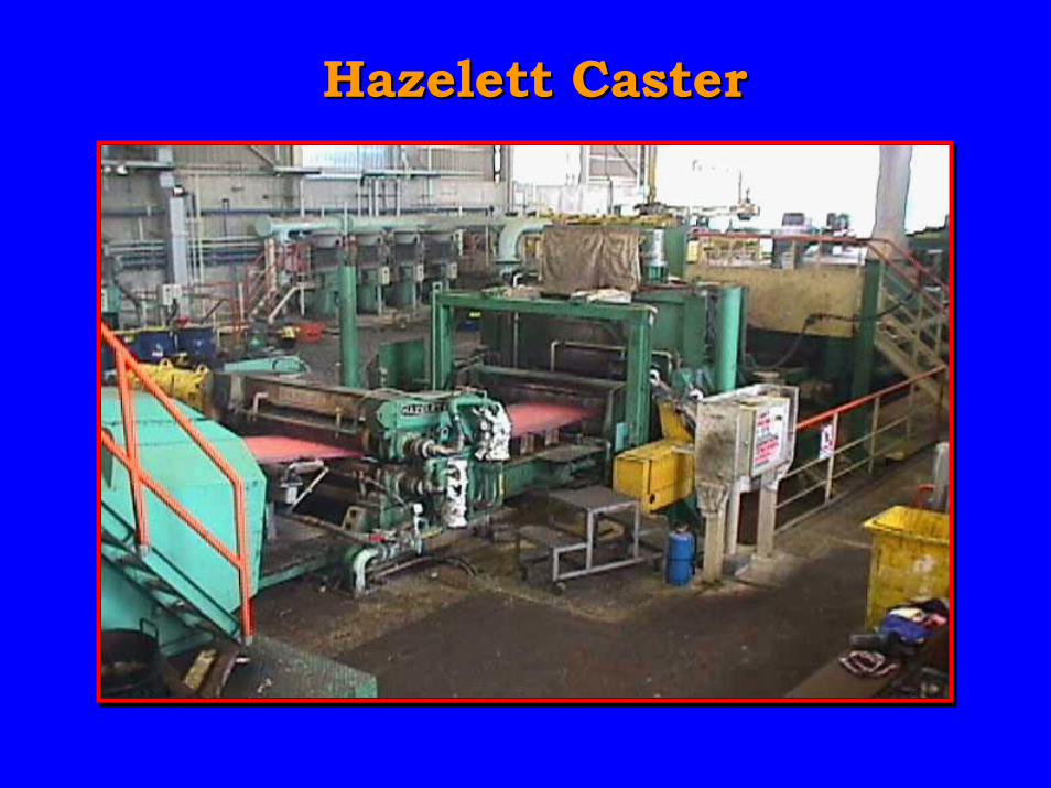
Hazelett CasterHazelett Caster
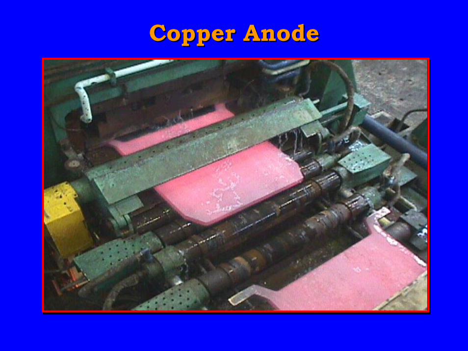
Copper AnodeCopper Anode
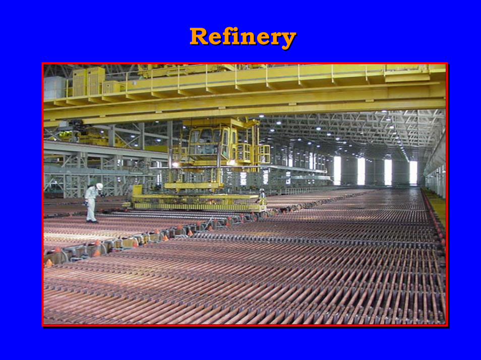
RefineryRefinery
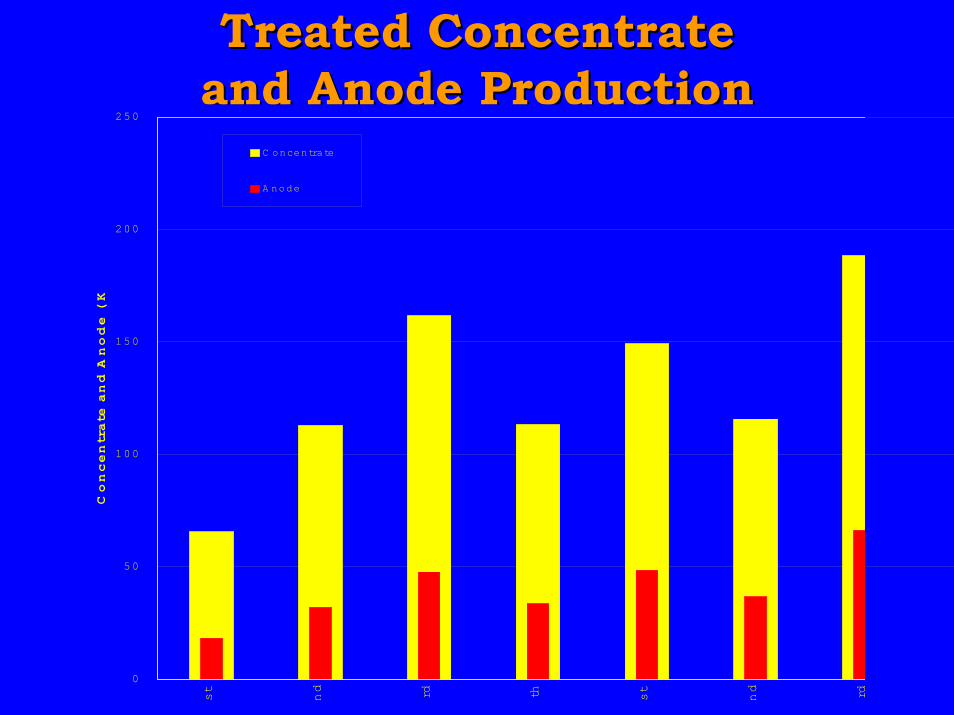
Treated ConcentrateTreated Concentrateand Anode Productionand Anode Production
0
50
100
150
200
250
st
nd rd th st
nd rd
Concentrate and A
node ( K
C oncentrate
A node
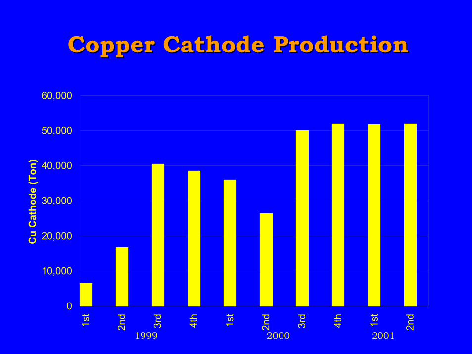
0
10,000
20,000
30,000
40,000
50,000
60,0001st
2nd
3rd
4th
1st
2nd
3rd
4th
1st
2nd
1999 2000 2001
Cu
Cat
ho
de
(To
n)
Copper Cathode ProductionCopper Cathode Production
ConclusionConclusion
• The designed yearly capacity willbe confirmed
• All the strict environmentalstandards are cleared
• Plant have been operated 100%by Indonesian staffs