Embed Size (px)
Citation preview
DEVELOPMENT OF METHODOLOGY TO QUANTIFY INSTALLATION DAMAGE ON
GEOTEXTILE FOR COASTAL APPLICATION
Charmaine Yi Ting Cheah BEng(Hons)
Submitted in fulfilment of the requirements for the degree of
Doctor of Philosophy
School of Civil Engineering and Built Environmental
Science and Engineering Faculty
Queensland University of Technology
2017

Development of methodology to quantify installation damage on geotextile for coastal application i
Keywords
Apparent Opening Size, CBR Puncture Resistant, Coastal Protection Structure, Drop
Rock Test, Filtration properties, Geosynthetics, Geotextiles, Hydraulic Efficiency,
Impact Resistance, Installation Damage, Pore Size, Retained Strength, Robustness,
Subgrade Moisture Content, Unsaturated Subgrade
ii Development of methodology to quantify installation damage on geotextile for coastal application
Publications
Published Peer Reviewed Journal Paper
Cheah, C., Gallage, C., Dawes, L., Kendall, P., 2016. Impact resistance and evaluation of retained strength on geotextiles. Geotextiles and Geomembranes 44, 549-556.
Cheah, C., Gallage, C., Dawes, L., Kendall, P., 2017. Measuring hydraulic properties
of geotextiles after installation damage. Geotextiles and Geomembranes 45, 462-470.
Journal Papers under Review
Cheah, C., Gallage, C., Dawes, L., Kendall, P., 2017. Investigating installation robustness of geotextile in relation to subgrade moisture condition. Geotextiles and Geomembranes (under review).
Published Peer Reviewed International Conference Papers
1. Kendall , P., Austin, R.A., Cheah , C., Lacey , M., 2014b. Large Scale Controlled Testing of Geotextile Puncture Resistance for Rock Impact, 10th International Conference on Geosynthetics. Deutsche Gesellschaft für Geotechnik e.V., Berlin Germany.
2. Kendall, P., Austin, R.A., Cheah, C., 2014a. Installation Durability Testing of Revetment Geotextiles, 7th International Congress on Environmental Geotechnics, Melbourne, Australia.
3. Cheah, C., Gallage, C., Dawes, L., Kendall, P., 2015. Effect of Simulated Rock Dumping on Geotextile, 12th Australia New Zealand Conference on Geomechanics, Wellington, New Zealand.
Development of methodology to quantify installation damage on geotextile for coastal application iii
Abstract
Since geotextiles have been progressively incorporated into coastal protection
structures, the influence of construction stress on geotextile has been the primary
concern. During the construction of coastal structures with geotextiles, rock dumping
(installation method) imparts high mechanical stress on the laid geotextiles. These
stresses can degrade geotextiles’ mechanical strength and filtration properties. This
puts the stability and performance of geotextiles in coastal structures at risk. Research
studies point out that the heavy construction stresses imparted onto the material usually
by far exceeds the service stresses. This suggests that the critical period of geotextile
is during installation/ construction process. Therefore, it is essential to assess and
estimate any change in mechanical and filtration properties of geotextiles upon
installation where construction stress (dropping rocks) is involved. Filtration
properties of geotextiles herein refer to as hydraulic performance of geotextiles’ in
terms of permittivity and pore size. Long term observational studies and case studies
are the core of the current design guideline. These approaches are highly accurate in
assessing the extent of damage (mechanical and filtration properties) on geotextiles
after installation, but it requires heavy logistics (man power and time).
To minimise damage during installation, designers and engineers depend on
specifying minimum geotextile properties and on-site performance testing. These
values are derived from mechanical index tests such as California Bearing Ratio (CBR)
test, Wide Strip Tensile Test (WSST), Trapezoidal Tear Test etc. Conventional
laboratory approaches are highly conservative in accounting for the stress state of the
geotextile material under real installation conditions due to an inadequate ability to
replicate the construction stress (rock dumping). On-site tests are accurate in reflecting
iv Development of methodology to quantify installation damage on geotextile for coastal application
the performances of geotextiles under real installation conditions but there are many
installation parameters that cannot be fully controlled to produce repeatable results.
Besides, each installation site has its own unique field conditions which make
comparison of results difficult. Drawbacks of both index and field trials in minimising
installation damage highlight a requirement for a new testing methodology.
Towards this aim, a new Drop Rock Test (DRT) method is developed in this
research to produce similar construction stress imparted in the field. Referring to the
method developed the performance such as retained strength and filtration properties
of geotextiles can be evaluated in conditions more closely aligned with what happens
in practise. A series of tests with different non-woven geotextiles, drop height, weight
of armour rocks and subgrade moisture content with this newly developed apparatus
showed that the index derived values do not primarily govern the robustness of
geotextile during installation. This research study showed that geotextiles with better
mechanical properties did not outperform lower mechanical strength geotextiles. This
further supports the correlation between index tests and field performance is empirical
in nature. This research analysed the retained strength and filtration properties of
geotextile on dry subgrade and found that there is a strength reduction, up to 50% upon
installation which is critical when considering coastal structures are designed to last
for 100 years.
Installation damages could affect the hydraulic efficiency of geotextiles or in the
severest form of damage, punctured (hole), would limit the filtration function. The
properties investigated in this study include the permittivity and apparent opening size
(AOS) of geotextiles. This study showed that the greater the drop energy of an armour
unit (a function of drop height and weight of an armour unit) applied to geotextiles,
the greater the potential for damage. Findings show that the residual permittivity

Development of methodology to quantify installation damage on geotextile for coastal application v
increase significantly, approximately 45% upon installation. Using these results, this
research developed design charts predicting permittivity of geotextiles after
installation.
To date, little research is available on the influence of site characteristics on the
robustness of geotextile during installation procedures. Moisture content, density and
soil type of the subgrade have significant effects on the installation damage of
geotextiles. The proposed DRT method was revised to replicate different subgrade
moisture content to examine the robustness of geotextiles under different installation
conditions (dry, field or saturated subgrade). Findings suggest dumping rock on
geotextiles on dry subgrades results in severe damage compared to saturated subgrade.
Considering data and findings into mechanical, filtration properties and site
characteristics, it can be concluded that the newly developed semi-laboratory method,
DRT in this research replicates construction stress in-situ realistically. With the use of
the DRT, the influence of construction stress and subgrade moisture content on the
robustness, mechanical and filtration properties of geotextiles can be examined. This
results in development of design charts. Engineers and designers would be able to use
the design charts to specify the appropriate geotextile that have sufficient robustness
to resist damage during construction which reduces risk and is cost-saving.
vi Development of methodology to quantify installation damage on geotextile for coastal application
Table of Contents
Keywords .................................................................................................................................. i
Publications .............................................................................................................................. ii
Abstract ................................................................................................................................... iii
Table of Contents .................................................................................................................... vi
Statement of Original Authorship ........................................................................................... ix
Acknowledgements .................................................................................................................. x
Chapter 1: Introduction............................................................................................. 1
1.1 Background ........................................................................................................................ 1
1.2 Aims and Objectives .......................................................................................................... 3
1.3 Scope .................................................................................................................................. 4
1.4 Significance of research ..................................................................................................... 5
1.5 Research Design ................................................................................................................. 6
1.6 Thesis Outline .................................................................................................................... 8
1.7 Linkage of scientific papers ............................................................................................... 8
Chapter 2: Literature Review ................................................................................. 11
2.1 Introduction ...................................................................................................................... 11
2.2 Geotextiles ........................................................................................................................ 14 2.2.1 Non-woven Geotextiles ....................................................................................... 14 2.2.2 Design and construction challenges .................................................................... 15 2.2.3 Selection of Geotextiles ...................................................................................... 16
2.3 Types of damages ............................................................................................................. 16
2.4 Previous research .............................................................................................................. 18
2.5 Existing Test Methods ...................................................................................................... 23 2.5.1 Index Test methods ............................................................................................. 23 2.5.2 Field Trials .......................................................................................................... 29
2.6 Summary .......................................................................................................................... 31
Chapter 3: Research Design .................................................................................... 35
3.1 Methodology .................................................................................................................... 35
3.2 Drop Rock Test ................................................................................................................ 37
3.3 Visual assessment ............................................................................................................. 42
3.4 Static Puncture Test .......................................................................................................... 43
3.5 Constant Head Test .......................................................................................................... 43
3.6 Bubble Point Test ............................................................................................................. 43
Chapter 4: Impact Resistance and evaluation of retained strength .................... 45
Statement of Contributions of Joint Authorship ..................................................................... 45
Linkage of paper to Research Methodology and Development ............................................. 46
Development of methodology to quantify installation damage on geotextile for coastal application vii
Abstract ...................................................................................................................................48
4.1 Introduction .......................................................................................................................48
4.2 Materials and Experimental Description ...........................................................................52 4.2.1 Drop Rock Test ....................................................................................................52 4.2.2 Materials ..............................................................................................................55 4.2.3 Static Puncture (CBR) Test .................................................................................57
4.3 Results and Discussion .....................................................................................................57 4.3.1 Impact Resistance ................................................................................................57 4.3.2 Retained Strength.................................................................................................62
4.4 Conclusion ........................................................................................................................65
Acknowledgements .................................................................................................................66
References ...............................................................................................................................66
Chapter 5: Measuring hydraulic properties of geotextiles after installation ..... 69
Statement of Contributions of Joint Authorship .....................................................................69
Linkage of paper to Research Methodology and Development ..............................................70
Abstract ...................................................................................................................................72
5.1 Introduction .......................................................................................................................72
5.2 Test Program .....................................................................................................................78 5.2.1 Materials ..............................................................................................................78 5.2.2 Equipment and Methodology...............................................................................79
5.3 Results and Discussion .....................................................................................................83 5.3.1 Permittivity ..........................................................................................................83 5.3.2 Retention ..............................................................................................................91 5.3.3 Strained/Elongation .............................................................................................93 5.3.4 Abrasion Damage ................................................................................................94
5.4 Limitations ........................................................................................................................95
5.5 Conclusion ........................................................................................................................95
Acknowledgements .................................................................................................................96
Notations .................................................................................................................................96
References ...............................................................................................................................97
Chapter 6: Investigation of installation robustness of geotextiles in relation to subgrade moisture condition ................................................................................... 99
Statement of Contributions of Joint Authorship .....................................................................99
Linkage of paper to Research Methodology and Development ............................................100
Abstract .................................................................................................................................102
6.1 Introduction .....................................................................................................................102
6.2 Materials and Experimental Description .........................................................................105 6.2.1 Drop Rock Test ..................................................................................................110 6.2.2 Static Puncture (CBR) test .................................................................................112 6.2.3 Materials and test program ................................................................................112
6.3 Results and Discussion ...................................................................................................113 6.3.1 Impact survivability of non-woven geotextiles .................................................113 6.3.2 CBR Puncture Strength ......................................................................................116
viii Development of methodology to quantify installation damage on geotextile for coastal application
6.4 Limitations ..................................................................................................................... 118
6.5 Conclusions .................................................................................................................... 118
Acknowledgements .............................................................................................................. 119
References ............................................................................................................................ 119
Chapter 7: Discussion ............................................................................................ 121
7.1 Introduction .................................................................................................................... 121
7.2 Major Outcomes ............................................................................................................. 122 7.2.1 Drop Rock Test Methodology (Objectives 1 and 2) ......................................... 122 7.2.2 Geotextiles’ robustness against construction stress (rock dumping)
(Objective 4) .................................................................................................... 123 7.2.3 Damage assessment (permittivity) upon installation (Objectives 2 and 5) ....... 125 7.2.4 Geotextiles’ robustness against subgrade moisture condition (Objective 3
and 6) ............................................................................................................... 127 7.2.5 Research Impact for other forms of geosynthetics .......................................... 129
Chapter 8: Conclusion ........................................................................................... 130
8.1 Conclusions .................................................................................................................... 130
8.2 Recommendation for future studies................................................................................ 133
Bibliography ........................................................................................................... 135

Development of methodology to quantify installation damage on geotextile for coastal application ix
Statement of Original Authorship
The work contained in this thesis has not been previously submitted to meet
requirements for an award at this or any other higher education institution. To the best
of my knowledge and belief, the thesis contains no material previously published or
written by another person except where due reference is made.
Signature:
Date: 27 September 2017
QUT Verified Signature
x Development of methodology to quantify installation damage on geotextile for coastal application
Acknowledgements
Completion of this Doctoral research would have not been possible without the support
and assistance of numerous people throughout the research project. I would like to
express my appreciation to my Principal Supervisor, Dr Chaminda Gallage, Associate
Supervisor, Prof Les Dawes and External Supervisor, Mr Preston Kendall. Their
support, guidance and professional advice provided to me throughout the duration of
the research has been invaluable and I am very grateful for their assistance.
I wish to acknowledge QUT Australian Postgraduate Awards (APA) (2014-
2016) and QUT Research Training Program (RTP) (2017) for providing scholarship
for this research study. I would also like to acknowledge the financial support, test
materials and testing facilities provided by Geofabrics Centre of Excellence in Gold
Coast, Australia. The support given by technical team, Mr. Dan Gibbs, Mr. Warren
Mitchell, Ms. Dawn Smith is gratefully acknowledged.
I would also like to express my appreciation to Texas Research Institute (TRI)
Australasia for providing the testing facility for the study of filtration properties of
damaged geotextiles and thank the technical staffs, particularly Mr. Warren Hornsey
and Miss Patricia Voussem for sharing insight and expertise that greatly assisted the
research.
To my colleagues, Mr Biyanvilage Dareeju and Mr Glen Barnes, I appreciate
them for their assistances and advices in conducting experimental studies on the
permittivity of geotextiles. Finally, the support given by QUT technical staffs and QUT
undergraduate students (Mr. Gerard Vink, Mr. Matthew Lacey, Mr. Lawrence Chai,
Mr. Oliver Iacopi, and Mr. Luke Blacklock) are gratefully acknowledged.
Introduction 1
Chapter 1: Introduction
1.1 Background
Geotextiles were first introduced as construction expedients for low risk civil
structures like transport applications. Parallel with the development of man-made
fabric, the multifaceted geotextiles have been incorporated in coastal protection
structures such as revetments and bund walls. Geotextiles act as filters and separators
as well as providing drainage and reinforcement for structural stability. Geotextiles
has progressively been incorporated into geotechnical applications especially coastal
protection structures like rock revetments and armoured bank (Heerten, 1984; Koerner,
2016a; Koerner, 1984; Mannsbart and Christopher, 1997; Nielsen et al., 2013;
Pilarczyk, 2000; Pilarczyk, 2003).
Geotextiles are incorporated into revetment armours, gabions and riprap to
prevent soil erosion. For coastal protection application, geotextiles have been
extensively used as filters where the material acts a filter layer between the rocks laid
above and subgrade beneath. The material has gradually substituted traditional
granular material as filter material because of their comparable function and consistent
properties. The installation technique for geotextile is also quicker and easier and more
labour efficient compared to placing granular material in position.
However, the material often suffers damage due to high dynamic bulk loading
of rock placements (construction stress), which may compromise the material’s
mechanical and filtration properties (Hornsey, 2012; Wong et al., 2000b). The long-
term performance of geotextiles depends on the retained properties upon installation.
Therefore, it is essential to examine the influence of construction stress (rock dumping)
on the physical, mechanical and filtration properties of geotextiles. The influence of
2 Chapter 1: Introduction
construction stress on geotextiles’ properties is yet to be sufficiently evaluated due to
the lack of an appropriate method to replicate installation conditions. As a result,
designers and engineers rely on long term observational studies (Heerten, 1984;
Heerten, 2007; Hsuan et al., 2008; Loke et al., 1995; Mannsbart and Christopher, 1997;
Watn and Chew, 2002; Wong et al., 2000a) to understand the mechanical and filtration
properties after installation. Knowledge of mechanical and filtration properties can be
identified and measured but these studies require high operational costs and time
(mostly in years).
The common methods adopted by engineers and designers when selecting
geotextiles (type and grade) to ensure installation damage resistance involve
specifying minimum mechanical properties and field trials. This often leads designers
and engineers specifying thicker geotextiles (higher cost) or adopting construction
method that is uneconomical and not efficient. Minimum mechanical properties are
usually specified from index tests so that the material for the intended function can be
selected. Though the current index based classification system is able to predict the
performance behaviour of geotextiles, it fails to take account of the site characteristics.
Consequently, the incorrect selection of material leads to poor on-site performance
(Giroud, 2000, 2005; Heerten, 2007; Koerner and Koerner, 2015). Authors presented
sixty-nine (69) case studies related to inadequate performance of geotextile filter after
installation due to inadequate design, atypical soils, unusual permeants and improper
installation (Koerner and Koerner, 2015). Although Lawson established a strong
correlation between index tests and performance on site, the relationship is still
empirical in nature (Lawson, 1992). It is difficult and risky to rely on minimum
specified index values as installation sites have various parameters influencing the
materials’ resistance to damage. Hence, many experimental studies and research

Introduction 3
constantly review and revise existing design guidelines and standards (Briaud, 2013;
Christopher and Fischer, 1992; Koerner, 2016b; Loke et al., 1995; Luettich et al., 1992;
Pilarczyk, 2003; Rawal et al., 2010b).
Field trials provide accurate results, but currently, there isn’t a standard
procedure for on-site testing that is adopted by the industry. This is because procedures
in conducting performance test on-site varies in many ways and is influenced by many
factors including geotextile characteristics, height and weight of released armour rock
and characteristics of soil base. Given that each installation/construction site has
distinct environmental features, makes it even harder to develop a standard procedure
that is adoptable for different construction sites. These field/ on-site performance tests
are subjected to high operation costs, undergo difficulties in controlling site
characteristics and comparing results. These limitations highlight a requirement for a
new experimental approach to evaluate the influence of construction stress on the
behaviour of physical, mechanical and filtration of installed geotextiles. Development
of a new methodology to evaluate the robustness of geotextiles during installation is
therefore promising to the designers and engineers from both designing, construction
and maintenance perspectives, in providing a stable coastal protection structure.
Robustness herein refers to geotextiles’ or ability to survive (without puncturing)
under impact loads that are applied by dropping rocks onto geotextiles laid on the
subgrades or resist damage during installation (no perforation holes).
1.2 Aims and Objectives
The main aim of this research is to develop a new experimental methodology to
examine the influence of construction stress (rock dumping) on geotextiles’
robustness, mechanical strength and filtration properties in coastal protection
structures. The study also examines the influence of subgrade characteristics on

4 Chapter 1: Introduction
geotextiles’ robustness. The aims of the research are achieved through the following
objectives:
1. Develop new experimental method to replicate construction stress (rock
dumping) on geotextiles for coastal application
2. Examine the influence of construction stress on geotextiles properties
(robustness, mechanical strength, physical and filtration)
3. Examine the influence of subgrade characteristics (i.e. moisture condition) on
geotextiles’ robustness during installation
4. Develop design chart to predict robustness of geotextile during installation
5. Develop design chart to predict the hydraulic/ filtration performance
(permittivity) after installation
6. Develop chart for robustness of geotextile against subgrade moisture condition
1.3 Scope
The research undertaken was specifically focused around installation damage
associated with construction stress (rock dumping) on geotextiles. The influence of
construction stress and site characteristics on the robustness, mechanical and filtration
properties of geotextiles upon installation were investigated. The study was confined
to non-woven geotextiles (staple fibre and continuous filament) as they are commonly
used with coastal protection structures. Note that non-woven geotextiles are just one
part of a geosynthetics group that are often constructed to support various civil
applications. Geosynthetic material such as woven geotextile, geogrids,
geomembranes, geosynthetic clay liner and geo-composites are not considered in this
study.
The focus of this research was to examine the influence of construction stress on
the short term performance (robustness, retained strength, permittivity and pore size)
Introduction 5
of geotextiles. Long term performance related to the resistance to degradation of
geotextiles installed (clogging, thermal sensitivity, chemical and oxidation resistance,
weathering) were not investigated. The testing method, Drop Rock Test (DRT) was
developed to replicate construction stress, i.e. dumping rock on geotextiles laid on
subgrade during construction of coastal protection structures. The outcomes are
applicable to comparable drop heights and weight of armour rocks in similar field
settings.
Construction of coastal revetment is commonly conducted on natural sand that
could either be dry, semi-dry/wet (field) or saturated condition. An investigation of
robustness in relation to subgrade moisture condition provides relevant information
for site conditions which can have varying levels of moisture depending on the tidal
influence and the climate.
1.4 Significance of research
The lack of methodology to simulate construction stress for coastal application works
has led to the need for developing a new experimental method that would provide
similar nature and extent of damage on geotextiles as the construction process. The
benefit of using the developed method to examine the influence of construction stress
on geotextiles would reduce the underestimation or overestimation of the performance
of geotextiles. This will give engineers and designers greater confidence in selecting
the appropriate geotextile for a given function. The outcomes would be developed
charts to predict the robustness, retained strength and the filtration properties of
geotextiles during installation (rock dumping) process.
The introduced method provides adequate information to help engineers to choose
appropriate geotextile that have sufficient robustness to resist damage during
6 Chapter 1: Introduction
construction and is cost effective. Designers and engineers would save cost as the
appropriate geotextile and construction method are selected (i.e weight of armour
rocks and height of released stone). The stability of the finished coastal structure will
be maximised as the extent of damage on geotextile during construction is minimised.
1.5 Research Design
Figure 1 illustrates the research process in the form of a flow chart. The initial phase
of the study focuses on the research literature and identifying knowledge gaps to
establish the research problem. The outcomes from experimental investigations
provide a scientific basis for assessing the short term performance (robustness, retained
strength, and filtration properties) of geotextile. As a result of detailed data analysis,
identification of threshold drop energy, analysis of retained strength, residual
permittivity and pore size of geotextile, robustness and damage assessment for
permittivity charts for non-woven geotextiles were developed.

Introduction 7
Figure 1-1: Flow chart of research process (Refer specific objectives in Chapter 1.2)
Investigate coastal protection structure with geotextiles
Selection of geotextiles for study
Evaluate existing methods that evaluates geotextiles' robustness against construction (rock dumping)
Examine the influence of construction stress (rock dumping) on mechanical and filtration properties
Development of testing methodology
Quantify and assess the influence of construction stress on geotextiles' robustness and retained strength
Analysis of construction stress on the filtration properties of geotextiles
Examine the influence of site characteristics on geotextiles' robustness and retained strength
Develop design chart for robustness of geotextiles against construction stress using Drop and CBR energy
Develop design chart to predict the permittivity performance of geotextile upon instllation
Develop charts to predict robustness of geotextiles against subgrade moisture condition
Lite
ratu
re a
nd D
eskt
op S
tudy
E
xper
imen
tal a
nd D
ata
Ana
lysi
s R
esea
rch
Out
com
es
Journal Paper 1 - Obj. 1 - Obj. 2
Journal Paper 2 -Obj. 2 -Obj. 5
Journal Paper 3 -Obj. 1 -Obj. 3 -Obj. 6
Con
f. P
aper
2
-O
bj. 4
8 Chapter 1: Introduction
1.6 Thesis Outline
This thesis consists of eight chapters. Chapter 1 presents the research background,
development of research problem, aim and objectives to address the research problem,
significance and scope of this study. Chapter 1 also illustrates the research design
process and presents the linkage of scientific papers. The relevant research literature
and knowledge gaps are summarised in Chapter 2. It highlights the types of non-woven
geotextiles, the challenges faced when designing geotextiles with coastal protection
structures and the types of damages geotextiles are subjected during installation
process. Chapter 3 describes the testing methodology developed, index tests that were
used in this study and mechanical properties of non-woven geotextiles tested. Chapter
4 and 5 in the form of peer reviewed papers examines the influence of construction
stress on geotextiles’ robustness, mechanical and filtration properties. Likewise
Chapter 6 describes the influence of subgrade moisture conditions on the robustness
of geotextile. The major findings from Chapter 4, 5 and 6 are discussed in Chapter 7,
along with the development of methodology, design charts and guidelines for
geotextiles’ robustness and permittivity. Chapter 8 finally concludes the research and
significant findings along with recommendations for future research.
1.7 Linkage of scientific papers
The central focus regarding the design of coastal protection structure with geotextiles
is the robustness (survivability) of the material during installation/construction
process. The effects of construction stress (installation method-dumping rock on
geotextiles) on geotextiles play a vital role in determine the short-term performance
(retained strength and hydraulic properties) of geotextiles in the structure. Currently
there is no index test method that could account for field conditions (drop height,
weight of rock and subgrade condition) that determines the survivability (robustness)
Introduction 9
of the material and any assessment study that focus directly on the influence of
construction stress on the mechanical and hydraulic performance of geotextile.
Chapter 4, Paper 1 (Impact resistance and evaluation of retained strength)
investigates and identifies the advantages and disadvantages of the current methods
(index tests and field trials) to assess the survivability of the geotextile during
installation/construction process. The paper also describes the use of a new
methodology, Drop Rock Test (DRT) to replicate construction stress on geotextile and
assesses the influence of rock dumping on the mechanical performance of geotextile
with static puncture CBR test.
Chapter 5, Paper 2 (Measuring hydraulic properties of geotextile after
installation) investigates the influence of construction stresses (rock dumping) on the
filtration properties of geotextiles. Non-woven geotextiles were submitted to damage
–through DRT test and further assessed with laboratory tests (Constant Head test and
Bubble Point Test). Findings suggest the filtration properties of severely damaged
specimen still meet the permittivity and retention criterion.
Both papers (1 and 2) discuss the mechanical strength and hydraulic properties
after induced damage test (Drop Rock Test), but the influence of site characteristics
on the robustness (survivability) of geotextile during installation have not been
investigated. Chapter 6, Paper 3 (Methodology to investigate installation robustness
of geotextile in relation to subgrade condition) contributes to a better understanding
of how subgrade moisture condition (dry, field, and saturated) can affect the robustness
of geotextile during installation process. The study suggests that damage found on
installed geotextile is more severe in the case of dry subgrade than in the case of field
and saturated subgrade.
10 Chapter 1: Introduction
Together Papers 1, 2 and 3 examined the mechanical and hydraulic influence of rock
drop installation on geotextile and identified the threshold drop energy during
installation for the relevant grade of geotextiles. The combined outcomes from Papers
1, 2 and 3 provided a scientific basis for assessing the short term performance of
installed geotextile via DRT. As a result of detailed evaluation of the laboratory testing
and data analysis, identification of threshold drop energy, analysis of retained strength,
residual permittivity and pore size of geotextile, damage assessment methods and
design charts were developed. Findings confirmed that Drop Rock Test can
realistically replicate installation conditions which include construction stress of an
armour rock dumped onto geotextiles and moisture condition of subgrade. DRT can
replicate construction stress by varying the drop energies of released armour rock
(concrete block). The varying moisture condition of subgrade can be achieved by
adding different moisture content into the subgrade. DRT is a realistic and practical
methodology to assess the robustness of geotextile during installation. Index tests
(CBR puncture, Constant Head, Bubble Point) were used to further assess the influence
of installation conditions (release of armour rocks and subgrade moisture condition)
on the mechanical and hydraulic performance of geotextile. The combined used of
DRT and index tests provided a more reliable approach to predict the short-term
behaviour of geotextile during installation. The outcomes of this research includes
the development of design charts for geotextiles’ robustness against construction stress
for non-woven geotextiles, design charts for geotextiles’ damage assessment for
permittivity behaviour upon installation and charts of robustness against subgrade
moisture condition for non-woven geotextiles.
Literature Review 11
Chapter 2: Literature Review
2.1 Introduction
Coastal erosion is one of the common problems in coastal and marine developments.
It is often caused by sea level changes (rise/fall), extreme weather events (severe
storms, tides and winds), human activities and natural evolutionary phenomena. Shore
or bank protection structures use either armour rocks, rip raps or gabions to dissipate
water and tidal currents that would naturally induce erosion (Abromeit and Heibaum,
1996). To prevent coastal erosion, granular layers are placed beneath revetments,
overlaid with armour rocks/stone. The main objective is to protect and prevent the base
soil from eroding by layering granular filter materials beneath the primary armour
units. Besides achieving the main objective, the structure needs to be hydraulically
stable which requires the granular filters to have particle sizes that are both small
enough to prevent erosion of the base soil and large enough to prevent erosion of the
granular material itself through the m ore porous layer above. However due to the cost
and construction difficulties (construction below water level), revetments with
granular layers often fail to be constructed in a systematic manner (featuring four
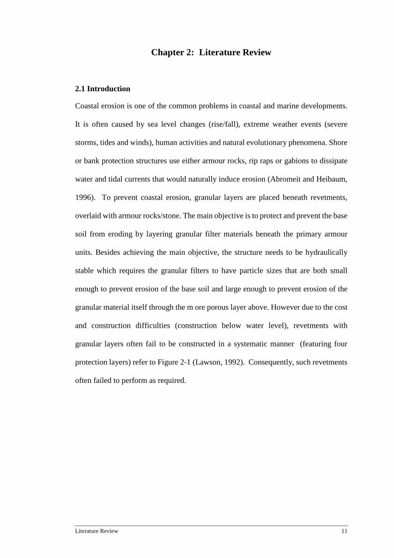
protection layers) refer to Figure 2-1 (Lawson, 1992). Consequently, such revetments
often failed to perform as required.
12 Chapter 2: Literature Review
Figure 2-1: Revetment consisting wholly of granular materials (Lawson, 1992)
Figure 2-2: Revetment containing geotextile filter(Lawson, 1992)
Parallel with man-made development, geotextiles have gradually incorporated into
coastal protection structures, such as rip-rap revetments and armoured banks, refer to
Figure 2-2. Like granular filters, geotextiles act as filter and separator. They have
quick installation technique and less labour requirements compared to placing granular
filters in position. Their comparable function and consistent material properties have
naturally replaced the conventional granular material as filter beneath armour units.
Over the last 40 years, geotextiles have served successfully as separators and filters in
Literature Review 13
coastal protection structures(Loke et al., 1995). Despite the large number of successful
applications, there are examples where geotextiles fail to functions as required due to
damage during installation. Most geotextiles-related failures were reported to either
construction or design –related and are generally caused by (Kumar Shukla and Yin,
2006):
• Loss of strength due to UV exposure
• Lack of proper overlay
• High installation stresses.
The installation of geotextiles involves the bulk loading of primary armours above
geotextiles. This construction method maybe fast, but brings with it a high risk of
puncturing the geotextile if an inappropriate geotextile was selected and/or improper
selection weight of armour rock to release from too high a height. This mechanical
action imparts high installation/construction stresses onto the continuous sheet
material. Damage from the mechanical impact on the geotextile filters could easily
degrade their mechanical strength and filtration properties. Proper construction and
installation techniques are crucial in order to ensure that the intended functions of the
geotextiles are fulfilled. Hence, the installation of geotextile is thus the most important
step in governing the success or failure in the performance of coastal structure with
geotextiles.
This chapter describes the commonly used geotextiles for coastal erosion
protection structures and the types of damage mechanisms related to mechanical
impact and filtration properties during installation in the construction process. The key
challenges and the relevant testing methods dealing with geotextiles’ robustness,
14 Chapter 2: Literature Review
including past investigations and studies evaluating the mechanical and filtration
properties of geotextiles after installation are reviewed
2.2 Geotextiles
Over the last 40 years, geotextiles have been extensively incorporated into these
revetments because of their cost-effectiveness, ease of installation, consistent material
properties (Giroud, 1984; Lawson, 1982; Palmeira et al., 2008). This material could
be manufactured either in woven or non-woven form. Woven geotextiles are made of
fibres manufactured in two perpendicular directions, one over the other. Non-woven
geotextiles are manufactured in random distribution manner (Bhatia and Smith, 1996).
These geotextiles are generally made from synthetic fibres such as polypropylene (PP),
polyester (PET), polyamide (nylon) or polyethylene (PE). Woven geotextiles have
higher strengths in machine direction and lower elongation properties. On the contrary,
non-woven geotextiles have lower mechanical strength with better elongation
properties than woven geotextiles (Raumann, 1982). Though woven geotextiles have
higher mechanical strength, its weak elongation properties hinder its’ ability to
conform to uneven shapes of armour units and elongate when forced is applied.
Therefore, non-woven geotextiles will only be considered for this research work.
2.2.1 Non-woven Geotextiles
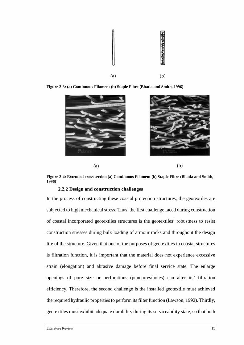
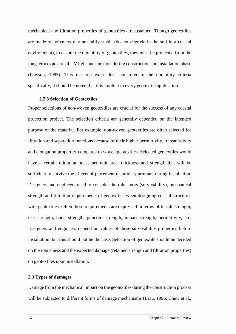
There are two types on non-woven geotextiles, namely continuous filaments, and
staple fibres (Fig. 2-2). Both nonwovens are made from continuous extruded circular
cross section filament (Fig. 2-3) and the only distinct trait between them is the length
of the fibres. Continuous filaments are comparatively longer in length in contrast to
the short staple fibres which length ranges from 25-100mm(Bhatia and Smith, 1996).
Literature Review 15
(a)
(b)
Figure 2-3: (a) Continuous Filament (b) Staple Fibre (Bhatia and Smith, 1996)
(a)
(b)
Figure 2-4: Extruded cross section (a) Continuous Filament (b) Staple Fibre (Bhatia and Smith, 1996)
2.2.2 Design and construction challenges
In the process of constructing these coastal protection structures, the geotextiles are
subjected to high mechanical stress. Thus, the first challenge faced during construction
of coastal incorporated geotextiles structures is the geotextiles’ robustness to resist
construction stresses during bulk loading of armour rocks and throughout the design
life of the structure. Given that one of the purposes of geotextiles in coastal structures
is filtration function, it is important that the material does not experience excessive
strain (elongation) and abrasive damage before final service state. The enlarge
openings of pore size or perforations (punctures/holes) can alter its’ filtration
efficiency. Therefore, the second challenge is the installed geotextile must achieved
the required hydraulic properties to perform its filter function (Lawson, 1992). Thirdly,
geotextiles must exhibit adequate durability during its serviceability state, so that both
16 Chapter 2: Literature Review
mechanical and filtration properties of geotextiles are sustained. Though geotextiles
are made of polymers that are fairly stable (do not degrade in the soil in a coastal
environment), to ensure the durability of geotextiles, they must be protected from the
long term exposure of UV light and abrasion during construction and installation phase
(Lawson, 1983). This research work does not refer to the durability criteria
specifically, it should be noted that it is implicit to every geotextile application.
2.2.3 Selection of Geotextiles
Proper selections of non-woven geotextiles are crucial for the success of any coastal
protection project. The selection criteria are generally depended on the intended
purpose of the material. For example, non-woven geotextiles are often selected for
filtration and separation functions because of their higher permittivity, transmissivity
and elongation properties compared to woven geotextiles. Selected geotextiles would
have a certain minimum mass per unit area, thickness and strength that will be
sufficient to survive the effects of placement of primary armours during installation.
Designers and engineers need to consider the robustness (survivability), mechanical
strength and filtration requirements of geotextiles when designing coastal structures
with geotextiles. Often these requirements are expressed in terms of tensile strength,
tear strength, burst strength, puncture strength, impact strength, permittivity, etc.
Designers and engineers depend on values of these survivability properties before
installation, but this should not be the case. Selection of geotextile should be decided
on the robustness and the expected damage (retained strength and filtration properties)
on geotextiles upon installation.
2.3 Types of damages
Damage from the mechanical impact on the geotextiles during the construction process
will be subjected to different forms of damage mechanisms (Bräu, 1996; Chew et al.,

Literature Review 17
1999; Watn and Chew, 2002; Wong et al., 2000a; Wong et al., 2000b). There are four
common damage mechanisms that typically occur during the installation phase, these
are tensile strained (elongation), abrasion, tearing and puncturing. Tensile strained is
the result of geotextiles elongating to conform to the uneven shape of armour rock
during installation and operational phase. The physical change in length could
significantly affect the pore size and permittivity of the material, consequently,
affecting its filtration efficiency.
Abrasive shearing is the result of sliding friction between geotextile and
subgrade caused by the falling of rock amour during installation. This type of damage
is noted on the subgrade-geotextile interface where the fibrous layers of the material
are sheared away during the sliding motion of the armour rocks which results in
thinning of the material. Research show that severe abrasion by sharp particles (quartz
sand, max diameter 200µm) leads up to 50% strength reduction (Watn and Chew,
2002) and possibly affecting its’ filtration properties. Tearing is typically a result of
harsh installation and construction procedure; the multiple armour rocks released (bulk
loading) at the same time leads to a tear propagation that could degrade both the
mechanical and hydraulic performance of the material.
Puncturing damage is likely to occur when sharp edged amour units are dumped
directly on the geotextile filter. These armour rocks will penetrate the geotextile and
could compromise the separation and filtration efficiency (Watn and Chew, 2002).
However, research work by( (Chew et al., 1999; Lawson, 1992) found that the
puncturing damage in geotextile filter did not result in failure of the coastal structure,
as the armour rocks will seal the punctured hole, thus preventing soil loss. While
puncture damage may not govern the failure mode of the structure, from the viewpoint
of geotextile design and specification, it is important to minimise, or prevent
18 Chapter 2: Literature Review
puncturing of the geotextile. Authors (Christopher and Fischer, 1992; Heerten, 2007)
strongly imply that any geotextile application would be deemed pointless if the
material was damaged during construction phase. This justifies the need to examine
geotextiles’ extent of damage caused by the placement of armour rocks on geotextile
during construction process.
2.4 Previous research
Because geotextiles are prone to installation damage, it is essential to investigate the
extent of damage in terms of ability to fulfil its intended function in the structure after
installation, therefore, research have been ongoing since 1980s ((Bräu, 1996;
Christopher, 1983; Heerten, 1984; Heerten, 2007; Hornsey, 2012; Watn and Chew,
2002; Wong et al., 2000b). These studies suggest that the high dynamic stresses lead
to physical changes (strain/elongation) which affects the geotextiles’ mechanical and
filtration properties. Christopher (1983) evaluated the performance of woven
geotextile in a rip-rap revetment type seawall at the 70th Street Causeway Project in
Miami, Florida that was installed over a decade. Test results indicated a strength
reduction in the excavated geotextiles ranging from 5 to 40% reduction compared to
new manufactured material. The permeability of excavated geotextiles was 2 x 10-
3cm/s which is a 50% reduction in comparison with the new fabric. Despite the
mechanical damage, the installed material still managed to perform its intended
filtration function.
Mannsbart and Christopher (1997) evaluated the mechanical and filtration
properties of excavated geotextiles at sites across Europe and Malaysia that were
installed for 6-14 years. Their investigation showed a reduction in permeability and
mechanical strength compared to clean geotextile. The theoretical assumption is that
the permeability of the material would increase as it is subjected to tensile strain to

Literature Review 19
conform to the uneven shape of armour rocks. But permeability of the material was
found to be reduced. This could be correlated into two possible factors, either
environmental deposits or fibre re-orientation. Environmental deposits could obstruct
drainage path and hinder its filtration efficiency. The continuity of pores (width and
depth of pores) is affected by the re-alignment of fibres (tensile strain) during
installation. The discontinuity of pores (width and depth of pores) would greatly
influences the filtration efficiency of geotextiles (Rawal et al., 2010a) .
Research by Loke et al. (1995) presented the results of a field investigation of
non-woven geotextile filter in coastal protections works for marine clays that had been
in service for more than 5 years. Two coastal revetment structures were constructed
under two different environmental conditions: site A, geotextile was laid above the
marine clay and a layer of sand and at site B, geotextile was directly laid over the
marine clay. Excavated samples (unclean) at both sites had great reduction in
permeability, ranging from 40-70%. Interestingly, excavated samples (unclean and
clean) at site B have some contrasting results. The permeability of excavated-unclean
samples was reduced by 42% while permeability of excavated-clean samples increased
up to 60%.
This possibly suggests that the difference in permeability is caused by the
deposition of particles, sediments, organic matter as well as salt deposition, mineral
precipitation and bacterial growth in exhumed excavated-unclean samples. These
deposits obstruct and clog the drainage path and decrease the permeability of the
material. The study also recorded a significant reduction in puncture resistance,
approximately, 40% at site A. The study also noted the importance of tensile strain/
elongation of geotextiles as a key design requirement to ensure the ability of the
geotextile to conform to the armour rocks and achieve close contact between soil
20 Chapter 2: Literature Review
profile and primary armours (Loke et al., 1995). It is essential to achieve tight
interfaces as this helps to minimise the loss of the subsoil beneath the geotextile which
may results in structure instability.
A detailed investigation on the performance of woven geotextiles in a reclaimed
project located in the south-western coast in Singapore that had been in service for 12
years at the time of excavation evaluated the degradation of mechanical and filtration
properties (Wong et al., 2000a). The observed permeability of excavated geotextiles
(dirty and cleaned) increased which is in contrast with the previous case studies. The
increased in permeability agrees with the theoretical assumption; it is assumed that the
permeability of geotextile filter would increase as pore size would increase since the
material is subjected to tensile strain to conform to the uneven rock armour rocks.
Thus, pore size of geotextile filters would be enlarged resulting in greater permeability.
The decrease in permeability found in excavated samples in previous studies appears
to be influenced by the salt deposition, mineral precipitation, organic deposits and
bacterial growth (Rollin and Lombard, 1988). This is agreement with previous
research (Loke et al., 1995) where these environmental deposits were found to likely
to obstruct and clog the drainage path, and decrease the permeability of excavated
samples.
Undoubtedly, the results gathered from these case studies give engineers and
designers better confidence to select the appropriate geotextile based on the degree of
damage of geotextiles that were investigated. But these research studies require large
setup, is time consuming (mostly requires time in years) and costly because specimens
need to be assessed after several installation years. Watn and Chew (2002) and
Diederich (2000) point out that the heavy construction stresses imparted onto the
material usually by far exceeds the service stresses. This suggests that the critical
Literature Review 21
period of geotextile is during installation/ construction process. Though past studies
accurately measure the extent of damage on geotextiles but these investigations are
conducted after several installation years. The additional damages imparted on
geotextiles by wave attacks, in-service stresses, and environmental deposits act in a
collective manner; the direct influence of construction stress on the extent of damage
on geotextiles cannot determined.
The role of site characteristics in geotextiles’ robustness during installation has
not received much attention as it is often difficult to characterize the variability
(subgrade type, density and moisture content) in detail. Research suggests that
subgrade characteristic and properties often play a critical and complex role in
geotextiles’ robustness on-site (Abu-Farsakh et al., 2007; Chew et al., 1999; Lopes et
al., 2001). Investigations led by Wong et al. (2000b) concluded that density of
subgrade is crucial in the occurrence of punctures and holes on the geotextile. Results
suggest that for the same geotextile and at the same drop height, severe damage is
found in the case of dense sand subgrade than in the case of loose sand subgrade.
Though Wong et al. (2000b) considered the type and density of subgrade, but they
have not considered subgrade moisture content as a parameter to measure geotextiles’
robustness.
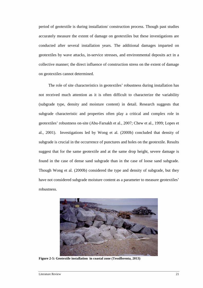
Figure 2-5: Geotextile installation in coastal zone (Tessilbrenta, 2013)
22 Chapter 2: Literature Review
Figure 2-5 illustrates an armour revetment in a coastal zone. Construction of revetment
structures could occur in fully dried, under water, or in partially saturated subgrade.
The question arises that under what circumstances the susceptibility of damage on
geotextile is lesser, saturated, unsaturated, or dry subgrade condition? To answer this
question, the study of geotextiles’ robustness against mechanical stresses should
consider the moisture condition. An evaluation of geotextiles’ robustness in relation to
subgrade moisture condition provides relevant information for site characteristics
which can have varying levels of moisture content depending on the tide and climate.
Summary key findings:
• Long term observational studies are conducted to determine the extent of
damage
• Both mechanical and filtration properties are affected after installation
• Case studies and research investigations are time consuming (mostly in
years), requires large setup and costly
• Difficult to isolate the influence of installation/construction stress on
geotextile from other damage factors
• Installation/ construction stresses (rock dumping) imparts the highest
mechanical impact
Identified knowledge gaps:
• Limited knowledge on the direct influence of rock dumping on geotextile
during installation
• Limited knowledge on the influence of subgrade moisture condition on
geotextiles’ robustness (survivability) during installation
Literature Review 23
• There is a need to develop a damage assessment chart to predict filtration
properties after installation. This would reduce the need to carry out large
scale and long term observational studies
2.5 Existing Test Methods
2.5.1 Index Test methods
The key factor ensuring geotextile filters continue to perform their intended function
after installation is geotextiles’ robustness to resist the perforation of armour rocks
during installation. To determine the robustness of geotextile for installation
procedures has led many attempts to develop appropriate laboratory test methods. The
geotextiles’ ability to resist these loads without damage must be proved. When placing
primary armour the geotextiles are subjected to dynamic perforation loads (rock
dumping influence by
- The shape and weight of stones
- Drop height of stones
- Strength of subgrade
- Placing in the dry or under water
To ensure installation damage resistance, minimum mechanical properties are usually
specified so that the material for the intended function can be selected; an example is
illustrated in Figure 2-6.
24 Chapter 2: Literature Review
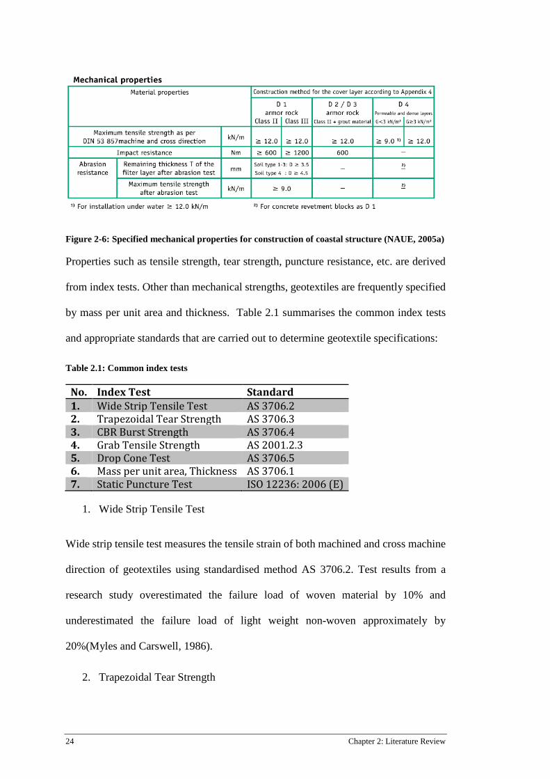
Figure 2-6: Specified mechanical properties for construction of coastal structure (NAUE, 2005a)
Properties such as tensile strength, tear strength, puncture resistance, etc. are derived
from index tests. Other than mechanical strengths, geotextiles are frequently specified
by mass per unit area and thickness. Table 2.1 summarises the common index tests
and appropriate standards that are carried out to determine geotextile specifications:
Table 2.1: Common index tests
No. Index Test Standard 1. Wide Strip Tensile Test AS 3706.2 2. Trapezoidal Tear Strength AS 3706.3 3. CBR Burst Strength AS 3706.4 4. Grab Tensile Strength AS 2001.2.3 5. Drop Cone Test AS 3706.5 6. Mass per unit area, Thickness AS 3706.1 7. Static Puncture Test ISO 12236: 2006 (E)
1. Wide Strip Tensile Test
Wide strip tensile test measures the tensile strain of both machined and cross machine
direction of geotextiles using standardised method AS 3706.2. Test results from a
research study overestimated the failure load of woven material by 10% and
underestimated the failure load of light weight non-woven approximately by
20%(Myles and Carswell, 1986).
2. Trapezoidal Tear Strength

Literature Review 25
The trapezoidal tear strength of material can be conducted according to AS 3706.3.
This test measures the force required to propagate a tear in geotextiles once a tear has
been initiated (in both machined and cross machined direction) by trapezoid method.
As this test shows little correlation with field performance, this test is no longer applied
and has been removed from the European standards (Watn and Chew, 2002).
3. CBR Burst Strength
The burst strength is measured by applying a normal pressure against a geotextile
sample secured in a ring. The stress against the geotextile at failure gives the value of
the bursting strength. The burst strength represents the strength of individual fibres in
geotextiles.
4. Grab tensile strength
The grab strength test is performed to ensure both the Quality Control (QC) and
Quality Assurance (QA) is achieved for geotextiles of similar structures(Sarsby and
Textile, 2007). Investigation reveals that grab tensile strength has no correlations with
geotextiles’ resistance to damage (Christopher and Elias, 1998).
5. Drop Cone test
Drop cone test is carried according to AS 3706.5 and quantifies the resistance of
geotextiles against damage by measuring the amount of damage by an impact force of
a cone shape object. Lawson’s studies implied the results obtained from the drop cone
test best represents the mechanical stress on geotextile (Lawson, 1992). However, the
accuracy of this research study is limited to geotextiles ranging in weight from 120-
300g/m2, which is too narrow when geotextiles used for coastal protection structures
generally ranges from 300 to 1200 g/m2. Despite this limitation, Lawson developed a
modified version of the drop cone test to accommodate the full range of geotextiles.
26 Chapter 2: Literature Review
However, despite the modification made, this test does not take into account the
installation conditions, for example, strength of subgrade (density) or the moisture
content of subgrade (placing in the dry or under water).
6. Mass per unit area, thickness
Mass per unit area is used as a characteristic relative value that is often correlated with
properties such as tensile strength, tear strength, puncture strength etc. The
heavyweight geotextile with a higher mass per unit area will usually be stronger than
a lightweight geotextile. Mass of geotextiles represents the amount of polymer used in
manufacturing of the product. Mass has been commonly used as an indicator for
mechanical performance but studies suggest that it is does not necessarily reflect
geotextiles’ robustness. Modernised manufacturing techniques with rapid
technological developments and better-quality raw materials could result in better
performing geotextile given the same amount of mass (Palmeira et al., 2008; Wong et
al., 2000b).
The thickness of geotextiles is required in the calculation of filtration properties
such as the permittivity and transmissivity. Correlation to index tests study found that
both mass per unit area and thickness are merely descriptive properties (Christopher
and Elias, 1998) and do not necessarily reflect the performance on-site when
comparing geotextiles of different structures, for example staple fibre and continuous
filament non-woven geotextiles.
7. Static Puncture Test
Test was developed to measure the puncture resistance of geotextiles (ISO 12236:
2006) using a flat end CBR plunger. The use of flat end plunger does not replicate the
same nature and extent of damage during installation. Besides, the applied energy was
Literature Review 27
static with plunger advancing at rate of 50 mm/minute; this does not reflect the
dynamic impact of armour units imparted on the geotextiles.
These index tests do not consider installation conditions which limits the
accuracy in assessing geotextiles’ field performance. For example, Static Puncture
Test is carried under static load conditions, whilst mechanical actions of primary
armours placement (bulk loading) are dynamic in nature. Despite that fact, industry
designers and engineers depend on specifying minimum mechanical properties and
mass per unit area to minimise the risk of puncture taking place on the laid geotextile
layer. This is a commonly adopted approach by the industry which could lead to
incorrect selection of geotextiles(Hornsey, 2012) .
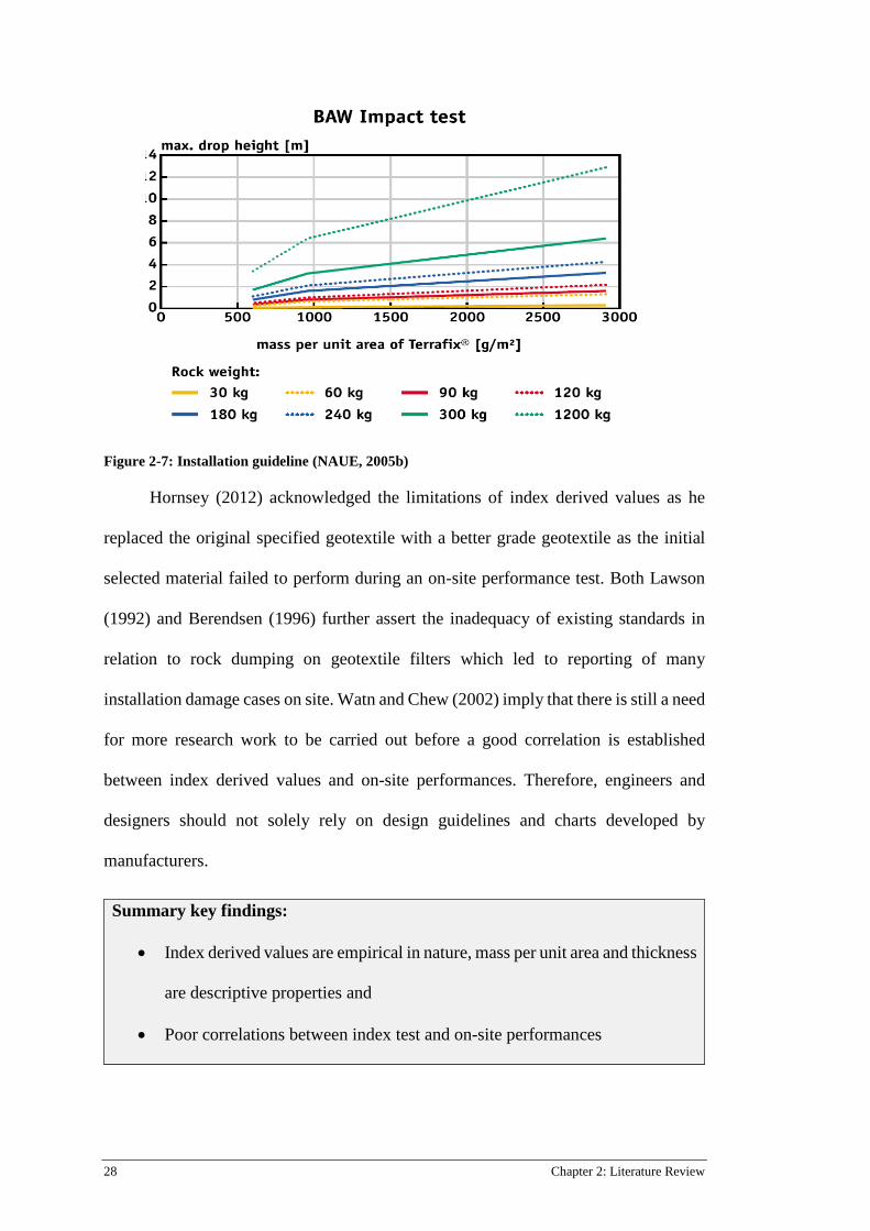
At present, the only laboratory test that replicates the dynamic impact of falling
armours on geosynthetics is developed by BAW in 1978 (current issue: RPG (1994) ).
This test replicates the dynamic impact by releasing a drop of hammer with a tip edge
onto the geotextile that is laid above a soil sample at determined drop energy
(Heibaum, 2014). Figure 2-7 illustrates the installation guideline referring to drop
height and mass per unit area of geotextiles using the BAW impact test. Though this
is a functional and versatile approach in assessing geotextiles’ robustness, the question
of the suitability of cylindrical drop hammer to represent armour units still invites
contention. A simplified chart with the use of drop energy as a function of rock mass
and drop height should be developed to represent the installation conditions.
28 Chapter 2: Literature Review
Figure 2-7: Installation guideline (NAUE, 2005b)
Hornsey (2012) acknowledged the limitations of index derived values as he
replaced the original specified geotextile with a better grade geotextile as the initial
selected material failed to perform during an on-site performance test. Both Lawson
(1992) and Berendsen (1996) further assert the inadequacy of existing standards in
relation to rock dumping on geotextile filters which led to reporting of many
installation damage cases on site. Watn and Chew (2002) imply that there is still a need
for more research work to be carried out before a good correlation is established
between index derived values and on-site performances. Therefore, engineers and
designers should not solely rely on design guidelines and charts developed by
manufacturers.
Summary key findings:
• Index derived values are empirical in nature, mass per unit area and thickness
are descriptive properties and
• Poor correlations between index test and on-site performances
Literature Review 29
Identified knowledge gaps:
• There is a requirement of a new method to replicate construction stress (rock
dumping) to determine geotextiles’ robustness against mechanical stress
2.5.2 Field Trials
The ideal approach would be to perform large scale drop rock tests in real field
conditions as there is no test methods have been developed by which the same nature
and degree of damage can be replicated consistently in the laboratory. This is an
approach which could easily and accurately assess geotextiles’ robustness during the
installation process. At present, there is neither a standard procedure for field trials nor
a standard method to assess the influence of installation (rock dumping) on geotextile’s
robustness, mechanical and hydraulic properties. The procedures in conducting a field
trials varies in many ways and is influenced by many factors, these include (Watn and
Chew, 2002):
• Geotextile characteristics; which includes the polymer type, weave structure,
specific mass and other mechanical properties of the geotextile
• Primary armour stone size, weight, angularity
• Height of the release stone
• Characteristics of the soil base, density, consistency, presence of stones
• Angle of inclination of the base soil
• Whether the base soil is above or below water
• Number of tests that were conducted
Field trials can be conducted with many combinations of the above parameters.
Therefore, results are expected to be misleading and conflicting at times. To
30 Chapter 2: Literature Review
complicate matters , Watn and Chew (2002) imply that occurrence of puncture is a
statistical event. Hence, to study geotextiles’ robustness against construction stress
(rock dumping), adequate number of drop tests are required before the right conclusion
regarding the selection of geotextile can be achieved with high level of confidence.
There are limited studies (Bräu, 1996; Diederich, 2000; Paula et al., 2008) that
conduct extensive research work as full scale investigations require heavy man-power,
large setup, are costly and time consuming. Most engineers and designers would
simply carry out field trials to determine the appropriate installation height to minimise
the risk of punctures inflicted on geotextile filters (Ameraunga et al., 2006; Chew et
al., 1999; Holtz et al., 1997; Wong et al., 2000b). This often leads engineers and
designers to specify thicker geotextile (higher cost) than required or adopt construction
procedure that is not economical and not efficient.
This led Chew et al. (1999) to proposed a standard drop test (SDT) to measure
the robustness of geotextile filters in a quantifiable and empirical manner during
installation. Despite the reproducible results obtained from SDT, results suggest the
risk of puncture is a random event. Though, SDT closely replicate installation
conditions, the variation in overlaying armour rocks in size and shapes and subgrade
types makes it harder to determine the safe puncture threshold. Hence, there is need
for a universal adoptable method that closely replicates the predominant installation
conditions of geotextile in the field.
Summary key findings:
• Field drop tests method are complex and unable to produce results that are
consistent and repeatable
Literature Review 31
• Comparison of results from different drop tests is difficult as each field site
has its own distinct character
• Occurrence of punctures is statistical event which requires numerous amount
of testing before selection of geotextiles can be made
• There isn’t a standard field trial method adopted by the industry that
determines geotextiles’ robustness because the variations and complex
nature of installation site
• Field trials are expensive and requires heavy logistics (man power and time)
Identified knowledge gaps:
• There is a requirement of a new drop test method by which the same nature
and extent of damage during construction process can replicated consistently
in the laboratory
• There is a need to develop a testing method that is simplified and yield results
that are consistent and reproducible
2.6 Summary
The subject of installation damage caused by the placement of armour rocks on
geotextiles has led engineers, designers, manufacturers, and users to perform research
work to develop better methods for evaluation damage susceptibility. The mechanical
impact on the geotextiles may reduce or possibly destroy its ability to function as
required. However, it should be noted it is possible that the material may continue to
serve its intended purpose despite the damage. It is therefore important to evaluate the
expected extent of damage and the consequences of the damage in terms of ability of
geotextiles to fulfil its intended function in the structure.

32 Chapter 2: Literature Review
The review of the previous research has noted the influence of installation
damage on geotextiles’ mechanical and filtration properties. Studies evaluated the
properties of geotextile after installation and recorded the extent of mechanical and
hydraulic damage. Long term observational studies and laboratory induced damage
tests were utilised to accurately evaluate the properties of installed geotextiles to
ensure the material’s ability to continue to perform the intended function. Although
both approaches can provide relevant information on geotextiles after installation,
several issues have been discussed in the reviewed literature. The common issues when
observational studies take place are it requires time (mostly in years), high cost and
large setup.
Results gathered from long term observational studies cannot determine the
direct influence of construction stresses (rock dumping) as damage factors act in a
collective manner over the years of installation. The review of the current literature
asserts that rock dumping (installation) imparts the highest mechanical stress onto
geotextiles over its entire life-cycle, surpassing service stresses. Therefore, it is
essential to assess the direct influence of rock dumping on geotextiles’ properties. In
determining geotextiles’ robustness during installation, understanding the site
characteristics, i.e. subgrade type, density and moisture content is crucial. Due to its
complex nature, the assessment of subgrade moisture content as a parameter has not
been given much attention. The influence of subgrade moisture condition (saturated,
unsaturated or dry) on the robustness of geotextiles has yet to be investigated.
The review of research literature enabled understanding of the significant role
played by installation (rock dumping) in geotextiles’ properties. The lack of
appropriate method in replicating construction stress makes it difficult to evaluate
geotextiles’ robustness during installation. Geotextiles’ robustness significantly
Literature Review 33
affects the susceptibility to damage on geotextiles. The material’s ability to withstand
construction stresses governs the type and extent of damage on geotextile. The damage
(tensile strain/ abrasion/puncture/ tear) and strained/ elongation subjected during
installation affect the mechanical (retained strength) and filtration (pore size and
permittivity) properties. The review of previous literature and existing methods (index
and field approaches) highlights the need for the development of new standard method
that can be carried out in a semi-laboratory environment.
The reviewed research literature has categorized the common methods adopted
by engineers and designers when selecting the appropriate geotextile for coastal
application work. The two main approaches are specifying minimum mechanical
properties of geotextiles and field trials. The first method utilised index tests to specify
geotextiles’ properties which correspond to the ability of material to withstand
mechanical stress during installation and construction process. However, various
studies agreed that index tests measurements are empirical in nature and more work is
required to establish a good correlation between index test and performance on-site.
While the latter refers to real performance test on site which provides accurate results,
but currently, there isn’t a standard performance test that is adopted by the industry.
Poor selection of geotextiles can lead to serious structure instability. Consequently,
more appropriate evaluation methods need to be developed to safeguard against the
consequences associated with structure instability if geotextiles were severely
damaged during installation. Results gathered from the newly developed method can
be considered as the next improvement to the current standards and installation
guidelines on-site.
This research work utilizes a new approach, Drop Rock Test (DRT) to replicate
construction stresses (single rock dumping) on geotextiles. The thesis also presents

34 Chapter 2: Literature Review
the investigation on the influence of construction stresses (rock dumping) on
geotextiles’ mechanical (robustness and retained strength) and filtration (permittivity
and pore size) properties. Specimens are subjected to the DRT for damage simulation
and immediately recovered and assessed with relevant index tests (Static Puncture
Test, Constant Head Test and Bubble Point Test). The selection of the material can be
achieved with greater confidence if engineers and designers can identify the material’s
robustness, strength reduction and filtration properties upon installation.
Research Design 35
Chapter 3: Research Design
3.1 Methodology
To study the behaviour of geotextiles under field conditions (construction stress), a
new test methodology, Drop Rock Test (DRT) has been developed that allows
controlled and repeatable installation. This study separates the research project in two
phases. The first phase is a large-scale semi-laboratory test (DRT) aimed to study the
influence of construction stress (single rock dumping) on the robustness (survivability)
of geotextile. The second phase aimed to study the extent of damage of geotextiles
during installation/construction process which includes visual assessment and index
tests. The index tests included are static puncture test, constant head test and bubble
point test. The tests were performed on control specimens and specimens extracted
after the drop rock tests. The geotextiles used in the laboratory tests are shown in
Figure 3-1 and corresponding to its material properties are listed in Table 3.1 and 3.2.

36 Chapter 3: Research Design
Figure 3-1: Staple Fibre Geotextiles
SF1 SF2
SF3 SF4

Research Design 37
Table 3.1: Staple fibre (SF) Geotextile Properties (typical values)(Kendall et al., 2014b)
Table 3.2: Continuous Filament (CF) Geotextile Properties (typical values )(Kendall et al., 2014b)
3.2 Drop Rock Test
The DRT apparatus consists of a gantry crane with a lifting capacity of 1550kg, an
impermeable subgrade containment unit, gantry crane and concrete blocks. Figure 3-
1 illustrates two A-frames of rectangular hollow sections are bolted to concrete blocks
Properties Geotextiles
Mec
hani
cal
Test * Standard Units SF1 SF2 SF3 SF4 Wide Strip Tensile Elongation
MD
AS 3706.2 %
107 111 110 112
XMD 84 83 81 83
Wide Strip Tensile Strength
MD
AS3706.2 kN/m
11 18 26 37
XMD 21 39 55 83
Trapezoidal Tear Strength
MD
AS3706.3 N
320 477 656 842
XMD 542 977 1264 1774
Grab Tensile Strength
MD
AS2001.2.3 N
686 1161 1753 2469
XMD 1097 1948 2958 4539
CBR Burst Test AS3706.4 N 2719 4522 6526 8824 Physical Mass per unit area g/m2 380 611 846 1224 * MD: Machine direction XMD: Cross-Machine Direction
Properties Geotextiles
Mec
hani
cal
Test Standard Units CF1 CF2 CF3
Wide Strip Tensile Elongation
MD
AS3706.2 %
54 58 68
XD 59 62 67
Wide Strip Tensile Strength
MD
AS 3706.2 kN/m
22 30 58
XMD 21 28 56
Trapezoidal Tear Strength
MD
AS3706.3 N
540 753 1485
XMD 510 700 1425
Grab Tensile Strength
MD
AS2001.2.3 N
1430 2100 4290
XMD 1350 1910 4300
CBR Burst Test AS3706.4 N 3600 4800 9696
Physical Mass per unit area g/m2 280 379 740
38 Chapter 3: Research Design
to provide support to the girder sections. The concrete blocks (weight ranging 93, 438
and 922kg) constructed with a 90o tip facing downwards to deliver the highest
mechanical stress on geotextile placed above the subgrade-filled containment (refer to
Figure 3-2). The concrete block can be released from a selected of drop height between
0.5m to 2.0m. The DRT similarly replicates the construction process of a rip-rap
revetment shown in Figure 3-3.
The selection of the sizes and weight of the three concrete blocks represents the lower
and upper range (size and weight) of armour rocks used for a coastal revetment. The
range of drop height represents the drop heights that are commonly adopted by mid-
range excavators for the construction of a coastal revetment. Note that the sides of the
concrete block are smooth but the 90o tip facing downward creates the worst possible
damage compared to rough-edged concrete block. The testing conditions were
intentionally harsh to ensure damage on geotextiles is in the severest possible state,
thus permitting a comparison and evaluation after extraction.
The DRT procedure in this study is summarised as follows:
i. Geotextiles with dimensions of 1.8m by 2.0m stencilled with a grid of
50mm by 50mm (area of 0.81m2) where the concrete block is targeted to
fall is prepared. The geotextile sample is then laid above the prepared
subgrade (dry, field or saturated) and secured firmly with G-clamps.
ii. The subgrade confined box is filled with natural, field or saturated
subgrade. For natural subgrade, no additional moisture was added to the
subgrade. For field moisture condition (11%), the subgrade is permeated
with a high-pressure hose at flow rate, 50ml/s for duration of 60 minutes.
For every 7 rock drops, the subgrade was re-permeated for 10 minutes with

Research Design 39
the same flow rate to maintain constant water content between tests. For
saturated subgrade, subgrade was permeated from a high-pressure hose at
flow rate of 50ml/s; except water was not drained out from the system
(GCL is installed). Once the test pit show signs of pooling, the subgrade is
considered fully saturated. Moisture content is found to be approximately
28%.
iii. Compaction of subgrade is dependent on the subgrade moisture conditions
selected. For natural condition, subgrade is compacted using a hand
tamping system. A 4.2kg tamper of 200mm x 300mm x 700m (L x W x H)
is released from a height of 0.5m and repeated 30 times (6 x 5 grid pattern).
The centre region of the subgrade will be repeatedly emptied and refilled
due to the falling of concrete block, additional tamping is conducted with
a 3 by 5 grid pattern to ensure consistent compaction. For field and
saturated conditions, the subgrade is deemed hydraulically compacted
(compacted by the weight of water) in nature. However, repeated tests were
conducted; the centre region is compacted with the hand tampered method
(3 by 5 grid pattern) for uniformity.
iv. The concrete block is electrically winched up to the desired drop height and
is laterally moved across with a trolley along the crane rail. The drop height
is measured from the bottom tip of the concrete block to the surface of the
laid geotextile sample with a T-gauge. The block with sides measuring
750mm is then released on a corner point (90o tip) for specified drop energy
onto the prepared subgrade which was overlain with a geotextile.
40 Chapter 3: Research Design
v. After the drop, the concrete block and G-clamps are removed and samples
are labelled per its test number, geotextile grade, drop height, weight of
concrete block and date of test.
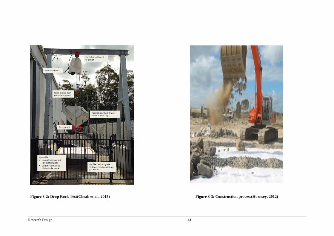
Research Design 41
Figure 3-2: Drop Rock Test(Cheah et al., 2015)
Figure 3-3: Construction process(Hornsey, 2012)
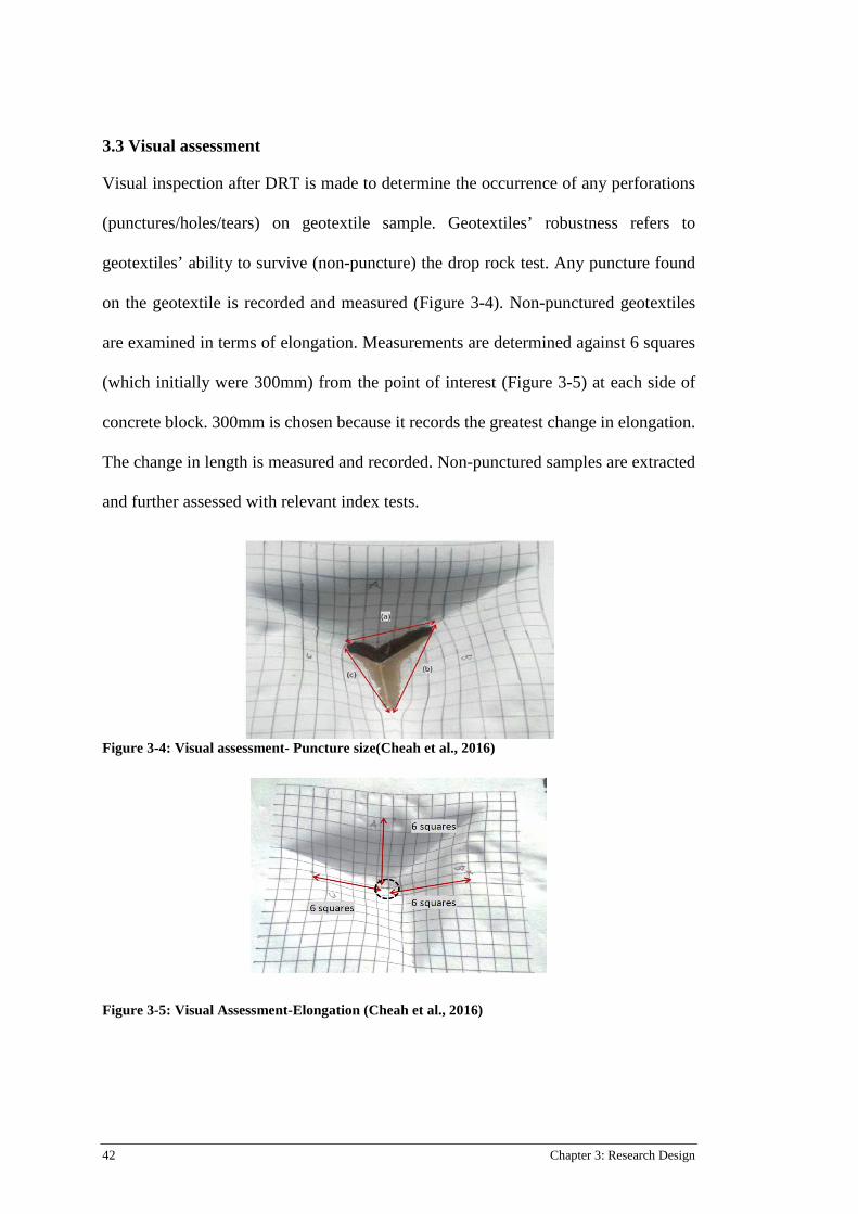
42 Chapter 3: Research Design
3.3 Visual assessment
Visual inspection after DRT is made to determine the occurrence of any perforations
(punctures/holes/tears) on geotextile sample. Geotextiles’ robustness refers to
geotextiles’ ability to survive (non-puncture) the drop rock test. Any puncture found
on the geotextile is recorded and measured (Figure 3-4). Non-punctured geotextiles
are examined in terms of elongation. Measurements are determined against 6 squares
(which initially were 300mm) from the point of interest (Figure 3-5) at each side of
concrete block. 300mm is chosen because it records the greatest change in elongation.
The change in length is measured and recorded. Non-punctured samples are extracted
and further assessed with relevant index tests.
Figure 3-4: Visual assessment- Puncture size(Cheah et al., 2016)
Figure 3-5: Visual Assessment-Elongation (Cheah et al., 2016)
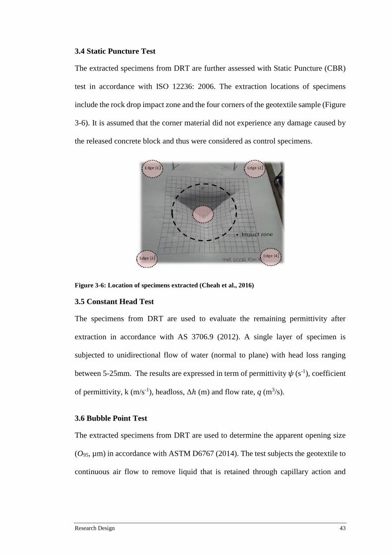
Research Design 43
3.4 Static Puncture Test
The extracted specimens from DRT are further assessed with Static Puncture (CBR)
test in accordance with ISO 12236: 2006. The extraction locations of specimens
include the rock drop impact zone and the four corners of the geotextile sample (Figure
3-6). It is assumed that the corner material did not experience any damage caused by
the released concrete block and thus were considered as control specimens.
Figure 3-6: Location of specimens extracted (Cheah et al., 2016)
3.5 Constant Head Test
The specimens from DRT are used to evaluate the remaining permittivity after
extraction in accordance with AS 3706.9 (2012). A single layer of specimen is
subjected to unidirectional flow of water (normal to plane) with head loss ranging
between 5-25mm. The results are expressed in term of permittivity 𝜓𝜓 (s-1), coefficient
of permittivity, k (m/s-1), headloss, Δℎ (m) and flow rate, q (m3/s).
3.6 Bubble Point Test
The extracted specimens from DRT are used to determine the apparent opening size
(O95, µm) in accordance with ASTM D6767 (2014). The test subjects the geotextile to
continuous air flow to remove liquid that is retained through capillary action and

44 Chapter 3: Research Design
surface tension from the geotextiles. O95 corresponds with the geotextile opening size
that 95% of the pores are smaller than that size.
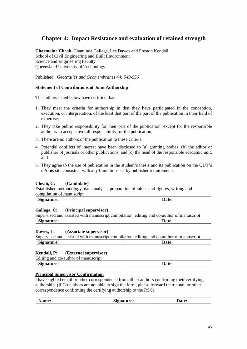
45
Chapter 4: Impact Resistance and evaluation of retained strength
Charmaine Cheah, Chaminda Gallage, Les Dawes and Preston Kendall School of Civil Engineering and Built Environment Science and Engineering Faculty Queensland University of Technology Published: Geotextiles and Geomembranes 44: 549-556
Statement of Contributions of Joint Authorship
The authors listed below have certified that: 1. They meet the criteria for authorship in that they have participated in the conception,
execution, or interpretation, of the least that part of the part of the publication in their field of expertise;
2. They take public responsibility for their part of the publication, except for the responsible author who accepts overall responsibility for the publication;
3. There are no authors of the publication to these criteria
4. Potential conflicts of interest have been disclosed to (a) granting bodies, (b) the editor or publisher of journals or other publications, and (c) the head of the responsible academic unit, and
5. They agree to the use of publication in the student’s thesis and its publication on the QUT’s ePrints site consistent with any limitations set by publisher requirements
Cheah, C: (Candidate) Established methodology, data analysis, preparation of tables and figures, writing and compilation of manuscript
Signature: Date: Gallage, C: (Principal supervisor) Supervised and assisted with manuscript compilation, editing and co-author of manuscript
Signature: Date: Dawes, L: (Associate supervisor) Supervised and assisted with manuscript compilation, editing and co-author of manuscript
Signature: Date: Kendall, P: (External supervisor) Editing and co-author of manuscript
Signature: Date: Principal Supervisor Confirmation I have sighted email or other correspondence from all co-authors confirming their certifying authorship. (If Co-authors are not able to sign the form, please forward their email or other correspondence confirming the certifying authorship to the RSC)
Name: Signature: Date:
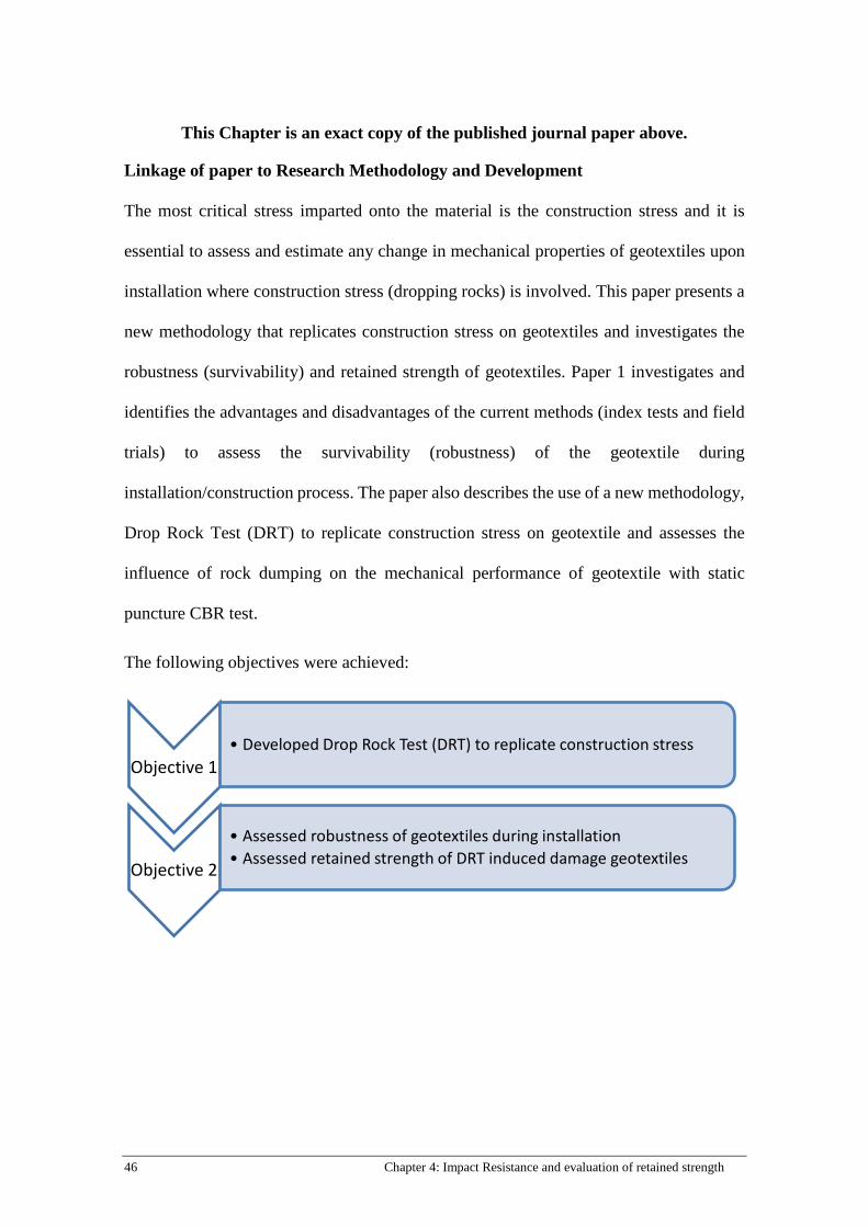
46 Chapter 4: Impact Resistance and evaluation of retained strength
This Chapter is an exact copy of the published journal paper above.
Linkage of paper to Research Methodology and Development
The most critical stress imparted onto the material is the construction stress and it is
essential to assess and estimate any change in mechanical properties of geotextiles upon
installation where construction stress (dropping rocks) is involved. This paper presents a
new methodology that replicates construction stress on geotextiles and investigates the
robustness (survivability) and retained strength of geotextiles. Paper 1 investigates and
identifies the advantages and disadvantages of the current methods (index tests and field
trials) to assess the survivability (robustness) of the geotextile during
installation/construction process. The paper also describes the use of a new methodology,
Drop Rock Test (DRT) to replicate construction stress on geotextile and assesses the
influence of rock dumping on the mechanical performance of geotextile with static
puncture CBR test.
The following objectives were achieved:
Objective 1• Developed Drop Rock Test (DRT) to replicate construction stress
Objective 2
• Assessed robustness of geotextiles during installation• Assessed retained strength of DRT induced damage geotextiles
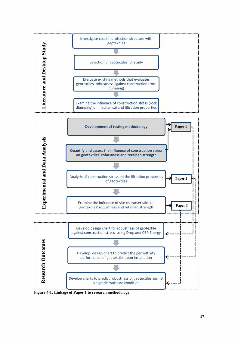
47
Figure 4-1: Linkage of Paper 1 to research methodology
Investigate coastal protection structure with geotextiles
Selection of geotextiles for study
Evaluate existing methods that evaluates geotextiles' robustness against construction (rock
dumping)
Examine the influence of construction stress (rock diumping) on mechanical and filtration properties
Development of testing methodology
Quantify and assess the influence of construction stress on geotextiles' robustness and retained strength
Analysis of construction stress on the filtration properties of geotextiles
Examine the influence of site characteristics on geotextiles' robustness and retained strength
Develop design chart for robustness of geotextile against construction stress using Drop and CBR Energy
Develop design chart to predict the permittivity performance of geotextile upon installation
Develop charts to predict robustness of geotextiles agsinst subgrade moisture condition
Lite
ratu
re a
nd D
eskt
op S
tudy
E
xper
imen
tal a
nd D
ata
Ana
lysi
s R
esea
rch
Out
com
es
Paper 1
Paper 2
Paper 3
48 Chapter 4: Impact Resistance and evaluation of retained strength
Abstract
Over the last few decades, geotextiles have progressively been incorporated into
geotechnical applications, especially in the field of coastal engineering. Geotextile
materials often act as separator and a filter layer between rocks laid above and subgrade
beneath. This versatile material has gradually substituted traditional granular materials
because of its ease of installation, consistent quality and labour cost-efficiency. However,
geotextiles often suffer damage during installation due to high dynamic bulk loading of
rock placement. This can degrade geotextiles’ mechanical strength. The properties
considered in this paper include the impact resistance and retained strength of geotextiles.
In general, the greater the impact energy applied to geotextiles, the greater the potential
for damage. Results highlight the inadequacy of using index derived values as indicators
that determine geotextiles performance on site because test results showed that geotextiles
(staple fibre (SF) and continuous filament (CF)) with better mechanical properties did not
outperform lower mechanical strength materials. The toughest CF product with a CBR
index value of 9696N shows inferior impact resistance compared to SF product with the
least CBR strength (2719N) given the same impact energy of 9.02kJ. Test results also
indicated that the reduction of strength for CF materials were much greater (between 20-
50%) compared to SF materials (between 0- 5%) when subjected to the same impact
energy of 4.52kJ.
KEYWORDS: Geosynthetics, Drop Rock Test, Impact Resistance, Unsaturated
Subgrade, Retained Strength
4.1 Introduction
For more than 40 years, the use of geotextiles in coastal engineering applications has been
increasing. The versatility (bi-dimensional and flexible), ease of installation, consistent
49
material properties (mechanical and hydraulic) and cost-effectiveness of geotextiles offer
great advantages as construction materials (Giroud, 1984; Palmeira et al., 2008). As such,
geotextiles have gradually replaced granular materials as separator and filter layer
beneath revetments armour, gabions and riprap (Christopher and Fischer, 1992).
Unfortunately, geotextiles are often damaged during installation/construction phase. Past
studies and on-site investigations (Chew et al., 1999; Heerten, 2008; Hornsey, 2012;
Wong et al., 2000b)led authors to agree the mechanical action during placement of armour
rocks can cause noticeable damage to geotextiles in one form or another. This justifies
the need to examine geotextiles’ damage during installation to estimate the short-term
performance of geotextiles. Identifying the retained strength of the material straight after
installation allows engineers to be able to isolate installation damage from hydraulic,
physical, chemical, and biological damage that accounts for the deterioration of installed
geotextiles. The expected serviceability of the material can be achieved with greater
confidence when engineers are provided with the retained strength of the initially installed
material.
The key factor ensuring geotextile to perform its function is the impact resistance
of the material to resist the perforation of the rocks during installation. Rosete et al. (2013)
point out that not only can installation damage on geotextile affect mechanical (tensile)
strength, but also the functionality of geotextiles such as separation and/or filtration can
be undermined. In 1992, Christopher and Fischer inferred that any design efforts for
structures with geotextile filters would be useless if the material is damaged during
installation process and further asserted that “Swiss cheese does not make a good filter”.
Similarly, Heerten (2008) asserts that any geotextile filtration design would be
meaningless if the material suffers puncturing during installation.
50 Chapter 4: Impact Resistance and evaluation of retained strength
Engineers and designers often rely on index values specification, design guidelines
and installation height limitations to minimise damage inflicted on geotextiles during
installation process. Specifying minimum index values as survivability requirement is
risky as index tests fail to simulate field conditions. Furthermore, the extensive drop
testing completed in Singapore revealed that geotextiles with better mechanical properties
such as tensile strength and CBR force do not necessarily have better performance(Chew
et al., 1999; Wong et al., 2000b). Wong et al. (2000b)found a negative correlation
between tensile strength and CBR force of geotextiles with the expected damage. Results
reveal that geotextile with superior mechanical strength did not outperform materials of
lower strength properties. Hence, index test values should not govern the impact
resistance of geotextiles.
Design guidelines and charts available are mostly based on physical parameters
such as mass and thickness of geotextiles. Mass of geotextile represents the amount of
polymer used in manufacturing of the geotextile product (Wong et al., 2000b). Though
the mass of geotextile is often associated with its mechanical performance this parameter
is merely a relative indicator. It is only relevant if the same manufactured form of fabric
is compared. Combined technological developments, reformed manufacturing techniques
and improved quality of raw materials could result in better performing geotextile given
the same amount of mass (Palmeira et al., 2008; Wong et al., 2000b). As such, mass does
not necessarily reflect the impact resistance of geotextile.
Engineers and designers would often carry out field trials to determine the
appropriate drop height in installation to minimise the risk of punctures inflicted on
geotextiles(Ameraunga et al., 2006; Holtz et al., 1997). Chew et al. (1999) and Wong et
al. (2000b) agreed that there is neither a standard methodology for field trials nor a
51
standard damage evaluation approach adopted by the industry. This led Chew et al. (1999)
to propose a standardized drop test (SDT) to measure the puncture resistance of
geotextiles in a quantifiable and empirical manner. However, despite the reproducible
results obtained from SDT, it has been shown that geotextile puncture is a random event
and a repeated number of tests may be necessary to capture the risk of puncturing the
geotextile. Though, SDT may closely simulate field conditions, the variation of
overlaying armour rocks in size and shapes and subgrade conditions makes it harder to
determine the safe puncture threshold. Hence, there is a need to design a test apparatus
to isolate and control the parameters so that governing factors of damage are identified.
In 1978, BAW developed a standard impact test to simulate the dynamic impact of
a falling armour rock on geosynthetics (current issue: RPG (1994)) Heibaum (2014)
describes the dynamic impact is simulated by releasing a drop hammer with a tip edge
onto the geotextile sample laid above a soil sample at determined drop energy. The BAW
guideline highlights the use of drop energy as a function of rock size and drop height, a
functional versatile approach to simulate dynamic impact. However, damage simulated
from this approach does not fully replicate the damage sustained by geotextiles during
installation. The cylindrical drop hammer with a tip edge remains in dispute: the question
of the armour rock represented with a cylindrical drop hammer still invites contention.
When designing geotextiles for coastal applications the effect of possible damage
should be taken account, including mechanical damage during installation. Hence long
term observational studies have taken place to determine the extent of damage after a
certain number years in service, this typically ranges from 5-14 years (Christopher, 1983;
Lawson, 1982; Loke et al., 1995; Mannsbart and Christopher, 1997; Wong et al., 2000b).
Studies suggest that there is a substantial deterioration in geotextiles’ mechanical strength
52 Chapter 4: Impact Resistance and evaluation of retained strength
from samples that were exhumed from project sites. Results gathered from these studies
provide engineers the relevant information to develop safety factors and design
guidelines. However, it is difficult to determine the durability of geotextile during
installation as various damage factors are correlated when it is examined after a number
of years. These damages could include tension loading (during installation and/or
operational phase), heavy wave attacks on armour rocks and/or creep under permanent
loading. It will be useful if engineers are able to identify the initial material strength
reduction upon installation, as design engineers could account for the mechanical
deterioration of the material during operational stage.
This study utilizes a new approach, Drop Rock Test (DRT) (Cheah et al., 2015;
Kendall et al., 2014b) to simulate damage on a geotextile during installation. The impact
resistance of the material is examined by recording the number of samples that survived
(no punctures) for a series of drop rock tests. Surviving samples are directly exhumed and
tested for changes in mechanical strength using CBR puncture tests. Results of
experimental investigations on impact resistance and retained CBR strength are presented
in this paper.
4.2 Materials and Experimental Description
4.2.1 Drop Rock Test
Figure 1 illustrates the DRT apparatus which consists of a gantry crane with a lifting
capacity of 1550kg, concrete block and a subgrade containment unit. As shown in Figure
1, two A-frames of rectangular hollow sections are bolted to concrete blocks to provide
support to the girder section. The concrete block was constructed with a 90o tip facing
downwards to represent the worst possible damage inflicted onto geotextile by an armour
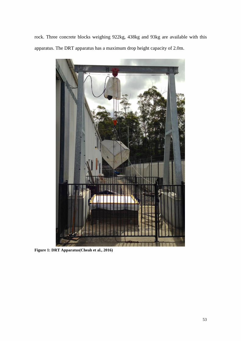
53
rock. Three concrete blocks weighing 922kg, 438kg and 93kg are available with this
apparatus. The DRT apparatus has a maximum drop height capacity of 2.0m.
Figure 1: DRT Apparatus(Cheah et al., 2016)
54 Chapter 4: Impact Resistance and evaluation of retained strength
The DRT procedure adopted in this study is summarised as follows:
i. A concrete block of 922kg with a 90o tip was used in DRT to deliver constant
impact energy onto geotextile for a specified drop height. This orientation ensures
the greatest mechanical stress inflicted on geotextile.
ii. Each geotextile sample measured 1.8m by 2.0m and was stencilled with a grid of
50mm by 50mm, where the concrete block is targeted to fall. Any physical
changes can be observed by measuring the change in the length stencilled on the
geotextile.
iii. The subgrade confined box was filled with sand compacted using a hand tamping
system. A 4.2kg tamper of 200mm x 300mm x 700mm (L x W x H) was released
from a height of 0.5m and repeated 30 times (6x5 grid pattern)., The centre region
of the subgrade was repeatedly emptied and refilled due to the falling of concrete
block; this area was tamped again by a 3 by 5 grid pattern to ensure consistent
compaction.
iv. The concrete block was electrically winched up to the desired drop height and was
laterally moved across with a trolley along the crane rail. The drop height was
measured from the bottom tip of the test block to the surface of the geotextile with
a T-gauge. The testing block was then disengaged from the quick release
mechanism once in position.
v. After the drop, the concrete block and G-clamps were removed, any punctures
found on the geotextile sample were considered a failure and the size of damage
was measured (Figure 2a). For survived (non-punctured) samples, elongation
values were measured against 6 grid squares (which initially 300mm, as each
square is 50mm by 50mm) from the point of intersection (Figure 2b).
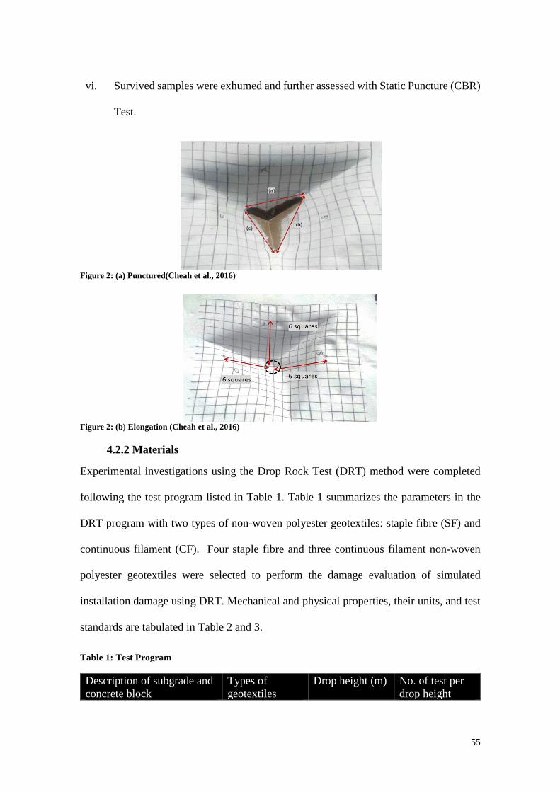
55
vi. Survived samples were exhumed and further assessed with Static Puncture (CBR)
Test.
Figure 2: (a) Punctured(Cheah et al., 2016)
Figure 2: (b) Elongation (Cheah et al., 2016)
4.2.2 Materials
Experimental investigations using the Drop Rock Test (DRT) method were completed
following the test program listed in Table 1. Table 1 summarizes the parameters in the
DRT program with two types of non-woven polyester geotextiles: staple fibre (SF) and
continuous filament (CF). Four staple fibre and three continuous filament non-woven
polyester geotextiles were selected to perform the damage evaluation of simulated
installation damage using DRT. Mechanical and physical properties, their units, and test
standards are tabulated in Table 2 and 3.
Table 1: Test Program
Description of subgrade and concrete block
Types of geotextiles
Drop height (m) No. of test per drop height
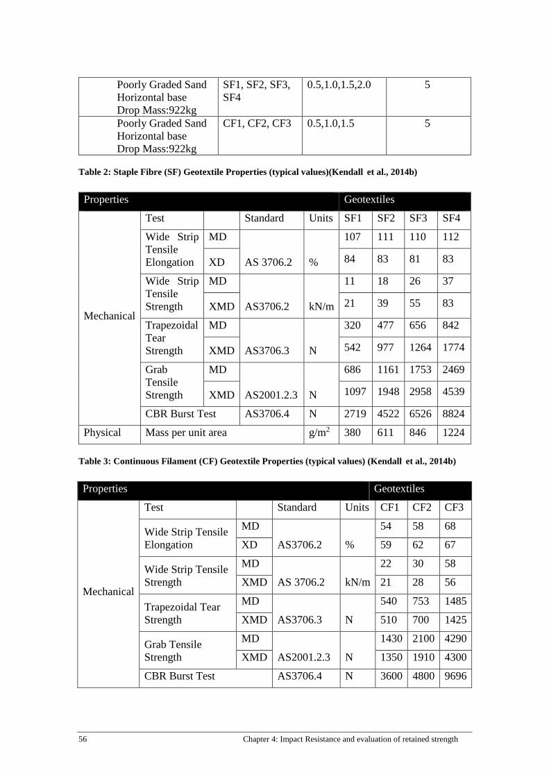
56 Chapter 4: Impact Resistance and evaluation of retained strength
Poorly Graded Sand Horizontal base Drop Mass:922kg
SF1, SF2, SF3, SF4
0.5,1.0,1.5,2.0 5
Poorly Graded Sand Horizontal base Drop Mass:922kg
CF1, CF2, CF3 0.5,1.0,1.5 5
Table 2: Staple Fibre (SF) Geotextile Properties (typical values)(Kendall et al., 2014b)
Table 3: Continuous Filament (CF) Geotextile Properties (typical values) (Kendall et al., 2014b)
Properties Geotextiles
Mechanical
Test Standard Units SF1 SF2 SF3 SF4
Wide Strip Tensile Elongation
MD
AS 3706.2 %
107 111 110 112
XD 84 83 81 83
Wide Strip Tensile Strength
MD
AS3706.2 kN/m
11 18 26 37
XMD 21 39 55 83
Trapezoidal Tear Strength
MD
AS3706.3 N
320 477 656 842
XMD 542 977 1264 1774
Grab Tensile Strength
MD
AS2001.2.3 N
686 1161 1753 2469
XMD 1097 1948 2958 4539
CBR Burst Test AS3706.4 N 2719 4522 6526 8824
Physical Mass per unit area g/m2 380 611 846 1224
Properties Geotextiles
Mechanical
Test Standard Units CF1 CF2 CF3
Wide Strip Tensile Elongation
MD
AS3706.2 %
54 58 68
XD 59 62 67
Wide Strip Tensile Strength
MD
AS 3706.2 kN/m
22 30 58
XMD 21 28 56
Trapezoidal Tear Strength
MD
AS3706.3 N
540 753 1485
XMD 510 700 1425
Grab Tensile Strength
MD
AS2001.2.3 N
1430 2100 4290
XMD 1350 1910 4300
CBR Burst Test AS3706.4 N 3600 4800 9696
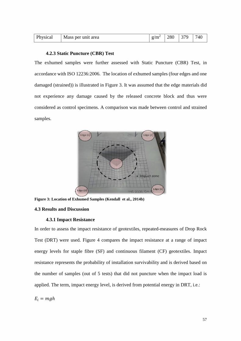
57
4.2.3 Static Puncture (CBR) Test
The exhumed samples were further assessed with Static Puncture (CBR) Test, in
accordance with ISO 12236:2006. The location of exhumed samples (four edges and one
damaged (strained)) is illustrated in Figure 3. It was assumed that the edge materials did
not experience any damage caused by the released concrete block and thus were
considered as control specimens. A comparison was made between control and strained
samples.
Figure 3: Location of Exhumed Samples (Kendall et al., 2014b)
4.3 Results and Discussion
4.3.1 Impact Resistance
In order to assess the impact resistance of geotextiles, repeated-measures of Drop Rock
Test (DRT) were used. Figure 4 compares the impact resistance at a range of impact
energy levels for staple fibre (SF) and continuous filament (CF) geotextiles. Impact
resistance represents the probability of installation survivability and is derived based on
the number of samples (out of 5 tests) that did not puncture when the impact load is
applied. The term, impact energy level, is derived from potential energy in DRT, i.e.:
𝐸𝐸𝑖𝑖 = 𝑚𝑚𝑚𝑚ℎ
Physical Mass per unit area g/m2 280 379 740
58 Chapter 4: Impact Resistance and evaluation of retained strength
Where m is the mass of rock, g is the gravitational acceleration and h represents the
installation height. (Kendall et al. (2014a)) point out that impact energy can conveniently
summarize the relevant installation specifications such as rock size and drop height. Thus,
impact energy is chosen to represent the results. In general, the potential for damage
increases with higher impact energy.
It is accepted that with greater drop heights, the greater the impact energy applied
on the laid geotextile, hence, the mechanical stress induced on geotextile is greater as
well. Therefore, it is assumed that the material with greater mechanical properties would
have greater impact resistance. However, Figure 4 depicts that the above concept should
simply be applied for materials for the same manufactured form of fabric. Tables 2 and 3
show that mechanical properties of CF samples are generally greater (indicating better
impact performance) than SF samples however DRT tests showed the opposite trend.
Results showed that CF3 with 9696 N of CBR Burst Strength did not outperform the SF1
geotextile with 2719N in DRT tests. As shown in Figure 4, SF geotextiles have greater
impact resistance compared to CF geotextiles. This highlights the risk on relying on index
test values which is inadequate in reflecting geotextile performance on site. This result
could likely to be related to the fibre characteristics of CF, which are longer in its fibre
length compared to SF geotextiles.
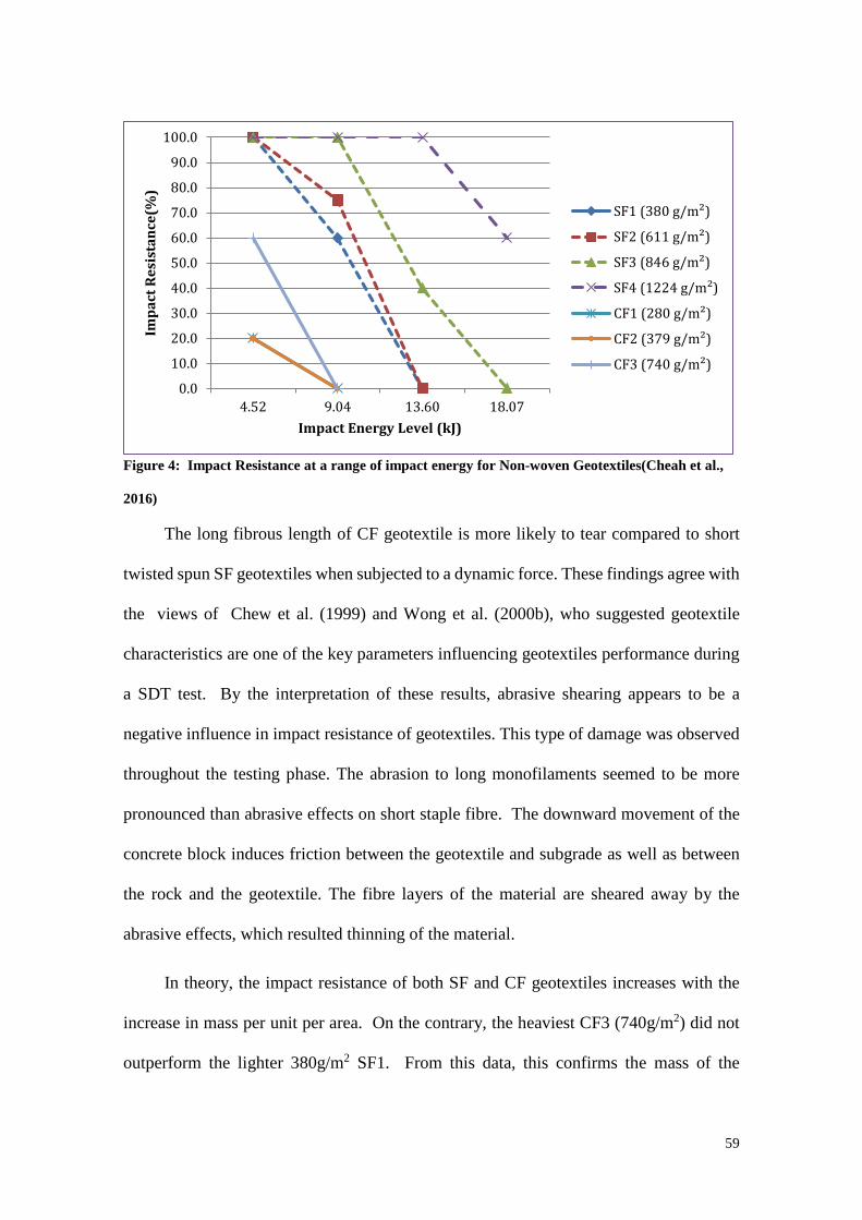
59
Figure 4: Impact Resistance at a range of impact energy for Non-woven Geotextiles(Cheah et al.,
2016)
The long fibrous length of CF geotextile is more likely to tear compared to short
twisted spun SF geotextiles when subjected to a dynamic force. These findings agree with
the views of Chew et al. (1999) and Wong et al. (2000b), who suggested geotextile
characteristics are one of the key parameters influencing geotextiles performance during
a SDT test. By the interpretation of these results, abrasive shearing appears to be a
negative influence in impact resistance of geotextiles. This type of damage was observed
throughout the testing phase. The abrasion to long monofilaments seemed to be more
pronounced than abrasive effects on short staple fibre. The downward movement of the
concrete block induces friction between the geotextile and subgrade as well as between
the rock and the geotextile. The fibre layers of the material are sheared away by the
abrasive effects, which resulted thinning of the material.
In theory, the impact resistance of both SF and CF geotextiles increases with the
increase in mass per unit per area. On the contrary, the heaviest CF3 (740g/m2) did not
outperform the lighter 380g/m2 SF1. From this data, this confirms the mass of the
0.0
10.0
20.0
30.0
40.0
50.0
60.0
70.0
80.0
90.0
100.0
4.52 9.04 13.60 18.07
Impa
ct R
esis
tanc
e(%
)
Impact Energy Level (kJ)
SF1 (380 g/m²)
SF2 (611 g/m²)
SF3 (846 g/m²)
SF4 (1224 g/m²)
CF1 (280 g/m²)
CF2 (379 g/m²)
CF3 (740 g/m²)
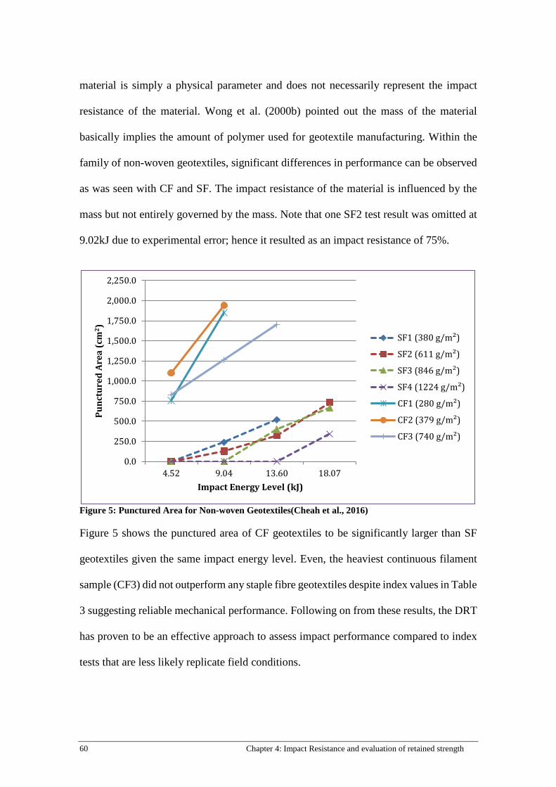
60 Chapter 4: Impact Resistance and evaluation of retained strength
material is simply a physical parameter and does not necessarily represent the impact
resistance of the material. Wong et al. (2000b) pointed out the mass of the material
basically implies the amount of polymer used for geotextile manufacturing. Within the
family of non-woven geotextiles, significant differences in performance can be observed
as was seen with CF and SF. The impact resistance of the material is influenced by the
mass but not entirely governed by the mass. Note that one SF2 test result was omitted at
9.02kJ due to experimental error; hence it resulted as an impact resistance of 75%.
Figure 5: Punctured Area for Non-woven Geotextiles(Cheah et al., 2016)
Figure 5 shows the punctured area of CF geotextiles to be significantly larger than SF
geotextiles given the same impact energy level. Even, the heaviest continuous filament
sample (CF3) did not outperform any staple fibre geotextiles despite index values in Table
3 suggesting reliable mechanical performance. Following on from these results, the DRT
has proven to be an effective approach to assess impact performance compared to index
tests that are less likely replicate field conditions.
0.0
250.0
500.0
750.0
1,000.0
1,250.0
1,500.0
1,750.0
2,000.0
2,250.0
4.52 9.04 13.60 18.07
Punc
ture
d Ar
ea (c
m2 )
Impact Energy Level (kJ)
SF1 (380 g/m²)
SF2 (611 g/m²)
SF3 (846 g/m²)
SF4 (1224 g/m²)
CF1 (280 g/m²)
CF2 (379 g/m²)
CF3 (740 g/m²)
61
Lawson (1992) correlates the geotextiles filtration performance with the number of
punctures and the size of puncture and as expected with greater damage, the filtration
efficiency of the material reduces. Lawson suggests there should not be too many
punctures or large punctures inflicted onto the material for the geotextile to function
reasonably. This study is unable to determine the number of punctures on geotextile as
each laid geotextile only experienced one rock drop per installation height instead of the
bulk loading of armour rocks. If the geotextiles punctured, it was a single puncture. Figure
5 shows the size of punctured area of geotextiles. The punctured areas of geotextiles are
shaped in-line with crater of the concrete block. Generally, the size of damaged area is
larger with higher impact energy. The size of punctured area represents the damaged size
inflicted on geotextiles, but since the concrete block is constructed with a 90o sharp edged
to simulate the most critical form of installation damage, it signifies the maximum
possible damaged area.
Over the past few decades, the manufacturing quality, installation practice and
performance expectations of geotextiles have steadily increased. For many years,
installed geotextiles with punctures were deemed stable as long the structure remains
static, but with continuous cyclic wave actions, armour rocks are unable to constantly
remain static under hydraulic action. Hence, the punctured area will not be sealed.
Increased expectations for life time serviceability and filter integrity recognize that a shift
in the armour rock can expose the damaged area and put stability of the structure at risk.
As acknowledged by authors (Christopher and Fischer, 1992; Heerten, 2007, 2008),
filtration designs will be compromised if the geotextile material punctures. Hence,
throughout the testing program, any visible puncture noted was considered a failure.
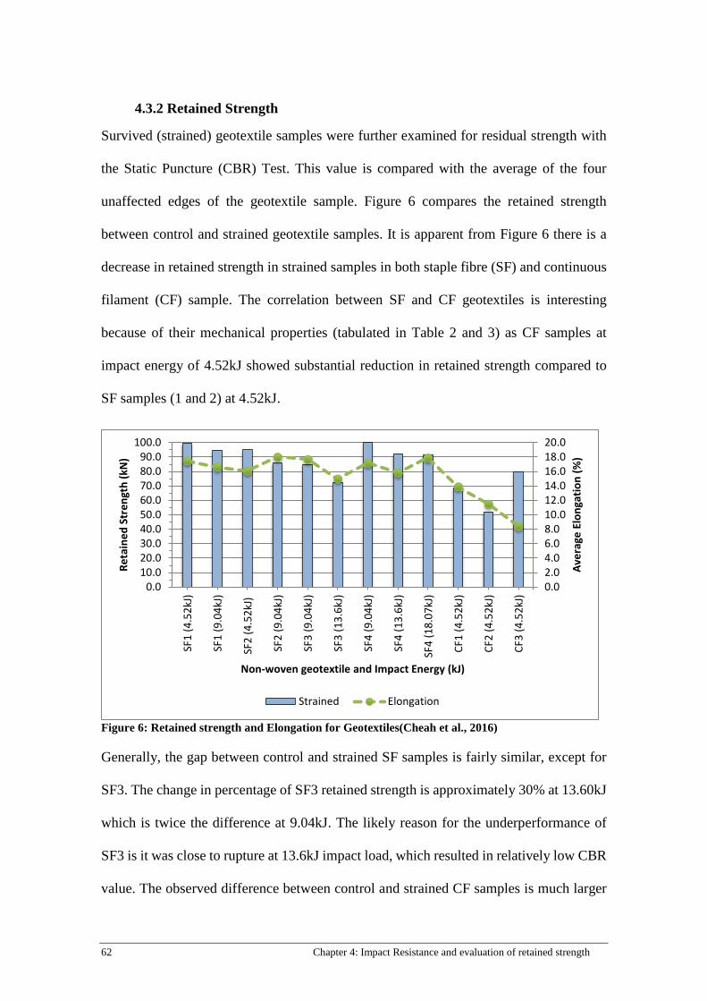
62 Chapter 4: Impact Resistance and evaluation of retained strength
4.3.2 Retained Strength
Survived (strained) geotextile samples were further examined for residual strength with
the Static Puncture (CBR) Test. This value is compared with the average of the four
unaffected edges of the geotextile sample. Figure 6 compares the retained strength
between control and strained geotextile samples. It is apparent from Figure 6 there is a
decrease in retained strength in strained samples in both staple fibre (SF) and continuous
filament (CF) sample. The correlation between SF and CF geotextiles is interesting
because of their mechanical properties (tabulated in Table 2 and 3) as CF samples at
impact energy of 4.52kJ showed substantial reduction in retained strength compared to
SF samples (1 and 2) at 4.52kJ.
Figure 6: Retained strength and Elongation for Geotextiles(Cheah et al., 2016)
Generally, the gap between control and strained SF samples is fairly similar, except for
SF3. The change in percentage of SF3 retained strength is approximately 30% at 13.60kJ
which is twice the difference at 9.04kJ. The likely reason for the underperformance of
SF3 is it was close to rupture at 13.6kJ impact load, which resulted in relatively low CBR
value. The observed difference between control and strained CF samples is much larger
0.02.04.06.08.010.012.014.016.018.020.0
0.010.020.030.040.050.060.070.080.090.0
100.0
SF1
(4.5
2kJ)
SF1
(9.0
4kJ)
SF2
(4.5
2kJ)
SF2
(9.0
4kJ)
SF3
(9.0
4kJ)
SF3
(13.
6kJ)
SF4
(9.0
4kJ)
SF4
(13.
6kJ)
SF4
(18.
07kJ
)
CF1
(4.5
2kJ)
CF2
(4.5
2kJ)
CF3
(4.5
2kJ)
Aver
age
Elon
gatio
n (%
)
Reta
ined
Str
engt
h (k
N)
Non-woven geotextile and Impact Energy (kJ)
Strained Elongation
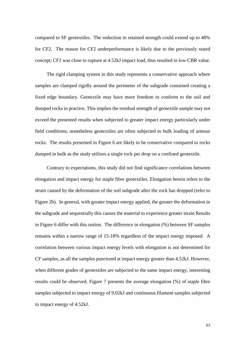
63
compared to SF geotextiles. The reduction in retained strength could extend up to 48%
for CF2. The reason for CF2 underperformance is likely due to the previously stated
concept; CF2 was close to rupture at 4.52kJ impact load, thus resulted in low CBR value.
The rigid clamping system in this study represents a conservative approach where
samples are clamped rigidly around the perimeter of the subgrade contained creating a
fixed edge boundary. Geotextile may have more freedom to conform to the soil and
dumped rocks in practice. This implies the residual strength of geotextile sample may not
exceed the presented results when subjected to greater impact energy particularly under
field conditions; nonetheless geotextiles are often subjected to bulk loading of armour
rocks. The results presented in Figure 6 are likely to be conservative compared to rocks
dumped in bulk as the study utilizes a single rock per drop on a confined geotextile.
Contrary to expectations, this study did not find significance correlations between
elongation and impact energy for staple fibre geotextiles. Elongation herein refers to the
strain caused by the deformation of the soil subgrade after the rock has dropped (refer to
Figure 2b). In general, with greater impact energy applied, the greater the deformation in
the subgrade and sequentially this causes the material to experience greater strain Results
in Figure 6 differ with this notion. The difference in elongation (%) between SF samples
remains within a narrow range of 15-18% regardless of the impact energy imposed. A
correlation between various impact energy levels with elongation is not determined for
CF samples, as all the samples punctured at impact energy greater than 4.52kJ. However,
when different grades of geotextiles are subjected to the same impact energy, interesting
results could be observed. Figure 7 presents the average elongation (%) of staple fibre
samples subjected to impact energy of 9.02kJ and continuous filament samples subjected
to impact energy of 4.52kJ.
64 Chapter 4: Impact Resistance and evaluation of retained strength
Figure 7:Av. Elongation (%) of Non-woven Geotextiles subjected to different Impact Energy (kJ)* Note*: Figure 7 did not include elongations of SF products at 4.52kJ because samples with the same properties are no longer available. (Cheah et al., 2016)
Figure 7 shows that SF samples had similar elongation among all product grades
subjected to same amount of impact energy. The higher grade materials (SF3 and SF4)
have significantly superior strength properties but they did not show a significant
difference in ability to elongate compared to the lower grade geotextile, SF1. These
results are likely related to the consistent amount of subgrade deformation occurring
during each impact test. This highlights the inadequacy of index properties being
measured as performance indicators. The mechanical properties obtained from the
various index tests (Table 2 and 3) measure the elongation in both cross-machine and
machine dimension but do not model the deformation experienced by geotextiles caused
by the armour rocks. These index tests do not account for the soil-geotextile interaction.
The sublayer/subsoil beneath the geotextile contributes to the ability of geotextiles to
withstand strain during installation and dumping force caused by the armour rock. It is
important to take account of the soil-geotextile interaction as the stability of geotextile
layer strongly depends on the type and composition of sublayer/subsoil. In contrast, the
elongation behaviour CF geotextile samples upon impact showed a trend with increasing
geotextile grade; the higher grade the material, the lower the expected strain. The
0.02.04.06.08.0
10.012.014.016.018.020.0
SF1
SF2
SF3
SF4
CF1
CF2
CF3
Aver
age
Elon
gati
on (%
)
Non-woven Geotextile
4.52kJ
9.02kJ
65
observed trend could be attributed to the influence of CF’s tensile strength on the amount
of subgrade deformation. Interestingly, though both SF and CF samples are categorised
as non-woven geotextiles with similar mechanical strength, they responded distinctly.
4.4 Conclusion
The long term durability and serviceability of geotextiles in structures depends
significantly on the impact resistance of geotextile during the harsh installation
conditions. Any functions such as separator and filter layer could be compromised when
the material suffers severe damage. The study utilises a new approach, Drop Rock Test
(DRT) to assess the impact resistance and retained strength of geotextiles. The DRT is a
reliable scientific method to simulate controlled installation conditions which is able to
generate consistent and reproducible results.
The experimental investigations in this study illustrate the use of Drop Rock Test
(DRT) to assess the impact resistance and retained strength of geotextiles. The impact
resistance reflects survivability during installation, and the damaged size area can be used
to indicate the worst possible damage that may be inflicted on the geotextiles. Findings
suggest the potential of damage to the material increases with higher impact energy, as
the greater the impact energy, the greater the mechanical stress is induced onto the laid
geotextile. Results are in agreement with Wong et al. (2000b) findings which showed
index derived values are very limited in their ability to quantify the impact resistance of
the material. Results reveal that the lighter staple fibre non-woven geotextile (380g/m2)
outperforms the heavier continuous filament non-woven geotextile (740g/m2) which
implies the use of mass per unit area as a relative indicator for installation robustness
should be discouraged. Hence, neither index derived values nor the mass should solely
govern the impact resistance of geotextiles.
66 Chapter 4: Impact Resistance and evaluation of retained strength
Retained strength of the survived sample represents the retained strength of the
installed geotextile on site. The results are in accord with the long term observational
studies (Christopher, 1983; Lawson, 1982; Loke et al., 1995; Mannsbart and Christopher,
1997) indicating noticeable loss in mechanical strength. However, results from the long
term observation studies are only obtained after a number of installation years which
makes it harder for engineers and designers to accurately isolate factors that accounts
from the mechanical deterioration of installed geotextiles (installation damage/cyclic
waves/weathering). Findings showed that the reduction in retained strength for SF
geotextiles and CF geotextiles could extend up to approximately 30% and 50%
respectively.
Acknowledgements
This study was carried out as part of the first author’s PhD research at Queensland
University of Technology (QUT) in Brisbane and therefore authors would like to
acknowledge QUT Australian Postgraduate Awards (APA) for providing scholarship to
the first author for her PhD study. Authors express their appreciation to Geofabrics Centre
of Excellence in Gold Coast Australia for providing financial support, test materials and
testing facilities for this study. Finally, the support given by QUT technical staff, QUT
undergraduate students and technical staff of Geofabrics Centre of Excellence Centre is
gratefully acknowledged.
References
AS 2001.2.3.2- 2001 Methods of test for textiles-Physical tests- Determination of maximum force using the grab method (ISO 13934-2:1999, MOD).
AS 3706.2-2012 Geotextiles-Methods of Test-Determination of tensile properties- Wide strip and grab method.
AS 3706.3-2012 Geotextiles- Methods of Test- Determination of tearing strength- Trapezoidal method.

67
AS 3706.4-2012 Geotextiles- Methods of test- Determination of burst strength- California Bearing ratio (CBR) Plunger method.
Ameraunga, J., Boyle, P.J., Loke, K.H., Hornsey, W., Stevens, M., 2006. Use of geotextiles to overcome challenging conditions at the seawall project in Port of Brisbane, 8th International Conference on Geosynthetics, Yokohama, Japan.
Cheah, C., Gallage, C., Dawes, L., Kendall, P., 2015. Effect of Simulated Rock Dumping on Geotextile, 12th Australia New Zealand Conference on Geomechanics, Wellington, New Zealand.
Chew, S.H., Karunaratne, G.P., Tan, S.A., Wong, W.K., 1999. Standardized Drop Test (SDT) to evaluate puncture resistance of geotextiles in coastal revetments, Rencontres Geosynthetics 99, Bordeaux, France, pp. 303-310.
Christopher, B.R., 1983. Evaluation of two geotextile installation in excess of a decade old. Transportation Research Record, 79-88.
Christopher, B.R., Fischer, G.R., 1992. Geotextile filtration principles, practices and problems. Geotextiles and Geomembranes 11, 337-353.
Giroud, J.P., 1984. Geotextiles and geomembranes. Geotextiles and Geomembranes 1, 5-40.
Heerten, G., 2007. Revetment Design- Lessons learnt from failures, 10th Australia New Zealand Conference on Geomechanics. Australian Geomechanics Society, Brisbane, pp. 324-329.
Heerten, G., 2008. Needle-punched nonwoven GTX in coastal engineering applications, Chinese-German Joint Symposium on Hydraulic and Ocean Engineering, Darmstadt, Germany.
Heibaum, M., 2014. Geosynthetics for waterways and flood protection structures – Controlling the interaction of water and soil. Geotextiles and Geomembranes 42, 374-393.
Holtz, R.D., Christopher, B.R., Berg, R.R., 1997. Geosythetic Engineering. BiTech Publishers Ltd., Richmond, British Columbia, Canada.
Hornsey, W.P., 2012. Geotextiles in specialise marine applications: an australia prespective over 32 years. Geofabrics Australasia.
Kendall, P., Austin, R.A., Cheah, C., 2014a. Installation Durability Testing of Revetment Geotextiles, 7th International Congress on Enviromental Geotechnics, Melbourne, Australia.
Kendall , P., Austin, R.A., Cheah , C., Lacey , M., 2014b. Large Scale Controlled Testing of Geotextile Puncture Resistance for Rock Impact, 10th International Conference on Geosynthetics. Deutsche Gesellschaft für Geotechnik e.V., Berlin Germany.
Lawson, C.R., 1982. Geotextile requirements for erosion control structures, Recent Developments in Ground Improvement Techniques, Proceedings of the International Sumposium. A. A. Balkema, Bangkok, Thail, pp. 177-192.
Lawson, C.R., 1992. Geotextile revetment filters. Geotextiles and Geomembranes 11, 431-448.
Loke, K.H., Lee, C.H., Lim, C.H., Chin, P.W., 1995. Performance of nonwoven geotextile in coastal protection works with marine clays: a case study. Nonwovens Industry 26, 60-64.
Mannsbart, G., Christopher, B.R., 1997. Long-term performance of nonwoven geotextile filters in five coastal and bank protection projects. Geotextiles and Geomembranes 15, 207-221.

68 Chapter 4: Impact Resistance and evaluation of retained strength
Palmeira, E.M., Tatsuoka, F., Bathurst, R.J., Stevenson, P.E., Zornberg, J.G., 2008. Advances in geosynthetics materials and applications for soil reinforcement and environmental protection works. Electronic Journal of Geotechnical Engineering. Bouquet 8, 1-38.
Rosete, A., Lopes, P.M., Pinho-Lopes, M., Lopes, M.L., 2013. Tensile and hydraulic properties of geosynthetics after mechanical damage and abrasion laboratory tests. Geosynthetics International 20, 358-374.
RPG, 1994. Guidelines for Testing Geotextiles for Navigable Waterways. Bundesanstalt für Wasserbau, Karlsruhe.
Wong, W., Chew, S., Karunaratne, G., Tan, S., Yee, K., 2000. Evaluating the Puncture Survivability of Geotextiles in Construction of Coastal Revetments, Advances in Transportation and Geoenvironmental Systems Using Geosynthetics, pp. 186-200.

69
Chapter 5: Measuring hydraulic properties of geotextiles after
installation
Charmaine Cheah, Chaminda Gallage, Les Dawes and Preston Kendall School of Civil Engineering and Built Environment Science and Engineering Faculty Queensland University of Technology Article submitted to: Geotextiles and Geomembranes (under review)
Statement of Contributions of Joint Authorship
The authors listed below have certified that: 1. They meet the criteria for authorship in that they have participated in the conception,
execution, or interpretation, of the least that part of the part of the publication in their field of expertise;
2. They take public responsibility for their part of the publication, except for the responsible author who accepts overall responsibility for the publication;
3. There are no authors of the publication to these criteria
4. Potential conflicts of interest have been disclosed to (a) granting bodies, (b) the editor or publisher of journals or other publications, and (c) the head of the responsible academic unit, and
5. They agree to the use of publication in the student’s thesis and its publication on the QUT’s ePrints site consistent with any limitations set by publisher requirements
Cheah, C: (Candidate) Established methodology, data analysis, preparation of tables and figures, writing and compilation of manuscript
Signature: Date: Gallage, C: (Principal supervisor) Supervised and assisted with manuscript compilation, editing and co-author of manuscript
Signature: Date: Dawes, L: (Associate supervisor) Supervised and assisted with manuscript compilation, editing and co-author of manuscript
Signature: Date: Kendall, P: (External supervisor) Editing and co-author of manuscript
Signature: Date: Principal Supervisor Confirmation I have sighted email or other correspondence from all co-authors confirming their certifying authorship. (If Co-authors are not able to sign the form, please forward their email or other correspondence confirming the certifying authorship to the RSC)
Name: Signature: Date:
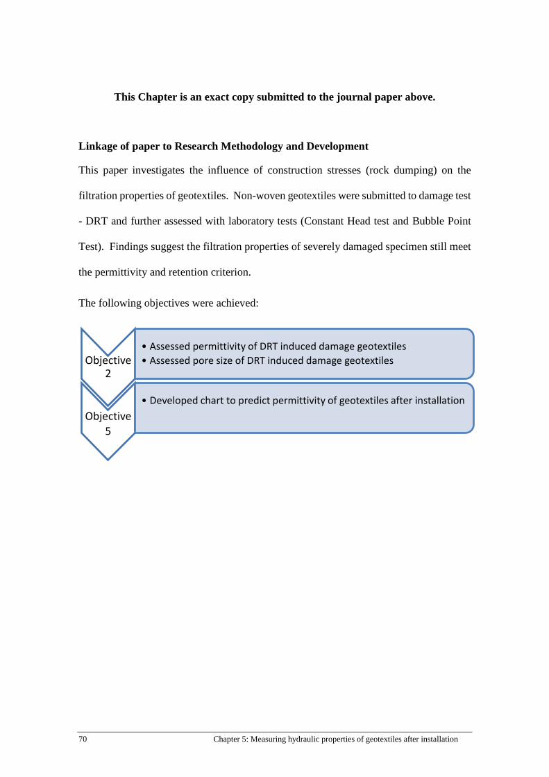
70 Chapter 5: Measuring hydraulic properties of geotextiles after installation
This Chapter is an exact copy submitted to the journal paper above.
Linkage of paper to Research Methodology and Development
This paper investigates the influence of construction stresses (rock dumping) on the
filtration properties of geotextiles. Non-woven geotextiles were submitted to damage test
- DRT and further assessed with laboratory tests (Constant Head test and Bubble Point
Test). Findings suggest the filtration properties of severely damaged specimen still meet
the permittivity and retention criterion.
The following objectives were achieved:
Objective 2
• Assessed permittivity of DRT induced damage geotextiles• Assessed pore size of DRT induced damage geotextiles
Objective5
• Developed chart to predict permittivity of geotextiles after installation
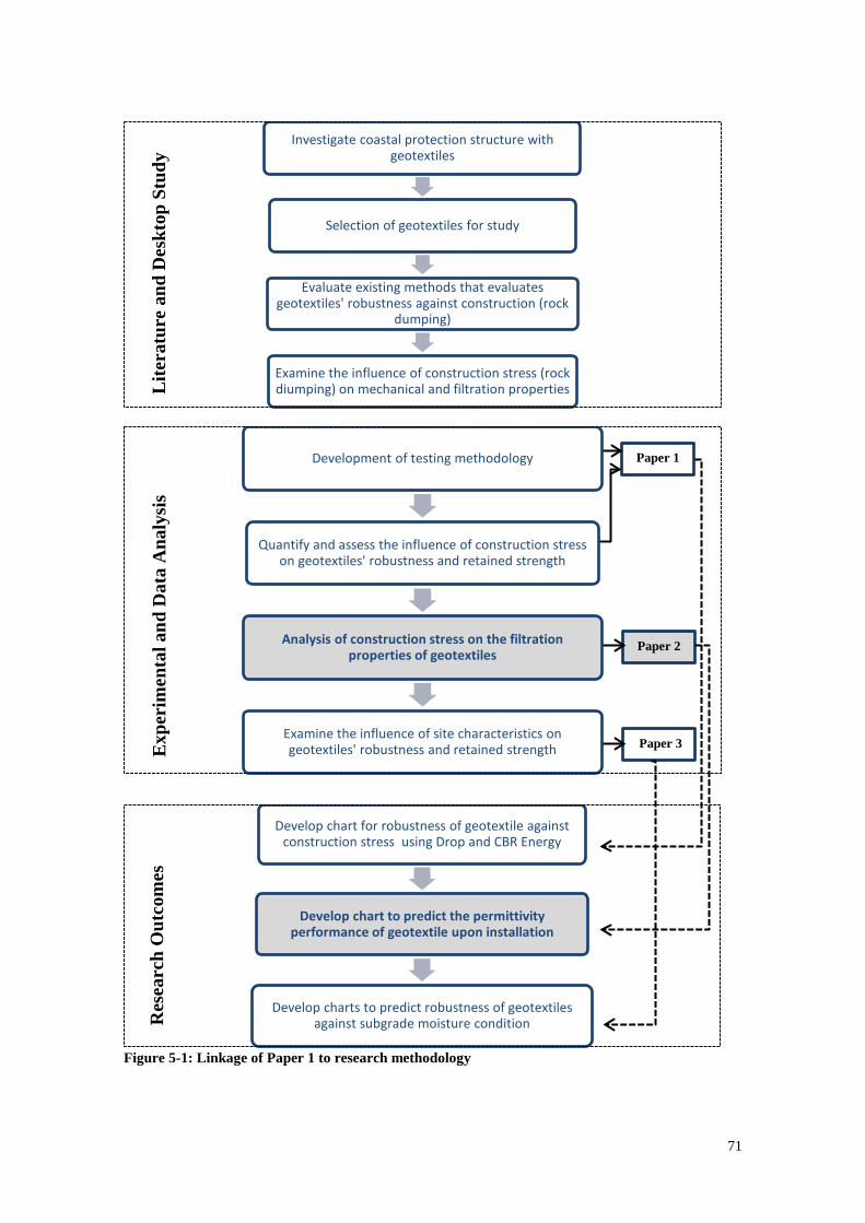
71
Figure 5-1: Linkage of Paper 1 to research methodology
Investigate coastal protection structure with geotextiles
Selection of geotextiles for study
Evaluate existing methods that evaluates geotextiles' robustness against construction (rock
dumping)
Examine the influence of construction stress (rock diumping) on mechanical and filtration properties
Development of testing methodology
Quantify and assess the influence of construction stress on geotextiles' robustness and retained strength
Analysis of construction stress on the filtration properties of geotextiles
Examine the influence of site characteristics on geotextiles' robustness and retained strength
Develop chart for robustness of geotextile against construction stress using Drop and CBR Energy
Develop chart to predict the permittivity performance of geotextile upon installation
Develop charts to predict robustness of geotextiles against subgrade moisture condition
Lite
ratu
re a
nd D
eskt
op S
tudy
E
xper
imen
tal a
nd D
ata
Ana
lysi
s R
esea
rch
Out
com
es
Paper 1
Paper 2
Paper 3
72 Chapter 5: Measuring hydraulic properties of geotextiles after installation
Abstract
Since geotextiles have been progressively incorporated into coastal protection structures,
the influence of installation damage on them has been the primary concern. During
installation/construction, geotextiles are repeatedly subjected to high mechanical stresses
which often exceed service stress. It is therefore vital to evaluate the mechanical and
hydraulic damage and determine the consequences of these damages to better develop
criteria for selection of suitable products. As these damages could reduce the material’s
mechanical strength and hydraulic efficiency, or in the severest form of damage,
puncturing, would end the separation function. The properties investigated in this paper
include the permittivity and apparent opening size (AOS) of geotextiles. Generally, the
greater the drop energy of armour units applied to geotextiles, the greater the potential for
damage. Findings show that the residual permittivity could increase significantly, 45%
during installation. The preliminary design of coastal structures will be optimised as
engineers and designers can better estimate the amount of damage on geotextiles upon
installation.
KEYWORDS: Geosynthetics, Drop Rock Test, Hydraulic Efficiency, Apparent Opening
Size, Unsaturated Subgrade
5.1 Introduction
Geotextiles have been extensively incorporated into coastal and waterway engineering
and are used predominantly as filters or separators for rock revetments, armoured
slope/banks along coastlines and embankments (Abromeit and Heibaum, 1996; Heerten,
1984; Palmeira and Tatto, 2015; Pilarczyk, 2000). The question around the effect of
installation damage on geotextiles has been the focus point for researchers. During
installation, geotextiles are repeatedly subjected to high dynamic bulk loading of armour
73
units. This can degrade geotextile’s hydraulic efficiency. Hydraulic efficiency of
geotextile herein refers the ability to allow free passage of water through rock armour
whilst retaining and protecting soil beneath from washing away from tidal currents and
wave actions. The growing popularity of geotextile as an alternative to conventional
granular filters for hydraulic structures requires research on the hydraulic properties of
the material over the expected design life.
Factors that greatly influence geotextile’s hydraulic efficiency include installation
conditions (subgrade and construction machinery), cover materials (rock armour or
aggregates), climate and geotextile characteristics. In order for geotextiles to remain
durable and continue to perform the intended functions throughout the lifetime of the
structure, geotextiles must first have the ability to withstand construction conditions. The
durability of geotextiles would cease if the materials are severely damaged
(tear/puncture/rupture) during the installation phase. Diederich (2000) points out that the
greatest mechanical stress induced upon geotextiles typically occurs during the loading
and construction phase rather than the service life. For coastal structures, the used of
armour units are often applied to withstand cyclic wave actions(Abromeit and Heibaum,
1996). These heavy units are often dumped onto the geotextile filter layer from a certain
height which induces high dynamic impact onto the material. This would result in the loss
of mechanical strength, hydraulic efficiency or severest, puncturing of the material. It is
therefore important that the material “survives” (does not rupture/puncture) during
installation to ensure both geotextile and structure continue to perform as required.
Extensive research on the hydraulic performance of geotextiles has been conducted
through long-term observational studies in which samples are excavated from sites after
a number of installation years (5-15 years) (Christopher, 1983; Heerten, 1980; Loke et
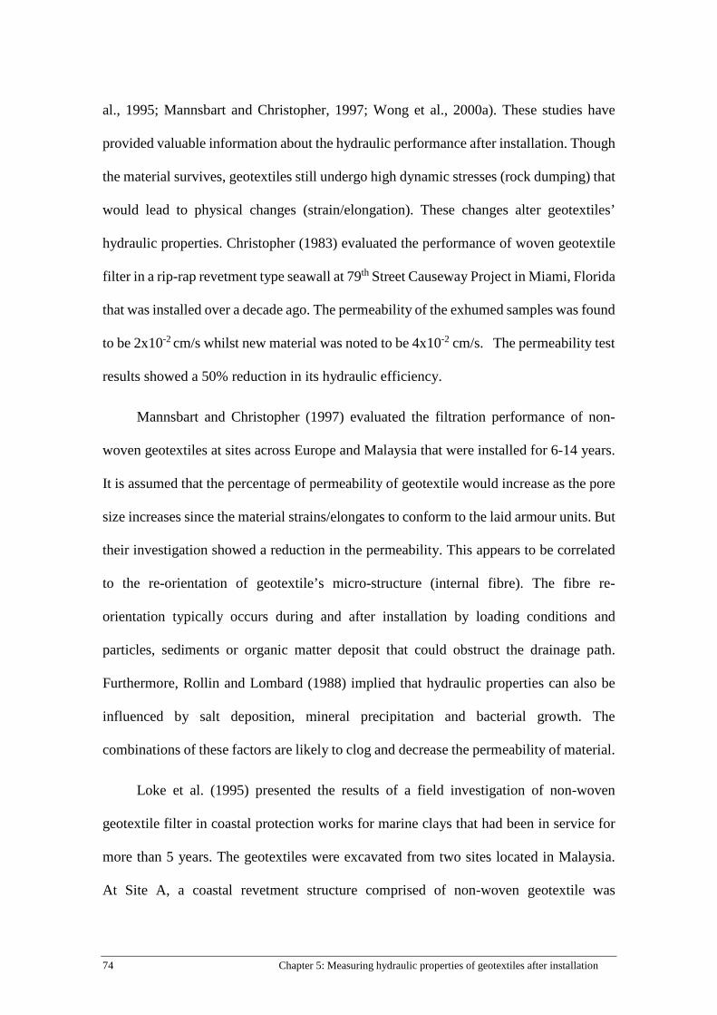
74 Chapter 5: Measuring hydraulic properties of geotextiles after installation
al., 1995; Mannsbart and Christopher, 1997; Wong et al., 2000a). These studies have
provided valuable information about the hydraulic performance after installation. Though
the material survives, geotextiles still undergo high dynamic stresses (rock dumping) that
would lead to physical changes (strain/elongation). These changes alter geotextiles’
hydraulic properties. Christopher (1983) evaluated the performance of woven geotextile
filter in a rip-rap revetment type seawall at 79th Street Causeway Project in Miami, Florida
that was installed over a decade ago. The permeability of the exhumed samples was found
to be 2x10⁻² cm/s whilst new material was noted to be 4x10⁻² cm/s. The permeability test
results showed a 50% reduction in its hydraulic efficiency.
Mannsbart and Christopher (1997) evaluated the filtration performance of non-
woven geotextiles at sites across Europe and Malaysia that were installed for 6-14 years.
It is assumed that the percentage of permeability of geotextile would increase as the pore
size increases since the material strains/elongates to conform to the laid armour units. But
their investigation showed a reduction in the permeability. This appears to be correlated
to the re-orientation of geotextile’s micro-structure (internal fibre). The fibre re-
orientation typically occurs during and after installation by loading conditions and
particles, sediments or organic matter deposit that could obstruct the drainage path.
Furthermore, Rollin and Lombard (1988) implied that hydraulic properties can also be
influenced by salt deposition, mineral precipitation and bacterial growth. The
combinations of these factors are likely to clog and decrease the permeability of material.
Loke et al. (1995) presented the results of a field investigation of non-woven
geotextile filter in coastal protection works for marine clays that had been in service for
more than 5 years. The geotextiles were excavated from two sites located in Malaysia.
At Site A, a coastal revetment structure comprised of non-woven geotextile was
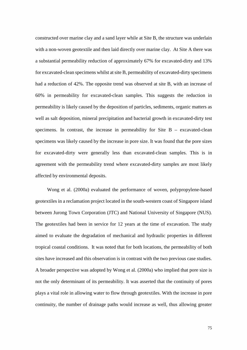
75
constructed over marine clay and a sand layer while at Site B, the structure was underlain
with a non-woven geotextile and then laid directly over marine clay. At Site A there was
a substantial permeability reduction of approximately 67% for excavated-dirty and 13%
for excavated-clean specimens whilst at site B, permeability of excavated-dirty specimens
had a reduction of 42%. The opposite trend was observed at site B, with an increase of
60% in permeability for excavated-clean samples. This suggests the reduction in
permeability is likely caused by the deposition of particles, sediments, organic matters as
well as salt deposition, mineral precipitation and bacterial growth in excavated-dirty test
specimens. In contrast, the increase in permeability for Site B – excavated-clean
specimens was likely caused by the increase in pore size. It was found that the pore sizes
for excavated-dirty were generally less than excavated-clean samples. This is in
agreement with the permeability trend where excavated-dirty samples are most likely
affected by environmental deposits.
Wong et al. (2000a) evaluated the performance of woven, polypropylene-based
geotextiles in a reclamation project located in the south-western coast of Singapore island
between Jurong Town Corporation (JTC) and National University of Singapore (NUS).
The geotextiles had been in service for 12 years at the time of excavation. The study
aimed to evaluate the degradation of mechanical and hydraulic properties in different
tropical coastal conditions. It was noted that for both locations, the permeability of both
sites have increased and this observation is in contrast with the two previous case studies.
A broader perspective was adopted by Wong et al. (2000a) who implied that pore size is
not the only determinant of its permeability. It was asserted that the continuity of pores
plays a vital role in allowing water to flow through geotextiles. With the increase in pore
continuity, the number of drainage paths would increase as well, thus allowing greater

76 Chapter 5: Measuring hydraulic properties of geotextiles after installation
flow of water passing through the geotextile. This view is supported by Rawal et al.
(2010b) who asserted the hydraulic efficiency of geotextiles is greatly influenced by the
width and depth of pores.
Undoubtedly, long term studies on hydraulic performance have aided the task of
selecting the appropriate opening size to meet the filtration criteria. But, research work
focuses on the long term observations; hence it would be difficult to isolate the influence
of installation damage itself as there are a great number of environmental factors
involved. Watn and Chew (2002) point out that there is a lack of knowledge for designers
and engineers to know whether a geotextile that is designed for filtration function can
survive the installation process without being damaged. Berendsen (1996) suggests that
a geotextile filter designed for hydraulic structures should fulfil the filtration criteria but
must have sufficient mechanical robustness to resist damage during installation
particularly the dumping of amour units. The ideal approach would be to perform large
scale dumping tests in real field conditions and evaluate the consequences of the damage
on immediately recovered samples. However, there are limited studies (Bräu, 1996;
Diederich, 2000; Paula et al., 2008) that select this study approach as such investigations
requires large setup, is costly and time-consuming. A universal adoptable method would
be most favourable with controlled damage simulation that closely replicates the
predominant installation conditions of geotextile in the field.
Several authors (Carneiro et al., 2013; Paula et al., 2004; Rosete et al.,
2013) have investigated the effect of installation damage on geotextiles using standard
laboratory tests methodology for damage simulation. Carneiro et al. (2013) evaluated the
short term behaviour (tensile and hydraulic) of five non-woven polypropylene geotextiles
that were placed between two layers of granular material and subjected to dynamic
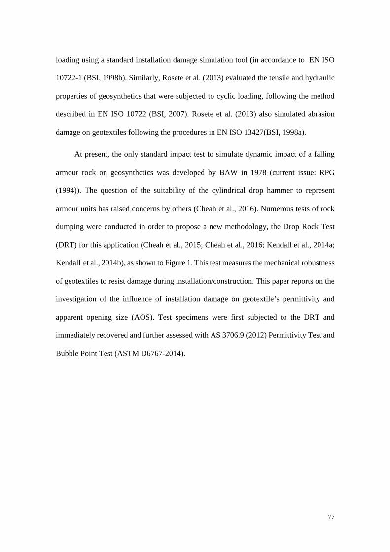
77
loading using a standard installation damage simulation tool (in accordance to EN ISO
10722-1 (BSI, 1998b). Similarly, Rosete et al. (2013) evaluated the tensile and hydraulic
properties of geosynthetics that were subjected to cyclic loading, following the method
described in EN ISO 10722 (BSI, 2007). Rosete et al. (2013) also simulated abrasion
damage on geotextiles following the procedures in EN ISO 13427(BSI, 1998a).
At present, the only standard impact test to simulate dynamic impact of a falling
armour rock on geosynthetics was developed by BAW in 1978 (current issue: RPG
(1994)). The question of the suitability of the cylindrical drop hammer to represent
armour units has raised concerns by others (Cheah et al., 2016). Numerous tests of rock
dumping were conducted in order to propose a new methodology, the Drop Rock Test
(DRT) for this application (Cheah et al., 2015; Cheah et al., 2016; Kendall et al., 2014a;
Kendall et al., 2014b), as shown to Figure 1. This test measures the mechanical robustness
of geotextiles to resist damage during installation/construction. This paper reports on the
investigation of the influence of installation damage on geotextile’s permittivity and
apparent opening size (AOS). Test specimens were first subjected to the DRT and
immediately recovered and further assessed with AS 3706.9 (2012) Permittivity Test and
Bubble Point Test (ASTM D6767-2014).
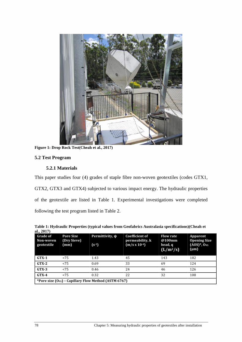
78 Chapter 5: Measuring hydraulic properties of geotextiles after installation
Figure 1: Drop Rock Test(Cheah et al., 2017)
5.2 Test Program
5.2.1 Materials
This paper studies four (4) grades of staple fibre non-woven geotextiles (codes GTX1,
GTX2, GTX3 and GTX4) subjected to various impact energy. The hydraulic properties
of the geotextile are listed in Table 1. Experimental investigations were completed
following the test program listed in Table 2.
Table 1: Hydraulic Properties (typical values from Geofabrics Australasia specifications)(Cheah et al., 2017)
Grade of Non-woven geotextile
Pore Size (Dry Sieve) (mm)
Permittivity, ψ (s-1)
Coefficient of permeability, k (m/s x 10-4)
Flow rate @100mm head, q (L/m2/s)
Apparent Opening Size (AOS)*, O95
(µm)
GTX-1 <75 1.43 45 143 182 GTX-2 <75 0.69 33 69 124 GTX-3 <75 0.46 24 46 126 GTX-4 <75 0.32 22 32 108 *Pore size (O95) – Capillary Flow Method (ASTM 6767)
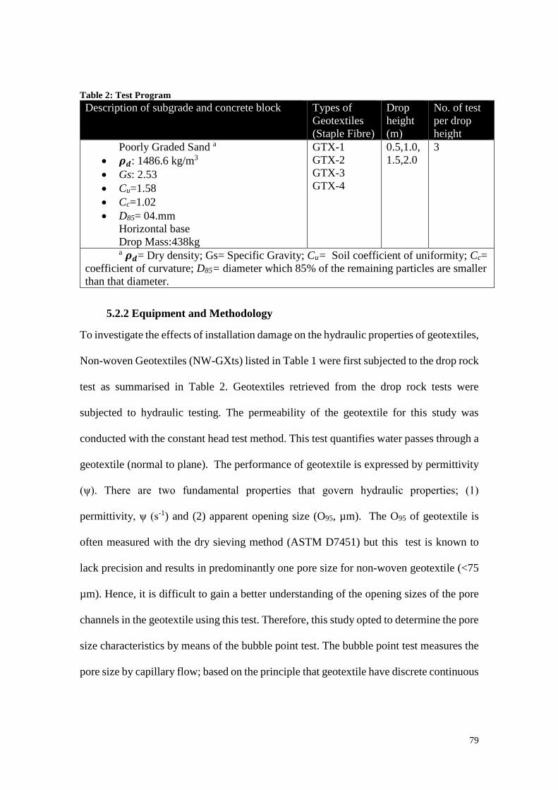
79
Table 2: Test Program Description of subgrade and concrete block Types of
Geotextiles (Staple Fibre)
Drop height (m)
No. of test per drop height
Poorly Graded Sand a
• 𝝆𝝆𝒅𝒅: 1486.6 kg/m3 • Gs: 2.53 • Cu=1.58 • Cc=1.02 • D85= 04.mm
Horizontal base Drop Mass:438kg
GTX-1 GTX-2 GTX-3 GTX-4
0.5,1.0,1.5,2.0
3
a 𝝆𝝆𝒅𝒅= Dry density; Gs= Specific Gravity; Cu= Soil coefficient of uniformity; Cc= coefficient of curvature; D85= diameter which 85% of the remaining particles are smaller than that diameter.
5.2.2 Equipment and Methodology
To investigate the effects of installation damage on the hydraulic properties of geotextiles,
Non-woven Geotextiles (NW-GXts) listed in Table 1 were first subjected to the drop rock
test as summarised in Table 2. Geotextiles retrieved from the drop rock tests were
subjected to hydraulic testing. The permeability of the geotextile for this study was
conducted with the constant head test method. This test quantifies water passes through a
geotextile (normal to plane). The performance of geotextile is expressed by permittivity
(ψ). There are two fundamental properties that govern hydraulic properties; (1)
permittivity, ψ (s-1) and (2) apparent opening size (O95, µm). The O95 of geotextile is
often measured with the dry sieving method (ASTM D7451) but this test is known to
lack precision and results in predominantly one pore size for non-woven geotextile (<75
µm). Hence, it is difficult to gain a better understanding of the opening sizes of the pore
channels in the geotextile using this test. Therefore, this study opted to determine the pore
size characteristics by means of the bubble point test. The bubble point test measures the
pore size by capillary flow; based on the principle that geotextile have discrete continuous

80 Chapter 5: Measuring hydraulic properties of geotextiles after installation
pore from one side to the other side of the geotextile. Detailed procedures for the relevant
test methods are described in the following sections.
5.2.2.1 Drop Rock Test
To simulate installation conditions on site where ripraps, stones or rock armour are
dropped above geotextile during construction of coastal protection structure, the Drop
Rock Test was utilised (Cheah et al., 2016). Tests were carried out by releasing a 90o
acute tip concrete block of 438 kg at a specified drop height onto a geotextile that was
laid above the subgrade with fixed edge boundary (Fig. 1). The elongation of the DRT
samples that undergo various impact energies were measured and immediately recovered
for Permittivity Test and Bubble Point Test. Elongations were measured against 6 grid
squares which were initially 300mm (50mm per square) from the point of impact (Fig.
2).
Figure 2: Elongation measurement(Cheah et al., 2017)
5.2.2.2 Hydraulic Tests
5.2.2.2.1 Constant Head Test The retrieved samples were further assessed with Permittivity Test, in accordance with
AS3706.9 (2012). The location of retrieved samples (edge, partially damage and critical
damage) is illustrated in Figure 3. It was assumed that the edge materials did not

81
experience any damage caused by the released concrete block and thus were considered
as control specimens. Comparisons were made between control and strained specimens
(partially and critical damage), refer to Figure 4. In the constant head method, a single
layer of specimen were subjected to unidirectional flow of water (normal to plane) with
headloss ranging between 5-25mm. Figure 5 illustrates the constant head apparatus. The
results were expressed in terms of permittivity 𝜓𝜓 (s-1), coefficient of permittivity, k (m/s-1
x10-4), headloss, ∆ℎ (m) and flow rate, q (m3/s) was determined. The term permittivity
determined from the following equation:
𝜓𝜓 = 𝑞𝑞 𝑛𝑛𝐴𝐴∆ℎ� (1)
where 𝜓𝜓 is the permittivity of specimen, in reciprocal seconds, q is the flow through the
specimen, n is the number of layers of specimen, A is the exposed cross-sectional area in
square meters and ∆ℎ is the headloss, in meters. The coefficient of permittivity, k was
determined from the following equation:
𝑘𝑘 = 𝜓𝜓 × 𝑡𝑡 (2)
where 𝑘𝑘 is the coefficient of permittivity of specimen in meters per second. Results
presented in Figure 8 also include the change in permittivity in percentage term (%)
between control and critically damaged specimens,
𝑃𝑃𝑒𝑒𝑒𝑒𝑒𝑒𝑒𝑒𝑛𝑛𝑡𝑡𝑒𝑒𝑚𝑚𝑒𝑒 𝑒𝑒ℎ𝑒𝑒𝑛𝑛𝑚𝑚𝑒𝑒 𝑖𝑖𝑛𝑛 𝑃𝑃𝑒𝑒𝑒𝑒𝑚𝑚𝑖𝑖𝑡𝑡𝑡𝑡𝑖𝑖𝑃𝑃𝑖𝑖𝑡𝑡𝑃𝑃 (%) = (𝑃𝑃𝐶𝐶𝐶𝐶 − 𝑃𝑃𝐶𝐶)𝑃𝑃𝐶𝐶� ∗ 100%
(3)
where 𝑃𝑃𝐶𝐶𝐶𝐶 is the mean permittivity of the critically damaged samples and 𝑃𝑃𝐶𝐶is the mean
permittivity of control specimens.

82 Chapter 5: Measuring hydraulic properties of geotextiles after installation
Figure 3: Location of recovered samples(Cheah et al., 2017)
Edge (Control)
Partially Damaged
Critical Damaged
Figure 4: Test Specimens (Cheah et al., 2017)
5.2.2.2.2 Bubble Point Test Specimens were further examined with the Bubble Point Test in accordance to ASTM
D6767-2014. The bubble point test determines the apparent opening size (O95, µm) as a
EDGE
PARTIAL
CRITICAL
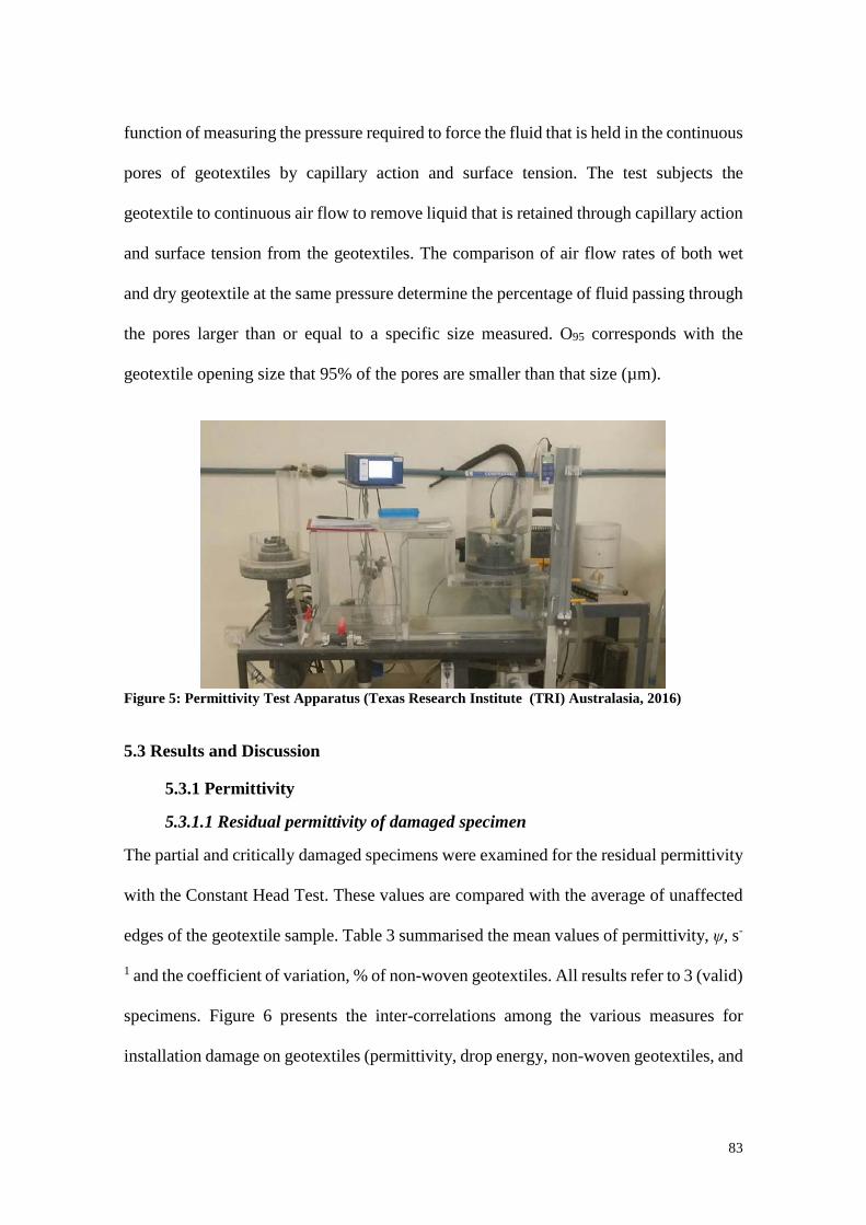
83
function of measuring the pressure required to force the fluid that is held in the continuous
pores of geotextiles by capillary action and surface tension. The test subjects the
geotextile to continuous air flow to remove liquid that is retained through capillary action
and surface tension from the geotextiles. The comparison of air flow rates of both wet
and dry geotextile at the same pressure determine the percentage of fluid passing through
the pores larger than or equal to a specific size measured. O95 corresponds with the
geotextile opening size that 95% of the pores are smaller than that size (µm).
Figure 5: Permittivity Test Apparatus (Texas Research Institute (TRI) Australasia, 2016)
5.3 Results and Discussion
5.3.1 Permittivity
5.3.1.1 Residual permittivity of damaged specimen
The partial and critically damaged specimens were examined for the residual permittivity
with the Constant Head Test. These values are compared with the average of unaffected
edges of the geotextile sample. Table 3 summarised the mean values of permittivity, ψ, s-
1 and the coefficient of variation, % of non-woven geotextiles. All results refer to 3 (valid)
specimens. Figure 6 presents the inter-correlations among the various measures for
installation damage on geotextiles (permittivity, drop energy, non-woven geotextiles, and
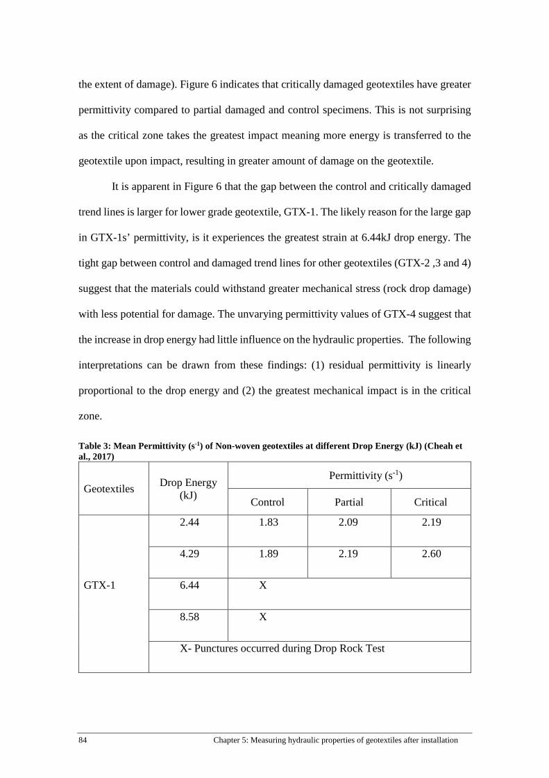
84 Chapter 5: Measuring hydraulic properties of geotextiles after installation
the extent of damage). Figure 6 indicates that critically damaged geotextiles have greater
permittivity compared to partial damaged and control specimens. This is not surprising
as the critical zone takes the greatest impact meaning more energy is transferred to the
geotextile upon impact, resulting in greater amount of damage on the geotextile.
It is apparent in Figure 6 that the gap between the control and critically damaged
trend lines is larger for lower grade geotextile, GTX-1. The likely reason for the large gap
in GTX-1s’ permittivity, is it experiences the greatest strain at 6.44kJ drop energy. The
tight gap between control and damaged trend lines for other geotextiles (GTX-2 ,3 and 4)
suggest that the materials could withstand greater mechanical stress (rock drop damage)
with less potential for damage. The unvarying permittivity values of GTX-4 suggest that
the increase in drop energy had little influence on the hydraulic properties. The following
interpretations can be drawn from these findings: (1) residual permittivity is linearly
proportional to the drop energy and (2) the greatest mechanical impact is in the critical
zone.
Table 3: Mean Permittivity (s-1) of Non-woven geotextiles at different Drop Energy (kJ) (Cheah et al., 2017)
Geotextiles Drop Energy (kJ)
Permittivity (s-1)
Control Partial Critical
GTX-1
2.44 1.83 2.09 2.19
4.29 1.89 2.19 2.60
6.44 X
8.58 X
X- Punctures occurred during Drop Rock Test

85
GTX-2
2.44 1.02 1.00 1.09
4.29 0.95 1.02 1.13
6.44 1.00 1.06 1.11
8.58 0.99 1.15 1.29
GTX-3
2.44 0.66 0.75 0.79
4.29 0.73 0.79 0.89
6.44 0.67 0.81 0.903
8.58 0.76 0.80 0.93
GTX-4
2.44 0.37 0.41 0.43
4.29 0.37 0.38 0.43
6.44 0.41 0.43 0.47
8.58 0.40 0.40 0.46
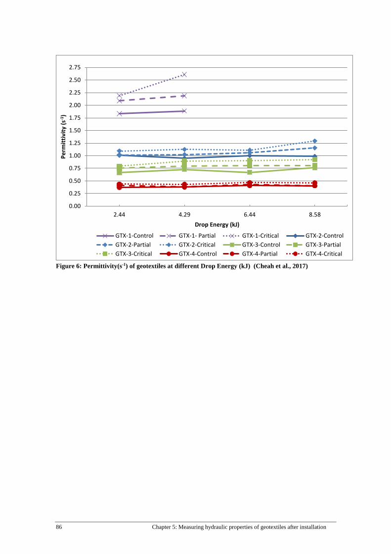
86 Chapter 5: Measuring hydraulic properties of geotextiles after installation
Figure 6: Permittivity(s-1) of geotextiles at different Drop Energy (kJ) (Cheah et al., 2017)
0.00
0.25
0.50
0.75
1.00
1.25
1.50
1.75
2.00
2.25
2.50
2.75
2.44 4.29 6.44 8.58
Perm
ittiv
ity (s
-1)
Drop Energy (kJ)
GTX-1-Control GTX-1- Partial GTX-1-Critical GTX-2-ControlGTX-2-Partial GTX-2-Critical GTX-3-Control GTX-3-PartialGTX-3-Critical GTX-4-Control GTX-4-Partial GTX-4-Critical

87
5.3.1.2 Relationship between permittivity and drop energy
Figure 7: Linear relationship between permittivity and drop energy of critically damaged geotextiles (Cheah et al., 2017)
Figure 7 presents the relationship between permittivity and drop energy before and after
rock drop damage tests. The data projected a linear relationship between permittivity of
geotextile and applied drop energy. From Figure 7, after induced damage the rate of
permittivity per drop energy of GTX-4 remains practically unchanged (0.009 s-1/kJ). For
both GTX-2 and GTX-3, the gradient of both trend lines is very similar to each other
(0.291 s-1/kJ and 0.267 s-1/kJ, respectively). For GTX-1, the permittivity increases at a
rate of 0.17 s-1 per drop energy (kJ), the highest rate of change compared to other
geotextile samples (GTX-2, 3, and 4). It is apparent in Figure 7 that the better the grade
of the geotextile, the better the ability of the material to withstand rock drop damage.
5.3.1.3 Effects on the permittivity and apparent opening size (O95)
Figure 8 represents the relationships obtained from the hydraulic test after semi-
laboratory damage tests (Drop Rock Test). The data correspond to the percentage change
y = 0.1723x + 1.8335
y = 0.0297x + 0.9927
y = 0.0261x + 0.73
y = 0.0087x + 0.3985
0.00
0.50
1.00
1.50
2.00
2.50
3.00
-1.00 1.00 3.00 5.00 7.00 9.00
Perm
ittiv
ity (s
-1)
Drop Energy (kJ)
GTX-1 GTX-2 GTX-3 GTX-4

88 Chapter 5: Measuring hydraulic properties of geotextiles after installation
in permittivity and O95 of critically damaged specimens to the corresponding drop
energies. Figure 8 shows that, as expected, the permittivity and O95 increases with drop
energy. For GTX-1 (Figure 8a) both curves projected the expected behaviour and for
GTX-4 (Figure 8d) the permittivity and O95 remained unchanged after rock drop damage.
For both GTX-2 (Figure 8b) and GTX-3 (Figure 8c), the change in permittivity
corresponds exactly with the change in O95 but atypical observation is noted at 6.44kJ.
After rock drop damage at 6.44kJ, the permittivity of GTX-2 decreased about 18% when
compared with the undamaged sample. This is 20% less than the change in permittivity
at the lower drop energy, 4.29kJ. This is a result of two factors: the number of tested
specimen is small (3); and the size of the tested specimen is small and may not fully
represent the greatest extent of damage. For GTX-3 the permittivity and O95 increased
35% and 18% respectively after rock drop damage at 6.44kJ, whereas at the highest drop
energy, 8.58kJ, the permittivity and O95 values decreased to 22% and 13% respectively.
It would be expected that the permittivity and the O95 of the material would increase
because the induced rock drop damage, 8.58kJ is more severe than at 6.44kJ. This is likely
the result of the complex porous structure of the fibrous network in a geotextile and the
number of tested specimen is small (3). The fibre re-orientation in GTX-3 after rock drop
damage at 6.44kJ affected more free paths of the permeant flow through the geotextile
resulting in higher permittivity and O95 values than at 8.58kJ. This is consistent with the
finding from Rawal (2010) in that the alignment of fibres in the geotextiles significantly
affects the pore size in non-woven geotextiles.
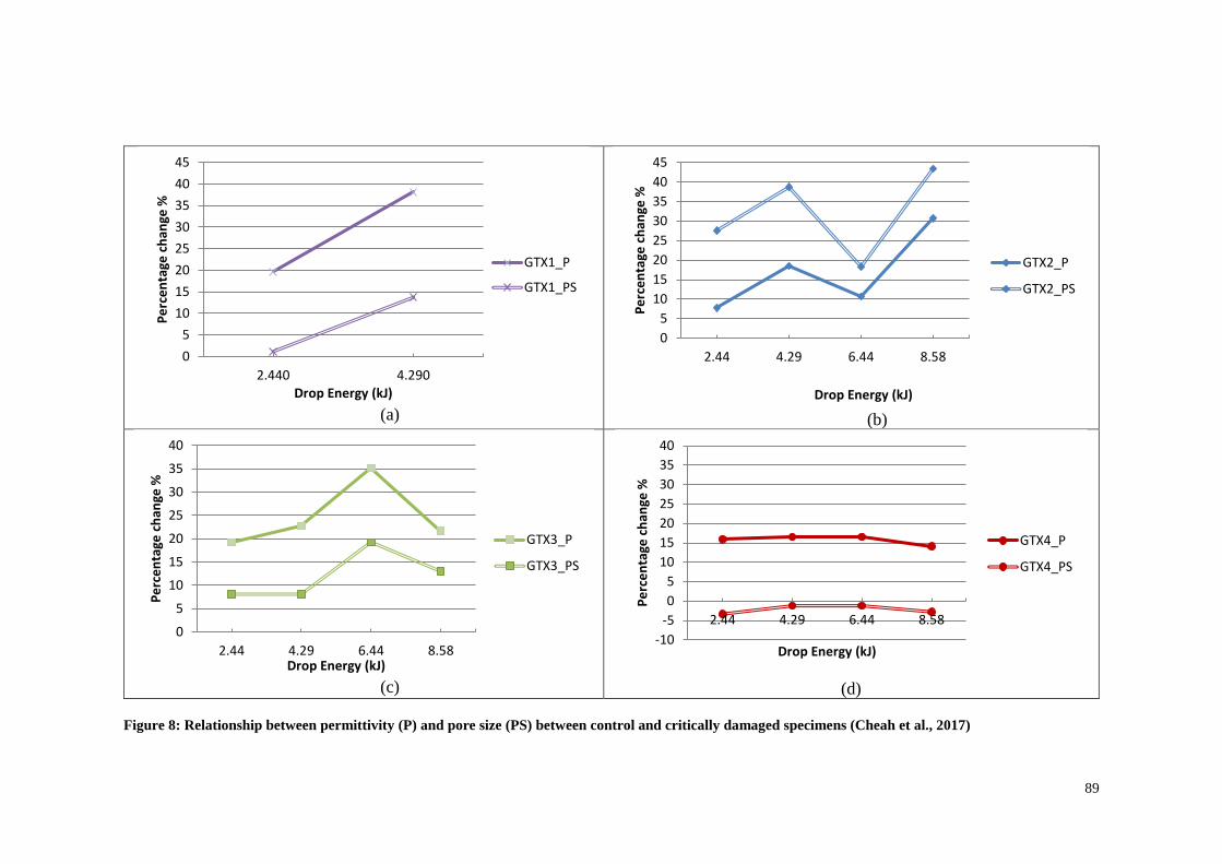
89
(a)
(b)
(c)
(d)
Figure 8: Relationship between permittivity (P) and pore size (PS) between control and critically damaged specimens (Cheah et al., 2017)
05
1015202530354045
2.440 4.290
Perc
enta
ge c
hang
e %
Drop Energy (kJ)
GTX1_P
GTX1_PS
05
1015202530354045
2.44 4.29 6.44 8.58
Perc
enta
ge c
hang
e %
Drop Energy (kJ)
GTX2_P
GTX2_PS
0
5
10
15
20
25
30
35
40
2.44 4.29 6.44 8.58
Perc
enta
ge c
hang
e %
Drop Energy (kJ)
GTX3_P
GTX3_PS
-10-505
10152025303540
2.44 4.29 6.44 8.58Pe
rcen
tage
cha
nge
%Drop Energy (kJ)
GTX4_P
GTX4_PS

90 Chapter 5: Measuring hydraulic properties of geotextiles after installation
5.3.1.4 Coefficient of permittivity, k
From the test results, the coefficient of permittivity was determined with Equation 2. The
majority of the design standards require the minimum permittivity of the geotextile in
relation to the permittivity of the adjacent soil to be
𝑘𝑘𝑔𝑔𝑔𝑔𝑔𝑔𝑔𝑔𝑔𝑔𝑔𝑔𝑔𝑔𝑖𝑖𝑔𝑔𝑔𝑔 ≥ 10 𝑘𝑘 𝑠𝑠𝑔𝑔𝑖𝑖𝑔𝑔
where 𝑘𝑘𝑔𝑔𝑔𝑔𝑔𝑔𝑔𝑔𝑔𝑔𝑔𝑔𝑔𝑔𝑖𝑖𝑔𝑔𝑔𝑔 and 𝑘𝑘 𝑠𝑠𝑔𝑔𝑖𝑖𝑔𝑔 are the coefficient of permeability of the geotextile and soil,
respectively (Heibaum, 2016). Table 4 presents the mean coefficient of permeability of
critically damaged specimen at various drop energies. In this study, the coefficient of
permeability of subgrade is 2.7 m/s × 10−4 which limits 𝑘𝑘𝑔𝑔𝑔𝑔𝑔𝑔𝑔𝑔𝑔𝑔𝑔𝑔𝑔𝑔𝑖𝑖𝑔𝑔𝑔𝑔 to 27 m/s × 10−4.
Given the case of very permeable soil, Heibaum (2016) further suggests that 𝑘𝑘𝑔𝑔𝑔𝑔𝑔𝑔𝑔𝑔𝑔𝑔𝑔𝑔𝑔𝑔𝑖𝑖𝑔𝑔𝑔𝑔 ≥
𝑘𝑘 𝑠𝑠𝑔𝑔𝑖𝑖𝑔𝑔 may be sufficient. Closer inspection of Table 5, shows 𝑘𝑘𝑔𝑔𝑔𝑔𝑔𝑔𝑔𝑔𝑔𝑔𝑔𝑔𝑔𝑔𝑖𝑖𝑔𝑔𝑔𝑔 for all four grade
of geotextiles were greater than 27 m/s × 10−4, the smallest k value (GTX4- 4.29kJ),
37.67 m/s × 10−4still achieves the minimum requirement. The hydraulic tests showed an
increase of coefficient of permittivity of damaged specimen as compared to the control
geotextiles ranging from a factor of 1.4 to 3.3, and their coefficient of permittivity
exceeded the coefficient of permittivity of the subgrade tested in Table 2.
Table 4: Coefficient of permittivity, k (m/s x10-4) (Cheah et al., 2017)
Coefficient of permittivity, k (m/s x 10-4)
Geotextiles
Drop Energy (kJ)
GTX-1 GTX-2 GTX-3 GTX-4
2.44 87.68 72.62 54.65 40.50
4.29 82.74 79.26 66.29 37.67
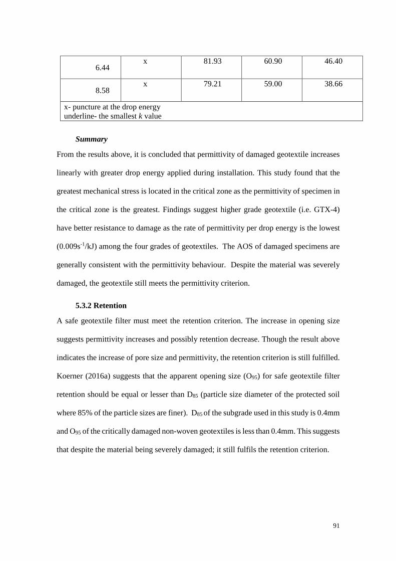
91
6.44 x 81.93 60.90 46.40
8.58 x 79.21 59.00 38.66
x- puncture at the drop energy underline- the smallest k value
Summary
From the results above, it is concluded that permittivity of damaged geotextile increases
linearly with greater drop energy applied during installation. This study found that the
greatest mechanical stress is located in the critical zone as the permittivity of specimen in
the critical zone is the greatest. Findings suggest higher grade geotextile (i.e. GTX-4)
have better resistance to damage as the rate of permittivity per drop energy is the lowest
(0.009s-1/kJ) among the four grades of geotextiles. The AOS of damaged specimens are
generally consistent with the permittivity behaviour. Despite the material was severely
damaged, the geotextile still meets the permittivity criterion.
5.3.2 Retention
A safe geotextile filter must meet the retention criterion. The increase in opening size
suggests permittivity increases and possibly retention decrease. Though the result above
indicates the increase of pore size and permittivity, the retention criterion is still fulfilled.
Koerner (2016a) suggests that the apparent opening size (O95) for safe geotextile filter
retention should be equal or lesser than D85 (particle size diameter of the protected soil
where 85% of the particle sizes are finer). D85 of the subgrade used in this study is 0.4mm
and O95 of the critically damaged non-woven geotextiles is less than 0.4mm. This suggests
that despite the material being severely damaged; it still fulfils the retention criterion.

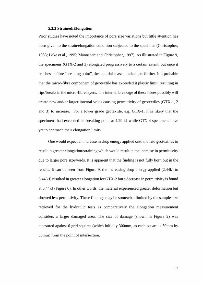
93
5.3.3 Strained/Elongation
Prior studies have noted the importance of pore size variations but little attention has
been given to the strain/elongation condition subjected to the specimen (Christopher,
1983; Loke et al., 1995; Mannsbart and Christopher, 1997). As illustrated in Figure 9,
the specimens (GTX-2 and 3) elongated progressively to a certain extent, but once it
reaches its fibre “breaking point”, the material ceased to elongate further. It is probable
that the micro-fibre component of geotextile has exceeded it plastic limit, resulting in
rips/breaks in the micro-fibre layers. The internal breakage of these fibres possibly will
create new and/or larger internal voids causing permittivity of geotextiles (GTX-1, 2
and 3) to increase. For a lower grade geotextile, e.g. GTX-1, it is likely that the
specimens had exceeded its breaking point at 4.29 kJ while GTX-4 specimens have
yet to approach their elongation limits.
One would expect an increase in drop energy applied onto the laid geotextiles to
result in greater elongation/straining which would result in the increase in permittivity
due to larger pore size/voids. It is apparent that the finding is not fully born out in the
results. It can be seen from Figure 9, the increasing drop energy applied (2.44kJ to
6.44 kJ) resulted in greater elongation for GTX-2 but a decrease in permittivity is found
at 6.44kJ (Figure 6). In other words, the material experienced greater deformation but
showed less permittivity. These findings may be somewhat limited by the sample size
retrieved for the hydraulic tests as comparatively the elongation measurement
considers a larger damaged area. The size of damage (shown in Figure 2) was
measured against 6 grid squares (which initially 300mm, as each square is 50mm by
50mm) from the point of intersection.
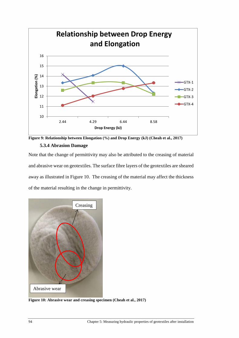
94 Chapter 5: Measuring hydraulic properties of geotextiles after installation
Figure 9: Relationship between Elongation (%) and Drop Energy (kJ) (Cheah et al., 2017)
5.3.4 Abrasion Damage
Note that the change of permittivity may also be attributed to the creasing of material
and abrasive wear on geotextiles. The surface fibre layers of the geotextiles are sheared
away as illustrated in Figure 10. The creasing of the material may affect the thickness
of the material resulting in the change in permittivity.
Figure 10: Abrasive wear and creasing specimen (Cheah et al., 2017)
10
11
12
13
14
15
16
2.44 4.29 6.44 8.58
Elon
gatio
n (%
)
Drop Energy (kJ)
Relationship between Drop Energyand Elongation
GTX-1
GTX-2
GTX-3
GTX-4
Creasing
Abrasive wear
95
5.4 Limitations
The ability to generalise these results is subject to certain limitations. For instance, this
study only takes into account clean samples, whereas in field case studies, exhumed
samples are often dirty and clogged. The current study is based on a small sample size;
further work needs to be carried out to provide more definitive evidence. The
conventional approach to evaluate the permeability of material is the use of water
which is free from turbidity, ions, foreign matter and microorganism; whilst permeant
in a geotextile filter design would be different.
5.5 Conclusion
The present study was designed to determine the hydraulic properties of geotextiles
after installation. The investigation has shown the greater the drop energy applied, the
increase in permittivity of geotextile is greater. Findings suggest for damaged samples
(critical and partial) have greater permittivity than control specimens and the increase
could extent up to 45% during installation. Critically damaged specimens in the critical
zone were subjected to the greatest impact load; they experience the severest form of
damage caused by the acute 90o tip of the concrete block. Because of the impact, the
material undergoes strain/elongation and the opening size of the material increases.
Findings also indicate that the increase in permittivity and opening size of the material
still fulfils the permittivity and retention criterion for an effective geotextile filter. The
opening size of all four grades of non-woven geotextiles is less than the D85 of the
subgrade that was underlain beneath the geotextile. The apparent opening size (O95)
characteristics of critically damaged samples are consistent with the permittivity trend
of geotextiles at varying drop energies. The results of this investigation show that the
relationship between elongation of geotextile and drop energy may not be directly
proportional. The results suggest that the material is likely to experience strain to a
96 Chapter 5: Measuring hydraulic properties of geotextiles after installation
certain extent and once its micro-structure approaches breaking point, the material
ceased to elongate further and is on the verge of puncturing. Barring a puncture in the
geotextile, the rock drop damage observed did not significantly affect the hydraulic
performance (permittivity and retention criterion) of the geotextile. From a design
perspective, the most important outcome is the development of the linear relationship
chart which gauges the amount of damage (in terms of permittivity) prior construction.
It is economical and effective approach as the preliminary design of the coastal
structures is optimised when engineers and designers can better estimate the amount
of damage on geotextiles upon installation.
Acknowledgements
This study was carried out as part of the first author’s PhD research at Queensland
University of Technology (QUT) in Brisbane and therefore authors would like to
acknowledge QUT Research Training Program (RTP) for providing scholarship to the
first author for her PhD study. Authors express their appreciation to Geofabrics Centre
of Excellence in Gold Coast Australia for providing financial support, test materials
and testing facilities for this study. Finally, authors would like to show their gratitude
to TRI Australasia for providing the testing facility for this study and express thanks
to the technical staffs for sharing insight and expertise that greatly assisted the
research.
Notations
AOS Geotextile Apparent opening size Cc Soil coefficient of curvature (dimensionless) Cu Soil coefficient of uniformity (dimensionless) D85 Soil particle diameter for which 85% in mass of the remaining particles have
smaller diameters than that value (mm) Gs Specific Gravity k Soil coefficient of permeability (m/s) q Flow under a constant 0.1m head of water 𝜌𝜌𝑑𝑑 Dry density of subgrade
97
Ψ Geotextile permittivity (s-1)
References
Abromeit, H., Heibaum, M., 1996. Stressing of geosynthetics during installation and construction on site: Installation of geosynthetics in waterways, Proceedings of the First European Geosynthetics Conference EuroGeo.
Berendsen, E., 1996. Dumping of rock on geotextiles. Geosynthetics: applications, design and construction. Proc. 1st European geosynthetics conference, Maastricht, 1996, 919-924.
Bräu, G., 1996. Damage of Geosynthetics During Installation- Experience from Real Sites and Research Works, in: De Groot, M.B., Den Hoedt, G., Termaat, R.J. (Eds.), Proceedings of the First European Geosythetics Conference- Eurogeo 1. Balkema, Maastricht, Netherlands, pp. 145-150.
BSI, 1998a. EN ISO 13427 (1998) Geotextiles and Geotextile-related Products. Abrasion Damage Simulation (sliding block test), London, UK.
BSI, 1998b. ENV ISO 10722-1 (1998) Geotextiles and Geotextile-related products - Procedure for Simulating Damage During Installation - Part 1: Installation in Granular Materials, London, UK.
BSI, 2007. EN ISO 10722 (2007) Geosynthetics, Index Test Procedure for the Evaluation of Mechanical Damage under Repeated Loading - Damage caused by Granular Material, London, UK.
Carneiro, J.R., Morais, L.M., Moreira, S.P., Lopes, M.L., 2013. Evaluation of the Damages Occurred During the Installation of Non-Woven Geotextiles. Materials Science Forum 730-732, 439-444.
Cheah, C., Gallage, C., Dawes, L., Kendall, P., 2015. Effect of Simulated Rock Dumping on Geotextile, 12th Australia New Zealand Conference on Geomechanics, Wellington, New Zealand.
Cheah, C., Gallage, C., Dawes, L., Kendall, P., 2016. Impact resistance and evaluation of retained strength on geotextiles. Geotextiles and Geomembranes 44, 549-556.
Christopher, B.R., 1983. Evaluation of two geotextile installation in excess of a decade old. Transportation Research Record, 79-88.
Diederich, R., 2000. Evaluation of Installation Damage of Geotextiles. A Correlation to Index Tests. Fifth conferece on Geosynthetics, YiChang, China, 24-31.
Heerten, G., 1980. Long-term experience with the use of synthetic filter fabrics in coastal engineering. Coastal Engineering Proceedings 1.
Heerten, G., 1984. Geotextiles in coastal engineering—25 years experience. Geotextiles and Geomembranes 1, 119-141.
Heibaum, M., 2016. Geotextiles used in filtration, Geotextiles- From Design to Applications. Elsevier, p. 257.
Kendall, P., Austin, R.A., Cheah, C., 2014a. Installation Durability Testing of Revetment Geotextiles, 7th International Congress on Enviromental Geotechnics, Melbourne, Australia.
Kendall , P., Austin, R.A., Cheah , C., Lacey , M., 2014b. Large Scale Controlled Testing of Geotextile Puncture Resistance for Rock Impact, 10th International Conference on Geosynthetics. Deutsche Gesellschaft für Geotechnik e.V., Berlin Germany.
Koerner, R., 2016. Geotextiles: From Design to Applications. Elsevier S&T Frontlist Promotion 2016, GB.
98 Chapter 5: Measuring hydraulic properties of geotextiles after installation
Loke, K.H., Lee, C.H., Lim, C.H., Chin, P.W., 1995. Performance of nonwoven geotextile in coastal protection works with marine clays: a case study. Nonwovens Industry 26, 60-64.
Mannsbart, G., Christopher, B.R., 1997. Long-term performance of nonwoven geotextile filters in five coastal and bank protection projects. Geotextiles and Geomembranes 15, 207-221.
Palmeira, E.M., Tatto, J., 2015. Behaviour of geotextile filters in armoured slopes subjected to the action of waves. Geotextiles and Geomembranes 43, 46-55.
Paula, A.M., Pinho-Lopes, M., Lopes, M.d.L., 2004. Damage during installation laboratory test. Influence of the type of granular material, Proceedings of 3rd of European Geosynthetics Conference, Munich, pp. 603-606.
Paula, A.M., Pinho-Lopes, M., Lopes, M.d.L., 2008. Combined effect of damage during installation and long-term mechanical behavior of geosynthetics, 4th European Geosynthetics Conference.
Pilarczyk, K., 2000. Critical review of geosystems in hydraulics and coastal engineering application, Atti II European Geosynthetics Conference, Bologna, pp. 65-76.
Rawal, A., Shah, T., Anand, S., 2010. Geotextiles: production, properties and performance. Textile Progress 42, 181-226.
Rollin, A., Lombard, G., 1988. Mechanisms affecting long-term filtration behavior of geotextiles. Geotextiles and Geomembranes 7, 119-145.
Rosete, A., Lopes, P.M., Pinho-Lopes, M., Lopes, M.L., 2013. Tensile and hydraulic properties of geosynthetics after mechanical damage and abrasion laboratory tests. Geosynthetics International 20, 358-374.
RPG, 1994. Guidelines for Testing Geotextiles for Navigable Waterways. Bundesanstalt für Wasserbau, Karlsruhe.
Texas Research Institute (TRI) Australasia, 2016. Permittivity Test Apparatus. TRI Australasia Pty Ltd.
Watn, A., Chew, S., 2002. Geosynthetic damage-from laboratory to field, Geosynthetics: State of the Art- Recent Developments. Proceedings of the Seventh International Conference of Geosynthetics,7 ICG held 22-27 September 2002, Nice, France. Volume 4.
Wong, S., Chew, S., Tan, S., Karunaratne, G., Yeo, C., 2000. Geotextile Performance After 12 Years Of Service In Coastal Environment, ISRM International Symposium. International Society for Rock Mechanics.

99
Chapter 6: Investigation of installation robustness of geotextiles in
relation to subgrade moisture condition
Charmaine Cheah, Chaminda Gallage, Les Dawes and Preston Kendall School of Civil Engineering and Built Environment Science and Engineering Faculty Queensland University of Technology Article submitted to: Geotextiles and Geomembranes (under review)
Statement of Contributions of Joint Authorship
The authors listed below have certified that:
1. They meet the criteria for authorship in that they have participated in the conception, execution, or interpretation, of the least that part of the part of the publication in their field of expertise;
2. They take public responsibility for their part of the publication, except for the responsible author who accepts overall responsibility for the publication;
3. There are no authors of the publication to these criteria
4. Potential conflicts of interest have been disclosed to (a) granting bodies, (b) the editor or publisher of journals or other publications, and (c) the head of the responsible academic unit, and
5. They agree to the use of publication in the student’s thesis and its publication on the QUT’s ePrints site consistent with any limitations set by publisher requirements
Cheah, C: (Candidate) Established methodology, data analysis, preparation of tables and figures, writing and compilation of manuscript Signature: Date:
Gallage, C: (Principal supervisor) Supervised and assisted with manuscript compilation, editing and co-author of manuscript Signature: Date:
Dawes, L: (Associate supervisor) Supervised and assisted with manuscript compilation, editing and co-author of manuscript Signature: Date:
Kendall, P: (External supervisor) Editing and co-author of manuscript Signature: Date:
Principal Supervisor Confirmation I have sighted email or other correspondence from all co-authors confirming their certifying authorship. (If Co-authors are not able to sign the form, please forward their email or other correspondence confirming the certifying authorship to the RSC) Name: Signature: Date:

100 Chapter 6: Investigation of installation robustness of geotextiles in relation to subgrade moisture condition
This Chapter is an exact copy submitted to the journal paper above.
Linkage of paper to Research Methodology and Development
This paper examines the influence of site characteristics, specifically subgrade
moisture content on the robustness of geotextiles during installation process. This
research study contributes to a better understanding of how subgrade moisture
condition (natural, field, and saturated) can affect the robustness of geotextile during
installation process. The study suggests that damage found on installed geotextile is
more severe in the case of natural subgrade than in the case of field and saturated
subgrade.
The following objectives were achieved:
Objective 1
• Revised Drop Rock Test methodology to simulate saturated, field and dry subgrade
Objective 3
• Examined the influence of subgrade moisture content on geotextile's robustness during installation
• Assessed the effect of different subgrade moisture content on the retained strength of geotextiles
Objective 6
• Develop chart for geotextiles' robustness against subgrade moisture condition
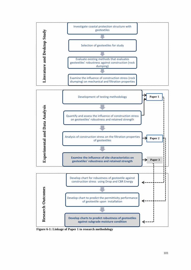
101
Figure 6-1: Linkage of Paper 1 to research methodology
Investigate coastal protection structure with geotextiles
Selection of geotextiles for study
Evaluate existing methods that evaluates geotextiles' robustness against construction (rock
dumping)
Examine the influence of construction stress (rock diumping) on mechanical and filtration properties
Development of testing methodology
Quantify and assess the influence of construction stress on geotextiles' robustness and retained strength
Analysis of construction stress on the filtration properties of geotextiles
Examine the influence of site characteristics on geotextiles' robustness and retained strength
Develop chart for robustness of geotextile against construction stress using Drop and CBR Energy
Develop chart to predict the permittivity performance of geotextile upon installation
Develop charts to predict robustness of geotextiles against subgrade moisture condition
Lite
ratu
re a
nd D
eskt
op S
tudy
E
xper
imen
tal a
nd D
ata
Ana
lysi
s R
esea
rch
Out
com
es
Paper 1
Paper 2
Paper 3
102 Chapter 6: Investigation of installation robustness of geotextiles in relation to subgrade moisture condition
Abstract
Research in relation to installation robustness of geotextiles is important to study.
Previous studies have attempted to evaluate the puncture mechanism of geotextiles
during installations with a new testing method, Drop Rock Test (DRT) developed at
Geofabrics Australasia in 2012. The effects of the drop rock energy and the types of
geotextile on the installation damage of geotextile have been investigated. However,
little research has been carried out on the influence of site characteristics on the
robustness of geotextile during installation procedures. Moisture content, density and
soil type of the subgrade have significant effects on the installation damage of
geotextiles. This paper presents a modified DRT approach to evaluate the installation
damage on geotextile with different subgrade moisture conditions (natural, field and
saturated). Findings of this study conclude that damage on installed geotextile is more
severe in the natural subgrade case than in the saturated subgrade case.
KEYWORDS: Geosynthetics, Rock Drop Test, Subgrade Moisture content,
Installation Damage, CBR Puncture Resistant, Coastal Protection
6.1 Introduction
Since geotextiles have been used in coastal engineering applications, the question of
installation damage has been a key concern. Though installed geotextiles have served
successfully as filters/drainage layer and separators in numerous projects, there are
still cases where the material failed to serve its intended function due to damage
created during installation. Mechanical damage often occurs to a large extent during
installation in the construction process. Literature studies demonstrate that many
authors have attempted to establish the optimal approach to determine the robustness
of geotextile by investigating its mechanical and physical properties (Bräu, 1996;
Carneiro et al., 2013; Elvidge and Raymond, 1999; Heibaum, 2014; Rosete et al.,

103
2013). Robustness refers to geotextiles’ ability to survive (non-puncture) under impact
loads that are applied by dropping rocks onto geotextiles laid on subgrades. Watn and
Chew (2002) reviewed relevant index test methods (mass per unit area, thickness, wide
width tensile, burst resistance, abrasion, CBR plunger, rod plunger, cone drop,
modified cone drop and pendulum impact test) to evaluate geotextiles’ robustness and
examined which of these tests contributed towards the evaluation of damage
susceptibility. They asserted that to date, no laboratory testing method could provide
a comprehensive assessment of the damage susceptibility (Watn and Chew, 2002).
This is attributed to the inability of laboratory testings to fully comprise factors
influencing the damage mechanisms which includes subgrade characteristics,
construction equipment and procedures, and material properties.
The role of site characteristics in geotextiles damage susceptibility has not
received much attention as it is often difficult to characterize the variability in
complete detail. Both Lopes et al. (2001) and Abu-Farsakh et al. (2007) reported that
subgrade characteristics in terms of particles size and distribution, moisture content,
and density have an influence on the soil-geosynthetic interface behaviour. Chew et
al. (1999) further suggested that subgrade properties along with geosynthetic
parameters often play a critical and complex role during geotextiles’ installation in the
field.
Wong et al. (2000b) conducted large scale experiments using the Standard Drop
Test (SDT) method to investigate the robustness of geotextile filter during the
construction of coastal revetments. These authors concluded that density of subgrade
play a significant role in the occurrence of punctures and holes on the geotextile. They
observed that, for the same geotextile and at the same drop height, severe damage is
found in the case of dense sand subgrade than in the case of loose sand subgrade. Wong
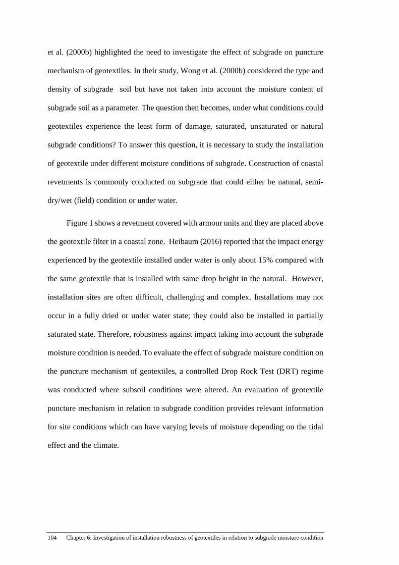
104 Chapter 6: Investigation of installation robustness of geotextiles in relation to subgrade moisture condition
et al. (2000b) highlighted the need to investigate the effect of subgrade on puncture
mechanism of geotextiles. In their study, Wong et al. (2000b) considered the type and
density of subgrade soil but have not taken into account the moisture content of
subgrade soil as a parameter. The question then becomes, under what conditions could
geotextiles experience the least form of damage, saturated, unsaturated or natural
subgrade conditions? To answer this question, it is necessary to study the installation
of geotextile under different moisture conditions of subgrade. Construction of coastal
revetments is commonly conducted on subgrade that could either be natural, semi-
dry/wet (field) condition or under water.
Figure 1 shows a revetment covered with armour units and they are placed above
the geotextile filter in a coastal zone. Heibaum (2016) reported that the impact energy
experienced by the geotextile installed under water is only about 15% compared with
the same geotextile that is installed with same drop height in the natural. However,
installation sites are often difficult, challenging and complex. Installations may not
occur in a fully dried or under water state; they could also be installed in partially
saturated state. Therefore, robustness against impact taking into account the subgrade
moisture condition is needed. To evaluate the effect of subgrade moisture condition on
the puncture mechanism of geotextiles, a controlled Drop Rock Test (DRT) regime
was conducted where subsoil conditions were altered. An evaluation of geotextile
puncture mechanism in relation to subgrade condition provides relevant information
for site conditions which can have varying levels of moisture depending on the tidal
effect and the climate.

105
Figure 1: Geotextile installation (Tessilbrenta, 2013)
This paper aims to assess the robustness of geotextiles against different subgrade
moisture condition. The robustness of four types of non-woven geotextiles were tested
with three different subgrade moisture conditions with the Drop Rock Test. The three
selected of subgrade moistures conditions are natural (1.4%-7%), partially saturated/
field (11%) and saturated (27.8%). After each test, geotextile is first visually observed
and then the specimens are cut out and subjected to CBR puncture test to quantify the
damage.
6.2 Materials and Experimental Description
The experimental set up is similar to the Drop Rock Test (DRT) developed by Cheah
et al. (2016) which simulates installation damage on geotextiles with the placement of
armour rocks with the additional variable of subgrade moisture condition. The test
apparatus consists of an impermeable barrier subgrade containment unit, gantry crane
and concrete blocks. For saturated conditions, the impermeable barrier subgrade
containment unit was constructed by placing a layer of Geosynthetic Clay Liner (GCL)
within the subgrade containment unit. Dimensions and construction of GCL are
illustrated in Figure 2. Upon completion of the GCL installation, sand is shovelled into
the subgrade containment unit. Once the unit is sand filled, the geotextile is laid above
the sand and its’ edges are clamped along the unit to create fixed edge boundary
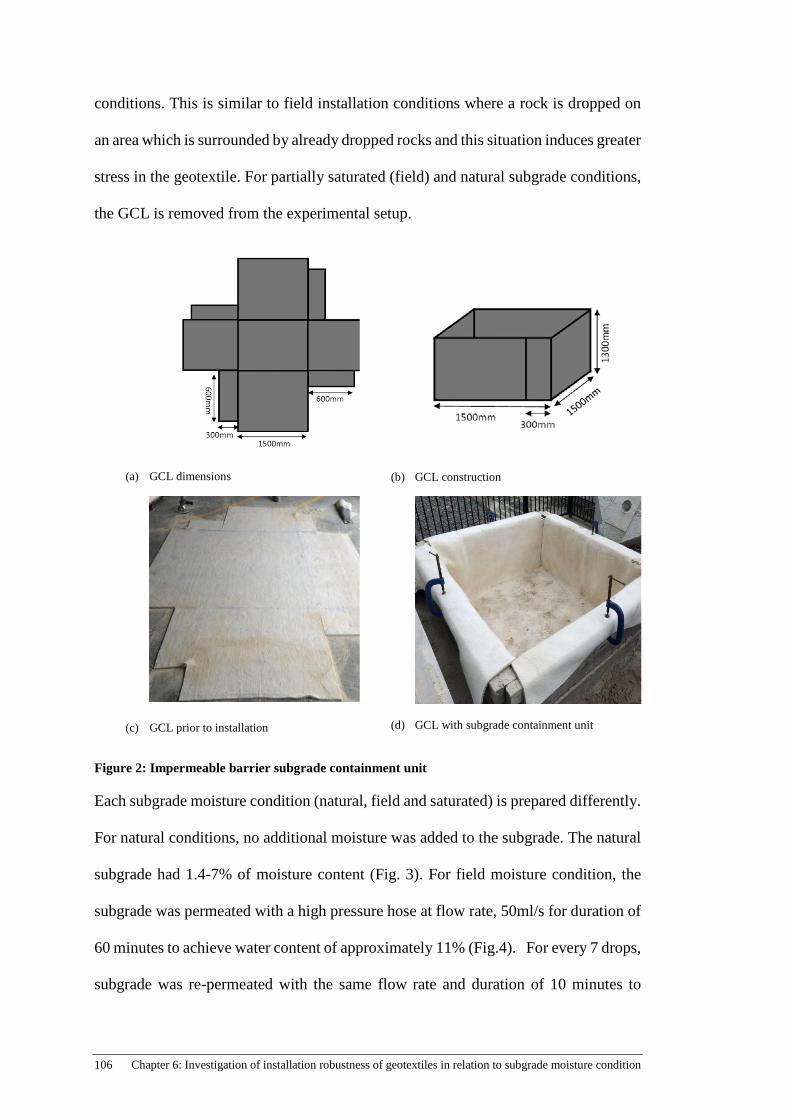
106 Chapter 6: Investigation of installation robustness of geotextiles in relation to subgrade moisture condition
conditions. This is similar to field installation conditions where a rock is dropped on
an area which is surrounded by already dropped rocks and this situation induces greater
stress in the geotextile. For partially saturated (field) and natural subgrade conditions,
the GCL is removed from the experimental setup.
(a) GCL dimensions
(b) GCL construction
(c) GCL prior to installation
(d) GCL with subgrade containment unit
Figure 2: Impermeable barrier subgrade containment unit
Each subgrade moisture condition (natural, field and saturated) is prepared differently.
For natural conditions, no additional moisture was added to the subgrade. The natural
subgrade had 1.4-7% of moisture content (Fig. 3). For field moisture condition, the
subgrade was permeated with a high pressure hose at flow rate, 50ml/s for duration of
60 minutes to achieve water content of approximately 11% (Fig.4). For every 7 drops,
subgrade was re-permeated with the same flow rate and duration of 10 minutes to
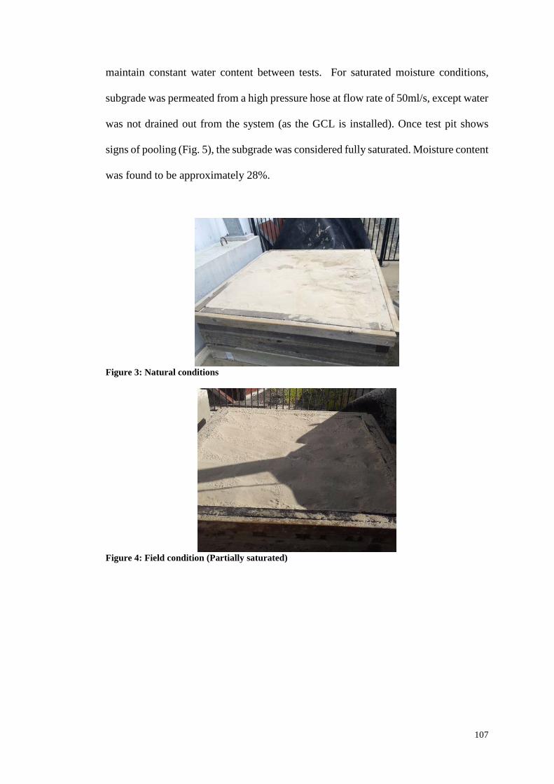
107
maintain constant water content between tests. For saturated moisture conditions,
subgrade was permeated from a high pressure hose at flow rate of 50ml/s, except water
was not drained out from the system (as the GCL is installed). Once test pit shows
signs of pooling (Fig. 5), the subgrade was considered fully saturated. Moisture content
was found to be approximately 28%.
Figure 3: Natural conditions
Figure 4: Field condition (Partially saturated)
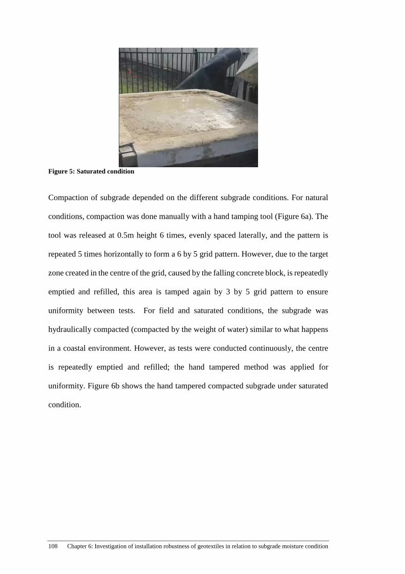
108 Chapter 6: Investigation of installation robustness of geotextiles in relation to subgrade moisture condition
Figure 5: Saturated condition
Compaction of subgrade depended on the different subgrade conditions. For natural
conditions, compaction was done manually with a hand tamping tool (Figure 6a). The
tool was released at 0.5m height 6 times, evenly spaced laterally, and the pattern is
repeated 5 times horizontally to form a 6 by 5 grid pattern. However, due to the target
zone created in the centre of the grid, caused by the falling concrete block, is repeatedly
emptied and refilled, this area is tamped again by 3 by 5 grid pattern to ensure
uniformity between tests. For field and saturated conditions, the subgrade was
hydraulically compacted (compacted by the weight of water) similar to what happens
in a coastal environment. However, as tests were conducted continuously, the centre
is repeatedly emptied and refilled; the hand tampered method was applied for
uniformity. Figure 6b shows the hand tampered compacted subgrade under saturated
condition.

109
(a)
(b)
Figure 6: Compacted subgrade under (a) natural and (b) saturated conditions
Figure 7: DRT apparatus(Cheah et al., 2015; Cheah et al., 2016)
Hand tamping tool

110 Chapter 6: Investigation of installation robustness of geotextiles in relation to subgrade moisture condition
6.2.1 Drop Rock Test
6.2.1.1 Damage during installation (DDI)
A single concrete block (922kg) with a 90o tip is used in the test program to deliver
constant impact energy onto geotextiles for a specified drop height (Fig.7). Geotextiles
with dimensions of 1.8m by 2.0m stencilled with a grid of 50mm by 50mm (Fig. 8),
indicating where the concrete block is subjected to fall, is cut out using an electric
fabric cutter. The prepared sample is then laid directly above the prepared subgrade
(natural, field or saturated condition) and clamped securely around the perimeter using
a timber frame and G-clamps (Fig. 7).
Figure 8: Stencilled Geotextile Sample
The concrete block is electrically winched to the desired drop height whilst a trolley
on the crane rail is used to move the concrete block laterally above the target zone as
illustrated in Figure 9. Drop height is measured from the bottom tip of the concrete
block to the surface of the laid geotextile with a T-gauge. The concrete block is then
disengaged from the quick release mechanism once it is in position. Once DDI is
complete, G-clamps are removed and samples are labelled according to its test number,
geotextile grade, drop height and date of test.
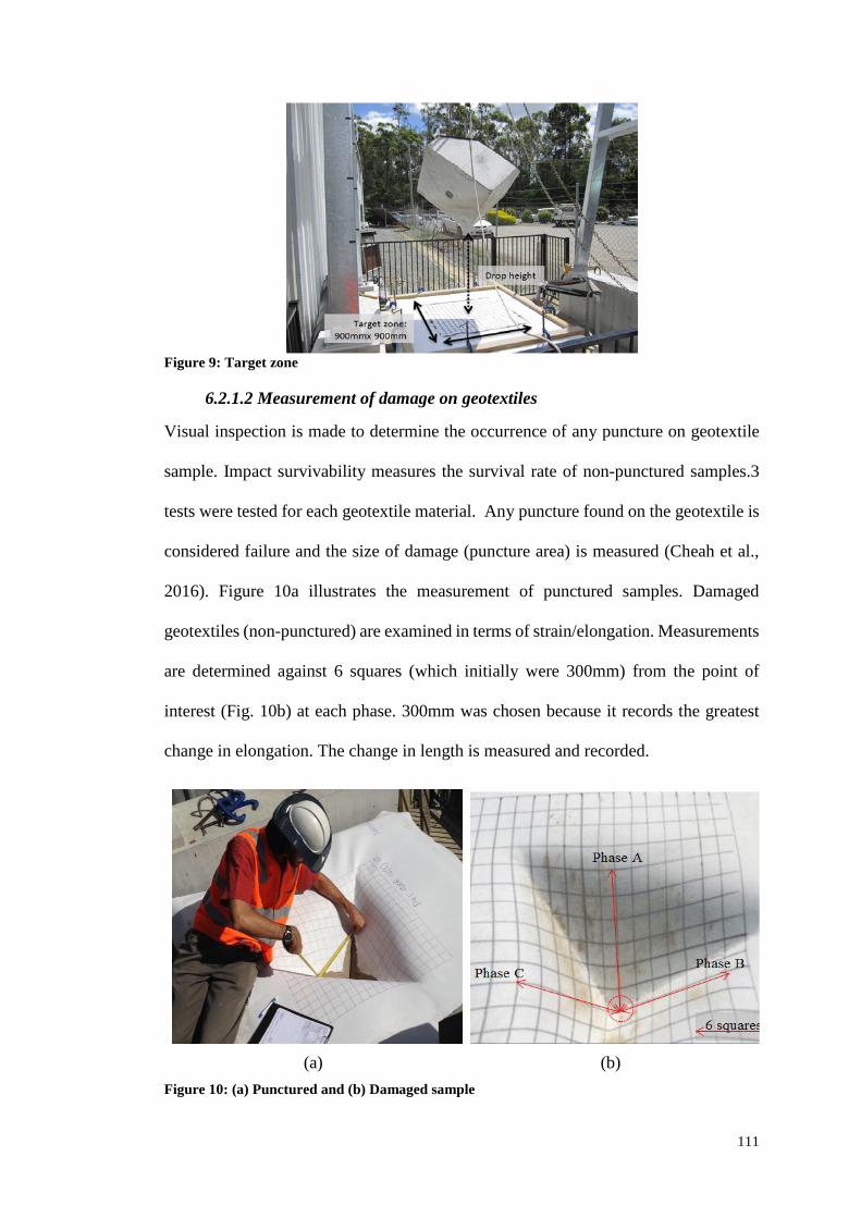
111
Figure 9: Target zone
6.2.1.2 Measurement of damage on geotextiles
Visual inspection is made to determine the occurrence of any puncture on geotextile
sample. Impact survivability measures the survival rate of non-punctured samples.3
tests were tested for each geotextile material. Any puncture found on the geotextile is
considered failure and the size of damage (puncture area) is measured (Cheah et al.,
2016). Figure 10a illustrates the measurement of punctured samples. Damaged
geotextiles (non-punctured) are examined in terms of strain/elongation. Measurements
are determined against 6 squares (which initially were 300mm) from the point of
interest (Fig. 10b) at each phase. 300mm was chosen because it records the greatest
change in elongation. The change in length is measured and recorded.
(a)
(b)
Figure 10: (a) Punctured and (b) Damaged sample
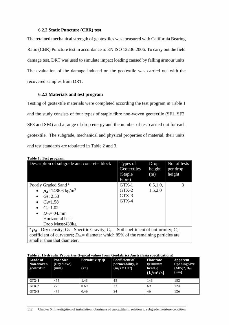
112 Chapter 6: Investigation of installation robustness of geotextiles in relation to subgrade moisture condition
6.2.2 Static Puncture (CBR) test
The retained mechanical strength of geotextiles was measured with California Bearing
Ratio (CBR) Puncture test in accordance to EN ISO 12236:2006. To carry out the field
damage test, DRT was used to simulate impact loading caused by falling armour units.
The evaluation of the damage induced on the geotextile was carried out with the
recovered samples from DRT.
6.2.3 Materials and test program
Testing of geotextile materials were completed according the test program in Table 1
and the study consists of four types of staple fibre non-woven geotextile (SF1, SF2,
SF3 and SF4) and a range of drop energy and the number of test carried out for each
geotextile. The subgrade, mechanical and physical properties of material, their units,
and test standards are tabulated in Table 2 and 3.
Table 1: Test program Description of subgrade and concrete block Types of
Geotextiles (Staple Fibre)
Drop height (m)
No. of tests per drop height
Poorly Graded Sand a
• 𝝆𝝆𝒅𝒅: 1486.6 kg/m3 • Gs: 2.53 • Cu=1.58 • Cc=1.02 • D85= 04.mm
Horizontal base Drop Mass:438kg
GTX-1 GTX-2 GTX-3 GTX-4
0.5,1.0,1.5,2.0
3
a 𝝆𝝆𝒅𝒅= Dry density; Gs= Specific Gravity; Cu= Soil coefficient of uniformity; Cc= coefficient of curvature; D85= diameter which 85% of the remaining particles are smaller than that diameter.
Table 2: Hydraulic Properties (typical values from Geofabrics Australasia specifications) Grade of Non-woven geotextile
Pore Size (Dry Sieve) (mm)
Permittivity, ψ (s-1)
Coefficient of permeability, k (m/s x 10-4)
Flow rate @100mm head, q (L/m2/s)
Apparent Opening Size (AOS)*, O95
(µm)
GTX-1 <75 1.43 45 143 182 GTX-2 <75 0.69 33 69 124 GTX-3 <75 0.46 24 46 126
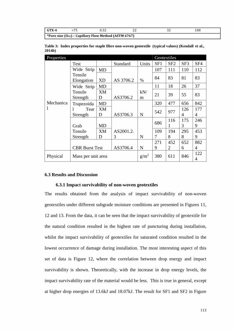
113
GTX-4 <75 0.32 22 32 108 *Pore size (O95) – Capillary Flow Method (ASTM 6767)
Table 3: Index properties for staple fibre non-woven geotextile (typical values) (Kendall et al., 2014b)
6.3 Results and Discussion
6.3.1 Impact survivability of non-woven geotextiles
The results obtained from the analysis of impact survivability of non-woven
geotextiles under different subgrade moisture conditions are presented in Figures 11,
12 and 13. From the data, it can be seen that the impact survivability of geotextile for
the natural condition resulted in the highest rate of puncturing during installation,
whilst the impact survivability of geotextiles for saturated condition resulted in the
lowest occurrence of damage during installation. The most interesting aspect of this
set of data is Figure 12, where the correlation between drop energy and impact
survivability is shown. Theoretically, with the increase in drop energy levels, the
impact survivability rate of the material would be less. This is true in general, except
at higher drop energies of 13.6kJ and 18.07kJ. The result for SF1 and SF2 in Figure
Properties Geotextiles
Mechanical
Test Standard Units SF1 SF2 SF3 SF4 Wide Strip Tensile Elongation
MD
AS 3706.2 %
107 111 110 112
XD 84 83 81 83
Wide Strip Tensile Strength
MD
AS3706.2 kN/m
11 18 26 37 XMD 21 39 55 83
Trapezoidal Tear Strength
MD
AS3706.3 N
320 477 656 842 XMD 542 977 126
4 1774
Grab Tensile Strength
MD AS2001.2.3 N
686 1161
1753
2469
XMD
1097
1948
2958
4539
CBR Burst Test AS3706.4 N 2719
4522
6526
8824
Physical Mass per unit area g/m2 380 611 846 1224
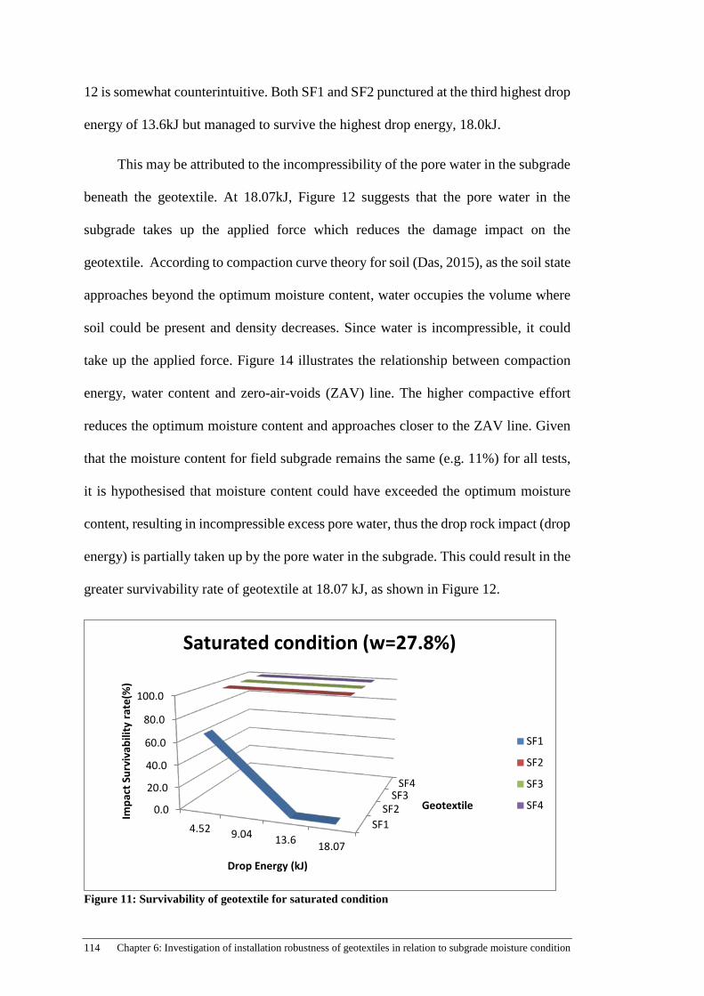
114 Chapter 6: Investigation of installation robustness of geotextiles in relation to subgrade moisture condition
12 is somewhat counterintuitive. Both SF1 and SF2 punctured at the third highest drop
energy of 13.6kJ but managed to survive the highest drop energy, 18.0kJ.
This may be attributed to the incompressibility of the pore water in the subgrade
beneath the geotextile. At 18.07kJ, Figure 12 suggests that the pore water in the
subgrade takes up the applied force which reduces the damage impact on the
geotextile. According to compaction curve theory for soil (Das, 2015), as the soil state
approaches beyond the optimum moisture content, water occupies the volume where
soil could be present and density decreases. Since water is incompressible, it could
take up the applied force. Figure 14 illustrates the relationship between compaction
energy, water content and zero-air-voids (ZAV) line. The higher compactive effort
reduces the optimum moisture content and approaches closer to the ZAV line. Given
that the moisture content for field subgrade remains the same (e.g. 11%) for all tests,
it is hypothesised that moisture content could have exceeded the optimum moisture
content, resulting in incompressible excess pore water, thus the drop rock impact (drop
energy) is partially taken up by the pore water in the subgrade. This could result in the
greater survivability rate of geotextile at 18.07 kJ, as shown in Figure 12.
Figure 11: Survivability of geotextile for saturated condition
SF1SF2
SF3SF4
0.0
20.0
40.0
60.0
80.0
100.0
4.52 9.04 13.6 18.07
Geotextile
Impa
ct S
urvi
vabi
lity
rate
(%)
Drop Energy (kJ)
Saturated condition (w=27.8%)
SF1
SF2
SF3
SF4
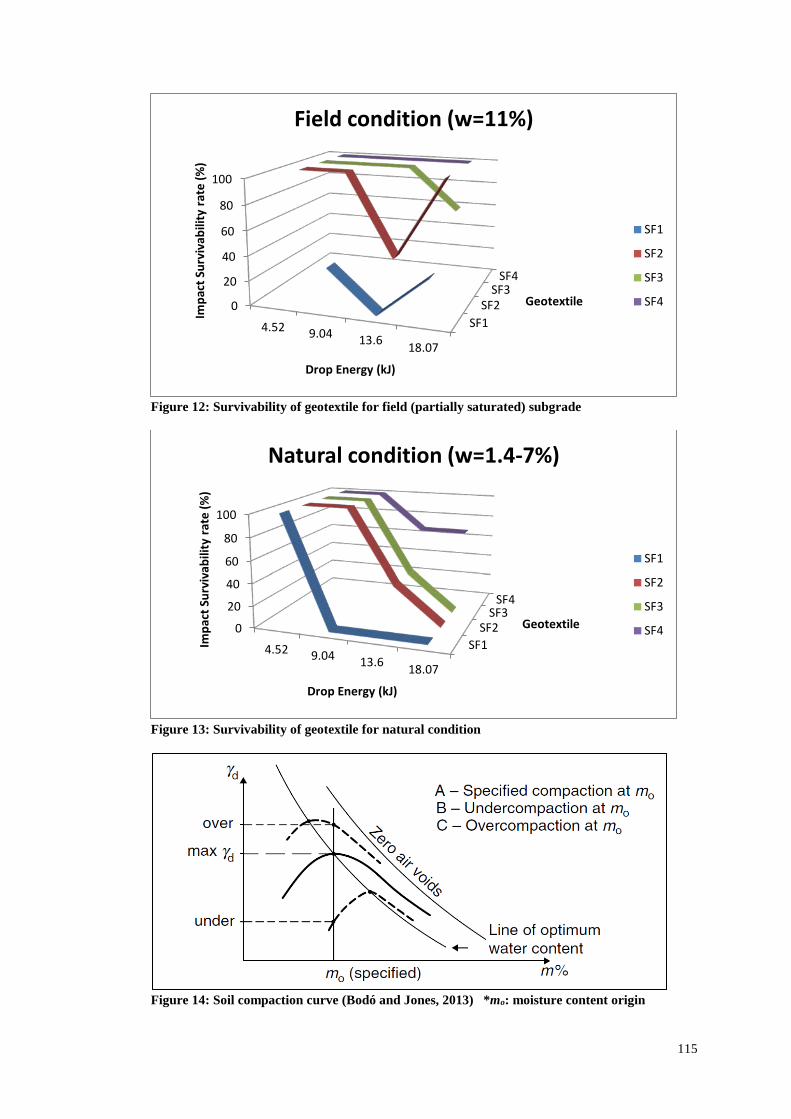
115
Figure 12: Survivability of geotextile for field (partially saturated) subgrade
Figure 13: Survivability of geotextile for natural condition
Figure 14: Soil compaction curve (Bodó and Jones, 2013) *mo: moisture content origin
SF1SF2
SF3SF4
0
20
40
60
80
100
4.52 9.04 13.6 18.07
Geotextile
Impa
ct S
urvi
vabi
lity
rate
(%)
Drop Energy (kJ)
Field condition (w=11%)
SF1
SF2
SF3
SF4
SF1SF2
SF3SF4
0
20
40
60
80
100
4.52 9.04 13.6 18.07
Geotextile
Impa
ct S
urvi
vabi
lity
rate
(%)
Drop Energy (kJ)
Natural condition (w=1.4-7%)
SF1
SF2
SF3
SF4
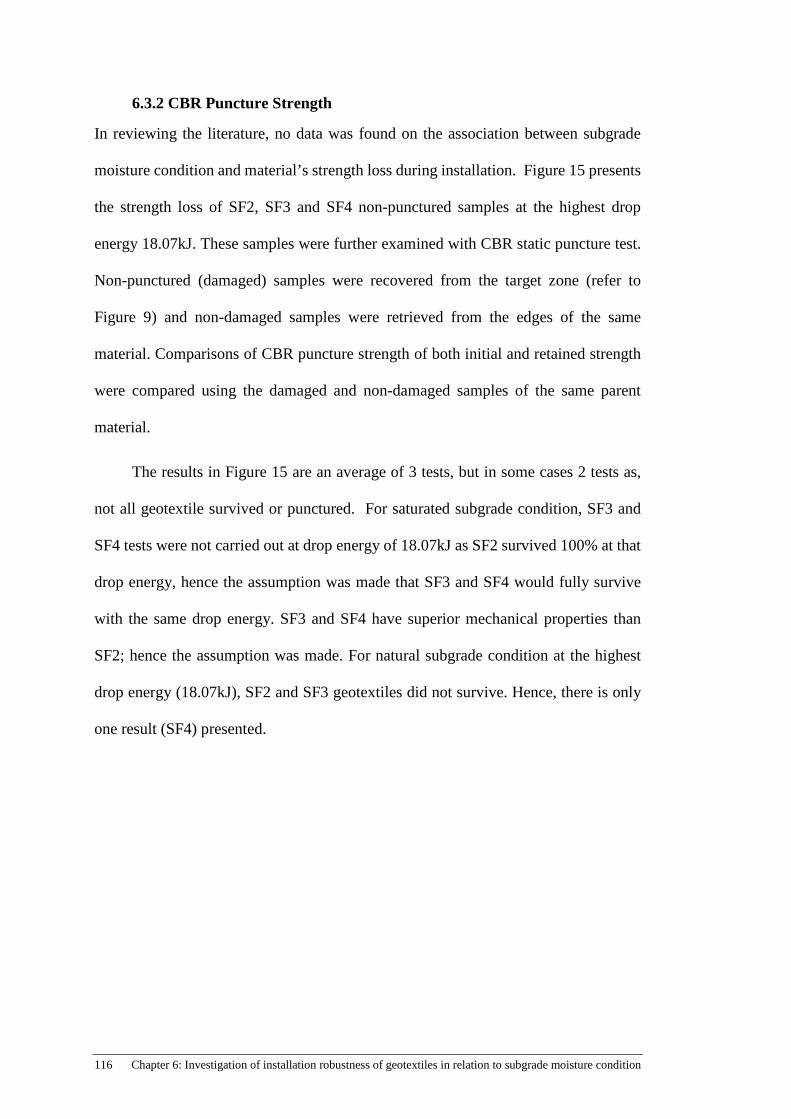
116 Chapter 6: Investigation of installation robustness of geotextiles in relation to subgrade moisture condition
6.3.2 CBR Puncture Strength
In reviewing the literature, no data was found on the association between subgrade
moisture condition and material’s strength loss during installation. Figure 15 presents
the strength loss of SF2, SF3 and SF4 non-punctured samples at the highest drop
energy 18.07kJ. These samples were further examined with CBR static puncture test.
Non-punctured (damaged) samples were recovered from the target zone (refer to
Figure 9) and non-damaged samples were retrieved from the edges of the same
material. Comparisons of CBR puncture strength of both initial and retained strength
were compared using the damaged and non-damaged samples of the same parent
material.
The results in Figure 15 are an average of 3 tests, but in some cases 2 tests as,
not all geotextile survived or punctured. For saturated subgrade condition, SF3 and
SF4 tests were not carried out at drop energy of 18.07kJ as SF2 survived 100% at that
drop energy, hence the assumption was made that SF3 and SF4 would fully survive
with the same drop energy. SF3 and SF4 have superior mechanical properties than
SF2; hence the assumption was made. For natural subgrade condition at the highest
drop energy (18.07kJ), SF2 and SF3 geotextiles did not survive. Hence, there is only
one result (SF4) presented.
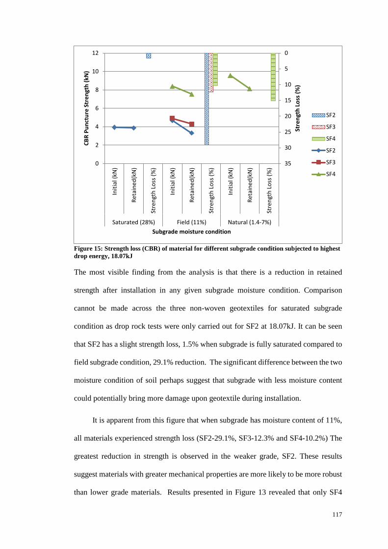
117
Figure 15: Strength loss (CBR) of material for different subgrade condition subjected to highest drop energy, 18.07kJ
The most visible finding from the analysis is that there is a reduction in retained
strength after installation in any given subgrade moisture condition. Comparison
cannot be made across the three non-woven geotextiles for saturated subgrade
condition as drop rock tests were only carried out for SF2 at 18.07kJ. It can be seen
that SF2 has a slight strength loss, 1.5% when subgrade is fully saturated compared to
field subgrade condition, 29.1% reduction. The significant difference between the two
moisture condition of soil perhaps suggest that subgrade with less moisture content
could potentially bring more damage upon geotextile during installation.
It is apparent from this figure that when subgrade has moisture content of 11%,
all materials experienced strength loss (SF2-29.1%, SF3-12.3% and SF4-10.2%) The
greatest reduction in strength is observed in the weaker grade, SF2. These results
suggest materials with greater mechanical properties are more likely to be more robust
than lower grade materials. Results presented in Figure 13 revealed that only SF4
0
5
10
15
20
25
30
350
2
4
6
8
10
12
Initi
al (k
N)
Reta
ined
(kN
)
Stre
ngth
Los
s (%
)
Initi
al (k
N)
Reta
ined
(kN
)
Stre
ngth
Los
s (%
)
Initi
al (k
N)
Reta
ined
(kN
)
Stre
ngth
Los
s (%
)
Saturated (28%) Field (11%) Natural (1.4-7%)
Stre
ngth
Los
s (%
)
CBR
Punc
ture
Str
engt
h (k
N)
Subgrade moisture condition
SF2
SF3
SF4
SF2
SF3
SF4

118 Chapter 6: Investigation of installation robustness of geotextiles in relation to subgrade moisture condition
survived at 18.07kJ under natural sand condition. SF4 showed a similar trend as other
materials with a decrease in retained strength after installation. Though there is only
one set of data for reference, one notable comparison can be made between field and
natural subgrade installation condition; that there is a greater strength reduction (15%)
at natural than at field subgrade condition (10%). Taken together, these results suggest
there is a strong association between subgrade conditions with puncture mechanism
and CBR puncture strength of non-woven geotextiles. It is postulated that the natural
subgrade condition is the harshest environment to install geotextile and will cause
substantial damage.
6.4 Limitations
Several limitations of the DRT approach need to be acknowledged. The intention of
DRT is to simulate the most severe form of damage; the addition of a secondary armour
layer in the DRT system was disregarded due to difficulty replicating. Secondary
armour layer is a common practice for the construction of coastal protection structures,
as it cushions the impact dumped onto the laid geotextile. The tests were carried out
on a horizontal plane, whilst on site; many geotextiles are not always installed in this
way.
6.5 Conclusions
This study set out to investigate the influence of subgrade moisture content on
the puncture mechanism of geotextile filter. These findings suggest that for the same
geotextile and same drop energy, the damage on the geotextile is more severe in the
case of natural subgrade than in the case of saturated subgrade. These data suggest that
moisture content of soil does play a significant role in the robustness of geotextile
during installation. Findings suggest that there is a correlation between pore water and
geotextiles’ robustness. As the compaction of soil approaches beyond the optimum
119
moisture content, resulting in incompressible excess pore water, the drop energy of the
released concrete block could have been partially taken up by the pore water in the
subgrade. This could result in the greater survivability (robustness) rate of geotextile
when higher drop energy (18.07kJ) was applied under field condition (11%). The
extent of damage (mechanical strength reduction) due to moisture content of soil was
further investigated with CBR static puncture test. This research provides a baseline
for the exploration of the influence of subgrade on the robustness of geotextile in
construction of coastal revetment. Findings highlight the use of DRT as an effective
installation assessment tool of geotextile filters for coastal revetment construction. It
is often challenging and difficult to derive meaningful information from samples
retrieved from site due to the lack of information during installation.
Acknowledgements
This study is part of the first author’s PhD research at Queensland University of
Technology (QUT) in Brisbane and therefore authors would like to acknowledge QUT
Australian Postgraduate Award (APA) providing the scholarship to the first author for
her PhD study. The authors express their appreciation to Geofabrics Australasia for
providing the geosynthetics materials and financial support in this study. Finally, the
authors wish to thank undergraduate project students who helped in these testings;
their work is gratefully acknowledged.
References
Abu-Farsakh, M., Coronel, J., Tao, M., 2007. Effect of Soil Moisture Content and Dry Density on Cohesive Soil–Geosynthetic Interactions Using Large Direct Shear Tests. Journal of Materials in Civil Engineering 19, 540-549.
Bodó, B., Jones, C., 2013. Introduction to Soil Mechanics. Wiley-Blackwell, GB. Bräu, G., 1996. Damage of Geosynthetics During Installation- Experience from Real
Sites and Research Works, in: De Groot, M.B., Den Hoedt, G., Termaat, R.J. (Eds.), Proceedings of the First European Geosythetics Conference- Eurogeo 1. Balkema, Maastricht, Netherlands, pp. 145-150.
120 Chapter 6: Investigation of installation robustness of geotextiles in relation to subgrade moisture condition
Carneiro, J.R., Morais, L.M., Moreira, S.P., Lopes, M.L., 2013. Evaluation of the Damages Occurred During the Installation of Non-Woven Geotextiles. Materials Science Forum 730-732, 439-444.
Cheah, C., Gallage, C., Dawes, L., Kendall, P., 2016. Impact resistance and evaluation of retained strength on geotextiles. Geotextiles and Geomembranes 44, 549-556.
Chew, S.H., Karunaratne, G.P., Tan, S.A., Wong, W.K., 1999. Standardized Drop Test (SDT) to evaluate puncture resistance of geotextiles in coastal revetments, Rencontres Geosynthetics 99, Bordeaux, France, pp. 303-310.
Das, B.M., 2015. Principles of foundation engineering: SI edition. Cengage Learning, Boston.
Elvidge, C.B., Raymond, G.P., 1999. Laboratory survivability of nonwoven geotextiles on open-graded crushed aggregate. Geosynthetics International 6, 93-117.
European Standard Online, 2006. EN ISO 12236 Geosynthetics-Static Puncture Test (CBR Puncture Test).
Heibaum, M., 2014. Geosynthetics for waterways and flood protection structures – Controlling the interaction of water and soil. Geotextiles and Geomembranes 42, 374-393.
Heibaum, M., 2016. Geotextiles used in filtration, Geotextiles- From Design to Applications. Elsevier, p. 257.
Kendall , P., Austin, R.A., Cheah , C., Lacey , M., 2014b. Large Scale Controlled Testing of Geotextile Puncture Resistance for Rock Impact, 10th International Conference on Geosynthetics. Deutsche Gesellschaft für Geotechnik e.V., Berlin Germany.
Lopes, P.C., Lopes, M.L., Lopes, M.P., 2001. Shear Behaviour of Geosynthetics in the Inclined Plane Test – Influence of Soil Particle Size and Geosynthetic Structure, Geosynthetics International, pp. 327-342.
Rosete, A., Lopes, P.M., Pinho-Lopes, M., Lopes, M.L., 2013. Tensile and hydraulic properties of geosynthetics after mechanical damage and abrasion laboratory tests. Geosynthetics International 20, 358-374.
Tessilbrenta, 2013. Coastal Erosion Prevention. Tessilbrenta S.r.l. Watn, A., Chew, S., 2002. Geosynthetic damage-from laboratory to field,
Geosynthetics: State of the Art- Recent Developments. Proceedings of the Seventh International Conference of Geosynthetics,7 ICG held 22-27 September 2002, Nice, France. Volume 4.
Wong, W.K., Chew, S.H., Karunaratne, G.P., Tan, S.A., Yee, K.Y., 2000. Evaluating the puncture survivability of geotextiles in construction of coastal revetments, Sessions of Geo-Denver 2000 - Advances in Transportation and Geoenvironmental Systems Using Geosynthetics, GSP 103, August 5, 2000 - August 8, 2000. American Society of Civil Engineers, Denver, CO, United states, pp. 186-200.
121
Chapter 7: Discussion
7.1 Introduction
The overall aim of the research has been achieved through the ongoing development
of an experimental method to replicate construction stress called the Drop Rock Test
(DRT). The influence of construction stresses (rock dumping) on geotextiles’
robustness, mechanical and filtration properties were investigated with the newly
developed DRT methodology. The influence of subgrade moisture condition on
geotextile’s robustness was also achieved using DRT.
The following research objectives have been attained:
1. Developed new experimental method to replicate construction stress (rock
dumping) on geotextiles for coastal application
2. Examined the influence of construction stress on geotextiles properties
(robustness, mechanical strength, physical and filtration)
3. Examined the influence of subgrade characteristics (i.e. moisture condition) on
geotextiles’ robustness during installation
4. Developed design chart to predict robustness of geotextile during installation
5. Developed design chart to predict the hydraulic/ filtration performance
(permittivity) after installation
6. Developed chart for robustness of geotextile against subgrade moisture
condition
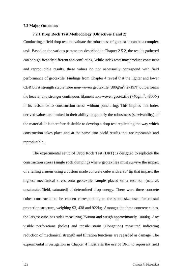
122 Chapter 7: Discussion
7.2 Major Outcomes
7.2.1 Drop Rock Test Methodology (Objectives 1 and 2)
Conducting a field drop test to evaluate the robustness of geotextile can be a complex
task. Based on the various parameters described in Chapter 2.5.2, the results gathered
can be significantly different and conflicting. While index tests may produce consistent
and reproducible results, these values do not necessarily correspond with field
performance of geotextile. Findings from Chapter 4 reveal that the lighter and lower
CBR burst strength staple fibre non-woven geotextile (380g/m2, 2719N) outperforms
the heavier and stronger continuous filament non-woven geotextile (740g/m2, 4800N)
in its resistance to construction stress without puncturing. This implies that index
derived values are limited in their ability to quantify the robustness (survivability) of
the material. It is therefore desirable to develop a drop test replicating the way which
construction takes place and at the same time yield results that are repeatable and
reproducible.
The experimental setup of Drop Rock Test (DRT) is designed to replicate the
construction stress (single rock dumping) where geotextiles must survive the impact
of a falling armour using a custom made concrete cube with a 90o tip that imparts the
highest mechanical stress onto geotextile sample placed on a test soil (natural,
unsaturated/field, saturated) at determined drop energy. There were three concrete
cubes constructed to be chosen corresponding to the stone size used for coastal
protection structure, weighing 93, 438 and 922kg. Amongst the three concrete cubes,
the largest cube has sides measuring 750mm and weigh approximately 1000kg. Any
visible perforations (holes) and tensile strain (elongation) measured indicating
reduction of mechanical strength and filtration functions are regarded as damage. The
experimental investigation in Chapter 4 illustrates the use of DRT to represent field

123
conditions and controlling a wide a range of experimental variables (mass and
angularity of concrete, subgrade characteristics and drop height). Induced damage on
geotextiles from DRT is examined with the Static Puncture test and data recorded is
used to develop a geotextile selection design chart for coastal protection applications.
Several limitations of the DRT approach need to be acknowledged. First, the test
is carried out on a horizontal plane, whilst on-site; geotextiles could be installed on
various inclinations. Second, results gathered with a single mass rock, whereas bulk
loads of armour rocks are often dropped on geotextile during installation. Third, this
study was limited by the absence of a secondary armour layer which are applied on
geotextiles to cushion the impact dumped on the geotextiles.
7.2.2 Geotextiles’ robustness against construction stress (rock dumping) (Objective 4)
The important outcome of Chapter 4 is the development of preliminary design chart of
geotextiles’ robustness against construction stress. This chart aids engineers and
designers in selecting the appropriate product and will minimise the risk of puncture
in their application. Figure 7-1 presents the relationship between survivability
(puncture/no puncture) of staple fibre non-woven geotextiles, drop energy and CBR
deformation energy. Survivability (robustness) of geotextile refers to the number of
samples that survived (no puncture) for a series of drop rock tests. The term drop
energy is derived from potential energy,
𝐸𝐸𝑑𝑑𝑑𝑑𝑔𝑔𝑑𝑑 = 𝑚𝑚𝑚𝑚ℎ
Where m is the mass of the concrete block (armour unit), g is the gravitational
acceleration and h represents the installation height. Drop energy conveniently
summarizes the relevant installation specifications such as rock size and drop height.
Thus, drop energy is selected to represent the results. CBR energy refers to the area
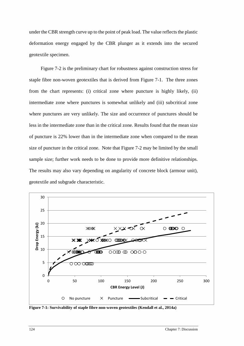
124 Chapter 7: Discussion
under the CBR strength curve up to the point of peak load. The value reflects the plastic
deformation energy engaged by the CBR plunger as it extends into the secured
geotextile specimen.
Figure 7-2 is the preliminary chart for robustness against construction stress for
staple fibre non-woven geotextiles that is derived from Figure 7-1. The three zones
from the chart represents: (i) critical zone where puncture is highly likely, (ii)
intermediate zone where punctures is somewhat unlikely and (iii) subcritical zone
where punctures are very unlikely. The size and occurrence of punctures should be
less in the intermediate zone than in the critical zone. Results found that the mean size
of puncture is 22% lower than in the intermediate zone when compared to the mean
size of puncture in the critical zone. Note that Figure 7-2 may be limited by the small
sample size; further work needs to be done to provide more definitive relationships.
The results may also vary depending on angularity of concrete block (armour unit),
geotextile and subgrade characteristic.
Figure 7-1: Survivability of staple fibre non-woven geotextiles (Kendall et al., 2014a)
0
5
10
15
20
25
30
0 50 100 150 200 250 300
Drop
Ene
rgy
(kJ)
CBR Energy Level (J)
No puncture Puncture Subcritical Critical
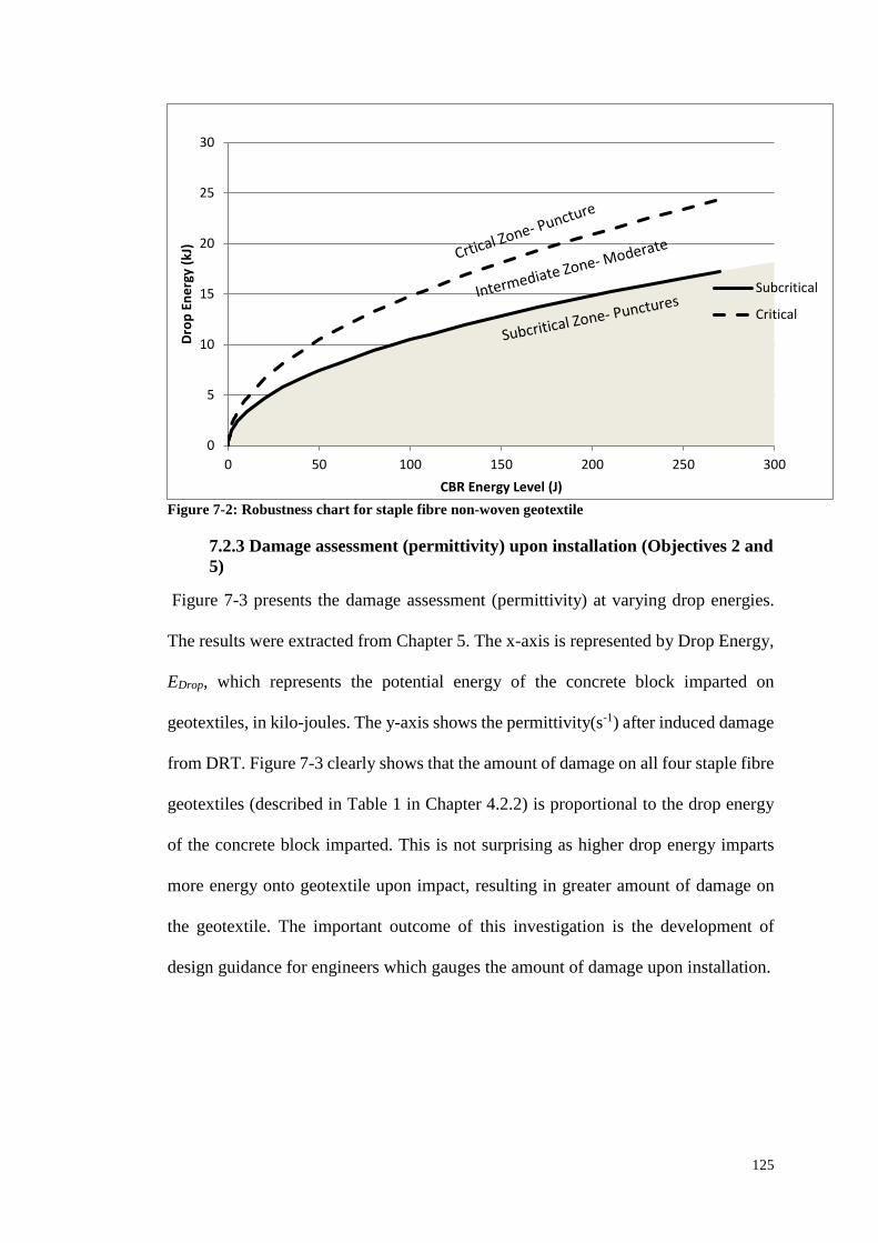
125
Figure 7-2: Robustness chart for staple fibre non-woven geotextile
7.2.3 Damage assessment (permittivity) upon installation (Objectives 2 and 5)
Figure 7-3 presents the damage assessment (permittivity) at varying drop energies.
The results were extracted from Chapter 5. The x-axis is represented by Drop Energy,
EDrop, which represents the potential energy of the concrete block imparted on
geotextiles, in kilo-joules. The y-axis shows the permittivity(s-1) after induced damage
from DRT. Figure 7-3 clearly shows that the amount of damage on all four staple fibre
geotextiles (described in Table 1 in Chapter 4.2.2) is proportional to the drop energy
of the concrete block imparted. This is not surprising as higher drop energy imparts
more energy onto geotextile upon impact, resulting in greater amount of damage on
the geotextile. The important outcome of this investigation is the development of
design guidance for engineers which gauges the amount of damage upon installation.
0
5
10
15
20
25
30
0 50 100 150 200 250 300
Drop
Ene
rgy
(kJ)
CBR Energy Level (J)
Subcritical
Critical
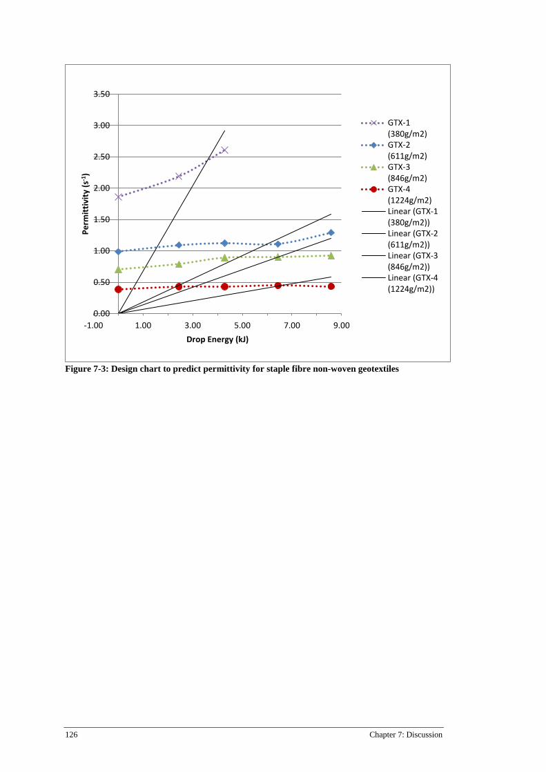
126 Chapter 7: Discussion
Figure 7-3: Design chart to predict permittivity for staple fibre non-woven geotextiles
0.00
0.50
1.00
1.50
2.00
2.50
3.00
3.50
-1.00 1.00 3.00 5.00 7.00 9.00
Perm
ittiv
ity (s
-1)
Drop Energy (kJ)
GTX-1(380g/m2)GTX-2(611g/m2)GTX-3(846g/m2)GTX-4(1224g/m2)Linear (GTX-1(380g/m2))Linear (GTX-2(611g/m2))Linear (GTX-3(846g/m2))Linear (GTX-4(1224g/m2))
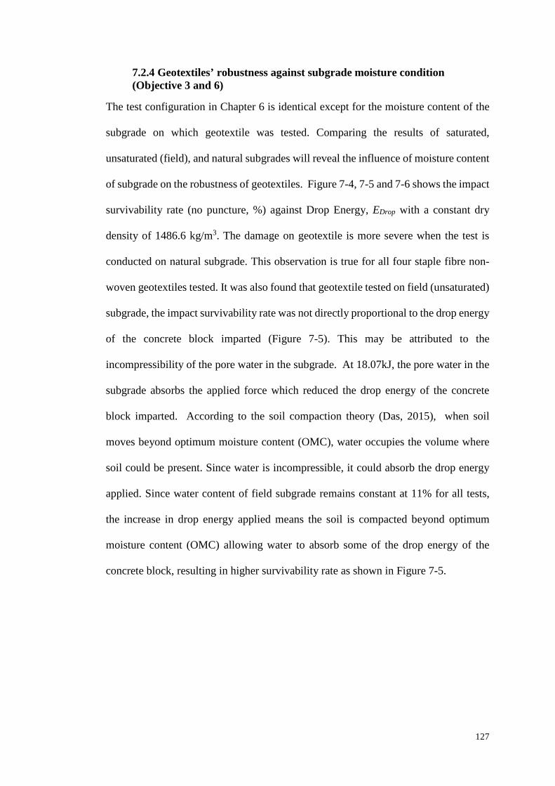
127
7.2.4 Geotextiles’ robustness against subgrade moisture condition (Objective 3 and 6)
The test configuration in Chapter 6 is identical except for the moisture content of the
subgrade on which geotextile was tested. Comparing the results of saturated,
unsaturated (field), and natural subgrades will reveal the influence of moisture content
of subgrade on the robustness of geotextiles. Figure 7-4, 7-5 and 7-6 shows the impact
survivability rate (no puncture, %) against Drop Energy, EDrop with a constant dry
density of 1486.6 kg/m3. The damage on geotextile is more severe when the test is
conducted on natural subgrade. This observation is true for all four staple fibre non-
woven geotextiles tested. It was also found that geotextile tested on field (unsaturated)
subgrade, the impact survivability rate was not directly proportional to the drop energy
of the concrete block imparted (Figure 7-5). This may be attributed to the
incompressibility of the pore water in the subgrade. At 18.07kJ, the pore water in the
subgrade absorbs the applied force which reduced the drop energy of the concrete
block imparted. According to the soil compaction theory (Das, 2015), when soil
moves beyond optimum moisture content (OMC), water occupies the volume where
soil could be present. Since water is incompressible, it could absorb the drop energy
applied. Since water content of field subgrade remains constant at 11% for all tests,
the increase in drop energy applied means the soil is compacted beyond optimum
moisture content (OMC) allowing water to absorb some of the drop energy of the
concrete block, resulting in higher survivability rate as shown in Figure 7-5.
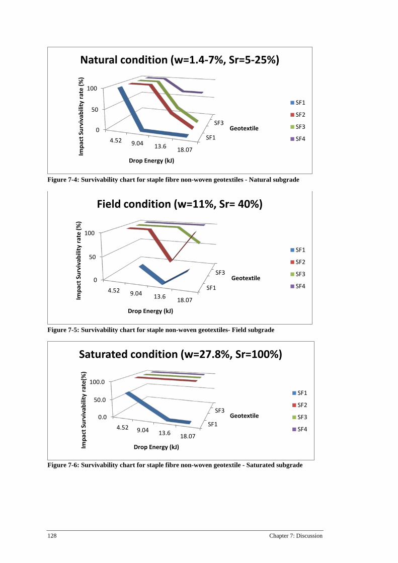
128 Chapter 7: Discussion
Figure 7-4: Survivability chart for staple fibre non-woven geotextiles - Natural subgrade
Figure 7-5: Survivability chart for staple non-woven geotextiles- Field subgrade
Figure 7-6: Survivability chart for staple fibre non-woven geotextile - Saturated subgrade
SF1
SF30
50
100
4.52 9.04 13.6 18.07
Geotextile
Impa
ct S
urvi
vabi
lity
rate
(%)
Drop Energy (kJ)
Natural condition (w=1.4-7%, Sr=5-25%)
SF1
SF2
SF3
SF4
SF1
SF30
50
100
4.52 9.04 13.6 18.07
Geotextile
Impa
ct S
urvi
vabi
lity
rate
(%)
Drop Energy (kJ)
Field condition (w=11%, Sr= 40%)
SF1
SF2
SF3
SF4
SF1
SF30.0
50.0
100.0
4.52 9.04 13.6 18.07
Geotextile
Impa
ct S
urvi
vabi
lity
rate
(%)
Drop Energy (kJ)
Saturated condition (w=27.8%, Sr=100%)
SF1
SF2
SF3
SF4
129
7.2.5 Research Impact for other forms of geosynthetics
The methodology to simulate construction stress for coastal applications can be
extended for other geotextile elements such as geotextile bags, geotextile containers,
geotextile mattress as well geotextile tubes. One disadvantage of designing coastal
protection structure with theses geotextile elements is that they are susceptible to
damage during installation. These damages often occur due to poor installation
practice such as rock dumping upon geotextile. These geotextile elements can be used
in combination with armour rocks. The functional requirements of these geotextile
elements can be examined with the Drop Rock Test (DRT).
Non-woven geotextiles are often used as a drainage and protection layer for
geomembranes or geotextile elements (bag/containers/mattress/tube) against sharp
objects like rip raps or gravel in either the soil/rock layer above or below. Non-woven
geotextiles are generally manufactured with Polyester (PET) and Polypropylene (PP).
Up to this date, little focus is given on the different combination percentage of PET
and PP against puncture resistance. The DRT could also be used as a tool to optimise
manufacturing process of non-woven geotextile. Using different composition of
material (PET and PP) and DRT results, manufacturers can optimise both cost and
quality.
130 Chapter 8: Conclusion
Chapter 8: Conclusion
8.1 Conclusions
Past research points out that the heavy construction stresses imparted onto geotextile
material in coastal protection applications usually exceeds the service stresses. This
suggests that the critical period for geotextiles is during the installation/ construction
process. Therefore, it is essential to assess and estimate any change in mechanical and
filtration properties of geotextiles upon installation where construction stress
(dropping rocks) is involved. The damages inflicted on geotextiles during construction
and failure to consider the extent of damage upon installation in the design process can
hinder the long-term performance of geotextiles. Typically, these issues are related to
the inadequate method of selecting geotextiles and the lack of experimental methods
to replicate installation conditions in repeatable and controlled manner. To select the
appropriate geotextiles, more scientifically robust methods of assessing geotextiles
robustness and their mechanical and filtration properties upon installation is essential.
The focus of this research project was to develop a methodology to replicate the
installation condition and to assess the robustness of geotextiles under coastal
protection application. Both construction stress and subgrade characteristics factors
were integrated to examine the robustness of geotextile upon installation. The
developed method, Drop Rock Test was used to induce similar on-site construction
stresses on geotextiles to assess the influence of rock dumping on the retained strength
and filtration properties of geotextiles. The research objectives have been achieved as
demonstrated below:
1. Developed new experimental method to replicate construction stress (rock
dumping) on geotextiles for coastal application- The Drop Rock Test was
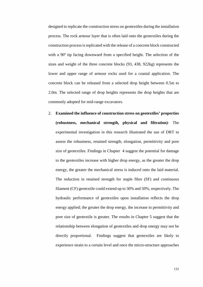
131
designed to replicate the construction stress on geotextiles during the installation
process. The rock armour layer that is often laid onto the geotextiles during the
construction process is replicated with the release of a concrete block constructed
with a 90o tip facing downward from a specified height. The selection of the
sizes and weight of the three concrete blocks (93, 438, 922kg) represents the
lower and upper range of armour rocks used for a coastal application. The
concrete block can be released from a selected drop height between 0.5m to
2.0m. The selected range of drop heights represents the drop heights that are
commonly adopted for mid-range excavators.
2. Examined the influence of construction stress on geotextiles’ properties
(robustness, mechanical strength, physical and filtration)- The
experimental investigation in this research illustrated the use of DRT to
assess the robustness, retained strength, elongation, permittivity and pore
size of geotextiles. Findings in Chapter 4 suggest the potential for damage
to the geotextiles increase with higher drop energy, as the greater the drop
energy, the greater the mechanical stress is induced onto the laid material.
The reduction in retained strength for staple fibre (SF) and continuous
filament (CF) geotextile could extend up to 30% and 50%, respectively. The
hydraulic performance of geotextiles upon installation reflects the drop
energy applied; the greater the drop energy, the increase in permittivity and
pore size of geotextile is greater. The results in Chapter 5 suggest that the
relationship between elongation of geotextiles and drop energy may not be
directly proportional. Findings suggest that geotextiles are likely to
experience strain to a certain level and once the micro-structure approaches

132 Chapter 8: Conclusion
breaking point, the material ceased to elongate further and is on the verge of
puncturing.
3. Examined the influence of subgrade characteristics (i.e. moisture
condition) on geotextiles’ robustness during installation- Chapter 6
investigated the robustness of geotextiles against different subgrade
moisture conditions. The findings suggest that for the same geotextile and
same drop energy, the damage on geotextiles is more severe in the case of
natural subgrade than in the case of saturated subgrade. Chapter 6 provided
a baseline for the exploration of the influence of subgrade moisture
condition on the robustness of geotextile in construction of coastal
revetment. It is also hypothesised that as the compaction of soil approaches
beyond the optimum moisture content, resulting in incompressible excess
pore water, the drop energy of the released concrete block could have been
partially taken up by the pore water in the subgrade. This could result in the
greater survivability (robustness) rate of geotextile when higher drop energy
(18.07kJ) was applied under field conditions.
4. Developed design chart to predict robustness of geotextile during
installation- The robustness chart developed in Chapter 7.2.2_Figure 7-2
allows engineers and designers to select the appropriate staple fibre non-
woven geotextile to minimise the risk of damage during installation process
using drop energy (function of drop height and weight of armour stone) and
CBR energy of geotextiles. This presents a cost effective method as it would
not require large scale field trials, which are often costly and time-
consuming.
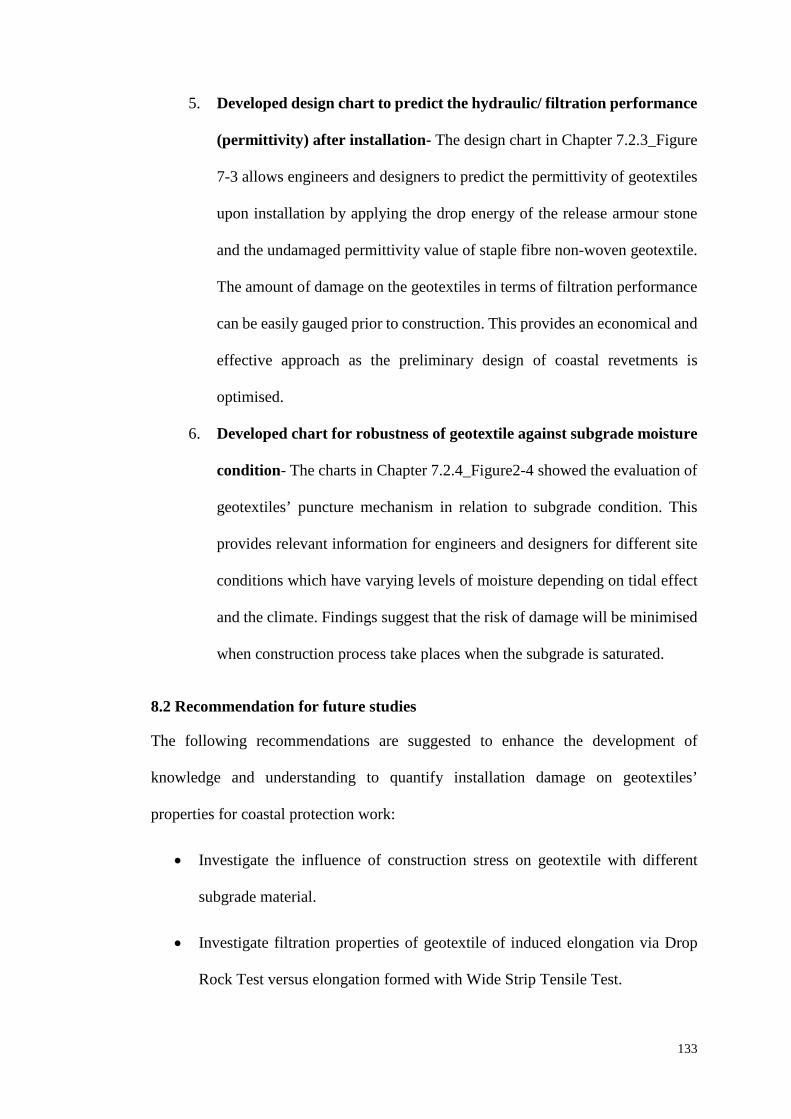
133
5. Developed design chart to predict the hydraulic/ filtration performance
(permittivity) after installation- The design chart in Chapter 7.2.3_Figure
7-3 allows engineers and designers to predict the permittivity of geotextiles
upon installation by applying the drop energy of the release armour stone
and the undamaged permittivity value of staple fibre non-woven geotextile.
The amount of damage on the geotextiles in terms of filtration performance
can be easily gauged prior to construction. This provides an economical and
effective approach as the preliminary design of coastal revetments is
optimised.
6. Developed chart for robustness of geotextile against subgrade moisture
condition- The charts in Chapter 7.2.4_Figure2-4 showed the evaluation of
geotextiles’ puncture mechanism in relation to subgrade condition. This
provides relevant information for engineers and designers for different site
conditions which have varying levels of moisture depending on tidal effect
and the climate. Findings suggest that the risk of damage will be minimised
when construction process take places when the subgrade is saturated.
8.2 Recommendation for future studies
The following recommendations are suggested to enhance the development of
knowledge and understanding to quantify installation damage on geotextiles’
properties for coastal protection work:
• Investigate the influence of construction stress on geotextile with different
subgrade material.
• Investigate filtration properties of geotextile of induced elongation via Drop
Rock Test versus elongation formed with Wide Strip Tensile Test.
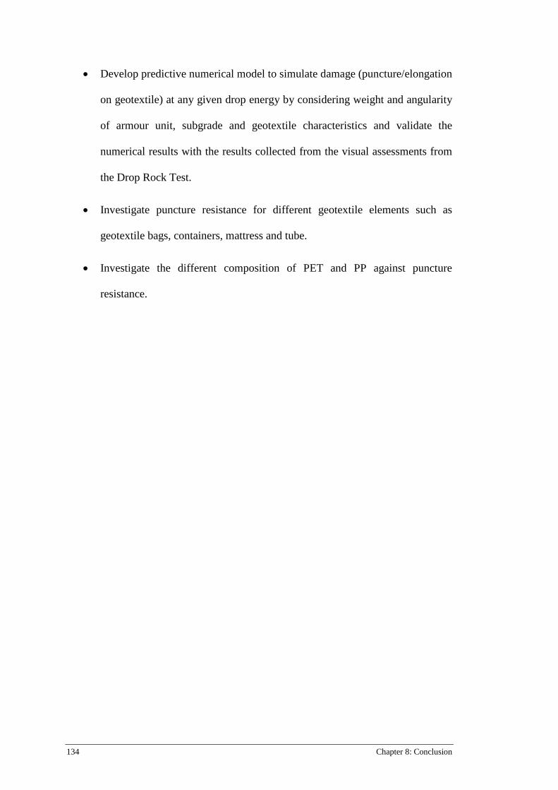
134 Chapter 8: Conclusion
• Develop predictive numerical model to simulate damage (puncture/elongation
on geotextile) at any given drop energy by considering weight and angularity
of armour unit, subgrade and geotextile characteristics and validate the
numerical results with the results collected from the visual assessments from
the Drop Rock Test.
• Investigate puncture resistance for different geotextile elements such as
geotextile bags, containers, mattress and tube.
• Investigate the different composition of PET and PP against puncture
resistance.
Bibliography 135
Bibliography
AS 2001.2.3.2- 2001 Methods of test for textiles-Physical tests- Determination of maximum force using the grab method (ISO 13934-2:1999, MOD).
AS 3706.1-2012 Geotextiles- Methods of test- General requirements, sampling, conditioning, basic physical properties and statistical analysis.
AS 3706.2-2012 Geotextiles-Methods of Test-Determination of tensile properties- Wide strip and grab method.
AS 3706.3-2012 Geotextiles- Methods of Test- Determination of tearing strength- Trapezoidal method.
AS 3706.4-2012 Geotextiles- Methods of test- Determination of burst strength- California Bearing ratio (CBR) Plunger method.
AS 3706.5-2014 Geotextiles - Method of Test: Determination of puncture resistance- Drop cone method.
ASTM D4751-2016 Standard Test Methods for Determining Apparent Opening Size of a Geoxtextile.
Abromeit, H., Heibaum, M., 1996. Stressing of geosynthetics during installation and construction on site: Installation of geosynthetics in waterways, Proceedings of the First European Geosynthetics Conference EuroGeo.
Abu-Farsakh, M., Coronel, J., Tao, M., 2007. Effect of Soil Moisture Content and Dry Density on Cohesive Soil–Geosynthetic Interactions Using Large Direct Shear Tests. Journal of Materials in Civil Engineering 19, 540-549.
Ameraunga, J., Boyle, P.J., Loke, K.H., Hornsey, W., Stevens, M., 2006. Use of geotextiles to overcome challenging conditions at the seawall project in Port of Brisbane, 8th International Conference on Geosynthetics, Yokohama, Japan.
Berendsen, E., 1996. Dumping of rock on geotextiles. Geosynthetics: applications, design and construction. Proc. 1st European geosynthetics conference, Maastricht, 1996, 919-924.
Bhatia, S.K., Smith, J.L., 1996. Geotextile Characterization and Pore Size Distribution: Part I A Review of Manufacturing Process. Geosynthetics International 3, 85-105.
Bodó, B., Jones, C., 2013. Introduction to Soil Mechanics. Wiley-Blackwell, GB. Bräu, G., 1996. Damage of Geosynthetics During Installation- Experience from Real
Sites and Research Works, in: De Groot, M.B., Den Hoedt, G., Termaat, R.J. (Eds.), Proceedings of the First European Geosythetics Conference- Eurogeo 1. Balkema, Maastricht, Netherlands, pp. 145-150.
Briaud, J.-L., 2013. Geosynthetics, Geotechnical Engineering. John Wiley & Sons, Inc., pp. 904-937.
BSI, 1998a. EN ISO 13427 (1998) Geotextiles and Geotextile-related Products. Abrasion Damage Simulation (sliding block test), London, UK.
BSI, 1998b. ENV ISO 10722-1 (1998) Geotextiles and Geotextile-related products - Procedure for Simulating Damage During Installation - Part 1: Installation in Granular Materials, London, UK.
BSI, 2007. EN ISO 10722 (2007) Geosynthetics, Index Test Procedure for the Evaluation of Mechanical Damage under Repeated Loading - Damage caused by Granular Material, London, UK.
Carneiro, J.R., Morais, L.M., Moreira, S.P., Lopes, M.L., 2013. Evaluation of the Damages Occurred During the Installation of Non-Woven Geotextiles. Materials Science Forum 730-732, 439-444.
136 Bibliography
Cheah, C., Gallage, C., Dawes, L., Kendall, P., 2015. Effect of Simulated Rock Dumping on Geotextile, 12th Australia New Zealand Conference on Geomechanics, Wellington, New Zealand.
Cheah, C., Gallage, C., Dawes, L., Kendall, P., 2016. Impact resistance and evaluation of retained strength on geotextiles. Geotextiles and Geomembranes 44, 549-556.
Cheah, C., Gallage, C., Dawes, L., Kendall, P., 2017. Measuring hydraulic properties of geotextiles after installation damage. Geotextiles and Geomembranes 45, 462-470.
Chew, S.H., Karunaratne, G.P., Tan, S.A., Wong, W.K., 1999. Standardized Drop Test (SDT) to evaluate puncture resistance of geotextiles in coastal revetments, Rencontres Geosynthetics 99, Bordeaux, France, pp. 303-310.
Christopher, B., Elias, V., 1998. Evaluation of installation damage in geosynthetics: a US perspective, Seminar volume on Installation Damage in Geosynthetics, p. 1.2.
Christopher, B.R., 1983. Evaluation of two geotextile installation in excess of a decade old. Transportation Research Record, 79-88.
Christopher, B.R., Fischer, G.R., 1992. Geotextile filtration principles, practices and problems. Geotextiles and Geomembranes 11, 337-353.
Das, B.M., 2015. Principles of foundation engineering: SI edition. Cengage Learning, Boston.
Diederich, R., 2000. Evaluation of Installation Damage of Geotextiles. A Correlation to Index Tests. Fifth conferece on Geosynthetics, YiChang, China, 24-31.
Elvidge, C.B., Raymond, G.P., 1999. Laboratory survivability of nonwoven geotextiles on open-graded crushed aggregate. Geosynthetics International 6, 93-117.
European Standard Online, 2006. EN ISO 12236 Geosynthetics-Static Puncture Test (CBR Puncture Test).
Giroud, J.P., 1984. Geotextiles and geomembranes. Geotextiles and Geomembranes 1, 5-40.
Giroud, J.P., 2000. Lessons Learned From Failures and Sucessess Associated with Geosynthetics, Second European Conference on Geosynthetics. Proceedings of Eurogeo 2, Bologna, Italy, pp. 77-118.
Giroud, J.P., 2005. Geosynthetics Engineering: Sucessess, Failures, and Lesson Learned. The Vienna Terzaghi Lecture, 5 Osterreichische Geotechnikagung, Vienna, Austria.
Heerten, G., 1980. Long-term experience with the use of synthetic filter fabrics in coastal engineering. Coastal Engineering Proceedings 1.
Heerten, G., 1984. Geotextiles in coastal engineering—25 years experience. Geotextiles and Geomembranes 1, 119-141.
Heerten, G., 2007. Revetment Design- Lessons learnt from failures, 10th Australia New Zealand Conference on Geomechanics. Australian Geomechanics Society, Brisbane, pp. 324-329.
Heerten, G., 2008. Needle-punched nonwoven GTX in coastal engineering applications, Chinese-German Joint Symposium on Hydraulic and Ocean Engineering, Darmstadt, Germany.
Heibaum, M., 2014. Geosynthetics for waterways and flood protection structures – Controlling the interaction of water and soil. Geotextiles and Geomembranes 42, 374-393.
Bibliography 137
Heibaum, M., 2016. Geotextiles used in filtration, Geotextiles- From Design to Applications. Elsevier, p. 257.
Holtz, R.D., Christopher, B.R., Berg, R.R., 1997. Geosythetic Engineering. BiTech Publishers Ltd., Richmond, British Columbia, Canada.
Hornsey, W.P., 2012. Geotextiles in specialise marine applications: an australia prespective over 32 years. Geofabrics Australasia.
Hsuan, Y., Schroeder, H., Rowe, K., Müller, W., Greenwood, J., Cazzuffi, D., Koerner, R., 2008. Long-term performance and lifetime prediction of geosynthetics, Proceeding of EuroGeo 4-4th European Geosynthetics Conference.
Kendall, P., Austin, R.A., Cheah, C., 2014a. Installation Durability Testing of Revetment Geotextiles, 7th International Congress on Enviromental Geotechnics, Melbourne, Australia.
Kendall , P., Austin, R.A., Cheah , C., Lacey , M., 2014b. Large Scale Controlled Testing of Geotextile Puncture Resistance for Rock Impact, 10th International Conference on Geosynthetics. Deutsche Gesellschaft für Geotechnik e.V., Berlin Germany.
Koerner, R., 2016a. Geotextiles: From Design to Applications. Elsevier S&T Frontlist Promotion 2016, GB.
Koerner, R.M., 1984. Should I Specify a Woven or Nonwoven. Koerner, R.M., 2016b. Geotextiles - From Design to Applications. Elsevier. Koerner, R.M., Koerner, G.R., 2015. Lessons learned from geotextile filter failures
under challenging field conditions. Geotextiles and Geomembranes 43, 272-281.
Kumar Shukla, S., Yin, J.-H., 2006. Fundamentals of geosynthetic engineering. Taylor & Francis Ltd, GB.
Lawson, C.R., 1982. Geotextile requirements for erosion control structures, Recent Developments in Ground Improvement Techniques, Proceedings of the International Sumposium. A. A. Balkema, Bangkok, Thail, pp. 177-192.
Lawson, C.R., 1983. Geotextiles Requirements for Erosion Structures in Coastal Engineering Environments, in: Barton, A.C.T. (Ed.), Sixth Australian Conference on Coastal and Ocean Engineering. Instituitions of Engineers, Australia, Bangkok, Thailand, pp. 312-314.
Lawson, C.R., 1992. Geotextile revetment filters. Geotextiles and Geomembranes 11, 431-448.
Loke, K.H., Lee, C.H., Lim, C.H., Chin, P.W., 1995. Performance of nonwoven geotextile in coastal protection works with marine clays: a case study. Nonwovens Industry 26, 60-64.
Lopes, P.C., Lopes, M.L., Lopes, M.P., 2001. Shear Behaviour of Geosynthetics in the Inclined Plane Test – Influence of Soil Particle Size and Geosynthetic Structure, Geosynthetics International, pp. 327-342.
Luettich, S.M., Giroud, J.P., Bachus, R.C., 1992. Geotextile filter design guide. Geotextiles and Geomembranes 11, 355-370.
Mannsbart, G., Christopher, B.R., 1997. Long-term performance of nonwoven geotextile filters in five coastal and bank protection projects. Geotextiles and Geomembranes 15, 207-221.
Myles, B., Carswell, I.G., 1986. Tensile Testing of Geotextiles, Proceedings of 3rd International Conference on Geotextiles, Vienna, Austria.
NAUE, 2005a. Global Synthetics Naue Hydraulic Engineering Brochure-1, in: properties, M. (Ed.). Naue.
138 Bibliography
NAUE, 2005b. Global Synthetics Naue Hydraulic Engineering Brochure -1, in: Test, B.I. (Ed.). NAUE.
Nielsen, A., Mostyn, G., Salim, A., 2013. Applying geotextiles to coastal revetments, Coasts and Ports 2013: 21st Australasian Coastal and Ocean Engineering Conference and the 14th Australasian Port and Harbour ConferenceAl. Engineers Australia, Barton, A.C.T, pp. 595-599.
Palmeira, E.M., Tatsuoka, F., Bathurst, R.J., Stevenson, P.E., Zornberg, J.G., 2008. Advances in geosynthetics materials and applications for soil reinforcement and environmental protection works. Electronic Journal of Geotechnical Engineering. Bouquet 8, 1-38.
Palmeira, E.M., Tatto, J., 2015. Behaviour of geotextile filters in armoured slopes subjected to the action of waves. Geotextiles and Geomembranes 43, 46-55.
Paula, A.M., Pinho-Lopes, M., Lopes, M.d.L., 2004. Damage during installation laboratory test. Influence of the type of granular material, Proceedings of 3rd of European Geosynthetics Conference, Munich, pp. 603-606.
Paula, A.M., Pinho-Lopes, M., Lopes, M.d.L., 2008. Combined effect of damage during installation and long-term mechanical behavior of geosynthetics, 4th European Geosynthetics Conference.
Pilarczyk, K., 2000. Critical review of geosystems in hydraulics and coastal engineering application, Atti II European Geosynthetics Conference, Bologna, pp. 65-76.
Pilarczyk, K., 2003. Developments in coastal structures and future needs: General remarks, Coastal Structures 2003 - Proceedings of the Conference, pp. 78-90.
Raumann, G., 1982. Geotextiles: Construction Materials in Evolution, 2nd International Conference on Geotextiles, Las Vegas.
Rawal, A., Kameswara Rao, P.V., Russell, S., Jeganathan, A., 2010a. Effect of fiber orientation on pore size characteristics of nonwoven structures. Journal of Applied Polymer Science 118, 2668-2673.
Rawal, A., Shah, T., Anand, S., 2010b. Geotextiles: production, properties and performance. Textile Progress 42, 181-226.
Rollin, A., Lombard, G., 1988. Mechanisms affecting long-term filtration behavior of geotextiles. Geotextiles and Geomembranes 7, 119-145.
Rosete, A., Lopes, P.M., Pinho-Lopes, M., Lopes, M.L., 2013. Tensile and hydraulic properties of geosynthetics after mechanical damage and abrasion laboratory tests. Geosynthetics International 20, 358-374.
RPG, 1994. Guidelines for Testing Geotextiles for Navigable Waterways. Bundesanstalt für Wasserbau, Karlsruhe.
Sarsby, R.W., Textile, I., 2007. Geosynthetics in civil engineering. Woodhead, Cambridge.
Tessilbrenta, 2013. Coastal Erosion Prevention. Tessilbrenta S.r.l. Texas Research Institute (TRI) Australasia, 2016. Permittivity Test Apparatus. TRI
Australasia Pty Ltd. Watn, A., Chew, S., 2002. Geosynthetic damage-from laboratory to field,
GEOSYNTHETICS: STATE OF THE ART-RECENT DEVELOPMENTS. PROCEEDINGS OF THE SEVENTH INTERNATIONAL CONFERENCE ON GEOSYNTHETICS, 7-ICG, HELD 22-27 SEPTEMBER 2002, NICE, FRANCE. VOLUME 4.
Wong, S., Chew, S., Tan, S., Karunaratne, G., Yeo, C., 2000a. Geotextile Performance After 12 Years Of Service In Coastal Environment, ISRM International Symposium. International Society for Rock Mechanics.

Bibliography 139
Wong, W.K., Chew, S.H., Karunaratne, G.P., Tan, S.A., Yee, K.Y., 2000b. Evaluating the puncture survivability of geotextiles in construction of coastal revetments, Sessions of Geo-Denver 2000 - Advances in Transportation and Geoenvironmental Systems Using Geosynthetics, GSP 103, August 5, 2000 - August 8, 2000. American Society of Civil Engineers, Denver, CO, United states, pp. 186-200.