Embed Size (px)
Citation preview


“Development of Methodologies for the Aerodynamic Design and Optimization of NewRegional Turboprop Aircraft”
Copyight © 2013, Pierluigi Della Vecchia.
All rights reserved. Printed in Italy. This publication is protected by copyright, andpermission must be obtained from the publisher prior to any prohibited reproduction,storage in a retrieval system, or transmission in any form or by any means, electronic,mechanical, photocopying, recording, or likewise. For information regarding permissions,write to:
3D TECH SRLS Via San Vito, 65, 80014, Giugliano in Campania, Naples, Italy.
Logo designed by Lamberto Maglione
Text printed in Italy at Universal Book SRL, Via S. Botticelli, 22, 87036 Rende, Cosenza.
ISBN 978-88-98382-02-6
9 788898 382026

Doctoral Thesis
Development of Methodologies for
the Aerodynamic Design and
Optimization of New Regional
Turboprop Aircraft
Author:Pierluigi Della Vecchia
Supervisor:Prof. Luigi de Luca
Co-Supervisor:Prof. Fabrizio Nicolosi
A thesis submitted in fulfillment of the requirementsfor the degree of Doctor of Philosophy
in the
Doctor of Philosophy School in Aerospace, Naval and QualityEngineering
April 2, 2013
Declaration of AuthorshipI, Pierluigi Della Vecchia, declare that this thesis titled, ’Development of
Methodologies for the Aerodynamic Design and Optimization of New RegionalTurboprop Aircraft’ and the work presented in it are my own. I confirm that:
� This work was done wholly or mainly while in candidature for a researchdegree at this University.
� Where any part of this thesis has previously been submitted for a degreeor any other qualification at this University or any other institution, thishas been clearly stated.
� Where I have consulted the published work of others, this is alwaysclearly attributed.
� Where I have quoted from the work of others, the source is always given.With the exception of such quotations, this thesis is entirely my ownwork.
� I have acknowledged all main sources of help.
� Where the thesis is based on work done by myself jointly with others,I have made clear exactly what was done by others and what I havecontributed myself.
This PhD thesis has been defended in a public dissertation on May, 3rd2013 under the judgment of a specialized commission composed by:
� Prof. Giorgio Guglieri, Department of Mechanical and Aerospace Engi-neering, Politecnico di Torino;
� Prof. Giulio Avanzini, Department of Innovation Engineering, Universitadel Salento;
� Prof. Salvatore Miranda, Department of Industrial Engineering, Univer-sita degli Studi di Napoli “Federico II”.
Signed:
Date:
ii

“Rem tene, verba sequentur. . . ”
Marcus Porcius Cato (Tusculum, 234 a.C. - 149 a.C.), Orationes
University of Naples FEDERICO II
AbstractFaculty of Aerospace Engineering
Doctor of Philosophy School in Aerospace, Naval and Quality Engineering
Doctor of Philosophy
Development of Methodologies for the Aerodynamic Design andOptimization of New Regional Turboprop Aircraft
by Pierluigi Della Vecchia
The Development of Methodologies for the Aerodynamic Design andOptimization of New Regional Turboprop Aircraft is presented proposinginnovative procedures and tools to improve the aerodynamic of this aircraftcategory. Nowadays the increase in oil price, the huge growth of air transporttraffic and the increasing attention to the aircraft environmental footprintled to considerable interest of specialists in new configurations of regionaltransport aircraft. Airlines and aircraft industries forecast in the next twentyyears about 12000 turboprop aircraft will be delivered. Of these aircraft about7000 will replace the older turboprop which reach their product life-cycle, whilethe remaining amount of about 6000 aircraft will be new turboprop aircraftsto satisfy market needs. The 61% of new turboprop delivered expectedto be under 70 seats category (20% under 50 seats and 41% of 70 seats),while the new 90+ seat segment is a strong percentage of the total, i.e. the39%. For these reasons this work aims to provide some guidelines in theaerodynamic design of future regional turboprop aircraft with about 90 ormore passengers. Currently there are no configurations on the market ofthis type, so a typical 70 passengers turboprop aircraft is taken as referencestarting point to put in evidence those aircraft components which particularlyaffects the “aerodynamic”, especially in terms of aerodynamic drag. Particularemphasis is posed on aircraft performance, to highlight how a more accurateaerodynamic design can improve aircraft performance and so give aerodynamicguidelines in the design of new turboprop aircraft configurations. Researchwork can be divided into three main topics: i) airfoil design and optimization,

ii) aircraft components design and optimization and iii) vertical tail design.Airfoil design and optimization is a typical aeronautic topic, which involvesseveral aspects such as parameterization techniques, optimization algorithmsand aerodynamic solvers. These aspects have been analyzed and put togetherinto a user friendly code which allows to design and optimize a generic airfoilgeometry choosing i) the parameterization technique, ii) the optimizationalgorithm and iii) the aerodynamic solver. Constraints and multi-objectiveoptimization have been performed, highlighting the crucial features in thedesign and optimization of a regional turboprop airfoil. The second topic aimsto provide an optimization procedure for several aircraft components, fastto use also in a preliminary design phase. By coupling non uniform rationalb-spline (NURBS) and a panel code aerodynamic solver, the geometry of aregional turboprop nose, wing-fuselage junction and undercarriage vane havebeen optimized to reduce aircraft aerodynamic drag. Particular emphasis hasbeen also posed on the winglet design, highlighting how an accurate designcan give an improvement in the whole regional aircraft flight envelope. Thelast topic involves the design of vertical tail plane for turboprop aircraft.This is a crucial topic for all twin-engine commuter aircraft because of allthe ground performance are strictly related to the minimum control speed(VMC) which mainly depends from the engine failure speed (VEF ), clearlyrelated to vertical tail design. As a matter of fact both Part 23 and Part25 of the aircraft regulations relates the certification speeds (especially forground performance) to the VMC ; the lower will be the last, the better willbe the performance. Moreover a performance improvement also means thecommercial success of an aircraft, given the capability to be more competitivein several scenarios respect to competitors. In this research work, using aNavier-Stokes aerodynamic solver, a new method named VeDSC (Verticaltail Design Stability and Control) to design a vertical tail and a rudder hasbeen carried out. More than 300 Navier-Stokes runs have been performed toaccomplish with the objective. Particular care has been posed to the softwareset-up and several test-cases have been performed to validate the methodology.Finally the new method has been applied to several turboprop and twin-enginecommuter aircraft and compared to typical semi-empirical methodologies tohighlight the capabilities and reliability.
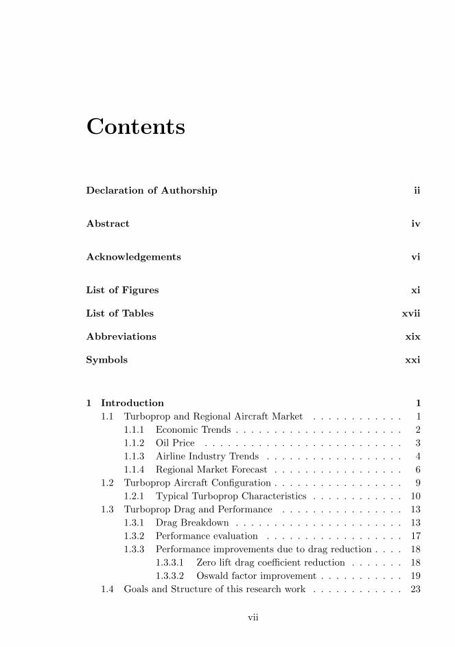
Contents
Declaration of Authorship ii
Abstract iv
Acknowledgements vi
List of Figures xi
List of Tables xvii
Abbreviations xix
Symbols xxi
1 Introduction 1
1.1 Turboprop and Regional Aircraft Market . . . . . . . . . . . . 1
1.1.1 Economic Trends . . . . . . . . . . . . . . . . . . . . . . 2
1.1.2 Oil Price . . . . . . . . . . . . . . . . . . . . . . . . . . 3
1.1.3 Airline Industry Trends . . . . . . . . . . . . . . . . . . 4
1.1.4 Regional Market Forecast . . . . . . . . . . . . . . . . . 6
1.2 Turboprop Aircraft Configuration . . . . . . . . . . . . . . . . . 9
1.2.1 Typical Turboprop Characteristics . . . . . . . . . . . . 10
1.3 Turboprop Drag and Performance . . . . . . . . . . . . . . . . 13
1.3.1 Drag Breakdown . . . . . . . . . . . . . . . . . . . . . . 13
1.3.2 Performance evaluation . . . . . . . . . . . . . . . . . . 17
1.3.3 Performance improvements due to drag reduction . . . . 18
1.3.3.1 Zero lift drag coefficient reduction . . . . . . . 18
1.3.3.2 Oswald factor improvement . . . . . . . . . . . 19
1.4 Goals and Structure of this research work . . . . . . . . . . . . 23
vii
Contents
2 Airfoil Design and Optimization 25
2.1 Introduction . . . . . . . . . . . . . . . . . . . . . . . . . . . . . 25
2.2 Geometry Parameterization . . . . . . . . . . . . . . . . . . . . 27
2.2.1 Bezier Curves . . . . . . . . . . . . . . . . . . . . . . . . 28
2.2.2 Legendre Polynomials . . . . . . . . . . . . . . . . . . . 29
2.2.3 PARSEC Method . . . . . . . . . . . . . . . . . . . . . . 34
2.3 Optimization Algorithms . . . . . . . . . . . . . . . . . . . . . 35
2.3.1 Gradients Based . . . . . . . . . . . . . . . . . . . . . . 37
2.3.2 Genetic Algorithm . . . . . . . . . . . . . . . . . . . . . 37
2.3.3 NashGA Algorithm . . . . . . . . . . . . . . . . . . . . . 37
2.4 Constraints Selection . . . . . . . . . . . . . . . . . . . . . . . . 39
2.4.1 Geometrical constraints . . . . . . . . . . . . . . . . . . 39
2.4.2 Aerodynamic constraints . . . . . . . . . . . . . . . . . 40
2.5 Objective function . . . . . . . . . . . . . . . . . . . . . . . . . 41
2.6 Solvers . . . . . . . . . . . . . . . . . . . . . . . . . . . . . . . . 42
2.7 Applications . . . . . . . . . . . . . . . . . . . . . . . . . . . . . 43
2.7.1 Single case optimization . . . . . . . . . . . . . . . . . . 44
2.7.2 Turboprop aircraft airfoil in cruise and climb . . . . . . 49
2.7.3 Turboprop aircraft airfoil in cruise, climb and stall . . . 52
2.7.4 High efficiency airfoil applied to fan design . . . . . . . 57
2.7.5 High efficiency airfoil applied to wind turbine . . . . . . 60
3 Aircraft Components Design and Optimization 65
3.1 Introduction . . . . . . . . . . . . . . . . . . . . . . . . . . . . . 65
3.2 NURBS parameterization . . . . . . . . . . . . . . . . . . . . . 68
3.2.1 B-Splines . . . . . . . . . . . . . . . . . . . . . . . . . . 69
3.2.2 NURBS Curves and Surfaces . . . . . . . . . . . . . . . 70
3.2.3 NURBS in MATLab environment . . . . . . . . . . . . . 73
3.3 Objective Function . . . . . . . . . . . . . . . . . . . . . . . . . 74
3.4 Turboprop Aerodynamic Analysis . . . . . . . . . . . . . . . . . 77
3.5 Applications . . . . . . . . . . . . . . . . . . . . . . . . . . . . . 82
3.5.1 Aircraft Fuselage nose . . . . . . . . . . . . . . . . . . . 83
3.5.2 Wing-Fuselage junction . . . . . . . . . . . . . . . . . . 89
3.5.3 Undercarriage vane . . . . . . . . . . . . . . . . . . . . . 95
3.5.4 Performance improvement due to Optimization . . . . . 96
3.6 Winglet Design . . . . . . . . . . . . . . . . . . . . . . . . . . . 99
3.6.1 Aerodynamics of the winglet . . . . . . . . . . . . . . . 100
3.6.2 Turboprop winglet design . . . . . . . . . . . . . . . . . 102
3.6.3 Performance improvements due to Winglet . . . . . . . 114
4 Vertical Tail Design 119
4.1 Introduction . . . . . . . . . . . . . . . . . . . . . . . . . . . . . 119
viii

Contents
4.1.1 Semi-Empirical Methods . . . . . . . . . . . . . . . . . . 122
4.2 CFD Approach . . . . . . . . . . . . . . . . . . . . . . . . . . . 129
4.2.1 Test Cases . . . . . . . . . . . . . . . . . . . . . . . . . . 129
4.3 Parametric Analysis on typical turboprop geometries . . . . . . 137
4.3.1 Preliminary CFD analyses . . . . . . . . . . . . . . . . . 138
4.3.2 CFD model analyses and discussion . . . . . . . . . . . 139
4.3.2.1 Isolated Vertical tail . . . . . . . . . . . . . . . 144
4.3.2.2 Fuselage Effect . . . . . . . . . . . . . . . . . . 146
4.3.2.3 Wing Effect . . . . . . . . . . . . . . . . . . . 147
4.3.2.4 Horizontal tailplane effect . . . . . . . . . . . . 150
4.3.3 Rudder Effect . . . . . . . . . . . . . . . . . . . . . . . . 152
4.3.3.1 Isolated vertical tail with rudder Effect . . . . 153
4.3.3.2 Body Effect on vertical tail with rudder . . . . 153
4.3.3.3 Wing Effect on vertical tail with rudder . . . . 155
4.3.3.4 Horizontal tailplane Effect on vertical tail withrudder . . . . . . . . . . . . . . . . . . . . . . . 156
4.3.3.5 Final remarks on rudder Effect . . . . . . . . . 158
4.4 New Vertical Tail Design Method . . . . . . . . . . . . . . . . . 161
4.4.1 Isolated vertical tailplane lift curve slope . . . . . . . . . 162
4.4.2 Fuselage correction factor . . . . . . . . . . . . . . . . . 163
4.4.3 Wing correction factor . . . . . . . . . . . . . . . . . . . 164
4.4.4 Horizontal tailplane correction factor . . . . . . . . . . . 165
4.4.5 Rudder correction factor . . . . . . . . . . . . . . . . . . 168
4.5 Applications . . . . . . . . . . . . . . . . . . . . . . . . . . . . . 168
5 Conclusions 173
A Airfoil Optimization Tool 177
A.1 Input from GUI . . . . . . . . . . . . . . . . . . . . . . . . . . . 178
A.2 Input from file . . . . . . . . . . . . . . . . . . . . . . . . . . . 187
A.3 AOT Output . . . . . . . . . . . . . . . . . . . . . . . . . . . . 188
B VeDSC - Tables of configurations 189
Bibliography 197
ix


List of Figures
1.1 World real GDP growth %, 2011 . . . . . . . . . . . . . . . . . 2
1.2 Commercial Aircraft orders and GDP growth . . . . . . . . . . 3
1.3 Oil Price forecast . . . . . . . . . . . . . . . . . . . . . . . . . . 4
1.4 U.S. Airline segmentation profitability/loss . . . . . . . . . . . 6
1.5 Long term demand for Large Turboprop, ATR Forecast, March2010 . . . . . . . . . . . . . . . . . . . . . . . . . . . . . . . . . 7
1.6 Turboprop Forecast,Delivery Stream (2010-2029) . . . . . . . . 8
1.7 Turboprop Forecast,Delivery Stream (2010-2029) . . . . . . . . 8
1.8 Regional Turboprop Industry Consolidation . . . . . . . . . . . 10
1.9 ATR-72 and DASH8-Q400 aircraft. . . . . . . . . . . . . . . . . 11
1.10 ATR-72-500/600 Composite Materials . . . . . . . . . . . . . . 11
1.11 ATR-72 3-View . . . . . . . . . . . . . . . . . . . . . . . . . . . 14
1.12 ATR-72 drag breakdown main sources . . . . . . . . . . . . . . 16
1.13 ATR-72 drag contribution . . . . . . . . . . . . . . . . . . . . . 16
1.14 ATR-72 drag polar . . . . . . . . . . . . . . . . . . . . . . . . . 17
1.15 Turboprop power ratio . . . . . . . . . . . . . . . . . . . . . . . 18
1.16 Maximum true airspeed variation due to zero lift drag coefficient 19
1.17 Fuel consumption variation due to zero lift drag coefficient . . . 20
1.18 Maximum true airspeed variation due to Oswald factor e . . . 21
1.19 Fuel consumption variation due to Oswald factor e . . . . . . . 21
1.20 Maximum rate of climb variation due to Oswald factor e . . . . 22
1.21 Ceiling altitude variation due to Oswald factor e . . . . . . . . 22
2.1 Direct Numerical Optimization scheme. . . . . . . . . . . . . . 26
2.2 Single 3rd order Bezier curve. . . . . . . . . . . . . . . . . . . . 28
2.3 Bezier airfoil geometry reconstruction. . . . . . . . . . . . . . . 29
2.4 Bezier airfoil approximation, piecewise technique. . . . . . . . . 30
2.5 Legendre polynomials. . . . . . . . . . . . . . . . . . . . . . . . 32
2.6 Legendre’s airfoil modification, small perturbation technique. . 33
2.7 PARSEC variable definition. . . . . . . . . . . . . . . . . . . . . 34
2.8 PARSEC airfoil reconstruction. . . . . . . . . . . . . . . . . . . 36
2.9 Nash genetic algorithm structure. . . . . . . . . . . . . . . . . . 39
xi
List of Figures
2.10 NACA 23015 lift coefficient, solvers comparison, M = 0.1,Re = 2.6 106. . . . . . . . . . . . . . . . . . . . . . . . . . . . . 43
2.11 Automated structured airfoil mesh used in the optimization loop. 44
2.12 AOT single optimization of Cd, results, fixed transition. . . . . 46
2.13 AOT single optimization ofC
3/2lCd
, results, fixed transition. . . . 48
2.14 AOT single optimization of Clmax , results, fully turbulent flow. 50
2.15 AOT multi-optimization of Cruise Cdmin and Climb maximumefficiency, results, fixed transition, M = 0.43, Re = 19.5 106. . . 52
2.16 AOT multi-optimization in Cruise, Climb and Stall Conditions,airfoils comparison. . . . . . . . . . . . . . . . . . . . . . . . . . 54
2.17 Example of turboprop wing designed with otpimized airfoil incruise, climb and stall condition. . . . . . . . . . . . . . . . . . 55
2.18 AOT multi-optimization in Cruise, Climb and Stall Conditions,results. . . . . . . . . . . . . . . . . . . . . . . . . . . . . . . . . 56
2.19 AOT high efficiency airfoil, aerodynamic results, fixed transition. 58
2.20 Fan of wind-tunell at DII. . . . . . . . . . . . . . . . . . . . . . 59
2.21 AOT Variable assignment scheme. . . . . . . . . . . . . . . . . 60
2.22 Original and Optimized NashGa Airfoils. Example of solutions. 62
2.23 AOT Aerodynamic efficiency vs. drag coefficient for both notconstrained and constrained case. . . . . . . . . . . . . . . . . . 63
3.1 Optimization strategy scheme. MATLab Environment. . . . . . 67
3.2 NURBS curve, an example. . . . . . . . . . . . . . . . . . . . . 71
3.3 NURBS surface, an example. . . . . . . . . . . . . . . . . . . . 71
3.4 NURBS Curves and Surface example and modifications. . . . . 75
3.5 NURBS example of Coons surface creation. . . . . . . . . . . . 76
3.6 NURBS example wing-fuselage reconstruction. . . . . . . . . . 76
3.7 ATR-72 model for the aerodynamic analysis. . . . . . . . . . . 77
3.8 ATR-72 wing body mesh components. . . . . . . . . . . . . . . 78
3.9 Cp distribution along upper, middle and lower streamlines,Cruise condition. . . . . . . . . . . . . . . . . . . . . . . . . . . 80
3.10 Cp contour, Cruise condition. . . . . . . . . . . . . . . . . . . . 80
3.11 Cf distribution along upper, middle and lower streamlines,Cruise condition. . . . . . . . . . . . . . . . . . . . . . . . . . . 81
3.12 Cf contour, Cruise condition. . . . . . . . . . . . . . . . . . . . 81
3.13 Example of NURBS control points and boundary curves, Kar-man component application, rear view. . . . . . . . . . . . . . . 82
3.14 Example of NURBS surface, Karman component application,rear view. . . . . . . . . . . . . . . . . . . . . . . . . . . . . . . 83
3.15 Aircraft nose geometry involved in the optimization loop. . . . 84
3.16 Aircraft nose NURBS variation in height and length. . . . . . . 84
3.17 Aircraft nose sections comparison. . . . . . . . . . . . . . . . . 86
xii
List of Figures
3.18 Aircraft nose drag coefficient during optimization process. . . . 86
3.19 Aircraft nose pressure coefficient comparison, Original and Op-timized geometry. . . . . . . . . . . . . . . . . . . . . . . . . . . 87
3.20 Cp distribution along upper, middle and lower streamlines,Cruise condition. Comparison of Original and Optimized nosegeometry. . . . . . . . . . . . . . . . . . . . . . . . . . . . . . . 88
3.21 ATR-72 and Bombardier Dash Q-400 Nose geometry. . . . . . . 88
3.22 NURBS and control points for Karman optimization. . . . . . . 89
3.23 Karman geometry comparison, Original (green), Optimized (red). 91
3.24 Karman main sections geometry comparison, Original (green),Optimized (red). . . . . . . . . . . . . . . . . . . . . . . . . . . 92
3.25 Pressure and friction coefficient on the Original and OptimizedKarman geometry. . . . . . . . . . . . . . . . . . . . . . . . . . 93
3.26 Cp and Cf distribution along upper streamline, Cruise condition.Comparison of Original and Optimized karman geometry. . . . 94
3.27 ATR-72 and Bombardier Dash Q-400. . . . . . . . . . . . . . . 94
3.28 NURBS for Fairing component optimization. . . . . . . . . . . 95
3.29 Original and Optimized Fairing geometry and pressure coefficient. 97
3.30 Typical turboprop mission profile. . . . . . . . . . . . . . . . . 101
3.31 Vorticity due to finite wing. . . . . . . . . . . . . . . . . . . . . 101
3.32 Winglet’s main design parameters. . . . . . . . . . . . . . . . . 102
3.33 Reference wing geometry. . . . . . . . . . . . . . . . . . . . . . 103
3.34 Reference wing mesh and pressure coefficient, Cruise. . . . . . . 104
3.35 Reference wing, square lift coefficient versus induced drag, Climbcondition. . . . . . . . . . . . . . . . . . . . . . . . . . . . . . . 105
3.36 Reference wing lift and wing span loading distribution, Climbcondition. . . . . . . . . . . . . . . . . . . . . . . . . . . . . . . 106
3.37 Winglet design parameters. . . . . . . . . . . . . . . . . . . . . 107
3.38 Wing lift coefficient distribution and Oswald factor variationdue to toe angle. . . . . . . . . . . . . . . . . . . . . . . . . . . 110
3.39 Effect of cant and winglet height on ew. . . . . . . . . . . . . . 111
3.40 Effect of cant and winglet height on AR. . . . . . . . . . . . . . 111
3.41 Effect of cant and winglet height on ARew. . . . . . . . . . . . 112
3.42 Effect of cant and winglet height on Swet/Sref . . . . . . . . . . 112
3.43 Effect of winglet sweep on ew. . . . . . . . . . . . . . . . . . . . 113
3.44 Wing and Winglet geometry comparison. . . . . . . . . . . . . 114
3.45 Winglet pressure coefficient distribution. . . . . . . . . . . . . . 115
3.46 Comparison of lift coefficient and wing span loading distributionfor reference wing and optimal winglet, Climb condition. . . . . 116
3.47 Aircraft drag coefficient variation due to winglet. . . . . . . . . 117
4.1 ATR-42 three-view. . . . . . . . . . . . . . . . . . . . . . . . . . 124
xiii
List of Figures
4.2 Sideforce due to sideslip coefficient as a function of vertical tailaspect ratio. . . . . . . . . . . . . . . . . . . . . . . . . . . . . . 125
4.3 Sideforce due to sideslip coefficient as a function of wing position.126
4.4 Sideforce due to sideslip coefficient as a function of wing aspectratio. . . . . . . . . . . . . . . . . . . . . . . . . . . . . . . . . . 127
4.5 Sideforce due to sideslip coefficient as a function of horizontaltailplane position. . . . . . . . . . . . . . . . . . . . . . . . . . 127
4.6 Sideforce due to sideslip coefficient as a function of tailplanes’relative size. . . . . . . . . . . . . . . . . . . . . . . . . . . . . . 128
4.7 Sideforce due to sideslip coefficient as a function of fuselage depth.128
4.8 CAD drafting of the model of NACA Report 540. . . . . . . . . 131
4.9 Mesh of NACA 540 test case. . . . . . . . . . . . . . . . . . . . 131
4.10 Results of the mid-wing combination of NACA Report 540. . . 132
4.11 CAD drafting of the model of NACA TN-730. . . . . . . . . . . 133
4.12 Mesh of NACA TN-730 test case. . . . . . . . . . . . . . . . . . 133
4.13 Results of the body-wing-fin combination of NACA TN-730. . . 134
4.14 CAD drafting of the model of NACA Report 1049. . . . . . . . 135
4.15 Mesh of NACA 1049 test case. . . . . . . . . . . . . . . . . . . 135
4.16 Results of the fuselage-wing-vertical combination of NACAReport 1049. . . . . . . . . . . . . . . . . . . . . . . . . . . . . 136
4.17 CAD drafting of the CFD model. . . . . . . . . . . . . . . . . . 138
4.18 The configurations of the CFD model. . . . . . . . . . . . . . . 140
4.19 The CAD model imported in Star-CCM+. . . . . . . . . . . . . 141
4.20 Aerodynamic coefficients as a function of base size and numberof cells for the configuration of Fig. 4.21. . . . . . . . . . . . . . 141
4.21 Mesh on the model used for the base size trend study. . . . . . 142
4.22 CPUs scalability for a body-vertical configuration with 1800000polyhedral cells. . . . . . . . . . . . . . . . . . . . . . . . . . . . 142
4.23 Influence of the Reynolds number on the complete aircraft model.142
4.24 Block shape that defines the fluid domain around the model. . 143
4.25 Isolated vertical tail geometries analyzed. . . . . . . . . . . . . 144
4.26 Lift gradient vs. aspect ratio for the isolated vertical tailplanesand sideforce coefficient. . . . . . . . . . . . . . . . . . . . . . . 145
4.27 Configuration involved in the analysis of the effect of the fuselage.146
4.28 Streamlines approaching the vertical tailplane. . . . . . . . . . 146
4.29 Lift gradient vs. aspect ratio for the isolated vertical tailplanesand sideforce coefficient. . . . . . . . . . . . . . . . . . . . . . . 147
4.30 Configurations involved in the analysis of the effect of the wing. 148
4.31 Effect of the wing at various aspect ratios and positions, withtwo vertical tailplanes. . . . . . . . . . . . . . . . . . . . . . . . 148
4.32 Resume of wing effect. . . . . . . . . . . . . . . . . . . . . . . . 149
4.33 Qualitatively representation of the windward wing-tip vortices. 150
xiv

List of Figures
4.34 Horizontal tailplanes’ configuration. . . . . . . . . . . . . . . . 151
4.35 Horizontal tailplane position effect . . . . . . . . . . . . . . . . 152
4.36 Effect of the relative size of tailplanes. . . . . . . . . . . . . . . 153
4.37 Configurations involved in the analysis of the relative size ofthe tailplanes. . . . . . . . . . . . . . . . . . . . . . . . . . . . . 154
4.38 Configurations involved in the rudder effect. . . . . . . . . . . . 155
4.39 The vertical tailplane and the NACA 0012 airfoil with thetrailing edge rotated to simulate a rudder deflection. . . . . . . 156
4.40 Linearity of the lateral force coefficient at several angles ofsideslip and rudder deflection for the isolated vertical tailplane. 156
4.41 The lateral force coefficient vs. rudder deflection at zero sideslipangle for the isolated vertical tailplane. . . . . . . . . . . . . . . 157
4.42 Streamlines showing the asymmetric flow path in the rear partof the fuselage. . . . . . . . . . . . . . . . . . . . . . . . . . . . 157
4.43 Values of the vertical tail lateral force coefficient at severalangles of sideslip. . . . . . . . . . . . . . . . . . . . . . . . . . . 158
4.44 Comparison of the three wing-body-vertical combinations andthe body vertical combination. . . . . . . . . . . . . . . . . . . 158
4.45 Streamlines around tailplanes for body-mounted and tip-mountedhorizontal stabilizer configurations. . . . . . . . . . . . . . . . . 160
4.46 Comparison among 3 angles of sideslip and 2 angles of rudderdeflection for the mid wing, body-mounted configuration. . . . 160
4.47 Definition of the vertical stabilizer . . . . . . . . . . . . . . . . 162
4.48 Definitions for KF . . . . . . . . . . . . . . . . . . . . . . . . . 163
4.49 KF coefficient . . . . . . . . . . . . . . . . . . . . . . . . . . . . 163
4.50 Definitions for KW . . . . . . . . . . . . . . . . . . . . . . . . . 164
4.51 KW coefficient . . . . . . . . . . . . . . . . . . . . . . . . . . . 164
4.52 Definitions for KHp . . . . . . . . . . . . . . . . . . . . . . . . . 166
4.53 KHp coefficient . . . . . . . . . . . . . . . . . . . . . . . . . . . 166
4.54 Definitions for KHs . . . . . . . . . . . . . . . . . . . . . . . . . 167
4.55 KHs coefficient . . . . . . . . . . . . . . . . . . . . . . . . . . . 167
4.56 CFD model application. . . . . . . . . . . . . . . . . . . . . . . 169
4.57 P2012 Geometry. . . . . . . . . . . . . . . . . . . . . . . . . . . 171
4.58 P2012 CFD Analysis. . . . . . . . . . . . . . . . . . . . . . . . 171
5.1 Future Large Turbopropeller. . . . . . . . . . . . . . . . . . . . 175
A.1 AOT main GUI. . . . . . . . . . . . . . . . . . . . . . . . . . . 177
A.2 AOT Import airfoil GUI. . . . . . . . . . . . . . . . . . . . . . 178
A.3 AOT Airfoil to optimize dialog GUI. . . . . . . . . . . . . . . . 178
A.4 Example of airfoil coordinates for AOT. . . . . . . . . . . . . . 179
A.5 AOT Parameterization method GUI. . . . . . . . . . . . . . . . 179
xv

List of Figures
A.6 AOT Boundaries and Constraints GUI. . . . . . . . . . . . . . 180
A.7 AOT Details of Bezier boundary settings. . . . . . . . . . . . . 181
A.8 AOT Details of constraints settings. . . . . . . . . . . . . . . . 182
A.9 AOT Details of Legendre boundary settings. . . . . . . . . . . . 183
A.10 AOT Details of PARSEC boundary settings. . . . . . . . . . . 184
A.11 AOT Optimization algorithm GUI. . . . . . . . . . . . . . . . . 184
A.12 AOT Objective function multi condition GUI for GA and GBalgorithm. . . . . . . . . . . . . . . . . . . . . . . . . . . . . . . 185
A.13 AOT Objective function single condition GUI for NashGA. . . 186
A.14 AOT Text file configuration, example of settings. . . . . . . . . 187
A.15 AOT Output figures. . . . . . . . . . . . . . . . . . . . . . . . . 188
xvi

List of Tables
1.1 Airline Industry net profits (Billions U.S. dollars). . . . . . . . 5
1.2 Fleet growth forecast. . . . . . . . . . . . . . . . . . . . . . . . 6
1.3 Large turboprop aircraft main characteristics. . . . . . . . . . . 12
1.4 ATR-72 main characteristics and conditions. . . . . . . . . . . . 15
1.5 ATR-72 Estimated performance. . . . . . . . . . . . . . . . . . 18
2.1 PARSEC parameters definition. . . . . . . . . . . . . . . . . . . 34
2.2 AOT geometrical constraints. . . . . . . . . . . . . . . . . . . . 40
2.3 AOT aerodynamic constraints. . . . . . . . . . . . . . . . . . . 40
2.4 Objective function scalar values. . . . . . . . . . . . . . . . . . 42
2.5 Reference aerodynamic conditions. . . . . . . . . . . . . . . . . 44
2.6 AOT settings, low drag in cruise airfoil optimization. . . . . . . 45
2.7 AOT settings, high efficiency in climb airfoil optimization. . . . 47
2.8 AOT settings, maximum lift coefficient in stall airfoil optimization. 49
2.9 AOT settings, Cruise Cdmin and Climb maximum efficiencyoptimization. . . . . . . . . . . . . . . . . . . . . . . . . . . . . 51
2.10 AOT results, Cruise Cdmin and Climb maximum efficiency opti-mization. . . . . . . . . . . . . . . . . . . . . . . . . . . . . . . 51
2.11 AOT settings, Cruise Cdmin and Stall Clmax optimization. . . . 53
2.12 AOT results, Cruise Cdmin Climb maximum efficiency, Stall liftcoefficient. . . . . . . . . . . . . . . . . . . . . . . . . . . . . . . 55
2.13 AOT settings, Wind-Tunell Fan high efficiency airfoil optimization. 57
2.14 AOT settings, Maximum Airfoil efficiency optimization. . . . . 61
3.1 Reference aerodynamic conditions . . . . . . . . . . . . . . . . 78
3.2 Wing-Body reference analysis, Cruise Condition. . . . . . . . . 79
3.3 Fuselage Nose Optimization, Cruise condition. . . . . . . . . . . 85
3.4 Wing-fuselage junction Optimization, Cruise condition. . . . . 90
3.5 Fairing Optimization, Cruise condition. . . . . . . . . . . . . . 96
3.6 Optimized results, drag coefficient reduction for Nose, Karmanand Fairing components. . . . . . . . . . . . . . . . . . . . . . . 98
3.7 Original and Optimized Aircraft performance comparison. . . . 98
3.8 Reference wing geometry. . . . . . . . . . . . . . . . . . . . . . 103
xvii

List of Tables
3.9 Winglet reference parameters. . . . . . . . . . . . . . . . . . . . 108
3.10 Winglet parameters variation range. . . . . . . . . . . . . . . . 108
3.11 Results for the optimal winglet. . . . . . . . . . . . . . . . . . . 113
3.12 Original and Winglet Aircraft performance comparison. . . . . 115
4.1 ATR-42 geometric parameters. . . . . . . . . . . . . . . . . . . 124
4.2 Results comparison for the ATR-42, DATCOM and ESDUmethod. . . . . . . . . . . . . . . . . . . . . . . . . . . . . . . . 125
4.3 Mesh and physics data for NACA Report 540. . . . . . . . . . . 130
4.4 Mesh and physics data for NACA TN-730. . . . . . . . . . . . . 130
4.5 Mesh size (in % base size) for NACA TN-730. . . . . . . . . . . 132
4.6 Mesh and physics data for NACA Report 1049. . . . . . . . . . 134
4.7 Mesh size (in % base size) for NACA Report 1049. . . . . . . . 135
4.8 Fuselage parameters. CFD Models and reference turboprop. . . 137
4.9 Vertical tailplane parameters. CFD Models and reference tur-boprop. . . . . . . . . . . . . . . . . . . . . . . . . . . . . . . . 137
4.10 Horizontal tailplane parameters. CFD Models and referenceturboprop. . . . . . . . . . . . . . . . . . . . . . . . . . . . . . . 138
4.11 Mesh and physics data for the CFD model. . . . . . . . . . . . 139
4.12 Mesh size (in % base size) for the CFD model. . . . . . . . . . 143
4.13 Effects of the tip-mounted horizontal tail on different verticaltail aspect ratios. . . . . . . . . . . . . . . . . . . . . . . . . . . 151
4.14 Fuselage interference factors. . . . . . . . . . . . . . . . . . . . 155
4.15 Wing interference factors. . . . . . . . . . . . . . . . . . . . . . 159
4.16 Tip-mounted horizontal tail interference factors. . . . . . . . . 159
4.17 Body-mounted horizontal tail interference factors. . . . . . . . . 159
4.18 CFD Model data. . . . . . . . . . . . . . . . . . . . . . . . . . . 169
4.19 CFD Model results. . . . . . . . . . . . . . . . . . . . . . . . . 169
4.20 ATR-42 data. . . . . . . . . . . . . . . . . . . . . . . . . . . . . 170
4.21 ATR-42 results. . . . . . . . . . . . . . . . . . . . . . . . . . . . 170
4.22 P2012 data. . . . . . . . . . . . . . . . . . . . . . . . . . . . . . 170
4.23 P2012 results. . . . . . . . . . . . . . . . . . . . . . . . . . . . . 171
xviii
Abbreviations
AEO All Engine Operative
AOT Airfoil Optimization Tool
CAD Computer Aided Design
CFD Computetional Fluid Dynamic
CPU Central Processing Unit
DII Dipartimento di Ingegneria Industriale
DNO Direct Numerical Optimization
EASA European Aviation Safety Agency
ESDU Engineering Science Data Unit
FAR Federal Aviation Regulations
FEM Finite Element Method
GB Gradient Based
GA Genetic Algorithm
ID Inverse Design
MATLab Matrix Laboratory (a MathWorks software)
N-S Navier Stokes
NACA National Advisory Committee for Aeronautics
NASA National Aeronautics and Space Administration
NURBS Non Uniform Rational B-Spline
OEI One Engine Inoperative
SCoPE Sistema Coperativo
Per Elaborazioni Scientifiche Multidisciplinari
USAF DATCOM United States Air Force Data Compendium
VeDSC Vertical tail Design Stability and Control
xix


Symbols
A aspect ratio
AR aspect ratio
CD 3-D Drag coefficient
CL 3-D Lift coefficient
CL 3-D Rolling moment coefficient
CM 3-D Pitching moment coefficient
CN 3-D Yawing moment coefficient
CY 3-D Sideforce coefficient
Cd 2-d Drag coefficient
Cf friction coefficient
Cl 2-d Lift coefficient
Cm 2-d Pitching moment coefficient
Cp pressure coefficient
P0 maximum shaft horsepower
R/C rate of climb
S wing surface
SH horizontal tailplane surface
SV vertical tailplane surface
STO take-off distance
SLAN landing distance
SHP shaft horsepower
VEF engine failure speed
VMC minimum control speed
VTAS true airspeed
xxi

Symbols
2r fuselage diameter at vertical tail aerodynamic center
b wing span
bH horizontal tailplane span
bV vertical tailplane span
bv1 vertical tailplane span extended on fuselage centerline
c wing chord
cantw winglet cant angle
cmac mean aerodynamic chord
cv vertical tailplane chord
df fuselage diameter
e oswald factor
ew wing induced drag factor
hw winglet height
rw winglet radius
rf fuselage half equivalent diameter
toew winglet toe angle
zw wing position
∆w winglet sweep angle
Λ wing and tailplane sweep angle
α angle of attack
β angle of sideslip
εw winglet twist angle
ηp propeller efficiency
θ fuselage upsweep angle
λ taper ratio
λw winglet taper ratio
xxii