Embed Size (px)
Citation preview

Development of Low-Exergy-Loss, High-Efficiency Chemical Engines
Investigators
Chris F. Edwards, Associate Professor, Mechanical Engineering; Shannon L. Miller,
Matthew N. Svrcek, Sankaran Ramakrishnan, Graduate Researchers, Stanford University.
Abstract
In this report we describe our continuing efforts to develop ultra-high efficiency
chemical engines. This work is divided into two branches, one for batch processes and
one for steady flow. Both are based on what we have termed the ‘extreme-states
principle’—that reducing efficiency losses due to unrestrained combustion requires
performing the reaction at the highest possible internal energy state.
In the exploration of batch processes, we previously completed construction of a free-
piston device capable of hosting combustion at volumetric compression ratios in excess
of 100:1, with the goal of achieving 60% thermal efficiency. Our work for this past year
has focused on three areas. First, we characterized the non-reacting performance of the
device. A quantitative measure of combined heat and mass transfer losses during the
compression-expansion process was obtained. Second, light-load combustion was
introduced (equivalence ratio ~ 0.3), and indicated thermal efficiency was measured for
compression ratios from 30:1 to 100:1. In this first pass, efficiency peaked at 50.5%.
Third, full-bore optical access in the end-wall of the combustor was used to perform
high-speed schlieren and direct photography of the spray and combustion. A study of
non-reacting spray penetration and dispersion was completed, and a study of combusting
spray penetration, dispersion, and ignition delay has begun.
Taken together, these three areas of progress represent a systematic approach to
achieving our goal of 60% efficiency. Comparing the measured thermal efficiency to an
ideal cycle, we identified two main areas of losses. The first is the heat and mass transfer
measured in the non-reacting experiments and associated with the current device
geometry and sealing technique. The second is due to un-optimized combustion. The
optical access work addresses this latter point, as we begin to study the combustion event
in detail.
The extreme-states principle has also been shown to apply to steady-flow engines. A
number of differences from the batch engine, i.e. turbomachinery irreversibility, material
temperature limit, and the availability of kinetic energy as an additional parameter,
impact the feasible optimal possibilities. Our recent work showed that a temperature-
constrained combustion process at feasible extreme states is the optimal choice for
efficiency maximization, as opposed to the conventional choice of a Brayton cycle with
reduced pressure ratios. Further work includes the control of kinetic energy, thus
extending the extreme-states principle to both stationary and aviation steady-flow
engines.

Introduction
A majority of energy uses today involve the transformation of chemical bond energy
to work, including transportation, power generation, and industrial applications.
Improving the efficiency of engines that perform these chemical energy transformations
is likely to be a necessary part of any solution to climate change and energy security. Our
effort focuses on significantly improving the efficiency of chemical engines by taking a
fundamental approach—we start with purely thermodynamic considerations, determine
where efficiency losses occur, and attempt to identify and investigate solutions to these
losses.
In our first GCEP project, taking this approach led to the identification of an extreme-
states principle for combustion engines: The only way to reduce the efficiency loss due
to unrestrained reaction in an internal combustion engine is to conduct the energy
conversion at the highest-possible state of energy density [1]. In this project, we
undertake an implementation of the extreme states principle for batch processes (e.g.
piston-cylinder engines) by investigating the feasibility of operating at compression ratios
of 100:1 or greater. Combustion at such states requires a very different engine design—
most likely free-piston with electromagnetic extraction. As a first step, we identified the
following key research issues: whether combustion could be successfully conducted
(initiated, phased, and completed) under such conditions, and whether the indicated
efficiency after real-world-implementation losses would be sufficient to warrant
development of such a class of engines.
Development of the above work for a batch process followed the logic path of
thermodynamically defining the optimal process, identifying the key parameters for ultra-
high efficiency operation, and then implementing and testing in hardware. We are
following the same path for the other major class of chemical engines: steady-flow, such
as gas turbines. This branch of our work is currently in the phase of thermodynamic
analysis and optimization—developing the analogous extreme states principle for steady-
flow devices. This report details progress made in both of these efforts over the past
year.
Progress and Results
Demonstration of Low-Irreversibility Combustion by Extreme Compression
The extreme compression device is shown schematically in Figure 1. A free piston is
accelerated down the cylinder bore, driven by compressed air from a reservoir via a fast-
acting poppet valve. Near the end of its stroke, the piston enters a forged steel combustor
section, that contains ports for multiple diesel fuel injectors and a pressure transducer. A
sapphire window is mounted in the end-wall of the combustor, providing full-bore optical
access. The cylinder stroke is chosen to be around 2.5 meters to reduce surface-to-
volume ratio at the minimum volume (top dead center, or TDC). The combination of
high piston speed and high pressure eliminates the possibility of using traditional
pressure-energized, oil-lubricated piston seals. Our current strategy uses fixed graphite
rings, the diameter of which is within very close tolerance to the cylinder bore—in effect
using clearance control between the ring and wall to provide the pressure drop across the
piston. Piston position during a run is determined by magnetic sensors distributed along

the length of the cylinder. Since the time of the last GCEP report we have added an
optical position sensor, similar to an optical encoder, near the combustor section to
provide high accuracy piston position measurements near TDC. Piston position,
synchronized with pressure data, provides the indicated work output of the device. Fuel
injection is via a high-pressure, common-rail Bosch Diesel pump and injectors, with
custom nozzle tips that allow a variety of injection strategies. Our previous GCEP report
provides further detail about the design of the experiment [2].
Optical sensing section
Ferrous washer
Clearance control ring
Airreservoir,70 bar
Fast-acting poppet valve assembly
2.5 m long cylinder
High-speed camera
Free-piston
Optical access
Highpressurefuelinjectors
VR sensors
Optical insert for position sensing
Pressure transducer
Pressuretransducer
2 channel,high-speeddata acquisition
16 channel,multiplexeddata acquisition
High-strength combustor
Injection System: 1500 bar common rail,fuel pump and injector controller
Figure 1: Schematic of the extreme compression device.
At the time of the previous GCEP report, we had completed a handful of initial
experiments demonstrating that the device was capable of operating in the desired space
of compression ratio and piston speed. This put us in a position to use the device over the
past year to begin exploring operation and combustion at extreme-compression
conditions. Our work has been in three main areas: (1) characterization and analysis of
non-reacting performance of the device, (2) preliminary mapping of combustion
performance over the compression ratio range, and (3) use of the full-bore optical access
to begin detailed exploration of the spray and combustion process. Progress in each of
these areas is described below.
Non-Reacting Performance A necessary step toward understanding operation at extreme compression ratios is to
characterize the compression-expansion process in the free-piston device. The first set of
tests demonstrated the ability to repeatably and predictably target compression ratios
from 30 to 100:1. Unlike a traditional slider-crank engine, the piston motion is not
mechanically constrained, but rather depends on the reservoir pressure, the valve opening
profile, and friction forces during the run. Using the clearance-control sealing strategy

mentioned above, our initial tests showed compression ratio repeatability within 1% for
any given initial conditions.
An unexpected discovery was the generation of significant acoustic waves in the
cylinder during compression at high accelerations. The plots in Fig. 2 both show pressure
traces for a compression ratio of 45:1 but with different piston masses and, therefore,
mean piston speeds (90 and 60 m/s on left and right, respectively). Even though the peak
piston speeds are well below sonic, the acceleration is sufficient to generate finite-
amplitude compression waves with the lighter piston. The origin, frequency, and
amplitude of these waves have been confirmed by calculations using the method of
characteristics. We note their significance both because they can be easily suppressed by
increasing the mass of the piston, and because they may provide an opportunity to
engineer a regenerative heating process during the intake stroke using the heat capacity of
the cylinder wall. Inasmuch as we anticipate using a net-adiabatic cooling strategy for
this type of high-efficiency engine, this example serves to illustrate that new,
unanticipated opportunities are likely to be uncovered as we begin systematic studies at
these operating conditions.
58 59 60 61 62 63
20
40
60
80
100
120
140
160
Time (ms)
Pre
ssu
re (
bar)
350 g piston
78 80 82 84 86
20
40
60
80
100
120
140
160
Time (ms)
Pre
ssu
re (
bar)
800 g piston
Figure 2: Pressure vs. time for 45:1 compression ratio; two different
piston masses.
Efficiency loss mechanisms for the device can be divided into two general categories:
those associated with the compression-expansion process, and those associated with the
combustion process. To characterize this first category, a number of experiments were
performed without fuel injection over the operating range of the device. Representative
pressure-volume plots for a few compression ratios are shown in Fig. 3. Also shown is
the pressure-volume path of an isentropic process (the dashed line), on which an ideal
compression and expansion would fall. For the actual device, a combination of heat and
mass transfer cause the experimental pressure-volume trace to fall below this line. The
work integral of the pressure-volume loop provides a quantitative measure of the
combined losses during compression and expansion.

10-2
10-1
0
100
200
300
400
500
Volume (V/V0)
Pre
ssu
re (
bar
)
Isentrope
CR = 30CR = 49.5CR = 71.8CR = 97.1
Figure 3: Non-reacting pressure-volume traces for several
compression ratios.
Figure 4 depicts two ways of thinking about the magnitude of losses—net work
relative to the work invested during the compression stroke, and the fraction of isentropic
peak pressure obtained. Although much work remains to be done on the piston sealing
system, the figure shows that even with the current, passive strategy we are capable of
obtaining a significant fraction of isentropic peak pressure under “motored” (non-
combusting) conditions. For compression ratios below 30:1, more than 95% of isentropic
peak pressure is realized. As compression ratio is increased, this drops off, approaching
85% at 100:1. One should also note that these results are obtained with cold walls, such
that the heat loss from the gas is much more significant than for a conventional engine
with warm walls. So while reducing heat and mass loss are of critical importance for
achieving high efficiency, the current sealing approach is already sufficient to provide
access to the conditions we need to develop the combustion system.
20 40 60 80 100−22
−20
−18
−16
−14
−12
−10
−8
CR
Wnet/W
com
p (
%)
20 40 60 80 10084
86
88
90
92
94
96
CR
Ppeak/P
S (
%)
Figure 4: Compression-expansion net work divided by compression work (left)
and experimental peak pressure as a percentage of isentropic peak pressure (right).

Over this past year we also began analysis work to further understand the
mechanisms of heat and mass loss in the system. While the data shown in the previous
figures provide a reliable, quantitative measure of total loss, there is no way based on our
current measurements to determine experimentally what fraction of the loss is due to
mass transfer or to heat transfer. Computational fluid dynamics modeling of the non-
reacting compression-expansion, in addition to experimental steady-flow testing of piston
blowby are currently underway, and should provide a quantitative assessment of the two
losses.
Initial Combusting Performance During the past year we obtained an initial map of thermal efficiency under relatively
light-load conditions over a range of compression ratios from 30 to 100:1. For this study,
two high-pressure diesel injectors with custom nozzle tips were used with a 1.5 ms
injection time, resulting in an overall equivalence ratio of around 0.3. Injection timing
was triggered by one of the magnetic position sensors to control combustion phasing.
Fuel flow rate was determined by calibration of the injectors as a function of chamber
pressure. Figure 5 below shows typical pressure-volume traces for an air-only run and
for two combusting runs at 60:1 CR. For the combusting case the pressure-volume loop
goes above the isentrope resulting in a positive net-work integral.
10−2
10−1
100
10−1
100
101
102
103
Volume (V/V0)
Pre
ssure
(bar
)
Air
Combustion
Low−Blowby Combustion
Isentrope
Figure 5: Pressure-volume traces for combusting and non-combusting
data at 60:1 CR.
The net work per unit fuel lower heating value gives the indicated first-law efficiency,
which is plotted as the red points in Fig. 6. For this data set, the efficiency peaked at
around 45% before rolling off at higher compression ratios. To put this in context, the
blue line is the ideal reactive Otto cycle efficiency for the same equivalence ratio.

Subtracting the net work loss found on an air-only experiment at a given compression
ratio from the ideal work output results in the black points and fit. By looking at the
efficiency expected just from air losses, one can see that much of the losses, including the
drop in efficiency at high compression ratio, is due to heat and mass transfer for the air
compression-expansion process. The remaining losses we attribute to the un-optimized
combustion system—a combination of phasing, inadequate combustion rate and air
utilization, product gas wall wetting leading to enhanced heat transfer, etc. Stated
another way, the combination of analysis and results indicates that efforts in development
of both the combustion system and the wall interface sealing are warranted, and each is
likely to contribute significantly to realizing our efficiency potential.
0 20 40 60 80 10020
30
40
50
60
70
80
Compression Ratio
Eff
icie
ncy
(%)
Ideal 1st law efficiency
70−80% of 1st law efficiency
Experimental efficiency
Ideal minus air−only losses
Reduced blowby experiment
Figure 6: Cycle efficiency versus compression ratio.
As an illustration of the last point, a single experiment using a special, very-low-
blowby sealing technique was conducted at 60:1 compression ratio. Using this seal, and
a slightly improved method of combustion phasing, an indicated efficiency of 50.5% was
achieved. Although we note that this is indicated efficiency, not brake, and therefore
corresponds to a brake efficiency slightly below 50% when probable mechanical losses
are considered, we also point out that this efficiency was achieved using cold (ambient
temperature) walls, such that the effects of heat loss are much more significant than they
would be in an actual engine. In effect, we are already not far from being able to
demonstrate the possibility of realizing a 50% efficient engine and reiterate that our intent
is to demonstrate the potential to achieve 60%.

Optical Study of Spray and Combustion
During the past year we constructed an optical system for studying the combustion in
detail. A schematic of the optical system is shown in Fig. 7. A collimated beam of 488-
nm laser light reflects off a mirror mounted on the piston, is focused through an
achromatic lens to a schlieren stop and recorded by a high-speed camera. This setup
allows simultaneous recording of schlieren effects from gas density variation in the
cylinder, extinction in the liquid portion of the spray, and direct luminosity from
chemical reaction. In addition, a high-sensitivity photodiode with a UV bandpass filter
detects OH chemiluminescence for defining the start of combustion.
Figure 7: Experimental optics setup.
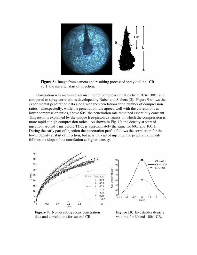
The first study we completed with the optical system was an exploration of fuel spray
penetration and dispersion without chemical reaction. For this study an injector with a
single orifice injected a spray of diesel fuel across the cylinder starting 1ms before TDC.
To prevent combustion, the cylinder was filled with nitrogen rather than air. Schlieren
images of the spray were recorded at 36000 frames per second and post-processed to
define spray penetration (via spray tip location) and dispersion (via spray angle). Figure
8 shows a sample image from the camera and the resulting spray region.
High-speed Camera
Schlieren Stop
Beam Expander and
Spatial Filter
Beamsplitter
Cylinder
Piston with
Mirror
Lens
Sapphire
Window
Fuel Injector
Argon-Ion Laser
Clearance
Volume
Photodiode
θ
L/2
L
Figure 8: Image from camera and resulting processed spray outline. CR
90:1, 0.6 ms after start of injection.
Penetration was measured versus time for compression ratios from 30 to 100:1 and
compared to spray correlations developed by Naber and Siebers [3]. Figure 9 shows the
experimental penetration data along with the correlations for a number of compression
ratios. Unexpectedly, while the penetration rate agreed well with the correlations at
lower compression ratios, above 60:1 the penetration rate remained essentially constant.
This result is explained by the unique free-piston dynamics, in which the compression is
more rapid at high compression ratios. As shown in Fig. 10, the density at start of
injection, around 1 ms before TDC, is approximately the same for 60:1 and 100:1.
During the early part of injection the penetration profile follows the correlation for the
lower density at start of injection, but near the end of injection the penetration profile
follows the slope of the correlation at higher density.
0 0.2 0.4 0.6 0.8 1 1.20
5
10
15
20
25
30
35
40
45
t (ms)
L (
mm
)
30:1
45:1
60:1
70:1
80:1
90:1
100:1
Data CRCorrel.
−1.5 −1 −0.5 0 0.5 1 1.530
40
50
60
70
80
90
100
t (ms)
Gas
Den
sity
(k
g/m
3)
CR = 60:1
CR = 100:1
SOI, EOI
Figure 9: Non-reacting spray penetration Figure 10: In-cylinder density
data and correlations for several CR. vs. time for 60 and 100:1 CR.

Recently we began extending our fundamental, single plume studies to combustion.
Figure 11 shows a sample image of a combusting spray, in this case for a 60:1
compression ratio. In the image one can see: (1) direct luminosity from soot combustion,
(2) sharp density gradients via schlieren at the edge of the reaction zone, and (3) gradients
in the background gas due to in-cylinder fluid mechanics. Spray penetration and
dispersion are determined from the camera images, similar to the non-reacting case. In
addition, a UV-sensitive photodiode detects the start of OH chemiluminscence (which is
not visible in the camera images) allowing for a measurement of ignition delay, as shown
in Fig. 12. This study allows us to further understand the spray combustion behaviour in
the previously unexplored extreme states made accessible by this device, and provides
the basis for designing and optimizing the combustion process that is required for
achieving peak efficiency.
112.15 112.2 112.25 112.3 112.35
0
0.5
1
1.5
2
2.5
3
t (ms)
Lu
min
osity (
A.U
.) Start of Injection (from camera)
Ignition delay
~ 100 µs
Figure 11: Image from camera, CR = Figure 12: Photodiode output vs. time
60:1, 0.94 ms after start of injection. for CR = 60:1.
Theoretical Investigation of Low-Irreversibility, High-Efficiency, Steady-Flow Engines
Over the past few years a thermodynamic framework to define and develop high-
efficiency engine architectures has been developed as part of the research efforts in this
GCEP project. While the initial development was done with emphasis on batch-flow
engines [1], the framework was extended to simple-cycle, gas turbine engines and the key
results were discussed in our previous report [2].
Irreversibility minimization in gas turbine engines follows an extreme-state principle
analogous to the extreme-state principle for the piston-engines. However, unlike piston-
engines, irreversibility inherent in energy transfer as work for gas turbine engines led to a
limited extreme-state (i.e. a limiting pressure ratio for maximum efficiency). This
limiting pressure ratio is a result of irreversibility minimization, and not a pressure limit
obtained from purely material considerations. The variation of this pressure limit with

the extent of irreversibility in the work interactions (polytropic efficiency) is shown in
Fig. 13 for a natural gas/air, gas turbine engine. Figure 14 shows the variation of the total
irreversibility with pressure ratio, for a polytropic efficiency of 0.8 for the engine.
Polytropic Efficiency η
Pre
ssure
Lim
it P
* (
bar
)
0.6 0.65 0.7 0.75 0.8 0.8510
0
101
102
103
0.6 0.65 0.7 0.75 0.8 0.851500
1750
2000
2250
2500
2750
3000
3250
Max
imum
Tem
per
ature
Tm
ax (
K)
Figure 13: Variation of optimal pressure-ratio and peak temperature with polytropic
efficiency.
100
101
102
103
0
0.2
0.4
0.6
0.8
1
1.2
1.4
1.6
1.8
2
Pressure Ratio
Entr
opy G
ener
atio
n (
kJ/
kg
mix
K)
Combustion
Fluid Friction
Total
P*
Figure 14: Trade-off between combustion and compression/expansion work
irreversibility for a polytropic efficiency of 80%.
The optimal, simple-cycle engine is realized by minimizing total irreversibility using
optimal control of energy transfer as work. The cycle is characterized by switching
points based on device polytropic efficiencies and results in a desirable operating
pressure ratio well over the currently existing pressure ratios in engines.

However, the limitation imposed by the maximum temperature on a practical
implementation of the optimal process was recognized in the previous report. Unlike the
conventional solution to this limitation, i.e., reducing pressure ratios and introducing
blade-cooling, the temperature limit was considered as a constraint to the irreversibility
minimization approach and efforts in the past year were focused on this.
In view of addressing a broader category of simple-cycle, steady-flow engines, i.e. the
inclusion of propulsion engines, it was recognized that management of kinetic energy
was key to irreversibility minimization and was also studied in the past year.
Efforts in the Last Year
Material temperature limits have been a severe constraint on practical implementation
of extreme-states in gas-turbine engines. This constraint was not considered in our
analysis so far. Hence, including this constraint to find the optimal engine cycle and
exploring its implications for engine architecture was the first key aspect addressed in the
past year. This approach led to a temperature-limited optimal cycle involving a part of
the combustion process at constant-temperature conditions. This architecture is
noticeably different from the currently existing blade-cooled Brayton-cycle engines and
can lead to significant increase in efficiency of simple-cycle engines.
The second key aspect studied in the past year is the effect of manipulating kinetic
energy in a simple-cycle, steady-flow engine. It was concluded that optimal control of
kinetic energy complements the extreme-state principle. The control of kinetic energy is
such that combustion occurs at extreme, sensible-energy states. This extends our
thermodynamic framework to propulsion engines. In the following two sections, details
of the temperature-limited, optimal cycle will be explained and key aspects of kinetic
energy management will summarized.
Temperature-Limited Optimal Cycle
The flow of the fuel-air resource through a generic steady-flow engine is modeled as
a Lagrangian control mass and mapped onto a thermodynamic state-space. The
thermodynamic state-space is defined by the entropic representation of state in
enthalpy ( )h , pressure ( )P and species mass-fraction ( )jY coordinates. Transfer of energy
using work interactions is considered as a control and entropy generation is minimized.
For details of this model the reader is referred to the report of the previous year.
The optimal cycle for the non-temperature-limited model advises combustion at the
highest-permissible enthalpy state to minimize entropy generation. It has been shown
that the attractor-state entropy is reduced for combustion at extreme states. However, if
during combustion the temperature exceeds the temperature limit, we can execute
expansion to reduce and maintain the enthalpy at the highest level permitted by the
temperature-limit, i.e., holding the system at the temperature limit and executing
isothermal combustion. The motivation here is to complete combustion at the highest
enthalpy state permitted by the temperature limit. This is different from the conventional
approach of not taking the system to extreme states in order to prevent the temperature
from attaining its limiting value during combustion.

Since we expand before the optimal-expansion switching point for the unconstrained
(by temperature) cycle is achieved, a temperature-limited, combustion cycle is less
efficient. The attractor-state entropy for this cycle increases due to the early expansion
during combustion. However, the cycle still performs better than a reduced pressure ratio
Brayton cycle if the attractor states of the temperature-limited cycle are lower in entropy
than that of the Brayton cycle. To ascertain the behavior of the attractor state trajectory a
thermodynamic simulation is performed.
Figure 15 shows a comparison of two natural-gas/air cycles with maximum pressure
of ratios of 40:1 and 160:1 respectively, executing the temperature-limited cycle, at 1650
K. The figure also shows a traditional 18.5:1 Brayton cycle with a turbine inlet
temperature of 1650 K.
0 0.2 0.4 0.6 0.8 1 1.2 1.4 1.6 1.8−1.5
−1
−0.5
0
0.5
1
1.5
s−si (kJ/kg
mixK)
h−
hi (
MJ/
kg
mix
)
Brayton (18.5:1)
CT (40:1)
CT(160:1)
Attractor (160:1)
Attractor (40:1)
fIncreasingwork−output
DecreasingS
genTemperature Limit : 1650K
i
c
Figure 15: Comparison of the optimal temperature-limited cycle with a Brayton cycle at
the same limit.
These curves confirm that the entropy of the equilibrium attractor state is significantly
lowered in comparison with that of the reduced pressure-ratio Brayton cycle. The choice
of the pressure ratios (160:1 and 40:1) is arbitrary. However, the existence of an optimal,
maximum pressure ratio due to irreversibility in turbomachinery is confirmed by the
efficiency roll-off shown in Fig 16. The plot also shows the efficiencies that can be
obtained using this optimal constant temperature (CT) cycle, in comparison with the
highest efficiency Brayton counterparts for three temperature limits.

101
102
103
0.35
0.4
0.45
0.5
0.55
0.6
Pressure Ratio
Exer
gy E
ffic
iency
1650K CT Cycle
1800K CT Cycle
2000K CT Cycle
Max Eff. Braytonwith the TIT above
data5
data6Polytropic Eff 0.9
Figure 16: Variation in efficiency of peak-temperature-limited, optimal cycles with
pressure ratio.
Finally, an observation related to the simulations and any conceivable implementation
of the optimal cycle is in order. The expansion rates required to maintain constant
temperature during premixed combustion are beyond feasible. Any practical
implementation can only be envisioned as a multi-stage injection/combustion process
alternating with expansion stages. The thermodynamic simulation shown takes this
approach.
Kinetic Energy Control
Kinetic energy in a steady-flow engine is an entropy-free form of energy.
Irreversibility occurs only when this energy is transferred in/out as work or transformed
into enthalpy. It is therefore desirable to know the optimal sequence of kinetic energy
transfers and transformation to be performed in the engine.
The effect of kinetic energy as an independent control on the entropy of the chemical
equilibrium attractor states is given by the following dependence:
( )( . .) 1( )
eq
eq
eq eq
d k edP v vds
T T
βα −−= +
,α β are the irreversibility factors associated enthalpy and kinetic energy transfers and
mutual transformation. These factors can be related to the polytropic efficiencies of the
transfer and transformation devices, i.e. compressors, fans, diffusers etc. A bang-bang
control of kinetic energy with device-based switching points is suggested by the
thermodynamic attractor and was explained in our previous report.

However, a stagnation temperature material limit imposes limitations on both kinetic
energy transfers and its transformation into enthalpy. Also, a desired exit kinetic energy
for propulsion engines must be considered for optimization. These considerations
demand a closer look at the management of kinetic energy in the engine.
Thus an extension of a rigorous optimal-control approach based on intuition provided
by the analysis of the chemical equilibrium attractor has been undertaken in the past year.
Work on the mathematical proofs for the approach is still in progress. However,
preliminary observations from the work suggest that, kinetic energy must be transformed
into enthalpy to achieve extreme states during and before combustion, if the temperature
in the engine is below the temperature limit. This complements the extreme states
principle.
The nature of the cycle changes when stagnation temperatures reach that of the
temperature limit. Kinetic energy control becomes coupled to pressure control. The
control of kinetic energy and pressure should be such that combustion proceeds at
constant stagnation temperature, analogous to the temperature limited optimal cycle
obtained in the previous section.
Exit kinetic energy requirements for propulsion engines, and irreversibility associated
with acceleration of flow in a nozzle, impose a limit on kinetic energy transformation into
enthalpy during combustion. This is analogous to the pressure limit introduced by the
polytropic work in gas-turbine engines.
Future Work
The completion of a temperature-constrained, kinetic energy and pressure controlled
simple-cycle engine would achieve the objective of a systematic extension of the
thermodynamic framework of irreversibility minimization to steady-flow engines with
only work regeneration. The extension of this framework to the class of engines with
regenerative transfers of matter and heat will be the key aspect of future work in this task.
Publications 1. Teh, K.-Y., Miller, S.L., and Edwards, C. F., Thermodynamic Requirements for Maximum IC
Engine Cycle Efficiency (I): Optimal Combustion Strategy. International Journal of Engine
Research 9:449-466 (2008). 2. Teh, K.-Y., Miller, S.L., and Edwards, C. F., Thermodynamic Requirements for Maximum IC
Engine Cycle Efficiency (II): Work Extraction and Reactant Preparation Strategies. International
Journal of Engine Research 9:467-481 (2008). 3. Svrcek, M.N., Miller, S.L., and Edwards, C. F., Effect of Extreme Compression on Diesel Spray
Penetration and Dispersion. Accepted for the International Conference on Liquid Atomization and
Spray Systems (2009).
4. Miller, S.L., Svrcek, M.N., LaCroix, O., Wilson, J., Edwards, C.F., Reducing Combustion
Irreversibility through Extreme Compression: Analyzing Device Performance. Submitted to ASME
International Mechanical Engineering Congress and Exposition (Nov. 2009).
References 1. Teh, K.-Y., Thermodynamics of Efficient, Simple-Cycle Combustion Engines. Ph.D. dissertation,
Dept. of Mech. Eng., Stanford Univ., Stanford, CA, 2007.

2. C. F. Edwards, S. L. Miller, M. N. Svrcek, and S. Ramakrishnan, Development of Low Exergy
Loss, High Efficiency Chemical Engines, GCEP Annual Technical Report, June, 2008
3. Naber, J. D., and Siebers, D. L., Effects of Gas Density and Vaporization on Penetration and
Dispersion of Diesel Sprays. SAE Paper 960034, 1996.
Contacts
Christopher F. Edwards: [email protected]
Shannon Miller: [email protected]
Matthew Svrcek: [email protected]
Sankaran Ramakrishnan: [email protected]