Embed Size (px)
Citation preview
DEVELOPMENT OF LIQUID SPRAY TRIGGERING AND CONTROL
RAJA SHARUL AZUAN BIN RAJA KAMARALZAMAN
A thesis submitted in fulfillment of the
requirements for the award of the degree of
Bachelor of Mechanical Engineering with Automotive Engineering
Faculty of Mechanical Engineering
University Malaysia Pahang
DECEMBER 2010
ii
SUPERVISOR’S DECLARATION
I hereby declare that I have checked this project and in myopinion, this project is
adequate in terms of scope and quality for the award of the degree of Bachelor of
Mechanical Engineering with Automotive Engineering.
Signature
Name of Supervisor : HJ. AMIRRUDDIN BIN ABUL KADIR
Position : DEPUTY DEAN OF ACADEMIC AND STUDENT
DEVELOPMENT AFFAIRS
Date : 6 DECEMBER 2010
iii
STUDENT’S DECLARATION
I hereby declare that the work in this thesis is my own except for quotations and
summaries which have been duly acknowledged. The thesis has not been accepted for
any degree and is not concurrently submitted for award of other degree.
Signature:
Name : RAJA SHARUL AZUAN BIN RAJA KAMARALZAMAN
ID Number : MH08087
Date : 6 DECEMBER 2010
v
ACKNOWLEDGEMENT
In the name of Allah, the Most Benevolent, the Most Merciful. First of all, I
would like to express the gratitude and appreciation to all those who gave me the
possibility to complete this project. Special thanks is due to my supervisor Mr. Hj.
Amirruddin B. Abdul Kadir whose help, to suggestions and encouragement helped me
in all time from the concept design until finish fabrication process and in writing the
report. Without his opinion and idea there could be difficult to me to complete and
successful for this final year project. I also thanks to Dean Faculty of Mechanical
Engineering, Prof. Dr. Rosli Bin Abu Bakar for his advice and instruction toward finish
this project.
I also like to acknowledge with much appreciation the crucial role of the staff in
Mechanical Laboratory, and also thankful to them especially group members who are
taking part of doing my final year product with giving something great ideas. I would
like to thanks to my family especially to my beloved father and mother for their
continuous support and confidence in my efforts.
Finally, Special thanks to Mr. Idris Bin Mat Sahat as the Final Year Coordinator
and my examiner, who has given some advice and guide in order to finish this final year
project.

vi
ABSTRACT
This project presents the study about development of liquid spray triggering and
control in a direct injection gasoline injector of a gasoline engine. The objectives of
the study is to develop control system using a parameters of time and pressure in
order to identify the spray characteristics including spray angle, spray tip penetration
and spray width. The scopes of this research are choosing control system due to type
of injection, setup test rig for experimental using high pressure chamber and develop
control and triggering system in order to control the timing and delay of the injector.
After test rig fabrication is done and all equipment has been setup, experiment is
done by supplying pressure at 4 Bar from high pressure pump to fuel injector that
attach to high pressure chamber. Ambient temperature was set to 300 K and ambient
pressure is 0.1 Mpa. Simple triggering and control has been developing using
MATLAB Simulink and the result was analyzed due to sample of calculation.
vii
ABSTRAK
Projek ini menunjukkan kajian tentang membangunkan sistem kawalan semburan cecair
dalam injektor petrol bagi enjin gasoline. Tujuan kajian ini adalah untuk
membangunkan sistem kawalan dengan menggunakan parameter masa dan tekanan
untuk mengenal pasti ciri-ciri semburan termasuk sudut semburan, penetrasi semburan
dan lebar semburan. Ruang lingkup dalam penelitian ini adalah memilih sistem kawalan
mengikut jenis injektor, menyediakan rangka ujian bagi melakukan eksperimen dengan
menggunakan kebuk bertekanan tinggi dan membina sistem kawalan untuk mengawal
masa dan kelewatan Injektor. Setelah fabrikasi rangka ujian dilakukan dan semua
peralatan telah disediakan, eksperiman dilakukan dengan membekalkan tekanan
sebanyak 4 bar dari pam bertekanan tinggi ke injektor yang terletak di kebuk tekanan
tinggi. Suhu persekitaran ditetapkan untuk 300K dan tekanan diberi sebanyak 0,1Mpa.
Sistem kawalan injektor dibina menggunakan aturcara MATLAB Simulink dan analisis
keputusan dibandingkan dengan penyelidikan terdahulu dan contoh pengiraan.
viii
TABLE OF CONTENTS
PAGE
TITLE i
EXAMINER DECLARATION ii
SUPERVISOR DECLARATION iii
STUDENT DECLARATION iv
ACKNOWLEDGEMENTS v
ABSTRACT vi
ABSTRAK vii
TABLE OF CONTENTS viii
LIST OF TABLES xii
LIST OF FIGURES xiii
LIST OF SYMBOLS xvi
LIST OF ABBREVIATION xvii
CHAPTER 1 INTRODUCTION
1.1 Introduction 1
1.2 Problem Statement 2
1.3 Project Background 2
1.4 Objective 2
1.5 Scopes 2
CHAPTER 2 LITERATURE REVIEW
ix
2.1 Introduction 3
2.2 Fuel Injection System 3
2.2.1 Fuel Injector 5
2.2.2 High Speed Camera 6
2.2.3 Injector Driver 7
2.2.4 Digital Delay Generator 8
2.3 Spray Characteristic 9
2.4 Circuit Timer IC 11
2.5 MATLAB Simulink 14
CHAPTER 3 METHODOLOGY
3.1 Introduction 15
3.1.1 Project Flow Chart 16
3.2 Fuel Injection System Analysis 17
3.2.1 Delphi Injection System 17
3.2.1.1 Electronic Circuit 18
3.2.1.2 Fuel Circuit 18
3.2.2 Bosh Injection System 19
3.2.2.1 Electronic Circuit 20
3.2.2.2 Fuel Circuit 20
3.3 Test Rig Development 20
3.4 Experiment Setup 21
3.5 Timer Control Circuit 22
3.6 Matlab Simulink 25
CHAPTER 4 RESULT AND DISCUSSION
4.1 Introduction 26
4.2 Simulation Result 27
4.3 Sample of Calculation 31
4.3.1 Calculation for 0.2 Mpa 31
4.3.2 Calculation for 0.3 Mpa 32
4.3.3 Calculation for 0.4 Mpa 33

x
4.4 Experiment Spray Result 34
4.5 Overall Discussion 38
CHAPTER 5 CONCLUSION AND RECOMMENDATION
5.1 Introduction 39
5.2 Conclusion 39
5.3 Recommendation 40
5.4 Future Work 40
5.5 Project limitations 40
REFERENCES 41
APPENDICES 42
A Test rig cad drawing 42
B Experiment schematic drawing 43
C Experiment equipments 44

xi
LIST OF TABLES
Table No. Title Page
2.1 The Connections of Pin 12
3.1 Electronic Parts Specification in the circuit 24
3.2 Injector Timing and Delay 24
3.3 Data of Time and Pressure Control 25
4.1 Spray tip for 0.2 Mpa 31
4.2 Spray tip for 0.3 Mpa 32
4.3 Spray tip for 0.4 Mpa 33
xii
LIST OF FIGURES
Figure No. Page
2.1 Fuel Injection System 4
2.2 Fuel Injector 6
2.3 High Speed Camera 7
2.4 Injector Driver 8
2.5 Digital Delay Generator 9
2.6 Definition of Spray Characteristics 10
2.7 NE 555 IC 11
2.8 NE 555 IC Diagram 12
2.9 Mode Circuit 14
3.1 Project flow chart 16
3.2. Delphi Injection System 17
3.3 Bosh Injection System 19
3.4 Test Rig Design 21
3.5 Experiment Test Rig 22
3.6 Timer Control Circuit 23
3.7 Diagram of Control Simulation 26
3.8 Block Parameters of Control 26
4.1 Spray Tip Graph for 0.4 Mpa 28
4.2 Spray Tip Graph for 0.3 Mpa 29
4.3 Spray Tip Graph for 0.2 Mpa 29
4.4 Pulse Generator Graph 30
4.5 Graph of spray penetration vs injection time for 0.2 Mpa 31
4.6 Graph of spray penetration vs injection time for 0.3 Mpa 32
4.7 Graph of spray penetration vs injection time for 0.4 Mpa 33
4.8 Spray pattern for 1ms at 0.4Mpa 34
xiii
4.9 Spray pattern for 2ms at 0.4Mpa 35
4.10 Spray pattern for 3ms at 0.4Mpa 36
4.11 Spray pattern for 4ms at 0.4Mpa 37
xiv
LIST OF ABBREVIATIONS
GDI Gasoline Direct Injection
ECU Electronic Control Unit
EFI Electronic Fuel Injection
Fps Frames Per Second
CHAPTER 1
INTRODUCTION
1.1 INTRODUCTION
Fuel injection control system directly affects the fuel efficiency and pollution level
of automotive engines. Since 1970s, the environment pollution and energy consumption
have become serious concerns associated with engine control technology. The self-tuning
control technique is applied to improve the engine performance by controlling the engine
speed and exhaust flow. Most fuel injection systems are for gasoline or diesel applications.
With the advent of electronic fuel injection (EFI), the diesel and gasoline hardware has
become similar. EFI's programmable firmware has permitted common hardware to be used
with different fuels.
The fuel injection system, on the other hand, is actually quite simple. Fuel is forced
under pressure, through a fuel supply line to the injectors. The control unit tells each
injector when to open, and the fuel is then released into the cylinder. The fuel injector is
made to atomize the fuel as it passes through, and the fuel that's under pressure helps the
atomization. Each cylinder virtually receives the same amount of fuel, which means the
fuel is burned more completely thus increasing fuel economy.
In addition to the fuel economy of the injectors, the computer control system also
consists of several sensors that are strategically placed on the engine, that help the
computer determine how much fuel to release into the cylinders.
2
1.2 PROBLEM STATEMENT
In most spray applications, spray characteristics, such as droplet size and distribution,
are highly dependent on the specific spray nozzle used,control in the system which makes it
difficult to alter them without a complete overhaul of the system. The implementation of
spray control that could enable manipulation of spray behavior and parameters, as
necessary, would enhance the versatility and efficiency of sprays.
1.3 PROJECT BACKGROUND
The aim of this project is to study about triggering and control system spray in a
direct injection gasoline injector of a gasoline engine. Parameters like pressure and time
will use to conduct the experiment.
1.4 OBJECTIVE
The objectives of the study are:
a) To study about fuel injection system.
b) To develop a triggering and control system based on time and pressure difference.
1.5 SCOPE OF WORK
There are three scopes in this study:
a) Study on fuel injection triggering and control system.
b) Setup test rig for experimental using 76mm high pressure chamber.
c) Develop simple triggering and control using MATLAB Simulink
CHAPTER 2
LITERATURE REVIEW
2.1 INTRODUCTION
The purpose of this chapter is to provide a review of past research efforts related to
fuel injection triggering and control system. A review of other relevant research studies is
also provided. Substantial literature has been studied on injection timing and pressure. The
review is organized chronologically to offer insight to how past research efforts have laid
the groundwork for subsequent studies, including the present research effort. The review is
detailed so that the present research effort can be properly tailored to add to the present
body of literature as well as to justly the scope and direction of the present research effort.
The research concludes about fuel injection system, control mechanism and spray
behaviors.
2.2 FUEL INJECTION SYSTEM
A fuel injection system is designed and calibrated specifically for the types of fuel it
will handle. Most fuel injection systems are for gasoline or diesel applications. With the
advent of electronic fuel injection (EFI), the diesel and gasoline hardware has become
similar. EFI's programmable firmware has permitted common hardware to be used with
different fuels. Carburetors were the predominant method used to meter fuel on gasoline
engines before the widespread use of fuel injection. A variety of injection systems have
existed since the earliest usage of the internal combustion engine.
4
The primary difference between carburetors and fuel injection is that fuel injection
atomizes the fuel by forcibly pumping it through a small nozzle under high pressure, while
a carburetor relies on low pressure created by intake air rushing through it to add the fuel to
the airstream.
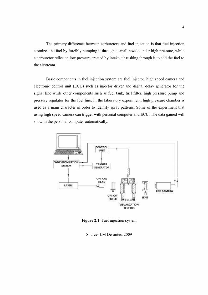
Basic components in fuel injection system are fuel injector, high speed camera and
electronic control unit (ECU) such as injector driver and digital delay generator for the
signal line while other components such as fuel tank, fuel filter, high pressure pump and
pressure regulator for the fuel line. In the laboratory experiment, high pressure chamber is
used as a main character in order to identify spray patterns. Some of the experiment that
using high speed camera can trigger with personal computer and ECU. The data gained will
show in the personal computer automatically.
Figure 2.1: Fuel injection system
Source: J.M Desantes, 2009
5
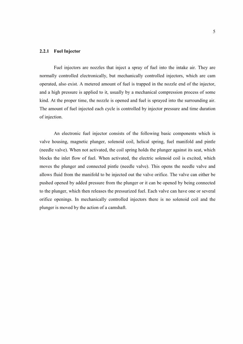
2.2.1 Fuel Injector
Fuel injectors are nozzles that inject a spray of fuel into the intake air. They are
normally controlled electronically, but mechanically controlled injectors, which are cam
operated, also exist. A metered amount of fuel is trapped in the nozzle end of the injector,
and a high pressure is applied to it, usually by a mechanical compression process of some
kind. At the proper time, the nozzle is opened and fuel is sprayed into the surrounding air.
The amount of fuel injected each cycle is controlled by injector pressure and time duration
of injection.
An electronic fuel injector consists of the following basic components which is
valve housing, magnetic plunger, solenoid coil, helical spring, fuel manifold and pintle
(needle valve). When not activated, the coil spring holds the plunger against its seat, which
blocks the inlet flow of fuel. When activated, the electric solenoid coil is excited, which
moves the plunger and connected pintle (needle valve). This opens the needle valve and
allows fluid from the manifold to be injected out the valve orifice. The valve can either be
pushed opened by added pressure from the plunger or it can be opened by being connected
to the plunger, which then releases the pressurized fuel. Each valve can have one or several
orifice openings. In mechanically controlled injectors there is no solenoid coil and the
plunger is moved by the action of a camshaft.
6
Figure 2.2 : Fuel Injector
Source: Lee, C.S 2009
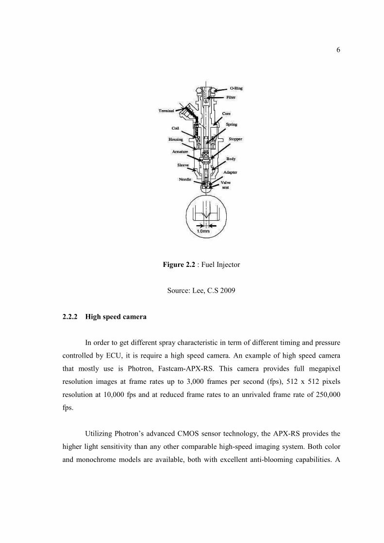
2.2.2 High speed camera
In order to get different spray characteristic in term of different timing and pressure
controlled by ECU, it is require a high speed camera. An example of high speed camera
that mostly use is Photron, Fastcam-APX-RS. This camera provides full megapixel
resolution images at frame rates up to 3,000 frames per second (fps), 512 x 512 pixels
resolution at 10,000 fps and at reduced frame rates to an unrivaled frame rate of 250,000
fps.
Utilizing Photron’s advanced CMOS sensor technology, the APX-RS provides the
higher light sensitivity than any other comparable high-speed imaging system. Both color
and monochrome models are available, both with excellent anti-blooming capabilities. A
7
user selectable ‘Region of Interest’ function enables the active image area to be defined in
steps of 128 pixels wide by 16 pixels high to allow the most efficient use of frame rate,
image resolution and memory capacity for any event. Up to 20 commonly used
configurations can be saved to memory for future operation. Available with Gigabit
Ethernet, Fire wire and fiber optic communications, this compact camera can provide
exposure durations as short as 2 microseconds and is easily operated in the field with or
without a computer through use of the supplied remote keypad, enabling full camera setup,
operation and image replay.
Figure 2.3: High speed camera
Source: Photron 2010
2.2.3 Injector driver
Injector driver modules work with the central computer system and the fuel
injection system in a vehicle. Only vehicles with fuel-injection systems will use an injector
driver module. Engines that need high pressure fuel injection rely on injector driver to
control the fuel injection system. The main purpose of an injector driver is to control the
amount and timing of fuel injection within the vehicle's system.

8
Fig 2.4 : Injector Driver
Source: www.thunderracing.com
2.2.4 Digital delay generator
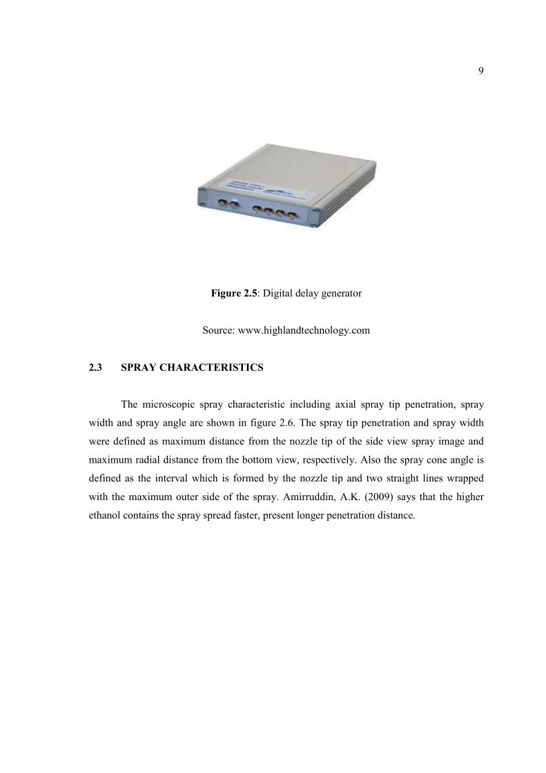
Digital delay generator is a piece of electronic test equipment that provides precise
delays for triggering, syncing, delaying and gating events. It is used in many types of
experiments, controls and processes where electronic timing of a single event or multiple
events to a common timing reference is needed. Similar to a pulse generator in function but
with a digital delay generator the timing resolution is much finer and the delay and width
jitter much less.
9
Figure 2.5: Digital delay generator
Source: www.highlandtechnology.com
2.3 SPRAY CHARACTERISTICS
The microscopic spray characteristic including axial spray tip penetration, spray
width and spray angle are shown in figure 2.6. The spray tip penetration and spray width
were defined as maximum distance from the nozzle tip of the side view spray image and
maximum radial distance from the bottom view, respectively. Also the spray cone angle is
defined as the interval which is formed by the nozzle tip and two straight lines wrapped
with the maximum outer side of the spray. Amirruddin, A.K. (2009) says that the higher
ethanol contains the spray spread faster, present longer penetration distance.
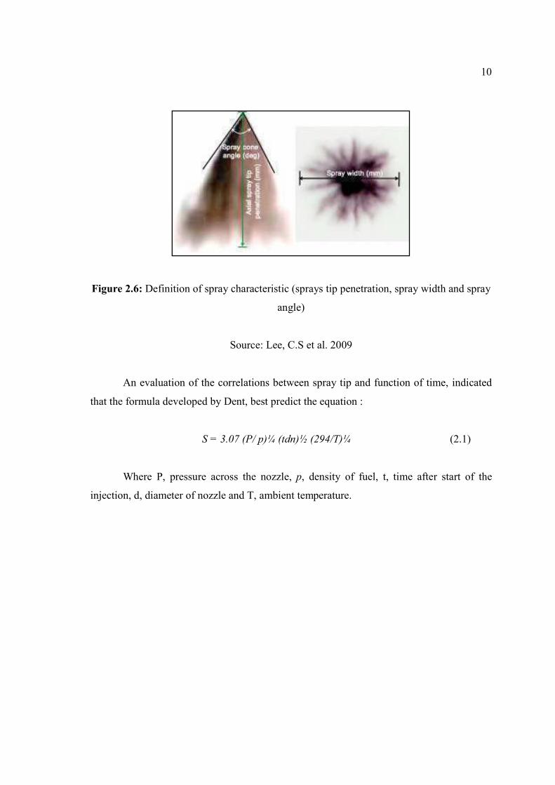
10
Figure 2.6: Definition of spray characteristic (sprays tip penetration, spray width and spray
angle)
Source: Lee, C.S et al. 2009
An evaluation of the correlations between spray tip and function of time, indicated
that the formula developed by Dent, best predict the equation :
S = 3.07 (P/ p)¼ (tdn)½ (294/T)¼ (2.1)
Where P, pressure across the nozzle, p, density of fuel, t, time after start of the
injection, d, diameter of nozzle and T, ambient temperature.

11
2.4 CIRCUIT 555 TIMER IC
The 555 Timer IC is an integrated circuit (chip) implementing a variety of timer
and multivibrator applications. The IC was designed by Hans R. Camenzind in 1970 and
brought to market in 1971 by Signetics (later acquired by Philips). The original name was
the SE555 (metal can)/NE555 (plastic DIP) and the part was described as "The IC Time
Machine". It has been claimed that the 555 gets its name from the three 5 kΩ resistors used
in typical early implementations, but Hans Camenzind has stated that the number was
arbitrary.
Figure 2.7: NE 555 IC
Source: Lubkin, Gloria B., Power Applications of High-Temperature Superconductors,
Physics Today 49, March 1996.