Embed Size (px)
Citation preview
JOHNS HOPKINS APL TECHNICAL DIGEST, VOLUME 29, NUMBER 3 (2010) 289
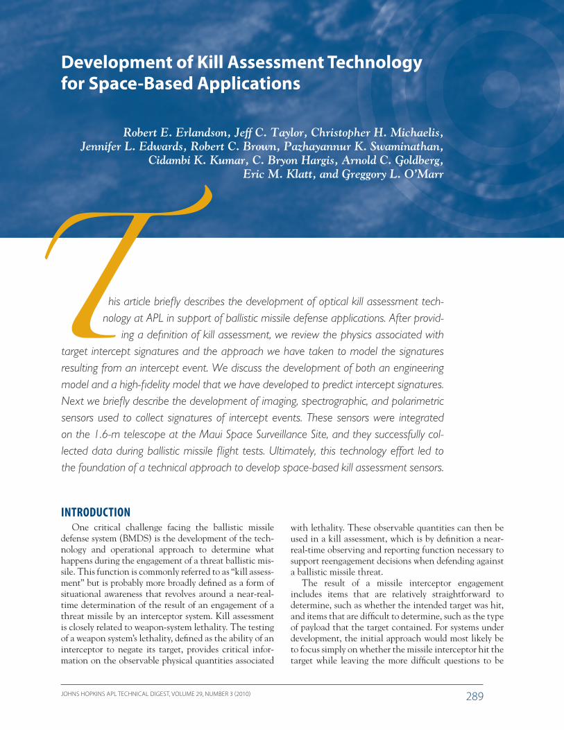
his article briefly describes the development of optical kill assessment tech-nology at APL in support of ballistic missile defense applications. After provid-
ing a definition of kill assessment, we review the physics associated with target intercept signatures and the approach we have taken to model the signatures resulting from an intercept event. We discuss the development of both an engineering model and a high-fidelity model that we have developed to predict intercept signatures. Next we briefly describe the development of imaging, spectrographic, and polarimetric sensors used to collect signatures of intercept events. These sensors were integrated on the 1.6-m telescope at the Maui Space Surveillance Site, and they successfully col-lected data during ballistic missile flight tests. Ultimately, this technology effort led to the foundation of a technical approach to develop space-based kill assessment sensors.
Development of Kill Assessment Technology for Space-Based Applications
Robert E. Erlandson, Jeff C. Taylor, Christopher H. Michaelis, Jennifer L. Edwards, Robert C. Brown, Pazhayannur K. Swaminathan,
Cidambi K. Kumar, C. Bryon Hargis, Arnold C. Goldberg, Eric M. Klatt, and Greggory L. O’Marr
INTRODUCTIONOne critical challenge facing the ballistic missile
defense system (BMDS) is the development of the tech-nology and operational approach to determine what happens during the engagement of a threat ballistic mis-sile. This function is commonly referred to as “kill assess-ment” but is probably more broadly defined as a form of situational awareness that revolves around a near-real-time determination of the result of an engagement of a threat missile by an interceptor system. Kill assessment is closely related to weapon-system lethality. The testing of a weapon system’s lethality, defined as the ability of an interceptor to negate its target, provides critical infor-mation on the observable physical quantities associated
with lethality. These observable quantities can then be used in a kill assessment, which is by definition a near-real-time observing and reporting function necessary to support reengagement decisions when defending against a ballistic missile threat.
The result of a missile interceptor engagement includes items that are relatively straightforward to determine, such as whether the intended target was hit, and items that are difficult to determine, such as the type of payload that the target contained. For systems under development, the initial approach would most likely be to focus simply on whether the missile interceptor hit the target while leaving the more difficult questions to be
JOHNS HOPKINS APL TECHNICAL DIGEST, VOLUME 29, NUMBER 3 (2010)290
R. E. ERLANDSON et al.
addressed by future studies. Focusing solely on whether a hit was achieved is a logical objective for an intercep-tor system that has the objective of hitting targets but is unacceptable from a systems engineering perspective. For the BMDS to truly act as a system, information must be passed from one layer to the next. This is precisely the role of the kill assessment function: to make criti-cal information on a missile engagement available to the battle manager in a timely manner to support the next possible engagement of the threat missile.
APL has recognized the importance of kill assess-ment and that significant technical challenges must be overcome before this function can be implemented as part of the BMDS. Initial efforts to address technol-ogy areas associated with kill assessment were fortu-itously developed during the Active Plasma Experiment rocket experiments involving detonations of shaped-charge devices in the ionosphere.1 APL developed a payload known as the Optical Sensor Payload to col-lect high-speed spectral and radiometric data on the shaped-charge detonation.2 This sensor payload would subsequently serve as the basis of a series of target instru-mentation flown on flight tests. In addition, the Optical Sensor Payload spectral instrument and an Independent Research and Development (IR&D) project would serve as the basis for an APL ground/airborne sensor known as the High Speed Spectrograph (HSS). These efforts in turn led to a major role for APL in support of the Missile Defense Agency’s (MDA) Kill Assessment Technology Program, an ongoing effort begun in 2001 to develop critical kill assessment technologies.
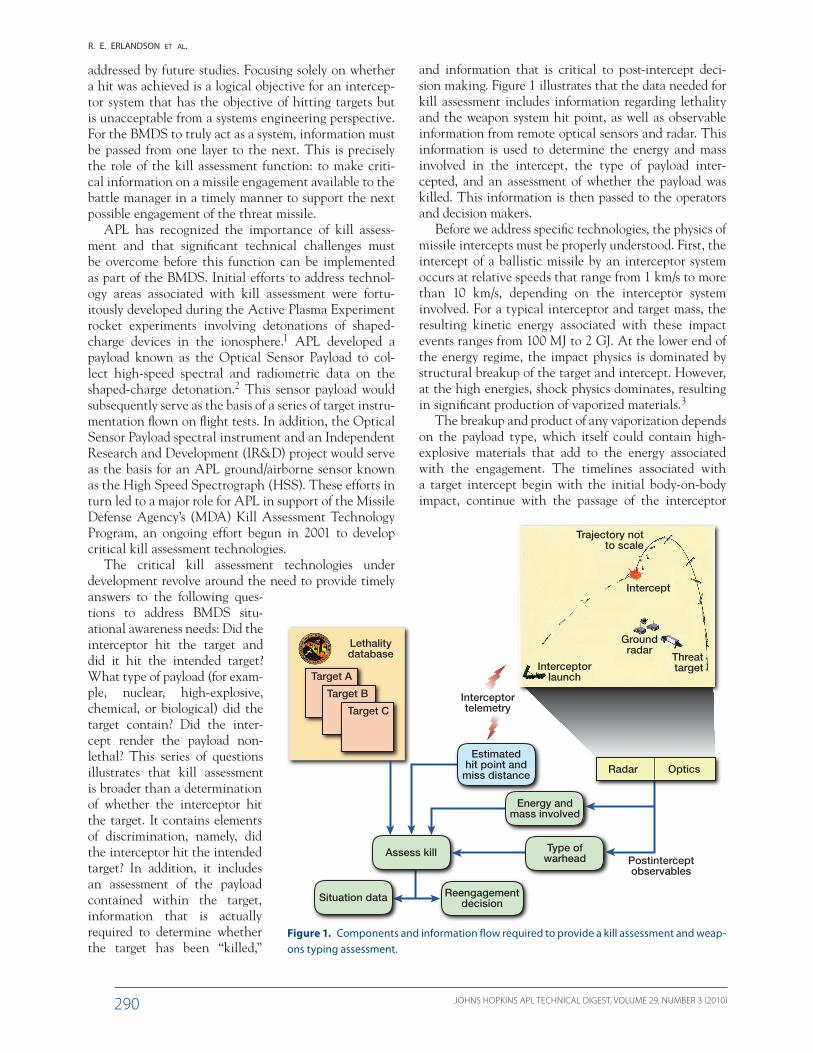
The critical kill assessment technologies under development revolve around the need to provide timely answers to the following ques-tions to address BMDS situ-ational awareness needs: Did the interceptor hit the target and did it hit the intended target? What type of payload (for exam-ple, nuclear, high-explosive, chemical, or biological) did the target contain? Did the inter-cept render the payload non-lethal? This series of questions illustrates that kill assessment is broader than a determination of whether the interceptor hit the target. It contains elements of discrimination, namely, did the interceptor hit the intended target? In addition, it includes an assessment of the payload contained within the target, information that is actually required to determine whether the target has been “killed,”
and information that is critical to post-intercept deci-sion making. Figure 1 illustrates that the data needed for kill assessment includes information regarding lethality and the weapon system hit point, as well as observable information from remote optical sensors and radar. This information is used to determine the energy and mass involved in the intercept, the type of payload inter-cepted, and an assessment of whether the payload was killed. This information is then passed to the operators and decision makers.
Before we address specific technologies, the physics of missile intercepts must be properly understood. First, the intercept of a ballistic missile by an interceptor system occurs at relative speeds that range from 1 km/s to more than 10 km/s, depending on the interceptor system involved. For a typical interceptor and target mass, the resulting kinetic energy associated with these impact events ranges from 100 MJ to 2 GJ. At the lower end of the energy regime, the impact physics is dominated by structural breakup of the target and intercept. However, at the high energies, shock physics dominates, resulting in significant production of vaporized materials.3
The breakup and product of any vaporization depends on the payload type, which itself could contain high-explosive materials that add to the energy associated with the engagement. The timelines associated with a target intercept begin with the initial body-on-body impact, continue with the passage of the interceptor
Estimatedhit point and
miss distance
Energy andmass involved
Type ofwarhead Postintercept
observables
Interceptortelemetry
Lethalitydatabase
Assess kill
Target A
Target B
Target C
Intercept
Trajectory notto scale
Interceptorlaunch
Threattarget
Groundradar
Situation data Reengagementdecision
Radar Optics
Figure 1. Components and information flow required to provide a kill assessment and weap-ons typing assessment.
JOHNS HOPKINS APL TECHNICAL DIGEST, VOLUME 29, NUMBER 3 (2010) 291
KILL ASSESSMENT TECHNOLOGY FOR SPACE-BASED APPLICATIONS
through the target (typically lasting hundreds of micro-seconds), followed by the material response phase, debris (gaseous, plasma, particulates, and fragments) expan-sion, and debris–atmosphere interaction.
The developmental items necessary to implement a kill assessment system include the following:
• Physics-based models of the interceptor event• High-speed sensors to record the signatures of target
intercepts on relevant timescales associated with the interceptor event
• Identification of sensors within the BMDS archi-tecture that can provide relevant kill assessment information
• New sensor technologies that can enhance existing BMDS kill-assessment-related sensors
• Algorithms to provide assessment of target kill and identify the payload type
The two items that we discuss in this article are the devel-opment of physics-based models and high-speed sensors.
PHYSICS-BASED MODELING OF TARGET INTERCEPT SIGNATURES
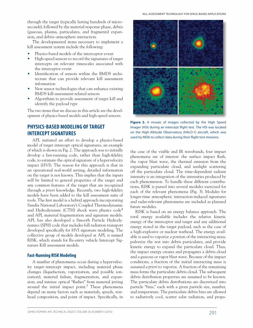
APL initiated an effort to develop a physics-based model of target intercept optical signatures, an example of which is shown in Fig. 2. The approach was to initially develop a fast-running code, rather than high-fidelity code, to estimate the optical signature of a hypervelocity impact (HVI). The reason for this approach is that in an operational real-world setting, detailed information on the target is not known. This implies that the inputs will be limited to general properties of the target and any common features of the target that are recognized through a priori knowledge. Recently, two high-fidelity models have been added to the kill assessment suite of tools. The first model is a hybrid approach incorporating Sandia National Laboratory’s Coupled Thermodynamic and Hydrodynamic (CTH) shock wave physics code4 and APL material fragmentation and signature models. APL has also developed a Smooth Particle Hydrody-namics (SPH) code that includes full radiation transport developed specifically for HVI signature modeling. The collective group of models developed at APL is named RISK, which stands for Re-entry vehicle Intercept Sig-nature Kill assessment models.
Fast-Running RISK ModelingA number of phenomena occur during a hyperveloc-
ity target–intercept impact, including material phase changes (liquefaction, vaporization, and possible ion-ization); material failure, fragmentation, and expan-sion; and intense optical “flashes” from material jetting around the initial impact point.5 These phenomena depend on many factors such as materials, speeds, war-head composition, and point of impact. Specifically, in
Figure 2. A mosaic of images collected by the High Speed Imager (HSI) during an intercept flight test. The HSI was located on the High-Altitude Observatory (HALO-1) aircraft, which was used by MDA to collect data during their flight test missions.
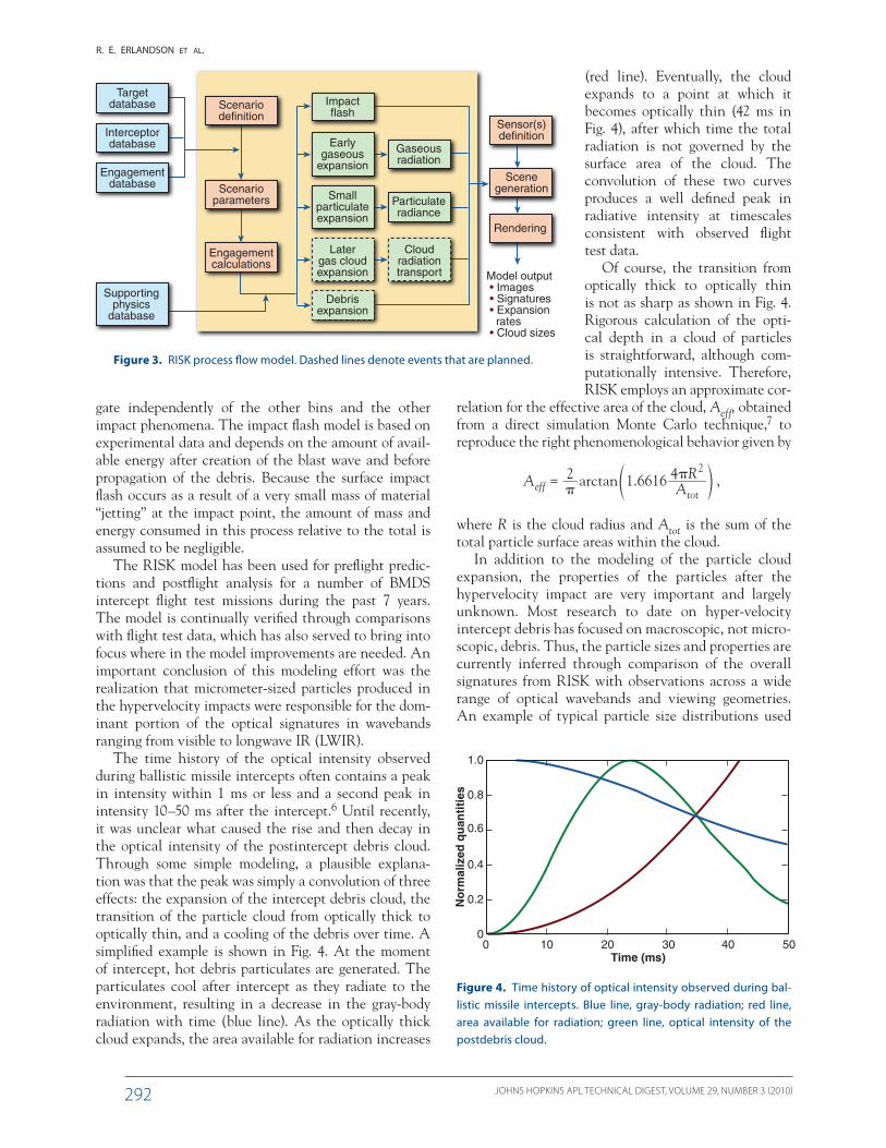
the case of the visible and IR wavebands, four impact phenomena are of interest: the surface impact flash, the vapor blast wave, the thermal emission from the expanding particulate cloud, and sunlight scattering off the particulate cloud. The time-dependent radiant intensity is an integration of the intensities produced by each phenomenon. To handle these different contribu-tions, RISK is parsed into several modules exercised for each of the relevant phenomena (Fig. 3). Modules for longer-time atmospheric interaction-induced signatures and radar-relevant phenomena are included as planned future modules.
RISK is based on an energy balance approach. The total energy available includes the relative kinetic energy of the interceptor and target and any additional energy stored in the target payload, such as the case of a high-explosive or nuclear warhead. The energy avail-able is used to vaporize a portion of the interacting mass, pulverize the rest into debris particulates, and provide kinetic energy to expand the particulate cloud. Thus, the impact energy creates and propagates a debris cloud and a gaseous or vapor blast wave. Because of the impact conditions, a fraction of the initial interacting mass is assumed a priori to vaporize. A fraction of the remaining mass forms the particulate debris cloud. The subsequent debris distribution properties are assumed to be known. The particulate debris distributions are discretized into particle “bins,” each with a given particle size, number, and temperature. The particulate debris bins are allowed to radiatively cool, scatter solar radiation, and propa-
JOHNS HOPKINS APL TECHNICAL DIGEST, VOLUME 29, NUMBER 3 (2010)292
R. E. ERLANDSON et al.
Figure 3. RISK process flow model. Dashed lines denote events that are planned.
Smallparticulateexpansion
Earlygaseous
expansion
Latergas cloudexpansion
Supportingphysics
database
Cloudradiationtransport
Debrisexpansion
Particulateradiance
Engagementcalculations
Engagementdatabase
Interceptordatabase
Targetdatabase
Scenarioparameters
Scenariodefinition
Scenegeneration
Sensor(s)definition
Rendering
Gaseousradiation
Impactflash
Model output • Images • Signatures • Expansion rates • Cloud sizes
gate independently of the other bins and the other impact phenomena. The impact flash model is based on experimental data and depends on the amount of avail-able energy after creation of the blast wave and before propagation of the debris. Because the surface impact flash occurs as a result of a very small mass of material “jetting” at the impact point, the amount of mass and energy consumed in this process relative to the total is assumed to be negligible.
The RISK model has been used for preflight predic-tions and postflight analysis for a number of BMDS intercept flight test missions during the past 7 years. The model is continually verified through comparisons with flight test data, which has also served to bring into focus where in the model improvements are needed. An important conclusion of this modeling effort was the realization that micrometer-sized particles produced in the hypervelocity impacts were responsible for the dom-inant portion of the optical signatures in wavebands ranging from visible to longwave IR (LWIR).
The time history of the optical intensity observed during ballistic missile intercepts often contains a peak in intensity within 1 ms or less and a second peak in intensity 10–50 ms after the intercept.6 Until recently, it was unclear what caused the rise and then decay in the optical intensity of the postintercept debris cloud. Through some simple modeling, a plausible explana-tion was that the peak was simply a convolution of three effects: the expansion of the intercept debris cloud, the transition of the particle cloud from optically thick to optically thin, and a cooling of the debris over time. A simplified example is shown in Fig. 4. At the moment of intercept, hot debris particulates are generated. The particulates cool after intercept as they radiate to the environment, resulting in a decrease in the gray-body radiation with time (blue line). As the optically thick cloud expands, the area available for radiation increases
(red line). Eventually, the cloud expands to a point at which it becomes optically thin (42 ms in Fig. 4), after which time the total radiation is not governed by the surface area of the cloud. The convolution of these two curves produces a well defined peak in radiative intensity at timescales consistent with observed flight test data.
Of course, the transition from optically thick to optically thin is not as sharp as shown in Fig. 4. Rigorous calculation of the opti-cal depth in a cloud of particles is straightforward, although com-putationally intensive. Therefore, RISK employs an approximate cor-
relation for the effective area of the cloud, Aeff, obtained from a direct simulation Monte Carlo technique,7 to reproduce the right phenomenological behavior given by
. ,arctanA AR2 1 6616 4
efftot
2
��= e o
where R is the cloud radius and Atot is the sum of the total particle surface areas within the cloud.
In addition to the modeling of the particle cloud expansion, the properties of the particles after the hypervelocity impact are very important and largely unknown. Most research to date on hyper-velocity intercept debris has focused on macroscopic, not micro-scopic, debris. Thus, the particle sizes and properties are currently inferred through comparison of the overall signatures from RISK with observations across a wide range of optical wavebands and viewing geometries. An example of typical particle size distributions used
Figure 4. Time history of optical intensity observed during bal-listic missile intercepts. Blue line, gray-body radiation; red line, area available for radiation; green line, optical intensity of the postdebris cloud.
50403020Time (ms)
100
1.0
0.8
0.6
0.4
0.2
0
No
rmal
ized
qu
anti
ties
JOHNS HOPKINS APL TECHNICAL DIGEST, VOLUME 29, NUMBER 3 (2010) 293
KILL ASSESSMENT TECHNOLOGY FOR SPACE-BASED APPLICATIONS
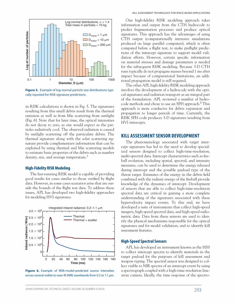
Figure 5. Example of log-normal particle size distributions typi-cally inputted for RISK signature predictions.
100010010Diameter, D (�m)
Lo
g o
f n
um
ber
of
par
ticl
es
1
Log-normal distributions, � = 1.4Total mass in particles = 10 kg
0.1
Dmean = 1 �m
Dmean = 10 �m
Dmean = 200 �m
Figure 6. Example of RISK-model-predicted source intensities across several visible to near-IR (NIR) wavebands from 0.2 to 1.1 µm.
180160140120100Time (ms)
Integrated inband radiance: 0.2–1.1 �m
806040
ThermalThermal + scatter
200
3.0 � 105
2.5 � 105
2.0 � 105
1.5 � 105
1.0 � 105
0.5 � 105
0
Inb
and
rad
ian
ce (
W/s
r)
One high-fidelity RISK modeling approach takes information and output from the CTH hydrocode to predict fragmentation processes and produce optical signatures. This approach has the advantages of using CTH output (computationally intensive simulations produced on large parallel computers), which is often computed before a flight test, to make preflight predic-tions of the intercept signature to support model vali-dation efforts. However, certain specific information on material stresses and damage parameters is needed for the subsequent RISK modeling. Because 3-D CTH runs typically do not propagate masses beyond 1 ms after impact because of computational limitations, an addi-tional propagation model is still required.
The other APL high-fidelity RISK modeling approach involves the development of a hydrocode with the opti-cal signatures and radiation transport as an integral part of the formulation. APL reviewed a number of hydro-code methods and chose to use an SPH approach.8 This approach is more conducive for debris expansion and propagation to longer periods of time. Currently, the RISK SPH code produces 3-D signatures resulting from HVI intercepts.
KILL ASSESSMENT SENSOR DEVELOPMENTThe phenomenology associated with target inter-
cept signatures has led to the need to develop special-ized sensors designed to collect high-time-resolution, multi-spectral data. Intercept characteristics such as fire-ball evolution, including spatial, spectral, and intensity measures, can be used to determine the energy released during intercept and the possible payload type of the threat target. Estimates of the energy in the debris field combined with the radiant energy of the fireball provide knowledge of the dynamics of intercept. Development of sensors that are able to collect high-time-resolution spectral data are critical in gaining a more complete understanding of the signatures associated with these hypervelocity impact events. To this end, we have developed a suite of instruments that collect high-speed imagery, high-speed spectral data, and high-speed radio-metric data. Data from these sensors are used to iden-tify the physical mechanisms responsible for the optical signatures and for model validation, and to identify kill assessment features.
High-Speed Spectral SensorsAPL has developed an instrument known as the HSS
to collect intercept spectra to identify materials in the target payload for the purposes of kill assessment and weapon typing. The spectral sensor was designed to col-lect visible to NIR spectra of an intercept event by using a spectrograph coupled with a high-time-resolution line-array camera. Ideally, the time response of the spectro-
in RISK calculations is shown in Fig. 5. The signatures resulting from this small debris result from the thermal emission as well as from Mie scattering from sunlight (Fig. 6). Note that for later time, the optical intensities do not decay to zero, as one would expect as the par-ticles radiatively cool. The observed radiation is caused by sunlight scattering off the particulate debris. The thermal signature along with the solar scattering sig-nature provide complementary information that can be exploited by using thermal and Mie scattering models to estimate basic properties of the debris such as number density, size, and average temperature.3
High-Fidelity RISK ModelingThe fast-running RISK model is capable of providing
good results for cases similar to those verified by flight data. However, in some cases scenarios arise that are out-side the bounds of the flight test data. To address these issues, APL has developed two high-fidelity approaches for modeling HVI signatures.
JOHNS HOPKINS APL TECHNICAL DIGEST, VOLUME 29, NUMBER 3 (2010)294
R. E. ERLANDSON et al.
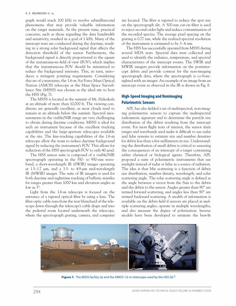
graph would reach 100 kHz to resolve submillisecond phenomena that may provide valuable information on the target materials. At the present time, practical concerns, such as those regarding the data bandwidth and sensitivity, resulted in a goal of 1 kHz. Many of the intercept tests are conducted during the daytime, result-ing in a strong solar background signal that affects the detection threshold of the sensor. Furthermore, the background signal is directly proportional to the square of the instantaneous field of view (FOV), which implies that the instantaneous FOV should be minimized to reduce the background intensity. This, in turn, intro-duces a stringent pointing requirement. Considering this set of constraints, the 1.6-m Air Force Maui Optical Station (AMOS) telescope at the Maui Space Surveil-lance Site (MSSS) was chosen as the ideal site to host the HSS (Fig. 7).
The MSSS is located at the summit of Mt. Haleakala at an altitude of more than 10,000 ft. The viewing con-ditions are generally excellent, as most clouds tend to remain at an altitude below the summit. Spectral mea-surements in the visible/NIR range are very challenging to obtain during daytime conditions. MSSS is ideal for such an instrument because of the excellent tracking capabilities and the large-aperture telescopes available at the site. The fine-tracking capabilities of the 1.6-m telescope allow the team to reduce daytime background signal by reducing the instrument’s FOV. This allows for reduction of the HSS spectrograph FOV to only 40 μrad.
The HSS sensor suite is composed of a visible/NIR spectrograph operating in the 550- to 950-nm wave-band, a short-wavelength IR (SWIR) imager operating at 1.5–1.7 μm, and a 3.3- to 4.9-μm mid-wavelength IR (MWIR) imager. The suite of IR imagers is used for both daytime and nighttime tracking of ballistic missiles for ranges greater than 1000 km and elevation angles as low as 3º.
Light from the 1.6-m telescope is focused on the entrance of a tapered optical fiber by using a lens. The fiber-optic cable runs from the rear blanchard of the tele-scope down through the telescope’s cable drape and into the pedestal room located underneath the telescope, where the spectrograph grating, camera, and computer
are located. The fiber is tapered to reduce the spot size on the spectrograph slit. A 500-nm cut-on filter is used to reject second-order light and reduce contamination of the recorded spectra. The average pixel spacing on the grating is 0.77 nm, while the realized spectral resolution of the instrument is estimated to be 3–4 nm.
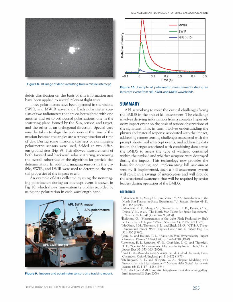
The HSS has successfully operated from MSSS during several MDA tests. Spectral data were collected and used to identify the radiance, temperature, and spectral characteristics of the intercept events. The SWIR and MWIR imagers provide information on the postinter-cept debris and provide context for the non-imaging spectrograph data, where the spectrograph is co-bore-sighted with an imager. An example of an image from an intercept event as observed in the IR is shown in Fig. 8.
High-Speed Imaging and Nonimaging Polarimetric Sensors
APL has also fielded a set of multispectral, non-imag-ing polarimetric sensors to capture the multispectral radiometric signature and to determine the particle size distribution of the debris resulting from the intercept event. For most flight tests of interest, the sensor slant ranges and wavebands used make it difficult to use radar and lidar systems to estimate size and number densities for debris less than a few millimeters in size. Understand-ing the distribution of small debris is critical to assessing the consequences of an intercept of a target containing either chemical or biological agents. Therefore, APL proposed a suite of polarimetric instruments that use sunlight instead of radar or lidar as a source of radiation. The idea is that Mie scattering is a function of debris size distribution, number density, wavelength, and solar scattering angle. The solar scattering angle is defined as the angle between a vector from the Sun to the debris and the debris to the sensor. Angles greater than 90º are termed forward scattering, and angles less than 90º are termed backward scattering. A wealth of information is available on the debris field if sensors are placed at mul-tiple scattering angles, operate in multiple wavelengths, and also measure the degree of polarization. Inverse models have been developed to estimate the best-fit
Figure 7. The MSSS facility (a) and the AMOS 1.6-m telescope used by the HSS (b).9
(a) (b)
JOHNS HOPKINS APL TECHNICAL DIGEST, VOLUME 29, NUMBER 3 (2010) 295
KILL ASSESSMENT TECHNOLOGY FOR SPACE-BASED APPLICATIONS
Figure 8. IR image of debris resulting from a missile intercept.
!
debris distribution on the basis of this information and have been applied to several relevant flight tests.
Three polarimeters have been operated in the visible, SWIR, and MWIR wavebands. Each polarimeter con-sists of two radiometers that are co-boresighted with one another and set to orthogonal polarizations: one in the scattering plane formed by the Sun, sensor, and target, and the other at an orthogonal direction. Special care must be taken to align the polarizers at the time of the mission because the angles are a strong function of time of day. During some missions, two sets of nonimaging polarimetric sensors were used, fielded at two differ-ent ground sites (Fig. 9). This allowed measurements of both forward and backward solar scattering, increasing the overall robustness of the algorithm for particle size determination. In addition, imaging sensors in the vis-ible, SWIR, and LWIR were used to determine the spa-tial properties of the impact event.
An example of data collected by using the nonimag-ing polarimeters during an intercept event is shown in Fig. 10, which shows time–intensity profiles recorded by using one polarization in each wavelength band.
APL polarimetersAPL SWIR imager
APL LWIR imager
Figure 9. Imagers and polarimeter sensors on a tracking mount.
Rel
ativ
e in
tens
ity
–0.1 0 0.1 0.2Time (s)
0.3 0.4 0.5
MWIR
SWIR
NIR (�10)
Figure 10. Example of polarimetric measurements during an intercept event from NIR, SWIR, and MWIR wavebands.
SUMMARYAPL is working to meet the critical challenges facing
the BMDS in the area of kill assessment. The challenge involves deriving information from a complex hypervel-ocity impact event on the basis of remote observations of the signature. This, in turn, involves understanding the physics and material response associated with the impact, addressing remote sensing challenges associated with the prompt short-lived intercept events, and addressing data fusion challenges associated with combining data across the BMDS to assess the type of warhead contained within the payload and whether weapons were destroyed during the impact. This technology now provides the basis for designing and implementing kill assessment sensors. If implemented, such a kill assessment system will result in a savings of interceptors and will provide the situational awareness that will be required by senior leaders during operation of the BMDS.
REFERENCES 1Erlandson, R. E., Meng, C.-I., and Zetzer, Y., “An Introduction to the
North Star Plasma Jet-Space Experiment,” J. Spacecr. Rockets 41(4), 481–482 (2004).
2Erlandson, R. E., Meng, C.-I., Swaminathan, P. K., Kumar, C. K., Dogra, V. K., et al., “The North Star Plasma Jet Space Experiment,” J. Spacecr. Rockets 41(4), 483–489 (2004).
3Eichhorn, G., “Measurements of the Light Flash Produced by High Velocity Particle Impact,” Planet. Space Sci. 23, 1519–1525 (1975).
4McGlaun, J. M., Thomson, S. L., and Elrick, M. G., “CTH: A Three-Dimensional Shock Wave Physics Code,” Int. J. Impact Eng. 10, 351–360 (1990).
5Jean, B., and Rollins, T. L., “Radiation from Hypervelocity Impact Generated Plasma,” AIAA J. 8(10), 1742–1748 (1970).
6Lawrence, R. J., Reinhart, W. D., Chabildas, L. C., and Thornhill, T. F., “Spectral Measurements of Hypervelocity Impact Flash,” Int. J. Impact Eng. 33, 353–363 (2006).
7Bird, G. A., Molecular Gas Dynamics, 1st Ed., Oxford University Press, Clarendon, Oxford, England, pp. 118–127 (1976).
8Stellingwerf, R. F., and Wingate, C. A., “Impact Modeling with Smooth Particle Hydrodynamics,” Memorie della Società Astronomia Italiana 65(4), 1117–1128 (1994).
9U.S. Air Force AMOS website, http://www.maui.afmc.af.mil/gallery.html (accessed 26 Sept 2009).
JOHNS HOPKINS APL TECHNICAL DIGEST, VOLUME 29, NUMBER 3 (2010)296
R. E. ERLANDSON et al.
Robert E. Erlandson is a physicist, a member of the Principal Professional Staff at APL, and Branch Supervisor of the Space Department’s Science and Analysis Branch. He received a Ph.D. in physics from the University of Min-nesota in 1986 and joined APL that same year. Dr. Erlandson has an extensive background in space plasma physics and optical remote sens-ing. He has written more than 80 peer-reviewed publications on topics ranging from auroral physics to active experiments in the ionosphere to wave-particle interactions. Jeff C. Taylor is an aerospace engineer, a member of the Senior Professional Staff at APL, and a Section Super-visor of the Modeling and Signature Phenom-enology Section of the Space Department’s Defense Analyses and Applications Group (SRD). He received a Ph.D. in aerospace engi-
neering from North Carolina State University in 1994 and joined APL shortly thereafter. Dr. Taylor has an extensive background in rarefied gas dynamics and hypersonic aerothermodynamics. During his time at APL, he has worked on many programs focused on ballistic mis-sile defense in areas of midcourse discrimination, plume signatures, kill assessment, lethality, and early launch detection and tracking. Christopher H. Michaelis is an aerospace engineer, a member of the Senior Professional Staff at APL, and Section Supervisor of the Signa-ture Analysis and Data Fusion Section of SRD. He received a Ph.D.
in aeronautics and astronautics from Stanford University in 2001 on the topic of numerical modeling of rarefied flows with thermal and chemical nonequilibrium. During his time at APL, he has worked on missile defense activities, including kill assessment, lethality, and early launch detection and tracking. Jennifer L. Edwards is an aerospace engineer and member of the Senior Professional Staff at APL. She studied aeronautics at the University of Virginia and received her Ph.D. in aerospace engineering from Cornell University, where her research focus was on laser diagnostics of fluid mechanical systems. She joined APL in 2004 as a member of SRD, and she worked on electro-optical sensors for missile defense kill assessment. She is currently working in the Air and Missile Defense Department’s BMD Test and Evaluation Group on various aspects of testing and evaluation, including target development, sensor evaluation, and trajectory analysis. Robert C. Brown is a member of the Principal Professional Staff at APL. He received his Ph.D. in chemical physics from the University of California at Los Angeles in 1983. He has extensive experience in physics-based modeling and numerical simulation for complex dynamical systems. His technical areas of interest have spanned a wide variety of disciplines and include applied research and development in the areas of atmospheric physics, atmospheric dispersion, combustion chemistry, energetic materials, rocket and aircraft exhaust plume chemistry and fluid dynamics, chemical kinetics, spectral signature recognition, and hypervelocity impact. Pazhayannur K. Swaminathan is a member of the Principal Professional Staff at APL in SRD and a research professor at the Whiting School of Engineering on The Johns Hopkins University (JHU) Homewood campus. He received a Ph.D. from JHU in 1980 for his research in theoretical chemical physics and is a theorist with extensive modeling expertise. His career has involved wide application areas such as computational chemistry, atmospheric chemistry/transport modeling, gas/surface chemistry, theory of phase transitions, rocket plume radiation mechanisms, and shock-physics-based problems such as kill assessment signatures and hypervelocity impact damage of spacecraft. His current contributions span multiple APL-business-area projects sponsored by the U.S. Navy, MDA, and NASA as well as collaborative fundamental research with JHU Homewood faculty and students. Cidambi K. Kumar is an astrophysicist by training. He is a senior scientist in SRD. He received his Ph.D. in astronomy from the University of Michigan in 1969. He was on the physics and astronomy faculty of Howard University, Washington, DC, until 2005, when he joined APL. Before that, he consulted on DoD issues (missile defense and space surveillance) for Analytic Services Inc. (ANSER) and APL. He has written more than 30 refereed publications on observational astronomy, laboratory atomic physics, and atmospheric remote sensing. C. Bryon Hargis joined APL in 2002 after graduating with a B.S. in mechanical engineering from Georgia Tech and later earned an M.S. in applied physics from JHU.
The Authors
Jennifer L. Edwards
Jeff C. TaylorRobert E. Erlandson
Robert C. Brown Pazhayannur K.Swaminathan
Christopher H. Michaelis
Cidambi K.Kumar
C. Bryon Hargis
Eric M. KlattArnold C. Goldberg
Greggory L. O’Marr
JOHNS HOPKINS APL TECHNICAL DIGEST, VOLUME 29, NUMBER 3 (2010) 297
KILL ASSESSMENT TECHNOLOGY FOR SPACE-BASED APPLICATIONS
The Johns Hopkins APL Technical Digest can be accessed electronically at www.jhuapl.edu/techdigest.
His technical expertise runs the gamut from optomechanical design to physics-based system analysis to testing and evaluation. He has been the lead engineer for many of the kill assessment sensors built to date such as the entire suite of APL sensors hosted at the AMOS and a sensor that detected the first passive RF intercept signature of a live test using the Very Large Array. In addition, he works part time in the Quantum Optics Laboratory within APL’s Milton Eisenhower Research Center and manages a program sponsored by the Office of Naval Research that seeks to provide accurate missile warning for naval aircraft. Arnold C. Goldberg received his Ph.D. in physics from the University of Mary-land in 1996. He has worked in the field of infrared sensors since 1981, first at the Martin Marietta Laboratories (1981–1995), then at the Army Research Laboratory (1995–2005), before joining the SRD group of the Space Department in December 2005. He has worked on many aspects of infrared materials and devices, including pioneering work in the application of multispectral infrared focal-plane arrays. At APL, he is the Supervisor of the Electro-Optical Sensors Section in SRD, and his main area of research is in the application of LWIR sensors to missile defense and national security space applications. Eric M. Klatt has studied space plasma physics and space technology in an academic and professional capacity for more than 10 years. He completed a Ph.D. in electrical and computer engineering at Cornell University in 2005. His doctoral thesis work involved a multiple-payload sounding-rocket experiment to study auroral physics. He has experience with several sounding-rocket missions from the build phase through data analysis and has been working on remote electro-optical sensing at APL for the last 3 years. Greggory L. O’Marr is an electrical engineer and sensor scientist for SRD. He received his M.S. in electrical engineering from the Pennsylvania State University in 2002 for research in laser remote sensing of airborne particulate matter. He has been the lead engineer for several of SRD’s kill assessment program instruments, including the HSS/HSI and the Intercept Debris Measurement Program’s instrument suite. He has also been the team lead for many of SRD’s field tests. His current work is as Executive Officer for the User Assessment Team under the STACS Program, and he is also developing a new radiometer sensing suite for the AEGIS Program. For further information on the work reported here, contact Robert Erlandson. His e-mail address is [email protected].