Embed Size (px)
Citation preview
21
1. Introduction
The All Wheel Control (AWC) is a MMC’s four-wheeldynamic control philosophy for maximally exploitingthe capability of all four tires of a vehicle in a balancedmanner to realize predictable handling and high marginof performance, which in turn yield the driving pleasureand utmost safety that MMC sees as fundamentals inproducing vehicles.
The Super All Wheel Control (S-AWC) is an integrat-ed vehicle dynamics control system that combines vari-ous components based on the four-wheel drive (4WD)control, and controls all components integrally toembody the AWC philosophy(1).
The S-AWC system on the LANCER EVOLUTION Xdelivers all of the following functions under integratedcontrol: Active Center Differential (ACD)(2), Active YawControl (AYC)(3), Active Stability Control (ASC)(4), andAntilock Brake System (ABS). As shown in Fig. 1, byadding braking control to the ACD-AYC combination,which has superior controllability among the currentlyexisting 4WD systems, the S-AWC can control both thedriving and braking forces and so handle both longitu-dinal and lateral behavior of the vehicle. As a result, theS-AWC seamlessly improves the vehicle’s dynamic per-formance for various vehicle operations such as accel-eration, deceleration and cornering.
This paper introduces the S-AWC system focusingon the integrated driving and braking force controlusing the yaw rate feedback control technology, whichis the most remarkable feature of the system.
2. Consideration and selection of system configuration
2.1 Basic control method
The aim of the S-AWC system is to achieve both pre-dictable handling and high margin of performance.
Predictable handling means changing the vehicledirection faithfully according to the driver’s intentions,in other words, the vehicle exactly follows the driver’ssteering operations. High margin of performance, onthe other hand, means keeping the vehicle directionwithout being affected by disturbances, in other words,restraining vehicle’s behavioral changes that are notcaused by the driver’s steering operations.
Although these two characteristics appear different,they are similar in that they both require the vehicle’sbehavior to match the driver’s steering operation, andcan be achieved simultaneously by minimizing the dif-ference between the target vehicle behavior calculatedfrom the steering wheel angle and the actual vehiclebehavior.
Development of Integrated Vehicle Dynamics Control System ‘S-AWC’
Takami MIURA* Yuichi USHIRODA* Kaoru SAWASE*Naoki TAKAHASHI* Kazufumi HAYASHIKAWA**
AbstractThe Super All Wheel Control (S-AWC) for LANCER EVOLUTION X is an integrated vehicle
dynamics control system for handling the Active Center Differential (ACD), Active Yaw Control
(AYC), Active Stability Control (ASC) and Antilock Brake System (ABS). It is based on the All Wheel
Control (AWC) philosophy advocated by Mitsubishi Motors Corporation (MMC). To ensure pre-
dictable handling and a high performance margin, the S-AWC system calculates the yaw moment
by using the yaw rate feedback control and distributes the yaw moment to each component taking
into consideration its characteristics. S-AWC can improve the vehicle cornering performance seam-
lessly at various driving conditions.
Key words: Four Wheel Drive (4WD), Vehicle Dynamics, Integrated Control
* Drivetrain Engineering Dept., Development Engineering Office ** Chassis Design Dept., Development Engineering Office
Fig. 1 Components of S-AWC
22
Development of Integrated Vehicle Dynamics Control System ‘S-AWC’
To achieve this, the S-AWC system adopts yaw ratefeedback control as basic control method, in which thevehicle behavior (target yaw rate) calculated from suchparameters as the steering wheel angle is comparedwith the actual vehicle behavior (actual yaw rate) givenby the yaw rate sensor to determine the target amountof control to be provided by the system.
2.2 Components
To make the yaw rate feedback control work effec-tively, it is necessary to control the yaw moment actingon the vehicle most appropriately under various drivingconditions.
The types of control that can generate yaw momentinclude the following: the steering angle control work-ing on the steering system; the roll stiffness distributioncontrol working on the suspension system; the longitu-dinal torque distribution control and the lateral torquedifference control working on the drive train; and thelateral braking control. The steering angle control caneffectively generate yaw moment in the linear region ofthe tire characteristics, but it cannot generate sufficientmoment in the nonlinear region of the tire characteris-tics. The roll stiffness distribution control can indirectlycontrol the yaw moment, but its effect is limited to thenonlinear region of the tire characteristics. Similarly,the longitudinal torque distribution control is effectiveonly in the nonlinear region of the tire characteristics.On the other hand, the direct yaw moment control thatuses the difference in driving and braking forcesbetween the left and right wheels can generate yawmoment in both the linear and nonlinear regions of thetire characteristics(5).
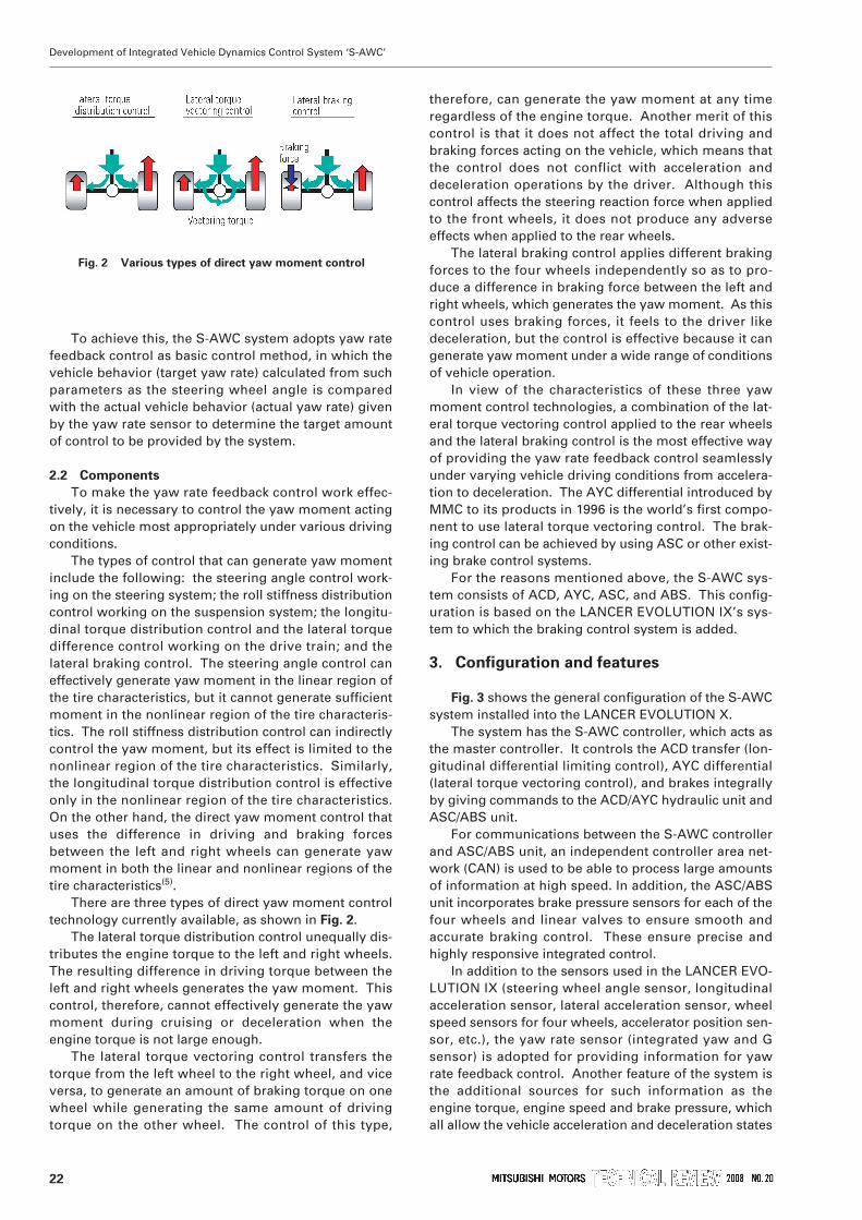
There are three types of direct yaw moment controltechnology currently available, as shown in Fig. 2.
The lateral torque distribution control unequally dis-tributes the engine torque to the left and right wheels.The resulting difference in driving torque between theleft and right wheels generates the yaw moment. Thiscontrol, therefore, cannot effectively generate the yawmoment during cruising or deceleration when theengine torque is not large enough.
The lateral torque vectoring control transfers thetorque from the left wheel to the right wheel, and viceversa, to generate an amount of braking torque on onewheel while generating the same amount of drivingtorque on the other wheel. The control of this type,
therefore, can generate the yaw moment at any timeregardless of the engine torque. Another merit of thiscontrol is that it does not affect the total driving andbraking forces acting on the vehicle, which means thatthe control does not conflict with acceleration anddeceleration operations by the driver. Although thiscontrol affects the steering reaction force when appliedto the front wheels, it does not produce any adverseeffects when applied to the rear wheels.
The lateral braking control applies different brakingforces to the four wheels independently so as to pro-duce a difference in braking force between the left andright wheels, which generates the yaw moment. As thiscontrol uses braking forces, it feels to the driver likedeceleration, but the control is effective because it cangenerate yaw moment under a wide range of conditionsof vehicle operation.
In view of the characteristics of these three yawmoment control technologies, a combination of the lat-eral torque vectoring control applied to the rear wheelsand the lateral braking control is the most effective wayof providing the yaw rate feedback control seamlesslyunder varying vehicle driving conditions from accelera-tion to deceleration. The AYC differential introduced byMMC to its products in 1996 is the world’s first compo-nent to use lateral torque vectoring control. The brak-ing control can be achieved by using ASC or other exist-ing brake control systems.
For the reasons mentioned above, the S-AWC sys-tem consists of ACD, AYC, ASC, and ABS. This config-uration is based on the LANCER EVOLUTION IX’s sys-tem to which the braking control system is added.
3. Configuration and features
Fig. 3 shows the general configuration of the S-AWCsystem installed into the LANCER EVOLUTION X.
The system has the S-AWC controller, which acts asthe master controller. It controls the ACD transfer (lon-gitudinal differential limiting control), AYC differential(lateral torque vectoring control), and brakes integrallyby giving commands to the ACD/AYC hydraulic unit andASC/ABS unit.
For communications between the S-AWC controllerand ASC/ABS unit, an independent controller area net-work (CAN) is used to be able to process large amountsof information at high speed. In addition, the ASC/ABSunit incorporates brake pressure sensors for each of thefour wheels and linear valves to ensure smooth andaccurate braking control. These ensure precise andhighly responsive integrated control.
In addition to the sensors used in the LANCER EVO-LUTION IX (steering wheel angle sensor, longitudinalacceleration sensor, lateral acceleration sensor, wheelspeed sensors for four wheels, accelerator position sen-sor, etc.), the yaw rate sensor (integrated yaw and Gsensor) is adopted for providing information for yawrate feedback control. Another feature of the system isthe additional sources for such information as theengine torque, engine speed and brake pressure, whichall allow the vehicle acceleration and deceleration states
Fig. 2 Various types of direct yaw moment control
23
Development of Integrated Vehicle Dynamics Control System ‘S-AWC’
to be quickly and accurately identified, and thus for thecontrol response to be improved.
4. Outview of system control
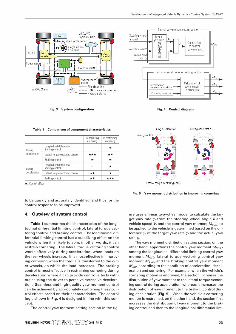
Table 1 summarizes the characteristics of the longi-tudinal differential limiting control, lateral torque vec-toring control, and braking control. The longitudinal dif-ferential limiting control has a stabilizing effect on thevehicle when it is likely to spin, in other words, it canrestrain cornering. The lateral torque vectoring controlworks effectively during acceleration, when loads onthe rear wheels increase. It is most effective in improv-ing cornering when the torque is transferred to the out-er wheels, on which the load increases. The brakingcontrol is most effective in restraining cornering duringdeceleration where it can provide control effects with-out causing the driver to perceive excessive decelera-tion. Seamless and high-quality yaw moment controlcan be achieved by appropriately combining these con-trol effects based on their characteristics. The controllogic shown in Fig. 4 is designed in line with this con-cept.
The control yaw moment setting section in the fig-
ure uses a linear two-wheel model to calculate the tar-get yaw rate γT from the steering wheel angle θ andvehicle speed V, and the control yaw moment MCONT tobe applied to the vehicle is determined based on the dif-ference γE of the target yaw rate γT and the actual yawrate γR.
The yaw moment distribution setting section, on theother hand, apportions the control yaw moment MCONT
among the longitudinal differential limiting control yawmoment MACD, lateral torque vectoring control yawmoment MAYC, and the braking control yaw momentMBRK according to the condition of acceleration, decel-eration and cornering. For example, when the vehicle’scornering motion is improved, the section increases thedistribution of yaw moment to the lateral torque vector-ing control during acceleration, whereas it increases thedistribution of yaw moment to the braking control dur-ing deceleration (Fig. 5). When the vehicle’s corneringmotion is restrained, on the other hand, the section firstincreases the distribution of yaw moment to the brak-ing control and then to the longitudinal differential lim-
Fig. 4 Control diagram
Fig. 5 Yaw moment distribution in improving cornering
Table 1 Comparison of component characteristics
In improving In restrainingcornering cornering
Longitudinal differential – (During limiting controlacceleration Lateral torque vectoring control ((( ((
Braking control ( (
Longitudinal differential – (During limiting controldeceleration Lateral torque vectoring control (( (
Braking control (( (((
(: Control effect
Fig. 3 System configuration
24
Development of Integrated Vehicle Dynamics Control System ‘S-AWC’
iting control.Like this example, the system achieves an integrat-
ed vehicle dynamics control using the yaw rate feed-back by apportioning the yaw moment among the lon-gitudinal differential limiting control, left-right torquevectoring control and the braking control most appro-priately according to the characteristics listed in Table
1.
5. Vehicle performance
This section describes how the S-AWC demon-strates its effect in an actual vehicle using an example.This example compares the dynamics control resultsderived from the tests on the same vehicle when it isequipped with the S-AWC (called “With S-AWC” here-after) and when it is equipped with a control system thatsimulates the LANCER EVOLUTION IX’s system (called“Without S-AWC”).
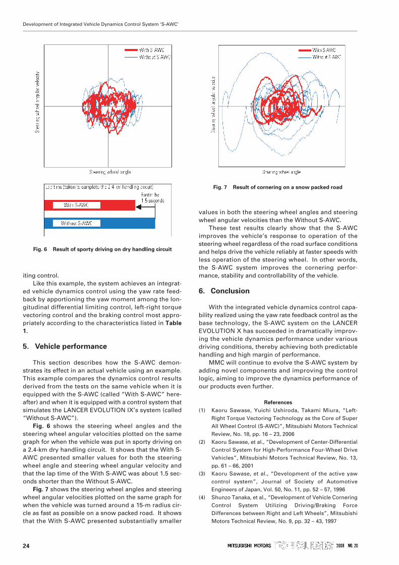
Fig. 6 shows the steering wheel angles and thesteering wheel angular velocities plotted on the samegraph for when the vehicle was put in sporty driving ona 2.4-km dry handling circuit. It shows that the With S-AWC presented smaller values for both the steeringwheel angle and steering wheel angular velocity andthat the lap time of the With S-AWC was about 1.5 sec-onds shorter than the Without S-AWC.
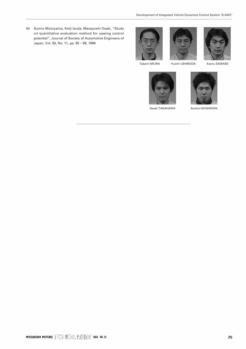
Fig. 7 shows the steering wheel angles and steeringwheel angular velocities plotted on the same graph forwhen the vehicle was turned around a 15-m radius cir-cle as fast as possible on a snow packed road. It showsthat the With S-AWC presented substantially smaller
values in both the steering wheel angles and steeringwheel angular velocities than the Without S-AWC.
These test results clearly show that the S-AWCimproves the vehicle’s response to operation of thesteering wheel regardless of the road surface conditionsand helps drive the vehicle reliably at faster speeds withless operation of the steering wheel. In other words,the S-AWC system improves the cornering perfor-mance, stability and controllability of the vehicle.
6. Conclusion
With the integrated vehicle dynamics control capa-bility realized using the yaw rate feedback control as thebase technology, the S-AWC system on the LANCEREVOLUTION X has succeeded in dramatically improv-ing the vehicle dynamics performance under variousdriving conditions, thereby achieving both predictablehandling and high margin of performance.
MMC will continue to evolve the S-AWC system byadding novel components and improving the controllogic, aiming to improve the dynamics performance ofour products even further.
References
(1) Kaoru Sawase, Yuichi Ushiroda, Takami Miura, “Left-Right Torque Vectoring Technology as the Core of SuperAll Wheel Control (S-AWC)”, Mitsubishi Motors TechnicalReview, No. 18, pp. 16 – 23, 2006
(2) Kaoru Sawase, et al., “Development of Center-DifferentialControl System for High-Performance Four-Wheel DriveVehicles”, Mitsubishi Motors Technical Review, No. 13,pp. 61 – 66, 2001
(3) Kaoru Sawase, et al., “Development of the active yawcontrol system”, Journal of Society of AutomotiveEngineers of Japan, Vol. 50, No. 11, pp. 52 – 57, 1996
(4) Shunzo Tanaka, et al., “Development of Vehicle CorneringControl System Utilizing Driving/Braking ForceDifferences between Right and Left Wheels”, MitsubishiMotors Technical Review, No. 9, pp. 32 – 43, 1997
Fig. 6 Result of sporty driving on dry handling circuit
Fig. 7 Result of cornering on a snow packed road
(5) Sumio Motoyama, Keiji Isoda, Masayoshi Osaki, “Studyon quantitative evaluation method for yawing controlpotential”, Journal of Society of Automotive Engineers ofJapan, Vol. 50, No. 11, pp. 95 – 99, 1996
25
Development of Integrated Vehicle Dynamics Control System ‘S-AWC’
Takami MIURA Yuichi USHIRODA Kaoru SAWASE
Naoki TAKAHASHI Kazufumi HAYASHIKAWA