Embed Size (px)
Citation preview
Research Report
http://www.tytlabs.com/review/© Toyota Central R&D Labs., Inc. 2014
11R&D Review of Toyota CRDL, Vol.45 No.2 (2014) 11-19
Yutaka Nonomura, Motohiro Fujiyoshi and Hisayoshi Sugihara
Inertial Force, Posture Angles, Angular Rate Sensor, Acceleration Sensor, MEMS (Micro Electro Mechanical Systems) , Partner Robot, Human Support Robot, WORLD EXPO, Biped-type Robot, Rolling-type Robot
Report received on May 12, 2014
Development of Inertial Force Sensing System for Control of Partner Robot
Special Feature: Sensors
An inertial force sensing system for control of a partner robot was developed. We named this system MOST (MOtion Sensing Technology). MOST provides a set of the true posture angles of the robot. MOST consists of three angular rate sensors, three acceleration sensors, and a digital signal processor (DSP). The acceleration sensor is a semiconductor type detecting the mass displacement due to acceleration by the capacitance change. The angular rate sensor is a quartz type detecting a vibration change due to the Coriolis force by the charge change. The sensors are made by micro electro mechanical system (MEMS) technology and are used for automotive control in mass-produced automobiles. The set of posture angles is generally obtained by integrating angular rates over time. However, the posture angles diverge due to offset output integration. A new algorithm is proposed to suppress the divergence of the posture angles with the DSP in real time. The size and weight of MOST were 200 cm3 and 320 g, respectively. The accuracy of the posture angle was +/– 0.017 rad (+/– 1 deg). The sensing units enabled miniaturization and high reliability sufficient to meet long-term stability for the partner robot. Partner robots worked well for six months at the WORLD EXPO 2005 in Aichi, Japan. The highly reliable performance at the exhibition demonstrated that MOST is useful for posture-angle control of next-generation robots.
1. Introduction
The demands are many for robots throughout the world. In the production plants of automobile and electronics products, many kinds of robots are used for welding, painting, assembling, etc. At the present, the main usages of the robots are in the plants. They work in harsh environments in place of the workers and are completely isolated from these workers. In the plant, most automation robots are fixed on floors and the working areas are limited.
Another type of conventional robot is the rolling-type robot that has three, four, or six wheels. The bodies of conventional rolling robots are stable and move on the floor. They carry parts and assemblies of automobile and electronics products in the plant, but they cannot easily move fast and turn quickly on the floor.
People have high expectations for next-generation robots. They will be useful for nursing care, domestic help, office help, and personal assistance. They should be able to work with people and make contact
with them as human support robots. Therefore, an autonomous control with a sensing system of their postures, a detecting system for objects and persons, and an evasive action system from the objects and persons are important for human support robots. Human support robots are free from anchors on the floor and move around people. That is one of the most important differences between conventional robots and next-generation ones.
Two types of robots, a biped-type and a rolling-type robot with two wheels, are representative of the next-generation robots, which work and move on the floor on feet or wheels. The biped-type robot can walk like a human with its legs and feet. The rolling-type robot has only two wheels, so it can turn quickly like a spindle and can run fast. The rolling-type robot with two wheels is an inverted pendulum type robot. The robot should be controlled to keep its balance in both stable and moving states. For the biped-type and the rolling-type robots with two wheels, detection of their posture or posture angles is

12
© Toyota Central R&D Labs., Inc. 2014 http://www.tytlabs.com/review/
R&D Review of Toyota CRDL, Vol.45 No.2 (2014) 11-19
one of the required technologies. The robots can keep their postures and walk or run with their legs or wheels by using their posture or posture angle signals.
On the other hand, in the body control of humans, three semicircular canals are used to keep the body in good balance when a human stands up and walks with his legs or rides on wheels. If we can make an artificial semicircular canal and install it in the robots, the robots can stand up, walk and ride as a human does, as shown in Fig. 1. The biped-type robot can walk with its legs and feet as a human does when he walks with stilts, as shown on the left side of Fig. 1. The rolling-type robot can move as a human does when he rides a unicycle, as shown on the right side of Fig. 1. The three semicircular canals detect the angular rates of a human head and body. Gyro (angular rate) sensors also detect the angular rate in an artificial manner. Therefore, gyro sensors play a main role in the artificial semicircular canal, which is well known as an inertial sensing system.
“Partner robot” is our name for one of the human support robots. Typical applications of the partner robot are assistance for people, carrying goods and people, and personal mobility. The partner robot should walk and move freely around people and make contact with them to serve them. The partner robot can walk and move by using the inertial sensing system. However, no inertial sensing system is compact enough to be installed in the partner robots. We developed a new compact sensing system, called MOST (MOtion Sensing Technology), which works as the artificial semicircular canal in the partner robots. To make the artificial semicircular canal for the partner robots, the selection of the sensors such as an accelerometer and angular rate sensors is very important. As the sensors have to have a high degree of precision and be small
and reliable, the sensors for automobiles were selected. A new algorithm was developed to obtain a set of true posture angles in real time. This paper describes the sensors, the new algorithm, and MOST system to control the partner robot.
2. Theory
2. 1 Posture Angles
The posture angles of robots can be expressed in several ways. We use roll, pitch, and yaw systems with symbols y, q, and f. The standard coordinates of X, Y, and Z and the definitions of roll, pitch, and yaw are shown in Fig. 2. A posture matrix T(n) is expressed in Eq. (1). Rotation matrices for the roll, pitch, and yaw systems are described in Eqs. (2) to (4).
Fig. 1 Role of the artificial three semicircular canal.
WALK ON STILTS RIDE A UNICYCLE
WALK WITH KEEPING BALANCE MOVE WITH KEEPING BALANCE
ARTIFICIAL THREE SEMICIRCULAR CANAL
GYRO SENSOR
BIPED-TYPE ROBOT ROLLING TYPE ROBOT
Fig. 2 Definition of roll, pitch, and yaw system.
(3)
(2)
(4)
(1)
=
1000000
)(ifchebgda
nT
13
© Toyota Central R&D Labs., Inc. 2014 http://www.tytlabs.com/review/
R&D Review of Toyota CRDL, Vol.45 No.2 (2014) 11-19
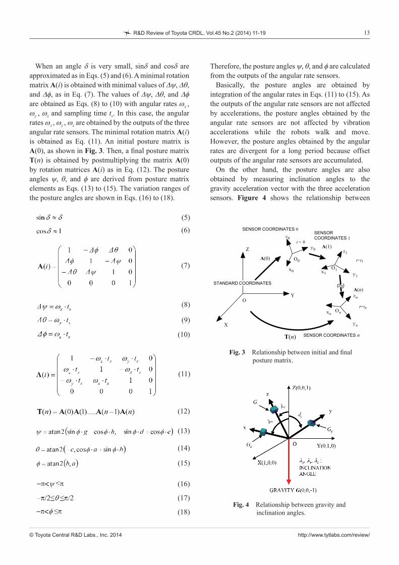
When an angle d is very small, sind and cosd are approximated as in Eqs. (5) and (6). A minimal rotation matrix A(i) is obtained with minimal values of Dy, Dq, and Df, as in Eq. (7). The values of Dy, Dq, and Df are obtained as Eqs. (8) to (10) with angular rates wx , wy , wz and sampling time ts. In this case, the angular rates wx , wy , wz are obtained by the outputs of the three angular rate sensors. The minimal rotation matrix A(i) is obtained as Eq. (11). An initial posture matrix is A(0), as shown in Fig. 3. Then, a final posture matrix T(n) is obtained by postmultiplying the matrix A(0) by rotation matrices A(i) as in Eq. (12). The posture angles y, q, and f are derived from posture matrix elements as Eqs. (13) to (15). The variation ranges of the posture angles are shown in Eqs. (16) to (18).
Therefore, the posture angles y, q, and f are calculated from the outputs of the angular rate sensors.
Basically, the posture angles are obtained by integration of the angular rates in Eqs. (11) to (15). As the outputs of the angular rate sensors are not affected by accelerations, the posture angles obtained by the angular rate sensors are not affected by vibration accelerations while the robots walk and move. However, the posture angles obtained by the angular rates are divergent for a long period because offset outputs of the angular rate sensors are accumulated.
On the other hand, the posture angles are also obtained by measuring inclination angles to the gravity acceleration vector with the three acceleration sensors. Figure 4 shows the relationship between
Fig. 3 Relationship between initial and final posture matrix.
Fig. 4 Relationship between gravity and inclination angles.
(5)
(6)
(7)
(8)
(9)
(10)
(11)
(12)
(13)
(14)
(15)
(16)
(17)
(18)
X
Y
Z
x0 x1
xn
y1
yn
y0
z0
z1
zn
T(n)
STANDARD COORDINATES
SENSOR COORDINATES 0
O0
O1
On
A(0)
A(n)
A(1)
O
t = 0
t=t1
t=tn
SENSOR COORDINATES 1
SENSOR COORDINATES n
14
© Toyota Central R&D Labs., Inc. 2014 http://www.tytlabs.com/review/
R&D Review of Toyota CRDL, Vol.45 No.2 (2014) 11-19
the acceleration sensor alignment and the gravity acceleration. The sensor outputs of Gx, Gy, and Gz are normalized to Gx', Gy', and Gz' by Eqs. (19) to (21), and the inclination angles are shown by Eqs. (22) to (24).
The posture angles obtained by the inclination angles are not divergent because the posture angles are derived from the accelerations directly without accumulation. However, the posture angles obtained by the accelerations are strongly influenced by translation and vibration accelerations while the robots walk and move.
These two kinds of posture angles obtained by the angular rate sensors and the acceleration sensors are combined to derive a complementary set of true posture angles.
2. 2 Algorithm
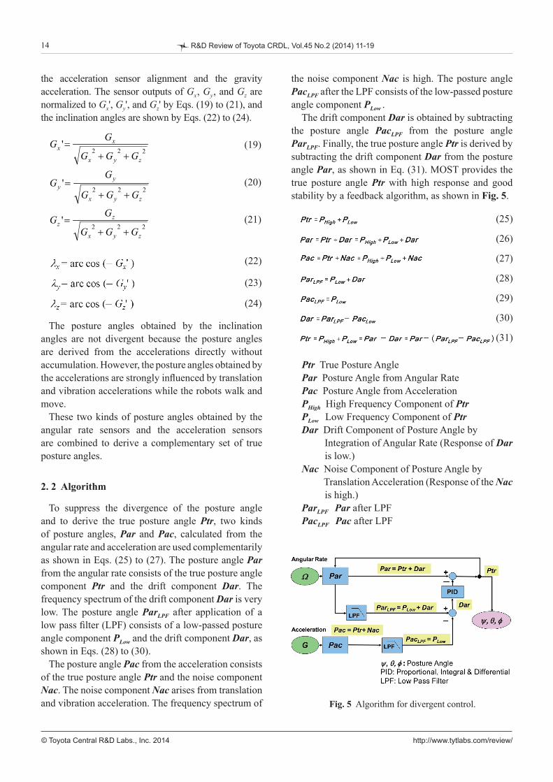
To suppress the divergence of the posture angle and to derive the true posture angle Ptr, two kinds of posture angles, Par and Pac, calculated from the angular rate and acceleration are used complementarily as shown in Eqs. (25) to (27). The posture angle Par from the angular rate consists of the true posture angle component Ptr and the drift component Dar. The frequency spectrum of the drift component Dar is very low. The posture angle ParLPF after application of a low pass filter (LPF) consists of a low-passed posture angle component PLow and the drift component Dar, as shown in Eqs. (28) to (30).
The posture angle Pac from the acceleration consists of the true posture angle Ptr and the noise component Nac. The noise component Nac arises from translation and vibration acceleration. The frequency spectrum of
the noise component Nac is high. The posture angle PacLPF after the LPF consists of the low-passed posture angle component PLow .
The drift component Dar is obtained by subtracting the posture angle PacLPF from the posture angle ParLPF. Finally, the true posture angle Ptr is derived by subtracting the drift component Dar from the posture angle Par, as shown in Eq. (31). MOST provides the true posture angle Ptr with high response and good stability by a feedback algorithm, as shown in Fig. 5.
Ptr True Posture Angle Par Posture Angle from Angular Rate Pac Posture Angle from Acceleration PHigh High Frequency Component of Ptr PLow Low Frequency Component of Ptr Dar Drift Component of Posture Angle by Integration of Angular Rate (Response of Dar is low.) Nac Noise Component of Posture Angle by Translation Acceleration (Response of the Nac is high.) ParLPF Par after LPF PacLPF Pac after LPF
Fig. 5 Algorithm for divergent control.
(19)
(20)
(21)
(22)
(23)
(24)
(25)
(26)
(27)
(28)
(29)
(30)
(31)
222'
zyx
xx
GGG
GG
++=
222'
zyx
yy
GGG
GG
++=
222'
zyx
zz
GGG
GG
++=
15
© Toyota Central R&D Labs., Inc. 2014 http://www.tytlabs.com/review/
R&D Review of Toyota CRDL, Vol.45 No.2 (2014) 11-19
3. Structure of MOST
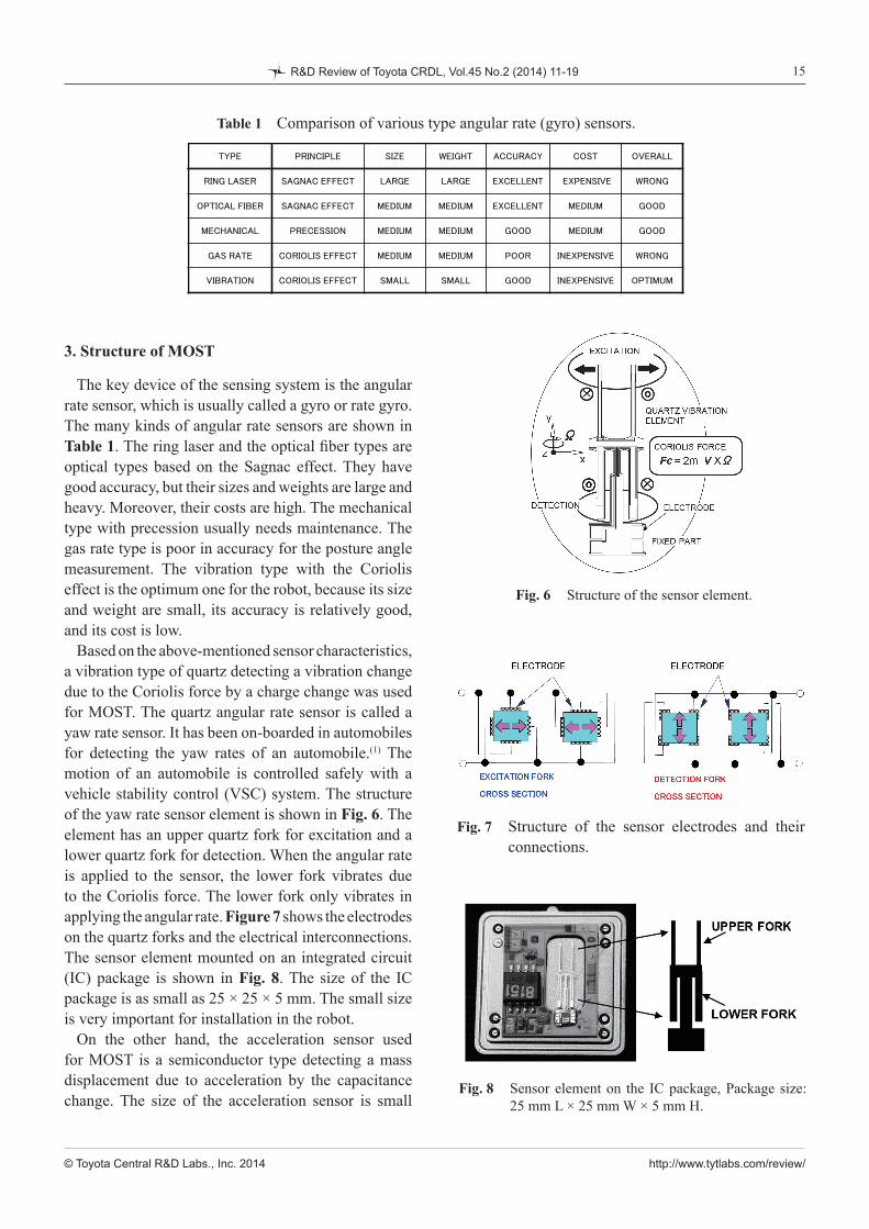
The key device of the sensing system is the angular rate sensor, which is usually called a gyro or rate gyro. The many kinds of angular rate sensors are shown in Table 1. The ring laser and the optical fiber types are optical types based on the Sagnac effect. They have good accuracy, but their sizes and weights are large and heavy. Moreover, their costs are high. The mechanical type with precession usually needs maintenance. The gas rate type is poor in accuracy for the posture angle measurement. The vibration type with the Coriolis effect is the optimum one for the robot, because its size and weight are small, its accuracy is relatively good, and its cost is low.
Based on the above-mentioned sensor characteristics, a vibration type of quartz detecting a vibration change due to the Coriolis force by a charge change was used for MOST. The quartz angular rate sensor is called a yaw rate sensor. It has been on-boarded in automobiles for detecting the yaw rates of an automobile.(1) The motion of an automobile is controlled safely with a vehicle stability control (VSC) system. The structure of the yaw rate sensor element is shown in Fig. 6. The element has an upper quartz fork for excitation and a lower quartz fork for detection. When the angular rate is applied to the sensor, the lower fork vibrates due to the Coriolis force. The lower fork only vibrates in applying the angular rate. Figure 7 shows the electrodes on the quartz forks and the electrical interconnections. The sensor element mounted on an integrated circuit (IC) package is shown in Fig. 8. The size of the IC package is as small as 25 × 25 × 5 mm. The small size is very important for installation in the robot.
On the other hand, the acceleration sensor used for MOST is a semiconductor type detecting a mass displacement due to acceleration by the capacitance change. The size of the acceleration sensor is small
Table 1 Comparison of various type angular rate (gyro) sensors.
Fig. 6 Structure of the sensor element.
Fig. 7 Structure of the sensor electrodes and their connections.
Fig. 8 Sensor element on the IC package, Package size: 25 mm L × 25 mm W × 5 mm H.
TYPE PRINCIPLE SIZE WEIGHT ACCURACY COST OVERALL
RING LASER SAGNAC EFFECT LARGE LARGE EXCELLENT EXPENSIVE WRONG
OPTICAL FIBER SAGNAC EFFECT MEDIUM MEDIUM EXCELLENT MEDIUM GOOD
MECHANICAL PRECESSION MEDIUM MEDIUM GOOD MEDIUM GOOD
GAS RATE CORIOLIS EFFECT MEDIUM MEDIUM POOR INEXPENSIVE WRONG
VIBRATION CORIOLIS EFFECT SMALL SMALL GOOD INEXPENSIVE OPTIMUM

16
© Toyota Central R&D Labs., Inc. 2014 http://www.tytlabs.com/review/
R&D Review of Toyota CRDL, Vol.45 No.2 (2014) 11-19
and it is also used in the VSC system. The angular rate and acceleration sensors are
made by micro electro mechanical systems (MEMS) technology. Since these sensors are used for controlling automobiles, they have high reliability over a wide temperature range and long-term durability. Such characteristics are considered to be quite important for highly reliable posture-angle control.
Then, the inertial force sensing system (MOST) consists of the above-mentioned three angular rate sensors, three acceleration sensors, and a digital signal processor (DSP), as shown in Fig. 9. The three angular rate sensors and the three acceleration sensors are arranged perpendicularly to each other. The temperature offset and sensitivity changes of the angular rate and acceleration sensors are compensated with the DSP. The misalignment of the perpendicular settings of the three sensors is compensated with a compensation matrix. The main role of the DSP is real-time calculation of the posture angles with the outputs of the angular rate and the acceleration sensors. It is all in one package, as shown in Fig. 10. The output signals of MOST are three axial posture angles, three axial angular rates, and three axial accelerations. The sensor signals are outputted with an RS232C digital communication interface. (2,3)
4. Results
MOST was evaluated on a three-axis stage. MOST was set up as the sensor coordinates parallel to the stage axes. The stage provided MOST with roll, pitch, and yaw motions independently. The stage oscillated MOST along the three axes like a tone burst wave.
One of the tone burst patterns was a three-axis rotation
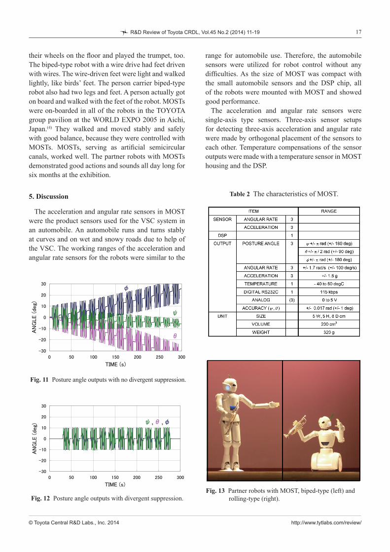
in phase, 5 times in 17 seconds and keeping still in 4 seconds. MOST was oscillated at the amplitude of +/– 0.17 rad (+/– 10 deg). This pattern simulated one of the robot walk patterns. In this case, the robot walked 5 + 5 steps and rested, and walked. The posture angle outputs of MOST without the divergence suppression method are shown in Fig. 11. Each posture angle was changed according to the applied oscillation, but, in the still state, the posture angles of y, q, and f drifted and were divergent over time.
The posture angle outputs of MOST with the divergence suppression method are shown in Fig. 12. In the still state, the posture angles of y, q, and f did not drift over time. The three posture angles overlapped each other in this case. The drift of the posture angle of f along the z direction was controlled to zero in this test.
The characteristics of MOST are listed in Table 2. The measurement ranges of the posture angles of y, q, and f were +/– p rad (+/– 180 deg), +/– p/2 rad (+/– 90 deg), and +/– p rad (+/– 180 deg), respectively. The angular rate range was +/– 1.7 rad/s (+/– 100 deg/s). The acceleration range was +/– 1.5 g. The attained accuracy of the posture angles of y and q was +/– 0.017 rad (+/– 1 deg). The size of MOST was 5 × 5 × 8 cm, and the volume was 200 cm3. The weight was as small as 320 g. The signals were outputted with the RS232C digital signal in a 10 msperiod. The speed of the RS232C was 115 kbps.
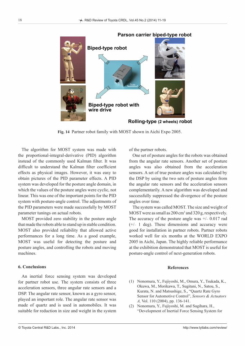
MOST was installed in the partner robots, as shown in Figs. 13 and 14. The biped-type robots stood in a stable state, walked on their two legs and feet, and played the trumpet. The rolling-type robots stayed upright like an inverted pendulum and did not fall over. The rolling-type robots moved and spun with
Fig. 10 Photograph of MOST.
5cm
Fig. 9 Block diagram of the inertial force sensing system.
DSPPosture Calc.
Algorithm
Gz
Angular Rate Sensor
Posture Angle Angular RateAcceleration
Ωz
Ωy
Ωx
Gy
Gx
Acceleration Sensor
17
© Toyota Central R&D Labs., Inc. 2014 http://www.tytlabs.com/review/
R&D Review of Toyota CRDL, Vol.45 No.2 (2014) 11-19
their wheels on the floor and played the trumpet, too. The biped-type robot with a wire drive had feet driven with wires. The wire-driven feet were light and walked lightly, like birds’ feet. The person carrier biped-type robot also had two legs and feet. A person actually got on board and walked with the feet of the robot. MOSTs were on-boarded in all of the robots in the TOYOTA group pavilion at the WORLD EXPO 2005 in Aichi, Japan.(4) They walked and moved stably and safely with good balance, because they were controlled with MOSTs. MOSTs, serving as artificial semicircular canals, worked well. The partner robots with MOSTs demonstrated good actions and sounds all day long for six months at the exhibition.
5. Discussion
The acceleration and angular rate sensors in MOST were the product sensors used for the VSC system in an automobile. An automobile runs and turns stably at curves and on wet and snowy roads due to help of the VSC. The working ranges of the acceleration and angular rate sensors for the robots were similar to the
range for automobile use. Therefore, the automobile sensors were utilized for robot control without any difficulties. As the size of MOST was compact with the small automobile sensors and the DSP chip, all of the robots were mounted with MOST and showed good performance.
The acceleration and angular rate sensors were single-axis type sensors. Three-axis sensor setups for detecting three-axis acceleration and angular rate were made by orthogonal placement of the sensors to each other. Temperature compensations of the sensor outputs were made with a temperature sensor in MOST housing and the DSP.
Fig. 11 Posture angle outputs with no divergent suppression.
Fig. 12 Posture angle outputs with divergent suppression.Fig. 13 Partner robots with MOST, biped-type (left) and rolling-type (right).
Table 2 The characteristics of MOST.
18
© Toyota Central R&D Labs., Inc. 2014 http://www.tytlabs.com/review/
R&D Review of Toyota CRDL, Vol.45 No.2 (2014) 11-19
The algorithm for MOST system was made with the proportional-integral-derivative (PID) algorithm instead of the commonly used Kalman filter. It was difficult to understand the Kalman filter coefficient effects as physical images. However, it was easy to obtain pictures of the PID parameter effects. A PID system was developed for the posture angle domain, in which the values of the posture angles were cyclic, not linear. This was one of the important points for the PID system with posture-angle control. The adjustments of the PID parameters were made successfully by MOST parameter tunings on actual robots.
MOST provided zero stability in the posture angle that made the robots able to stand up in stable condition. MOST also provided reliability that allowed active performances for a long time. As a good example, MOST was useful for detecting the posture and posture angles, and controlling the robots and moving machines.
6. Conclusions
An inertial force sensing system was developed for partner robot use. The system consists of three acceleration sensors, three angular rate sensors and a DSP. The angular rate sensor, known as a gyro sensor, played an important role. The angular rate sensor was made of quartz and is used in automobiles. It was suitable for reduction in size and weight in the system
of the partner robots. One set of posture angles for the robots was obtained
from the angular rate sensors. Another set of posture angles was also obtained from the acceleration sensors. A set of true posture angles was calculated by the DSP by using the two sets of posture angles from the angular rate sensors and the acceleration sensors complementarily. A new algorithm was developed and successfully suppressed the divergence of the posture angles over time.
The system was called MOST. The size and weight of MOST were as small as 200 cm3 and 320 g, respectively. The accuracy of the posture angle was +/– 0.017 rad (+/– 1 deg). These dimensions and accuracy were good for installation in partner robots. Partner robots worked well for six months at the WORLD EXPO 2005 in Aichi, Japan. The highly reliable performance at the exhibition demonstrated that MOST is useful for posture-angle control of next-generation robots.
References
(1) Nonomura, Y., Fujiyoshi, M., Omura, Y., Tsukada, K., Okuwa, M., Morikawa, T., Sugitani, N., Satou, S., Kurata, N. and Matsushige, S., “Quartz Rate Gyro Sensor for Automotive Control”, Sensors & Actuators A, Vol. 110 (2004), pp. 136-141.
(2) Nonomura, Y., Fujiyoshi, M. and Sugihara, H., “Development of Inertial Force Sensing System for
Fig. 14 Partner robot family with MOST shown in Aichi Expo 2005.
5cm5cm
Biped-type robot with wire drive
Biped-type robot
Parson carrier biped-type robot
Rolling-type (2 wheels) robot
19
© Toyota Central R&D Labs., Inc. 2014 http://www.tytlabs.com/review/
R&D Review of Toyota CRDL, Vol.45 No.2 (2014) 11-19
Partner Robots”, Proceedings of the 23rd Sensor Symposium (2006), pp. 55-59.
(3) Nonomura, Y., Fujiyoshi, M., Sugihara, H., “Inertial Force Sensing System for Partner Robots”, IEEE SENSORS 2006 (2006) , pp. 1325-1328.
(4) TOYOTA MOTOR CORP, “TOYOTA. CO. JP -NEWS RELEASE-”
<http//:www.toyota.co.jp/en/news/04/1203_1d.html>, (2005), (accessed 2014-05-20).
Figs. 1-4, 6-7, 9-13 and Table 2Partially reprinted and modified from Proceedings of the 23rd Sensor Symposium (2006), pp. 55-59, Nonomura, Y., Fujiyoshi, M. and Sugihara, H., Development of Inertial Force Sensing System for Partner Robots, © 2006 The Institute of Electrical Engineers of Japan, with permission from the Institute of Electrical Engineers of Japan.
Figs. 5 and 8Reprinted from IEEE SENSORS, (2006), pp. 1325-1328, Nonomura, Y., Fujiyoshi, M. and Sugihara, H., Inertial Force Sensing System for Partner Robots, © 2006 IEEE, with permission from IEEE.
Yutaka Nonomura Research Fields: - Sensors for Automobiles - MEMS (Micro Electro Mechanical Systems) Academic Degree: Dr.Eng. Academic Societies: - The Magnetics Society of Japan - The Japan Society of Applied Physics - The Institute of Electrical Engineers of Japan - IEEE Award: - Outstanding Paper Award at Transducers '11, 2011
Motohiro Fujiyoshi Research Field: - MEMS Sensor Academic Degree: Dr.Eng. Academic Societies: - IEEE - The Institute of Electrical Engineers of Japan Award: - Outstanding Paper Award at Transducers '11, 2011
Hisayoshi Sugihara* Research Field: - Development of Personal Mobility Academic Societies: - The Japan Society of Mechanical Engineers - The Robotics Society of Japan
*TOYOTA MOTOR CORPORATION