Embed Size (px)
Citation preview
– 225 –
Masataka YOSHIDA* Masato KITA* Hirofumi ATARASHI*
Development of Hybrid System for Formula One
ABSTRACT
In 2009, the regulations for the Formula One World Championship were amended to allow the use of kinetic energyrecovery systems (KERS). The new regulations stipulated that the KERS drive shaft be limited to the rear wheels,that output should be no more than 60 kW, and that the amount of energy used per lap be no more than 400 kJ.Honda had been conducting R&D in this area since the summer of 2007, and had developed a high speed, high output,direct oil-cooled motor, a water-cooled power control unit (PCU) which integrated a motor drive inverter unit andvoltage control system, as well as a high power density lithium ion battery, all based on being small and lightweightenough for Formula One characteristics.
This system was first used to drive on straight roads in April 2008, and in May of that year Honda beat out otherteams to conduct the world’s first driving tests in an actual vehicle at the Silverstone Circuit, where the technology’ssuperiority and high level of safety were proven.
* Automobile R&D Center
1. Introduction
Honda has been developing electric vehicles, fuel cellelectric vehicles and hybrid vehicles to find alternativesto fossil fuels, reduce emissions and mitigate the impactof automobiles on global warming.
As for the Formula One World Championship, theregulation amendments of 2009 allowed usage of KERS,which recovers and utilizes braking energy as drivepower assist. To work with the new rules, Honda chosefor its energy recovery method an electrical hybridsystem and proceeded with development for use inFormula One based on the electric drive technology ithad been developing.
Because the maximum output and the amount ofassist energy that can be used per lap are stipulated byregulations, this development focused on makingequipment as small and lightweight as possible with highoutput and high torque technology without changing thehigh level of dynamic performance unique to racing cars,and therefore Honda developed a motor, PCU andlithium ion battery capable of installation on a racing car.Honda additionally achieved high responsiveness to meetthe requirement for output characteristics during racing.
Development began in earnest in the summer of2007, and in just nine months, actual driving tests wereconducted using the prototype vehicle RA1082 (a vehiclebuilt to check functionality), and subsequently KERSwas run at full power on a racing course for the firsttime in the Formula One environment. Based on thebasic functions that had been confirmed with the
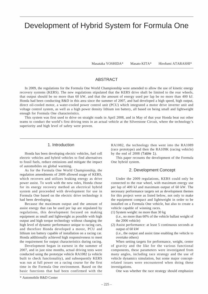
RA1082, the technology then went into the RA1089(race prototype) and then the RA109K (racing vehicle)by the end of 2008 (Table 1).
This paper recounts the development of the FormulaOne hybrid system.
2. Development Concept
Under the 2009 regulations, KERS could only beconnected to the rear wheel, with maximum energy useper lap of 400 kJ and maximum output of 60 kW. Thenecessary performance targets set as development themesfor this project were as listed below, not only to makethe equipment compact and lightweight in order to beinstalled on a Formula One vehicle, but also to create avehicle capable of winning races.(1) System weight: no more than 30 kg
(i.e., no more than 60% of the vehicle ballast weight ofthe 2006 vehicle)
(2) Assist performance: at least 5 continuous seconds atoutput of 60 kW(i.e., the output and assist time enabling the vehicle toovertake others)When setting targets for performance, weight, center
of gravity and the like for the various functionalcomponents, these parameters were investigated frommany angles, including race strategy and the use ofvehicle dynamics simulation, but some major concept-related issues were encountered when doing theseinvestigations.
One was whether the race strategy should emphasize
– 226 –
Development of Hybrid System for Formula One
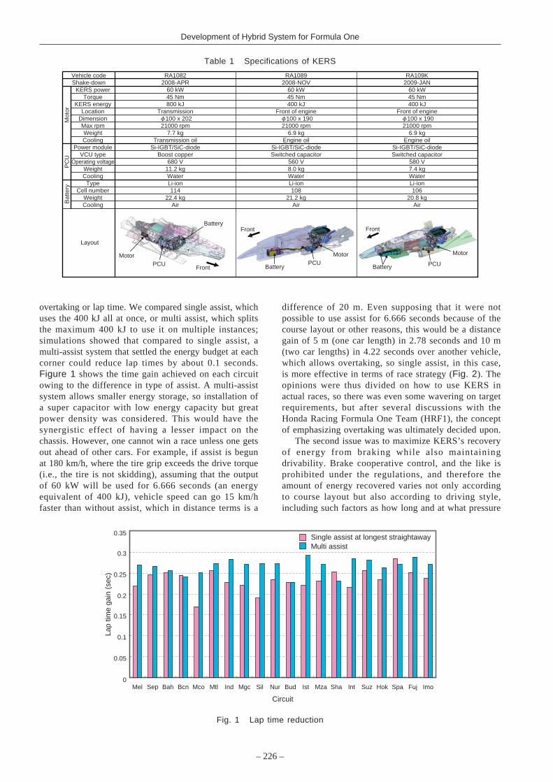
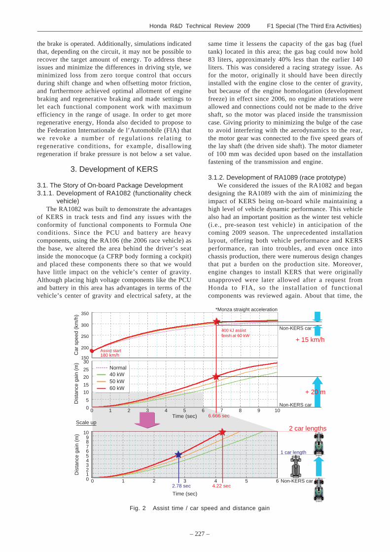
overtaking or lap time. We compared single assist, whichuses the 400 kJ all at once, or multi assist, which splitsthe maximum 400 kJ to use it on multiple instances;simulations showed that compared to single assist, amulti-assist system that settled the energy budget at eachcorner could reduce lap times by about 0.1 seconds.Figure 1 shows the time gain achieved on each circuitowing to the difference in type of assist. A multi-assistsystem allows smaller energy storage, so installation ofa super capacitor with low energy capacity but greatpower density was considered. This would have thesynergistic effect of having a lesser impact on thechassis. However, one cannot win a race unless one getsout ahead of other cars. For example, if assist is begunat 180 km/h, where the tire grip exceeds the drive torque(i.e., the tire is not skidding), assuming that the outputof 60 kW will be used for 6.666 seconds (an energyequivalent of 400 kJ), vehicle speed can go 15 km/hfaster than without assist, which in distance terms is a
Table 1 Specifications of KERS
RA1082 RA1089 RA109K2008-APR 2008-NOV 2009-JAN
KERS power 60 kW 60 kW 60 kWTorque 45 Nm 45 Nm 45 Nm
KERS energy 800 kJ 400 kJ 400 kJLocation Transmission Front of engine Front of engine
Dimension 100 x 202 100 x 190 100 x 190Max rpm 21000 rpm 21000 rpm 21000 rpmWeight 7.7 kg 6.9 kg 6.9 kgCooling Transmission oil Engine oil Engine oil
Power module Si-IGBT/SiC-diode Si-IGBT/SiC-diode Si-IGBT/SiC-diodeVCU type Boost copper Switched capacitor Switched capacitor
Operating voltage 680 V 560 V 580 VWeight 11.2 kg 8.0 kg 7.4 kgCooling Water Water Water
Type Li-ion Li-ion Li-ionCell number 114 108 106
Weight 22.4 kg 21.2 kg 20.8 kgCooling Air Air Air
Vehicle code
Layout
Mot
or
Shake-down
PC
UB
atte
ry
MotorPCU
Battery
Battery BatteryPCU PCU
Motor Motor
Front
Front Front
difference of 20 m. Even supposing that it were notpossible to use assist for 6.666 seconds because of thecourse layout or other reasons, this would be a distancegain of 5 m (one car length) in 2.78 seconds and 10 m(two car lengths) in 4.22 seconds over another vehicle,which allows overtaking, so single assist, in this case,is more effective in terms of race strategy (Fig. 2). Theopinions were thus divided on how to use KERS inactual races, so there was even some wavering on targetrequirements, but after several discussions with theHonda Racing Formula One Team (HRF1), the conceptof emphasizing overtaking was ultimately decided upon.
The second issue was to maximize KERS’s recoveryof energy from braking while also maintainingdrivability. Brake cooperative control, and the like isprohibited under the regulations, and therefore theamount of energy recovered varies not only accordingto course layout but also according to driving style,including such factors as how long and at what pressure
0
0.05
0.1
0.15
0.2
0.25
0.3
0.35
Mel Sep Bah Bcn Mco Mtl Ind Mgc Sil Nur Bud Ist Mza Sha Int Suz Hok Spa Fuj Imo
Circuit
Lap
time
gain
(se
c)
Single assist at longest straightawayMulti assist
Fig. 1 Lap time reduction
Honda R&D Technical Review 2009 F1 Special (The Third Era Activities)
– 227 –
the brake is operated. Additionally, simulations indicatedthat, depending on the circuit, it may not be possible torecover the target amount of energy. To address theseissues and minimize the differences in driving style, weminimized loss from zero torque control that occursduring shift change and when offsetting motor friction,and furthermore achieved optimal allotment of enginebraking and regenerative braking and made settings tolet each functional component work with maximumefficiency in the range of usage. In order to get moreregenerative energy, Honda also decided to propose tothe Federation Internationale de l’Automobile (FIA) thatwe revoke a number of regulations relating toregenerative conditions, for example, disallowingregeneration if brake pressure is not below a set value.
3. Development of KERS
3.1. The Story of On-board Package Development3.1.1. Development of RA1082 (functionality check
vehicle)The RA1082 was built to demonstrate the advantages
of KERS in track tests and find any issues with theconformity of functional components to Formula Oneconditions. Since the PCU and battery are heavycomponents, using the RA106 (the 2006 race vehicle) asthe base, we altered the area behind the driver’s seatinside the monocoque (a CFRP body forming a cockpit)and placed these components there so that we wouldhave little impact on the vehicle’s center of gravity.Although placing high voltage components like the PCUand battery in this area has advantages in terms of thevehicle’s center of gravity and electrical safety, at the
same time it lessens the capacity of the gas bag (fueltank) located in this area; the gas bag could now hold83 liters, approximately 40% less than the earlier 140liters. This was considered a racing strategy issue. Asfor the motor, originally it should have been directlyinstalled with the engine close to the center of gravity,but because of the engine homologation (developmentfreeze) in effect since 2006, no engine alterations wereallowed and connections could not be made to the driveshaft, so the motor was placed inside the transmissioncase. Giving priority to minimizing the bulge of the caseto avoid interfering with the aerodynamics to the rear,the motor gear was connected to the five speed gears ofthe lay shaft (the driven side shaft). The motor diameterof 100 mm was decided upon based on the installationfastening of the transmission and engine.
3.1.2. Development of RA1089 (race prototype)We considered the issues of the RA1082 and began
designing the RA1089 with the aim of minimizing theimpact of KERS being on-board while maintaining ahigh level of vehicle dynamic performance. This vehiclealso had an important position as the winter test vehicle(i.e., pre-season test vehicle) in anticipation of thecoming 2009 season. The unprecedented installationlayout, offering both vehicle performance and KERSperformance, ran into troubles, and even once intochassis production, there were numerous design changesthat put a burden on the production site. Moreover,engine changes to install KERS that were originallyunapproved were later allowed after a request fromHonda to FIA, so the installation of functionalcomponents was reviewed again. About that time, the
*Monza straight acceleration
400 kJ assist�finish at 60 kW
2.78 sec 4.22 sec
Scale up
1 car length
2 car lengths
6.666 sec
0123456789
10
0 1 2 3 4 5 6
Time (sec)
Dis
tanc
e ga
in (
m)
150
200
250
300
350
Car
spe
ed (
km/h
)
0
5
10
15
20
25
30
0 1 2 3 4 5 6 7 8 9 10Time (sec)
Dis
tanc
e ga
in (
m)
+ 15 km/h
+ 20 m
40 kW50 kW60 kW
Normal
Non-KERS car
Non-KERS car
Non-KERS car
Assist start�180 km/h
Fig. 2 Assist time / car speed and distance gain
– 228 –
Development of Hybrid System for Formula One
time to decide the chassis layout for RA1089 wasalready coming soon, but Honda felt that vehicledynamic performance was the number one priority andso, in a short period of time, worked with the HRF1engineers to modify the engine and reinvestigate thecooling specifications of functional components and theinstallation position as determined by all items, includingsafety in the event of collision. As a result, from themany ideas proposed, it was decided to install the motoron the engine front side, the PCU in the left side pot,and the battery in the monocoque front keel. Table 2shows a comparative investigation based on motorinstallation position. This decision not only made itnewly necessary to have a motor gear train thatconnected the engine and motor drive shaft, but therewas also an urgent need to ensure toughness againstcollision for the PCU and battery located outside themonocoque and provide for electrical safety withunprecedented techniques. It was decided to give thesethe highest priority and reinvestigate the specificationsof functional components from the beginning. This putmuch pressure on the period of stand-alone testing forthe PCU and battery, and meant that system launchwould have to be taken place in a short period of time.
The next issue was the relative position between thegas bag and motor. If the engine’s motor drive istransmitted directly to the crank shaft, it is necessary toput a recess around the gas bag, which is located in frontof the crank shaft, of a volume equivalent to the motor.The motor was offset to the left side where it would notimpact aerodynamics and the gear train was placedbetween the back end of the monocoque (the bulkhead)and the engine so the loss of gas bag volume wasminimized as much as possible.
Because the functional components underwentcompletely new development, the challenging work,performed both in Japan and in the UK, dragged on fora long time, so the completion of the RA1089 wasdelayed. As such, the system check was not in time forthe original target of the season’s first winter test inNovember, and the target was changed to the secondwinter test.
3.1.3. Development of the RA109K (racing specsvehicle)
The RA109K was designed as the racing vehicle.KERS components were located in about the sameposition as in the RA1089, but in the RA109K, theperiphery of the engine cowl, one of the aerodynamiccomponents, was made smaller than in the RA1089, andit was necessary to review from the beginning the formsof the PCU and battery located inside the cowl.Aerodynamic performance is affected by wind tunneltesting time, and therefore aerodynamic componentswere first produced with a target of being ready for theopening race in March with subsequent updatesfollowing in turn. However, the specifications of KERScomponents cannot easily be changed because we takeso long to produce and check for reliability. To ensuredevelopment of specifications meeting both these needs,
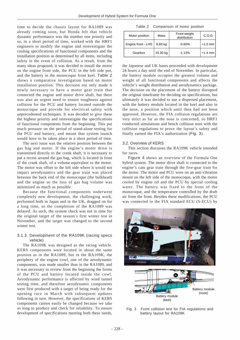
the Japanese and UK bases proceeded with development24 hours a day until the end of November. In particular,the battery module occupies the greatest volume andweight of all functional components and affects thevehicle’s weight distribution and aerodynamics package.The decision on the placement of the battery disruptedthe original timeframe for deciding on specifications, butultimately it was decided to use a dispersed placement,with the battery module located in the keel and also inthe nose, a position which until then had not beenapproved. However, the FIA collision regulations arevery strict as far as the nose is concerned, so HRF1conducted simulations and bench collision tests with thecollision regulations to prove the layout’s safety andfinally earned the FIA’s authorization (Fig. 3).
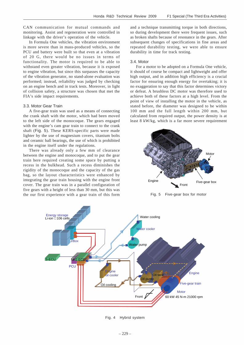
3.2. Overview of KERSThis section discusses the RA109K vehicle intended
for races.Figure 4 shows an overview of the Formula One
hybrid system. The motor drive shaft is connected to theengine’s cam gear train through the five-gear train forthe motor. The motor and PCU were on an anti-vibrationmount on the left side of the monocoque, with the motorcooled by engine oil and the PCU by special coolingwater. The battery was fixed to the front of themonocoque, and the temperature controlled by the draftair from the front. Besides these modifications, the PCUwas connected to the FIA standard ECU (S-ECU) by
Table 2 Comparison of motor position
Motor position MassFront-weight�distribution
C.O.G
Engine front - LHS +1.0 mm-0.60%8.69 kg
Gearbox +1.4 mm-1.13%10.30 kg
Fig. 3 Front collision test for FIA regulations andbattery layout for RA109K
Battery module�(nose)
Battery module�(keel)
Honda R&D Technical Review 2009 F1 Special (The Third Era Activities)
– 229 –
CAN communication for mutual commands andmonitoring. Assist and regeneration were controlled inlinkage with the driver’s operation of the vehicle.
In Formula One vehicles, the vibration environmentis more severe than in mass-produced vehicles, so thePCU and battery were built so that even at a vibrationof 20 G, there would be no issues in terms offunctionality. The motor is required to be able towithstand even greater vibration, because it is exposedto engine vibration, but since this surpasses the capacityof the vibration generator, no stand-alone evaluation wasperformed; instead, reliability was judged by checkingon an engine bench and in track tests. Moreover, in lightof collision safety, a structure was chosen that met theFIA’s side impact requirements.
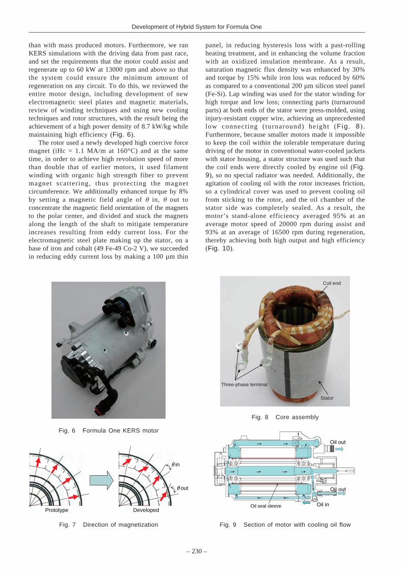
3.3. Motor Gear TrainA five-gear train was used as a means of connecting
the crank shaft with the motor, which had been movedto the left side of the monocoque. The gears engagedwith the engine’s cam gear train to connect to the crankshaft (Fig. 5). These KERS-specific parts were madelighter by the use of magnesium covers, titanium boltsand ceramic ball bearings, the use of which is prohibitedin the engine itself under the regulations.
There was already only a few mm of clearancebetween the engine and monocoque, and to put the geartrain here required creating some space by putting arecess in the bulkhead. Such a recess diminishes therigidity of the monocoque and the capacity of the gasbag, so the layout characteristics were enhanced byintegrating the gear train housing with the engine frontcover. The gear train was in a parallel configuration offive gears with a height of less than 30 mm, but this wasthe our first experience with a gear train of this form
and a technique transmitting torque in both directions,so during development there were frequent issues, suchas broken shafts because of resonance in the gears. Aftersubsequent changes of specifications in fine areas andrepeated durability testing, we were able to ensuredurability in time for track testing.
3.4. MotorFor a motor to be adopted on a Formula One vehicle,
it should of course be compact and lightweight and offerhigh output, and in addition high efficiency is a crucialfactor for ensuring enough energy for overtaking; it isno exaggeration to say that this factor determines victoryor defeat. A brushless DC motor was therefore used toachieve both of these factors at a high level. From thepoint of view of installing the motor in the vehicle, asstated before, the diameter was designed to be within100 mm and the full length within 200 mm, butcalculated from required output, the power density is atleast 8 kW/kg, which is a far more severe requirement
Engine�oil cooler
60 kW 45 N-m 21000 rpm
Motor
Oil cooling
Water cooling
Five-gear train
Engine
Front
Oil tank
Energy storage
J/Box
Li-ion × 106 cells
PCUPCU
S-ECU M/G ECU
Oil pump
Water pump
Water cooler
Front
Motor
Engine Five-gear box
Fig. 4 Hybrid system
Fig. 5 Five-gear box for motor
– 230 –
Development of Hybrid System for Formula One
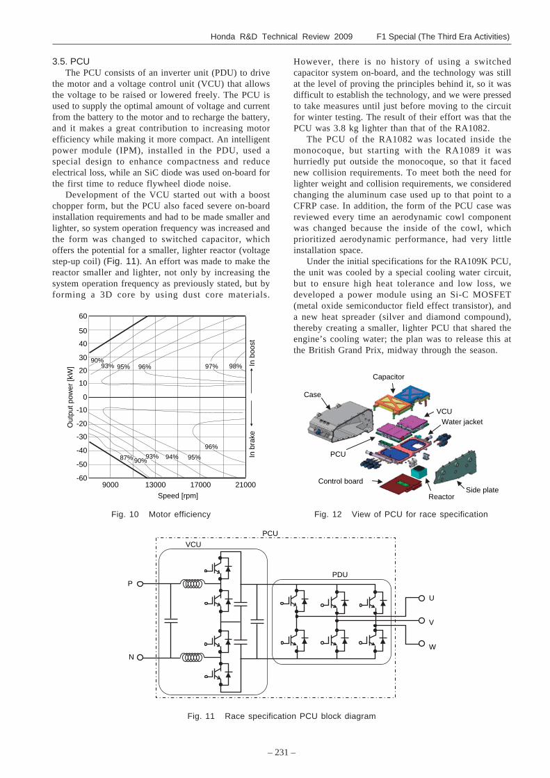
than with mass produced motors. Furthermore, we ranKERS simulations with the driving data from past race,and set the requirements that the motor could assist andregenerate up to 60 kW at 13000 rpm and above so thatthe system could ensure the minimum amount ofregeneration on any circuit. To do this, we reviewed theentire motor design, including development of newelectromagnetic steel plates and magnetic materials,review of winding techniques and using new coolingtechniques and rotor structures, with the result being theachievement of a high power density of 8.7 kW/kg whilemaintaining high efficiency (Fig. 6).
The rotor used a newly developed high coercive forcemagnet (iHc = 1.1 MA/m at 160°C) and at the sametime, in order to achieve high revolution speed of morethan double that of earlier motors, it used filamentwinding with organic high strength fiber to preventmagnet scattering, thus protecting the magnetcircumference. We additionally enhanced torque by 8%by setting a magnetic field angle of θ in, θ out toconcentrate the magnetic field orientation of the magnetsto the polar center, and divided and stuck the magnetsalong the length of the shaft to mitigate temperatureincreases resulting from eddy current loss. For theelectromagnetic steel plate making up the stator, on abase of iron and cobalt (49 Fe-49 Co-2 V), we succeededin reducing eddy current loss by making a 100 µm thin
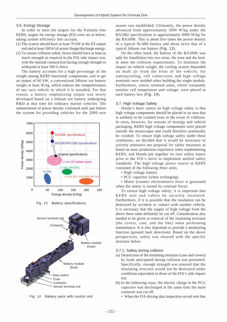
panel, in reducing hysteresis loss with a past-rollingheating treatment, and in enhancing the volume fractionwith an oxidized insulation membrane. As a result,saturation magnetic flux density was enhanced by 30%and torque by 15% while iron loss was reduced by 60%as compared to a conventional 200 µm silicon steel panel(Fe-Si). Lap winding was used for the stator winding forhigh torque and low loss; connecting parts (turnaroundparts) at both ends of the stator were press-molded, usinginjury-resistant copper wire, achieving an unprecedentedlow connect ing ( turnaround) height (Fig. 8 ) .Furthermore, because smaller motors made it impossibleto keep the coil within the tolerable temperature duringdriving of the motor in conventional water-cooled jacketswith stator housing, a stator structure was used such thatthe coil ends were directly cooled by engine oil (Fig.9), so no special radiator was needed. Additionally, theagitation of cooling oil with the rotor increases friction,so a cylindrical cover was used to prevent cooling oilfrom sticking to the rotor, and the oil chamber of thestator side was completely sealed. As a result, themotor’s stand-alone efficiency averaged 95% at anaverage motor speed of 20000 rpm during assist and93% at an average of 16500 rpm during regeneration,thereby achieving both high output and high efficiency(Fig. 10).
out
in
Prototype Developed
Fig. 6 Formula One KERS motor
Fig. 7 Direction of magnetization
Fig. 8 Core assembly
Fig. 9 Section of motor with cooling oil flow
Stator
Three-phase terminal
Coil end
Oil in�
Oil out�
Oil out�
Oil seal sleeve�
Honda R&D Technical Review 2009 F1 Special (The Third Era Activities)
– 231 –
3.5. PCUThe PCU consists of an inverter unit (PDU) to drive
the motor and a voltage control unit (VCU) that allowsthe voltage to be raised or lowered freely. The PCU isused to supply the optimal amount of voltage and currentfrom the battery to the motor and to recharge the battery,and it makes a great contribution to increasing motorefficiency while making it more compact. An intelligentpower module (IPM), installed in the PDU, used aspecial design to enhance compactness and reduceelectrical loss, while an SiC diode was used on-board forthe first time to reduce flywheel diode noise.
Development of the VCU started out with a boostchopper form, but the PCU also faced severe on-boardinstallation requirements and had to be made smaller andlighter, so system operation frequency was increased andthe form was changed to switched capacitor, whichoffers the potential for a smaller, lighter reactor (voltagestep-up coil) (Fig. 11). An effort was made to make thereactor smaller and lighter, not only by increasing thesystem operation frequency as previously stated, but byforming a 3D core by using dust core materials.
However, there is no history of using a switchedcapacitor system on-board, and the technology was stillat the level of proving the principles behind it, so it wasdifficult to establish the technology, and we were pressedto take measures until just before moving to the circuitfor winter testing. The result of their effort was that thePCU was 3.8 kg lighter than that of the RA1082.
The PCU of the RA1082 was located inside themonocoque, but starting with the RA1089 it washurriedly put outside the monocoque, so that it facednew collision requirements. To meet both the need forlighter weight and collision requirements, we consideredchanging the aluminum case used up to that point to aCFRP case. In addition, the form of the PCU case wasreviewed every time an aerodynamic cowl componentwas changed because the inside of the cowl, whichprioritized aerodynamic performance, had very littleinstallation space.
Under the initial specifications for the RA109K PCU,the unit was cooled by a special cooling water circuit,but to ensure high heat tolerance and low loss, wedeveloped a power module using an Si-C MOSFET(metal oxide semiconductor field effect transistor), anda new heat spreader (silver and diamond compound),thereby creating a smaller, lighter PCU that shared theengine’s cooling water; the plan was to release this atthe British Grand Prix, midway through the season.
Fig. 10 Motor efficiency
90%
9000� 21000�
60�
50�
40�
30�
20�
10�
0�
-10�
-20�
-30�
-40�
-50�
-60�
97% 98%96%95%90%
13000�
Speed [rpm]�
17000�
96%
95%94%93%87%
93%
In b
rake
�In
boo
st�
Out
put p
ower
[kW
]�
PCU
VCU
PDUP�
N�
U�
V�
W
Case
Capacitor
VCU
PCU
Water jacket
Control board
ReactorSide plate
Fig. 11 Race specification PCU block diagram
Fig. 12 View of PCU for race specification
– 232 –
Development of Hybrid System for Formula One
3.6. Energy StorageIn order to meet the targets for the Formula One
KERS, targets for energy storage (ES) were set as below,taking system efficiency into account.(1) The system should have at least 70 kW at the ES output
end and at least 500 kJ of actual charge/discharge energy.(2) To ensure collision safety, boxes should have at least as
much strength as required in the FIA side impact test,with the internal construction having enough strength towithstand at least 100 G-force.The battery accounts for a high percentage of the
weight among KERS functional components, and to getan output of 60 kW, a conventional lithium ion batteryweighs at least 30 kg, which reduces the competitivenessof any race vehicle in which it is installed. For thatreason, a battery emphasizing output was newlydeveloped based on a lithium ion battery undergoingR&D at that time for ordinary market vehicles. Theenhancement of power density continued until just beforethe system for providing vehicles for the 2009 race
Energy density (kJ/kg)
Ni-MHLi-ion (for EV)
0
1000
2000
50 100 150 200 250
5000
6000
3000
Pow
er d
ensi
ty (
W/k
g)
4000
7000
Original specifications
RA1082/RA1089 specifications
RA109K specifications
Li-ion (Hi power type)
Ni-MHLi-ion (for EV)
Original specifications
RA1082/RA1089 specifications
RA109K specifications
Li-ion (Hi power type)
Li-ion (for commercial use)Li-ion (for commercial use)
Battery module�(keel)
Battery module(nose)
Sensor terminal unit�
Contactor�
Main switch�Fuse�Contactor�Sensor terminal unit�
season was established. Ultimately, the power densityadvanced from approximately 5000 W/kg under theRA1082 specifications to approximately 6000 W/kg forthe RA109K. This is about five times the power densityof a typical Ni-MH battery and about twice that of atypical lithium ion battery (Fig. 13).
On the other hand, the battery of the RA109K wassplit for installation into two areas, the nose and the keel,to meet the collision requirements. To minimize theimpact on vehicle weight, the cooling system dependedon draft air from the front of the vehicle; forwaterproofing, cell connections and high voltageterminals were molded when building the single module.Furthermore, sensor terminal units, which constantlymonitor cell temperature and voltage, were placed ineach battery box (Fig. 14).
3.7. High Voltage SafetyHonda’s basic stance on high voltage safety is that
high voltage components should be placed in an area thatis unlikely to be crushed even in the event of collision.In races, however, for reasons of strategy and vehiclepackaging, KERS high voltage components were placedoutside the monocoque and could therefore potentiallybe crushed. To ensure high voltage safety under theseconditions, we decided that it would be necessary toactively announce our proposal for safety measures asbased on mass production experience when implementingKERS, and Honda put together its own safety stanceprior to the FIA’s move to implement unified safetystandards. The high voltage power source in KERSconsisted of the following three units.
• High voltage battery• PCU capacitor (when recharging)• Motor (counter electromotive force is generated
when the motor is turned by external force)To ensure high voltage safety, it is important that
KERS uni t and cables be securely insulated.Furthermore, if it is possible that the insulation can bedestroyed by accident or contact with another vehicle,it is necessary that the supply of high voltage from theabove three units definitely be cut off. Consideration alsoneeded to be given to removal of the insulating structure(the covers, case, and the like) when performingmaintenance. It is also important to provide a monitoringfunction (ground fault detection). Based on the aboveperspectives, safety was ensured with the specificstructure below.
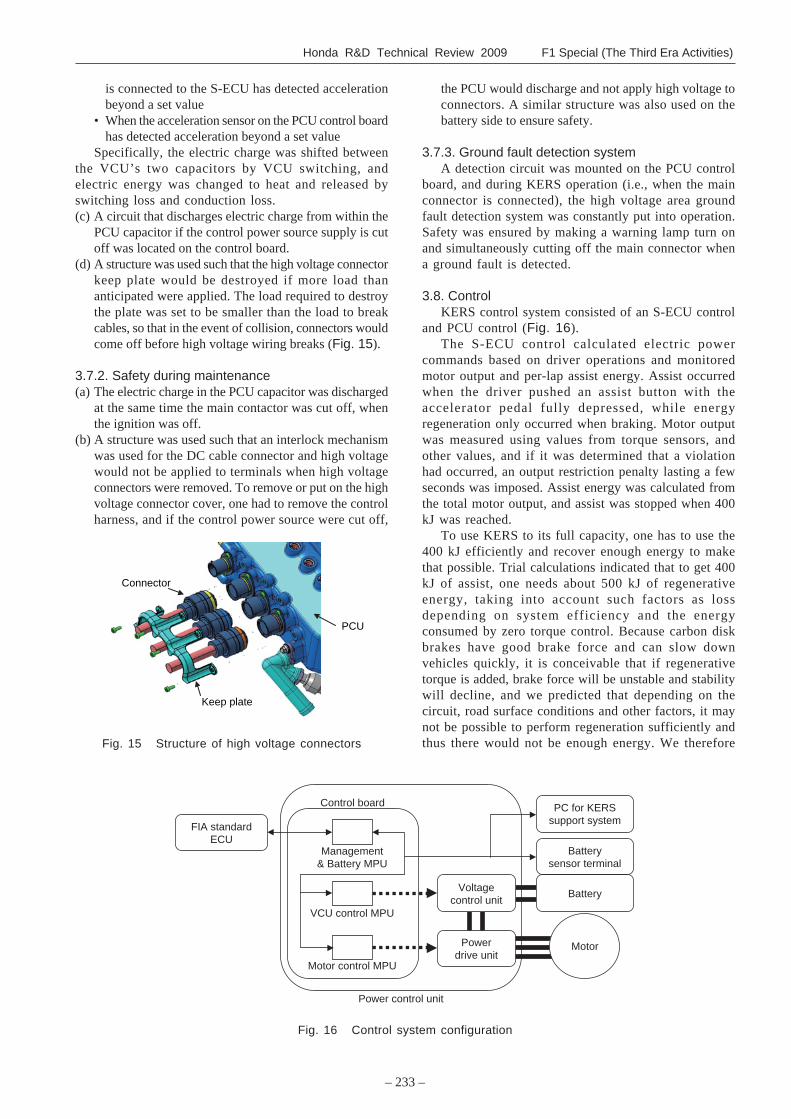
3.7.1. Safety during collision(a) Destruction of the insulating structure (case and covers)
by loads anticipated during collision was prevented.Specifically, enough strength was ensured that theinsulating structure would not be destroyed underconditions equivalent to those of the FIA’s side impacttest.
(b) In the following cases, the electric charge in the PCUcapacitor was discharged at the same time the maincontactor was cut off.• When the FIA driving data inspection record unit thatFig. 14 Battery pack with control unit
Fig. 13 Battery specifications
Honda R&D Technical Review 2009 F1 Special (The Third Era Activities)
– 233 –
Fig. 15 Structure of high voltage connectors
Keep plate
Connector
PCU
is connected to the S-ECU has detected accelerationbeyond a set value
• When the acceleration sensor on the PCU control boardhas detected acceleration beyond a set value
Specifically, the electric charge was shifted betweenthe VCU’s two capacitors by VCU switching, andelectric energy was changed to heat and released byswitching loss and conduction loss.(c) A circuit that discharges electric charge from within the
PCU capacitor if the control power source supply is cutoff was located on the control board.
(d) A structure was used such that the high voltage connectorkeep plate would be destroyed if more load thananticipated were applied. The load required to destroythe plate was set to be smaller than the load to breakcables, so that in the event of collision, connectors wouldcome off before high voltage wiring breaks (Fig. 15).
3.7.2. Safety during maintenance(a) The electric charge in the PCU capacitor was discharged
at the same time the main contactor was cut off, whenthe ignition was off.
(b) A structure was used such that an interlock mechanismwas used for the DC cable connector and high voltagewould not be applied to terminals when high voltageconnectors were removed. To remove or put on the highvoltage connector cover, one had to remove the controlharness, and if the control power source were cut off,
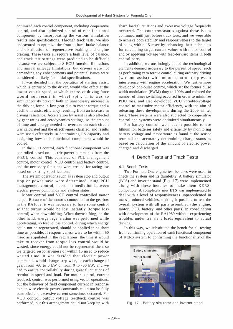
Fig. 16 Control system configuration
Power control unit�
Battery�
FIA standard�ECU
Voltage�control unit�
Motor control MPU�
VCU control MPU�
Power�drive unit�
Management�& Battery MPU�
Control board�
Battery�sensor terminal�
Motor�
PC for KERS�support system�
the PCU would discharge and not apply high voltage toconnectors. A similar structure was also used on thebattery side to ensure safety.
3.7.3. Ground fault detection systemA detection circuit was mounted on the PCU control
board, and during KERS operation (i.e., when the mainconnector is connected), the high voltage area groundfault detection system was constantly put into operation.Safety was ensured by making a warning lamp turn onand simultaneously cutting off the main connector whena ground fault is detected.
3.8. ControlKERS control system consisted of an S-ECU control
and PCU control (Fig. 16).The S-ECU control calculated electric power
commands based on driver operations and monitoredmotor output and per-lap assist energy. Assist occurredwhen the driver pushed an assist button with theaccelerator pedal fully depressed, while energyregeneration only occurred when braking. Motor outputwas measured using values from torque sensors, andother values, and if it was determined that a violationhad occurred, an output restriction penalty lasting a fewseconds was imposed. Assist energy was calculated fromthe total motor output, and assist was stopped when 400kJ was reached.
To use KERS to its full capacity, one has to use the400 kJ efficiently and recover enough energy to makethat possible. Trial calculations indicated that to get 400kJ of assist, one needs about 500 kJ of regenerativeenergy, taking into account such factors as lossdepending on system efficiency and the energyconsumed by zero torque control. Because carbon diskbrakes have good brake force and can slow downvehicles quickly, it is conceivable that if regenerativetorque is added, brake force will be unstable and stabilitywill decline, and we predicted that depending on thecircuit, road surface conditions and other factors, it maynot be possible to perform regeneration sufficiently andthus there would not be enough energy. We therefore
– 234 –
Development of Hybrid System for Formula One
optimized each control component, including cooperativecontrol, and also optimized control of each functionalcomponent by incorporating the various simulationresults into specifications. Through track tests, we alsoendeavored to optimize the front-to-back brake balanceand distribution of regenerative braking and enginebraking. These tasks all require a high level of balance,and track test settings were predicted to be difficultbecause we are subject to S-ECU function limitationsand annual mileage limitations, but drivers were notdemanding any enhancements and potential issues wereconsidered unlikely for initial specifications.
It was decided that the operation of starting assist,which is entrusted to the driver, would take effect at thelowest vehicle speed, at which excessive driving forcewould not resul t in wheel spin . This was tosimultaneously prevent both an unnecessary increase inthe driving force in low gear due to motor torque and adecline in assist efficiency resulting from an increase indriving resistance. Acceleration by assist is also affectedby gear ratios and aerodynamics settings, so the amountof time and energy needed to overtake on each circuitwas calculated and the effectiveness clarified, and resultswere used effectively in determining ES capacity anddesigning how each functional component would becooled.
In the PCU control, each functional component wascontrolled based on electric power commands from theS-ECU control. This consisted of PCU managementcontrol, motor control, VCU control and battery control,and the necessary functions were created for racing usebased on existing specifications.
The system operations such as system stop and outputstop or power save were determined using PCUmanagement control, based on mediation betweenelectric power commands and system status.
Motor control and VCU control controlled motoroutput. Because of the motor’s connection to the gearboxin the RA1082, it was necessary to have some controlso that torque would be lost instantly (torque losscontrol) when downshifting. When downshifting, on theother hand, energy regeneration was performed whiledecelerating, so torque loss control, during which energycould not be regenerated, should be applied in as shorttime as possible. If responsiveness were to be within 50msec as stipulated in the regulations, the time it wouldtake to recover from torque loss control would bewasted, since energy could not be regenerated then, sowe targeted responsiveness of within 15 msec to reducewasted time. It was decided that electric powercommands would change step-wise, at each change ofgear, from -60 to 0 kW or from 0 to -60 kW, and wehad to ensure controllability during great fluctuations ofrevolution speed and load. For motor control, currentfeedback control was performed using vector operations,but the behavior of field component current in responseto step-wise electric power commands could not be fullycontrolled and excessive current sometimes occurred. ForVCU control, output voltage feedback control wasperformed, but this arrangement could not keep up with
sharp load fluctuations and excessive voltage frequentlyoccurred. The countermeasures against these issuescontinued until just before track tests, and we were ableto achieve both stability and responsiveness to the targetof being within 15 msec by enhancing their techniquesfor calculating target current values with motor controland by applying voltage with feed-forward items in bothcontrol parts.
In addition, we unstintingly added the technologicalelements deemed necessary to the pursuit of speed, suchas performing zero torque control during ordinary driving(without assist) with motor control to preventinterference with engine acceleration. We furthermoredeveloped one-pulse control, which set the former pulsewidth modulation (PWM) duty to 100% and reduced thenumber of times switching occurred in order to minimizePDU loss, and also developed VCU variable-voltagecontrol to maximize motor efficiency, with the aim ofreleasing these developments during the 2009 wintertests. These systems were also subjected to cooperativecontrol and systems were optimized simultaneously.
For battery control, we made it possible to uselithium ion batteries safely and efficiently by monitoringbattery voltage and temperature as found at the sensorterminal and accurately determining charge status asbased on calculation of the amount of electric powercharged and discharged.
4. Bench Tests and Track Tests
4.1. Bench TestsTwo Formula One engine test benches were used, to
check the system and its durability. A battery simulator(BTS) and inverter stand (Fig. 17) were implementedalong with these benches to make them KERS-compatible. A completely new BTS was implemented todeal with a level of responsiveness unprecedented inmass produced vehicles, making it possible to test theoverall system with all parts assembled (the engine,motor, PCU, battery, and other parts) in coordinationwith development of the RA1089 without experiencingtroubles under transient loads equivalent to actualdriving.
In this way, we substituted the bench for all testingfrom confirming operation of each functional componentof KERS system to confirming the functionality of the
Inverter stand
Battery simulator
Fig. 17 Battery simulator and inverter stand
Honda R&D Technical Review 2009 F1 Special (The Third Era Activities)
– 235 –
overall system on an actual vehicle, including functionalassurance testing, and sought to bring KERS as a wholeto early fruition without the track tests that are soseverely restricted under the regulations.
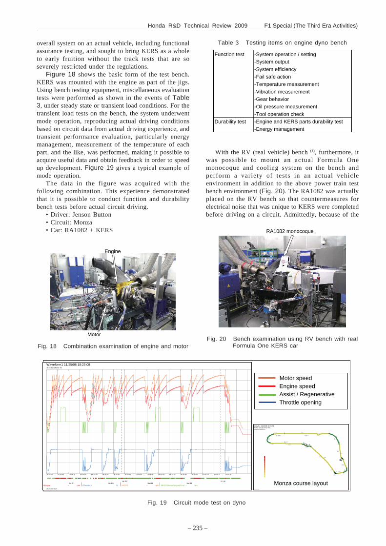
Figure 18 shows the basic form of the test bench.KERS was mounted with the engine as part of the jigs.Using bench testing equipment, miscellaneous evaluationtests were performed as shown in the events of Table3, under steady state or transient load conditions. For thetransient load tests on the bench, the system underwentmode operation, reproducing actual driving conditionsbased on circuit data from actual driving experience, andtransient performance evaluation, particularly energymanagement, measurement of the temperature of eachpart, and the like, was performed, making it possible toacquire useful data and obtain feedback in order to speedup development. Figure 19 gives a typical example ofmode operation.
The data in the figure was acquired with thefollowing combination. This experience demonstratedthat it is possible to conduct function and durabilitybench tests before actual circuit driving.
• Driver: Jenson Button• Circuit: Monza• Car: RA1082 + KERS
Fig. 19 Circuit mode test on dyno
Waveform1 11/25/08 18:25:08
ATLAS 8.17.3537
nEngine =%r R1
rpm rThrottleL=%r R1
% =nKERS%r R1
rpm MKERSMotorRequestFinal =%r R1
Nm
18:24:00 18:24:05 18:24:10 18:24:15 18:24:20 18:24:25 18:24:30 18:24:35 18:24:40 18:24:45 18:24:50 18:24:55 18:25:00 18:25:05 18:25:10 18:25:15 18:25:20
Lap 83f In Lap
18:24:26.418Grid: 5 s
Circuit11 11/25/08 18:25:08
ATLAS 8.17.3537
0 5001000
1500
2000
25003000
3500
4000
45005000
5500
Start-1
1
1-2
22-333-444-55
5-6
66-77
7-8
88-999-10
1010-11
11
11-Start
%r R1:, Out Lap (04:25.440), �Distance=2863.4 m
Motor speedEngine speedAssist / RegenerativeThrottle opening
Monza course layout
With the RV (real vehicle) bench (1), furthermore, itwas possible to mount an actual Formula Onemonocoque and cooling system on the bench andperform a variety of tests in an actual vehicleenvironment in addition to the above power train testbench environment (Fig. 20). The RA1082 was actuallyplaced on the RV bench so that countermeasures forelectrical noise that was unique to KERS were completedbefore driving on a circuit. Admittedly, because of the
RA1082 monocoque�
Fig. 20 Bench examination using RV bench with realFormula One KERS car
Engine�
Motor�
Fig. 18 Combination examination of engine and motor
Function test -System operation / setting�-System output�-System efficiency�-Fail safe action�-Temperature measurement�-Vibration measurement�-Gear behavior�-Oil pressure measurement�-Tool operation check�
Durability test -Engine and KERS parts durability test�-Energy management�
Table 3 Testing items on engine dyno bench
– 236 –
Development of Hybrid System for Formula One
production schedule, the RV bench was not used withsubsequent vehicles, but power train durability was testedon the bench prior to circuit driving and mileageequivalent to more than two race events (1350 km) wasassured with all functional components (Table 4).
4.2. Track TestsIn late April 2008, HRF1 conducted the shake down
of the RA1082, the first machine with KERS, andsubsequently conducted actual driving test four timeswith the RA1082 and twice with the RA1089.
RA1082, the first actual vehicle, underwentmodifications and the vehicle was finally complete fourdays prior to shake down, which cut deeply into theoriginally planned two weeks of system checks, and withvehicle settings, additional modifications, and the like,there was in effect a preparation period of only abouttwo days. The track test members had to deal with thesystem operations check and initial troubles in a shortperiod of time and were not able to get to completeoperation by the prescribed date. For that reason, in theinitial shake down we decided to maintain the electriccurrent status, and to limit themselves to checks ofsystem safety and the function of functional components.At HRF1, we were not able to confirm system operationby chassis dyno as with the RV bench, so all we coulddo was to check system operation by firing-up the enginein a factory. However, to fire-up the engine required alarge number of engineers and mechanics and a launchsequence starting several hours in advance. For the sakeof engine durability, moreover, it is not possible to letit run for long periods with no load, so we could onlyget the desired data in a very short period of time, andit was difficult to do system check of KERS. Ordinarilyfire-up only takes place once or twice before shakedown, but fire-up was conducted dozens of times withthe RA1082. The first shake down was not done underthe maximum load allowed by regulations, but the runwas memorable for being the first KERS actual drivingtest among all 10 Formula One teams. At the factory,we subsequently responded to nonconformities foundduring shake down, and a week later conducted outputand regeneration tests on the Silverstone Circuit,confirming that KERS functioned effectively underFormula One conditions. The team subsequently mademore enhancements, conducted a private test in July and
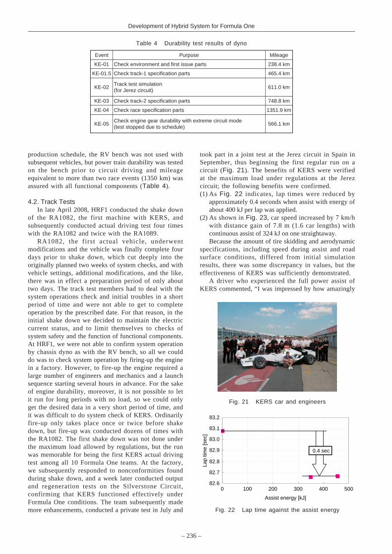
took part in a joint test at the Jerez circuit in Spain inSeptember, thus beginning the first regular run on acircuit (Fig. 21). The benefits of KERS were verifiedat the maximum load under regulations at the Jerezcircuit; the following benefits were confirmed.(1) As Fig. 22 indicates, lap times were reduced by
approximately 0.4 seconds when assist with energy ofabout 400 kJ per lap was applied.
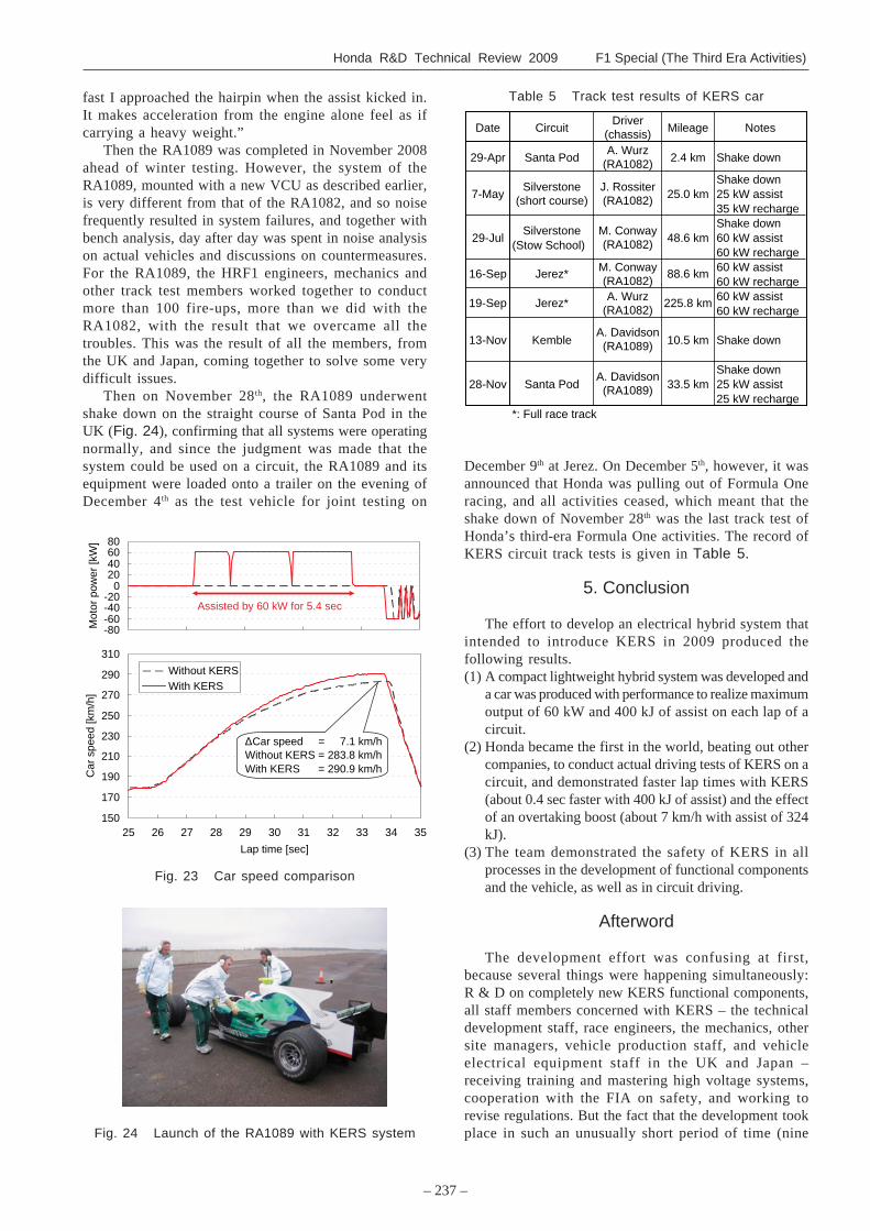
(2) As shown in Fig. 23, car speed increased by 7 km/hwith distance gain of 7.8 m (1.6 car lengths) withcontinuous assist of 324 kJ on one straightaway.Because the amount of tire skidding and aerodynamic
specifications, including speed during assist and roadsurface conditions, differed from initial simulationresults, there was some discrepancy in values, but theeffectiveness of KERS was sufficiently demonstrated.
A driver who experienced the full power assist ofKERS commented, “I was impressed by how amazingly
Fig. 21 KERS car and engineers
82.6
82.7
82.8
82.9
83.0
83.1
83.2
0 100 200 300 400 500
Assist energy [kJ]
Lap
time
[sec
]
0.4 sec
Fig. 22 Lap time against the assist energy
Event Purpose Mileage
KE-01 Check environment and first issue parts 238.4 km
KE-01.5 Check track-1 specification parts 465.4 km
Track test simulation�(for Jerez circuit)
KE-03 Check track-2 specification parts 748.8 km
KE-04 Check race specification parts 1351.9 km
Check engine gear durability with extreme circuit mode�(test stopped due to schedule)
KE-02 611.0 km
KE-05 566.1 km
Table 4 Durability test results of dyno
Honda R&D Technical Review 2009 F1 Special (The Third Era Activities)
– 237 –
fast I approached the hairpin when the assist kicked in.It makes acceleration from the engine alone feel as ifcarrying a heavy weight.”
Then the RA1089 was completed in November 2008ahead of winter testing. However, the system of theRA1089, mounted with a new VCU as described earlier,is very different from that of the RA1082, and so noisefrequently resulted in system failures, and together withbench analysis, day after day was spent in noise analysison actual vehicles and discussions on countermeasures.For the RA1089, the HRF1 engineers, mechanics andother track test members worked together to conductmore than 100 fire-ups, more than we did with theRA1082, with the result that we overcame all thetroubles. This was the result of all the members, fromthe UK and Japan, coming together to solve some verydifficult issues.
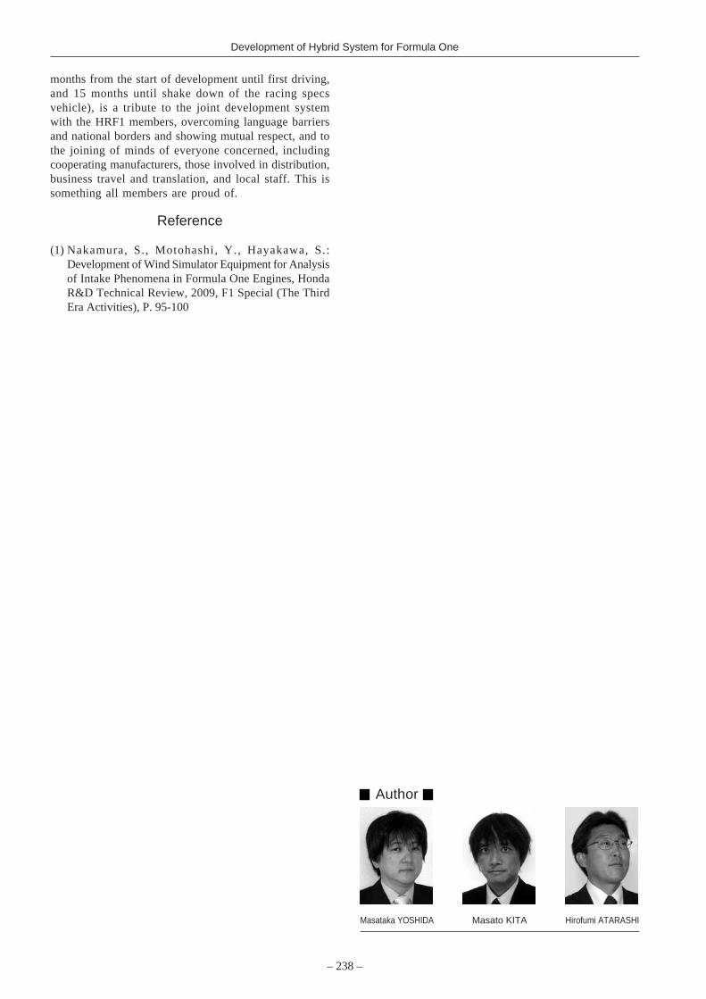
Then on November 28th, the RA1089 underwentshake down on the straight course of Santa Pod in theUK (Fig. 24), confirming that all systems were operatingnormally, and since the judgment was made that thesystem could be used on a circuit, the RA1089 and itsequipment were loaded onto a trailer on the evening ofDecember 4th as the test vehicle for joint testing on
Fig. 24 Launch of the RA1089 with KERS system
Table 5 Track test results of KERS car
Date CircuitDriver�
(chassis) Mileage Notes
29-Apr Santa PodA. Wurz�
(RA1082) 2.4 km Shake down
7-MaySilverstone�
(short course)J. Rossiter�(RA1082) 25.0 km
Shake down25 kW assist35 kW recharge
29-JulSilverstone
(Stow School)M. Conway�(RA1082) 48.6 km
Shake down60 kW assist60 kW recharge
M. Conway�(RA1082)
60 kW assist60 kW recharge
A. Wurz�(RA1082)
60 kW assist60 kW recharge
13-Nov KembleA. Davidson�(RA1089) 10.5 km Shake down
28-Nov Santa PodA. Davidson�(RA1089) 33.5 km
Shake down25 kW assist25 kW recharge
*: Full race track
16-Sep Jerez* 88.6 km
19-Sep Jerez* 225.8 km
December 9th at Jerez. On December 5th, however, it wasannounced that Honda was pulling out of Formula Oneracing, and all activities ceased, which meant that theshake down of November 28th was the last track test ofHonda’s third-era Formula One activities. The record ofKERS circuit track tests is given in Table 5.
5. Conclusion
The effort to develop an electrical hybrid system thatintended to introduce KERS in 2009 produced thefollowing results.(1) A compact lightweight hybrid system was developed and
a car was produced with performance to realize maximumoutput of 60 kW and 400 kJ of assist on each lap of acircuit.
(2) Honda became the first in the world, beating out othercompanies, to conduct actual driving tests of KERS on acircuit, and demonstrated faster lap times with KERS(about 0.4 sec faster with 400 kJ of assist) and the effectof an overtaking boost (about 7 km/h with assist of 324kJ).
(3) The team demonstrated the safety of KERS in allprocesses in the development of functional componentsand the vehicle, as well as in circuit driving.
Afterword
The development effort was confusing at first,because several things were happening simultaneously:R & D on completely new KERS functional components,all staff members concerned with KERS – the technicaldevelopment staff, race engineers, the mechanics, othersite managers, vehicle production staff, and vehicleelectrical equipment staff in the UK and Japan –receiving training and mastering high voltage systems,cooperation with the FIA on safety, and working torevise regulations. But the fact that the development tookplace in such an unusually short period of time (nine
-80�-60�-40�-20�
0�20�40�60�80�
Mot
or p
ower
[kW
]�
150�
170�
190�
210�
230�
250�
270�
290�
310�
25� 28� 29� 30� 31� 32� 33� 34� 35�27�26�
Lap time [sec]�
Car
spe
ed [k
m/h
]�
Without KERS�With KERS�
Assisted by 60 kW for 5.4 sec�
Car speed = 7.1 km/h�Without KERS = 283.8 km/h�With KERS = 290.9 km/h�
Fig. 23 Car speed comparison
– 238 –
Development of Hybrid System for Formula One
Masataka YOSHIDA Masato KITA
Author
Hirofumi ATARASHI
months from the start of development until first driving,and 15 months until shake down of the racing specsvehicle), is a tribute to the joint development systemwith the HRF1 members, overcoming language barriersand national borders and showing mutual respect, and tothe joining of minds of everyone concerned, includingcooperating manufacturers, those involved in distribution,business travel and translation, and local staff. This issomething all members are proud of.
Reference
(1) Nakamura, S., Motohashi, Y., Hayakawa, S.:Development of Wind Simulator Equipment for Analysisof Intake Phenomena in Formula One Engines, HondaR&D Technical Review, 2009, F1 Special (The ThirdEra Activities), P. 95-100