Embed Size (px)
Citation preview
99
Sakurai et al.: High Productive Micro Solder Flip Chip Bonding Process (1/8)
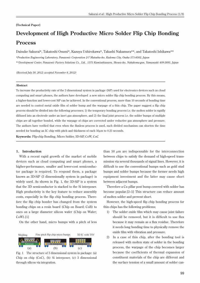
Fig. 1 The structure of 3 dimensional system in package: (a) Chip on chip (CoC), (b) Si interposer, (c) 3 dimensional through silicon via integration.
1. IntroductionWith a recent rapid growth of the market of mobile
devices such as cloud computing and smart phones, a
higher-performance, smaller and lower-cost semiconduc-
tor package is required. To respond them, a package
known as 3D-SiP (3 dimensionally system in package) is
widely used. As shown in Fig. 1, the 3D-SiP is a system
that the 3D semiconductor is stacked to the Si interposer.
High productivity is the key feature to reduce assembly
costs, especially in the flip chip bonding process. There-
fore the flip chip bonder has changed from the system
bonding chips on a resin board (Chip on Board; CoB) to
ones on a large diameter silicon wafer (Chip on Wafer;
CoW).[1]
On the other hand, micro bumps with a pitch of less
than 50 μm are indispensable for the interconnection
between chips to satisfy the demand of high-speed trans-
mission via several thousands of signal lines. However, it is
difficult to use the conventional bumps such as gold stud
bumps and solder bumps because the former needs high
equipment investment and the latter may cause short
between adjacent bumps.
Therefore a Cu pillar post bump covered with solder has
become popular.[2–5] This structure can reduce amount
of molten solder and prevent short.
However, the high-speed flip chip bonding process for
thin chips has the following problems;
1) The solder oxide film which may cause joint failure
should be removed, but it is difficult to use flux
because it may remain as a flux residue. Therefore
it needs long bonding time to physically remove the
oxide film with vibration and pressure.
2) In a case of thin chip, after the bonding tool is
released with molten state of solder in the bonding
process, the warpage of the chip becomes larger
because the coefficients of thermal expansion of
constituent materials of the chip are different and
the surface tension of a small amount of solder can-
[Technical Paper]
Development of High Productive Micro Solder Flip Chip Bonding
ProcessDaisuke Sakurai*, Takatoshi Osumi*, Kazuya Ushirokawa*, Takashi Nakamura**, and Takatoshi Ishikawa**
*Production Engineering Laboratory, Panasonic Corporation 2-7 Matsuba-cho, Kadoma City, Osaka 571-8502, Japan
**Development Center, Panasonic Factory Solutions Co., Ltd., 1375 Kamisukiawara, Showa-cho, Nakakoma-gun, Yamanashi 409-3895, Japan
(Received July 30, 2012; accepted November 8, 2012)
Abstract
To increase the productivity rate of the 3 dimensional system in package (SiP) used for electronics devices such as cloud
computing and smart phones, the authors have developed a new micro solder flip chip bonding process. By this means,
a higher-function and lower-cost SiP can be achieved. In the conventional process, more than 10 seconds of bonding time
are needed to control metal oxide film of solder bump and the warpage of a thin chip. The paper suggest a flip chip
process should be divided into the following processes; 1) the temporary bonding process i.e. the molten solder is rapidly
diffused into an electrode under an inert gas atmosphere, and 2) the final joint process i.e. the solder bumps of multiple
chips are all together bonded, while the warpage of chips are corrected under reductive gas atmosphere and pressure.
The authors have verified that even when the fluxless process is used, such divided mechanism can shorten the time
needed for bonding an IC chip with pitch and thickness of each 50μm to 0.25 seconds.
Keywords: Flip-chip Bonding, Micro Solder, 3D-SiP, CoW, CoC

100
Transactions of The Japan Institute of Electronics Packaging Vol. 5, No. 1, 2012
not absorb the warpage. As the result, an open fail-
ure in the joint part occurs and thus it needs long
time to cool the solder joint down under pressure
until it solidifies.
For these reasons, more than 10s is needed to bond a
chip in the conventional way.
To solve these issues, the authors have developed a new
high-producing-flip-chip-bonding-process controlling the
solder oxide film and the warpage of the chip. This study
describes the newly developed micro solder flip-chip bond-
ing process which can shorten the bonding time from 10s
to 0.25 seconds, corresponding with a thin chip (50 μm
thick) with a pitch of 50 μm for 3D-SiP.
2. Establishment of Divided Micro Solder Flip Chip Bonding Process for High Productivity2.1 Divided micro solder flip chip bonding process
To realize high productivity, the authors suggest that a
micro solder flip chip bonding process should be divided
into two processes consisting of the temporary bonding
process for pursuing a high speed bonding and the final
bonding process for ensuring the reliability. This process
is defined as the divided flip chip bonding process which
enables a high speed bonding.
Figure 2 shows an example of the bonding process for
3D-SiP by using the divided bonding process.
a) Firstly, the heated first layer of a 3D stack chip is
bonded to a wafer with a high speed bonder. This
process is defined as the temporary bonding pro-
cess purposed to reduce the warpage of a chip
under the stackable level. In this process, the solder
nearby the electrode pad should be partially alloyed
and the solder able to remelt should be remained.
b) Next, the second layer of the 3D stack chip is tem-
porary bonded one by one in the same way as the
first layer. Over the third layer the temporary bond-
ing is repeated. Since the solder remained in the
joint of the lower layer of the chip remelts and
absorbs the warpage of the chips and the variation
in the height of the chips, it becomes easier to stack
chips.
c) Finally, multiple stacked chips are pressed by heat
on whole set of a wafer until all pins of solder joint
become intermetallic compound (IMC) in order to
ensure the electric continuity between chips. The
time needed for this process doesn’t affect the pro-
duction lead time because of batch processing.
Moreover, clearances between the stacked chips
are sealed with under-fill resin.
2.2 Micro-bumping technology for CoWIt is considered that the solder capped Cu pillar bumps
should be used as the micro bumps on the surface side of
chip. Electroless nickel immersion gold plating, in our
opinion, is one of the best ways to be used as the bumps on
the wafer and on the back side of the top chip. It is because
of three reasons. One is because no remolten process is
needed during the wafer is being laid on the heated stage.
The second one is because the back-side of the bumps
directly touches the high-temperature bonding head. The
other one is because no exposure masks and no big spaces
for production lines are needed.
2.3 Flux-less high speed temporary bonding pro-cess for thin chips
The authors have considered that the surface of solder
should be controlled and that the molten solder should be
rapidly diffused into the Ni electrode for high speed bond-
ing. Especially, the authors have focused on the conchoi-
dal Ni3Sn4 phase on the electrode.[6] If the solder wets
and the IMC is formed allover the electrode, it is consid-
ered that wetting force of solder should reduce the warp-
age of a chip even after the bonding tool is released. This
is why the paper has studied the effects of plasma cleaning
process and the influence of the diameter of wetting area
on the interconnection in temporary bonding process.
2.4 Final bonding processThe final bonding process has 2 purposes. One is to
assure the electric continuity between all interconnection
pins and the other is to reduce the warpage of a chip less
than that after temporary-bonding. To assure the electric
continuity, the authors have considered the oxide film
which is formed after temporary bonding process should
be removed by reductive gas, which penetrates into a nar-
row clearance between the top and bottom chips. The
authors suggest the final bonding process as follows.
Firstly, SiPs after temporary-bonding process are put
inside a batch chamber. After reducing a pressure to a vac-
Fig. 2 The divided micro solder bonding process; (a) tempo-rary-bonding process for chip to wafer, (b) temporary-bond-ing process for stacking chips, (c) final bonding process.

101
Sakurai et al.: High Productive Micro Solder Flip Chip Bonding Process (3/8)
uum, they are heated inside the chamber containing
reductive gas. The function of reductive gas is as same as
flux.[7] When temperature of solder rises over a boiling
point of reductive gas, the tin oxide starts to be reduced.
After that, when it reaches over the solder melting point,
the unmolten solder joints after temporary-bonding are
molten and transformed into IMC.
Moreover, to correct the warpage of chip, the authors
have considered the bonding pressure should be needed.
Therefore the paper has studied the necessity for the
reductive gas and bonding pressure in the final bonding
process.
This discussion in the paper is focused on the develop-
ment of the flux-less high speed temporary bonding pro-
cess for thin chips and the development of a batch final
bonding process to assure the joint quality.
3. Experimental Method3.1 Test vehicle structure
Table 1 shows a specification of test vehicle. The evalu-
ated structure is CoC (chip on chip). A 50 μm-thick chip is
bonded to the underneath chip having thickness of 775 μm
thick. Both chips are interconnected with 5,184 micro-
bumps placed in 72 rows and 72 columns with a pitch of 50
μm. The interconnection has 4 daisy chains. The number
of pins in a daisy chain is 1,296.
3.2 The test vehicle fabrication processFigure 3 shows a fabrication process of the test vehicle.
Firstly, the surface of the bumps of both chips is cleaned
by Ar plasma of the plasma cleaner in order to remove the
solder oxide film and organic contamination formed in the
micro-bumping process. Next, the top chip (see Fig. 3(a))
was temporary-bonded by heat on the bottom chip align-
ing the bump position. A 300 mm-wafer-supported flip chip
bonder is used in this process to achieve bonding accuracy
of ± 3 μm/3σ. The temporary-bonded CoC is then final-
bonded by heat press under reductive gas with a batch
vacuum reflow oven. Formic acid gas, which boiling point
is 373 K, was used as reductive gas. Figure 4 shows a ther-
mal profile of the interconnection in the process.
3.3 Evaluation item1) The validity of plasma cleaning on the surface of
solder
The surface of solder bump was analyzed by Auger anal-
ysis. The thickness of the tin oxidation film was compared
the plasma-cleaned bump to the untreated one. Moreover,
the authors have compared the bonding status of the
cleaned chip to that of the untreated chip. The bonding
status is observed by X-ray.
2) The status of interconnection after temporary-bond-
ing
The height of the curved chip was measured in the 3.5 ×
3.5 mm area with 3 dimensional laser displacement meter.
The authors define the difference between the maximum
height of the curved chip from the reference plane and the
minimum height of that as the warpage. To catch the phe-
Table 1 Specifications of the test vehicle.
Fig. 3 The cross-sectional illustration of interconnection in fabrication process of the test vehicle: (a) plasma cleaning, (b) temporary-bonding, (c) final bonding.
Fig. 4 Temperature profile in the final bonding process.

102
Transactions of The Japan Institute of Electronics Packaging Vol. 5, No. 1, 2012
nomenon clearly, chips with larger initial warpage have
been used. The initial warpage is +7 μm at 303 K and +25
μm at 443 K when the bump formed side of the top chip is
plus direction. After the chip was bonded on the bottom
chip, the warpage of the top chip of a CoC was evaluated
by the same way.
The cross-sectional interconnection image was observed
by SEM in the position of the maximum joint clearance in
a chip and analyzed by EDX. The diameter of wetting area
which is observed in the cross-sectional image is defined
as the diameter of wetting area. The paper has studied
about the 5 cases of the diameter of wetting area; (a) 0, (b)
4.5, (c) 9.7, (d) 13.7 and (e) 16.7 μm. These test vehicles
were fabricated by the bonding time of 0.25 seconds. Each
bonding pressure was (a) 2.9, (b) 0.6, (c) 2.9, (d) 50 and
(e) 9.6 mN/pin.
The electric resistance of interconnection was also mea-
sured. The increased electric resistance of interconnection
is calculated as the following formula. The theoretical elec-
tric resistance of interconnection is calculated by shape
and specific resistance of interconnection.
(the increased electric resistance of interconnection) =
(the measured chain resistance) /
(the number of pins) –
(the theoretical electric resistance of interconnection)
3) The status of interconnection after final bonding
For this study, the warpage, the interconnection status
and the electric interconnection as same as temporary
bonding were evaluated. The temporary-bonded CoC
package was fabricated by the bonding time of 0.25 sec-
onds and the bonding pressure was 2.9 mN/pin. The top
chip of the package curved 12.6 μm in concave shape
when viewed from the back side of the top chip.
To verify the necessity of reductive gas, the status of
interconnection under formic acid gas is compared with
the one under nitrogen gas. Moreover, the necessity of
bonding pressure is verified comparing with two condi-
tions; 2.3 and 25.7 μN/pin.
4. Results and Discussion4.1 Validity study of plasma cleaning on surface of solder
Figure 5 shows the effect of plasma cleaning on the sur-
face of a bump. It is observed that the thickness of tin
oxide film (shown as ‘O’ ) ranges from 25 to 65 nm before
the plasma cleaning and it decreases to less than 1 nm
after the plasma cleaning process.
Figure 6 shows the effect of plasma cleaning on the
X-ray image of interconnection after temporary-bonding.
When the bump is cleaned, it is observed that all intercon-
nections have a smooth surface and uniform shape. In con-
trast, without plasma cleaning, most of the interconnection
has an uneven surface and its shape varies widely. These
results indicate the high efficacy of Ar plasma cleaning.
4.2 Influence of diameter of wetting area on inter-connection in temporary bonding process
Figure 7 shows the cross-sectional photos of the inter-
connections after the temporary-bonding. It is observed
that the Sn-2.3 Ag solder connects to the Cu pillar on the
top with the Ni electrode on the bottom chip. The EDX
analysis result of interconnection is shown in Fig. 7(c)’. It
is observed that a Cu3Sn layer is formed on the Cu pillar
and that a Cu6Sn5 layer is formed on it and that about 1 μm
thick IMC Ni3Sn4 phase is formed in between the Ni and
Sn interface.
Figure 8 shows the relationship between the diameter of
wetting area and the warpage of the top chip after tempo-
rary-bonding. Without a wetting area, the warpage is 8 μm.
Along with the increase in the diameter of wetting area,
the warpage becomes smaller. When the diameter grows
more than 10 μm, the warpage is reduced less than 4 μm.
Figure 9 shows the influence of the diameter of wetting
area on the increased interconnection resistance. Without
Fig. 5 The effect of plasma cleaning on the surface of a bump: (a) before plasma cleaning, (b) after plasma cleaning.
Fig. 6 The effect of plasma cleaning on the X-ray image of interconnection after temporary-bonding: (a) before plasma cleaning, (b) after plasma cleaning.

103
Sakurai et al.: High Productive Micro Solder Flip Chip Bonding Process (5/8)
wetting, an open failure occurs. As the diameter of wetting
area is larger, the increased interconnection resistance
becomes lower. When the diameter of wetting area is over
13 μm, it falls within 25 mΩ/pin.
It is considered these phenomena to be caused by the
following mechanism. Firstly, when the top chip is
chucked on the bonding head, the solder on the Cu pillar
is molten state as shown in Fig. 10 (a). Next, the molten
solder touches the flat surface of the Ni electrode and is
compressed by the bonding force as shown in Fig. 10 (b).
The diameter of wetting area is dependent on quantity of
heating and bonding pressure. While the IMC is formed
on a part of the surface of the Ni electrode by insufficient
quantity of heating, it’s formed allover the Ni electrode
with sufficient heating. When the bonding head is released
from the top chip, the molten solder is vertically stretched
according to the warpage of the chip. After that, as soon as
it’s cooled down to its solidification point, the joint shape is
Fig. 7 The cross-sectional SEM images of solder joints after temporary bonding: each diameter of wetting area is (a) 0, (b) 4.5, (c) 9.7, (d) 13.7, (e) 16.7 μm. The image (c)’ is an enlarged image of (c).
Fig. 8 Relationship between the diameter of wetting area and the warpage of the top chip after temporary bonding.
Fig. 9 The influence of the diameter of wetting area on the increased interconnection resistance after temporary bond-ing.
Fig. 10 The cross-sectional illustration of the warpage con-trol mechanism: (a) before touching the Ni electrode, (b) in temporary-bonding, (c) when chip is released from the tool.

104
Transactions of The Japan Institute of Electronics Packaging Vol. 5, No. 1, 2012
determined (see Fig. 10 (c)).
The paper discusses about the force of the interface
between solder and the electrode immediately before the
time of solidification of solder. The force which is stretched
upward by the warpage of the chip works at the interface
shown as ‘F1’ in Fig. 10 (c). The solder-wetting force works
downward shown as ‘F2’ in the same figure. The force F2
is proportional to the wetting area on the electrode. If F1 is
much larger than F2 immediately before the time of solder
solidification, it is considered that the molten solder would
be broken, that the warpage would become larger, and that
an open would occur. If F1 balances F2 immediately before
the time of solder solidification, it is considered that the
shape of the molten solder would be determined by the
diameter of wetting area. Therefore it is considered that,
when the wetting area is max, the molten solder would be
compressed most so that the warpage of the top chip
would become lowest.
This is why the authors conclude that the warpage of a
50 μm thick chip can be reduced lower than 4 μm even if
the temporary-bonding time is only 0.25 seconds.
4.3 Verification of the necessity of reductive gas in final bonding process
Figure 11 shows the cross-sectional photos of the inter-
connections after the final bonding process. Figures. 11
(c) and (d) show the cross-sectional interconnection image
comparing nitrogen gas and reductive gas in the final
bonding process. As shown in Fig. 11 (d), under nitrogen
gas atmosphere, voids are observed between the Ni elec-
trode and the solder. In contrast, under reductive gas
atmosphere, the solder wets the Ni electrode well as
shown in Fig. 11 (c).
EDX analysis shows that the interconnection composi-
tion is 54.3at%Cu-3.1at%Ni-42.6at%Sn under N2 gas atmo-
sphere and that it is 52.4at%Cu-4.5at%Ni-43.1at%Sn under
reductive gas. Judging from the phase diagram, it is con-
sidered that both of the interconnections are consist of
(Cu,Ni)6Sn5.[8]
The authors consider these results to be caused by the
following mechanism. In the temporary-bonding process,
the voids are already made because a part of the solder
does not spread on the electrode, and the oxide film is
formed on the surface of solder around voids. When the
nitrogen gas is used in the final bonding process, the oxide
film inside the molten solder remains because the voids do
not flow. In contrast, under reductive gas the voids
becomes easily pushed outside of the solder and spreads
allover the electrode because the reductive gas increases
the fluidity of the molten solder.
These results indicate the efficiency of reductive gas.
4.4 Verification of the necessity of bonding pres-sure in final bonding process
In the case of 2.3 and 25.7 μN/pin, the warpage of the
chip after final bonding is 17.4 μm and 9.2 μm. This result
Fig. 11 The cross-sectional SEM images of interconnections: (a) after tem-porary bonding, (b) pressure: 2.3 μN/pin, under reductive gas atmosphere, (c) pressure: 25.7 μN/pin, under reductive gas atmosphere, (d) pressure: 25.7 μN/pin, under nitrogen gas atmosphere. The images of (b), (c), (d) are after final bonding.

105
Sakurai et al.: High Productive Micro Solder Flip Chip Bonding Process (7/8)
shows that the warpage becomes larger than after tempo-
rary bonding in lower bonding pressure and that it
becomes smaller in higher bonding pressure.
In the case of 2.3 μN/pin, an open has occurred. In con-
trast, in the case of 25.7 μN/pin, the increased intercon-
nection resistance is within +3 mΩ/pin.
After temporary-bonding, the solder height is 9.3 μm as
shown in Fig. 11 (a). While it increases to 10.7 μm in the
case of 2.3 μN/pin (see Fig. 11 (b)), it decreases to 5.4 μm
in the case of 25.7 μN/pin (see Fig. 11 (c)).
The authors discuss about the final bonding mechanism
as follows. While the solder in interconnections remelts,
the top chip begins to curve by the heat stress induced in
the difference of the co-efficient of inner wiring layers and
Si substrate and move upward. When the bonding pres-
sure is lower than the heat stress of the chip, the molten
solder is stretched and the warpage becomes larger than
after temporary-bonding. On the other hand, when the
bonding pressure is higher than the heat stress of the
chip, the molten solder is compressed and the warpage
decreases.
This is the reason why the authors conclude the bond-
ing pressure is needed for thin chips during the final bond-
ing process.
5. ConclusionsThe authors have developed a new flip chip bonding pro-
cess for the 3D system in package (SiP). The new feature
of this process is the separation of the process into two i.e.
the temporary-bonding and the batch final-bonding pro-
cess. In the former process, the solder is rapidly diffused
into the electrode on the bottom chip and in the latter pro-
cess the chips are all together pressed inside a vacuum
chamber containing reductive gas. By using this newly-
developed process, a very thin chip can even be produced
in a short time. For example, when a 50 μm-thick chip with
a pitch of 50 μm has been used, it is found that the tempo-
rary-bonding time is shorten from 10 seconds to 0.25 sec-
onds. In the near future, the application of this process to
the chip on wafer with stacked chips will be our next study.
References[1] “Assembly and Packaging,” International Technology
Roadmap for Semiconductors, pp. 22–27, 2009.
[2] T. F. Yang, K. S. Kao, R. C. Chen, J. Y. Chang, and C. J.
Zhan, “Development of Wafer-Level Underfill Bond-
ing Process for 3D Chip Stacking,” ICEP2011 Pro-
ceedings, pp. 74–81, 2011.
[3] H. Noma, Y. Oyama, H. Nishiwaki, M. Takami, T.
Takatani, K. Toriyama, and Y. Orii, “Wettability and
Reliability for Double-Sided Assembly with Chip Con-
nection (C2) Flip-Chip Technology,” Transaction of
The Japan Institute of Electronics Packaging, Vol. 2,
No. 1, pp. 85–90, 2009.
[4] B. A. Appelt, T. H. Wang, Y. S. Lai, and H. Chung,
“Next Generation fcCSP Packaging,” ICEP2011 Pro-
ceedings, pp. 426–439, 2011.
[5] M. Ishida, Y. Orii, K. Sakuma, and F. Yamada, “Pro-
spective Flip Chip Assembly Technology in Semicon-
ductor Package,” Journal of the Japan Institute of
Electronics Packaging, Vol. 12, No. 4, pp. 292–300,
2009.
[6] C. W. Hwang, K. S. Kim, and K. Suganuma, “Inter-
faces in Lead-free Soldering,” Journal of Electronic
Materials, Vol. 32, No. 11, pp. 1249–1256, 2004.
[7] The Japan Welding Engineering Society, “Standard
Micro Soldering Technology,” pp. 43–50, Nikkan
Kogyo Shinbun Ltd., 1992.
[8] C. W. Hwang, K. Suganuma, M. Kiso, and S.
Hashimoto, “Influence of Cu Addition to Interface
Microstructure between Sn-Ag Solder and Au/Ni-6P
Plating,” Journal of Electronic Materials, Vol. 33, No.
10, pp. 1200–1209, 2004.

106
Transactions of The Japan Institute of Electronics Packaging Vol. 5, No. 1, 2012
Daisuke SakuraiDivision of manufacturing science, graduate school of engineering, Osaka University completed in 1999. Master degree of engi-neering.Currently working for production engineer-ing laboratory, Panasonic.
Takatoshi OsumiDivision of manufacturing science, graduate school of engineering, Osaka University completed in 2002. Master degree of engi-neering.Currently working for production engineer-ing laboratory, Panasonic.
Kazuya UshirokawaKinki UniversityBachelor of electrical engineering, March, 1995Currently working for production engineer-ing laboratory, Panasonic.
Takashi NakamuraTokyo Institute of TechnologyMaster of nuclear engineering, March, 1996Panasonic Factory Solutions Co., LtdDevelopment Center, Present
Takatoshi IshikawaFukuoka UniversityMaster of science, March, 1984Panasonic Factory Solutions Co., LtdDevelopment Center, Present