Embed Size (px)
Citation preview
1
Development of high performance lightweight aluminum alloy/SiC hollow sphere syntactic foams and
compressive characterization at quasi-static and high strain rates
Dung D. Luong1, Oliver M. Strbik III
2, Vincent H. Hammond
3, Nikhil Gupta
1,*, and Kyu Cho
3
1Composite Materials and Mechanics Laboratory, Department of Mechanical and Aerospace Engineering,
Polytechnic Institute of New York University, Brooklyn, NY 11201 USA
2Deep Springs Technology, LLC, 4750 W. Bancroft St., Suite 5, Toledo, OH 43615 USA
3U.S. Army Research Laboratory, Weapons and Materials Research Directorate, Aberdeen Proving Ground, MD
21005 USA
ABSTRACT
Aluminum alloy A356 filled with silicon carbide hollow spheres (SiCHS) is investigated for quasi-static
(10-3
s-1
) and high strain rate (up to 1520 s-1
) compressive properties. Such closed cell composite foams, called
syntactic foams, are of interest in weight sensitive structural applications. The present work is focused on
understanding the compressive failure mechanism and relating them with the material microstructure. The
compressive and plateau strengths of syntactic foams with SiCHS are found to be 163 and 110 MPa, respectively.
The measured properties are considerably higher than the existing fly ash cenosphere filled aluminum matrix
syntactic foams. Compressive failure mechanisms are studied for A356/SiCHS syntactic foams and direct evidence
of hollow sphere crushing at the end of the elastic regions is obtained. The predictions of compressive strength
obtained from an existing model are validated with the experimental results. Extensive analysis of data on open and
closed cell foams containing gas porosity and syntactic foams is presented. A clear advantage in terms of low
density and high yield strength is observed in A356/SiCHS syntactic foams compared to other foams. Yield strength
of aluminum foams may be different at high strain rate compression compared to quasi-static values but most of the
foams do not show strong evidence of strain rate sensitivity within the high strain rate regime.
Keywords: Metal-matrix composites (MMCs) (A); Mechanical properties (C); Porosity (C); Metallography
(D).
* Corresponding author. Ph: +1-718-260 3080, Fax: +1-718-260 3532, Email: [email protected]

2
1 INTRODUCTION
Aluminum/SiC is one of the most widely studied aluminum matrix composite (AMC) systems. Aluminum
alloys and AMCs have been used to replace steel in automotive body panels, engine components, and brake rotors to
reduce structural weight, which has resulted in increased interest in these materials. Particles, whiskers, short fibers,
and continuous fibers of SiC have been used as reinforcements in AMCs [1-3]. Typically, the cost of reinforcement
increases with the aspect ratio. Therefore, interest in SiC particles (SiCp) has been very high for strengthening
aluminum alloys [4, 5].
Lightweight composites are attracting a great deal of attention due to the possibility of weight saving in
industrial applications [6]. Automobile weight reduction can directly translate into reduced fuel consumption.
Reduction in the weight of aircraft and marine vessels can lead to increased loading capacity. Motivated by these
applications, open and closed-cell metal foams of different densities, cell sizes, and materials have been studied [7,
8]. Open-cell foams comprise interconnected pores, whereas closed-cell foams have each pore separate. A class of
closed-cell foams synthesized by incorporating hollow particles in the matrix is called syntactic foams. The density
of syntactic foams is higher than that of open and closed-cell foams at the same level of porosity. However, they
also have higher modulus and strength. In structural applications where a certain level of modulus and strength are
required for load bearing capacity, syntactic foams present an option to replace higher density materials. Polymer
and metal matrix syntactic foams show a general trend in which the enhancement in strength or modulus is
associated with an undesired penalty in the foam density [9, 10]. If SiCHS lead to development of syntactic foams
with high mechanical properties at low density, then the weight savings in load bearing structural applications can
be realized.
Numerous reports on a variety of metal matrix syntactic foams can be found in existing literature. A review
article provides details on the synthesis methods and mechanical properties such as modulus, yield strength, and
peak compressive strength observed in syntactic foams [10]. This review shows that most of the existing studies
have used glass or fly ash particles as hollow fillers in aluminum, titanium, and magnesium alloy matrices. Selection
of constituent materials is an important part of designing syntactic foams, where strength, modulus as well as density
can be optimized. A clear advantage is observed in the compressive properties and density of aluminum and
magnesium alloy syntactic foams compared to the titanium matrix syntactic foams. Among available hollow
particles, fly ash cenospheres are widely used as fillers in syntactic foams because of their low cost and abundant

3
availability [11-14]. Cenospheres are not manufactured in an optimized synthesis environment and their structure
and properties vary over a wide range, which is also reflected in the properties of syntactic foams. Therefore, for
high performance applications, it is preferred to use high quality engineered hollow particles in synthesizing
syntactic foams. The benefits of using such particles would be justified in the improved mechanical properties of the
resulting syntactic foams. The present work is aimed at exploring the possibility of using SiC hollow spheres
(SiCHS) for development of high performance syntactic foams.
In this work SiC hollow sphere filled A356 matrix syntactic foams are developed and characterized for
quasi-static and dynamic compressive properties. High strain rate (HSR) properties of a variety of aluminum foams
have been studied by several groups but studies related to syntactic foams are scarce [15]. The mechanical properties
of A356/SiCHS syntactic foams are compared with properties of several existing syntactic foam systems to determine
the benefits of using SiC hollow spheres compared to other types of particles. Literature data are analyzed for a
variety of aluminum foams to understand the trends obtained for strain rate sensitivity.
2 MATERIALS AND METHODS
2.1 Materials
The SiCHS were manufactured by Deep Springs Technology (Toledo, OH). These particles have nominal
diameter and wall thickness of 1 mm and 70 µm, respectively. The SiCHS shape and size can be visualized in Fig. 1a.
A broken particle is shown in Fig. 1b, where the wall thickness of the hollow sphere can be observed. The wall
thickness may vary within a sphere. The densities of SiC and SiCHS are 3150 and 1160 kg/m3, respectively. A356
matrix syntactic foams filled with 60 vol.% SiCHS were synthesized using a pressure infiltration method [16]. The
specimens did not have any measurable porosity in the matrix, which was confirmed by extensive microscopy.
Density of the synthesized syntactic foams was measured to be 1819±14 kg/m3. Size and weight of compression test
specimens were measured and used to calculate the specimen density.
2.2 Quasi-static compression
The quasi-static compression testing was conducted using an Instron 4469 test system equipped with a 50
kN load cell. Bluehill 2.0 software was used for acquisition of load and displacement data. A constant crosshead
displacement rate was maintained during the test to obtain an initial strain rate of 10-3
s-1
. Cylindrical specimens with

4
nominal diameter and length of 10 and 5 mm, respectively, were used for compression testing. To minimize the
effect of friction, 111 Valve Lubricant & Sealant (Dow Corning, Midland, MI) was used at contact surfaces between
the specimen and compression platens.
2.3 High strain rate compression
The HSR compression tests were conducted using a Split-Hopkinson pressure bar (SHPB) setup [17]. In
SHPB testing, the specimen is sandwiched between the incident and transmitter bars. The striker bar is launched to
impact the incident bar, which generates a stress pulse that propagates along the incident bar length. A brass pulse
shaper was used during the testing to obtain a constant rise time and strain plateau in the incident pulse. The
selection of pulse shaper was based on calibration studies. At the incident bar-specimen interface, the incident pulse
splits into the transmitted and reflected parts based on the impedance mismatch between the bar and the specimen
material. Similar phenomenon happens at the specimen-transmitter bar interface. The incident, reflected, and
transmitted pulses were acquired by two strain gauges of type CEA-13-240UZ-120 (Vishay Precision Group,
Melvern, PA) and then recorded by an oscilloscope Tektronix TDS 2014B (Beaverton, OR). The data was processed
using an in-house developed MatLab code based on existing theories for SHPB testing [17].
In this work, incident, transmitted, and striker bars of Inconel alloy were used. The Young’s modulus and
density of Inconel used in the calculations were 195 GPa and 8190 kg/m3, respectively. The elastic wave velocity in
Inconel at room temperature was taken as 4879 m/s. The length and diameter of the incident and transmitter bars
were 1.27 m and 12.7 cm, respectively. In SHPB testing the strain rate is not directly controlled during the test but is
recovered from the test results. Therefore, instead of testing multiple specimens at each strain rate, the results for all
specimens tested under HSR compression are reported. Cylindrical specimens of nominal 10 mm diameter and 5
mm thickness were used for testing.
2.4 Failure analysis
The microstructural observations were taken using a Nikon EPIPHOT 200 microscope fitted with a Nikon
DS-Fi1 digital camera and the images were acquired on the computer by NIS Elements 3.0 software. Standard
metallography procedures were applied for preparing specimens for optical microscopy.

5
A Nikon D7000 digital SLR camera with AF-S VR Micro-Nikkor 105mm f/2.8G IF-ED telephoto lens was
used for image acquisition during quasi-static compression. This macro lens is capable of taking high resolution
images of small objects with high depth of focus. In an optical microscope the depth of focus is small, which is
overcome in this digital camera arrangement at low magnifications.
Hitachi S-3400N scanning electron microscope (SEM) was used for surface imaging of specimens before
and after failure. The SEM is equipped with secondary electron (SE) and backscatter electron (BSE) detectors. The
SEM Specimens were sputter coated with gold before microscopy. An EDAX energy dispersive spectroscope (EDS)
is mounted on the microscope and the spectra are acquired and labeled using Gnensis software.
3 RESULTS
3.1 Microstructure
The microstructure of as-fabricated A356/SiCHS composite is shown in Fig. 2a and b at two different
magnifications. These optical micrographs show high survival rate of SiCHS in the matrix after the pressure
infiltration process. All the SiCHS visible in these figures are intact and are not infiltrated by the matrix. Fig. 2b
shows some closely spaced particles. A thin layer of matrix alloy can be clearly observed in the interparticle region
of closely spaced hollow spheres, which indicates good wetting at the matrix-sphere interface. Fig. 2c and d provide
further magnified views of the matrix-sphere interface. Intimate contact between matrix and particles at the interface
is observed in this figure, which can provide mechanical interlocking and result in high interfacial strength.
Previous studies have analyzed the interface in Al/SiCp composites [18, 19]. In these studies, a major
concern is the possible formation of Al4C3 at the interface. This brittle phase can lead to poor interfacial stress
transfer and is detrimental to the quality of the composite. Previous experimental results showed that in A356 alloy,
there is sufficient Si content to avoid formation of Al4C3 at the interface under appropriate processing conditions.
Although Al4C3 was not detected in the as-cast composites, heat treatment or prolonged exposure at high
temperature can result in the formation of Al4C3 [18]. Heat treatment conducted at 710C for 2 h led to Al4C3
formation [18]. Results of EDS analysis are shown in Fig. 3 for the as-cast A356/SiCHS specimens. The analysis on
the spheres showed dominant peaks for silicon and carbon and the analysis on the matrix prominently showed peaks
for aluminum and silicon. Oxygen was detected in both spectra. Carbon was not detected in the matrix, which
indicates that aluminum carbides have not formed in the matrix.
6
Fig. 2 shows that porosity is present inside the hollow spheres in the syntactic foams. The density of SiC
material (SiC ) and true particle density of hollow spheres (
HS ) can be used to calculate the porosity in syntactic
foams. The ratio of inner to outer radius of hollow spheres is defined as radius ratio (oi rr ). The radius ratio
relates to hollow sphere wall thickness as 1orw . The volume fraction of porosity in a hollow sphere can be
estimated as 3HS. Since the total hollow sphere volume fraction in the syntactic foam () is 0.6, the total
porosity in the syntactic foam slab is calculated as 36.0 v=0.38. The calculation shows that the syntactic
foams contain 38 vol.% porosity. This porosity will be available for compaction during compressive loading.
3.2 Compressive properties
3.2.1 Quasi-static compression
Quasi-static compressive stress-strain curves of A356/SiCHS syntactic foams are presented in Fig. 4. The
characteristics of these curves are similar to those previously observed for other metal and polymer matrix syntactic
foams [20-22]. The beneficial characteristic observed in the compressive behavior of syntactic foams is large
deformation strain, which is helpful in obtaining a high level of energy absorption in these materials. The quasi-
static compressive properties measured on five specimens of syntactic foams are presented in Table 1. In this table,
the compressive strength is defined as the peak stress at the end of the initial linear elastic region and plateau stress
is defined as the stress level after the initial drop. The stress plateau is not very stable in these specimens and an
increasing trend with small slope is seen. The reported value is calculated as the average from the start of the plateau
to the densification strain. The densification strain is defined as the strain in the plastic region where stress exceeds
the compressive strength value. The average values of compressive strength, plateau stress, and densification strain
are 163 MPa, 110 MPa and 0.46, respectively.
3.2.2 Dynamic compression
A representative set of incident and transmitter bar strain signals obtained from SHPB for the testing of
A356/SiCHS syntactic foams is shown in Fig. 5a. The reflected and transmitted strains are combined and compared
with incident pulse in Fig. 5b. A close matching between the two lines ensures that the losses are insignificant. This
strain response is converted to stress-strain and strain rate-strain graphs in Fig. 5c by

7
02 ltct rb
(1)
0AtAEt t
(2)
t
dt0
(3)
where A and E are the cross-section area and Young’s modulus of the bar materials, respectively, and cb is the sound
wave velocity in the bar. In addition, l0 and A0 are the initial length and cross-section area of the specimen,
respectively, r(t) and t(t) are the reflected and transmitted axial strain pulses with respect to time, respectively, and
is a time variable used for integration.
The majority of the stress-strain graph in Fig. 5c is obtained under an average high strain rate of 970 s-1
.
The general trend of dynamic stress-strain graphs is similar to quasi-static compression graphs, where a linear elastic
region is followed by drop in stress after the peak strength is reached. It should be noted that the strain in dynamic
testing is limited to the pulse width observed in Fig. 5c, which is dependent on the striker bar length. Therefore,
densification strain is not obtained in dynamic stress-strain graphs. The calculated dynamic mechanical properties
are presented in Table 2. The modulus data should be treated with caution in SHPB testing. Fig. 5c shows that the
strain rate rises sharply in the initial part of the stress-strain curve. This part is avoided during modulus calculation
and only the region that corresponds to constant strain rate is used for calculation. If the constant strain rate region is
not obtained until the peak stress is reached, the modulus cannot be calculated in this kind of testing.
A comparison of quasi-static and dynamic properties in Table 1 and Table 2, respectively, shows that the
compressive properties of A356/SiCHS syntactic foams are not strain rate sensitive. The peak strength value obtained
from the dynamic test is 123.5±3.8 MPa. These results are qualitatively similar to observations on cp-Al/cenosphere
syntactic foams, where no strain rate sensitivity was observed in the HSR range [23]. Several types of open and
closed cell aluminum foams are found to be strain rate insensitive [15, 24]. As the strain rate sensitivity is dependent
on strain rate [25], the present conclusions are limited to the strain rate range used in this work.
3.3 Failure analysis
The microstructure of as-fabricated specimens obtained from the SEM is presented in Fig. 6. Uniformity in
the SiCHS distribution can be seen in this figure. A closer observation shows that cracks exist in some of the SiCHS

8
particles (Fig. 7), which may have occurred during composite fabrication. These micrographs of as-fabricated
materials will be useful in understanding the failure mechanisms.
The failure pattern in syntactic foams was observed using a high resolution digital camera equipped with a
telephoto lens. Fig. 8 illustrates a quasi-static compressive stress-strain diagram of A356/SiCHS syntactic foams. Six
locations corresponding to various optical photographic observations captured in Fig. 9 are identified in this figure.
The specimen before starting the test is shown in Fig. 9a. During the elastic deformation, no SiCHS failure is
observed, as seen in Fig. 9b. As the stress peak is reached, SiCHS failure starts, as captured in the hollow sphere
marked by a circle in Fig. 9c. Some of the particles with pre-existing cracks, seen in the as-fabricated composite in
Fig. 7 may initiate failure. The initial SiCHS failure can be due to (a) the defects such as cracks present in the hollow
sphere walls, (b) relatively thin walled hollow spheres that may have lower strength than other hollow spheres, or
(c) localized stress concentrations resulting from factors such as a group of closely spaced spheres. Cracks in the
loading direction are observed in Fig. 9c as the SiCHS failure pattern. This pattern is similar to the failure of several
other SiCHS particles observed during compression. Fig. 9d shows that the cracks can extend to the matrix material
in the same direction, which is likely due to the strong interfacial bonding of the SiCHS with the matrix. Fig. 9e and
Fig. 9f correspond to plateau regions where progressive densification takes place. These figures show various
locations of SiCHS collapse, localized large matrix deformation, and densification of porosity due to compaction of
material. Shear cracks in the matrix are also observed during this stage, which lead to SiCHS fragmentation. The
hollow sphere crushing and densification in the shear band progressively increases and leads to complete
densification of the specimen.
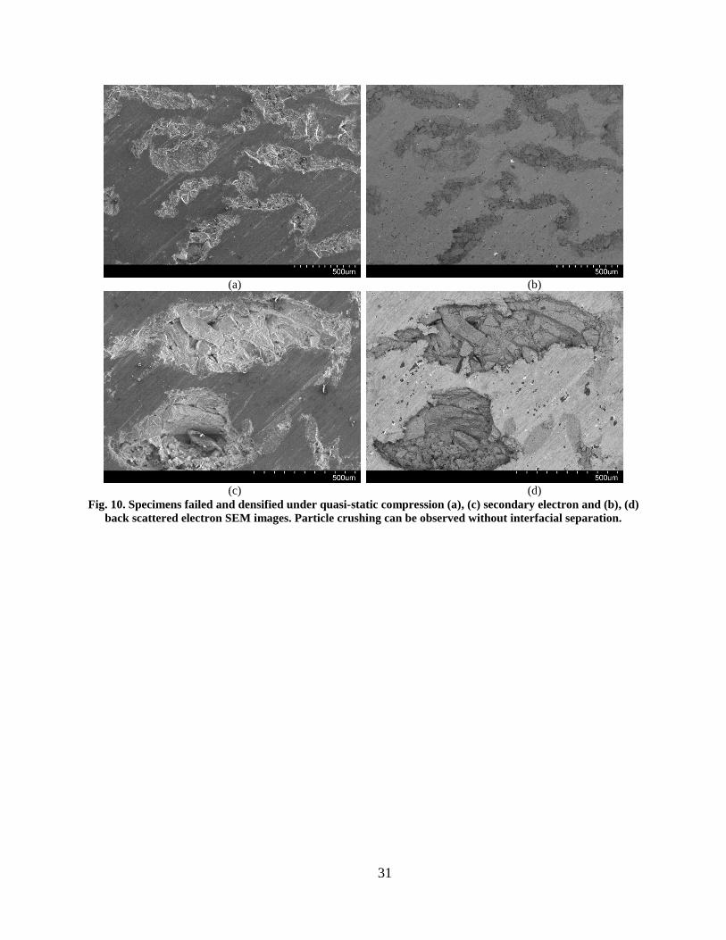
Specimens that failed under quasi-static loading condition are further analyzed using the SEM. The
micrographs are shown in Fig. 10. The specimens are sectioned in the loading direction using an Isomat diamond
blade saw and the micrographs are taken on the as-cut surface. SiCHS particles are completely crushed in the
specimens at complete densification, as observed in these micrographs. BSE image in Fig. 10b and d clearly show
the hollow sphere and the matrix phases. Complete densification of porosity is observed in these figures due to
extensive plastic deformation of the matrix around debris.
A356/SiCHS specimens subjected to HSR compression are also analyzed for failure features. A lower
magnification image of failed specimen is shown in Fig. 11a. A shear band can be observed in this image, marked
by a rectangle. SiCHS particles along this band have crushed and their cavities are consumed by the compressing

9
material as observed in Fig. 11b. Large scale matrix deformation in this region has resulted in compaction of debris,
without the presence of matrix cracks in the vicinity. It can also be seen in Fig. 11a that spheres that are directly not
on the shear band, Fig. 11c, have developed cracks and fractured under compression as per the mechanism
demonstrated in Fig. 9c. These hollow spheres did not show signs of shearing at this stage. The formation of the first
shear band will depend on the presence of weak spheres along a plane but eventually additional shear bands generate
and all the hollow spheres fracture and densify as the compression reaches densification strain.
4 DISCUSSION
The compressive strength of syntactic foams can be obtained by a recent model [26] and the results can be
validated with the experimental values. The compressive strength of A356/SiCHS syntactic foam ( com ) is
expressed in terms of contributions of the yield strength of A356 matrix alloy (0) and the compressive strength of
hollow spheres (HS):
HScom C 23
0 1 (4)
where C is a constant. In some previous studies on similar materials, the value of C is estimated to be 0.3 [26, 27].
Since the SiCHS comprise a thin shell made of SiC and their inner part is hollow, their effective strength is different
from that of the SiC material. The compressive strength of SiCHS is expressed as [26]:
231 voidSiCHS VC (5)
where (SiC) is the compressive strength of the hollow sphere material and Vvoid is the void volume fraction of the
SiCHS, specified by
SiC
HSSiC
voidV
(6)
The densities of SiC and SiCHS are SiC =3150 kg/m3 and
HS =1160 kg/m3, respectively. The estimates
of SiC can be found in the literature varying from 3.9 to 4.6 GPa. Considering these values of SiC, the estimates for
SiCHS strength range from a minimum of 261.5 to a maximum of 308.4 MPa,. Using equation 4, the lowest and
highest values of com are calculated as 171.7 and 199.8 MPa. The experimental value of com is 163 MPa (Table 1),
which is close to the calculated lower limit. The theoretical estimates are 5.1 and 18.4% higher than the
experimental strength.

10
Weight saving potential of syntactic foams is an attractive characteristic that enables their applications in
weight sensitive structures. In recent literature, syntactic foams comprising a number of matrix materials have been
studied, which include pure metals and alloys of magnesium, aluminum, titanium, and iron. The difference in
density of matrix metals ( 7.1Mg , 7.2Al , 5.4Ti g/cm3) is also reflected in the densities of syntactic
foams. Fig. 12a shows yield strength values of metal matrix syntactic foams extracted from various studies† [11, 16,
28-36]. From the references, where the data are represented in the form of figures, the data points are extracted to
the best possible accuracy. The yield strength of syntactic foam is normalized with the matrix yield strength in Fig.
12b. Most papers have not reported the yield strength values for the matrix alloys. Therefore, the base alloy
properties are taken from databases when necessary.
As a general trend, Fig. 12a shows that the yield strength of syntactic foams increases with density. Most of
the aluminum, titanium, and iron matrix syntactic foams confirm to this trend and fall inside a narrow ellipse. The
foams that defy this trend with better yield strength are mainly magnesium alloy and A356 aluminum alloy matrix
syntactic foams. The use of SiC hollow spheres has resulted in the development of aluminum alloy matrix syntactic
foams that match the density and yield strength of existing magnesium matrix syntactic foams in the literature,
which have used low volume fraction of fly ash cenospheres. The trends indicate that the use of engineered SiCHS in
magnesium alloys can result in syntactic foams with lower density and higher mechanical properties than most of
the existing syntactic foams.
The results of strain rate dependent compressive properties obtained in the present study are also analyzed
and compared with the limited number of previous studies on aluminum matrix syntactic foams [20, 23, 34, 37, 38].
High strain rate properties of cp-Al/cenosphere have previously been reported in [23]. Two compositions of
syntactic foams, containing cenospheres of 70 and 65 vol.% of 90 and 150 µm size, respectively, were studied. The
flow stress of foams containing 90 µm cenosphere was 21% higher than the matrix material. However, the foams
containing 150 µm cenospheres had 45% lower flow stress than the cp-Al. It is also noted that the compressive
strength values at high strain rate are higher than the quasi-static values. However, within the high strain rate range
(1400-5000 s-1
), the peak and plateau strengths did not show any variation. Similar trends were observed in another
study on A4032 matrix syntactic foams containing 5 wt.% fly ash cenospheres [34]. No measurable strain rate
† Attempt is made to obtain data from all widely cited studies. Missing any reference is inadvertent.

11
sensitivity was observed up to 2136 s-1
strain rate. The syntactic foam did not have strain rate sensitivity at high
strain rates but had higher strength compared to quasi-static values.
HSR compressive properties of cp-Al (commercially pure Al) and 7075 alloy filled with mullite-silica
microspheres have been reported in a previous work [20]. The cp-Al composites showed a peak strength of 109
MPa. The as-cast and T6 treated 7075 alloy composites showed a peak strength of 199 and 209 MPa, respectively.
At a strain rate of 2300 s-1
, the cp-Al, 7075, and 7075-T6 syntactic foams showed peak strengths of 140, 231, and
248 MPa, respectively. The results of this study corroborate with others that the peak strength values at high strain
rates were higher than those observed under quasi-static compression. However, the observation in other studies that
there was no measurable strain rate sensitivity within the high strain rate range cannot be confirmed for these foams
because this work presented results only at 2300 s-1
.
A series of papers have examined a composite foam containing fly ash cenospheres and closed-cell gas
porosity in A2014 alloy for strain rate sensitivity [37-39]. These composite foams show stress-strain curves similar
to syntactic foams, where a plateau region is observed and the densification strain is as high as 0.7. The compressive
testing is conducted in the strain rate range 10-2
-101 s
-1. Two of these papers present results from the same set of
experiments. The plateau stress increased with the foam density. However, no measurable effect of strain rate is
observed on the properties of the composite in the strain rate range explored in these papers.
In summary, the results from the published studies indicate that there is a difference in the quasi-static and
HSR compressive peak strength and plateau stress values. However, within the high strain rate range, these
properties did not show any difference. The applied theories for SHPB neglect several factors such as specimen
inertia, temperature rise (especially relevant at high compressive strains), and radial dispersion. These factors may
cause the HSR compressive strength to be different than the quasi-static values and explain why no difference is
observed as the strain rate is changed using SHPB technique.
Further comparison is drawn between the reported strength values with respect to compressive strain rate
for open and closed-cell aluminum foams containing gas porosity and syntactic foams in Fig. 13† [25, 37, 38, 40-
53]. It should be noted that the definition of strength may not be the same in all references. The peak strength
observed after the initial linear elastic region is termed as strength in most cases. However, sometimes yield strength
is termed as strength. Hence, there may be some differences in the values based on the definition used, which is not
† Attempt is made to obtain data from all widely cited studies. Missing any reference is inadvertent.
12
always clearly specified in the publications. The strength axis is represented on a log scale in Fig. 13. The strain rate
axis is plotted on normal and log scales in Fig. 13a and b, respectively, to clearly illustrate the trends obtained in the
data at high and quasi-static strain rates. In these figures, a dotted line separates the zones of syntactic foams and gas
porosity foams. The highest strength in gas porosity foams is observed as 31 MPa. It is important to note that most
aluminum matrix syntactic foams have a compressive strength over 100 MPa. These observations are limited to the
data reported in the literature but the numbers may be different for other compositions. The strength increases with
foam density for all types of foams. However, the density based trends are not included in this figure. Only some
foams show strain rate sensitivity as per the data compiled in this figure. A small positive or negative slope may not
conclusively mean strain rate sensitivity because standard deviation in the properties of foams can be considerably
large. It is observed in Fig. 13b that a large number of foams have strengths below 5 MPa. Use of such foams in
structural applications is difficult, unless they are present in the form of sandwich structures. These low strength
foams may be suitable for applications related to energy absorption under compression, vibration damping, and core
materials in sandwich structures.
The specimens used in the present work, and also in most published studies, are in the as-cast condition.
Heat treatments can improve the mechanical properties of these syntactic foams, as previously observed for 7075
alloys [54, 55]. The results of the present study show that the SiCHS can provide high yield strength to syntactic
foams and break the general trend observed between yield strength and density. Such benefits can be carried over to
other syntactic foams, possibly of magnesium alloys, to enhance the performance of those syntactic foams by using
high quality engineered hollow particles.
5 CONCLUSIONS
Aluminum alloy A356/SiC hollow sphere reinforced syntactic foams are studied under quasi-static and
dynamic compression. Mechanical properties and failure mechanisms are analyzed. Clear evidence of hollow sphere
failure at the peak stress is obtained. The failure initiates by the fracture of weak particles; some of the cracks can
propagate to the matrix as well. Shear band formation in the matrix and shearing of SiCHS lead to the major failure
activity. Debris of hollow spheres is compacted in their own cavity and densification is obtained. The compressive
strength and plateau strength are measured as 163 and 110 MPa for composites having 60 vol.% SiCHS. The
composites did not show strain rate sensitivity up to 1520 s-1
strain rate. Analysis of yield strength from previous
13
studies shows that most of the existing data fall along a narrow zone and shows a trend that the yield strength
increases with the composite density. In general, it is desired to have composites with high yield strength without
having to increase the density. A356/SiCHS syntactic foams show a clear advantage over other aluminum matrix
syntactic foams, especially those containing fly ash cenospheres.
The A356/SiCHS syntactic foams studied in the present work and most aluminum matrix syntactic foams
previously studied have not shown strain rate sensitivity in compressive properties (up to 5000 s-1
used in some
experiments). Differences are observed between quasi-static and HSR compressive yield strength values, which may
be related to the difference in the test techniques rather than the fundamental material behavior.
ACKNOWLEDGMENTS
Portions of the research reported in this paper were performed in connection with U.S. Army Research
Laboratory contract W911NF-10-2-0084 with DST and Cooperative Working Agreement W911NF-11-2-0096 with
NYU-Poly. The views and conclusions contained in this presentation are those of the authors and should not be
interpreted as presenting the official policies or position, either expressed or implied, of the ARL or the U.S.
Government unless so designated by other authorized documents. Citation of manufacturers' or trade names does not
constitute an official endorsement or approval of the use notwithstanding any copyright notation hereon.
REFERENCES
[1] M.F. Moreno, C.J.R.G. Oliver, Compression creep of PM aluminum matrix composites reinforced with SiC
short fibres, Materials Science and Engineering: A, 418 (2006) 172-181.
[2] H. Tamura, Y. Tanaka, F. Saito, K.-I. Kondo, Quantitative analysis of debris from SiC-fiber-reinforced
aluminum-alloy targets impacted by spherical projectiles, International Journal of Impact Engineering, 38 (2011)
686-696.
[3] C. Sun, M. Song, Z. Wang, Y. He, Effect of particle size on the microstructures and mechanical properties of
SiC-reinforced pure aluminum composites, Journal of Materials Engineering and Performance, 20 (2011) 1606-
1612.
[4] V. Rajput, D. Mondal, S. Das, N. Ramakrishnan, A. Jha, Effect of SiCp addition on age-hardening of aluminium
composite and closed cell aluminium composite foam, Journal of Materials Science, 42 (2007) 7408-7414.
14
[5] S. Lee, D. Suh, D. Kwon, Microstructure and fracture of SiC-particulate-reinforced cast A356 aluminum alloy
composites, Metallurgical and Materials Transactions A, 27 (1996) 3893-3901.
[6] J.A. Liu, S.R. Yu, Z.Q. Huang, G. Ma, Y. Liu, Microstructure and compressive property of in situ Mg2Si
reinforced Mg-microballoon composites, Journal of Alloys and Compounds, 537 (2012) 12-18.
[7] J. Banhart, Manufacture, characterisation and application of cellular metals and metal foams, Progress in
Materials Science, 46 (2001) 559-632.
[8] L.J. Gibson, M.F. Ashby, Cellular Solids: Structure and Properties, Cambridge University Press, New York,
1999.
[9] N. Gupta, V.C. Shunmugasamy, High strain rate compressive response of syntactic foams: Trends in mechanical
properties and failure mechanisms, Materials Science and Engineering: A, 528 (2011) 7596-7605.
[10] P. Rohatgi, N. Gupta, B. Schultz, D. Luong, The synthesis, compressive properties, and applications of metal
matrix syntactic foams, JOM: Journal of the Minerals, Metals and Materials Society, 63 (2011) 36-42.
[11] Sudarshan, M.K. Surappa, Synthesis of fly ash particle reinforced A356 Al composites and their
characterization, Materials Science and Engineering: A, 480 (2008) 117-124.
[12] Sudarshan, M.K. Surappa, Dry sliding wear of fly ash particle reinforced A356 Al composites, Wear, 265
(2008) 349-360.
[13] Y. Mu, G. Yao, Effect of fly ash particles on the compressive properties of closed-cell aluminum foams,
Journal of Materials Engineering and Performance, 19 (2010) 995-997.
[14] D.P. Mondal, S. Das, N. Ramakrishnan, K. Uday Bhasker, Cenosphere filled aluminum syntactic foam made
through stir-casting technique, Composites Part A: Applied Science and Manufacturing, 40 (2009) 279-288.
[15] Y.D. Liu, J.L. Yu, Z.J. Zheng, J.R. Li, A numerical study on the rate sensitivity of cellular metals, International
Journal of Solids and Structures, 46 (2009) 3988-3998.
[16] P.K. Rohatgi, J.K. Kim, N. Gupta, S. Alaraj, A. Daoud, Compressive characteristics of A356/fly ash
cenosphere composites synthesized by pressure infiltration technique, Composites Part A: Applied Science and
Manufacturing, 37 (2006) 430-437.
[17] G.T. Gray III, Classic Split-Hopkinson pressure bar testing, in: ASM Handbook vol. 8: Mechanical Testing
and Evaluation, Materials Park, OH, 2000.

15
[18] K.R. Ravi, R.M. Pillai, B.C. Pai, M. Chakraborty, A novel approach for extracting and characterizing interfacial
reaction products in Al-SiCp composites, Metallurgical and Materials Transactions A, 38 (2007) 1666-1670.
[19] D.J. Lloyd, H. Lagace, A. McLeod, P.L. Morris, Microstructural aspects of aluminium-silicon carbide
particulate composites produced by a casting method, Materials Science and Engineering: A, 107 (1989) 73-80.
[20] D.K. Balch, D.C. Dunand, Load partitioning in aluminum syntactic foams containing ceramic microspheres,
Acta Materialia, 54 (2006) 1501-1511.
[21] N. Gupta, E. Woldesenbet, P. Mensah, Compression properties of syntactic foams: effect of cenosphere radius
ratio and specimen aspect ratio, Composites Part A: Applied Science and Manufacturing, 35 (2004) 103-111.
[22] M.D. Goel, M. Peroni, G. Solomos, D.P. Mondal, V.A. Matsagar, A.K. Gupta, M. Larcher, S. Marburg,
Dynamic compression behavior of cenosphere aluminum alloy syntactic foam, Materials & Design, 42 (2012) 418-
423.
[23] Z.Y. Dou, L.T. Jiang, G.H. Wu, Q. Zhang, Z.Y. Xiu, G.Q. Chen, High strain rate compression of cenosphere-
pure aluminum syntactic foams, Scripta Materialia, 57 (2007) 945-948.
[24] Z. Wang, H. Ma, L. Zhao, G. Yang, Studies on the dynamic compressive properties of open-cell aluminum
alloy foams, Scripta Materialia, 54 (2006) 83-87.
[25] V.S. Deshpande, N.A. Fleck, High strain rate compressive behaviour of aluminium alloy foams, International
Journal of Impact Engineering, 24 (2000) 277-298.
[26] G.H. Wu, Z.Y. Dou, D.L. Sun, L.T. Jiang, B.S. Ding, B.F. He, Compression behaviors of cenosphere–pure
aluminum syntactic foams, Scripta Materialia, 56 (2007) 221-224.
[27] T. Mukai, H. Kanahashi, T. Miyoshi, M. Mabuchi, T.G. Nieh, K. Higashi, Experimental study of energy
absorption in a close-celled aluminum foam under dynamic loading, Scripta Materialia, 40 (1999) 921-927.
[28] A. Daoud, Effect of strain rate on compressive properties of novel Zn12Al based composite foams containing
hybrid pores, Materials Science and Engineering: A, 525 (2009) 7-17.
[29] A. Daoud, Effect of fly ash addition on the structure and compressive properties of 4032-fly ash particle
composite foams, Journal of Alloys and Compounds, 487 (2009) 618-625.
[30] A. Daoud, M.T. Abou El-khair, M. Abdel-Aziz, P. Rohatgi, Fabrication, microstructure and compressive
behavior of ZC63 Mg-microballoon foam composites, Composites Science and Technology, 67 (2007) 1842-1853.
16
[31] X.B. Xue, Y.Y. Zhao, V. Kearns, R.L. Williams, Mechanical and biological properties of titanium syntactic
foams, in: Proceedings of TMS 2010 Annual Meeting & Exhibition,, February 14-18, 2010, Seattle, WA, 2010, pp.
129-135.
[32] P.K. Rohatgi, A. Daoud, B.F. Schultz, T. Puri, Microstructure and mechanical behavior of die casting AZ91D-
Fly ash cenosphere composites, Composites Part A: Applied Science and Manufacturing, 40 (2009) 883-896.
[33] D. Luong, N. Gupta, P. Rohatgi, The high strain rate compressive response of Mg-Al alloy/fly Ash cenosphere
composites, JOM: Journal of the Minerals, Metals and Materials Society, 63 (2011) 48-52.
[34] D. Luong, N. Gupta, A. Daoud, P. Rohatgi, High strain rate compressive characterization of aluminum alloy/fly
ash cenosphere composites, JOM: Journal of the Minerals, Metals and Materials Society, 63 (2011) 53-56.
[35] L. Peroni, M. Scapin, M. Avalle, J. Weise, D. Lehmhus, Dynamic mechanical behavior of syntactic iron foams
with glass microspheres, Materials Science and Engineering: A, 552 (2012) 364–375.
[36] X. Xue, Y. Zhao, Ti matrix syntactic foam fabricated by powder metallurgy: particle breakage and elastic
modulus, Jom, 63 (2011) 43-47.
[37] D.P. Mondal, M.D. Goel, S. Das, Compressive deformation and energy absorption characteristics of closed cell
aluminum-fly ash particle composite foam, Materials Science and Engineering: A, 507 (2009) 102-109.
[38] D.P. Mondal, M.D. Goel, S. Das, Effect of strain rate and relative density on compressive deformation
behaviour of closed cell aluminum-fly ash composite foam, Materials & Design, 30 (2009) 1268-1274.
[39] D.P. Mondal, N. Jha, A. Badkul, S. Das, R. Khedle, High temperature compressive deformation behaviour of
aluminum syntactic foam, Materials Science and Engineering: A, 534 (2012) 521-529.
[40] M. Avalle, D. Lehmhus, L. Peroni, H. Pleteit, P. Schmiechen, G. Belingardi, M. Busse, AlSi7 metallic foams –
aspects of material modelling for crash analysis, International Journal of Crashworthiness, 14 (2009) 269-285.
[41] C.M. Cady, G.T. Gray III, C. Liu, M.L. Lovato, T. Mukai, Compressive properties of a closed-cell aluminum
foam as a function of strain rate and temperature, Materials Science and Engineering: A, 525 (2009) 1-6.
[42] R. Edwin Raj, V. Parameswaran, B.S.S. Daniel, Comparison of quasi-static and dynamic compression behavior
of closed-cell aluminum foam, Materials Science and Engineering: A, 526 (2009) 11-15.
[43] F. Han, H. Cheng, Q. Wang, Z. Li, The strain rate effect of an open cell aluminum foam, Metallurgical and
Materials Transactions A, 36 (2005) 645-650.

17
[44] H. Kanahashi, T. Mukai, Y. Yamada, K. Shimojima, M. Mabuchi, T. Aizawa, K. Higashi, Experimental study
for the improvement of crashworthiness in AZ91 magnesium foam controlling its microstructure, Materials Science
and Engineering: A, 308 (2001) 283-287.
[45] Y.-A. Kang, J.-Y. Zhang, J.-C. Tan, Compressive behavior of aluminum foams at low and high strain rates,
Journal of Central South University of Technology, 14 (2007) 301-305.
[46] B.V. Krishna, S. Bose, A. Bandyopadhyay, Strength of open-cell 6101 aluminum foams under free and
constrained compression, Materials Science and Engineering: A, 452-453 (2007) 178-188.
[47] S. Ramachandra, P. Sudheer Kumar, U. Ramamurty, Impact energy absorption in an Al foam at low velocities,
Scripta Materialia, 49 (2003) 741-745.
[48] D. Ruan, G. Lu, F.L. Chen, E. Siores, Compressive behaviour of aluminium foams at low and medium strain
rates, Composite Structures, 57 (2002) 331-336.
[49] J. Shen, G. Lu, D. Ruan, Compressive behaviour of closed-cell aluminium foams at high strain rates,
Composites Part B: Engineering, 41 (2010) 678-685.
[50] M. Tane, T. Kawashima, H. Yamada, K. Horikawa, H. Kobayashi, H. Nakajlma, Strain rate dependence of
anisotropic compression behavior In porous Iron with unidirectional pores, Journal of Materials Research, 25 (2010)
1179-1190.
[51] Z. Wang, J. Shen, G. Lu, L. Zhao, Compressive behavior of closed-cell aluminum alloy foams at medium strain
rates, Materials Science and Engineering: A, 528 (2011) 2326-2330.
[52] F. Yi, Z. Zhu, S. Hu, P. Yi, L. He, T. Ning, Dynamic compressive behavior of aluminum alloy foams, Journal
of Materials Science Letters, 20 (2001) 1667-1668.
[53] F. Yi, Z. Zhu, F. Zu, S. Hu, P. Yi, Strain rate effects on the compressive property and the energy-absorbing
capacity of aluminum alloy foams, Materials Characterization, 47 (2001) 417-422.
[54] D.K. Balch, J.G. O'Dwyer, G.R. Davis, C.M. Cady, G.T. Gray III, D.C. Dunand, Plasticity and damage in
aluminum syntactic foams deformed under dynamic and quasi-static conditions, Materials Science and Engineering
A, 391 (2005) 408-417.
[55] D. Lehmhus, J. Banhart, Properties of heat-treated aluminium foams, Materials Science and Engineering: A,
349 (2003) 98-110.

18
Figure Captions
Fig. 1. (a) Scanning electron micrograph of a sample of SiC hollow spheres and (b) wall thickness can be
visualized in a broken particle.
Fig. 2. Optical micrographs of A356/SiCHS composites showing (a,b) particle distribution in the composite.
The particles are wetted well with the alloy. Even the closely spaced particles have a layer of matrix between them;
(c,d) wetting of particle with the matrix alloy and mechanical interlocking at the particle-matrix interface.
Fig. 3. EDS analysis on (a) SiC hollow sphere and (b) matrix in the as-fabricated composite.
Fig. 4. Quasi-static compressive stress-strain graphs of A356/SiCHS syntactic foam.
Fig. 5. High strain rate test results from an A356/SiCHS syntactic foam tested at 970 s-1
strain rate (a) strain
pulses obtained from incident and transmitter bars, (b) validation of strain output, and (c) strain rate-strain and
stress-strain graphs.
Fig. 6. Scanning electron micrographs of an as-fabricated A356/SiCHS syntactic foam obtained using (a)
secondary electron and (b) back scattered detector.
Fig. 7. Cracks noticed in one of the hollow spheres.
Fig. 8. Locations on stress-strain diagram for observations presented in Fig. 9.
Fig. 9. Observations of various stages of material failure in A356/SiCHS syntactic foams (a)-(f) correspond
to successive stages of quasi-static compressive failure as represented in Fig. 8. Failure mechanisms marked with 1
and 2 are displayed in sketches included in c and e, respectively.
Fig. 10. Specimens failed and densified under quasi-static compression (a), (c) secondary electron and (b),
(d) back scattered electron SEM images. Particle crushing can be observed without interfacial separation.
Fig. 11. Scanning electron micrograph of A356/SiCHS syntactic foam tested at 1220 s-1
strain rate. (a) A
shear band with hollow sphere failure is observed, (b) close observation of a particle failed along shear band and (c)
failure of a particle away from the shear band; cracks in the loading direction initiate and cause failure of the
particle.
Fig. 12. Comparison of results obtained from the present study with literature data on aluminum,
magnesium, titanium, and iron matrix syntactic foams. The studies use different types of alloys and hollow particles
(only ceramic particle filled syntactic foams are added). The pressure listed for titanium matrix syntactic foams
refers to that used in composite synthesis.

19
Fig. 13. Comparison of strength values for open and closed-cell aluminum foams containing gas porosity
with those of aluminum matrix syntactic foams. The strain rate values are plotted on (a) normal axis and (b) log
axis. In both cases the strength values are plotted on log axis.

20
Table 1. Quasi-static compressive properties of A356/SiCHS syntactic foams.
Specimen
No.
Modulus
(GPa)
Compressive Strength
(MPa)
Plateau Stress
(MPa)
Densification Strain
(mm/mm)
1 2.08 161 107 0.46
2 1.85 152 111 0.48
3 1.71 161 102 0.42
4 2.02 162 105 0.48
5 2.10 181 126 0.45
Average 1.95 163 110 0.46
St. Dev. 0.17 11 9 0.03

21
Table 2. High strain rate properties of A356/SiCHS syntactic foams measured from SHPB testing.
Specimen
No.
Strain Rate
(/s)
Compressive Strength
(MPa)
Modulus
(GPa)
1 940 124.5 4.7
2 970 119.0 3.0
3 1160 125.5 5.2
4 1165 123.0 3.6
5 1220 120.7 5.7
6 1310 119.3 3.0
7 1425 130.1 3.5
8 1520 125.7 5.8

22
(a) (b)
Fig. 1. (a) Scanning electron micrograph of a sample of SiC hollow spheres and (b) wall thickness can be
visualized in a broken particle.

23
(a) (b)
(c) (d)
Fig. 2. Optical micrographs of A356/SiCHS composites showing (a,b) particle distribution in the composite.
The particles are wetted well with the alloy. Even the closely spaced particles have a layer of matrix between
them; (c,d) wetting of particle with the matrix alloy and mechanical interlocking at the particle-matrix
interface.

24
(a) (b)
Fig. 3. EDS analysis on (a) SiC hollow sphere and (b) matrix in the as-fabricated composite.
Energy (keV)1 2 3
Cou
nts
,
1000
1.3
2.5
3.8
6.3
5.0
Energy (keV)1 2 3
Cou
nts
,
1000
0.7
1.4
2.1
3.6
2.8

25
Fig. 4. Quasi-static compressive stress-strain graphs of A356/SiCHS syntactic foam.
0
50
100
150
200
250
300
-0.05 0.15 0.35 0.55
Str
ess
(M
Pa
)
Strain (mm/mm)

26
(a) (b)
(c)
Fig. 5. High strain rate test results from an A356/SiCHS syntactic foam tested at 970 s-1
strain rate (a) strain
pulses obtained from incident and transmitter bars, (b) validation of strain output, and (c) strain rate-strain
and stress-strain graphs.
-1.2
-0.8
-0.4
0
0.4
0.8
250 500 750 1000
Str
ain
(x
10
-3m
m/m
m)
Time (μs)
Incident pulse
Transmitted pulse
Reflected pulse
0
0.2
0.4
0.6
0.8
1
1.2
0 50 100 150 200 250
Str
ain
(x
10
-3m
m/m
m)
Time (μs)
IncidentReflected+Transmitted
0
300
600
900
1200
0
30
60
90
120
0 0.05 0.1 0.15
Str
ain
ra
te (
s-1
)
Str
es
s (
MP
a)
Strain (mm/mm)
Stress Strain rate

27
(a) (b)
Fig. 6. Scanning electron micrographs of an as-fabricated A356/SiCHS syntactic foam obtained using (a)
secondary electron and (b) back scattered detector.

28
Fig. 7. Cracks noticed in one of the hollow spheres.

29
Fig. 8. Locations on stress-strain diagram for observations presented in Fig. 9.
0
40
80
120
160
200
0 0.1 0.2 0.3 0.4 0.5
Str
ess
(M
Pa
)
Strain (mm/mm)
a
b
c
d
e
f

30
(a) (b)
(c)
(d)
(e)
(f)
Fig. 9. Observations of various stages of material failure in A356/SiCHS syntactic foams (a)-(f) correspond to
successive stages of quasi-static compressive failure as represented in Fig. 8. Failure mechanisms marked
with 1 and 2 are displayed in sketches included in c and e, respectively.
Compression
direction
1 1
2 1 2
31
(a) (b)
(c) (d)
Fig. 10. Specimens failed and densified under quasi-static compression (a), (c) secondary electron and (b), (d)
back scattered electron SEM images. Particle crushing can be observed without interfacial separation.

32
(a) (b)
(c)
Fig. 11. Scanning electron micrograph of A356/SiCHS syntactic foam tested at 1220 s-1
strain rate. (a) A shear
band with hollow sphere failure is observed, (b) close observation of a particle failed along shear band and (c)
failure of a particle away from the shear band; cracks in the loading direction initiate and cause failure of the
particle.

33
(a)
(b)
Fig. 12. Comparison of results obtained from the present study with literature data on aluminum,
magnesium, titanium, and iron matrix syntactic foams. The studies use different types of alloys and hollow
particles (only ceramic particle filled syntactic foams are added). The pressure listed for titanium matrix
syntactic foams refers to that used in composite synthesis.
0
50
100
150
200
250
300
0 1 2 3 4 5 6
σys
(MP
a)
Density (g/cc)
Daoud (2009) Zn12Al foam
Daoud (2007) ZC63
Daoud (2009) 4032 foam
Tao (2009) 6082
Sudarshan(2008) A356
Luong(2011) A4032
Rohatgi (2006) A356
Rohatgi (2009) AZ91D
Luong(2011) AZ91D
Xue (2010) Ti (45 MPa)
Xue (2010) Ti (70 MPa)
Xue (2010) Ti (100 MPa)
Xue (2010) Ti (150 MPa)
Xue (2010) Ti (200 MPa)
Peroni (2012) Fe 99.7%
Present work
0
0.2
0.4
0.6
0.8
1
1.2
1.4
0 1 2 3 4 5 6
σy
s/ σ
ym
Density (g/cc)
Daoud (2007) ZC63
Tao (2009) 6082
Sudarshan(2008) A356
Luong(2011) A4032
Rohatgi (2006) A356
Rohatgi (2009) AZ91D
Luong(2011) AZ91D
Xue (2010) Ti (45 MPa)
Xue (2010) Ti (70 MPa)
Xue (2010) Ti (100 MPa)
Xue (2010) Ti (150 MPa)
Xue (2010) Ti (200 MPa)
Peroni (2012) Fe 99.7%
Present work

34
(a)
(b)
Fig. 13. Comparison of strength values for open and closed-cell aluminum foams containing gas porosity with
those of aluminum matrix syntactic foams. The strain rate values are plotted on (a) normal axis and (b) log
axis. In both cases the strength values are plotted on log axis.
0.1
1
10
100
1000
0 1000 2000 3000 4000 5000 6000
σs
tre
ng
th(M
Pa
)
Strain Rate (s-1)
Deshpande (1999) Duocel Deshpande (1999) Alulight Mukai (1999) ALPORASDannemann (2000) ALPORAS Hall (2000) AlSi7 Kanahashi (2000) SG91 APaul (2000) ALPORAS Yi (2001) Al open-cell foam Miyochi(2002)ALPORASRuan (2002) CYMAT Balch (2005) cp-Al Balch (2005) A7075-OBalch (2005) A7075-T6 Han (2005) cp-Al Mukai(2005)ALPORASLee (2006) Duocel Wang (2006) Al foam Dou (2007) cp-AlKang (2007) Al Cady (2008) ALPORAS Edwin Raj (2009) AlShen (2010) ALPORAS Luong (2011) A4032 Wang (2011) Al foamsPresent work
Syntactic foams
Open and closed cell foams
0.1
1
10
100
1000
0.00001 0.001 0.1 10 1000 100000
σs
tre
ng
th(M
Pa
)
Strain Rate (s-1)
Deshpande (1999) Duocel Deshpande (1999) Alulight Mukai (1999) ALPORASDannemann (2000) ALPORAS Hall (2000) AlSi7 Kanahashi (2000) SG91 APaul (2000) ALPORAS Yi (2001) Al open-cell foam Ruan (2002) CYMATMiyochi(2002)ALPORAS Balch (2005) cp-Al Balch (2005) A7075-OBalch (2005) A7075-T6 Han (2005) cp-Al Mukai(2005)ALPORASLee (2006) Duocel Wang (2006) Al foam Dou (2007) cp-AlKang (2007) Al Cady (2008) ALPORAS Edwin Raj (2009) AlShen (2010) ALPORAS Luong (2011) A4032 Wang (2011) Al foamsPresent work
Syntactic foams
Open and closed cell foams


![Advanced Cast Aluminum Alloys - DTIC · Wrought 7055 aluminum alloy is the highest strength conventionally processed, commercially available, wrought aluminum alloy [2]. The yield](https://img.pdfslide.us/doc/110x75/5f33c89d21254a014f5911cb/advanced-cast-aluminum-alloys-dtic-wrought-7055-aluminum-alloy-is-the-highest.jpg)