Embed Size (px)
Citation preview
t· I ~
AD 425700
DEVELOPMENT OF EDDY CURRENT INSPECTION EQUIPMENT
by
ROBERT C. GRUBINSKAS
MATERIALS TESTING LABORATORY
TECHNICAL REPORT
U. S. ARMY MATERIALS RESEARCH AGENCY WATERTOWN, MASSACHUSETTS 02172 NOVEMBER 1963
-~~ .c:•··') W"•., 'i\,f ' .,. " t:,,,, '
The findings in this report are not to be construed as an official Department of the Army position
DDC AVAILABILITY NOTICE
Qualified requesters may obtain copies of this report from Commanding Office~ Defense Documentation Center, C~eron Station, Alexandri~ Virginia 22314
DISPOSITION INSTRUCTIONS
Destroy; do not return
AD 425700 Nondestructive testing
Electromagnetic properties
DEVELOPMENT OF EDDY CURRENT INSPECTION EQUIPMENT
Technical Report AMRA TR 63-24
by
Robert C. Grubinskas
November 1963
AMCMS Code 4230.1.6018.60.07 Development of Eddy Current Inspection Equipment
MATERIALS TESTING LABORATORY U.S. ARMY MATERIALS RESEARCH AGENCY
WATERTOWN, MASSACHUSETTS 02172
U.S. ARMY MATERIALS RESEARCH AGENCY
DEVELOPMENT OF EDDY CURRENT INSPECTION EQUIPMENT
ABSTRACT
An eddy current test system .l1as been developed utilizing commercially available instruments as integral components. Emphasis l1as been placed upon the development of a versatile system which is capable of solving numerous specific inspection problems. Coil design studies have resulted in the development of alterable coil forms and a versatile eddy current test probe. The test system, employing both encircling and probe coils, has been applied to various nonferromagnetic materials such as aluminum, brass, copper, magnesium, and titanium witn satisfactory results.
APPROVED:
FRANK R. LARSON Acting Chief Materials Testing Laboratory
ROBERT C. GRUBINSKAS Physicist (Gen)
Chairman-
ABSTRACT
INTRODUCTION
EDDY CURRENT TEST FUNDAMENTALS .
COIL DESIGN
Encircling Coils
Probe Coils . . .
EXPERIMENTAL RESULTS
SUMMARY
APPENDIX .
REFERENCES .
CONTENTS
.
.
. .
. .
Page
3
3
7
9
13
18
19
22
INTRODUCTION
Whereas many eddy current test instruments have been designed to solve particular problems, a decision was made at the U. S. Army Materials Research Agency to develop a versatile eddy current test system possessing a wide scope of application. Utilizing commercially available instruments as integral components, emphasis was placed on the development of a system which is sufficiently general in nature to make possible its application to the solution of numerous specific inspection problems amenable to eddy current test methods. During the initial phase of this continuing project, the application of the system developed has been confined to the testing of nonferromagnetic materials. The resulting effort is the subject of this report.
The applications of eddy current test methods in the field of nondestructive testing have been successfully achieved in the three following areas: 1 (1) the measurement of conductivity, or a combination of conductivity and permeability; (2) the measurement of thickness of thin metal sections;· and (3) the detection and evaluation of surface and near-surface discontinuities and inhomogeneities. Eddy current test methods are most effective for the inspection of surface and near-surface specimen conditions, and are compatible to high production rates and completely automatic inspection systems. They are commonly used as important supplements to ultrasonic, radiographic, and magnetic particle test methods for obtaining a complete assessment of material integrity.
Because a knowledge of the fundamentals concerning the origin and properties of eddy currents is a prerequisite for the comprehension of the manner in which these currents are utilized in the nondestructive testing of materials, a discussion of eddy current fundamentals follows.
EDDY CURRENT TEST FUNDAMENTALS
Eddy currents are electromagnetically induced currents produced within an electrical conductor by subjecting it to a changing magnetic field. The distribution of these currents in terms of amplitude and phase· within a conductor subjected to a periodically varying electromagnetic field can be defined by the following equations for the two most commonly encountered geometries in the field of nondestructive testing, namely, plane and cylindrical.
2 For the plane geometry case
[ zK/2 r J --- zKi'2
-=- -=- . 2 jc~.~t--2-) lv = 1
0 e e •
-3-
. . . ( 1)
And for the cylindrical geometry case 3
. . . (2)
where
iv is the current density
i 0 is the value of the current density at the surface of the conductor
z is the depth
K is /w~cr
Bza0 is the value of the magnetic induction at the surface of the inductor
~ is the magnetic permeability
a is the conductivity
Mo(Ka), M1 (Kr) 80 (Ka) and. 81 (Kr) are conventional forms of Bessel functions
a is the radius of the cylinder
r is a radius which takes on any value between o and a.
The above equations were derived for ideal cases and are valid only if the conductor is homogeneous and of suitable dimensions to satisfy the conditions imposed by the respective derivations.
As the frequency is increased, the eddy currents tend to concentrate near the surface of the conductor, and at sufficiently high frequencies, there results the well-known skin effect. Because eddy current flow is confined to a region bounded by the surface of the specimen and the skin depth associated with the selected test frequency, test indications are obtained only by the direct interaction of eddy currents with the electromagnetic properties of this region which may or may not contain inhomogeneities or discontinuities, or both. These test indications may be optimized in some instances by a proper selection of frequency.
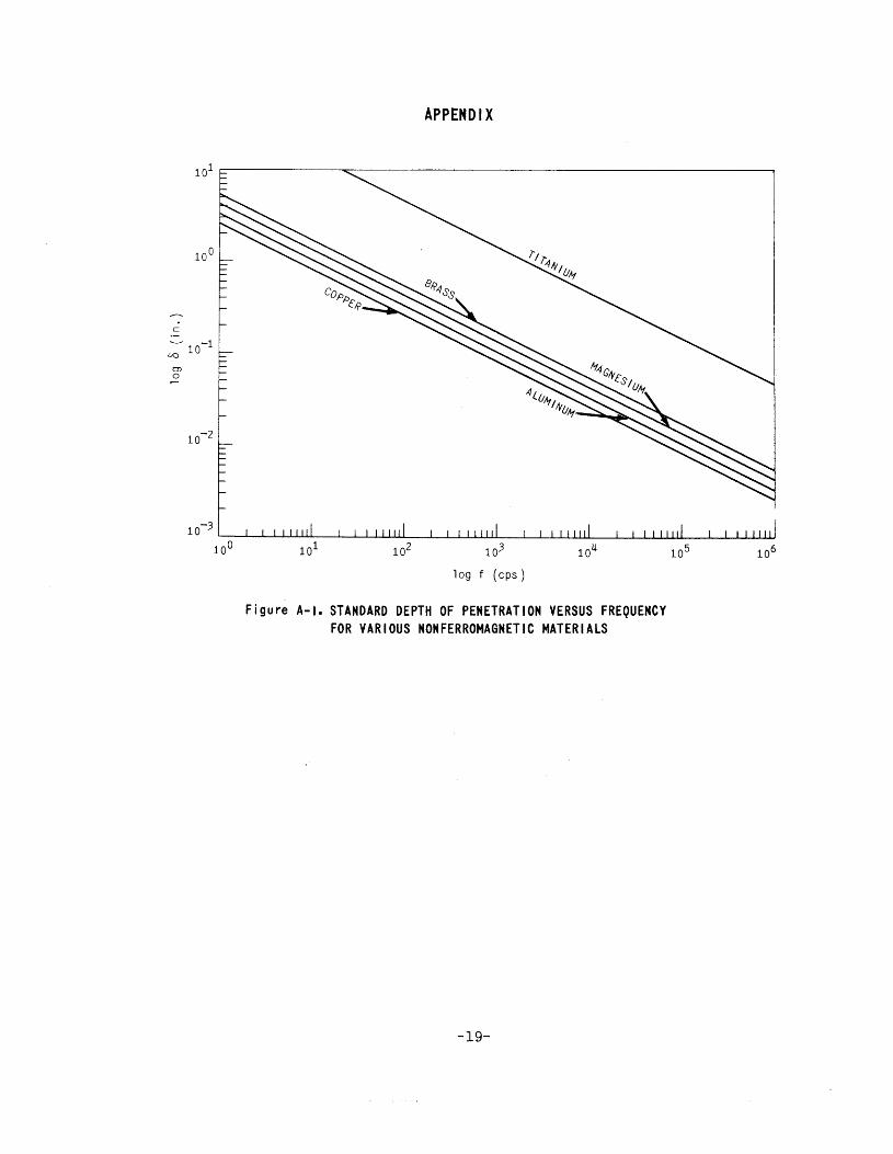
In order to facilitate the selection of a suitable test frequency for the inspection of nonferromagnetic materials, it is desirable to introduce the concepts of "depth of penetration" for both plane and cylindrical geometries and "critical frequency" for cylindrical geometries. The standard. depth of penetration, 6, is defined as that depth at which the eddy current density is 36.8 percent of the surface value. This definition for the plane geometry case is the result of equating the exponent of e of the second coefficient of Equation 1 to one and solving for z, which in turn is referred to as 6 so that4
6 1 . . . ( 3)
-4-
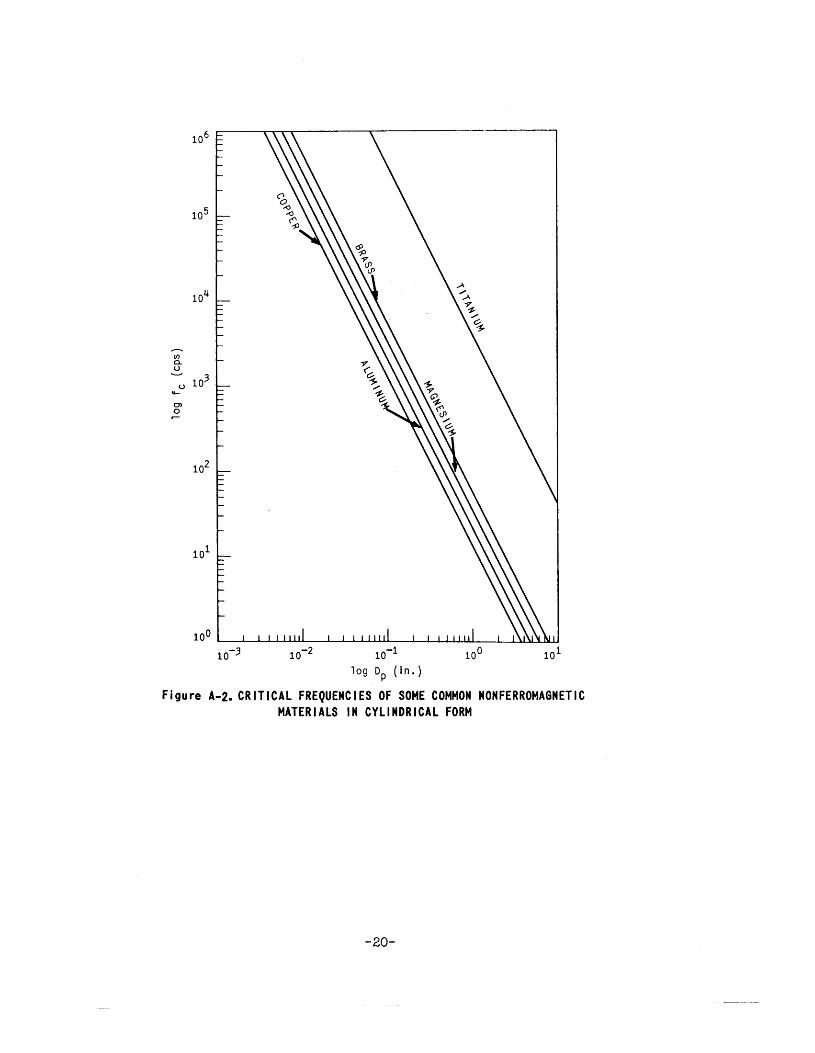
Likewise, in the cylindrical case, when the argument (Ka) of the Bessel functions appearing in Equation 2 is equated to one a.nd solved for f with the cylinder radius a being replaced by the cylinder diameter Dp,the resulting expression for this frequency which is referred to as the critical frequency fc is
fc 5 .08xl05
crD :-:.. p
. . . ( 4)
where the quantities in Equations 3 and 4 are in the following units:
6 in meters
CJ in mhos per meter
ll in henries per meter (l.l 47Txl0 - 7 h/m for nonferromagnetic materials)
fc in cycles per second
Dp in meters.
The parameter fc is incorporated in the "similarity principle of eddy current testing" which states that the eddy current and magnetic field strength distribution as well as the effective permeability within any test specimen are the same if the same multiple of the critical frequency is employed. Both of these concepts are due to Forster and are extensively used in the field of nondestructive testing. 5
Standard depth of penetration versus frequency and critical frequency versus specimen diameter curves, Figures A-1 and A-2 for such common nonferromagnetic materials as aluminum, brass, copper, magnesium, and titanium have been calculated using Equations 3 and 4. These curves are included in the appendix for use as guides in the selection of suitable test frequencies.
Nondestructive test methods utilizing induction currents generally consist of observing the changes in the electrical characteristics of an electromagnetic transducer produced by the induced currents of an electrical conductor which has been introduced into the electromagnetic field of the transducer. The transducer may consist of a single excitation coil or a system of coils, which in this report shall be referred to as a coil configuration.
Associated with the generation of eddy currents is a power loss within a conductor of finite resistivity which must be supplied by the inducing agent, and also, an electromagnetic field which is in opposition with the original inducing field. Consequently, changes are produced in both the resistive and reactive components of the impedance of the transducer in accordance with the magnitude, distribution, and phase of the induced eddy current. 1
-5-
The magnitude of the induced eddy currents will depend upon the relative position of the coil and the specimen; the magnitude and frequency of the inducing current; the presence of discontinuities or inhomogeneities in the specimen; the geometry of the specimen; and, finally, the electrical conductivity and magnetic permeability of the specimen and those factors which influence the magnitudes of these important physical constants. 4
Eddy current test coils may generally be included in any one of the following three classifications: encircling or feed-through, probe, and bobbin. Each of these classifications is subclassified into absolute and differential divisions. 1 The term absolute, as it is used here, refers to a coil or coils which respond to all the electromagnetic properties of the part, and the term differential refers to a configuration of two or more coils connected in phase opposition such that any electromagnetic condition of the specimen which is not common to the adjacent areas being subjected to inspection will produce an unbalance of the system and thereby be detected .6
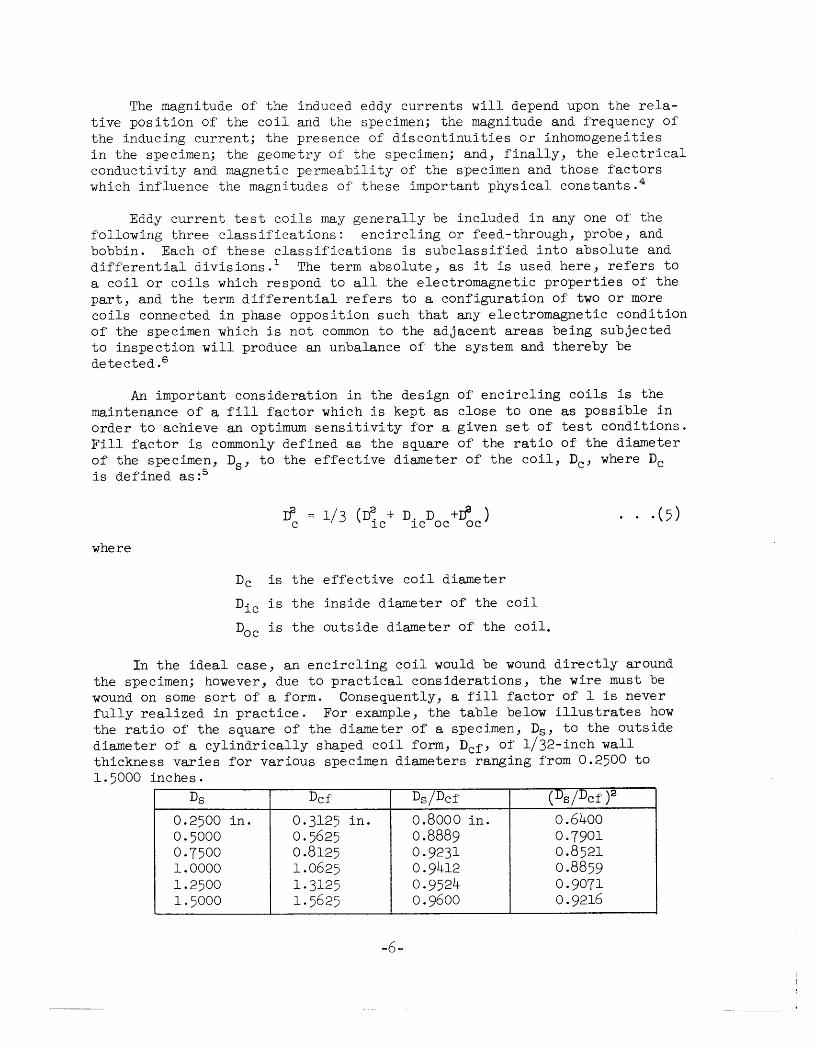
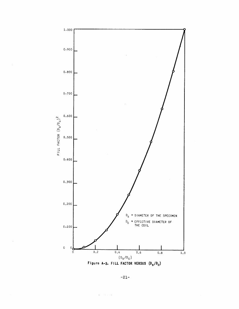
An important consideration in the design of encircling coils is the maintenance of a fill factor which is kept as close to one as possible in order to achieve an optimum sensitivity for a given set of test conditions. Fill factor is commonly defined as the square of the ratio of the diameter of the specimen, Ds, to the effective diameter of the coil, De, where De is defined as :5
rf 1/3 (D~ + D. D +rf ) . ( 5) c lC lC OC oc
where
De is the effective coil diameter
Die is the inside diameter of the coil
Doc is the outside diameter of the coil.
In the ideal case, an encircling coil would be wound directly around the specimen; however, due to practical considerations, the wire must be wound on some sort of a form. Consequently, a fill factor of 1 is never fully realized in practice. For example, the table below illustrates how the ratio of the square of the diameter of a specimen, Ds, to the outside diameter of a cylindrically shaped coil form, Dcf' of 1/32-inch wall thickness varies for various specimen diameters ranging from 0.2500 to 1.5000 inches.
Ds Dcf Ds/Dcf (DsjDcf )2
0.2500 in. 0.3125 in. 0.8000 in. 0.6400 0.5000 0.5625 0.8889 0.7901 0.7500 0.8125 0.9231 0.8521 1.0000 1.0625 0.9412 0.8859 1.2500 1.3125 0.9524 0.9071 1.5000 1. 5625 0.9600 0.9216
-6-
By referring to the table, it is seen that the mere use of an unwound coil form sleeve would reduce the maximwn obtainable fill factor to approximately 0.64 for 1/4-inch-diameter specimens and to approximately 0.92 for 1-1/2-inch-diameter specimens. A curve relating fill factor to the ratio Ds/Dc, FigureA-3, has been included in the appendix for practical reference.
It should be mentioned that a term similar to fill factor is sometimes encountered in the literature. This term has been defined as either the ratio of the diameter of the specimen to the diameter of the coil1 or as the ratio of the outside diameter of the specimen to the inside diameter of the coil and referred to as the "coil fill". 7
It should also be pointed out that for any coil having a finite wire build-up there are at least four diameters associated with the coil, namely: the inside diameter of the coil which is the same as the outside diameter of the coil form sleeve; the outside diameter; the average diameter; and an effective diameter. Consequently, quantities defined in terms of coil diameter should be specifically defined. Also, when the expression "inside diameter of the coil" is used, no account is taken of the wire build-up which, hypothetically, could be increased without limit.
Basically, any eddy current test system may be thought of as being comprised of three basic components, namely: (1) a source of coil excitation; (2) a coil configuration network; and (3) instrumentation for analyzing the eddy current test signal. Since commercially available instruments were going to be used as integral components of the system, it was decided to achieve an improvement in versatility in the coil configuration network which, in the final analysis, comprises the heart of any eddy current test system. Because encircling and probe coils are the ones most commonly encountered in the field of nondestructive testing, the coil design studies were restricted to the development of these two types.
COIL DESIGN
Enc i rc 1 i ng Co i 1 s
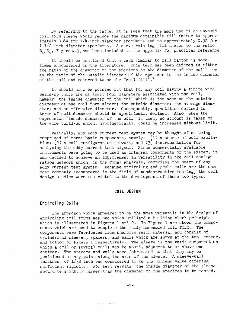
The approach which appeared to be the most versatile in the design of encj_rcling coil forms was one which utilized a building block principle which is illustrated in Figures 1 and 2. In Figure 1 are shown the components which are used to complete the fully assembled coil form. The components were fabricated from phenolic resin material and consist of cylindrical sleeves, spacers, and walls which are shown at the top, center, and bottom of Figure 1 respectively. The sleeve is the basic component on which a coil or several coils may be wound, adjacent to or above one another. The spacers and walls were fabricated so that they may be positioned at any point along the axis of the sleeve. A sleeve-wall thickness of 1/32 inch was considered to be the minimwn value offering sufficient rigidity. For best results, the inside diameter of the sleeve should be slightly larger than the diameter of the specimen to be tested.
-7-
• • 00
19-066-1857/0RD-62 Figure I. COMPONENTS OF PROTOTYPE ENCIRCLING COIL FORMS
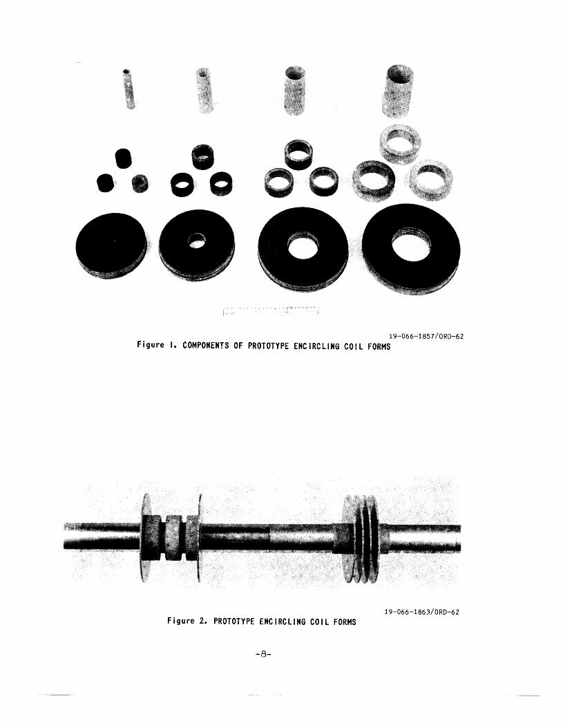
19-066-1863/0RD-62 Figure 2. PROTOTYPE ENCIRCLING COIL FORMS
-8-
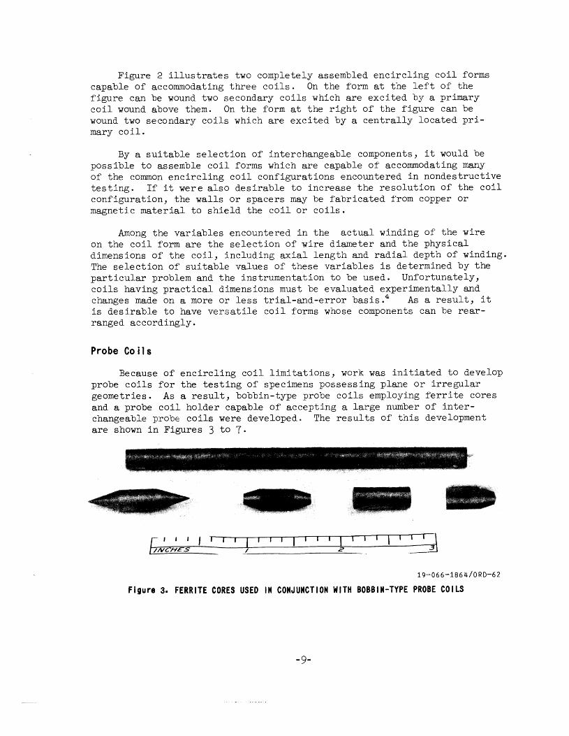
Figure 2 illustrates two completely assembled encircling coil forms capable of accommodating three coils. On the form at the left of the figure can be wound two secondary coils which are excited by a primary coil wound above them. On the form at the right of the figure can be wound two secondary coils which are excited by a centrally located primary coil.
By a suitable selection of interchangeable components, it would be possible to assemble coil forms which are capable of accommodating many of the common encircling coil configurations encountered in nondestructive testing. If it were also desirable to increase the resolution of the coil configuration, the walls or spacers may be fabricated from copper or magnetic material to shield the coil or coils.
Among the variables encountered in the actual winding of the wire on the coil form are the selection of wire diameter and the physical dimensions of the coil, including axial length and radial depth of winding. The selection of suitable values of these variables is determined by the particular problem and the instrumentation to be used. Unfortunately, coils having practical dimensions must be evaluated experimentally and changes made on a more or less trial-and-error basis.4 As a result, it is desirable to have versatile coil forms whose components can be rearranged accordingly.
Probe Co i 1 s
Because of encircling coil limitations, work was initiated to develop probe coils for the testing of specimens possessing plane or irregular geometries. As a result, bobbin-type probe coils employing ferrite cores and a probe coil holder capable of accepting a large number of interchangeable probe coils were developed. The results of this development are shown in Figures 3 to 7·
19-066-1864/0RD-62
Figure 3. FERRITE CORES USED IN CONJUNCTION WITH BOBBIN-TYPE PROBE COILS
-9-
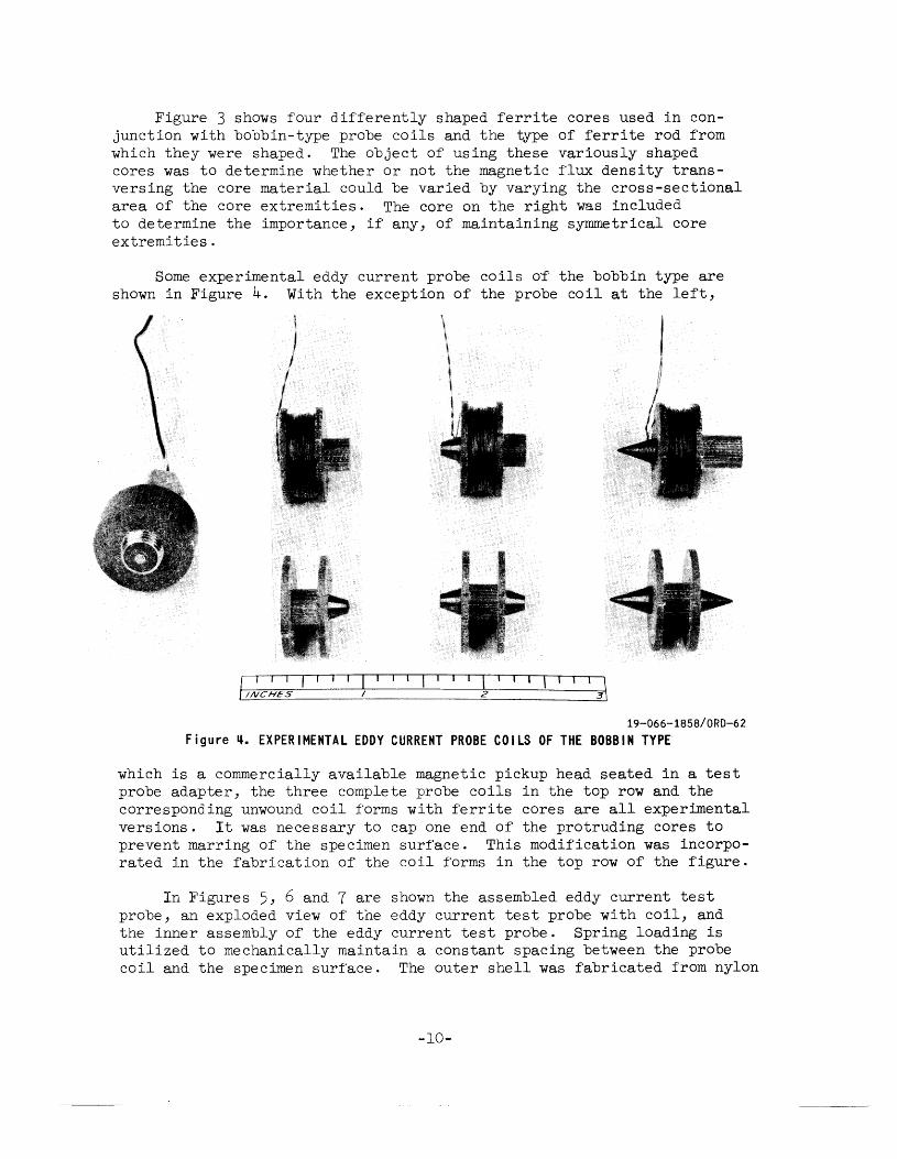
Figure 3 shows four differently shaped ferrite cores used in conjunction with bobbin-type probe coils and the type of ferrite rod from which they were shaped. The object of using these variously shaped cores was to determine whether or not the magnetic flux density transversing the core material could be varied by varying the cross-sectional area of the core extremities. The core on the right was included to determine the importance, if any, of maintaining symmetrical core extremities .
Some experimental eddy current probe coils or the bobbin type are shown in Figure 4. With the exception of the probe coil at the left,
j I I I I \ r!NCHES 2
19-066-1858/0RD-62
Figure ~. EXPERIMENTAL EDDY CURRENT PROBE COILS OF THE BOBBIN TYPE
which is a commercially available magnetic pickup head seated in a test probe adapter, the three complete probe coils in the top row and the corresponding unwound coil forms with ferrite cores are all experimental versions. It was necessary to cap one end of the protruding cores to prevent marring of the specimen surface. This modification was incorporated in the fabrication of the coil forms in the top row of the figure.
In Figures 5, 6 and 7 are shown the assembled eddy current test probe, an exploded view of the eddy current test probe with coil, and the inner assembly of the eddy current test probe. Spring loading is utilized to mechanically maintain a constant spacing between the probe coil and the specimen surface. The outer shell was fabricated from nylon
-10-
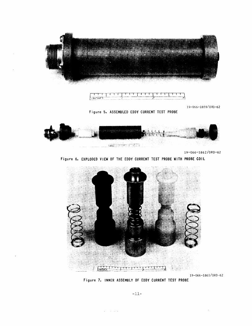
19-066-1859/QRD-62
Figure 5. ASSEMBLED EDDY CURRENT TEST PROBE
19-066-1862/0RD-62
Figure 6. EXPLODED VIEW OF THE EDDY CURRENT TEST PROBE WITH PROBE COIL
19-066-1861/0RD-62
Figure 7. INNER ASSEMBLY OF EDDY CURRENT TEST PROBE
-11-
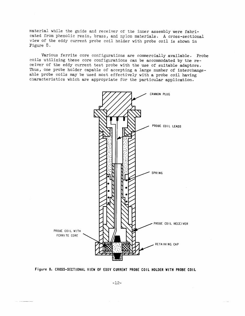
material while the guide and receiver of the inner assembly were fabricated from phenolic resin, brass, and nylon materials. A cross-sectional view of the eddy current probe coil holder with probe coil is shown in Figure 8.
Various ferrite core configurations are commercially available. Probe coils utilizing these core configurations can be accommodated by the receiver of the eddy current test probe with the use of suitable adaptors. Thus, one probe holder capable of accepting a large number of interchangeable probe coils may be used most effectively with a probe coil having characteristics which are appropriate for the particular application.
PROBE COIL WITH FERRITE CORE
CANNON PLUG
PROBE COIL LEADS
PROBE COIL RECEIVER
RETAINING CAP
Figure 8. CROSS-SECTIONAL VIEW OF EDDY CURRENT PROBE COIL HOLDER WITH PROBE COIL
-12-
EXPERIMENTAL RESULTS
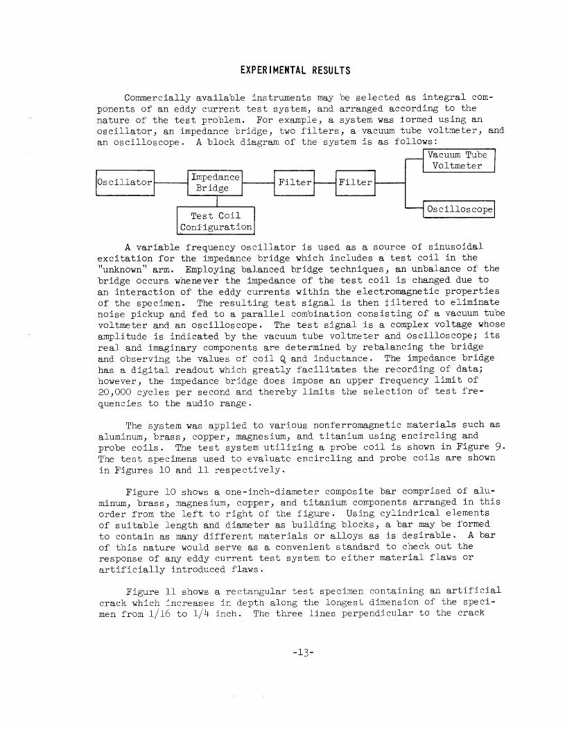
Commercially available instruments may be selected as integral components of an eddy current test system, and arranged according to the nature of the test problem. For example, a system was formed using an oscillator, an impedance bridge, two filters, a vacuum tube voltmeter, and an oscilloscope. A block diagram of the system is as follows:
.---------, Vacuum Tube Voltmeter
Oscilloscope
.Configuration
A variable frequency oscillator is used as a source of sinusoidal excitation for the impedance bridge which includes a test coil in the "unknown" arm. Employing balanced bridge techniques, an unbalance of the bridge occurs whenever the impedance of the test coil is changed due to an interaction of the eddy currents within the electromagnetic properties of the specimen. The resulting test signal is then filtered to eliminate noise pickup and fed to a parallel combination consisting of a vacuum tube voltmeter and an oscilloscope. The test signal is a complex voltage whose amplitude is indicated by the vacuum tube voltmeter and oscilloscope; its real and imaginary components are determined by rebalancing the bridge and observing the values of coil Q and inductance. The impedance bridge has a digital readout which greatly facilitates the recording of data; however, the impedance bridge does impose an upper frequency limit of 20,000 cycles per second and thereby limits the selection of test frequencies to the audio range.
The system was applied to various nonferromagnetic materials such as aluminum, brass, copper, magnesium, and titanium using encircling and probe coils. The test system utilizing a probe coil is shown in Figure 9· The test specimens used to evaluate encircling and probe coils are shown in Figures 10 and 11 respectively.
Figure 10 shows a one-inch-diameter composite bar comprised of aluminum, brass, magnesium, copper, and titanium components arranged in this order from the left to right of the figure. Using cylindrical elements of suitable length and diameter as building blocks, a bar may be formed to contain as many different materials or alloys as is desirable. A bar of this nature would serve as a convenient standard to check out the response of any eddy current test system to either material flaws or artificially introduced flaws.
Figure 11 shows a rectangular test specimen containing an artificial crack which increases in depth along the longest dimension of the specimen from l/16 to l/4 inch. The three lines perpendicular to the crack
-13-
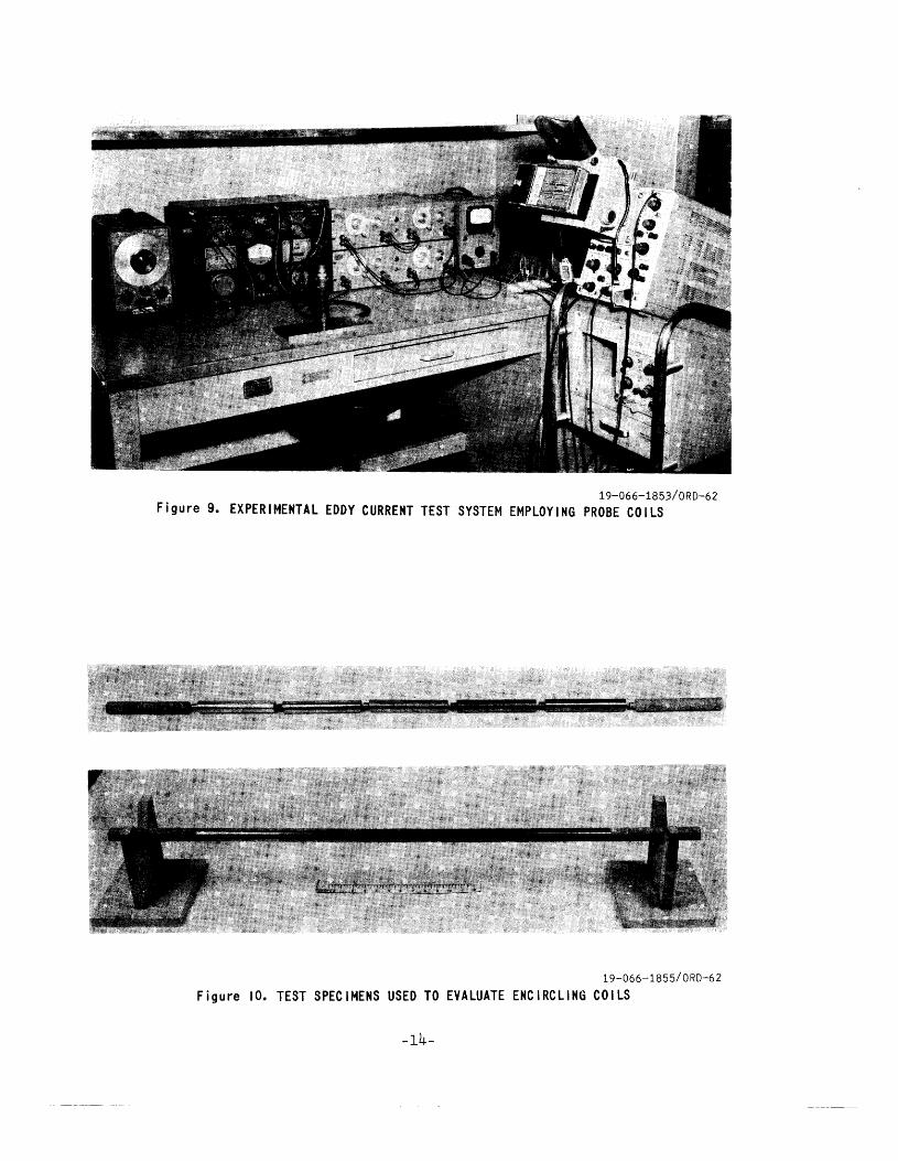
19-066-1853/0RD-62 Figure 9. EXPERIMENTAL EDDY CURRENT TEST SYSTEM EMPLOYING PROBE COILS
19-066-1855/0RD-62
Figure 10. TEST SPECIMENS USED TO EVALUATE ENCIRCLING COILS
-14-
19-066-1856/0RD-62 Figure I I. TEST SPECIMEN USED TO EVALUATE PROBE COILS
are pencil lines which were used as guides for passing various probe coils over the same portion of the crack. The specimen dimensions were 10 x 4 x l/2 inches. Rectangular specimens of aluminum, brass, copper, and magnesium were used to perform an initial evaluation of bobbin-type probe coils.
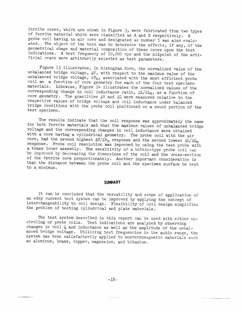
Figure 12 illustrates an impedance plane curve which was obtained by passing an encircling coil over the components of a one-inch-diameter composite test bar. The ordinate of any given point on the curve is the ratio of the inductive reactance of the coil having a metallic core to the inductive reactance of the coil having an air core, wL0 , while its abscissa is the ratio of the incremental resistance, 6R, to wL0 . The test parameters are indicated on the figure. Such a curve illustrates the effect of varying the conductivity of the core material upon the test coil impedance.
0.9
0.8
0.5
0.4
0 0.1
) Direction of
Increasing Conductivity
PARAMETERS: Test Frequency- 1.000 cps TEST COIL: 350 Turns of 28 AWG Wire R0c=s.5zsD Fill Factor = 0.62 Specimen Diameter- 1.000"
0.2 t\R
WL0
0.3 0.4 0-5
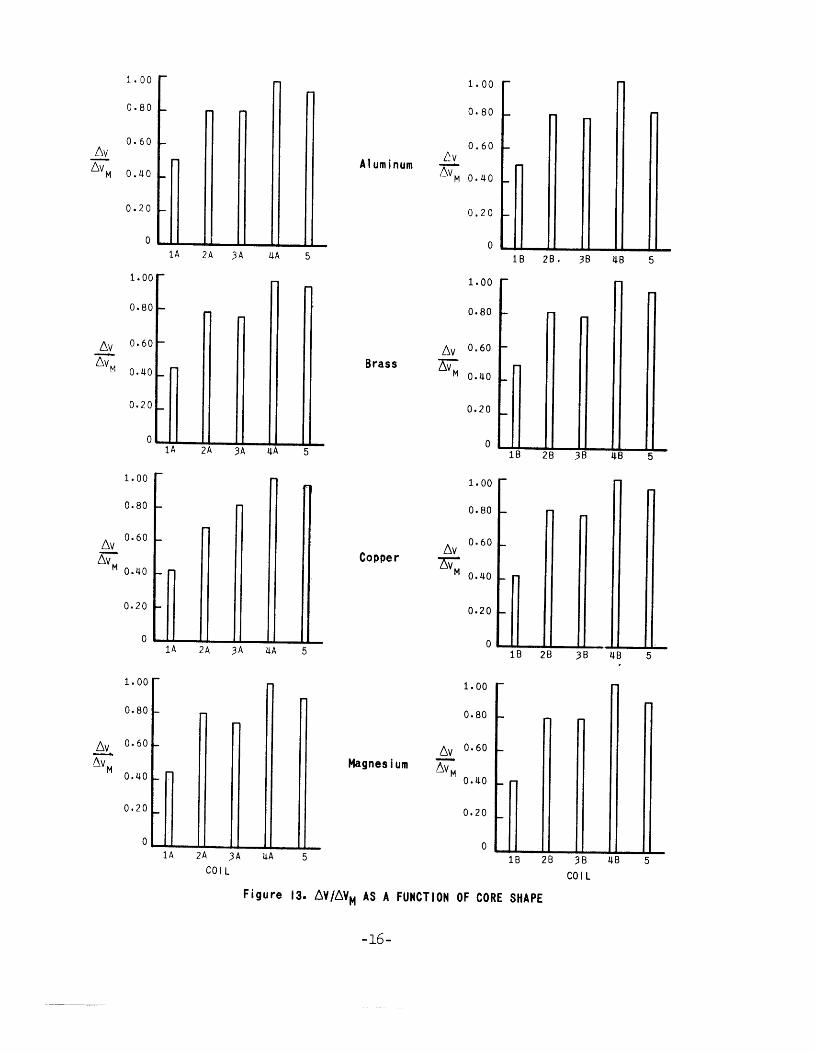
Figures 13 and 14 represent the results of passing identically wound probe coils having ferrite cores of axial cross-sections designated as types 1, 2, 3, and 4 over the midpoint of the longitudinal crack in each of the rectangular test specimens. These
1.~ 2.~ 3-~ 4.~
Figure 12. I MPEOANCE PLANE FOR COIL ENCIRCLING VARIOUS COMPONENTS OF
THE COMPOSITE TEST BAR
-15-
1. 00 ,....
o.so -0.60 f-
6v 6vM 0.40 f-
0.20 r-
0
1.00 r-
o.so t-
6v 0.60 -6vM
0.40 r-
o. 20 r-
0
1.00 r-
o.so I-
6v 0.60 r-
EV M 0.40 -
0.20 f-
0
1.00 r-
o.so t-
6v 0.60 1-
~ 0.40 1-
0.20 ~
0
...
r
r
1A 2A 3A 4A 5
r
1A 2A 3A 4A 5
r-
I"'
1A 2A 3A 4A 5
1A
I"'
2A 3A COIL
4A 5
Aluminum t.v zw:
6v Brass ~
6v Copper ~
6v Magnesium ~
1. 00 r-
o.so 1-
0.60 1-
0.40 1-
0. 2 0 1-
0 18 28.
1. 00 r-
o.ao 1- ...
0.60 r-
0.40 1-
0.20 1-
0 18 28
1.00 .-
o.so -
0.60 -
0.40 ~
0.20 1-
0 18 28
1. 00 r-
o.so 1- ...
0.60 1-
0.40 1-
0.20 -0
18 28
Figure 13. ~V/~VM AS A FUNCTION OF CORE SHAPE
-16-
38 48 5
...
38 48 5
38 48 5
r
38 48 5 COIL
1. 00 r-
o.ao r-
0.20 r-
1. 00 """
0.80 r-
r-
f-
0.20 1-
0 n 1A
1.00 -
0.80 .....
.6L 0.60 f-
fu Mo.~Or-
0.20 ~
0 n 1A
1. 00
0.80
0.60 .6L
.6L M o.~o
!A
1.00,..
0.80 ~
Aluminum
1. 00 r-
0.80 ~
Brass
0.20 -
2A 3A ~A 5
1.00 r-
o. 80 r-
Copper
0.20 ~
2A 3A ~A 5
1. 00 r-
0.80 -
Magnesium
0 n 2A 3A ~A 5 18 COIL
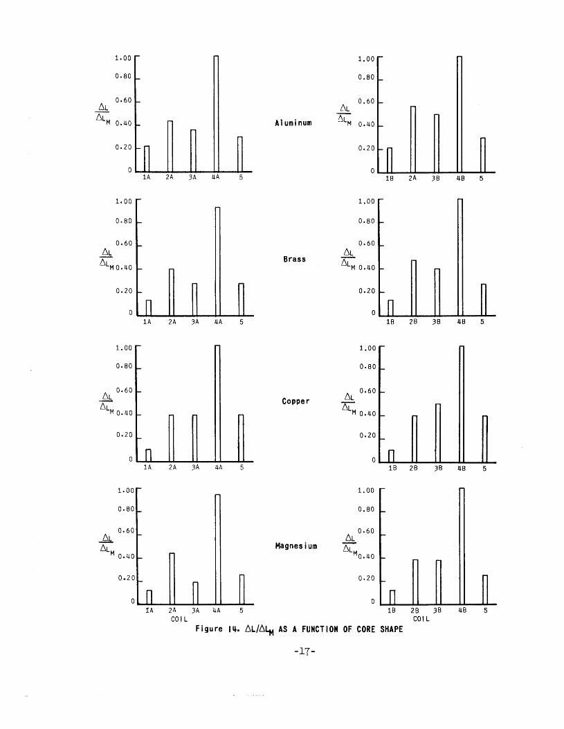
Figure jij. 6L/6LM AS A FUNCTION OF CORE SHAPE
-17-
r
28 38 COIL
I""
~8 5
48 5
~8 5
ferrite cores, which are shown in Figure 3, were fabricated from two types of ferrite material which were classified as A and B respectively. A probe coil having an air core and designated as number 5 was also evaluated. The object of the test was to determine the effects, if any, of the geometrical shape and material composition of these cores upon the test indications. A test frequency of 10,000 cps and the midpoint of the artificial crack were arbitrarily selected as test parameters.
Figure 13 illustrates, in histogram form, the normalized value of the unbalanced bridge voltage, ~V, with respect to the maximum value of the unbalanced bridge voltage, 6Vm, associated with the most efficient probe coil as a function of core geometry for each of the four test specimen materials. Likewise, Figure 14 illustrates the normalized values of the corresponding change in coil inductance ratio, 6L/6Lm, as a function of core geometry. The quantities ~V and 61 were measured relative to the respective values of bridge voltage and coil inductance under balanced bridge conditions with the probe coil positioned on a sound portion of the test specimen.
The results indicate that the coil response was approximately the same for both ferrite materials and that the maximum values of unbalanced bridge voltage and the corresponding changes in coil inductance were obtained with a core having a cylindrical geometry. The probe coil with the air core, had the second highest 6V/~Vm response and the second lowest 6L/6Lm response. Probe coil resolution was improved by using the test probe with a brass inner assembly. The sensitivity of a bobbin-type probe coil can be improved by decreasing the dimensions of the coil and the cross-section of the ferrite core proportionately. Another important consideration is that the distance between the probe coil and the specimen surface be kept to a minimum.
SUMMARY
It can be concluded that the versatility and scope of application of an eddy current test system can be improved by applying the concept of interchangeability to coil design. Flexibility of coil design simplifies the problem of testing cylindrical and plate materials.
The test system described in this report can be used with either encircling or probe coils. Test indications are analyzed by observing changes in coil Q and inductance as well as the amplitude of the unbalanced bridge voltage. Utilizing test frequencies in the audio range, the system has been satisfactorily applied to nonferromagnetic materials such as aluminum, brass, copper, magnesium, and titanium.
-18-
APPENDIX
101 c-------------~------------------------------------------~
c ·-~ -1 uo 10
01 0
103
log f (cps)
Figure A-J. STANDARD DEPTH OF PENETRATION VERSUS FREQUENCY FOR VARIOUS NONFERROMAGNETIC MATERIALS
-19-
en a. 0
0 103 .._ o> 0
100 ~~-L~~u_~~~~~--~~~~--~~~~ 10-.3 10-1
log Dp (In.)
Figure A-2. CRITICAL FREQUENCIES OF SOME COMMON NONFERROMAGNETIC MATERIALS IN CYLINDRICAL FORM
-20-
N ....--..
u Cl .........
(/)
Cl
ct: 0 1-u <( lL.
_J _J
lL.
1.000
0.900
o.aoo
0.700
0.600
0.500
0.400
0.300
0.200
0~100
0
08 =DIAMETER OF THE SPECIMEN
De =EFFECTIVE DIAMETER OF THE COIL
0.2 0.4 0.6 0.8
(Ds/Dc)
Figure A-3. FILL FACTOR VERSUS (08 /Dc)
-21-
1.0
REFERENCES
1. ALLEN, J. Eddy Current Testing in Practice. Oak Ridge National Laboratory, ORNL Report 2655, 16 April 1959, p. l-6, 44.
2. BARNWELL, G. Principles of Electricity and Electromagnetism. McGrawHill Book Co., New York, 1949, p. 341.
3· HOCHSCHILD, R. Mathematical Foundations of Nondestructive Testing by Eddy Current Methods. New York Operations Office, AEC, NY0-3576, 18 March 1953, p. 29.
4. McGONNAGLE, w. Nondestructive Testing. McGraw-Hill Book Co., New York, 1961, p. 346-347, 355·
5· FORSTER, F., and STAMBKE, K. Theoretical and Experimental Principles of Nondestructive Testing by the Eddy Current Method. Communication III, Zeitschrift fur Metallkunde, v. 45, no. 4, 1954, p. 166-171. (Brutcher Translation No. 3398.)
6. Tentative Glossary of Terms Used in Electromagnetic Testing, subject to the approval of the ASTM Sub VII, Task Group B, Committee E-7.
7. McMI~N, R. C. Eddy Current Inspection Methods. Trip Report- The Dr. Forster Institute, Reutlingen, Germany. E. I. du Pont de Nemours and Co., Inc., Report No. DP-13, November 1953, p. 17.
-22-
U.S. ARMY MATERIALS RESEARCH AGENCY WATERTOWN, MASSACHUSETTS 02172
TECHNICAL REPORT DISTRIBUTION
Report No.: AMRA TR 63-24 November 1963
Title: Development of Eddy Current Inspection Equipment
Distribution List approved by U. S. Army Materiel Command, AMCPPPS-QC, dated 14 March 1963.
No. of Copies TO
2 Defense Metals Information Center, Battelle Memorial Institute, Columbus 1, Ohio
20 Commanding Officer, Defense Documentation Center, Cameron Station, Alexandria, Virginia 22314
1 Director, Army Research Office, Department of.the Army, Washington 25, D. C.
1 Commanding Officer, Army Research Office (Durham), Box CM, Duke Station, Durham, North Carolina 27706
Commanding General, U. s. Army Materiel Cornman~ Washington 25, D. C. 2 ATTN: AMCPP-PS-QC, Mr. S. Lorber 1 AMCRD 2 AMCRD-RS-CM
Commanding General, U. s. Army Missile Command, Redstone Arsenal, Huntsville, Alabama 35809
5 ATTN: 1 1
5 1 1
Commanding General, U. s. Army Mobility Command, 28251 Van Dyke Avenue, Warren, Michigan 48090
1 A'ITN: AMSMO-P 1 AMSMO-R
2 Commanding General, U. s. Army Munitions Command, Dover, New Jersey 07801
Commanding General, U. s. Army Test and Evaluation Command, Aberdeen Proving Ground, Maryland 21005
2 ATTN: AMSTE
No. of Copies TO
Commanding General, U. s. Army Weapons Command, Rock Island, Illinois 61202 1 ATTN: AMSWE-PP 1 AMSWE-RD, Research Division 1 AMSWE-PP, Industrial Mobilization Branch
2 Commanding Officer, Detroit Arsenal, Warren, Michigan 48090
2 Commanding Officer, Frankford Arsenal, Philadelphia, Pennsylvania 19137
2 Commanding Officer, U. S. Army Ammunition Command, Joliet, Illinois
2 Commanding Officer, Picatinny Arsenal, Dover, New Jersey 07801
Commanding Officer, Rock Island Arsenal, Rock Island, Illinois 61202 1 ATTN: 9320, Research and Development 1 5100, Industrial Engineering Division
Commanding Officer, Springfield Armory, Springfield, Massachusetts 01101 1 ATTN: SWESP-TX, Research and Development Division 1 SWESP-EG, Engineering Division
Commanding Officer, Watert"own Arsenal, Watertown, Massachusetts 02172 1 ATTN: SMIWT-EX, Chief, Engineering Division 1 SMIWT-OE, Industrial Engineering Division
2 Commanding Officer, Watervliet Arsenal, Watervliet, New York 12189
1 Chief, Bureau of Naval Weapons, Department of the Navy, Washington 25, D.C.
1 Chief, Bureau of Ships, Department of the Navy, Washington 25, D. C.
1 Chief, Office of Naval Research, Department of the Navy, Washington 25, D. C.
1 Director, Naval Research Laboratory, Anacostia Station, Washington 25, D.C.
Commanding General, Wright Air Development Division, Wright-Patterson Air Force Base, Ohio
2 ATTN: ASRC
Commanding Officer, U. S. Army Materials Research Agency, Watertown, Massachusetts 02172
5 ATTN: AMXMR-TICL 5 AMXMR-TS, Office of Technical Services 1 AMXMR-PT 1 Author
86 !?
I
c·'l~~ )l;~ l'--~L- ;;;_,_ i-~~~
AD 425700 Accession No.--------1 U. S. Army Matedals Research Agency, Watertown, Massachusetts 02172 DEVELOPMENT OF EDDY CURRENT INSPECTION EQUIPMENT -Robert C. Grubinskas Technical Report AMRA TR 68-24, November 1968, 22 pp appendixes, illus, AMCMS Code 4280.1.6018. 60.07, Unclassified Report An eddy current test system has been developed utilizing commercially available instruments as integral components. Emphasis has been placed upon the development of a versatile system which is capable of solving numerous specific inspection problems. Coil design studies have resulted in the development of alterable coil forms and a versatile eddy current test probe. The test system, employing both encircling and probe coils, has been applied to various nonferromagnetic materials such as aluminum, brass, copper, magnesium, and titanium with satisfactory results.
NO DISTRIBUTION LIMITATIONS
AD 425700 Accession No.--------1 U.S. Army Materials Research Agency, Watertown, Massachusetts 02172 DEVELOPMENT OF EDDY CURRENT INSPECTION EQUIPMENT -Robert C. Grubinskas Technical Report AMRA TR 68-24, November 1968, 22 pp -appendixes, illus, AMCMS Code 4280. 1. 6018. 60. 07, Unclassified Report An eddy current test system has been developed utilizing commercially available instruments as integral components. Emphasis has been placed upon the development of a versatile system which is capable of solving numerous specific inspection problems. Coil design studies have resulted in the development of alterable coil forms and a versatile eddy current test probe. The test system, employing both encircling and probe coils, has been applied to various nonferromagnetic materials such as aluminum, brass, copper, magnesium, and titanium with satisfactory results.
NO DISTRIBUTION LIMITATIONS
UNCLASSIFIED AD 426700 Accession No•,..---------1 u.S. Army Materials Research Agency, Watertown,
Massachusetts 02172 1. Nondestructive ' DEVELOPMENT OF EDDY CURRENT INSPECTION EQUIPMENT
testing 1 Robert C. Grubinskas
2 El t t' Technical Report AMRA TR 68-24, November 1968, 22 pp-
• pr~~e~~:~ne lC 1 appendi~e~, illus, AHCMS Code 4280. 1. 6018. 60. 07,
I. Grubinskas, Robert C.
11. AMCMS Code 4280. 1· 6018. 60.07
UNCLASSIFIED
1. Nondestructive testing
2. Electromagnetic properties
1. Grubinskas, Robert C.
II. AMCMS Code 4280. 1. 6018. 60.07
1 Unclass1f1ed Report An eddy current test system has been developed utilizing commercially available instruments as integral components. Emphasis has been placed upon the development of a versatile system which is capable of solving numerous specific inspection problems. Coil design studies have resulted in the development of alterable coil forms and a versatile eddy current test probe. The test system, employing both encircling and probe coils, has been applied to various nonferromagnetic
1 materials such as aluminum, brass, copper, magnesium, and titanium with satisfactory results.
NO DISTRIBUTION LIMITATIONS
AD 425700 Accession No. ___________ _ U.S. Army Materials Research Agency, Watertown, Massachusetts 02172 DEVELOPMENT OF EDDY CURRENT INSPECTION EQUIPMENT -Robert C. Grubinskas Technical Report AMRA TR 63-24, November 1963, 22 pp -appendixes, illus, AMCMS Code 4280. 1. 6018. 60. 07, Unclassified Report An eddy current test system has been developed utilizing commercially available instruments as integral components. Emphasis has been placed upon the development of a versatile system which is capable of solving numerous specific inspection problems. Coil design studies have resulted in the development of alterable coil forms and a versatile eddy current test probe. The test system, employing both encircling and probe coils, has b~en applied to various nonferromagnet ic materials such as aluminum, brass, copper, magnesium, and titanium with satisfactory results.
NO DISTRIBUTION LIMITATIONS
UNCLASSIFIED
1. Nondestructive testing
2. Electromagnetic properties
1. Grubinskas, Robert C.
II. AHCHS Code 4230. 1. 6018. 60. 07
UNCLASSIFIED
1. Nondestructive testing
2. Electromagnetic properties
I. Grubinskas, Robert C.
II. AMCMS Code 4230. 1. 6018 60. 07