Embed Size (px)
Citation preview
DEVELOPMENT OF DISTRIBUTED CONTROL SYSTEM
USING SERVO DRIVEN POSITION CONTROL PLANT
Mohd Hadar Bin Jaafar
May 2009
“ I hereby declare that I have read through this report entitle
Development Of Distributed Control System Using Servo Driven
Position Control Plant and found that it has comply the partial
fulfillment for awarding the degree of Bachelor of Electrical
Engineering (Control, Instrumentation and Automation)”
Signature : ………………………………………………. Supervisor‟s Name : Mr AHMAD ZUBIR BIN JAMIL Date : 22nd April 2009
DEVELOPMENT OF DISTRIBUTED CONTROL SYSTEM
USING SERVO DRIVEN POSITION CONTROL PLANT
MOHD HADAR BIN JAAFAR
A report submitted in partial fulfillment of the requirements for
the degree
Of Bachelor In Electrical Engineering (Control, Instrumentation
and Automation)
Faculty Of Electrical Engineering
UNIVERSITI TEKNIKAL MALAYSIA MELAKA
MAY 2009

I declare that this report entitle Development Of Distributed Control System
Using Servo Driven Position Control Plant is the result of my own research
except as cited in the references. The report has not been accepted for any
degree and is not concurrently submitted in candidature of any other
degree.
Signature: ……………………………….
Name : MOHD HADAR BIN JAAFAR
Date : 22nd APRIL 2009

Dedicate to my beloved parents, family…
ACKNOWLEDGEMENT
First and foremost, I thank Allah the Almighty for blessing me to
complete my Final Year Project 2. I want to take this opportunity to record
my utmost and sincere gratitude to my supervisor, En. Ahmad Zubir bin
Jamil. Without him, I can never start work on my project and to proceed
until this point of development. He has shown me guidance, important
advice, and inspiration throughout my project. He has also given me
knowledge essential in doing this project.
Besides, I would like to show my appreciation to my lectures, who
have taught me over the years in UTeM. They have taught me the basic of
Electrical Engineering, and this invaluable knowledge has provided ma a
firm foundation for doing this project. Most importantly, the knowledge I
required from them has prepared me for my career in the future.
Furthermore, I would like to thank my friends and fellow classmates
for sharing and discussing, knowledge with me. Their support, opinion, and
advised will be not forgotten.
To my beloved family, I would like to forward my obliged to them
for their continuous support during my study period, their patience and
benevolence. Lastly, I would like to thank everyone who has contributed
during my Final Year Project 2. Your kindness and cooperation of my
paperwork is much appreciated.
ABSTRACT
This project is about to design and develop of Supervisory Control
and Data Acquisition (SCADA) system using existing PLC controlled servo
driven position control. It will involve the integration of Graphical User
Interface (GUI) that will be built using CX-Designer in the master terminal
unit (MTU) workstation or PC with that process plant. The Human Machine
Interface (HMI) will allow data exchanging between PLC as well as that
workstation (Master Terminal Unit). Features that will be included in this
system such as mimic diagram, process flow diagram, alarms and others
appropriate features for data management.
ABSTRAK
Projek ini merupakan kerja mereka bentuk dan membangunkan
Sistem Kawalan Penyeliaan dan Pemerolehan Data (SCADA) kawalan
kedudukan servo yang menggunakan Pengawal Logik Boleh Aturcara (PLC).
Ia akan melibatkan integrasi Antara Muka Pengguna Grafik (GUI) yang akan
dibina menggunakan perisian sama ada Citect SCADA atau CX-Designer
dalam unit terminal (MTU) stesen kerja atau PC dengan proses itu. Antara
Muka Mesin Insani (HMI) akan membenarkan pertukaran data antara PLC
serta stesen kerja itu (Unit Terminal Tuan). Ciri-ciri yang akan dimasukkan
dalam sistem ini gambarajah mimik, gambar rajah aliran proses, penggera
dan lain-lain ciri-ciri sesuai untuk pengurusan data.
TABLE OF CONTENTS
CHAPTER CONTENT PAGE
ACKNOWLEDGEMENT v
ABSTRACT vi
ABSTRAK vii
TABLE OF CONTENTS viii
LIST OF TABLE xi
LIST OF FIGURES xii
LIST OF APPENDICES xiii
1 INTRODUCTION
1.1 Project Objective 1
1.2 Scope of the Project 2
1.3 Problem Statement 2
1.4 Project Background 2
2 LITERATURE REVIEW
2.1 Distributed Control System (DCS) 4
2.1.1 Elements Of DCS 5
2.1.2 Applications Of DCS 6
2.2 Supervisory Control And Data Acquisition (SCADA) 7
2.2.1 Human Machine Interface 8
2.2.2 How SCADA Work? 11
2.2.3 Sensors and Actuators 12
2.2.4 Remote Terminal Units (RTUs) 12
2.2.5 Master Station 13
2.2.6 Communications Interfaces 13
2.3 PLC (Programmable logic controller) 14
2.3.1 Power supply 16
2.3.2 Central processing unit (CPU / Processor) 17
2.3.3 Program memory 17
2.3.4 Data memory 18
2.3.5 Programming port 18
2.3.6 Input and output modules 18
2.3.7 PLC bus 20
2.3.8 PLC setup procedure 21
2.3.9 PLC languages 22
2.3.10 PLC operation 23
2.4 Servo Motor 24
2.4.1 How Does A Servo Work? 26
3 METHODOLOGY
3.1 Methodology Of The Project 28
3.1.1 Literature Review 28
3.1.2 Familiarization With Software 28
3.1.3 GUI Development 29
3.1.4 System Integration 29
3.1.5 System Testing 29
3.1.6 Technical Report 29
3.2 Project Process 30
3.3 Familiarization With Hardware 31
3.4 Software Development 33
3.4.1 Creating Ladder Diagram 33
3.4.2 Creating Graphical User Interface (GUI) 42
3.4.3 Familiarization With Cx-Designer 42
3.4.4 How to use CX-Designer 45
4 RESULTS AND DISCUSSION
4.1 Graphical User Interface 51
4.2 Analysis 54
4.3 Discussion 55
5 CONCLUSION AND RECOMMENDATION
5.1 Conclusion 57
5.2 Recommendation 57
REFERENCES 58
APPENDICES 59
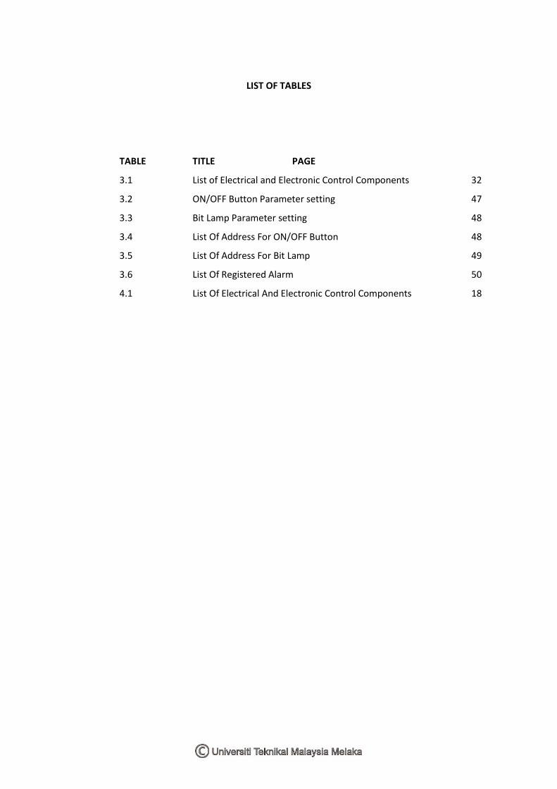
LIST OF TABLES
TABLE TITLE PAGE
3.1 List of Electrical and Electronic Control Components 32
3.2 ON/OFF Button Parameter setting 47
3.3 Bit Lamp Parameter setting 48
3.4 List Of Address For ON/OFF Button 48
3.5 List Of Address For Bit Lamp 49
3.6 List Of Registered Alarm 50
4.1 List Of Electrical And Electronic Control Components 18
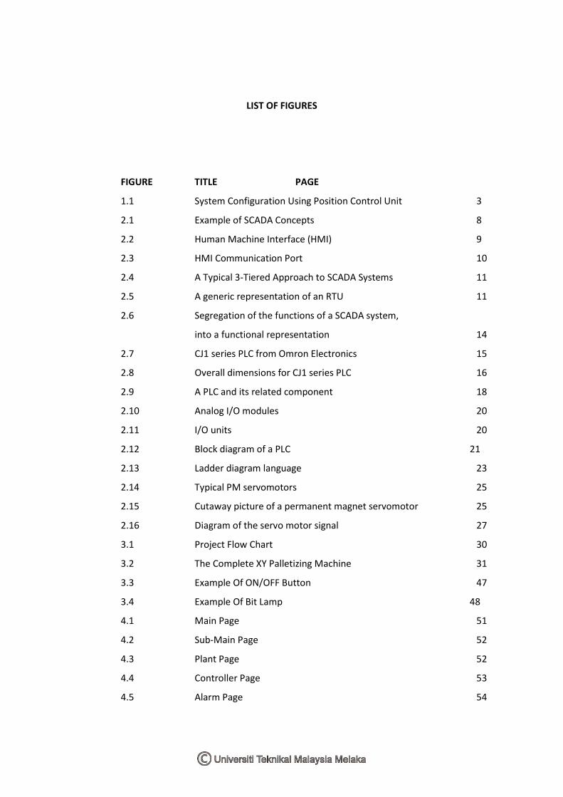
LIST OF FIGURES
FIGURE TITLE PAGE
1.1 System Configuration Using Position Control Unit 3
2.1 Example of SCADA Concepts 8
2.2 Human Machine Interface (HMI) 9
2.3 HMI Communication Port 10
2.4 A Typical 3-Tiered Approach to SCADA Systems 11
2.5 A generic representation of an RTU 11
2.6 Segregation of the functions of a SCADA system,
into a functional representation 14
2.7 CJ1 series PLC from Omron Electronics 15
2.8 Overall dimensions for CJ1 series PLC 16
2.9 A PLC and its related component 18
2.10 Analog I/O modules 20
2.11 I/O units 20
2.12 Block diagram of a PLC 21
2.13 Ladder diagram language 23
2.14 Typical PM servomotors 25
2.15 Cutaway picture of a permanent magnet servomotor 25
2.16 Diagram of the servo motor signal 27
3.1 Project Flow Chart 30
3.2 The Complete XY Palletizing Machine 31
3.3 Example Of ON/OFF Button 47
3.4 Example Of Bit Lamp 48
4.1 Main Page 51
4.2 Sub-Main Page 52
4.3 Plant Page 52
4.4 Controller Page 53
4.5 Alarm Page 54

LIST OF APPENDICES
APPENDIX TITLE PAGE
A The Complete Ladder Diagram 59
B SmartStep Servo Drive Data Sheet 64
C Position Control Unit Data Sheet 69
CHAPTER 1
INTRODUCTION
DCS is a distributed control system. It generally refers to an
industrial control system: a computer system monitoring and
controlling a process. This project will create a DCS system using
Supervisory Control and Data Acquisition (SCADA) as a base to
create GUI (Graphical user interface). The plant that will be controlled
is a servo driven position control plant. Servomotors are often use to
control sensitive adjustment such as steering, remoter and also in other
uses in robotic and positioning control system. Servo systems use a
weak control signal to move a large load to a desired position but with
great accuracy. The most suitable key words that can define these
servo mechanisms are move and great accuracy. The Smartstep servo
driver has ability to control speed, direction, acceleration and position
of servo motor. This project is been developed to view a presentable
GUI for a servo motor to pick and place process on X-axes and Y-
axes position with better process flow diagram, mimic diagram,
alarms for system diagnosis as well as other data management
systems.
1.1 Project Objective
There are two main objectives to be achieved in this project.
They are:
1. To develop a SCADA system that can be controlled
via several workstations.
2. To develop system that will include features such
as alarm, mimic diagram, process flow diagram,
thus make system more efficient and presentable.
1.2 Scope of the Project
The scope of this project will cover on:
i. The development of GUI by using Citect SCADA /
CX-Designer.
ii. The process plant controlled by PLC.
iii. Proper interfacing between hardware, software and
PLC.
1.3 Problem Statement
Presently, the process plant is the most popular industry in any
country. However, they may have encountered so many problems in
their processes. With the conventional monitoring system such as
Programmable Logic Controller (PLC), it didn‟t allow for the proper
process control management. When it comes to gather, recording and
accessing the data, the conventional system doesn‟t provide a proper
method to be implemented. Thus, it is not a user friendly system.
The DCS system that will be developed mainly used for
monitoring and it can be done remotely. The user will have the
privileges to monitor the system from outside of the plant or
somewhere else using the communication protocol available for DCS
system.
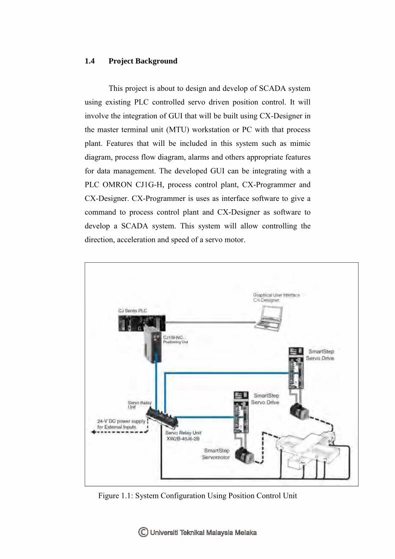
1.4 Project Background
This project is about to design and develop of SCADA system
using existing PLC controlled servo driven position control. It will
involve the integration of GUI that will be built using CX-Designer in
the master terminal unit (MTU) workstation or PC with that process
plant. Features that will be included in this system such as mimic
diagram, process flow diagram, alarms and others appropriate features
for data management. The developed GUI can be integrating with a
PLC OMRON CJ1G-H, process control plant, CX-Programmer and
CX-Designer. CX-Programmer is uses as interface software to give a
command to process control plant and CX-Designer as software to
develop a SCADA system. This system will allow controlling the
direction, acceleration and speed of a servo motor.
Figure 1.1: System Configuration Using Position Control Unit
CHAPTER 2
LITERATURE REVIEW
2.1 Distributed Control System (DCS)
The distributed control system (DCS) refers to a control
system that available in manufacturing system, process or any
kind of dynamic system, in which the controller elements are
not central in location (like the brain) but are distributed
throughout the system with each component sub-system controlled by
one or more controllers. The entire systems of controllers are
connected by networks for communication and monitoring.
DCS is a very broad term used in a variety of industries,
to monitor and control distributed equipment.
1. Electrical power grids and electrical generation plants.
2. Environmental control systems.
3. Traffic signals.
4. Water management systems.
5. Oil refining plants.
6. Chemical plant.
7. Pharmaceutical manufacturing.
8. Sensor networks.
9. Dry cargo and bulk oil carrier ships.
The classical measurement, control and actuator devices were
based on simple physical principles (mechanical, hydraulic, pneumatic
and electrical). Often they were used as stand-alone devices for
relatively closed automation solutions. With the introduction of
microprocessor technology and its fast spreading, the focus shifted
from stand-alone devices to much more complex device systems.
These systems of automation devices including their necessary
communication systems are called Process Control Systems (PCS).
Process Control Systems provide control and supervision of
production processes. They connect people (the operator) and
machines. They consist of input/output devices, data processing units,
human machine interfaces and communication systems.
First generation PCSs are characterized by a centralized
structure. A central device scans all relevant process data and computes
the actuator values. There are two basic types of PCSs, one for process
control and one for manufacturing. Their internal structures are
similar, the market (user) will decide about a possible fusion. This
fusion and the transition from centralized to de-centralized systems
based on serial communication systems (field bus) are milestones of
the development towards second generation PCSs. This development
hasn't been finished yet, but lots of solutions are emerging.
A non-interrupted engineering process on the basis of common
information models and data exchange technologies is the primary
requirement for the design of 3rd generation PCSs. These third
generation PCSs are called Distributed Control Systems (DCS) here.
2.1.1 Elements Of DCS
A DCS typically uses customs designed processors as
controllers and uses both proprietary inter connections and protocols
for communication. Input and output modules is a from component
parts of the DCS. The processor receives information from input
modules and sends information to output modules. The input modules
receive information from input instruments in the process (field) and
transmit instructions to the output instruments in the field. Computer
buses or electrical buses connect the processor and modules through
multiplexers or demultiplexers. Buses also connect the distributed
controllers with the central controller and finally to the Human
Machine Interface (HMI) or control consoles. Elements of a
distributed control system may directly connect to physical equipment
such as switches, pumps and valves or may work through an
intermediate system such as a SCADA system.
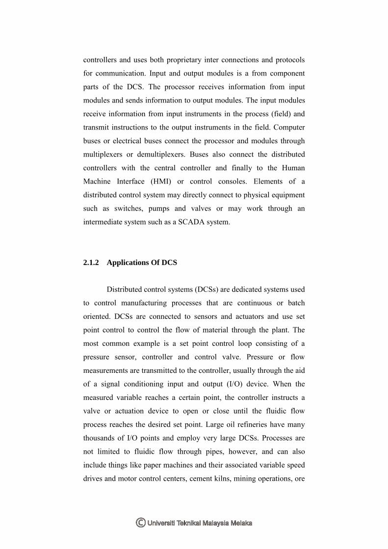
2.1.2 Applications Of DCS
Distributed control systems (DCSs) are dedicated systems used
to control manufacturing processes that are continuous or batch
oriented. DCSs are connected to sensors and actuators and use set
point control to control the flow of material through the plant. The
most common example is a set point control loop consisting of a
pressure sensor, controller and control valve. Pressure or flow
measurements are transmitted to the controller, usually through the aid
of a signal conditioning input and output (I/O) device. When the
measured variable reaches a certain point, the controller instructs a
valve or actuation device to open or close until the fluidic flow
process reaches the desired set point. Large oil refineries have many
thousands of I/O points and employ very large DCSs. Processes are
not limited to fluidic flow through pipes, however, and can also
include things like paper machines and their associated variable speed
drives and motor control centers, cement kilns, mining operations, ore
processing facilities and many others.
A typical DCS consists of functionally and/or geographically
distributed digital controllers capable of executing from 1 to 256 or
more regulatory control loops in one control box. The I/O devices can
be integral with the controller or located remotely via a field network.
Today‟s controllers have extensive computational capabilities and in
addition to proportional, integral and derivative (PID) control, can
generally perform logic and sequential control.
DCSs may employ one or several workstations and can be
configured at the workstation or by an off-line personal computer.
Local communication is handled by a control network with
transmission over twisted pair, coaxial or fiber optic cable. A server
and/or applications processor may be included in the system for extra
computational, data collection and reporting capability.
2.2 Supervisory Control And Data Acquisition (SCADA)
SCADA is the abbreviation for Supervisory Control And Data
Acquisition. It generally refers to an industrial control system: a
computer system monitoring and controlling a process. The process
can be industrial, infrastructure or facility based as described below:
1. Industrial processes include those of manufacturing,
production, power generation, fabrication and refining,
and may run in continuous, batch, repetitive or discrete
modes.
2. Infrastructure processes may be public or private, and
include water treatment and distribution, wastewater
collection and treatment, oil and gas pipelines, electrical
power transmission and distribution and large
communication systems.
3. Facility processes occur both in public facilities
and private ones. They monitor and control HVAC,
access and energy consumption.
A SCADA System usually consists of the following subsystems:
1. A Human-Machine Interface (HMI) is the
apparatus which presents process data to a human
operator and through which the human operator
monitors and controls the process.
2. A supervisory (computer) system, gathering
(acquiring) data on the process and sending
commands (control) to the process
3. Remote Terminal Units (RTUs) connecting to
sensors in the process, converting sensor signals to
digital data and sending digital data to the
supervisory system.
4. Communication infrastructure connecting the
supervisory system to the Remote Terminal Units.
There is, in several industries, considerable confusion
over the differences between SCADA systems and
Distributed control systems (DCS). Generally speaking, a
SCADA system usually refers to a system that coordinates.
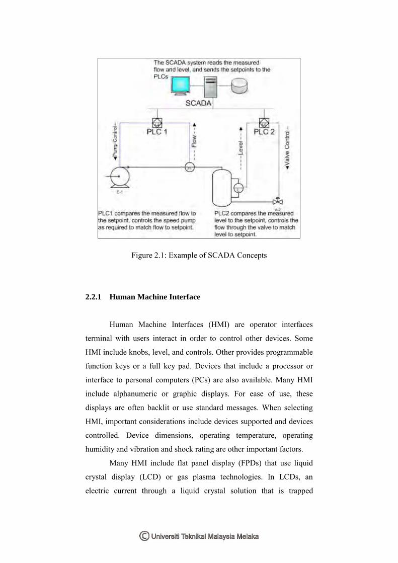
Figure 2.1: Example of SCADA Concepts
2.2.1 Human Machine Interface
Human Machine Interfaces (HMI) are operator interfaces
terminal with users interact in order to control other devices. Some
HMI include knobs, level, and controls. Other provides programmable
function keys or a full key pad. Devices that include a processor or
interface to personal computers (PCs) are also available. Many HMI
include alphanumeric or graphic displays. For ease of use, these
displays are often backlit or use standard messages. When selecting
HMI, important considerations include devices supported and devices
controlled. Device dimensions, operating temperature, operating
humidity and vibration and shock rating are other important factors.
Many HMI include flat panel display (FPDs) that use liquid
crystal display (LCD) or gas plasma technologies. In LCDs, an
electric current through a liquid crystal solution that is trapped
between two sheets or polarizing material. The crystals align
themselves so that light cannot pass, producing an image on the
screen. LCDs can be monochrome or color. Color display can use a
passive matrix or an active matrix.
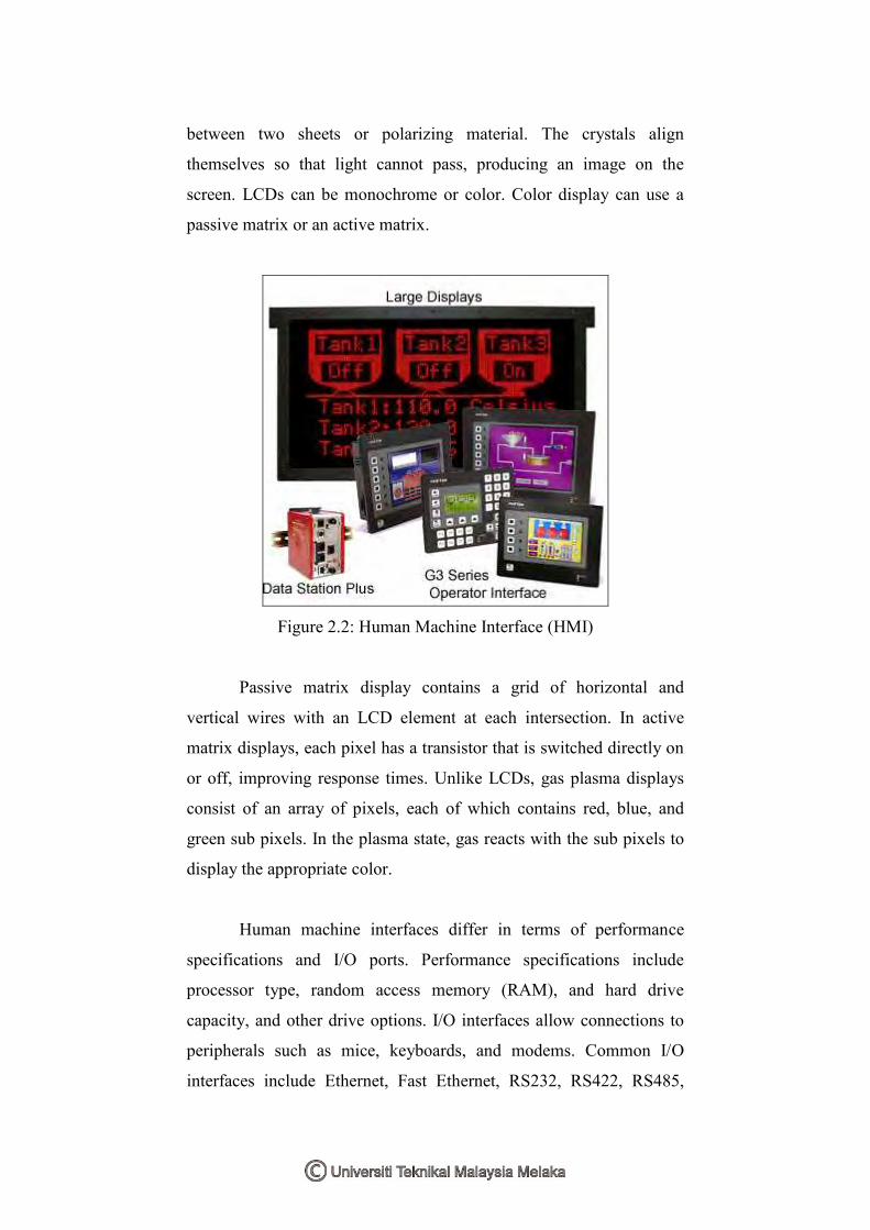
Figure 2.2: Human Machine Interface (HMI)
Passive matrix display contains a grid of horizontal and
vertical wires with an LCD element at each intersection. In active
matrix displays, each pixel has a transistor that is switched directly on
or off, improving response times. Unlike LCDs, gas plasma displays
consist of an array of pixels, each of which contains red, blue, and
green sub pixels. In the plasma state, gas reacts with the sub pixels to
display the appropriate color.
Human machine interfaces differ in terms of performance
specifications and I/O ports. Performance specifications include
processor type, random access memory (RAM), and hard drive
capacity, and other drive options. I/O interfaces allow connections to
peripherals such as mice, keyboards, and modems. Common I/O
interfaces include Ethernet, Fast Ethernet, RS232, RS422, RS485,