Embed Size (px)
Citation preview
1
Development of Direct Write Ink Jet for Deposition of Silver Contacts
Lee SmithDepartment of Energy – Energy Research Undergraduate Laboratory Fellowship
ProgramUniversity of California, Santa Cruz
National Renewable Energy LaboratoryGolden, Colorado
July 26, 2001
Prepared in partial fulfillment of the requirements of the Department of Energy ERULFProgram under the direction of David Ginley at the National Renewable Energy
Laboratory.
Participant:Signature
Research Advisor:Signature

2
Table of Contents
Abstract 3
Introduction 4
Methods and Materials 7
Results 10
Discussion and Conclusion 13
Acknowledgements 14
References 15
Figures and Diagrams 16
3
Abstract
Development of Direct Write Ink Jet for Deposition of SilverContacts. LEE SMITH (University of California, Santa Cruz,95064) Tanya Rivkin (National Renewable Energy Laboratory,Golden, CO 80401).
This project investigated the direct write printing of inks for Agmetallizations and polymer absorbers for solar cells. The basicthrust is to develop an integrated ink jet system capable of versatileprinting with a variety of inks. We successfully developed a newprinting system and printed Ag inks and attempted to printpolymer-based inks.
Category (circle one): Material Science -- Engineering -- Computer Science
School Author Attends: University of California, Santa CruzDOE National Laboratory Attended: National Renewable Energy LaboratoryMentor’s Name: Tanya RivkinPhone: (303) 384-6430Email: [email protected]
Presenter’s Name: Lee SmithMailing Address:
142 Bixby StreetSanta Cruz, CA95060
Phone: (831) 421-9321E-mail: [email protected]
4
Introduction
Motivation
An ongoing mission in the commercial photovoltaic industry is to reduce the cost
of production while maintaining or increasing the efficiency of solar cells. Ink jet printing
is a direct write approach to deposition of various electronic materials that has the
potential to reduce the cost of solar cell processing. It may also be a critical technology
for the development of next generation polymer solar cells. Since liquid precursors or
inks of many of these polymers can be made, it may thus be possible to print entire solar
cells with an ink jet which should reduce production cost and complexity and materials
waste. In addition to being a useful tool for the development of the next generation
photovoltaics, ink jet printing may also have a significant impact on conventional Si solar
cell technology that at present dominates the market.
Currently, screen printing and vacuum deposition are the two major techniques
used by the solar cell industry to deposit silver contacts. Vacuum deposition is capital
intensive and hard to integrate in process streams. Screen printing is current standard for
commercial manufacturing of many solar cells, though lower cost it has the drawbacks of
low resolution, materials waste, and being a contact approach. Ink jet printing offers an
alternative to both of these methods that is cheaper and could produce more efficient cells
because of higher resolution and is non-contact with no additional patterning required.
Ink jets have three distinct advantages over the standard screen printing technique.
First, ink jets offer the possibility of increased resolution. Screen printing is limited to
about 100 micron resolution, but ink jets have the potential of increasing the resolution to
less than 20 microns (Rivkin et al., 2001). Increased resolution leads to higher efficiency
5
cells because of less shadowing. Second, ink jet printing, is a non-contact deposition
technique, which is ideal for processing thin and fragile substrates. In order to reduce the
material costs and improve performance, the photovoltaic industry is tending to use
thinner substrates. They are trying to go below 100µm for cell thickness. These thinner
substrates often break under the screen printing process. Third, ink jets are a direct write
technology; they only print ink where ink is desired eliminating photolithographic
process and allowing flexibility on the fly. In contrast to this, screen printing requires the
ink to be spread over a large screen. While some ink can be reused, a significant amount
dries on the screen and is wasted. Also, as a result of the ink drying, the screens should
be often cleaned and replaced, which ads to the overall cost of the process. If ink jets
replaced screen printing, the overall cost of manufacturing could be significantly reduced.
Background
Modern ink jets are capable of generating small sized (less than 20 micron) drops.
Liquid precursors of electronic materials can be printed with an ink jet to produce various
components for medium resolution solid-state devices. There are several approaches to
formulating these liquid precursors. They can be composed of dissolved organometallic
compounds or polymers, colloidal suspensions of nanoparticles, or some combination of
these constituents. Using organometallic inks, the desired material is formed upon
thermal decomposition of the organometallic molecule which contains the atom or atoms
of interest in the final materials. It is important that all of the organic constituents be
volatile so that only the pure desired materials are formed. For example, a pure silver
film was produced from silver(hexafluoroacetylacetonate)(1,5-cyclooctadiene) or
Ag(hfa)(COD) dissolved in an organic solvent by spray deposition on a heated substrate
6
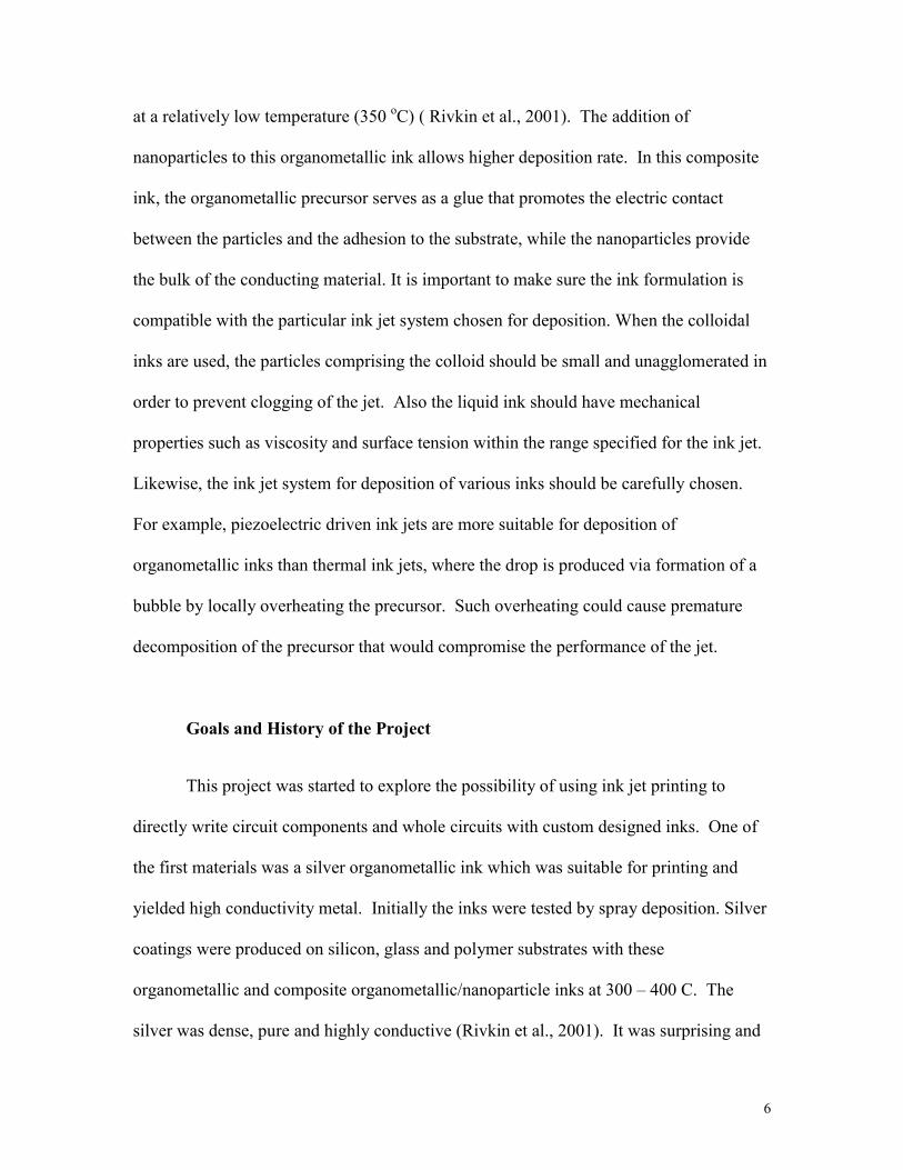
at a relatively low temperature (350 oC) ( Rivkin et al., 2001). The addition of
nanoparticles to this organometallic ink allows higher deposition rate. In this composite
ink, the organometallic precursor serves as a glue that promotes the electric contact
between the particles and the adhesion to the substrate, while the nanoparticles provide
the bulk of the conducting material. It is important to make sure the ink formulation is
compatible with the particular ink jet system chosen for deposition. When the colloidal
inks are used, the particles comprising the colloid should be small and unagglomerated in
order to prevent clogging of the jet. Also the liquid ink should have mechanical
properties such as viscosity and surface tension within the range specified for the ink jet.
Likewise, the ink jet system for deposition of various inks should be carefully chosen.
For example, piezoelectric driven ink jets are more suitable for deposition of
organometallic inks than thermal ink jets, where the drop is produced via formation of a
bubble by locally overheating the precursor. Such overheating could cause premature
decomposition of the precursor that would compromise the performance of the jet.
Goals and History of the Project
This project was started to explore the possibility of using ink jet printing to
directly write circuit components and whole circuits with custom designed inks. One of
the first materials was a silver organometallic ink which was suitable for printing and
yielded high conductivity metal. Initially the inks were tested by spray deposition. Silver
coatings were produced on silicon, glass and polymer substrates with these
organometallic and composite organometallic/nanoparticle inks at 300 – 400 C. The
silver was dense, pure and highly conductive (Rivkin et al., 2001). It was surprising and
7
encouraging that these coatings demonstrated adhesion to Silicon that was superior to that
of the screen-printed films. As a second step the organometallic inks were tested with a
commercial Epson ink jet printer that was modified to allow printing on a heated
substrate. The silver ink our team had developed had different physical properties such as
viscosity and evaporation rate from the water based inks conventionally used in Epson
ink jet printers. While the printer did produce testable silver depositions, it did not allow
optimization of printing conditions for our customized inks, which resulted in low
resolution of the printed patterns.
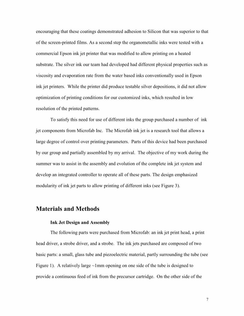
To satisfy this need for use of different inks the group purchased a number of ink
jet components from Microfab Inc. The Microfab ink jet is a research tool that allows a
large degree of control over printing parameters. Parts of this device had been purchased
by our group and partially assembled by my arrival. The objective of my work during the
summer was to assist in the assembly and evolution of the complete ink jet system and
develop an integrated controller to operate all of these parts. The design emphasized
modularity of ink jet parts to allow printing of different inks (see Figure 3).
Materials and Methods
Ink Jet Design and Assembly
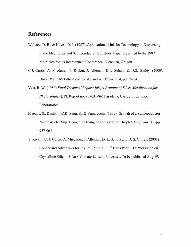
The following parts were purchased from Microfab: an ink jet print head, a print
head driver, a strobe driver, and a strobe. The ink jets purchased are composed of two
basic parts: a small, glass tube and piezoelectric material, partly surrounding the tube (see
Figure 1). A relatively large ~1mm opening on one side of the tube is designed to
provide a continuous feed of ink from the precursor cartridge. On the other side of the
8
tube, the internal diameter reduces to 50 microns. This end determines the size of the
drops formed. When a voltage pulse is applied to the piezoelectric crystal, it contracts,
generating a hydraulic transient pressure pulse or aquatic sound pulse, which ejects a
drop of liquid out of the tip (Wallace & Hayes, 1987).
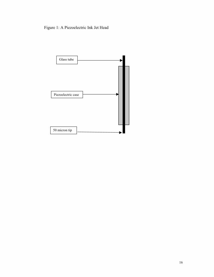
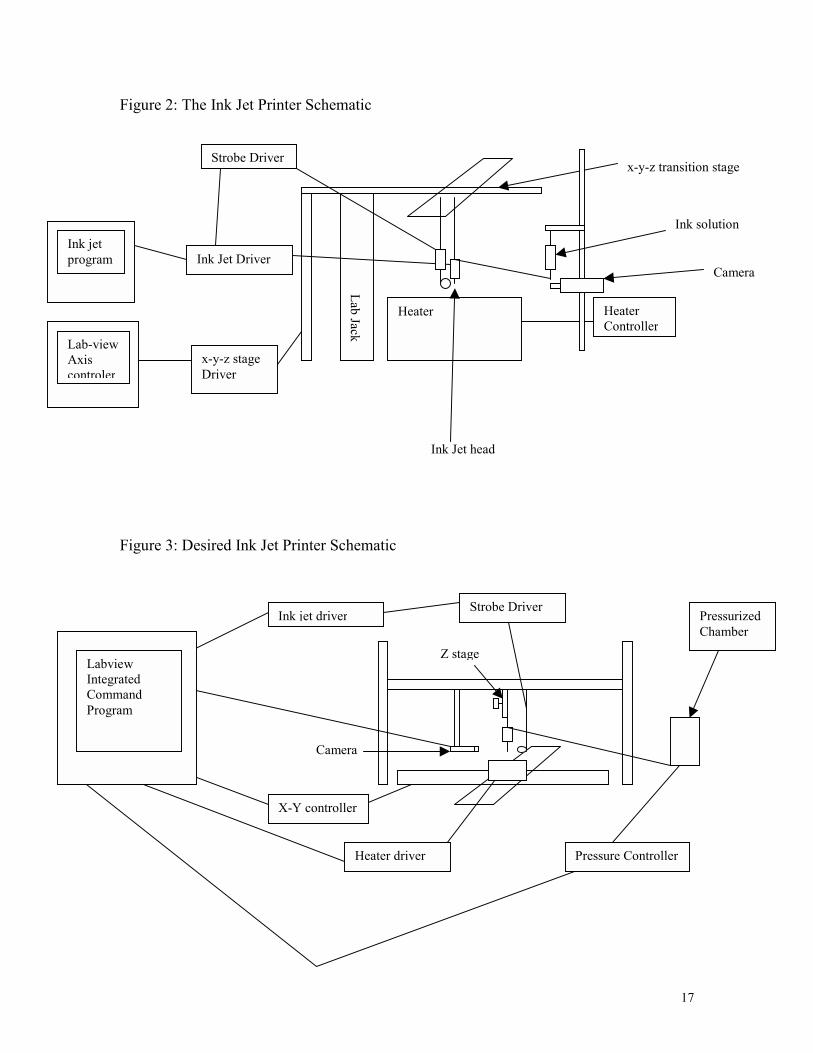
First, a test printer was constructed with the above parts and a used x-y-z
transition stage and heater. The printer was mounted such that the jet was suspended
from the x-y transition stage of the substrate heater. The jet was then moved physically
in the x-y plane and was controlled by an Apple computer (see Figure 2). The z-axis was
not operational and was controlled by a lab jack. A large heating plate was mounted
under the X-Y stage that heated the substrate. The Microfab Jetdrive III driver interfaced
between the ink jet head and a 486 laptop. When initiated by computer command, it
sends a voltage pulse to the piezoelectric that triggers drop ejection ( Figure 7). The
advised voltage pulse shape from the manual was used. It consisted of a positive pulse of
variable length and amplitude followed by a negative pulse of the same amplitude but
two times the length. The ink was suspended in a syringe from a rod slightly higher than
the ink head and connected via a tube to the ink jet. An analog camcorder with external
lenses was used to observe the ink jet. This first generation printer was assembled as
quickly as possible to test the general design before a heater and expensive high precision
x-y transition stage were purchased. Hence, care was not taken to make the original
printer an easy to use system. This initial testing allowed us to conclude that the movable
jet approach is not optimal since the “artificial” wind produced during the motion of the
head altered the conditions the jet was optimized for and caused jet instability.
9
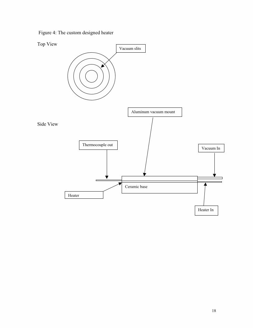
The next generation ink jet system was constructed with a stationary jet and the
new one micron resolution x-y transition stages that were mounted on an optical table
(see Figure 3). A new custom heater was mounted on top of this stage. It was composed
of an aluminum vacuum mount and insulating ceramic base (see Figure 4). This heater
was attached to the transition stage and the ink jet was fixed vertically above it. A 3com
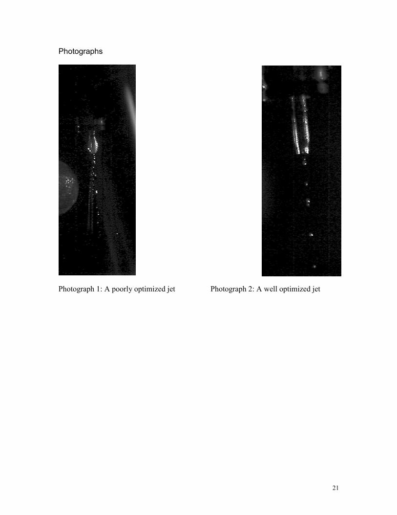
HomeConnect Camera with a custom zoom lens was mounted to observe the ink jet. The
strobe light illuminating the jet was positioned near the print head synchronized to the ink
jet pulse. This setup allowed stop action imaging of the jet drops as in Photographs 1 and
2.
I developed a new Labview control program to control the x-y transition stage.
The program works by taking the desired location and movement specifications inputted
by a researcher and generates a series of machine commands, which are then written to
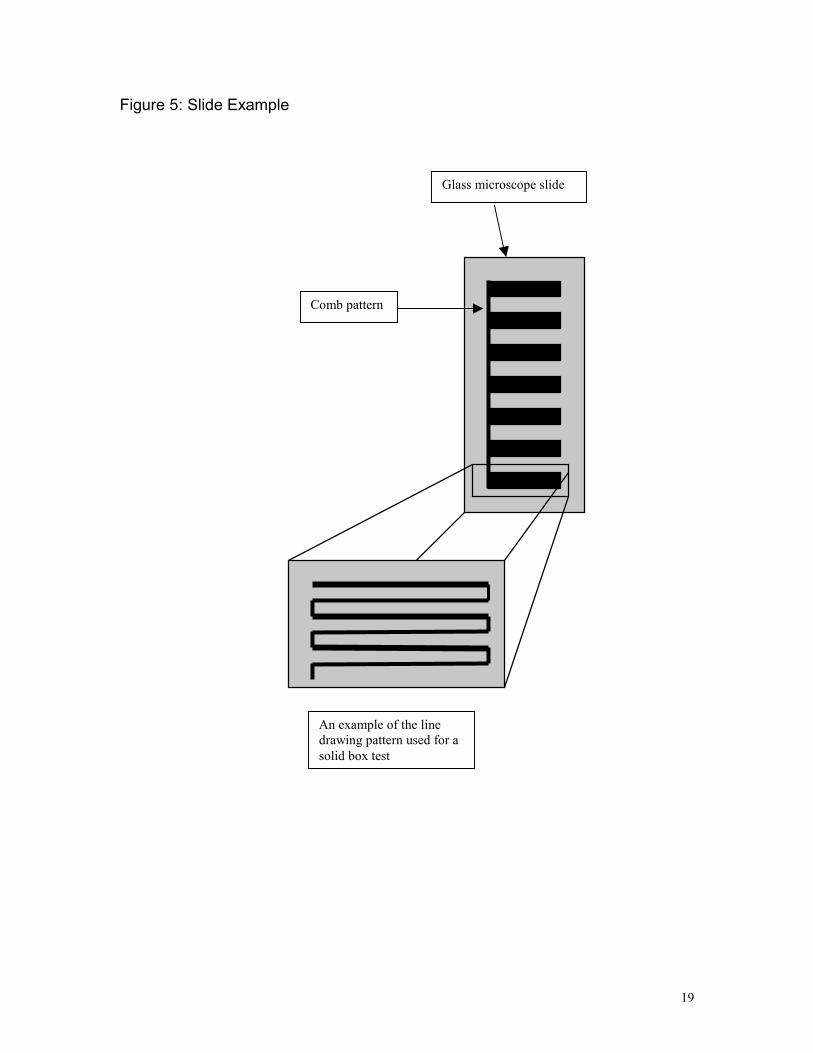
the x-y stage through a GPIB/ IEEE interface. I chose a comb-shaped test pattern to
allow the optimization of both line and solid shape printing. The comb pattern prints a
series of teeth. With each tooth a major printing parameter such as the speed of x-y table,
number of lines per tooth, separation between the lines, number of layers, and time delay
between layers can be incremented (see Figure 6). This allows the researcher to perform
combinatorial studies, which accelerates research, and can more easily show trends. The
operation of this complex program is greatly simplified with a user-friendly interface,
which allows the execution of customizable presets with the click of a button. In
addition, each experiment is automatically logged into a file, which can be easily
accessed, edited and printed in the control program. This frees the researcher from
logging the many parameters by hand.
10
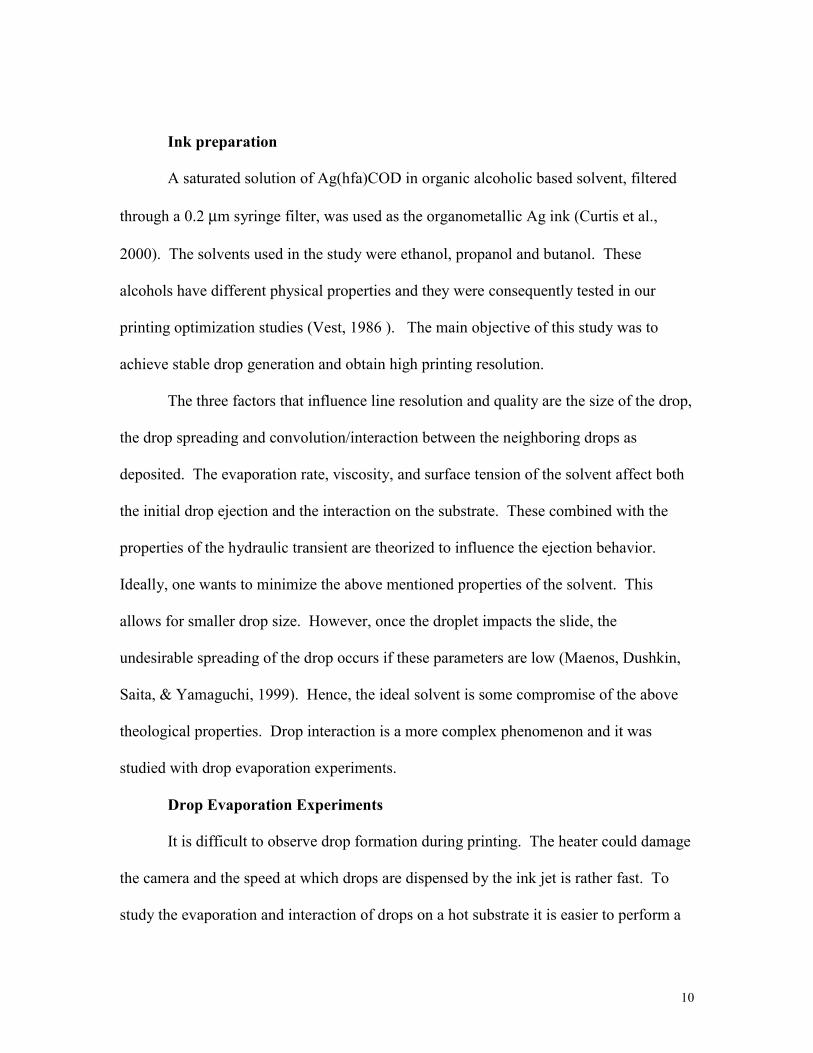
Ink preparation
A saturated solution of Ag(hfa)COD in organic alcoholic based solvent, filtered
through a 0.2 µm syringe filter, was used as the organometallic Ag ink (Curtis et al.,
2000). The solvents used in the study were ethanol, propanol and butanol. These
alcohols have different physical properties and they were consequently tested in our
printing optimization studies (Vest, 1986 ). The main objective of this study was to
achieve stable drop generation and obtain high printing resolution.
The three factors that influence line resolution and quality are the size of the drop,
the drop spreading and convolution/interaction between the neighboring drops as
deposited. The evaporation rate, viscosity, and surface tension of the solvent affect both
the initial drop ejection and the interaction on the substrate. These combined with the
properties of the hydraulic transient are theorized to influence the ejection behavior.
Ideally, one wants to minimize the above mentioned properties of the solvent. This
allows for smaller drop size. However, once the droplet impacts the slide, the
undesirable spreading of the drop occurs if these parameters are low (Maenos, Dushkin,
Saita, & Yamaguchi, 1999). Hence, the ideal solvent is some compromise of the above
theological properties. Drop interaction is a more complex phenomenon and it was
studied with drop evaporation experiments.
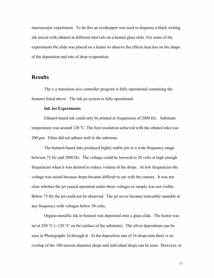
Drop Evaporation Experiments
It is difficult to observe drop formation during printing. The heater could damage
the camera and the speed at which drops are dispensed by the ink jet is rather fast. To
study the evaporation and interaction of drops on a hot substrate it is easier to perform a
11
macroscopic experiment. To do this an eyedropper was used to dispense a black writing
ink mixed with ethanol at different intervals on a heated glass slide. For some of the
experiments the slide was placed on a heater to observe the effects heat has on the shape
of the deposition and rate of drop evaporation.
Results
The x-y transition axis controller program is fully operational containing the
features listed above. The ink jet system is fully operational.
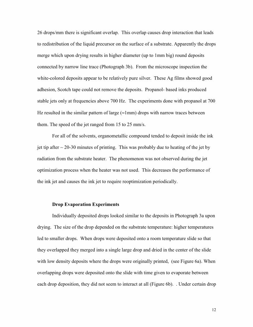
Ink Jet Experiments
Ethanol-based ink could only be printed at frequencies of 2000 Hz. Substrate
temperature was around 120 oC. The best resolution achieved with the ethanol inks was
200 µm. Films did not adhere well to the substrate.
The butanol-based inks produced highly stable jets in a wide frequency range
between 75 Hz and 2000 Hz. The voltage could be lowered to 20 volts at high enough
frequencies when it was desired to reduce volume of the drops. At low frequencies the
voltage was raised because drops became difficult to see with the camera. It was not
clear whether the jet ceased operation under these voltages or simply was not visible.
Below 75 Hz the jet could not be observed. The jet never became noticeably unstable at
any frequency with voltages below 30 volts.
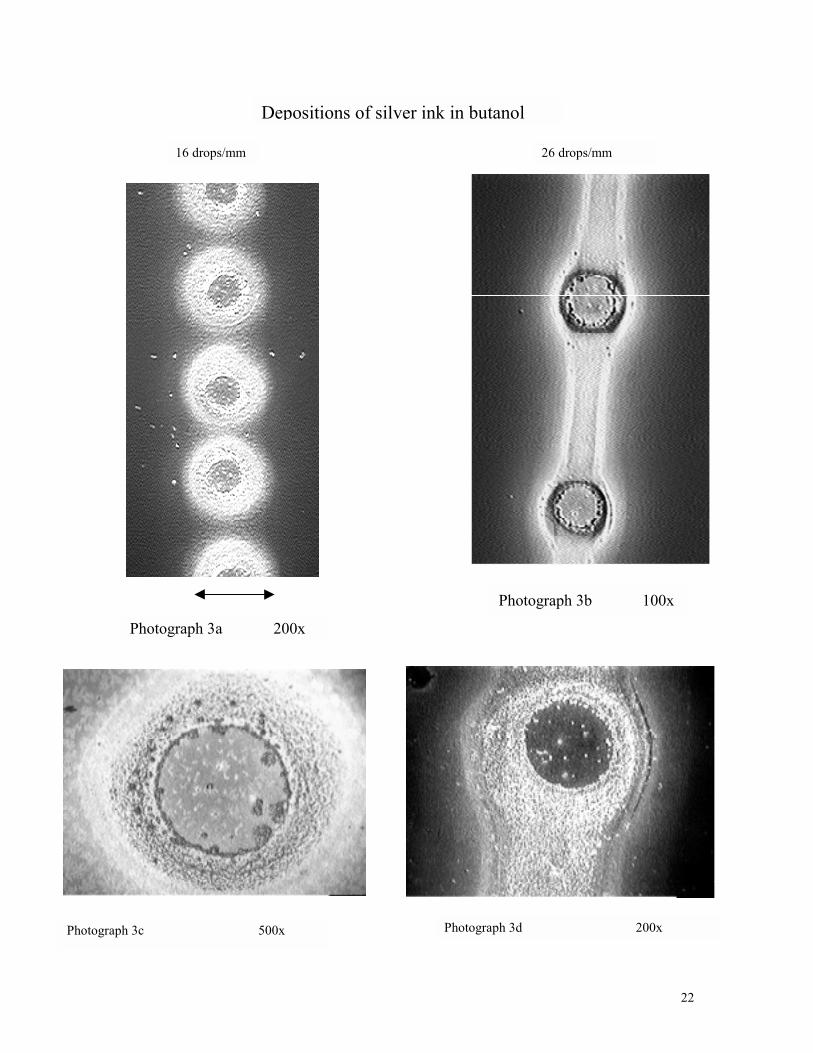
Organo-metallic ink in butanol was deposited onto a glass slide. The heater was
set at 250 °C (~120 °C on the surface of the substrate). The silver depositions can be
seen in Photographs 3a through d. At the deposition rate of 16 drops/mm there is no
overlap of the 100-micron diameter drops and individual drops can be seen. However, at
12
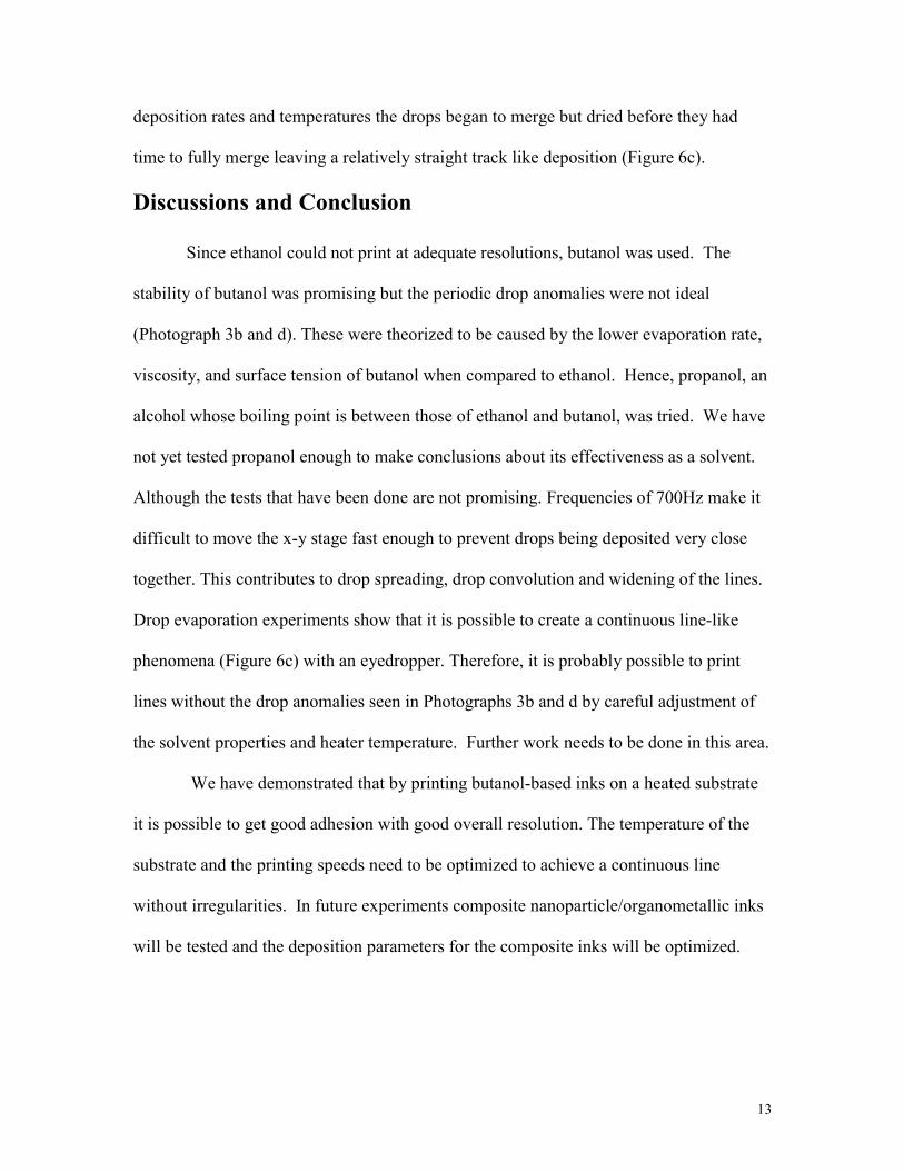
26 drops/mm there is significant overlap. This overlap causes drop interaction that leads
to redistribution of the liquid precursor on the surface of a substrate. Apparently the drops
merge which upon drying results in higher diameter (up to 1mm big) round deposits
connected by narrow line trace (Photograph 3b). From the microscope inspection the
white-colored deposits appear to be relatively pure silver. These Ag films showed good
adhesion, Scotch tape could not remove the deposits. Propanol- based inks produced
stable jets only at frequencies above 700 Hz. The experiments done with propanol at 700
Hz resulted in the similar pattern of large (≈1mm) drops with narrow traces between
them. The speed of the jet ranged from 15 to 25 mm/s.
For all of the solvents, organometallic compound tended to deposit inside the ink
jet tip after ~ 20-30 minutes of printing. This was probably due to heating of the jet by
radiation from the substrate heater. The phenomenon was not observed during the jet
optimization process when the heater was not used. This decreases the performance of
the ink jet and causes the ink jet to require reoptimization periodically.
Drop Evaporation Experiments
Individually deposited drops looked similar to the deposits in Photograph 3a upon
drying. The size of the drop depended on the substrate temperature: higher temperatures
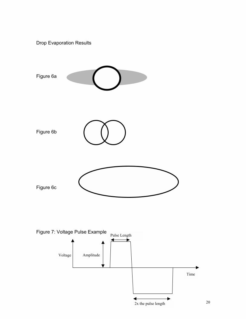
led to smaller drops. When drops were deposited onto a room temperature slide so that
they overlapped they merged into a single large drop and dried in the center of the slide
with low density deposits where the drops were originally printed, (see Figure 6a). When
overlapping drops were deposited onto the slide with time given to evaporate between
each drop deposition, they did not seem to interact at all (Figure 6b). . Under certain drop
13
deposition rates and temperatures the drops began to merge but dried before they had
time to fully merge leaving a relatively straight track like deposition (Figure 6c).
Discussions and Conclusion
Since ethanol could not print at adequate resolutions, butanol was used. The
stability of butanol was promising but the periodic drop anomalies were not ideal
(Photograph 3b and d). These were theorized to be caused by the lower evaporation rate,
viscosity, and surface tension of butanol when compared to ethanol. Hence, propanol, an
alcohol whose boiling point is between those of ethanol and butanol, was tried. We have
not yet tested propanol enough to make conclusions about its effectiveness as a solvent.
Although the tests that have been done are not promising. Frequencies of 700Hz make it
difficult to move the x-y stage fast enough to prevent drops being deposited very close
together. This contributes to drop spreading, drop convolution and widening of the lines.
Drop evaporation experiments show that it is possible to create a continuous line-like
phenomena (Figure 6c) with an eyedropper. Therefore, it is probably possible to print
lines without the drop anomalies seen in Photographs 3b and d by careful adjustment of
the solvent properties and heater temperature. Further work needs to be done in this area.
We have demonstrated that by printing butanol-based inks on a heated substrate
it is possible to get good adhesion with good overall resolution. The temperature of the
substrate and the printing speeds need to be optimized to achieve a continuous line
without irregularities. In future experiments composite nanoparticle/organometallic inks
will be tested and the deposition parameters for the composite inks will be optimized.

14
Acknowledgements
I thank NREL and the Department of Energy for giving me the opportunity to
acquire hands on experience in the lab. I would especially like to thank my mentor,
Tanya Rivkin as well as Alexander Miedaner. They were very encouraging and
supportive as well as insightful and fun. Also, thanks to John Perkins, Garry Rumbles,
and Howard Branz. I would like I would also like to thank David Ginley, our team
leader, for his excellent leadership. It is an inspiration to know that people like these are
working to develop sustainable energy sources.
15
References
Wallace, D. B., & Hayes, D. J. (1987). Application of Ink Jet Technology to Dispensing
in the Electronics and Semiconductor Industries. Paper presented to the 1987
Microelectronics Interconnect Conference, Gleneden, Oregon.
C.J. Curtis, A. Miedaner, T. Rivkin, J. Alleman, D.L. Schulz, & D.S. Ginley. (2000).
Direct Write Metallizations for Ag and Al. Mater, 624, pp. 59-64.
Vest, R. W. (1986) Final Technical Report: Ink jet Printing of Silver Metallization for
Photovoltaics (JPL Report no. 957031-86) Pasadena, CA: Jet Propulsion
Laboratories.
Maenos, S., Dushkin, C.D.,Saita, S., & Yamaguchi. (1999). Growth of a Semiconductor
Nanoparticle Ring during the Drying of a Suspension Droplet. Langmuir, 15, pp.
957-965.
T. Rivkin, C. J. Curtis, A. Miedaner, J. Alleman, D. L. Schulz and D. S. Ginley. (2001)
Copper and Silver Inks for Ink Jet Printing. 11th Estes Park, CO: Workshop on
Crystalline Silicon Solar Cell materials and Processes. To be published Aug 19.
16
Figure 1: A Piezoelectric Ink Jet Head
Glass tube
Piezoelectric case
50 micron tip
17
Figure 2: The Ink Jet Printer Schematic
Figure 3: Desired Ink Jet Printer Schematic
Lab Jack
Ink Jet DriverInk jetprogram
Lab-viewAxiscontroler
x-y-z stageDriver
HeaterController
Heater
x-y-z transition stage
Ink solution
Ink Jet head
Strobe Driver
Camera
Z stageLabviewIntegratedCommandProgram
X-Y controller
Ink jet driver
Heater driver
Camera
Strobe Driver
Pressure Controller
PressurizedChamber
18
Figure 4: The custom designed heater
Top View
Side View
Heater
Aluminum vacuum mount
Ceramic base
Thermocouple outVacuum In
Heater In
Vacuum slits
19
Figure 5: Slide Example
Glass microscope slide
Comb pattern
An example of the linedrawing pattern used for asolid box test
20
Drop Evaporation Results
Figure 6a
Figure 6b
Figure 6c
Figure 7: Voltage Pulse Example
Voltage
Pulse Length
2x the pulse length
Amplitude
Time
21
Photographs
Photograph 1: A poorly optimized jet Photograph 2: A well optimized jet
22
16 drops/mm 26 drops/mm
Photograph 3a 200x
Photograph 3b 100x
Photograph 3c 500x Photograph 3d 200x
Depositions of silver ink in butanol

23