Embed Size (px)
Citation preview

Development of database and guidelines for the
earthquake resistant design of cantilever
retaining walls
A. M. Harraz, A. Fafitis, and W. N. HoustonDepartment of Civil and Environmental Engineering, Arizona StateUniversiy, USA.
Abstract
In recent years there have been several failures of retaining walls duringearthquakes, suggesting that these structures were not designed for seismicloading or that the dynamic earth pressure exerted on such structures aredifferent horn those assumed by traditional theories. Current practice for theearthquake design of retaining walls is generally based on design rulessuggested in a comprehensive paper by Seed and Whitman. However there aresome indications that these rules may be unconservative for cantilever walls.The primary objective of this paper is to study the effect of the main designparameters on the elastic and plastic deflection of concrete cantilever retainingwalls, under undamped seismic loading. The design parameters studied in thispaper are the soil angle of internal friction, the modulus of the soil, the fictionalcoefilcient between the wall and the soil, and the coefficient of at-rest lateralearth pressure, and the type of earthquake record (exciting motion). To evaluatethe behavior of the wall under seismic loads, a finite element model has beendeveloped (using ABAQUS), and the time histories of the vertical normalstresses and moments at critical sections of the wall has been studied. Aparametric study has been conducted to develop a database and guidelines forthe design of reinforced concrete cantilever retaining walls against seismicloads,
Introduction
Earth retaining structures, such as retaining wall, bridge abutments, quay walls,anchored bulkheads, braced excavations, and mechanically stabilized walls, areused throughout seismically active areas. They frequently represent keyelements of ports and harbors, transportation systems, lifelines, and otherconstructed facilities. Excessive dynamic lateral earth pressure on retaining
© 2002 WIT Press, Ashurst Lodge, Southampton, SO40 7AA, UK. All rights reserved.Web: www.witpress.com Email [email protected] from: Structures Under Shock and Impact VII, N Jones, CA Brebbia and AM Rajendran (Editors).ISBN 1-85312-911-9
346 .Y[rl[’,tl(rcsi ‘ridershock and [mpact f ‘[i
structures resulting from earthquakes induces sliding and/or tilting to theretaining structures, Strong earthquakes usually cause permanent deformationsof retaining structures. In some cases, these deformations are small; in othersthey may cause significant damage. In some cases, retaining structures havecollapsed during earthquakes, with disastrous physical and economicconsequences. Retaining walls are often classified, depending on their mass,flexibility, and anchorage conditions, as gravity walls, cantilever walls, andtieback walls. Cantilever walls are probably the most common and they are usedto support bridges and backtlll soil. Cantilever walls are the subject of thispaper,
Finite Element Method (l?.E.M.)
A design method based on the concept of limited earthquake-induceddisplacement of the wall, was originally proposed by Richard and Ehns [1,2]. Itis believed to give fairly accurate estimates of the displacement. This methodtakes into account the effect of wall inertia which is not taken into account inother methods such as the Mononobe-Okabe Method (M-O) [3]. The basic ideaof the Richard and Elms method is that the walls fail during an earthquake in anincremental pattern, It assumes a displacement pattern similar to the Newmarksliding block analogy [4].The earthquake induced pressures on retaining wallscan be evaluated by a number of computer programs using linear or equivalentlinear analysis, Also, a nonlinear analysis can be used to evaluate permanentdeformations as well as wall pressures. Nadirn and Whitman [2,3] haveproposed a two-dimensional finite element model (N-W model) which iscapable of taking into account amplifications of ground motion in the soil wedge[5,6]. The model incorporates slip elements along planes where slip is expectedto occur. The slip planes are located along the backfill-wall interface, at the baseof the wall and along a failure plane through the backfill. Elastic perfectlyplastic behavior for the slip elements is assumed. Over estimation ofdisplacement with (N-W) finite element model is believed to be due to theoccurrence of resonance [7].
Soil-Wall Configuration
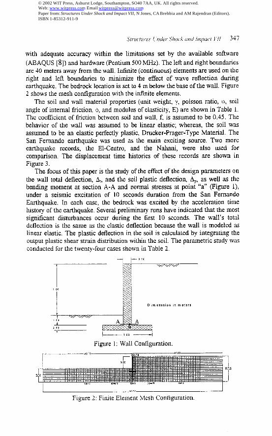
The objective of this work is to study the effect of the following designparameters on the seismic behavior of cantilever walls: soil angle of internalfriction, $, soil modulus of elasticity, E, coefficient of friction between soil andwall, f, coefficient of Iater,al at-rest pressure, ~, ,and earthquake record. Theretaining wall shown’in Figure 1 was used for the study. The wall height is 6mabove the base with a clear height of 5 m. The base width is 3 m giving a ratio ofbase width to wall height of 0.5. The wall and base thicknesses are 0.50 m asshown in Figure 1. The mesh was determined by several preliminary runs. Inthis mesh, the soil and wall were discretized, The trial mesh configurationshown in Figure 2 can capture the behavior of the wall and the surrounding soil
© 2002 WIT Press, Ashurst Lodge, Southampton, SO40 7AA, UK. All rights reserved.Web: www.witpress.com Email [email protected] from: Structures Under Shock and Impact VII, N Jones, CA Brebbia and AM Rajendran (Editors).ISBN 1-85312-911-9
Strmtmes 1underShock and Impact i 11 347
with adequate accuracy within the limitations set by the available software
(ABAQUS [8]) and hardware (Pentium 500 MHz). The left and right boundariesare 40 meters away from the wall, Infinite (continuous) elements are used on theright and Ietl boundaries to minimize the effect of wave reflection duringearthquake, The bedrock location is set to 4 m below the base of the wall. Figure2 shows the mesh configuration with the infinite elements.
The soil and wall material properties (unit weight, y, poisson ratio, u, soilangle of internal friction, +, and modulus of elasticity, E) are shown in Table 1.The coefficient of friction between soil and wall, f, is assumed to be 0.45. Thebehavior of the wall was assumed to be linear elastic; whereas, the soil wasassumed to be an elastic perfectly plastic, Drucker-Prager-Type Material. TheSan Fernando earthquake was used as the main exciting source. Two moreearthquake records, the E1-Centro, and the Nahani, were also used forcomparison. The displacement time histories of these records are shown inFigure 3.
The focus of this paper is the study of the effect of the design parameters onthe wall total deflection, AL,and the soil plastic deflection, AP, as well as thebending moment at section A-A and normal stresses at point “a” (Figure 1),under a seismic excitation of 10 seconds duration from the San FernandoEarthquake. In each case, the bedrock was excited by the acceleration timehistory of the earthquake. Several preliminary runs have indicated that the mostsignificant disturbances occur during the first 10 seconds. The wall’s totaldeflection is the same as the elastic deflection because the wall is modeled aslinear elastic. The plastic deflection in the soil is calculated by integrating theoutput plastic shear strain distribution within the soil. The parametric study wasconducted for the twenty-four cases shown in Table 2.
+ +- 0,0II
~ w+-++%+/
,0 0
Dimgsns ion in meters
*
, 00h
o 50
t
Figure 1: Wall Cont@uration.
0
5.
Figure 2: Finite Element Nfesh Cont@ration.
© 2002 WIT Press, Ashurst Lodge, Southampton, SO40 7AA, UK. All rights reserved.Web: www.witpress.com Email [email protected] from: Structures Under Shock and Impact VII, N Jones, CA Brebbia and AM Rajendran (Editors).ISBN 1-85312-911-9
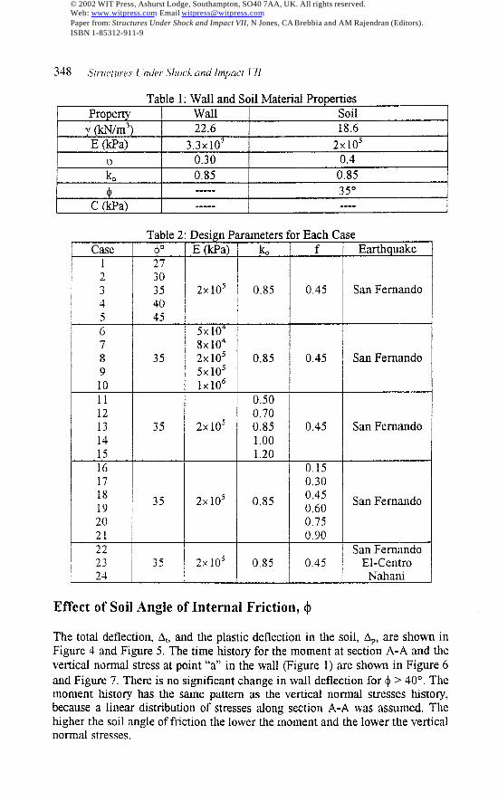
Table 1: Wall and Soil Material PropertiesProperty wall Soil
y (kN/m3) 22.6 18.6E (kPa) 3.3X10⁷ 2X10⁵
0.30 0,4
: 0,85 0.85+ ..--- 35°
C (kPa) ----. -.—
F
789
l--+!-121314
r151617181920
H-
Table 2: Design Parameters0 /E(kPa)l k
273035 I 2x 10⁵I 0.85
*
+
0.7035 2X10⁵ 0.85
1.001.20
35 I 2x 10⁵ I 0.85
351
2X1051
0.85
r Each Cf
0.45
0.45
0.45
0.150.300.450,600,750,90
0.45
;e
7Earth uake
San Fernando
San Fernando
San Fernando
San Fernando
--lSan FernandoE1-Centro
Nahani
Effect of Soil Angle of Internal Friction, $
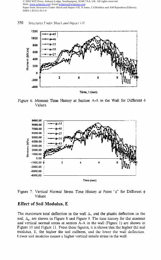
The total deflection, At, and the plastic deflection in the soil, AP,are shown inFigure 4 and Figure 5, The time history for the moment at section A-A and thevertical normal stress at point “a” in the wall (Figure 1) are shown in Figure 6and Figure 7. There is no significant change in wall deflection for + >40°. Themoment history has the same pattern as the vertical normal stresses histoty,because a linear distribution of stresses along section A-A was assumed. Thehigher the soil angle of friction the lower the moment and the lower the verticalnormal stresses,
© 2002 WIT Press, Ashurst Lodge, Southampton, SO40 7AA, UK. All rights reserved.Web: www.witpress.com Email [email protected] from: Structures Under Shock and Impact VII, N Jones, CA Brebbia and AM Rajendran (Editors).ISBN 1-85312-911-9
Structures ( ‘t~der.$hoek and Impact 1’11 349
0,25
0,2
O.t 5
~ 0.1
;~ 0.05:~ o
g -0.05
-&i
-0.1 s
4.2
Time (sw.)
Figure 3: Displacement Time Histoxy For the Three Earthquake Records.
.0.25 -0.1 .#, ts .0, ! .O. #5 0
0.0.,11.” Im}
Figure 4: Total Deflection for Different+ Values.
----==\\‘\
‘k, 4,5- . .
I-+.3s -+.30
— +=40 - +.45 ,
----=...
-+-27 I1.0
0.50
d
.0.100 .0,050 0,000
Pfast(c oefhctlon (m)
Figure 5: Plastic Deflection for Different $ Values.
© 2002 WIT Press, Ashurst Lodge, Southampton, SO40 7AA, UK. All rights reserved.Web: www.witpress.com Email [email protected] from: Structures Under Shock and Impact VII, N Jones, CA Brebbia and AM Rajendran (Editors).ISBN 1-85312-911-9
3.50 .S[rticrzovs[ kder Shock and impact 111
1200
1000
800
F~ 600x; 400
?’ 200:
0
-200
400 t ,
Time, t (see)
Figure 6: Moment Time History at Section A-A in the Wall for DiiYerent +Values.
9000.008000.007000.006000.005000.00
zn 4000.00x; 3000.00; 2000.00$J 1000.00E 0.00
-1000.00-2000.004000.00-4000.00
Time (see)
Figure 7: Venicai Normal Stress Time History at Point “a” for Different $Values.
Effect of Soil Modulus, E
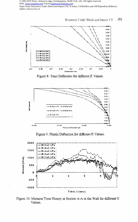
The maximum total deflection in the wall At, and the plastic deflection in the
soil, AP,are shown in Figure 8 and Figure 9. The time history for the momentand vertical normal stress at section A-A in the wall (Figure 1) are shown inFigure 10 and Figure 11, From these figures, it is shown that the higher the soilmodulus, E, the higher the soil stifFness, and the lower the wall deflection.Lower soil modulus causes a higher vertical tensile stress in the wall.
© 2002 WIT Press, Ashurst Lodge, Southampton, SO40 7AA, UK. All rights reserved.Web: www.witpress.com Email [email protected] from: Structures Under Shock and Impact VII, N Jones, CA Brebbia and AM Rajendran (Editors).ISBN 1-85312-911-9
‘\.\
\gg \:
El—C =5.4 kP*-~=1#4 kPa—-- .2.$ !iPm
-6.5s5 kPa-n= f.@ kPa
.4.4 .a.3s .4.1 .9.25 .8,2 .8.%5 .O, i .a, os 0
O* II* CII.” {m)
Figure 8: Total Deflection for different E Values.
~
!,00
0,60
.0.180 .0,400 .0.0s0 0,000
PI., tl, O.n, ct(. ” (m)
Figure 9: Plastic Deflection for dtierent E Values.
2000
1500
z 1000~
~ 500
E
~ o
-500
-1000 L————._———..—. . .. —. ——— .. ..- —-.-..-. -———-———
Time, t (see)
351
1
0
Figure 10: Moment Time History at Section A-A in the Wall for different EValues,
© 2002 WIT Press, Ashurst Lodge, Southampton, SO40 7AA, UK. All rights reserved.Web: www.witpress.com Email [email protected] from: Structures Under Shock and Impact VII, N Jones, CA Brebbia and AM Rajendran (Editors).ISBN 1-85312-911-9
K__!—s .$.4 I(P,
—5 =1.4 mPa ,/’-\—@=2a5 kPa
-.-6 =3.5 I(P, A-_ 4, .,,
)
TIlm. (s.. )
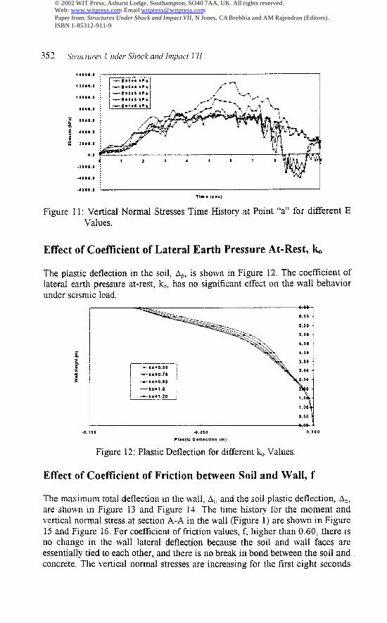
Figure 11: Vertical Normal Stresses Time History at Point “a” for different EValues.
Effect of Coeftlcient of Lateral Earth Pressure At-Rest, k
The plastic deflection in the soil, AP, is shown in Figure 12. The coefficient oflateral earth pressure at-rest, ~, has no significant effect on the wall behaviorunder seismic load.
4I.1OO .0.050 0.000
Plasttc D, flectlo” [m)
Figure 12: Plastic Deflection for different L Values.
6,00
S.SO
5,00
4.50
4,00
3,50 ,
3.00 J
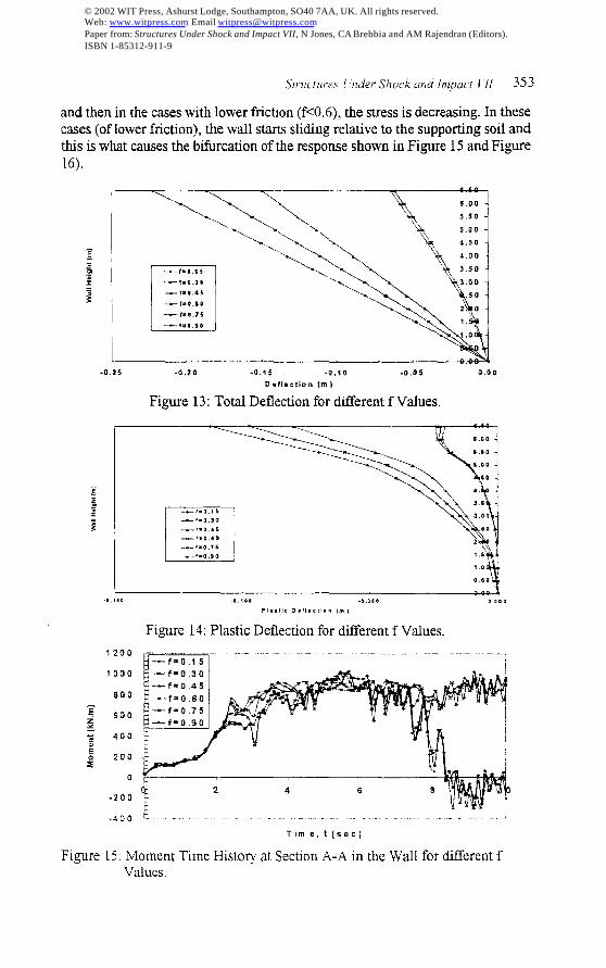
Effect of Coefilcient of Friction between Soil and Wall, f
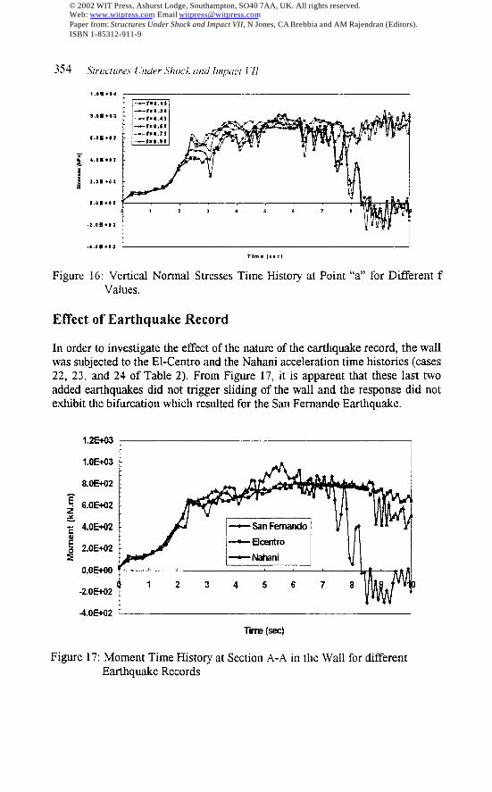
The maximum total deflection in the wall, A,, and the soil plastic deflection, AP,are shown in Figure 13 and Figure 14. The time history for the moment andvertical normal stress at section A-A in the wall (Figure 1) are shown in Figure15 and Figure 16. For coefficient of friction values, f, higher than 0.60, there isno change in the w,all lateral deflection because the soil and wall faces areessentially tied to each other, and there is no break in bond between the soil andconcrete. The vertical normal stresses are increasing for the first eight seconds
© 2002 WIT Press, Ashurst Lodge, Southampton, SO40 7AA, UK. All rights reserved.Web: www.witpress.com Email [email protected] from: Structures Under Shock and Impact VII, N Jones, CA Brebbia and AM Rajendran (Editors).ISBN 1-85312-911-9
.Strucrwes [ ‘kder Skock und [tnpact 1’11 353
and then in the cases with lower friction (f<O.6), the stress is decreasing. In thesecases (of lower friction), the wall starts sliding relative to the supporting soil andthis is what causes the bifurcation of the response shown in Figure 15 and Figure
TT-r, a,l$
—!. 0.30
—f= $.45
-f. o,se
kM_J-0,25 -0.20 -0. ts -0. <0 .0.05 0,00
De floctic.. (m)
Figure 13: Total Deflection for diiTerent f Values.
I
I ~~
El—r. o,t6 -..—--f. o 30—,.0.46
—,.0.60
—(.0 76
—f. o,so
.4., s0 .0 ,0, .0 ,880 , ,*O
?l, ,!,, D, fl,’t l.” (m,
Figure 14: Plastic Deflection for different f Values.
i200
1000
800
o
-200
F===-” ““- ‘-” “- ‘-’ ‘“- 1
4 6
.4~o k.-...- . . . . . . . . .Time, t(sec]
Figure 15: Moment Time History at Section A-A in the Wall for different fValues.
© 2002 WIT Press, Ashurst Lodge, Southampton, SO40 7AA, UK. All rights reserved.Web: www.witpress.com Email [email protected] from: Structures Under Shock and Impact VII, N Jones, CA Brebbia and AM Rajendran (Editors).ISBN 1-85312-911-9
354 .Ytrzlcrzlres l’nder Shock and impact 171
C.@m*o>
o,8m.l@
.2. OB. B1
.4,0 m.o J I I
Tint, Isa=)
Figure 16: Vertical Normal Stresses Time History at Point “a” for Different fValues.
Effect of Earthquake Record
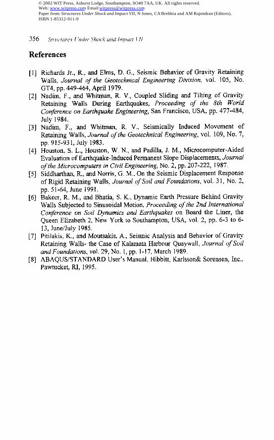
In order to investigate the effect of the nature of the earthquake record, the wallwas subjected to the E1-Centro and the Nahani acceleration time histories (cases22, 23, and 24 of Table 2). From Figure 17, it is apparent that these last twoadded earthquakes did not trigger sliding of the wall and the response did notexhibit the bifurcation which resulted for the San Fernando Earthquake.
1.25031
1.0E+03
8.0E@2
O.OEI’00
-2.0E+02
4.0502 t I
-rim (Se@
Figure 17: Moment Time History at Section A-A in the Wall for differentEarthquake Records
© 2002 WIT Press, Ashurst Lodge, Southampton, SO40 7AA, UK. All rights reserved.Web: www.witpress.com Email [email protected] from: Structures Under Shock and Impact VII, N Jones, CA Brebbia and AM Rajendran (Editors).ISBN 1-85312-911-9

Structures [ “t~derShock am’ lmpacr f ’11 355
Conclusions
A parametric study has been conducted to study the effect of the following soilproperties: soil angle of internal friction, soil modulus, coelllcient of lateral atrest pressure, coefficient of friction between soil and wall, and type ofearthquake record on the seismic total and plastic deflection of cantileverretaining walls. The time histories of the moment and the vertical normalstresses in the wall have been determined. From this study, the following can beconcluded.1.
2,
3.
4.
5,
6.
7,
Among all design parameters used in this study, the soil modulus ofelasticity, E,, is the most effective parameter controlling the total deflectionof the wall. The total deflection of the wall was decreased from 39.3 cm toabout 9,6 cm by an increase of the soil modulus from 5x 10q kPa to 1x10⁶kPa. The reduction in deflection was about 75V0. So, all possible effortsshould be made to increase the soil modulus in the retaining wall backfdl,by good compaction or stabilization, e.g.The pl,astic deflection is the most important parameter controlling thebehavior of retaining walls during earthquake. The soil angle of internalfriction, +, is the most significant prmameter controlling the final values ofpermanent deflection. Increasing the soil angle of internal friction from 27°to 45°, reduced the plastic deflection from 10.5 cm to be 0.4 cm: a reductionof about 96’%o.In general, angle of internal friction increases dramaticallywith increasing baclcfdl density,The lower the soil-angle of internal friction the lower the soil stiffness. As aresult, excessive deflection and higher permanent deflection should beexpected.The coefficient of lateral earth pressure at-rest had almost no effect on the
behavior of the cantilever retaining wall,The coefficient of lateral earth pressure at-rest had no effect on key momentand normal stresses in the watl.The coefficient of friction between wall and soil had sigtilcant effect onthe wall deflection and soil permanent displacement, especially for smoothwall surfaces. Increasing the coefficient of friction from 0.15 to 0.45reduced the total deflection from 22.3 cm to 15 cm, a reduction of 33.0!40,and the plastic deflection from 11.3 cm to 8 cm, a reduction percentage of30.0’?4..But an increase of the coefficient of friction from 0.60 to 0.90reduced the total deflection from 6.40 cm to 6.17 cm (a reduction of only4,0Yo), and the plastic deflection from 2,40 cm to 2.06 cm (a reduction of14.OYO).For wall-to-soil friction, a coefficient below 0.45, and the San Fernandoexcitation, the wail slides on the supporting soil. As a result, the response isquite different from the response with larger frictional coefficients thatapparently tie the watl to the supporting soil. Although this sliding wasobsemed only in the San Fernando earthquake, it indicates that a roughinterface is desirable.
© 2002 WIT Press, Ashurst Lodge, Southampton, SO40 7AA, UK. All rights reserved.Web: www.witpress.com Email [email protected] from: Structures Under Shock and Impact VII, N Jones, CA Brebbia and AM Rajendran (Editors).ISBN 1-85312-911-9
356 .’[rz{ctltre.r( ‘riderShock and [Inpuci I“[I
References
[1] Mchwds Jr., R., mdEks, D. G., Seismic Behavior of Gravi~RetatitigWalls, Journal of the Geotechnical Engineering Division, vol. 105, No.GT4, pp. 449-464, April 1979.
[2] Nadim, F., and Whitrmq R. V., Coupled Sliding and Tilting of GravityRetaining Walls During Earthquakes, Proceeding of the 8th worldConference on Earthquake Engineering, San Francisco,USA, pp. 477-484,July 1984.
[3] Nadim, F., and Whitman, R. V,, Seismically Induced Movement ofRetaining Walls, Journal of the Geotechnical Engineering, vol. 109, No. 7,Pp. 915-931, Ju1y 1983.
[4] Houston, S. L., Houston, W. N., and Padilla, J. M., Microcomputer-AidedEvaluation of Earthquake-Induced Permanent Slope Displacements, Journalof the Microcomputers in Civil Engineering, No. 2, pp. 207-222, 1987.
[5] Siddharthan, R., and Norns, G. M., On the Seismic Displacement Responseof Rigid Retaining Walls, Journal of Soil and Foundations, vol. 31, No. 2,pp. 51-64, June 1991.
[6] Bakeer, R. M., and Bhati% S. K., Dynamic Earth Pressure Behind GravityWalls Subjected to Sinusoidal Motion, Proceeding of the .2nd InternationalConference on Soil Dynamics and Earthquakes on Board the Liner, theQueen Elizabeth 2, New York to Southampton, USA, vol. 2, pp. 6-3 to 6-13, June/July 1985.
[7] Pitilakis, K., and Moutsakis, A., Seismic Analysis and Behavior of GravityRetaining Walls- the Case of Kalamata Harbour QuayWall, .lournal of Soiland Foundations, vol. 29, No. 1, pp. 1-17, March 1989.
[8] ABAQUS/STANDARD User’s Manual, Hibbitt, Karlsson& Sorensen, Inc.,Pawtucket, RI, 1995.
© 2002 WIT Press, Ashurst Lodge, Southampton, SO40 7AA, UK. All rights reserved.Web: www.witpress.com Email [email protected] from: Structures Under Shock and Impact VII, N Jones, CA Brebbia and AM Rajendran (Editors).ISBN 1-85312-911-9