Embed Size (px)
Citation preview

Development of Compressible-Incompressible Link to Efficiently Model Bubble Dynamics near Floating Body
Chao-Tsung Hsiao1, Georges L. Chahine2 1 DYNAFLOW, INC. 10621-J Iron Bridge Road, Jessup, MD 20794, USA, [email protected]
2 DYNAFLOW, INC. 10621-J Iron Bridge Road, Jessup, MD 20794, USA, [email protected]
Keywords: Fluid Structure Interaction, boundary element method, bubble dynamics, free surface, piercing body
Abstract. The interaction between an explosion bubble and a floating body involves several physical phenomena
that an accurate numerical simulation needs to capture. These include proper description of the initial shock wave
and its propagation and interaction with the floating body and free surface and the subsequent growth, dynamics,
collapse, and interaction of the resulting bubble with the structure. A numerical procedure which links a
compressible finite difference flow solver with an incompressible boundary element method was applied to
capture both shock and bubble phases efficiently and accurately. Both codes solved the fluid dynamics problem
and coupled with a finite element structure code to simulate fluid-structure interaction. This numerical approach
was validated by comparing the numerical results with available experimental measurements. The effects of
including or neglecting some modeling aspects on the solution were considered.
Introduction
Underwater explosion interaction with a structure has long been an area of interest in the fluid and structures
community [1-2]. The complex dynamics results from a shock wave created by the explosion, which leaves
behind it a very dynamic underwater bubble. The shock wave and the bubble strongly interact with the structure.
The dynamics of the bubble result in long duration loads with time scales, which could match the structure natural
frequency. Modeling of the initial times in the dynamics requires a compressible flow solver to capture shock
wave emission and propagation. However, such a flow solver usually uses a finite difference method (FDM)
which requires very fine spatial resolution and small time step sizes. This makes them not very efficient for
resolving the relatively long duration bubble dynamics. To overcome this, an incompressible potential flow solver
based on a boundary element method (BEM) can be used to model the bubble dynamics once the shock phase has
been described properly.
In this study we present the numerical procedures to transfer from the FDM compressible flow solver the flow
field variables required to proceed with the BEM incompressible potential flow computations. In addition we
describe coupling procedures between the BEM and a finite element method (FEM) based structure code, which
are used to enable simulation of the full fluid-structure interaction between the bubble and the floating body.
Unlike for a fully submerged body, a floating object pierces the free surface and only the wetted area of the body
and the water free surface need to be discretized and solved for the BEM code. Since the body waterline changes
dynamically, meshing, re-meshing and interpolation between BEM and FEM meshes needs to be done at each
communication step for proper information exchange between the fluid and the structure codes. In this study we
compare the numerical results with experimental measurements to validate the developed numerical procedure
and the importance of various parameters which influence the accuracy of numerical simulations is addressed by
isolating their effects.
Flow Stage Fluid Code Interface Structure Code
Tim
e
Shock Phase GEMINI
Co
up
ler
Inte
rfa
ce
DYNA3D
Compressible-Incompressible Link (Handoff)
Bubble Phase 3DYNAFS-BEM®
Incompressible-Compressible Link(Handback)
Rebound Phase GEMINI
Figure 1. Schematic diagram of the numerical approach used to simulate fluid structure interaction problem
between an underwater explosion and a structure.
Numerical Approach
Overview of the Approach. In the present study a hybrid scheme using three solvers was utilized to simulate the
Fluid Structure Interaction (FSI) problem between an underwater explosion bubble and a floating body. This
hybrid scheme combines the advantages of a compressible code, GEMINI [3], and an incompressible solver,

3DYNAFS-BEM© [4], to capture the shock and bubble phases. Both GEMINI and 3DYNAFS-BEM
© are coupled with
the structure dynamics code, DYNA3D [5], through an interface coupler. The schematic diagram shown in Figure
1 illustrates the hybrid numerical approach used in this paper. As illustrated in Figure 1, after the shock phase the
flow field is “handed off” from GEMINI to 3DYNAFS-BEM©
[6], which is then used to simulate most of the bubble
period until the end of the bubble collapse where due to high speeds or to reentrant jet impact compressible flow
effects prevail again. To continue the simulation into the rebound phase the solution is “handed back” [7] to
GEMINI. In the current study, we will only focus on the shock and bubble phase during the bubble first period.
FDM-Based Compressible Flow Solver. GEMINI is a multi-component compressible Euler equation solver
developed by the Naval Surface Warfare Center, Indian Head division based on a finite difference scheme [3].
The code solves continuity and momentum equations for a compressible inviscid liquid in Cartesian coordinates.
These can be written in the following format:
Q E F G
St x y z
, (1)
2
2
2
0
0
, , , , 0 ,
t t t t
u v wvuu u p wu
Q v E uv F v p G wv S
w uw vw gw pe gwe p u e p v e p w
(2)
where is the liquid density, p is the pressure, u, v, and w are the velocity components in the x, y, z directions
respectively (z is vertical), g is the acceleration of gravity , and et=e+0.5(u2+v
2+w
2) is the total energy with e
being the internal energy. Eq (1) is applied to solve gas, liquid, or other media with an equation of state relating
pressure, density, and energy for a given material or phase.
GEMINI uses a high order Gudonov scheme. It employs the Riemann problem to construct a local flow
solution between adjacent cells. The numerical method is based on single material higher order MUSCL scheme
and tracks each material. To improve efficiency, an approximate Riemann problem solution replaces the full
problem. The MUSCL scheme is augmented with a Lagrange re-map treatment of mixed cells. The code has been
extensively validated against experiments [3].
BEM-Based Incompressible Flow Solver. 3DYNAFS-BEM© is a potential flow solver based on a boundary
element method. The code solves the Laplace equation, 2 0 , for the velocity potential, , with the velocity
vector defined as u . A boundary integral method is used to solve the Laplace equation based on Green’s
theorem:
2 2 .S
G G d G G dS
n (3)
In this expression is the domain of integration having elementary volume d. The boundary surface of is S,
which includes the surfaces of the bubble and the nearby boundaries with elementary surface element dS. n is the
local normal unit vector. 1/G x y is Green's function, where x is a fixed point in and y is a point on the
boundary surface S. Eq (3) reduces to Green’s formula with being the solid angle under which x sees the
domain, :
(x) (y) (x,y) (x,y) (y) ,S
Ga G dS
n n
(4)
where a is the solid angle. To solve eq (4) numerically, the boundary element method, which discretizes the
surface of all objects in the computational domain into panel elements, is applied.
Eq (4) provides a relationship between and /n at the boundary surface S. Thus, if either of these two
variables (e.g. ) is known everywhere on the surface, the other variable (e.g. /n) can be obtained. For the
current problem, at each time step on the bubble and free surface will be obtained through the integration of
Bernoulli equation:
21 1,
2l
dp p gz
dt
(5)
where pl is the liquid pressure at the bubble surface or free surface. For the floating body surface, /n is
provided when the code is coupled with a structure code. The velocity potential, , and /n derived from eq
(5) on the bubble and free surfaces are used to compute the velocity vector, u. The locations of the bubble and
free surfaces nodes are then updated with the coordinates of surface nodes, x, advanced according to /d dt x u .
FEM-Based Structure Code. DYNA3D is a non-linear explicit structure dynamics code based on finite element
method developed by the Laurence Livermore National Laboratory. DYNA3D is used here to handle the floating
body motion and deformation with the loading provided by the fluid solver. DYNA3D uses a lumped mass
formulation for efficiency. This produces a diagonal mass matrix M, to express the momentum equation as: 2
ext int2,
d
dt
xM F F (6)
where Fext represents the applied external forces, and Fint the internal forces. The acceleration, 2 /d dta x , for
each element is obtained through an explicit temporal central difference method. Additional details on the general
formulation can be found in [5].
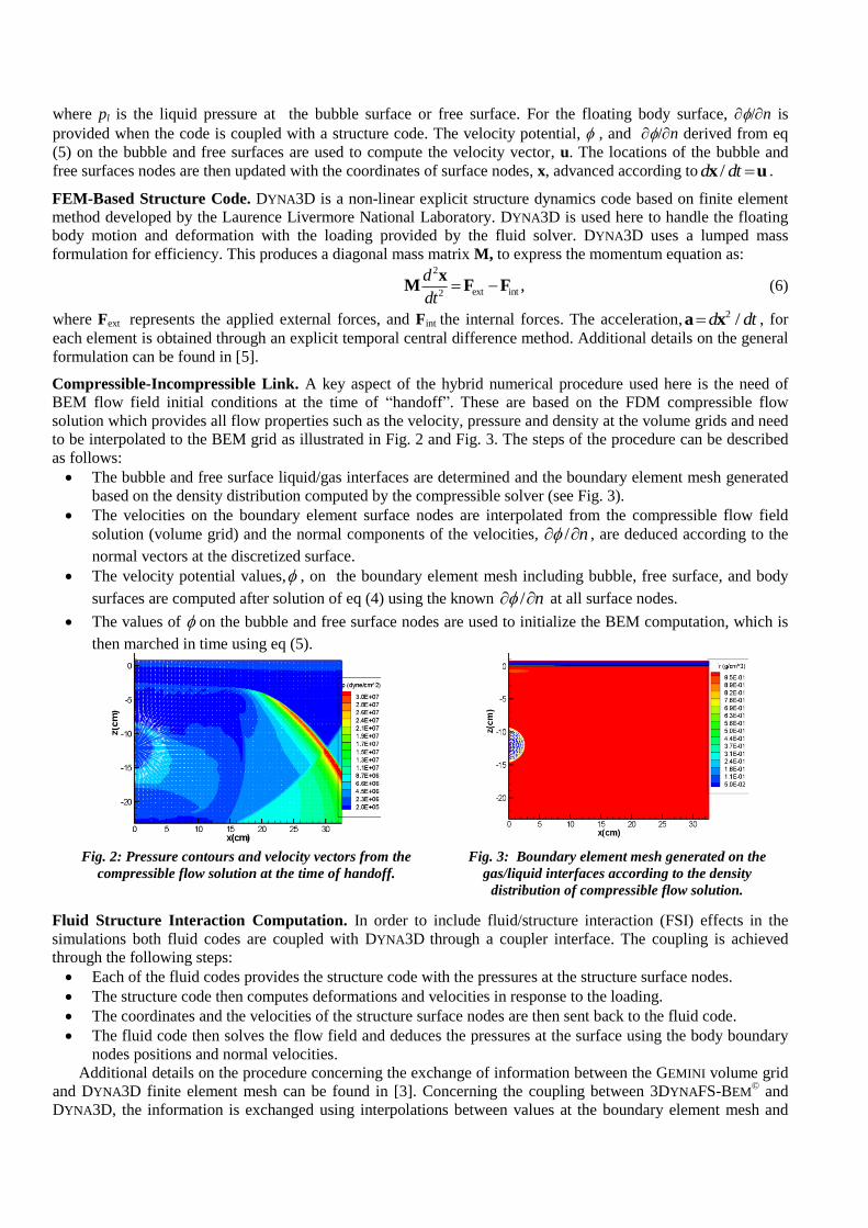
Compressible-Incompressible Link. A key aspect of the hybrid numerical procedure used here is the need of
BEM flow field initial conditions at the time of “handoff”. These are based on the FDM compressible flow
solution which provides all flow properties such as the velocity, pressure and density at the volume grids and need
to be interpolated to the BEM grid as illustrated in Fig. 2 and Fig. 3. The steps of the procedure can be described
as follows:
The bubble and free surface liquid/gas interfaces are determined and the boundary element mesh generated
based on the density distribution computed by the compressible solver (see Fig. 3).
The velocities on the boundary element surface nodes are interpolated from the compressible flow field
solution (volume grid) and the normal components of the velocities, / n , are deduced according to the
normal vectors at the discretized surface.
The velocity potential values, , on the boundary element mesh including bubble, free surface, and body
surfaces are computed after solution of eq (4) using the known / n at all surface nodes.
The values of on the bubble and free surface nodes are used to initialize the BEM computation, which is
then marched in time using eq (5).
Fig. 2: Pressure contours and velocity vectors from the
compressible flow solution at the time of handoff.
Fig. 3: Boundary element mesh generated on the
gas/liquid interfaces according to the density
distribution of compressible flow solution.
Fluid Structure Interaction Computation. In order to include fluid/structure interaction (FSI) effects in the
simulations both fluid codes are coupled with DYNA3D through a coupler interface. The coupling is achieved
through the following steps:
Each of the fluid codes provides the structure code with the pressures at the structure surface nodes.
The structure code then computes deformations and velocities in response to the loading.
The coordinates and the velocities of the structure surface nodes are then sent back to the fluid code.
The fluid code then solves the flow field and deduces the pressures at the surface using the body boundary
nodes positions and normal velocities.
Additional details on the procedure concerning the exchange of information between the GEMINI volume grid
and DYNA3D finite element mesh can be found in [3]. Concerning the coupling between 3DYNAFS-BEM© and
DYNA3D, the information is exchanged using interpolations between values at the boundary element mesh and
values at the surface elements of the structure finite element model. Since the water contact line of the floating
body changes dynamically, an automatic re-meshing scheme is implemented to modify the boundary element
mesh on the floating body and adapt it at each time step to the position of the waterline. The following procedure
is as follows:
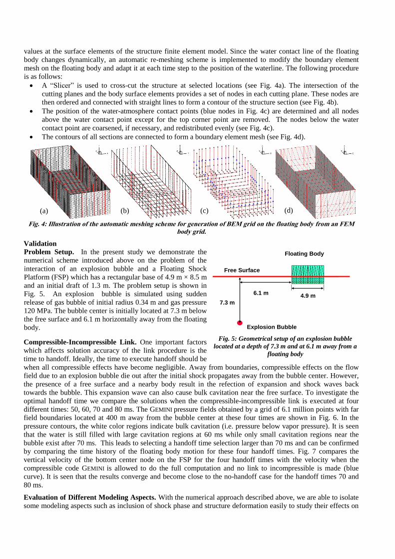
A “Slicer” is used to cross-cut the structure at selected locations (see Fig. 4a). The intersection of the
cutting planes and the body surface elements provides a set of nodes in each cutting plane. These nodes are
then ordered and connected with straight lines to form a contour of the structure section (see Fig. 4b).
The position of the water-atmosphere contact points (blue nodes in Fig. 4c) are determined and all nodes
above the water contact point except for the top corner point are removed. The nodes below the water
contact point are coarsened, if necessary, and redistributed evenly (see Fig. 4c).
The contours of all sections are connected to form a boundary element mesh (see Fig. 4d).
Fig. 4: Illustration of the automatic meshing scheme for generation of BEM grid on the floating body from an FEM
body grid.
Validation
Problem Setup. In the present study we demonstrate the
numerical scheme introduced above on the problem of the
interaction of an explosion bubble and a Floating Shock
Platform (FSP) which has a rectangular base of 4.9 m × 8.5 m
and an initial draft of 1.3 m. The problem setup is shown in
Fig. 5. An explosion bubble is simulated using sudden
release of gas bubble of initial radius 0.34 m and gas pressure
120 MPa. The bubble center is initially located at 7.3 m below
the free surface and 6.1 m horizontally away from the floating
body.
Compressible-Incompressible Link. One important factors
which affects solution accuracy of the link procedure is the
time to handoff. Ideally, the time to execute handoff should be
when all compressible effects have become negligible. Away from boundaries, compressible effects on the flow
field due to an explosion bubble die out after the initial shock propagates away from the bubble center. However,
the presence of a free surface and a nearby body result in the refection of expansion and shock waves back
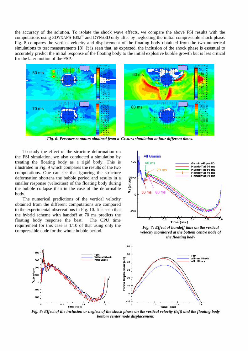
towards the bubble. This expansion wave can also cause bulk cavitation near the free surface. To investigate the
optimal handoff time we compare the solutions when the compressible-incompressible link is executed at four
different times: 50, 60, 70 and 80 ms. The GEMINI pressure fields obtained by a grid of 6.1 million points with far
field boundaries located at 400 m away from the bubble center at these four times are shown in Fig. 6. In the
pressure contours, the white color regions indicate bulk cavitation (i.e. pressure below vapor pressure). It is seen
that the water is still filled with large cavitation regions at 60 ms while only small cavitation regions near the
bubble exist after 70 ms. This leads to selecting a handoff time selection larger than 70 ms and can be confirmed
by comparing the time history of the floating body motion for these four handoff times. Fig. 7 compares the
vertical velocity of the bottom center node on the FSP for the four handoff times with the velocity when the
compressible code GEMINI is allowed to do the full computation and no link to incompressible is made (blue
curve). It is seen that the results converge and become close to the no-handoff case for the handoff times 70 and
80 ms.
Evaluation of Different Modeling Aspects. With the numerical approach described above, we are able to isolate
some modeling aspects such as inclusion of shock phase and structure deformation easily to study their effects on
(a) (b) (c) (d)
Fig. 5: Geometrical setup of an explosion bubble
located at a depth of 7.3 m and at 6.1 m away from a
floating body
7.3 m
6.1 m
Floating Body
4.9 m
Explosion Bubble
Free Surface
All Gemini
50 ms
60 ms
70 ms
80 ms
the accuracy of the solution. To isolate the shock wave effects, we compare the above FSI results with the
computations using 3DYNAFS-BEM© and DYNA3D only after by neglecting the initial compressible shock phase.
Fig. 8 compares the vertical velocity and displacement of the floating body obtained from the two numerical
simulations to test measurements [8]. It is seen that, as expected, the inclusion of the shock phase is essential to
accurately predict the initial response of the floating body to the initial explosive bubble growth but is less critical
for the later motion of the FSP.
Fig. 6: Pressure contours obtained from a GEMINI simulation at four different times.
To study the effect of the structure deformation on
the FSI simulation, we also conducted a simulation by
treating the floating body as a rigid body. This is
illustrated in Fig. 9 which compares the results of the two
computations. One can see that ignoring the structure
deformation shortens the bubble period and results in a
smaller response (velocities) of the floating body during
the bubble collapse than in the case of the deformable
body.
The numerical predictions of the vertical velocity
obtained from the different computations are compared
to the experimental observations in Fig. 10. It is seen that
the hybrid scheme with handoff at 70 ms predicts the
floating body response the best. The CPU time
requirement for this case is 1/10 of that using only the
compressible code for the whole bubble period.
Fig. 8: Effect of the inclusion or neglect of the shock phase on the vertical velocity (left) and the floating body
bottom center node displacement.
50 ms 60 ms
70 ms 80 ms
Fig. 7: Effect of handoff time on the vertical
velocity monitored at the bottom centre node of
the floating body

Fig. 9: Effect of the inclusion or neglect of the structure deformation on the bubble dynamics (left) and the floating
body bottom center node vertical velocity.
Conclusions
A hybrid numerical procedure integrating three different
solvers was developed to accurately and efficiently predict
the response of a floating body to an underwater explosion
bubble. It was found that shifting from the compressible to
the incompressible simulation (link) should be performed
after bulk cavitation has disappeared. Modeling the shock
wave and the induced bulk cavitation is important for the
simulation of the early history of the floating body response.
Inclusion of the structure deformation was also shown to
have a significant influence on the response of the floating
body during the bubble expansion and collapse phases.
Acknowledgments
This study was conducted during the execution of an SBIR
contract for the development of an alternative ship shock
testing method. The support of The Naval Surface Warfare
Center, Carderock Division (Dr. Fred Costanzo) and Indian
Head Division (Mr. Greg Harris) is gratefully acknowledged.
References
1. G.L. Chahine, and K.M. Kalumuck, “BEM Software for Free Surface Flow Simulation Including Fluid
Structure Interaction Effects,” Int. Journal of Computer Application in Technology, Vol. 3/4/5, 1998
2. K.M. Kalumuck, G.L. Chahine, G.L. and C.-T. Hsiao, “Simulation of Surface Piercing Body Coupled
Response to Underwater Bubble Dynamics Utilizing 3DYNAFS, a Three-Dimensional BEM Code,”
Computational Mechanics, 32, 319-326, 2003.
3. A.B. Wardlaw, J.A. Luton, J.R. Renzi, K.C. Kiddy, and R.M. McKeown, “The Gemini Euler Solver for the
Coupled Simulation of Underwater Explosions,” Indian Head Technical Report 2500, November 2003.
4. G.L. Chahine, R. Duraiswami, and K.M. Kalumuck, “Boundary Element Method for Calculating 2-D and
3-D Underwater Explosion Bubble Loading on Nearby Structures,” Naval Surface Warfare Center, Weapons
Research and Technology Department, Report NSWCDD/TR-93/46, September 1996.
5. DYNA3D, User manual “ A nonlinear explicit, three dimensional finite element code for solid and structural
mechanics” , January 2005.
6. C.-T. Hsiao, J-K Choi, J-K and G.L. Chahine, “Analysis of the Phenomena influencing the Accurate
Modelling of a Surface Vessel Response to an UNDEX,” 78th Shock and Vibration Symposium
Philadelphia, PA, November 4-8, 2007.
7. C.-T. Hsiao, G.L. Chahine, “Incompressible-Compressible Link to Accurately Predict Wall Pressure,” 81th
Shock and Vibration Symposium, Orlando, FL, October 24-28, 2010.
8. G.L Chahine, K.M. Kalumuck, M. Tanguay, J.P. Galambos, M. Rayleigh, R.D. Miller and C. Mairs,
“Development of a Non-Explosive Ship Shock Testing System-SBIR Phase I Final Report,” Dynaflow, Inc.
Report 2M3030-1 DTRC, March 15, 2004.
Fig. 10: Boundary element mesh generated on
the gas/liquid interfaces determined according
to the density distribution of compressible flow
solution at the handoff time.