Embed Size (px)
Citation preview

Page 1
Development of climate friendlier truck refrigeration systems with R290
in South Africa
Transport Refrigeration in South Africa
Side Event MOP Dubai 2015
Bill Wilson, Transfrig
Dr Daniel Colbourne, HEAT/GIZ
Michael Schuster, GIZ South Africa

Page 2
Contents
• The project
• Safety aspects and risk assessment
• COP improvements
• Emission savings – Life cycle comparison

Page 3
- the cooperation partner
• Only South African transport refrigeration company
• Founded in 1980
• Local production in Johannesburg
• High market share for trucks and vans in South Africa
• Sales in Sub-Saharan countries
and internationally
• leader for environmental friendly
transport refrigeration technology
in Africa

Page 4
Technical description
MT450 MT480
Refrigerant R-404a HC-290
Cooling capacity 7.95 kW for 0°C
4.55 kW for -20°C
7.95 kW for 0°C
4.55 kW for -20°C
Powered by Open-type, driven by diesel
engine
Semi-hermetic compressor,
electrically driven, diesel-driven
alternator
Expansion device Thermostatic expansion valve Electronic expansion valve
Compressor Fixed speed Variable speed (60 – 100%)
Condenser tubing 9.5 mm 5 mm
Evaporator tubing 9.5 mm 7 mm

Page 5
Circuit Arrangement of the new MT480
Condenser
Compressor
Condensing unit
Truck
EEV
Evaporator
Combined suction
Accumulator / liquid receiver
HGD valve
Non-return Valve
HP LP

Page 6
Contents
• The project
• Safety aspects and risk assessment
• COP improvements
• Emission savings – Life cycle comparison

Page 7
Safety risks using
flammable
refrigerants Flammable
concentrations
Leakages
Accumulation
Size of potential leaked amount
Sources of ignition
Components
Hot surfaces
Open flames
Improper handling
Servicing
Storage and transport
Page 8
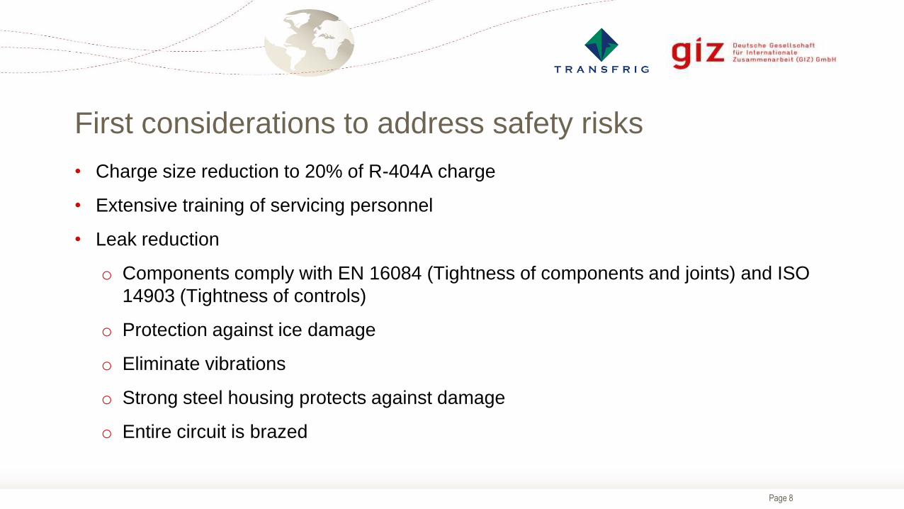
First considerations to address safety risks
• Charge size reduction to 20% of R-404A charge
• Extensive training of servicing personnel
• Leak reduction
o Components comply with EN 16084 (Tightness of components and joints) and ISO
14903 (Tightness of controls)
o Protection against ice damage
o Eliminate vibrations
o Strong steel housing protects against damage
o Entire circuit is brazed

Page 9
Leak simulation tests
Electrical panel
Truck air intake
Air intake and starter motor
Truck engine
gap
External light switch
Smoker at door
Evaporator inlet
Floor below evaporator
Beneath door
Inside, centre, high
Inside, centre, low
Test conditions (examples)
• Leak sizes
• Leak positions
• Operating conditions
• Empty/fully loaded
• Air-flow / no air-flow

Page 10
Results (example): Leak of R290 into the refrigerated space, subsequent
door opening
Evaporator fan off Evaporator fan on
Door opening
Amount of leaked gas = 1 kg (>150% of charge size 0.65kg) the in order to cover possible overcharging

Page 11
Eliminate Sources of Ignition (Example 1)
Electrical panel
• Cover
• Fully sealed against refrigerant
• Secondary barrier to the rear of the
enclosure
• Explosion proof cable glands

Page 12
Eliminate Sources of Ignition (Example 2)
Diesel engine starter motor
• Sparking contacts in casing with air
gaps positioned within the condensing
unit
pre-purge system operates condenser
fan for some times. This decreases a
possible refrigerant accumulation to
below the lower flammability limit
Page 13
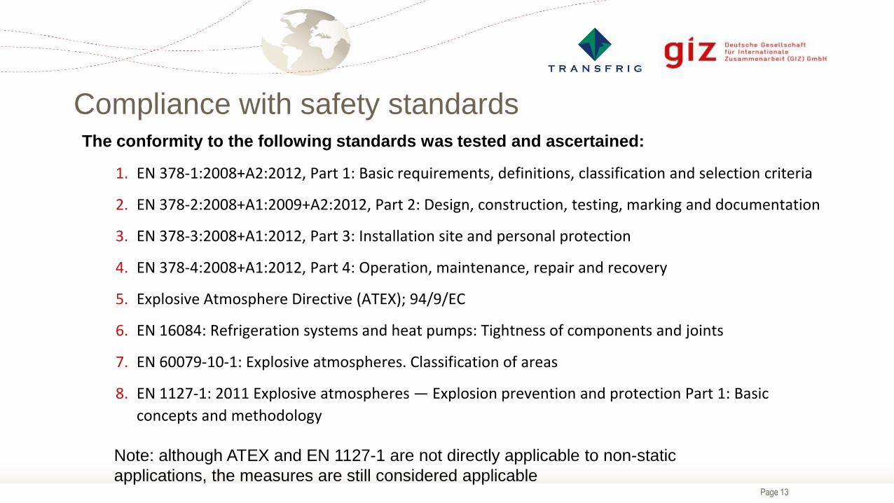
Compliance with safety standards The conformity to the following standards was tested and ascertained:
1. EN 378-1:2008+A2:2012, Part 1: Basic requirements, definitions, classification and selection criteria
2. EN 378-2:2008+A1:2009+A2:2012, Part 2: Design, construction, testing, marking and documentation
3. EN 378-3:2008+A1:2012, Part 3: Installation site and personal protection
4. EN 378-4:2008+A1:2012, Part 4: Operation, maintenance, repair and recovery
5. Explosive Atmosphere Directive (ATEX); 94/9/EC
6. EN 16084: Refrigeration systems and heat pumps: Tightness of components and joints
7. EN 60079-10-1: Explosive atmospheres. Classification of areas
8. EN 1127-1: 2011 Explosive atmospheres — Explosion prevention and protection Part 1: Basic
concepts and methodology
Note: although ATEX and EN 1127-1 are not directly applicable to non-static
applications, the measures are still considered applicable

Page 14
Leak identification system
Gas detector
• Immediate detection of leak
• Unreliable in the long-term
• Regular calibration and checking
needed
• Easily damaged
• Adds substantial costs
Automatic shut-down based on system
operating parameters
• e.g. suction pressure & temperature,
superheat, degree of EEV opening
• Longer response time than gas detector
• More reliable in the long-term, no
calibration needed
• No contamination
• Extensive testing necessary
Chosen because of low cost, better
reliability, not dependent upon special
maintenance over lifetime

Page 15
Safety concept – reduce risk of flammable refrigerant
1. Reduce charge size
2. Reduce leakages by using semi-hermetic design and tight components
3. Determine possible areas of high refrigerant concentrations after leak
4. Remove sources of ignition
5. Install automatic shut-off in case of (catastrophic) leakage
6. Train personnel in the safe use of hydrocarbon refrigerants

Page 16
Contents
• The project
• Safety aspects and risk assessment
• COP improvements
• Emission savings – Life cycle comparison

Page 17
Improvement of energy efficiency
Measure Efficiency benefits
HC-290 refrigerant
Reduced condenser tubes
Reduced evaporator tubes
Redesign of evaporator and condenser
Liquid suction heat exchanger
Electronic expansion valve
Variable speed compressor

Page 18
Performance improvements due to use of R-290 at high ambient temperatures
(fixed speed compressor)
Performance at extreme conditions for MT (T = 0°C) Performance at extreme conditions for LT (T = -20°C)
COP up to
28% higher COP up to
27% higher

Page 19
Higher cooling capacity at high ambient temperatures
Cooling capacity at extreme conditions for MT (T = 0°C) Cooling capacity at extreme conditions for LT (T = -20°C)
Higher capacity
at high ambient
temperatures
Higher capacity
at high ambient
temperatures

Page 20
Contents
• The project
• Safety aspects and risk assessment
• COP improvements
• Emission savings – Life cycle comparison

Page 21
Life cycle emissions – comparison R-404a and HC-290
R-404a unit HC-290 unit
GWP 3,922 3
Charge size 3.5 kg 0.65 kg
Annual
leakage rate
50 % <<50 %
Direct
emissions
6.9 t CO2 eq 0.001 t CO2 eq
Fuel
consumption*
1.2 L/h 1.0 L/h
Runtime hours 1,500 h/year 1,500 h/year
Indirect
emissions
4.8 t CO2 eq 4.0 t CO2 eq
Total
emissions
11.8 t CO2 eq
4.0 t CO2 eq
* estimate
0
5
10
15
R-404a HC-290
Em
issio
ns [t C
O2 e
q]
Indirect emissions Direct emissions

Page 22
Summary
Environmentally friendly refrigerant
High energy efficiency (also for high ambient temperatures)
Reduced refrigerant leakage
Comprehensive safety concept for flammable refrigerants
Compliance with safety standards