Embed Size (px)
Citation preview

Y O 45-3 /7
( IASA-Tf l -UYZ1Z) GEVELGEMENT Cf E U B I E D W I R E Nb7-12831 GAGES FOR WEASUREMENT OF WALL S H E A R STRESS IN B L A S T A N E E X P E R I M E N 2 S In ter ia h e p o r t , G c t , 158€ ( N A S A ) 38 I; CSCL 748 Unclas
G3/35 44677
DEVELOPMENT OF BURIED WIRE GAGES FOR MEASUREMENT OF WALL SHEAR STRESS IN ‘BLASTANE’ EXPERIMENTS
SREEDHARA V. MURTHY Department of Mechanical Engineering University of the Pacific, Stockton, CA.
and
FRANK W. STEINLE Chief, Aerodynamic Facilities Branch (RAF) NASA Ames Research Center, Moffett Field, CA.
prepared f o r NASA Ames Research Center under Cooperative Agreement No. NCC 2-35’1 September 1986
N A S A NATIONAL AERONAUTICS AND SPACE ADMINISTRATION AMES RESEARCH CENTER MOFFETT FIELD, CA 94035
https://ntrs.nasa.gov/search.jsp?R=19870003398 2018-07-14T18:17:02+00:00Z

BURIED WIRE GAGES FOR 'BLASTANE' EXPERIMENTS. Page i
INTERIM REPORT
DEVELOPMENT OF BURIED WIRE GAGES FOR MEASUREMENT OF W A L L SHEAR STRESS IN 'BLASTANE' EXPERIMENTS
Sreedhara V. Murthy * University of the Pacific, Stockton, CA
and
Frank W. Steinle * * NASA Ames Research Center, Moffett Field, CA
ABSTRACT
Buried Wire Gages operated from a Constant Temperature Anemometer System are among the special types of instrumentation to be used in the Boundary Layer Apparatus f o r Subsonic and Transonic flow Affected by Noise Environment ('BLASTANE'). These Gages are of a new type and need to be adapted for specific applications. Methods were developed to fabricate Gage inserts and mount those in the 'BLASTANE' Instrumentation Plugs. A large number of Gages were prepared and operated from a Constant Temperature Anemometer System to derive some of the calibration constants for application to fluid-flow wall shear-stress measurements. The final stage of the calibration was defined, but could not be accomplished because of non-availability of a suitable flow simulating apparatus. This report provides a description of the Buried Wire Gage technique, an explanation of the method evolved f o r making proper Gages, the procedure for calibrating the Gages and the results of measurements performed for determining two of the calibration constants, namely Temperature Coefficient of Resistance and Conduction Loss Factor.
* Adjunct Research Associate Professor, Department of Mechanical Engineering.
* * Chief, Aerodynamic Facilities Branch, Aerodynamics Division.

BURIED WIRE GAGES FOR 'BLASTANE' EXPERIMENTS. Page ii
DEVELOPMENT OF BURIED WIRE GAGES FOR MEASUREMENT OF WALL SHEAR STRESS IN 'BLASTANE' EXPERIMENTS
TABLE OF CONTENTS PAGE
NOMENCLATURE . . . . . . . . . . . . . . . . . . . . . . . . . . . . . . . . . . . . . . . . . iii
1, INTRODUCTION . . . . . . . . . . . . . . . . . . . . . . . . . . . . . . . . . . . . . . . . . 1
2. BURIED WIRE GAGE TECHNIQUE . . . . . . . . . . . . . . . . . . . . . . . . . . . 3
3. INSTRUMENTATION...................................... 4
3.1 Buried Wire Gages . . . . . . . . . . . . . . . . . . . . . . . . . . . . . . . 5 3.2 Anemometer System . . . . . . . . . . . . . . . . . . . . . . . . . . . . . . . 9 3.3 Environmental Testing Chamber . . . . . . . . . . . . . . . . . . . 13
4. CALIBRATION PROCEDURE ................................ 14
4.1 Resistance-Temperature Law ...................... 14 4.2 Conduction Loss Factor .......................... 14 4.3 Equivalent Length Factor ........................ 16
5. RESULTS AND DISCUSSION .............................. 18
6. CONCLUDING REMARKS . . . . . . . . . . . . . . . . . . . . . . . . . . . . . . . . . . . 19
7. ACKNOWLEDGMENTS . . . . . . . . . . . . . . . . . . . . . . . . . . . . . . . . . . . . . . 20
8. REFERENCES . . . . . . . . . . . . . . . . . . . . . . . . . . . . . . . . . . . . . . . . . . . 20
TABLE 1 Summary of Buried Wire Gage Calibrations.
LIST OF FIGURES:
Fig. 1 Fig. 2 Fig. 3 Fig. 4 Fig. 5 Fig. 6 Fig. 7' Pig. 8 Fig. 9 Fig. 10
Schematic of Buried Wire Gage Technique. Buried Wire Gage Elements in Instrument Plugs. Substrate Insert Fabrication Stages. Instrument Plug Blank with Buried Wire Gages. 16-Channel Const. Temperature Anemometer System. Anemometer Bridge and Test Signal Circuit. Calib of Overheat Reference vs Resistance Factor. Calib of Overheat Reference vs Resistance Factor. Resistance vs Temperature Calibration for Gages. Conduction Loss Factor Calibration for Gages.

I
BURIED
A
B
b
( C / H )
d
h
h r
h 0
k
k Sub
Nu
(O/H)
P
P'
P r
R
WIRE GAGES FOR 'BLASTANE' EXPERIMENTS. Page iii
NOMENCLATURE
1
Conduotion Loss Faotor.
Equivalent Length Factor
span of the sensing element. [clear length between the electrical leads].
Overheat Reference Value Cal ibra t ion Slope. [Propor t iona l i ty constant f o r the r e l a t ionsh ip between the Overheat Reference value and the Resistance Factor f o r the Anemometer System].
Length of t h e sensing element in f l o w d i r e c t i o n . [diameter f o r wire element placed cross t o f low].
Measured t o t a l heat t r a n s f e r rate with the Gage sensing element exposed t o f low.
Calculated oonduction heat t r a n s f e r rate from the Gage sensing element t o the substrate material. [wi th the sensing element at operating temperature as set by t h e operating r e s i s t ance , and the substrate at the local f l o w recovery temperature]
Measured t o t a l heat transfer rate wi th Gage sensor plaoed i n a no-flow condi t ion [during c a l i b r a t i o n ] .
Thermal conduct ivi ty of t h e flow medium at ' w a l l ' condi t ions 1 i . e . a t sensor operating temperature]
Thermal conduct ivi ty of the substrate evaluated a t appropriate substrate temperature. [ ' reoovery ' temperature when plaoed i n f l o v , or the substrate/ambient temperature f o r c a l i b r a t i o n i n the absence of f low].
Nusselt N u m b e r f o r the flow-related heat t r a n s f e r wi th Gage sensor a t the operating r e s i s t ance .
Overheat Reference value obtained from the Overheat Reference funct ion of t h e Anemometer System.
Static Pressure a t t h e Gage loca t ion in Flow.
Static Pressure Gradient i n streamwise d i r ec t ion a t the Gage loca t ion i n f l o w . [ - (dp/dx)l .
Moleoular Prandtl Number of the flow medium at ' w a l l ' oondit ions.
= Resistance of the cable connecting the Gage - ca sensing element t o the Anemometer Sysiem .

BURIED WIRE GAGES FOR 'BLASTANE' EXPERIMENTS. ,
Page i v
LIST OF SYMBOLS (Continued)
R - Resis tance of the Gag8 sensing element.
R = Resis tance [a t l o c a l ' r e C O V 8 F Y ' condi t ions] of the r Gage sensing element w i t h the Anemometer System i n
'STANDBY' mode, and w i t h flow passing over the Gage.
R = Operating r e s i s t a n c e of the Gage sens ing element. 6 [set on the Anemometer System].
R = 'S tandard ' Resis tance va lue f o r the Gage senso r , s t d a t the re ference temperature [usua l ly 20 deg.Cl.
R = 'Cold' [at ambient condi t ions] r e s i s t a n c e of the 0 Gage sensing element f o r c a l i b r a t i o n measurements.
R = R , R , R , R = Anemometer Bridge Resis tance Values. i 1 2 3 4 [ f o r the four arms of the bridge].
(R/F) = Resis tance F a c t o r related t o the opera te r e s i s t a n c e s e t t i n g and the a c t u a l sensor r e s i s t a n c e , f o r the Overheat Reference func t ion of the Anemometer.
T = Temperature
T = Temperature of the s u b s t r a t e f o r c a l i b r a t i o n 0 measurements. [ambient tempeaturel .
T = Local ' recovery ' temperature of the w a l l flow. r [equal t o the temperature a t t a i n e d by t h e sens ing
element when it remains unheated by the anemometer system. T h i s is deduced from the measured Gage sens ing element r e s i s t a n c e value i n f low].
T = Operating temperature of the Gage sensing element.
T = Reference temperature (20 deg.Law) f o r spec i fy ing
6
s td the Gage Resistance-Temperature law.
[deduced from the opera t ing r e s i s t a n c e s e t t i n g ] .
V = Voltage suppl ied t o the bridge c i r c u i t by the
V = Voltage suppl ied t o the bridge c i r c u i t by the
anemometer system w i t h flow passing over the Gage.
anemometer system without any flow on t h e Gage. 0
X = Distance vector i n streamwise d i r e c t i o n .
OCI = Temperature Coeff ic ien t of Resis tance.
= Coef f i c i en t of abso lu t e v i s c o s i t y f o r f l o w medium.
=
y. Y Density of flow medium a t w a l l condi t ions
r = Wall Shear Stress i n f l u i d flow. W

BURIED WIRE GAGES FOR 'BLASTANE' EXPERIMENTS. Page 1
1. INTRODUCTION
Detailed measurements of f l u i d flows have been the major basis f o r suooessful development of advanced design and ana lys i s methods per ta in ing t o f l i g h t veh ic l e flow f ie lds and other p r a o t i o a l f l u i d f l o w s i t u a t i o n s . Different a spec t s of flow phenomena o a l l f o r d i f f e r e n t sets of detailed measurements, perhaps using different flow measurement techniques. Among the many facets of f l u i d flow, boundary l a y e r t r a n s i t i o n , e spec ia l ly i n high speed f l o w s , has been a subject of i n t ens ive study f o r a long time now; b u t , more detailed measurements are needed t o obtain an adequate understanding tha t can lead t o reliable predic t ion methods [ R e f . 11. Special apparatus such as the Boundary Layer Apparatus f o r Subsonic and Transonic flows Affected by Noise Environment ['BLASTANE'] have been developed t o generate a va r i ab le flow environment s u i t e d t o detailed s t u d i e s on the effects of the many f a c t o r s t h a t inf luence the t r a n s i t i o n phenomena [ R e f . 21. However, e x i s t i n g conventional f l o w instrumentat ion oannot provide the desired spectrum of detailed measurements of t r a n s i t i o n region. A new technique is needed t o non-intrusively measure w a l l flow p rope r t i e s . suoh as w a l l shear stress. One very promising technique is the Buried Wire Gage technique which uses the heated element concept for providing a measure of wall shear stress [Ref. 31.
The heated element oonoept was conceived seve ra l decades ago; b u t , app l i ca t ion of that conoept i n p r a c t i c a l flow s i t u a t i o n s remained a formidable problem f o r a long time because of the lack of a proper sensor t ha t could provide an adequate l e v e l of s e n s i t i v i t y . Typically, the heated element ooncept c o n s i s t s of a sensing element t h a t is arranged f l u s h t o the w a l l sur face i n a f l o w . The element is heated t o an appropr ia te temperature s o that the characteristios of heat t r a n s f e r r e d t o the w a l l l ayer of f l o w may be measured. In r e a l i t y , t h e measured heat t r a n s f e r rate is the t o t a l heat t r a n s f e r r e d from the heated element and t h i s has a c e r t a i n proportion accountable t o the heat l o s t by thermal conduction t o t h e substrate mater ia l surrounding t h e heated element. T h i s proportion could be rather large f o r most choioes of conventional substrate materials such as Pyrex, quar tz , p l ex ig l a s s , etc, which have been used f o r the ' h o t f i l m ' type of sensing elements. Another aspect of the heated element concept that relies heavily on the characteristics of the sensor is t h e streamwise exten t of the sensing element i n t he flow. P a r t of the measured t o t a l heat t r a n s f e r c o n s i s t s of the effects of l o c a l pressure g rad ien t s i n the f l o w . These effects must be properly accounted f o r before the component of measured heat transfer related s o l e l y t o the w a l l f l o w may be ex t r ac t ed and converted t o w a l l shear-stress. The pressure grad ien t component is d i r e c t l y proport ional t o the streamwise exten t of the sensing element and the re fo re may be reduced only by making the sensing element appreciably s l ende r .
BURIED WIRE GAGES FOR 'BLASTANE' EXPERIMENTS. Page 2
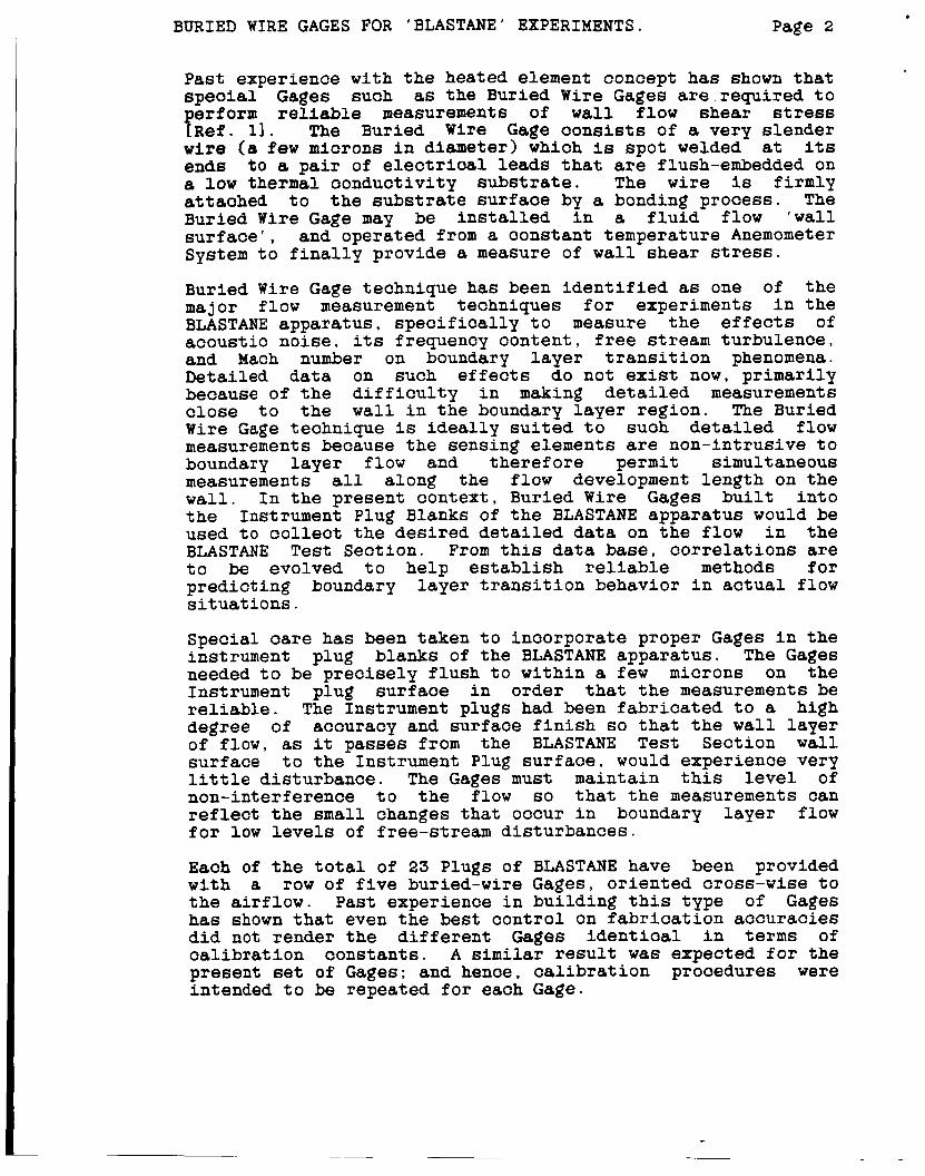
P a s t experience w i t h t he heated element concept has shown tha t s p e c i a l Gages such as the Buried Wire Gages are requi red t o erform reliable measurements of w a l l flow shear stress P R e f . 1 1 . The Buried Wire Gage c o n s i s t s of a very s lender wire ( 8 f e w microns in diameter) which is spot welded its ends t o a p a i r of electrical leads t h a t are flush-embedded on a low thermal conduct iv i ty substrate. The wire is f i rmly attached t o the substrate sur faoe by a bonding process . The Buried Wire Gage may be i n s t a l l e d i n a f l u i d flow ' w a l l s u r f a c e ' , and operated from a cons tan t temperature Anemometer System t o f i n a l l y provide a measure of w a l l shear s t r e s s .
Buried Wire Gage technique has been i d e n t i f i e d as one of the major flow measurement techniques f o r experiments i n the BLASTANE appara tus , s p e c i f i c a l l y t o measure t h e effects of acous t ic no ise , i ts frequency content , free stream turbulence , and Mach number on boundary l a y e r t r a n s i t i o n phenomena. Detai led data on such effects do not e x i s t now, pr imar i ly because of the d i f f i c u l t y i n making detailed measurements c l o s e t o the wall i n the boundary l a y e r reg ion . The Buried Wire Gage technique is i d e a l l y s u i t e d t o such detailed flow measurements because the sensing elements are non-intrusive t o boundary l aye r flow and the re fo re permit simultaneous measurements a l l along the flow development length on the wa l l . I n the present contex t , Buried Wire Gages b u i l t i n t o the Instrument Plug Blanks of the BLASTANE appara tus would be used t o c o l l e c t the desired detailed data on the flow i n the BLASTANE T e s t Sec t ion . From t h i s data base, c o r r e l a t i o n s are t o be evolved t o he lp establish reliable methods f o r pred ic t ing boundary l aye r t r a n s i t i o n behavior i n a c t u a l flow s i t u a t i o n s .
a t
Special care has been taken t o incorpora te proper Gages i n the instrument plug blanks of t he BLASTANE appara tus . The Gages needed t o be p rec i se ly f l u s h t o wi th in a f e w microns on the Instrument plug su r face i n order that t h e measurements be reliable. The Instrument plugs had been fabricated t o a high degree of accuracy and sur face f i n i s h s o t ha t the w a l l l aye r of f l o w , as it passes from the BLASTANE T e s t Sec t ion w a l l sur face t o the Instrument Plug su r face , would experience very l i t t l e d i s turbance . The Gages must maintain t h i s l e v e l of non-interference t o the flow s o t h a t the measurements can r e f l e c t t h e small changes t h a t occur i n boundary l aye r flow f o r low levels of free-stream dis turbances .
Each of t he t o t a l of 23 Plugs of BLASTANE have been provided w i t h a row of f i v e buried-wire Gages, o r i en ted cross-wise t o the a i r f l o w . P a s t experience i n bui ld ing t h i s type of Gages has shown tha t even the best con t ro l on f a b r i c a t i o n accurac ies did not render the d i f f e r e n t Gages i d e n t i c a l i n terms of c a l i b r a t i o n cons tan ts . A similar r e s u l t w a s expected for the present se t of Gages; and hence, c a l i b r a t i o n procedures were intended t o be repeated f o r each Gage.

BURIED WIRE GAGES FOR 'BLASTANE' EXPERIMENTS. Page 3
The present repor t describes the d i f f e r e n t a spec t s associated w i t h development of t h e Buried Wire Gages. The speoi f io aspeots are: p r i n c i p l e of the Buried Wire Gage technique, the Instrumentation used i n performing the c a l i b r a t i o n experiments, the three s t e p c a l i b r a t i o n procedure fo r determining the complete c a l i b r a t i o n data of the Gages, and the r e s u l t s of oa l ib ra t ion measurements.
2 . BURIED WIRE GAGE TECHNIQUE
The Buried Wire Gage technique of measuring wall shear stress i n f l u i d f l o w is based on t h e similarities tha t e x i s t between the meohanisms of momentum t r a n s f e r and heat t r a n s f e r [see Fig . 11. I n a f l u i d f l o w past a s o l i d w a l l su r f ace , the flow l a y e r next t o t he w a l l surface is heavi ly influenced by the effects of v i s c o s i t y . T h i s f l o w l a y e r , called the boundary l a y e r , may i t s e l f be regarded as being composed of severa l inner l a y e r s , each dis t inguished by the r e l a t i v e dominanoe between the effects of molecular v i s c o s i t y on the one hand and the inf luence of random f l u i d p a r t i c l e motions on the other . The inner l aye r immediately adjacent t o the w a l l surfaoe is called the laminar sub-layer and is charac te r ized by the exclusive dominance of molecular v i s c o s i t y effects. Within t h i s sub-layer, the f l o w is such tha t a unique r e l a t ionsh ip e x i s t s between the momentum t r a n s f e r prooess and the heat t r a n s f e r characteristics f o r any given f l u i d , i r r e s p e c t i v e of t h e na ture of the outer f low. T h i s is the basis f o r measurement of w a l l shear stress w i t h the Buried Wire Gage technique.
Application of t h i s technique t o a p r a c t i c a l flow s i t u a t i o n r equ i r e s a sensing element mounted f l u s h t o the f l o w sur face . The element is heated t o a desired excess temperature higher than tha t of the looal f l u i d f l o w adjacent t o the w a l l . The rate of heat t r a n s f e r r e d from the sensing element needs t o be measured f o r any given sensor temperature. A Buried Wire Gage is an ideal sensor i n t h i s respect because it may be operated from any e x i s t i n g constant temperature anemometer system which provides a convenient method of monitoring the heat t r a n s f e r rates.
An added merit f a c t o r f o r t h e Buried Wire Gage arises from the smallness of t h e sensing element associated w i t h i t . It has a small s lender sensing element which, when heated, produces effeots that are e n t i r e l y confined t o the laminar sub-layer, and thus becomes amenable t o a unique set of governing equations which remain invar ian t w i t h r espec t t o the s t a t u s of outer boundary l a y e r f low. I n p a r t i c u l a r , the c a l i b r a t i o n equations need no modifications f o r a wide v a r i e t y of flow changes such as those t h a t occur as the boundary l a y e r flow undergoes the t r a n s i t i o n phenomenon. T h i s added advantage is highly relevant i n t h e context of flow measurement w i t h heated element techniques, which have o f t e n been abandoned by

BURIED WIRE GAGES FOR 'BLASTANE' EXPERIMENTS. Page 4
experimenters simply because of the need t o undertake extensive c a l i b r a t i o n s before measuring the d i f f e r e n t aspeots of f l u i d flow phenomena i n any given o v e r a l l flow s i t u a t i o n .
A convenient method of hea t ing the Buried Wire Gage sensing element and monitoring the heat t r a n s f e r rate is t o use a constant temperature anemometer system. Typica l ly , such an anemometer system permits s e t t i n g of a desired sensor operat ing temperature i n terms of the corresponding r e s i s t ance va lue , which then becomes the c o n t r o l re ference t o the system. A feedback c i r c u i t i n the anemometer system provides a continuously regula ted hea t ing cur ren t t o the Gage sensing element, j u s t enough t o heat and maintain the sens ing element at the desired opera t ing temperature . The electrical power required t o produce that hea t ing cur ren t is then a measure of the heat t r a n s f e r rate from the sensing element t o a l l of i t s surroundings, which inc ludes the flow medium and the substrate mater ia l . The characteristics of the feedback c i r c u i t are such t h a t the anemometer system is able t o respond t o fast changes i n the flow.
The r e l a t ionsh ip between heat t r a n s f e r rate and w a l l shear stress f o r a Gage sensing element f l u s h t o the w a l l sur faoe and or iented perpendicular t o the flow d i r e c t i o n , is expressed i n t h e form o? a - c a l i b r a t i o n l a w
- [ R e f . 31.
It may be noted, t ha t E q . ( l ) g ives t h e r e l a t i o n s h i p between the wall shear stress and a dimensionless va r i ab le called 'Nusselt Number', which is constructed from only the flow-related heat loss, as explained i n Eq.(2) . The parameter ' h ' i n Eq . (2) , is the measured t o t a l heat t r a n s f e r rate from the sens ing element, whereas the e n t i r e term containing the Conduction Loss Factor A r ep resen t s the por t ion of heat l o s t by thermal conduction t o the substrate. The Nusselt N u m b e r Nu, then represents j u s t the f low-related heat t r a n s f e r rate.
r

BURIED WIRE GAGES FOR 'BLASTANE' EXPERIMENTS. Page 5
T h e factors A and B are t o be determined from c a l i b r a t i o n s in known flow s i t u a t i o n s . It has been demonstrated that these f a o t o r s may be determined from two simple measurements: one w i t h the Gage operating in a no-flow constant temperature environment, and the other w i t h the Gage operating in a flow of otherwise known wall shear stress [ R e f . 31.
3. INSTRUMENTATION
T h e instrumentat ion used in the present series of experiments consis ted of the different Buried Wire Gages, which were t o be calibrated, and t h e associated operating as w e l l as measurement instrumentat ion, namely a 16-Channel Constant Temperature Anemometer System, an Environmental Testing C h a m b e r , and the BLASTANE Cal ibra t ion T u b e .
O f these, the BLASTANE Cal ibra t ion T u b e which has been designed t o provide a flow of 'known' w a l l shear stress was not opera t iona l a t the time of wr i t ing t h i s report and therefore is not f u l l y described i n t h i s repor t . It may be of i n t e r e s t t o note i n passing that the BLASTANE C a l l b Tube c o n s i s t s of a long uniform-bore tube assembly, one seot ion of which can accommodate the Instrument Plugs i n such a manner as t o expose the Gages t o t h e f l o w ins ide the tube. The uniform-bore s e c t i o n ahead of t h e Plug i n s t a l l a t i o n s t a t i o n is long enough t o provide a ' f u l l y developed pipe flow' pa t t e rn at t he Plug s t a t i o n . T h i s f l o w p a t t e r n implies t ha t the flow speed p r o f i l e that remains inva r i an t down the tube length and, as a r e s u l t , the w a l l shear stress may be determined from a simple measurement of the s ta t ic pressure gradient i n the flow. Wall s t a t i o pressure t a p s may be used t o measure the static pressure va r i a t ion along the length of the tube in the v i c i n i t y of the Plug s t a t i o n , and these measurements may be appl ied t o the w e l l known pipe flow governing equations t o de r ive the local w a l l f l o w shear stress. Thus, f o r any f low condi t ion in t he Cal ib T u b e . the w a l l shear stress beoomes a 'known' quan t i ty , and serves t o calibrate the Gages.
The c a l i b r a t i o n measurements presented i n t h i s repor t are e n t i r e l y confined t o the determination of the Conduction Loss F a c t o r ' A ' [see Eq. 21 f o r the d i f f e r e n t Gages. The instrumentat ion per ta ining t o t h i s phase of the c a l i b r a t i o n is described in the following paragraphs:
3.1 BURIED WIRE GAGES
Buried Wire Gages are r e l a t i v e l y of recent o r ig in . Typical ly , a Buried Wire Gage cons i s t s of a substrate i n s e r t i n whioh is embedded a p a i r of electrical leads. Attached t o the t o p of these leads and bonded f l u s h t o the substrate sur face is a very t h i n wire of about a f e w microns i n diameter. The t o p of the leads and the wire are f l u s h t o the substrate surfaoe

BURIED WIRE GAGES FOR 'BLASTANE' EXPERIMENTS. Page 6
which itself i s t o be placed f l u s h t o t he flow sur face of i n t e r e s t . The basic idea is that the Gage should not in any manner d i s t u r b the flow adjacent t o it when i n s t a l l e d i n a flow environment. Development of these Gages f o r use in BLASTANE experiments progressed along three major phases: choioe of materials and methods, p repara t ion of the substrate i n s e r t , and mounting of the Sensing element , as described below.
3.1.1 CHOICE OF MATERIALS AND METHODS
The primary f a c t o r s tha t affect the q u a l i t y of the Buried Wire Gage were known t o be Substrate Material, Sensing Element, and amenabi l i ty of t h i s combination of materials t o a s u i t a b l e Bonding technique that would attach the sens ing element t o the subs t r a t e sur face .
It w a s recognized that the substrate material acts as the support t o the sens ing element i n producing a robust Gage, but a l s o would become the major source of measurement u n c e r t a i n t i e s because of its r e l a t i v e l y high cont r ibu t ion t o t h e t o t a l heat t r a n s f e r when the Gage is used f o r w a l l shear stress measurements. Improvements i n measurement accurac ies had been r e a l i z e d i n the pas t by using a substrate material of very low thermal conduct iv i ty [ R e f . 31. The choice of s u b s t r a t e material w a s t hus pr imar i ly dictated by the need t o have the lowest thermal conduct iv i ty , a l though some exten t of compromise w a s found t o be necessary i n order t o seek a d a p t a b i l i t y t o the f a b r i c a t i o n process which involved embedding of electrical leads and bonding of t h e sensing element at the su r face .
Among the limited choices of materials w i t h low thermal conduct iv i ty , polystyrene and o ther s ty rene p l a s t i c s , such as Rexol i te and Lexan appeared t o be appropr ia te f o r t h e present app l i ca t ion . Of these, only the polystyrene (Styrolux) came i n the form of c r y s t a l s ready f o r use i n i n j e c t i o n molding. T h i s property of i n j e c t i o n moldabi l i ty w a s important because of the need t o a r range electrical leads. By placing the electrical leads i n a mold and i n j e c t i n g molten polystyrene around i t , substrate i n s e r t s of any s i z e and shape could be easily formed. T h i s proved t o be much more economical than machining substrate i n s e r t s from pre-formed rod s tock and embedding the electrical leads i n t o those . Polystyrene was the f i n a l choice for s u b s t r a t e i n s e r t s .
Sensing element f o r Buried Wire Gages had t o be very s lender t o assure t h a t the heat t r a n s f e r from i t i n f l o w would be e n t i r e l y confined t o a very t h i n flow l a y e r . The choice w a s l imi ted t o tungs ten , platinum, o r platinum-iridium a l l o y , a l l of which were r e a d i l y a v a i l a b l e i n the form of s lender wires. All these materials had been popular f o r use in hot wire anemometry because of s eve ra l f a c t o r s such as r e l a t i v e l y low c o s t , better d u c t i l e p r o p e r t i e s , ease of manufacture and ready a v a i l a b i l i t y i n small diameters. Of these, tungsten possessed

BURIED WIRE GAGES FOR 'BLASTANE' EXPERIMENTS. Page 7
the highest t e n s i l e s t rength t h a t makes f o r robust Gages, and thus became the preferred choice f o r present experiments. The tungsten wire Used i n the present Gages were of 4 micron diameter.
Bonding technique f o r a t taching the sensing element t o the substrate su r face w a s t o be c a r e f u l l y chosen t o ensure t h a t the element remained w e l l attached t o the sur face , and yet did not acqui re too thick a top-coating which otherwise would adversely affect the s e n s i t i v i t y of the f i n a l Gage. A review of e x i s t i n g l i t e r a t u r e on the subject of similar bonding app l i ca t ions revealed t h a t one of the most successful methods would be the so-called 'Solvent Bonding Technique' which consis ted of applying a small drop of an appropriate v o l a t i l e solvent around the sensing element, so t h a t the solvent may d isso lve some of the surrounding substrate material t o form a l i t t l e bubble around the wire and then r ead i ly evaporate t o leave behind a t h i n coating of the substrate material on the element [ R e f . 31. The solvent bonding technique was therefore chosen f o r the present Gages.
Thus, the choices of materials and methods f o r the present Buried Wire Gages were f i n a l i z e d as polystyrene f o r the substrate, s l ende r tungsten wire as the sensing element, and 'Solvent Bonding Technique' f o r attachment of the sensing element t o the s u b s t r a t e sur face .
3.1.2 PREPARATION AND MOUNTING OF SUBSTRATE INSERT
The Gages were requi red t o be arranged on spec ia l ly shaped instrument plug blanks of the 'BLASTANE' (Boundary Layer Apparatus f o r Subsonic and Transonic Flow Affected by Noise Environment). Each plug was t o have f i v e Gages, with the sensing wires o r i en ted spanwise t o the axis of the curved faces of t he plug [F ig . 23. Each Gage would have a substrate i n s e r t mounted in a hole in t h e plug blank.
The substrate i n s e r t was required t o be i n the form of a f lange topped cy l ind r i ca l plug t o s u i t the holes i n the aluminum instrument plug blanks of BLASTANE [F ig . 21. A clearance of about 0.125 mm (0.005 inch ) was allowed between substrate i n s e r t and t h e hole i n the instrument plug t o a l l o w f o r an epoxy t o f i l l i n and securely r e t a i n the substrate i n s e r t . The flange-top of the i n s e r t allowed f o r proper pos i t ion ing of the insert s o t ha t the top face of it would become f l u s h w i t h the f l o w bearing sur face of the plug. The flange-top configurat ion was evolved as a modification t o t h e p l a i n c y l i n d r i o a l configurat ion, which exhibited a tendency t o undergo some dimensional d i s t o r t i o n s . The epoxy around the p l a i n c y l i n d r i c a l i n s e r t s would shrink during a subsequent annealing process and pu l l the i n s e r t down i n t o the ho le s i n the plug blank. T h i s recess a t the sensing su r face was unacceptable. The design of the i n s e r t s was t h e r e f o r e modified t o inc lude a flange t o p that would prevent any movement at the t o p face of the i n s e r t .

Page 8 BURIED WIRE GAGES FOR 'BLASTANE' EXPERIMENTS.
Fabr ica t ion of the Gage substrate i n s e r t s began w i t h i n j e c t i o n molding of polystyrene t o ob ta in the substrate i n s e r t s . The polystyrene crystals were baked overnight i n an oven set at 82 d8g.C t o expel any moisture conten t that might e x i s t . These o r y s t a l s were then fed i n t o a n i n j e c t i o n molding machine and heated t o 245 deg.C. T h i s temperature s e t t i n g ensured that t h e plastic would not burn and would still flow e a s i l y i n t o a mold. The mold was designed t o accomodate c y l i n d r i c a l adapters which had openings t o a l i g n a p a i r of n icke l electrical leads and hold those i n p l ace while t h e molten polystyrene w a s i n j e c t e d i n t o the mold c a v i t y . The e n t i r e mold was heated t o the annealing temperature of polystyrene, namely 82 deg.C. and maintained at that temperature while molten polystyrene from the i n j e c t i o n molding machine i s in j ec t ed i n t o the mold c a v i t y . Care w a s taken t o keep t h e mold between 82 deg.C and 93 deg.C, dur ing the e n t i r e durat ion of i n j e c t i o n c a s t i n g . Lower temperatures would cause res idua l thermal stresses i n t h e polystyrene material, whereas higher temperatures would cause burning and degradat ion of the polystyrene material. The molded polystyrene i n s e r t w a s then removed from the mold c a v i t y and t h e c y l i n d r i c a l adap te r s were g e n t l y pul led away from t h e i n s e r t . The runners and other pro t rus ions of excess polystyrene inherent t o the design of the mold were snipped of f each i n s e r t and the e n t i r e batch was allowed t o anneal f o r s e v e r a l hours i n an oven set f o r 82 deg.C. The d i f f e r e n t stages of f a b r i c a t i o n of the i n s e r t blank are dep ic t ed i n Fig. 3.
T h e i n s e r t s were c a r e f u l l y deburred and the e x t r a length of the electrical leads at t h e sensor face of the i n s e r t were snipped o f f . T h i s su r f ace w a s pol ished by hand-stoning on a f i n e pol i sh ing s t o n e w i t h the i n s e r t secured i n an i n s e r t holding block [ F i g . 31. The i n s e r t s were annealed aga in after s toning t o r e l i e v e any r e s i d u a l stresses tha t might have accumulated i n t he substrate material.
The nickel electrical leads of the i n s e r t were attached t o coaxia l cables t o faci l i ta te easy electrical connections. The next s t e p was t o mount the i n s e r t s i n the h o l e s provided i n the aluminum instrument plug blanks of BLASTANE apparatus . A small quan t i ty of a r e l a t i v e l y slow s e t t i n g epoxy such as BIPAX TRA-BOND BB 2101 was used a t t h e f lange-top corner t o a l low enough t i m e f o r proper alignment of t h e i n s e r t . The i n s e r t when proper ly a l igned would have i ts electrical leads appearing spanwise t o t he axis of curva ture of the plug blank flow surface. Once the i n s e r t was proper ly a l igned , the attachment of the i n s e r t t o t h e plug w a s rendered f i r m by f i l l i n g an epoxy a t t h e back end of the i n s e r t ho le . The plug wi th a l l the i n s e r t s was then baked i n an oven, s t a r t i n g at 38 deg.C and inc reas ing the temperature by 5 . 6 deg.C every t e n minutes u n t i l 82 deg.C w a s reached, at which it was baked f o r an hour and then allowed t o cool with the oven switched o f f . T h i s prooess of baking seemed t o be an e f f e c t i v e method of assur ing tha t the i n s e r t would be proper ly held by the epoxy and thoroughly stress r e l i e v e d .

BURIED WIRE GAGES FOR ‘BLASTANE’ EXPERIMENTS. Page 9
The faces of the i n s e r t s were next c a r e f u l l y polished down w i t h a f i n e jeweler’s f i l e till the sur faces were f lu sh t o wi th in 5 miorons on the ourved faoe of t he instrument plug. If this s t e p involved much pol i sh ing , t h e e n t i r e plug w a 8 placed in an oven set a t 82 deg.C t o relieve any residual stresses in the i n s e r t material. Next, the sur faces of the i n s e r t s were hand-stoned with a c y l i n d r i c a l s tone t o achieve a high l e v e l of f lushness and po l i sh that could match w i t h the curved plug surface. The f a b r i c a t i o n method is described in greater detail i n R e f . 4 . The i n s e r t s were, at t h i s stage, ready f o r mounting of the sensing element.
3.1.3 MOUNTING OF SENSING ELEMENT
The sensing element, i n t h e form of a slender tungsten wire of 4 micron diameter, was properly a l igned between the t o p of the electrical leads and tacked down t o the substrate sur face with a piece of adhesive tape s o t ha t it would be under a s l igh t t ens ion . The wire was then spot-welded t o the e l e o t r i o a l leads and t h e excess length of t h e wire was snipped o f f . C a r e w a s taken t o ensure that the welding process did not excess ive ly heat the substrate around the electrical leads.
The f i n a l s t e p in mounting the element w a s solvent bonding. It was recognized that a s t rong solvent may cause unwanted changes in the substrate material and render it d i f f i c u l t t o produce the desired l e v e l of su r f ace f i n i s h . However, the so lvent had t o be s u f f i c i e n t l y s t rong and v o l a t i l e t o cause a proper deposi t of the substrate material on the t o p of the wire. After severa l t r i a l s with a few so lven t s , e t h y l acetate w a s f i n a l l y chosen. A syringe-type app l i ca to r w a s used t o depos i t a s i n g l e drop of the so lvent t h a t would submerge the e n t i r e length of the wire. Any excess solvent was withdrawn i n t o the syr inge. The solvent would d i s so lve a t h i n l aye r of t h e substrate around the wire and depos i t it on t o p of the w i r e . A s the solvent evaporated, a t h i n coat ing of substrate material would remain on the w i r e . making f o r a robust Buried Wire Gage. While applying t h e solvent drople t on the t o p of the w i r e , it was necessary t o p lace a cap-like oover over the Gages t o prevent any air c u r r e n t s or dust f rom d i s tu rb ing the d isso lved substrate. The syr inge needle w a s passed through a hole on the side of the cover t o ge t access t o t h e wire. Even the smallest a i r current could leave r i p p l e s and waves on the substrate surfaoe and any dus t would contaminate the Gage, a f f e o t i n g its response c h a r a c t e r i s t i c s i n f l o w measurements.
I n order t o facil i tate easy electrical connection t o the Gage, the free end of the coaxial cable was soldered t o a standard BNC-connector. T h e Gages were thus made ready f o r c a l i b r a t i o n . A t yp ioa l instrument plug w i t h f i n i shed Gages is shown i n P i g . 4.

BURIED WIRE GAGES FOR 'BLASTANE' EXPERIMENTS. Page 10
3.2 ANEMOMETER SYSTEM
A Constant Temperature Anemometer System w a s required f o r making measurements w i t h Buried Wire Gages. The Anemometer system performed the fol lowing s p e c i f i c func t ions : (i) operated the sensor in the cons tan t temperature mode at the desired opera t ing temperature , (ii) provided an Overheat Reference Value which could be used as a measure of the l o c a l recovery temperature of ' W a l l ' f low as ind ica t ed by the sensor , (iii) provided a Square Wave T e s t method t o optimize the feedback c i r c u i t characteristics f o r a given sensor, and ( i v ) of fe red d i f f e r e n t func t ions f o r output s i g n a l condi t ioning.
The anemometer system used i n the present experiments was the 16-Channel IFA 100 I n t e l l i g e n t Flow Analyzer system suppl ied by TSI Incorporated [F ig . 51.
3.2.1 CONSTANT TEMPERATURE OPERATION
The anemometer system, when set up t o opera te a Buried Wire Gage, would incorpora te the Gage as one l eg of a Wheatstone br idge c i r c u i t . The bridge c i r c u i t a l s o included a b u i l t - i n cont ro l r e s i s t o r and a feed-back ampl i f ie r [Fig. SI. The operat ing r e s i s t ance appropr ia te t o the desired sensor operat ing temperature could be dialed i n by means of the cont ro l r e s i s t o r . Constant temperature opera t ion would begin when the anemometer system w a s set i n ' R U N ' mode. By passing a feed-back cont ro l led cur ren t through the bridge, the Gage sensing element would be heated and maintained at the desired temperature. A s a flow passed by t h e Gage, producing a cooling effect , the electrical r e s i s t a n c e of the Gage sensing element would tend t o drop. T h i s decrease in the electrical r e s i s t ance of the Gage would cause an unbalance i n the bridge c i r c u i t . The feed-back ampl i f i e r would respond t o the unbalance by providing an increased electrical cur ren t t o the bridge c i r c u i t , thereby hea t ing t h e element and br inging the br idge c i r c u i t back i n t o balance. The cur ren t through the Gage sensing element then would be a measure of the flow. T h i s cur ren t could be deduced from the vol tage readings displayed on the f r o n t panel of the anemometer system.
It may be noted t h a t , before s e t t i n g the Gage operat ing res i s tanoe on the anemometer system, t h e r e s i s t ance of the cable between the sensor and the anemometer system must be properly accounted f o r . The I F A 100 had a s p e c i a l f e a t u r e which allowed e n t r y of t h e cable r e s i s t a n c e from a f ron t panel keypad. T h i s value would be automat ica l ly subt rac ted by the system d i sp lay u n i t , before a r e s i s t a n c e reading was flashed on t h e d i sp l ay panel. T h i s meant that t he sensor operat ing r e s i s t ance would be d i r e c t l y d isp layed on the f r o n t panel.

BURIED WIRE GAGES FOR 'BLASTANE' EXPERIMENTS. Page 11
3.2.2 OVERHEAT REFERENCE FUNCTION
The IFA 100 Anemometer System is equipped with a special feature in the 'STANDBY' operational mode, by which the resistanoe of the sensor could be deduced from the so-called 'Overheat Reference Value' and the control resistor (operating resistanoe) setting [Ref. 51. This Overheat Reference Value displayed on the front panel would be an indication of the difference between the actual sensor resistance and the set operating resistance. With this feature, it would be possible to obtain the sensor resistance value while the sensor is submerged in flow. This resistance could then be converted to the local flow-induced 'recovery' temperature by using the sensor resistance-temperature law explained in Chapter 4.1.
Overheat Reference function could be selected by setting the anemometer system on 'STANDBY' - 'NULL DSPL'. The Overheat Reference Value [the 'NULL DSPL' reading on the front panel] represented the amount of off balance in the bridge circuit of the anemometer caused by the set operating resistance. Quantitatively, this off balance would be directly related to the 'OPERATE RES' control setting and the resistance of the Gage sensor. The resistance of the Gage could change due to ambient temperature changes or due to changes in flow conditions. As long as the 'OPERATE RES' control remained changed and the ambient temperature remained constant, the Overheat Reference Value would be proportional to the resistance of the Gage.
Although this Overheat Reference Function was built into the IFA 100 system, the operational manual did not provide a method for converting the Overheat Reference Values to actual resistance values. Consequently, a calibration of the Values had to be established, based on the anemometer bridge circuit parameters.
The governing equations for such calibration were derived as described below using simple electrical bridge circuitry principles [Fig. 61.
Electrical current values in the two halves of the bridge circuit are related by:
The Overheat Reference Value is related to the unbalanoe in the bridge circuit and therefore may be expressed as:
c
BURIED WIRE GAGES FOR ’BLASTANE’ EXPERIMENTS. Page 12
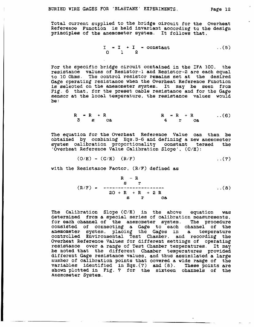
Total current supplied to the bridge circuit for the Overheat Referenoe Function is held invariant according to the design prinoiples of the anemometer system. It follows that,
I = I + I = constant 0 1 2
. . ( 5 )
For the specific bridge circuit contained in the IFA 100, the resistance values of Resistor-1 and Resistor-2 are each equal to 10 Ohms. The control resistor remains set at the desired Gage operating resistance when the Overheat Reference Function is selected on the anemometer system. It may be seen from Fig. 6 that, for the preset cable resistance and for the Gage sensor at the local temperature, the resistance values would be :
R = R + R 3 S ca
R = R + R . .(6) 4 r ca
The equation for the Overheat Reference Value can then be obtained by combining Eqs.3-6 and defining a new anemometer system calibration proportionality constant termed the ‘Overheat Reference Value Calibration Slope’, (C/H):
(O/H) = (C/H) (R/F)
with the Resistance Factor, (R/F) defined as
. .(7)
The Calibration Slope (C/H) in the above equation was determined from a special series of calibration measurements, for each channel of the anemometer system. The procedure consisted of connecting a Gage to each channel of the anemometer system, placing the Gages in a temperature controlled Environmental Test Chamber, and recording the Overheat Reference Values for different settings of operating resistance over a range of Test Chamber temperatures. It may be noted that the different Chamber temperatures provided different Gage resistance values, and thus assimilated a large number of calibration points that covered a wide range of the variables identified in Eqs.(7) and (8). These points are shown plotted in Fig. 7 for the sixteen channels of the Anemometer System.

BURIED WIRE GAGES FOR 'BLASTANE' EXPERIMENTS. Page 13
At a first glance, the spread among different points in Fig. 7 may look like a high level of scatter in calibration measurements, but it must be noted that the spread aatually represents the different Calibration Slope values among the sixteen ohannels of the anemometer system and doe6 not neoessarily reflect the amount of soatter in the calibration measurements.
Calibration points corresponding to each channel of the anemometer system were individually grouped together, and a least squared line fit was determined to finally obtain the slope represented by those points. The Calibration Slope (C/H) values obtained for the different channels are given in Fig. 7.
Next, in an effort to demonstrate the validity of the Calibration Slope (C/H) values for a larger range of Resistance Factor values, calibration measurements were extended for a few channels using different sensors, in the form of hot wire probes. The results of these calibrations are shown in Fig. 8, from which it is clear that the Calibration Slope values remain unaltered for the entire range of Resistance Factors values.
3.2.3 SQUARE WAVE TEST TECHNIQUE
An important part of the operation of the constant temperature anemometer system was the adjustment of the different controls to obtain a high dynamic response to possible fluctuations in flow past the sensor. The IFA 100 Anemometer system had a special feature for introducing a square-wave test signal into the anemometer bridge circuit. Response of the system could be visually verified on an oscilloscope and also used as a basis to optimize the frequency response of the anemometer system, for any given sensor. The amplitude and frequency of the test signal could be continuously varied. Optimization of the response was achieved by proper adjustments of the BRIDGE COMPENSATION AND CABLE COMPENSATION controls on the Anemometer System, as described in the operational manual [Ref. 51. A typical optimized response is shown in Fig. 6. Excellent response to flow fluctuations at the sensor would be achieved if the pulse i s short and without undershoot. The cutoff frequency for the anemometer system-sensor combination may then be evaluated from the time interval t' which is defined as the time from the start of the pulse until the pulse has deoayed to 3% of its maximum value.
1 CUTOFF FREQUENCY = -------
1.5 t'

BURIED WIRE GAGES FOR ‘BLASTANE’ EXPERIMENTS. Page 14
3 . 2 . 4 OUTPUT SIGNAL CONDITIONING
The output s i g n a l of the Anemometer System oould be oonditioned f o r oonvenience of f u r t h e r i n t e r p r e t a t i o n . The anemometer system was equipped with a s i g n a l condi t ioner that could o f f s e t , amplify, and f i l t e r the output s i g n a l before t ransmi t t ing t o e x t e r n a l s i g n a l a c q u i s i t i o n and processing equipment. The s i g n a l condi t ioner fea tured keypad e n t r y f o r s e l e c t i v e d i g i t a l d i sp l ay of o f f s e t . g a i n , and f i l ter values f o r each channel.
3.3 ENVIRONMENTAL TESTING CHAMBER
The c a l i b r a t i o n procedure f o r determining t h e Conduction Loss F a c t o r ‘ A ’ of Eq.(2) required a constant temperature no-flow environment, i n which the Gages could be placed and connected v i a cables t o the anemometer system. Such an environment was ava i l ab le i n an e x i s t i n g Environmental T e s t Chamber. The temperature within the chamber could be set f o r any value w i t h i n the range of -73.0 deg.C t o +315.0 deg.C, and that temperature would be maintained t o within k O . 1 deg.C. I n order t o achieve temperatures below ambient, the chamber used l i q u i d ni t rogen as the coolant .
4 . CALIBRATION PROCEDURE
The governing equat ions f o r the Buried Wire Gage Technique, explained i n Chapter 2 of t h i s r e p o r t , called f o r determination of the c a l i b r a t i o n cons tan ts A and B. I n a d d i t i o n , the l o c a l flow temperatures [such as the ‘ w a l l f l o w recovery’ temperature] needed t o be der ived from measurements of Gage r e s i s t a n c e values [see Eq.(2)1. A c a l i b r a t i o n procedure was the re fo re required t o determine the Gage r e s i s t ance temperature l a w as w e l l as t h e f a c t o r s A and B. The c a l i b r a t i o n procedure thus involved three s t e p s , described i n the following paragraphs.
4 .1 GAGE RESISTANCE TEMPERATURE LAW
The first s t e p of t h e c a l i b r a t i o n procedure was determination of t h e Temperature Coeff ic ient of Resistance and the standard r e s i s t ance value, which def ine the Gage r e s i s t a n c e temperature l a w as given below.
R - R [ I + K ( T - T ) I s t d s t d
To determine these c a l i b r a t i o n cons tan ts , each Gage was brought t o s e v e r a l chosen temperatures i n the EnVirO1~18ntal T e s t i n g Chamber. The r e s i s t ance of each age was measured, using t h e null-balance f ea tu re of the Anemometer System, at each chosen temperature. The r e l a t i o n between temperature and
n
BURIED WIRE GAGES FOR 'BLASTANE' EXPERIMENTS. Page 15
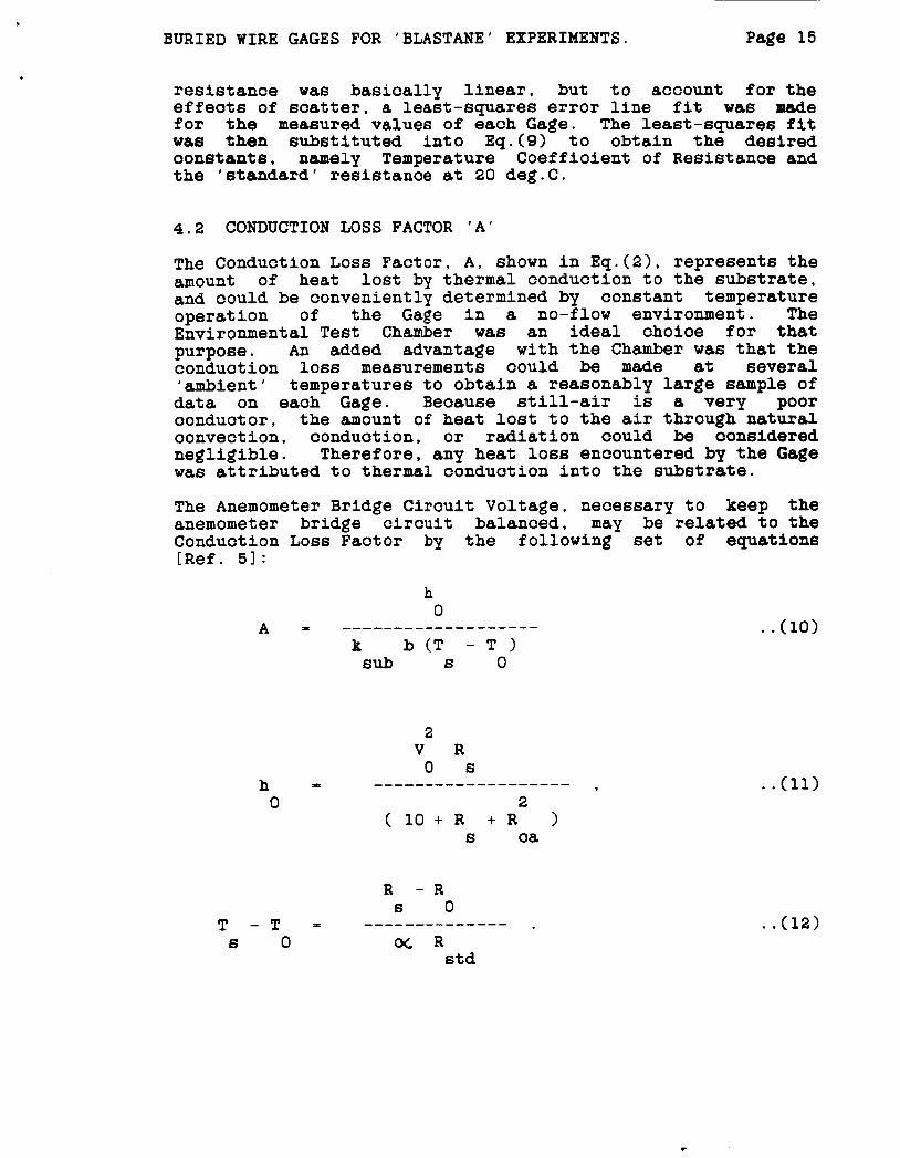
resistance was basically linear, but to account for the effeots of scatter, a least-squares error line fit was made for the measured values of each Gage. The least-squares fit was then substituted into Eq.(9) to obtain the desired oonetants. namely Temperature Coefficient of Resistance and the 'standard' resistance at 20 deg.C.
4.2 CONDUCTION LOSS FACTOR 'A'
The Conduction Loss Factor, A , shown in Eq.(2), represents the amount of heat lost by thermal conduction to the substrate, and could be conveniently determined by constant temperature operation of the Gage in a no-flow environment. The EnviroMental Test Chamber was an ideal choice for that purpose. An added advantage with the Chamber was that the conduction loss measurements could be made at several 'ambient' temperatures to obtain a reasonably large sample of data on each Gage. Because still-air is a very poor conductor, the amount of heat lost to the air through natural convection, conduction, or radiation could be oonsidered negligible. Therefore, any heat loss encountered by the Gage was attributed to thermal conduction into the substrate.
The Anemometer Bridge Circuit Voltage, necessary to keep the anemometer bridge circuit balanced, may be related to the Conduction Loss Factor by the following set of equations [Ref. 51:
. . (10)
. . (11)
. . (12)
BURIED WIRE GAGES FOR 'BLASTANE' EXPERIMENTS. Page 16
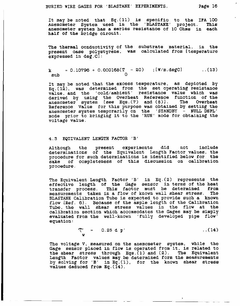
It may be noted that E q . ( l l ) is s p e c i f i c t o the IFA 100 Anemometer System used i n the 'BLASTANE' pro jec t . This anemometer system has a series r e s i s t a n c e of 10 Ohms i n each half of the bridge c i r c u i t .
The thermal conduct iv i ty of the substrate material, i n the present oase polystyrene, was ca l cu la t ed from [temperature expressed i n deg.CI:
k = 0.10796 + 0.000168(T - 20) ;[W/m.degC] . . (13) sub 0
It may be noted that t h e excess temperature , as depicted by Eq.(12) , was determined from the set opera t ing res i s tance va lue , and the 'cold/ambient ' r e s i s t a n c e value which w a s der ived by using the Overheat Reference func t ion of the anemometer system [see Eqs.(7) and (811. The Overheat Reference Value f o r t h i s purpose w a s obtained by s e t t i n g the anemometer system temporarily on the 'STANDBY - NULL DSPL' mode p r i o r t o br inging it t o the ' R U N ' mode f o r obtaining the vol tage va lue .
4 . 3 EQUIVALENT LENGTH FACTOR ' B '
Although the present experiments did not include determinat ions of the Equivalent Length Factor va lues , t he procedure f o r such determinat ions is i d e n t i f i e d below f o r the sake of completeness of t h i s d i scuss ion on c a l i b r a t i o n procedure.
The Equivalent Length Factor ' B ' in Eq.(2) represents the e f f e c t i v e length of t h e Gage sensor i n terms of t h e heat t r a n s f e r process . T h i s f a c t o r must be determined from measurements taken i n a flow of known w a l l shear stress. The BLASTANE Cal ibra t ion Tube is expected t o provide such a known flow [ R e f . 61. Because of t h e ample l eng th of the Cal ibra t ion T u b e , the w a l l shear stress values i n the flow at the c a l i b r a t i o n s e c t i o n which accommodates t h e Gages may be simply evaluated from the well-known ' f u l l y developed pipe flow' equation :
T = 0.25 d p ' W
. . (14)
The vol tage V, measured on t h e anemometer system, while the Gage sensor placed i n flow is operated from i t , is related t o the shear stress through E q s . ( l ) and ( 2 ) . The Equivalent Length Factor va lues may be determined form the measurements by solving f o r ' B ' i n E q . ( l ) , f o r the known shear stress values deduced from Eq.(14).

BURIED WIRE GAGES FOR 'BLASTANE' EXPERIMENTS. Page 17
Eqs.(l) and (2) are reproduced below for quick referenoe:
. . (16)
. . (17)
The additive constant '10' in the denomenator of Eq.(l7) is the value of the resistance in series with the sensor in the anemometer bridge circuit. The different variables in Eqs.(l5) to (1'7) may be derived as follows:
T : calculated from R , using Eq.(9). S 6
; [deg.Cl
T : calculated from R , using Eq.(9). R is obtained from
Eqs.(7) and (8). for the Overheat Reference Value (O/H) obtained from the anemometer system with controls set at the operating resistance and operational mode set on 'STANDBY'-'NULL DSPL', flow passing over the Gage.
r r r
: calculated for the operating temperature[in deg.Cl from P standard air property relationships:
0.?6 = .00000188 ((2'73 + T 1 / 300) ;[kg.sec/sq.ml.
S
k : calculated for the flow recovery temperature { i n deg.C)
= 0.10'796 + O.O00168(T - 20) ;[W/m.degC]. Sub
r
k : calculated for Gage operating temperature {in deg.C)
= 0.02615 + 0.0000759 (T - 2'7) 6
;[W/m.degCl.

BURIED WIRE GAGES FOR 'BLASTANE' EXPERIMENTS. Page 18
5. RESULTS AND DISCUSSION
In all, a total of 121 Buried Wire Gages built into 23 BLASTANE Instrument Plugs were calibrated using the IFA 100 Anemometer system and the Environmental Test Chamber. The calibrations of Gage Resistance versus Temperature were performed for Test Chamber temperature settings of 60, 50, 40, 35, 20, 10 and 0 deg.C. A typical result of this phase of calibration appears in Fig. 9.
The calibrations of Conduction LOSS Factor were performed for Operating Resistance Settings corresponding to 60 deg.C and 50 deg.C, and Test Chamber settings of 35 deg.C and 5 deg.C. In some cases, calibrations were also made with the Test Chamber controls turned off and the Gages open to room ambient temperature.
It may be relevant to note here that, during earlier calibration experiments, a rather high level of soatter was observed in the measurements of Conduction Loss Factors. This was subsequently attributed to the circulating flow produced by the Test Chamber circulation fans which were intended to help maintain a uniform temperature across the entire volume of the Chamber. Although the flow helped achieve a uniform temperature environment, it had the undesirable effect of causing convective heat transfer form the Gages and thus introducing a high level of scatter among different measurements performed at different Chamber temperature settings. This problem was rectified by turning the circulation fans off for a short duration while voltage readings were taken on the Anemometer System.
The expected linear relationship between resistance and temperature for the Gage sensor was borne out by the calibrations, as typically shown in Fig. 9. The 'standard' resistance value and the Temperature Coefficient of Resistance value for each Gage were determined from this line fit and are listed in Table 1.
The Conduction Loss Factor calibrations for the different Gages were found to be typical to those shown in Fig. 10. The scatter that appears in the different calibration points of the same Gage is of the order of 3% peak to peak. This level of soatter is comparable to what was found in previous experiments performed by Murthy and Rose [Ref. 31. who used similar Gages. The average Conduction Loss Factor values for the different Gages appear in Table 1.

BURIED WIRE GAGES FOR 'BLASTANE' EXPERIMENTS Page 19
6 . CONCLUDING REMARKS
Buried Wire Gages were developed f o r use in t ,e Boundary Layer Apparatus f o r Subsonic and Transonic flow Affeoted by Noise Environment ('BLASTANE'). These Gages were of a new type and s p e c i a l oar8 had t o be taken t o bui ld reliable and robust Gages. Detailed s t u d i e s were undertaken t o i d e n t i f y a proper f a b r i c a t i o n method f o r making reliable Gages.
S t a r t i n g from the governing equations of f l u i d flow and the the analogy between momentum and heat transfer processe6, a c a r e f u l l y thoughtout c a l i b r a t i o n procedure was evolved t o render the Gage6 useful as reliable flow measuring d e V i O e 6 when operated from a constant temperature anemometer system. The c a l i b r a t i o n prooedure wa6 i d e n t i f i e d t o cons is t of three d i s t i n c t s t e p s t o determine the three c a l i b r a t i o n f a c t o r s , namely Temperature Coeff ic ient of Resistance, Conduction Loss Fac to r , and Equivalent Length Factor .
Several stages i n the c a l i b r a t i o n procedure callef!,,,z+r determinat ion of the unheated ( ' c o l d ' ) sensor e l emen t r so t at t h i s r e s i s t a n c e would then become a measure of the l o c a l flow temperature a t the w a l l . This r e s i s t a n c e determination oould be conveniently accomplished from a s p e c i a l f e a t u r e oalled the 'Overheat Reference Function' of the IFA-100 Anemometer system used in the present experiments. However, the suppl ie r of the Anemometer System had not provided any c a l i b r a t i o n f o r t h i s func t ion . In order t o a r r i v e at such a c a l i b r a t i o n , the governing equat ions of the anemometer bridge o i r c u i t were rearranged t o i d e n t i f y the proper c o r r e l a t i n g var iab les i n terms of the oirouit elements. T h i s led t o the d e f i n i t i o n of a new parameter oalled 'Resistanoe Faotor' t o represent the ' c o l d ' r e s i s t a n c e i n the c a l i b r a t i o n law. A series of measurements were then m a d 8 w i t h Buried Wire Gages a6 sensors t o de r ive the oa l ib ra t ion constant f o r the funot ional r e l a t i o n s h i p between t h e Overheat Reference Value and the newly def ined 'Resistanoe F a c t o r ' . The measurements were repeated f o r each channel of t h e Anemometer System t o ob ta in the corresponding c a l i b r a t i o n constant . F i n a l l y , v a l i d i t y of t h i s c a l i b r a t i o n law f o r a wide range of r e s i s t ance values was demonstrated by a series of measurements wi th d i f f e r e n t seneor elements.
Although the Gages had been fabricated w i t h great care, the c a l i b r a t i o n s differed s i g n i f i c a n t l y from one Gage t o the o ther . T h i s , in any case, is t y p i c a l of t h i s type of flow measuring instrumentation which measures f l u i d flow parameters through the analogy between momentum t r a n s f e r and heat t r a n s f e r mechanisms. Several c a l i b r a t i o n s have been performed f o r each Gage t o obtain an apprec ia t ion of the unmertainties i n the c a l i b r a t i o n equipment and method. Scatter anong the d i f f e r e n t c a l i b r a t i o n s of each Gage appears t o be within acoeptable l i m i t s and typ ica l t o measurements made previously with similar Wges. Typical r e s u l t s of the c a l i b r a t i o n s are presented in the different Figures.

BURIED WIRE GAGES FOR 'BLASTANE' EXPERIMENTS. Page 20
7. ACKNOWLEDGMENTS
The authors wish to thank Mr. Fred R. Lemos for his sincere and persistent efforts during the development of a proper method to fabricate the Buried Wire Gages used in the present series of oalibration experiments. Thanks are also due to Miss. Anne-Marie Salmi and Mr. Ken Gee who performed much of the calibration measurements.
8. REFERENCES
1. Murthy, S.V. and Steinle, F.W., " Effect 6 of Compressibility and Free-stream Turbulence on Boundary Layer Transition in High Subsonic and Transonic Flows", A I M Paper 86-0764, West Palm Beach, FL., March 1986.
2. Steinle, F . W . and Murthy, S.V., "Boundary Layer Apparatus for Subsonic and Transonic flow Affected by Noise Environment", report under preparation, Aerodynamic Facilities Branch, NASA Ames Research Center, Moffett Field, CA, July 1986.
3. Murthy, S . V . and Rose, W.C., "Buried Wire Gage for Wall Shear Stress Measurements", AIAA Paper 78-798, San Diego, CA, April 19-21, 1978.
4. Lemos. F.R., "Fabrication of Buried Wire Gages for use in Fluid Flow Wall Shear Stress Measurements", Internal Report, Mechanical Instrument Machining Branch [ETMI, NASA Ames Research Center. Moffett Field, CA, March 1986.
5. TSI Incorporated, "IFA 100 Intelligent Flow Analyzer (Constant Temperature Anemometer System) - Instruction Manual", TSI P/N 1990237, TSI Incorporated, 500 Cardigan Road, P.O.Box 64394, St Paul, MN 55164, 1983.
6. Aerodynamic Facilities Branch, "BLASTANE - Safe Operating Procedure", Internal Report, Aerodynamic Facilities Branch, Aerodynamics Division, NASA Ames Research Center, Moffett Field, CA, under review, August 20, 1986.

BURIED WIRE GAGES FOR 'BLASTANE' EXPERIMENTS. Page 21
GAGE NO.
6 7 8 9 10
11 12 13 14 15
16 17 18 19 20
21 22 23 24 25
26 27 28 29 30
31 32 33 34 35
36 37 38 39 40
TABLE-1 : SUMMARY OF BURIED WIRE GAGE CALIBRATIONS
RESISTANCE TEMPERATURE RESISTANCE CONDUCTION AT COEFF OF AT Loss
20 DEG.C RESISTANCE 60 DEG.C FACTOR.
--------- ( Ohm6 ( 1deg.C) (Ohm6 _-----____ -___-___-- --___-----
5.627 0.00370 6.468 1.434 5.566 0.003'13 6.403 1.520 5.811 0.00376 6.693 1.524 5.702 0.00377 6.577 1.469 5.835 0.00371 6.701 1.498
5.668 0.00375 6.523 1.399 5.675 0.00372 6.524 1.472 5.469 0.00374 6.297 1.406 5.512 0.00377 6.350 1.533 5.371 0.00377 6.190 1.542
5.506 0.00371 6.323 1.429 1.448 5.522 0.00373 6.346
5.587 0.00374 6.424 1.473 5.849 0.00375 6.734 1.497 5.589 0.00372 6.418 1.459
5.634 0.00382 6.514 1.422 5.841 0.00380 6.753 1.479 5.496 0.00383 6.361 1.481 5.528 0.00383 6.403 1.441 5.658 0.00382 6.545 1.488
5.669 0.00382 6.547 1.488 5.619 0.00383 6.495 1.432 5.590 0.00374 6.437 1.390 5.543 0.00379 6.394 1.530 5.569 0.00384 6.440 1.329
5.276 0.00375 6.083 1.444 5.592 0.00374 6.437 1.418 5.417 0.00381 6.255 1.425 5.649 0.00377 6.514 1.387 5.355 0.00377 6.175 1.521
1.426 5.561 0.00373 6.401 5.645 0.00384 6.521 1.418 5.345 0.00372 6.152 1.353 5.534 0.00378 6.379 1.473 5.582 0.00368 6.433 1.360
5.464 0.00385 6.319 1.465 5.481 0.00411 6.383 1.640 5.716 0.003'19 6.597 1.463 5.347 0.00382 6.182 1.407 5.533 0.00376 6.375 1.416

BURIED WIRE GAGES FOR 'BLASTANE' EXPERIMENTS. Page 22
GAGE NO.
----
41 42 43 44 45
46 47 48 49 50
51 52 53 54 55
56 57 58 59 60
61 62 63 64 65
66 67 68 69 70
71 72 73 74 75
76 77 78 79 80
RESISTANCE
20 DEG.C ( Ohm6
AT
----------
5.849 5.897 5.517 5.684 5.476
5.520 5.540 5.711 5.768 5.542
5.540 5.902 5.724 5.764 6.089
5.731 5.368 5.684 5.569 5.811
5.819 5.553 5.930 5.590 5.464
5.992 5.832 5.761 5.987 5.412
5.447 5.817 5.831 5.597 5.751
5.242 5.600 5. '720 5.641 5.513
TABLE-1 (Continued)
TEMPERATURE RESISTANCE COEFF OF RES1 STANCE ( /deg . C)
0.00379 0.00374 0.00370 0.00368 0.00369
0.00374 0.00370 0.00363 0.00356 0.00371
0,00366 0.00378 0.00376 0.00369 0.00377
0.00376 0.00364 0.00365 0.00365 0.00379
0.00372 0.00372 0.00374 0.00373 0.00364
0.00371 0.00380 0.003'11 0.00367 0.00368
0.00374 0.00367 0.00368 0.00370 0.00369
0.00374 0.00363 0.00372 0.00374 0.00382
__--------
AT 60 DEG.C
( Ohm6
6.753 6.788 6.342 6.531 6.290
6.351 6.367 6.547 6.593 6.367
6.354 6. 796 6.603 6.625 7.021
6.607 6.156 6.519 6.390 6.703
6.678 6.385 6.825 6.429 6.263
6.878 6.726 6.625 6.877 6.215
6.270 6.675 6.698 6.427 6.603
6.031 6.416 6.573 6.491 6.356
CONDUCTION Loss FACTOR.
--_---__--
1.632 1.572 1.579 1.586 1.537
1.573 1.593 1.560 1.558 1.627
1.537 1.586 1.652 1.631 1.619
1.643 1.490 1.571 1.516 1.663
1.547 1.567 1.610 1.567 1.585
1.665 1.624 1.586 1.538 1.509
1.549 1.556 1.591 1.601 1.622
1.588 1.416 1.535 1.558 1.500
BURIED WIRE GAGES FOR 'BLASTANE' EXPERIMENTS.
GAGE NO.
_---
81 82 83 84 85
86 87 88 89 90
91 92 93 94 95
96 97 98 99 100
101 102 103 104 105 106 107
108 109 110 111 112 113 114
115 116 117 118 119 120 121
RES I STANCE
20 DEG.C ( Ohms
AT
----------
5.635 5 .?52 5.464 5.766 5.358
5.540 5.784 5.651 5.441 5.716
5.651 5.733 5.633 5.641 5.431
5 .702 5.675 5.890 5.643 5.611
5.883 5.824 5.733 5.815 4.066 3.815 3.936
5.543 5.309 5.540 5.486 4.033 9.725 3.548
5.599 5.639 5.658 5.615 3. 759 3.577 3.846
TABLE-1 (Continued)
TEMPERATURE RESISTANCE COEFF OF RES1 STANCE ( /deg.C)
0.00371 0.00360 0.00372 0.00372 0.00359
0.00376 0.00373 0.00386 0.00377 0.00367
0.00377 0.00383 0.003'15 0.00381 0.00383
0.00380 0.00377 0.00376 0.00372 0.00388
0.00372 0.003'74 0.00381 0.00389 0.00365 0.00369 0.00377
0.00368 0.00381 0.00390 0.00370 0.00357 0.00362 0.00372
0.00378 0.00379 0.00380 0.00378 0.00360 0.00364 0.00374
____-_----
AT 60 DEG.C
( ohms 1
6.479 6.588 6.286 6.631 6.155
6.388 6.601 6.538 6.271 6.576
6.508 6.617 6.481 6.510 6.268
6.576 6.545 6. 779 6.488 6.4'19
6. 757 6.694 6.606 6. 721 4.660 4.378 4.529
6.359 6.117 6.403 6.298 4.609 4.265 4.075
6.446 6.494 6.518 6.462 4.301 4.099 4.421
CONDUCTION Loss FACTOR.
1.477 1.457 1.486 1.610 1.342
1.480 1.495 1.445 1.435 1.429
1.559 1.454 1.432 1.496 1.524
1.498 1.465 1.508 1.483 1.611
1.546 1.557 1.554 1.670 1.704 1.679 1.727
1.559 1.480 1.506 1.494 1.994 1.676 1.694
1.472 1.419 1.494 1.468 1.580 1.628 1.754

SCHEMATIC OF BURIED WIRE GAGE TECHNIQUE
EDGE OF BOUNDARY LAYER +-a- /
VELOCITY PROFILE
FLUID FLOW = FLOW SUR FACE
BOUNDARY TH I C KN ESS,
LAYER s
BURIED ' HOT ' WIRE SENSOR \ SUBSTRATE INSERT
ALUMINUM INSTRUMENT CABLE LEADING TO PLUG BLANK ANEMOMETER SYSTEM
Figure 1
> E
(9 P
I
w A m 3 a - a 8 X
' W
A /
K 3 I
z E
A -' a -

CY LlNDRlCAL ADAPTERS TO POSITION ELECTRICAL L DURING INJEC MOLDING
SUBSTRATE INSERT FABRICATION STAGES b ' * 7
4L
RICAL
I NJECTI ON- MOLDED SUBSTRATE BLANK, STILL ATTACHED TO CY LlNDRlCAL ADAPTERS
IN JECTl ON-
d MOLDED SUBSTRATE BLANK
SUBSTRATE INSERT AT DIFFERENT STAGES OF FABRICATION
TRATE I I I N G BLI
Fig1
NSE DC K
ire
RT
3
SUBSTRATE-HOLDER AND POLISHING STONE
b

ORIGWAL w W R
INSTRUMENT PLUG BLANK WITH BURIED WIRE GAGES
L
CABLE
SUBSTF .MOUNT IURED P
PLUG BLANK WITH 5 GAGES
POLY- STYRENE SUBSTRATE
\
LEADS
3ATE 'ED 'LUG
'HOT' WIRE SENSOR (3.8 pm diam TUNGSTEN) WELDED TO ELECTRICAL LEADS
TO THE SUBSTRATE SURFACE
AND SOLVENT-BON DED
ELECTRICAL LEADS (0.38 mm diam NICKEL)
MAGNIFIED VIEW OF A BURIED WIRE GAGE
Figure 4

-- I",-_"

’ ‘< . ‘“‘ANEMOMETER BRIDGE ANT) TEST SIGNAL CIRCUIT , A * # ;irpP;i y
SQUARE-WAVE TEST SIGNAL GENERATOR
.%- - 1 AMPLIFIED OFF-BALANCE m----- -4- ’ - 7 I (OVERHEAT REFERENCE) I
0 GAGE SENSOR
(a) ANEMOMETER BRIDGE CIRCUIT AND FEEDBACK SYSTEM
UNFILTERED SIGNAL
FILTERED SIGNAL
4 +20 micro-see
(b) OSCILLOSCOPE TRACE OF SQUARE WAVE TEST SIGNAL RESPONSE
Figure 6

A
A S raplb
Fa
I I I I I I
%kxnal 0
Y, 9
- 0 0 0 0 0 0 0 0 0 0 0 0 0
Io 0 In 0 m N N 2 41
* 9
- n 3 - 0 0
Y,
0 0 0 0 0
0 0 0 0 In 0 0 N N 2 0,
0
B s y
*
8

I I I I I I I I I I I I i
n
% % .
% P O k.
.. I 0 b,
0 0 0 0 0 0 0 0 0 0 0 0 0 0 0 0 0 0 0 0 0 0 0 0 0 0 0 0 0 o u 3 o r o o u a l - c D a u a u 3 * s % ~ ~ ~ : 2 u 3
0 0 0 0
0 O O 0 0 0 0
0 0 0 o o 0 0 % 0 5 1 0 2 - 0
0 0 0 m g 2
0 In In 5: P 0
lD 0
L
c
9
8

.

u3 CD I
Q, cu
- 0 o m
0 o a m a w
0 0 0 0 O a D O
OD 0-
o m o o m o
m0 m m
V '11013Vd SSOl N0113naN03
0 00 0
030 00
0 m o m
0 3 OD0
I I I I
Ir! c)
'9 I
v ' I l O U V 1 ssm NOWnaN03
s I