Embed Size (px)
Citation preview
Korean J. Chem. Eng., 24(2), 332-335 (2007)
SHORT COMMUNICATION
332
†To whom correspondence should be addressed.
E-mail: [email protected]‡This paper was presented at the 6th Korea-China Workshop on Clean
Energy Technology held at Busan, Korea, July 4-7, 2006
Development of building materials by using micro-encapsulated phase change material
See Hoon Lee, Sang Jun Yoon, Yong Gu Kim, Young Chan Choi, Jae Ho Kim and Jae Goo Lee†
Korea Institute of Energy Research, Daejeon 305-343, Korea(Received 26 August 2006 • accepted 21 October 2006)
Abstract−Micro-encapsulated phase change material (Micro-PCM) could be used for high density thermal energy
storage and also for PCM-building materials. Micro-PCM was prepared by in-situ polymerization at 60 oC after the
emulsifying step by using 5 wt% Styrene Maleic Anhydride (SMA) solution as an emulsifier. The particle size of Micro-
PCM decreased and the size uniformity was improved with an increase of the mixing intensity during emulsification.
The average diameter of Micro-PCM was 5-20 µm. The thermal fluctuation of PCM-building materials such as gypsum
and olefin film mixed with Micro-PCM was smoother and smaller than typical building materials without PCM.
Key words: PCM, Thermal Energy Storage, Building Material
INTRODUCTION
Latent heat storage material that is called as phase change materials
(PCMs), has been a main topic in thermal energy storage (TES) for
the last 20 years. With no agglomeration during PCM solidification,
microcapsules can be used to store the latent heat storage material
[1-4]. The thermal energy storage and heat exchange systems are
mainly made up by using sensible heat materials such as water. In
recent years, however, new materials for transportation as well as
storage of energy by latent heat are under development such as ice
slurries, micro-encapsulated phase change materials and micro-emul-
sion [5]. The new technologies are more effective than conventional
systems that are only using sensible heat. Especially due to PCM
segregation even during the phase change stage in microcapsule,
the newly developed Micro-PCM have higher capacity of heat stor-
age and transportation than the conventional ones [5-8]. Therefore,
the system operation cost by using Micro-PCM might be lower than
for a conventional system. And with the advent of PCM implemented
in gypsum board, plaster, concrete or other wallboard material, ther-
mal storage can be a part of construction technology for light weight
buildings [9].
In the micro-encapsulation process, the emulsifier as a modifier
used for forming shell structure was induced to be separated from
a new, viscous, polymer-rich phase by adding a nonsolvent or a sec-
ond polymer, lowering the encapsulating temperature, controlling
pH, and other operating conditions. It is essential to control condi-
tions that would cause the polymer to come out of the solution and
to aggregate around the core droplet to form the microcapsule shell
[5].
In the present study we used hexadecane or octadecane as core
materials and melamine-formaldehyde as a shell material for the
production of Micro-PCM for PCM-building material. And the char-
acteristics of Micro-PCM and the heat storage capacity of PCM-
building materials were determined.
EXPERIMENTAL
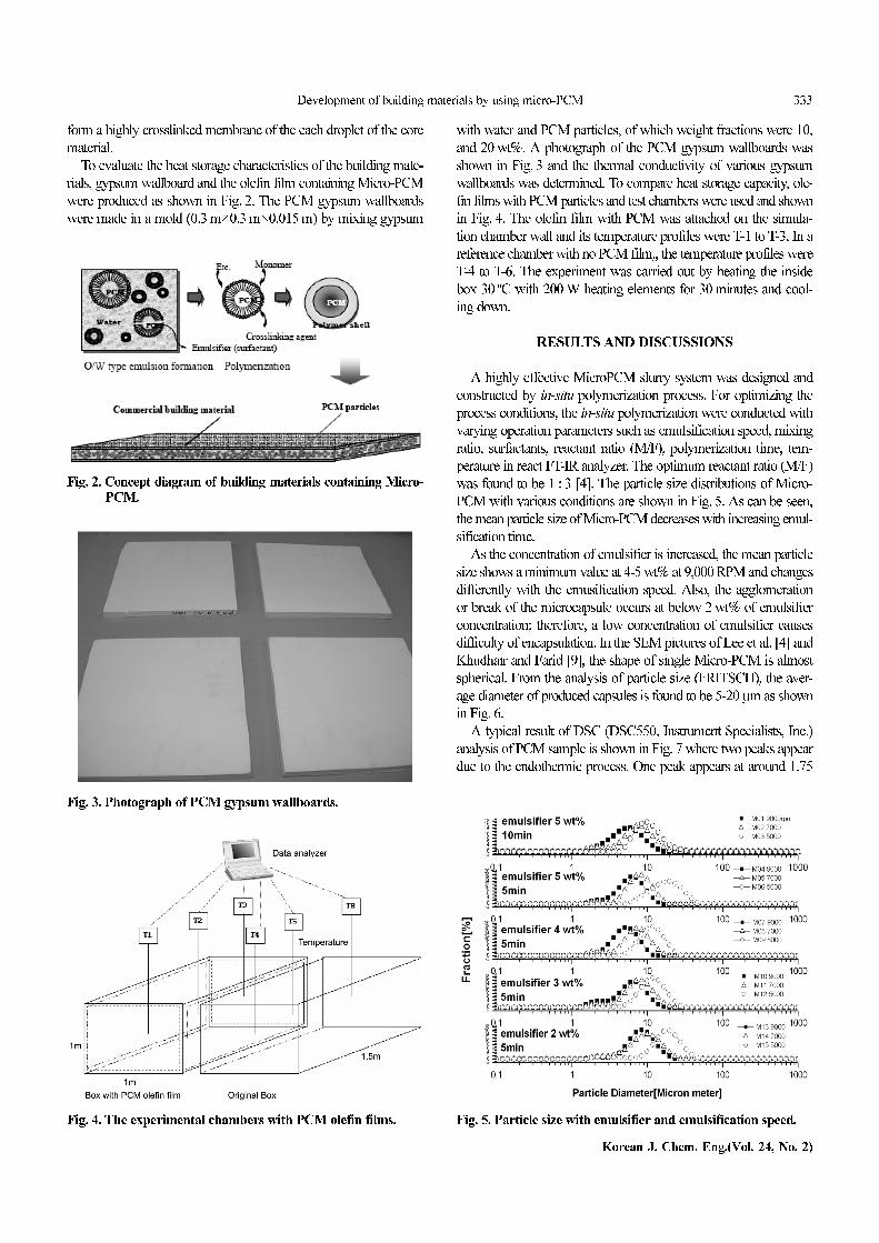
To prepare the Micro-PCM, in-situ micro-encapsulation process
was used as shown in Fig. 1. Hexadecane (C14H36) or octadecane
(C18H38) was used as a core material having melting temperature of
23 oC and 26 oC, respectively, and melamine-resin was used as a
shell material. At the first process core material was emulsified in
the solution which was prepared by homomixer (ME100LC, ROSS).
Also melamine-formaldehyde (MF) prepolymer was made by heat-
ing an aqueous MF mixture at pH of 8.0-8.5 and 60 oC for 1 h. Mel-
amine reacts with up to six molecules of formaldehyde under slightly
alkaline conditions to melamine methylol derivatives that contain
six methylol groups per melamine molecules. When heated, the
methylol-melamine is condensed to form a crosslinked structure
[5]. A known amount of SMA was dissolved at 60 oC to make 5 wt%
solution, and then cooled down to room temperature. SMA solu-
tion was mixed with a mixture of hexadecane, octadecane and water
for 10 minutes by homomixer. To control the capsule size and to
make stabilized droplets, the speed of homomixer was regulated from
3,000 to 10,000 rpm. Finally, emulsified core material was mixed
into the acidified aqueous melamine-formalin (MF) prepolymer
solution. The polymerization was carried out at 60 oC over 3 h to
Fig. 1. Processes of Micro-PCM production.
Development of building materials by using micro-PCM 333
Korean J. Chem. Eng.(Vol. 24, No. 2)
form a highly crosslinked membrane of the each droplet of the core
material.
To evaluate the heat storage characteristics of the building mate-
rials, gypsum wallboard and the olefin film containing Micro-PCM
were produced as shown in Fig. 2. The PCM gypsum wallboards
were made in a mold (0.3 m×0.3 m×0.015 m) by mixing gypsum
with water and PCM particles, of which weight fractions were 10,
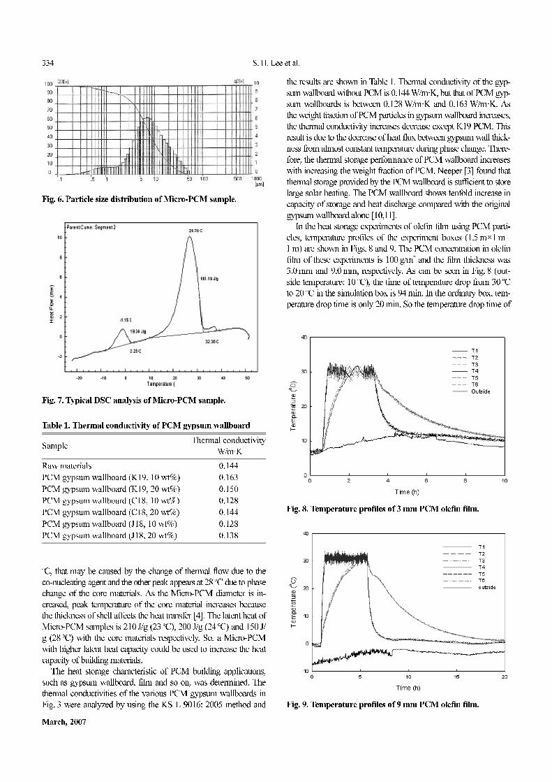
and 20 wt%. A photograph of the PCM gypsum wallboards was
shown in Fig. 3 and the thermal conductivity of various gypsum
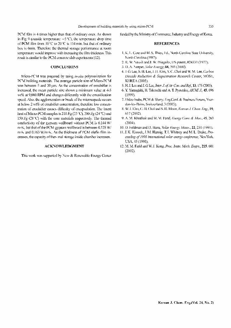
wallboards was determined. To compare heat storage capacity, ole-
fin films with PCM particles and test chambers were used and shown
in Fig. 4. The olefin film with PCM was attached on the simula-
tion chamber wall and its temperature profiles were T-1 to T-3. In a
reference chamber with no PCM film,, the temperature profiles were
T-4 to T-6. The experiment was carried out by heating the inside
box 30 oC with 200 W heating elements for 30 minutes and cool-
ing down.
RESULTS AND DISCUSSIONS
A highly effective MicroPCM slurry system was designed and
constructed by in-situ polymerization process. For optimizing the
process conditions, the in-situ polymerization were conducted with
varying operation parameters such as emulsification speed, mixing
ratio, surfactants, reactant ratio (M/F), polymerization time, tem-
perature in react FT-IR analyzer. The optimum reactant ratio (M/F)
was found to be 1 : 3 [4]. The particle size distributions of Micro-
PCM with various conditions are shown in Fig. 5. As can be seen,
the mean particle size of Micro-PCM decreases with increasing emul-
sification time.
As the concentration of emulsifier is increased, the mean particle
size shows a minimum value at 4-5 wt% at 9,000 RPM and changes
differently with the emusification speed. Also, the agglomeration
or break of the microcapsule occurs at below 2 wt% of emulsifier
concentration; therefore, a low concentration of emulsifier causes
difficulty of encapsulation. In the SEM pictures of Lee et al. [4] and
Khudhair and Farid [9], the shape of single Micro-PCM is almost
spherical. From the analysis of particle size (FRITSCH), the aver-
age diameter of produced capsules is found to be 5-20µm as shown
in Fig. 6.
A typical result of DSC (DSC550, Instrument Specialists, Inc.)
analysis of PCM sample is shown in Fig. 7 where two peaks appear
due to the endothermic process. One peak appears at around 1.75
Fig. 2. Concept diagram of building materials containing Micro-PCM.
Fig. 4. The experimental chambers with PCM olefin films. Fig. 5. Particle size with emulsifier and emulsification speed.
Fig. 3. Photograph of PCM gypsum wallboards.
334 S. H. Lee et al.
March, 2007
oC, that may be caused by the change of thermal flow due to the
co-nucleating agent and the other peak appears at 28 oC due to phase
change of the core materials. As the Micro-PCM diameter is in-
creased, peak temperature of the core material increases because
the thickness of shell affects the heat transfer [4]. The latent heat of
Micro-PCM samples is 210 J/g (23 oC), 200 J/g (24 oC) and 150 J/
g (28 oC) with the core materials respectively. So, a Micro-PCM
with higher latent heat capacity could be used to increase the heat
capacity of building materials.
The heat storage characteristic of PCM building applications,
such as gypsum wallboard, film and so on, was determined. The
thermal conductivities of the various PCM gypsum wallboards in
Fig. 3 were analyzed by using the KS L 9016: 2005 method and
the results are shown in Table 1. Thermal conductivity of the gyp-
sum wallboard without PCM is 0.144 W/m·K, but that of PCM gyp-
sum wallboards is between 0.128 W/m·K and 0.163 W/m·K. As
the weight fraction of PCM particles in gypsum wallboard increases,
the thermal conductivity increases decrease except K19 PCM. This
result is due to the decrease of heat flux between gypsum wall thick-
ness from almost constant temperature during phase change. There-
fore, the thermal storage performance of PCM wallboard increases
with increasing the weight fraction of PCM. Neeper [3] found that
thermal storage provided by the PCM wallboard is sufficient to store
large solar heating. The PCM wallboard shows tenfold increase in
capacity of storage and heat discharge compared with the original
gypsum wallboard alone [10,11].
In the heat storage experiments of olefin film using PCM parti-
cles, temperature profiles of the experiment boxes (1.5 m×1 m×
1 m) are shown in Figs. 8 and 9. The PCM concentration in olefin
film of these experiments is 100 g/m2 and the film thickness was
3.0 mm and 9.0 mm, respectively. As can be seen in Fig. 8 (out-
side temperature: 10 oC), the time of temperature drop from 30 oC
to 20 oC in the simulation box is 94 min. In the ordinary box, tem-
perature drop time is only 20 min. So the temperature drop time of
Fig. 6. Particle size distribution of Micro-PCM sample.
Fig. 8. Temperature profiles of 3 mm PCM olefin film.
Fig. 7. Typical DSC analysis of Micro-PCM sample.
Table 1. Thermal conductivity of PCM gypsum wallboard
SampleThermal conductivity
W/m·K
Raw materials 0.144
PCM gypsum wallboard (K19, 10 wt%) 0.163
PCM gypsum wallboard (K19, 20 wt%) 0.150
PCM gypsum wallboard (C18, 10 wt%) 0.128
PCM gypsum wallboard (C18, 20 wt%) 0.144
PCM gypsum wallboard (J18, 10 wt%) 0.128
PCM gypsum wallboard (J18, 20 wt%) 0.138
Fig. 9. Temperature profiles of 9 mm PCM olefin film.
Development of building materials by using micro-PCM 335
Korean J. Chem. Eng.(Vol. 24, No. 2)
PCM film is 4 times higher than that of ordinary ones. As shown
in Fig. 9 (outside temperature: −5 oC), the temperature drop time
of PCM film from 30 oC to 20 oC is 114 min, but that of ordinary
box is 6min. Therefore the thermal storage performance at room
temperature would improve with increasing the film thickness. This
result is similar to the PCM concrete slab experiments [12].
CONCLUSIONS
Micro-PCM was prepared by using in-situ polymerization for
PCM building materials. The average particle size of Micro-PCM
was between 5 and 20µm. As the concentration of emulsifier is
increased, the mean particle size shows a minimum value at 4-5
wt% at 9,000 RPM and changes differently with the emusification
speed. Also, the agglomeration or break of the microcapsule occurs
at below 2 wt% of emulsifier concentration; therefore low concen-
tration of emulsifier causes difficulty of encapsulation. The latent
heat of Micro-PCM samples is 210 J/g (23 oC), 200 J/g (24 oC) and
150 J/g (28 oC) with the core materials respectively. The thermal
conductivity of the gypsum wallboard without PCM is 0.144 W/
m·K, but that of the PCM gypsum wallboard is between 0.128 W/
m·K and 0.163 W/m·K. As the thickness of PCM olefin film in-
creases, the capacity of ther- mal storage inside chamber increases.
ACKNOWLEDGMENT
This work was supported by New & Renewable Energy Center
funded by the Ministry of Commerce, Industry and Energy of Korea.
REFERENCES
1. K. L. Core and M. S. Thies, Ed., North Carolina State University,
North Carolina (1987).
2. R. W. Neuzil and J. W. Priegnitz, US patent, 024331 (1977).
3. D. A. Neeper, Solar Energy, 68, 393 (2000).
4. J. G. Lee, S. H. Lee, J. H. Kim, Y. C. Choi and W. M. Lee, Carbon
Dioxide Reduction & Sequestration Research Center, MOST,
KOREA (2005).
5. H. J. Lee and J. G. Lee, Inter. J. of Air-Con. and Ref., 13, 175 (2005).
6. Y. Yamagishi, H. Takeuchi and A. T. Pyatenko, AIChE J., 45, 696
(1999).
7. Hideo Inaba, PCM & Slurry: Eng.Conf. & Business Forum, Yver-
don-les-Bains, Switzerland, 3 (2003).
8. W. J. Kim, C. H. Choi and S. H. Moon, Korean J. Chem. Eng., 19,
617 (2002).
9. A. M. Khudhair and M. M. Farid, Energy Conv. & Man., 45, 263
(2004).
10. D. Feldman and D. Banu, Solar Energy Mater., 22, 231 (1991).
11. J. K. Kissock, J. M. Hannig, T. I. Whitney and M. L. Drake, Pro-
ceeding of 1998 international solar energy conference, NewYork,
USA, 45 (1998).
12. M. M. Farid and W. J. Kong, Proc. Instn. Mech. Engrs., 215, 601
(2002).


![Micro-Mechanical Viscoelastic Properties of Crosslinked ......for most soft tissues and biomaterials [27–29]. We suggested that an ideal testing method for deriving We suggested](https://img.pdfslide.us/doc/110x75/60ec7b12d34f663e315d3470/micro-mechanical-viscoelastic-properties-of-crosslinked-for-most-soft-tissues.jpg)