Embed Size (px)
Citation preview
1 / 26
Development of auxetic warp knitted fabrics based on reentrant
geometry
Zhao Shuaiquan, Hu Hong*, Chang Yuping
Institute of Textiles and Clothing, The Hong Kong Polytechnic University, Hung
Hom, Hong Kong
*The corresponding author: [email protected]
Abstract
This paper reports a novel method to fabricate auxetic warp knitted fabrics on a tricot
warp knitting machine based on a special structure design and knitting process. Three
auxetic warp knitted structures were successfully developed and all of them were
designed to form a reentrant hexagonal geometry to acquire auxetic effect. To provide
the fabrics with reentrant frames, both elastomeric yarns and stiff yarns were used to
form the elastic underlaps and stiff underlaps, respectively. While the elastic underlaps
can keep the reentrant structures stable, the stiff underlaps can support the reentrant
structures to keep their reentrant frames. To alleviate the transfer of yarns in the loops
under tension, an additional front yarn guide bar was used to feed binding yarns to basic
reentrant structures. After knitting, all the fabrics were subjected to a heat setting
process to keep their shape and a tensile test to assess their auxetic behavior.
Experimental results showed that all the fabrics exhibited an obvious auxetic behavior
within a wide range of strain. Especially, the fabrics kept an auxetic behavior till
breaking when stretched in wales direction and the Poisson’s ratio of the fabrics could
be as low as -0.5. On the other hand, the fabrics exhibited a large tensile elongation
when stretched in courses direction and their Poisson’s ratio was changed from negative
to positive after the tensile strain exceeded a certain value.
This is the accepted version of the publication Zhao, S., Hu, H., Kamrul, H., Chang, Y., & Zhang, M, Development of auxetic warp knitted fabrics based on reentrant geometry, Textile Research Journal (Volume 90 and Issue 44289) pp. 344-356. Copyright © 2019 (The Author(s)). DOI: 10.1177/0040517519866931.
This is the Pre-Published Version.
2 / 26
Key words
Negative Poisson’s ratio, auxetic fabrics, knitting, auxetic textiles
1. Introduction
Poisson’s ratio is defined as the minus value of materials’ lateral strain to longitudinal
strain under tension [1]. Although most materials possess positive Poisson’s ratio
theoretically and practically, materials with negative Poisson’s ratio (NPR) do exist in
nature [2]. Materials with NPR are also known as auxetic materials [3]. They have
received increasing attention since the report of the first man-made auxetic foam in
1987 [4]. Auxetic materials, usually with a special structure being of either macroscopic
or microscopic, will expand under unidirectional tension [5-7]. Due to this counter-
intuitive behavior, properties of auxetic materials, such as shear resistance [8],
indentation resistance [9], sound absorption [10] and crashworthiness [11, 12] can be
enhanced [7, 13, 14], making them ideal materials for many interesting applications
such as personal protection [15], biomedicine, aerospace and even military use [16].
So far a lot of structures have been proved to be auxetic [17-20] and many of them have
been found to have similar deformation mechanisms [21].
There are mainly two methods to achieve auxetic fabrics. The first one is to use auxetic
yarns to fabricate fabrics with normal structures. Miller et al. [22] reported a type of
auxetic woven fabric made of auxetic yarns for composite reinforcement and proved
that the composite manufactured from two layers of the auxetic fabrics showed auxetic
effect. Wright et al. [23] proposed a woven structure fabricated with helical auxetic
yarns. Although the Poisson’s ratio of the auxetic yarns used was as low as -1.5, the
fabrics made from these auxetic yarns only obtained a Poisson’s ratio of -0.1. Using the
same principle, Ng et al. also [24] fabricated auxetic woven fabrics with different types
of auxetic yarns and found that the auxetic effect of the fabrics depended on several
parameters including yarn arrangements, woven structures and types of helical yarns
used. The limitation of using auxetic yarns to produce auxetic fabrics is that their
3 / 26
auxetic behavior could be restrained by fabric structures.
The second method is to directly fabricate auxetic fabrics from non-auxetic yarns by
realizing special auxetic geometrical structures in fabrics. Several woven fabrics have
been proposed using this method [25-27]. Knitting has also shown its advantage in
fabricating auxetic fabrics using different auxetic geometries. Through flat knitting, Liu
et al. [28] produced auxetic weft knitted fabrics based on a foldable structure comprised
of parallelogram planes. Hu et al. [29] also designed and fabricated three types of
auxetic knitted fabrics based on foldable structures, rotating rectangles and reentrant
hexagons, respectively. In regard to warp knitting, Ugbolue [30, 31] et al. proposed a
type of auxetic structures with the use of thicker soft yarns to form open chain wales
and high stiffness yarns as inlaid yarns. They also suggested a reentrant hexagonal warp
knitted structure by using inlaid elastomeric yarns. Alderson et al. [32] developed
another type of warp knitted fabric with double arrow head structure and found that
NPR could be achieved under ±450 tension. Wang and Hu [14] developed a special type
of auxetic warp knitted spacer fabrics with in-plane auxetic behavior through the
modification of a non-auxetic hexagonal geometry to an auxetic geometry formed with
parallelograms by using thermo-mechanical method. Chang et al. [33] proposed another
type of warp knitted fabric with NPR based on a rotational hexagonal structure and
further applied it to warp knitted spacer fabrics [34]. Although a few auxetic warp
knitted fabrics have been proposed based on different geometries, the number is still
limited and more auxetic warp knitted fabrics can be achieved using novel method to
enlarge their range.
This paper reports the design and fabrication of a novel type of planar auxetic warp
knitted structure based on a modified reentrant hexagonal geometry by using a
conventional high-speed tricot warp knitting machine. It is expected that the newly
proposed auxetic warp knitted structure would have a great potential for practical
applications.
4 / 26
2. Experimental
2.1 Geometry design
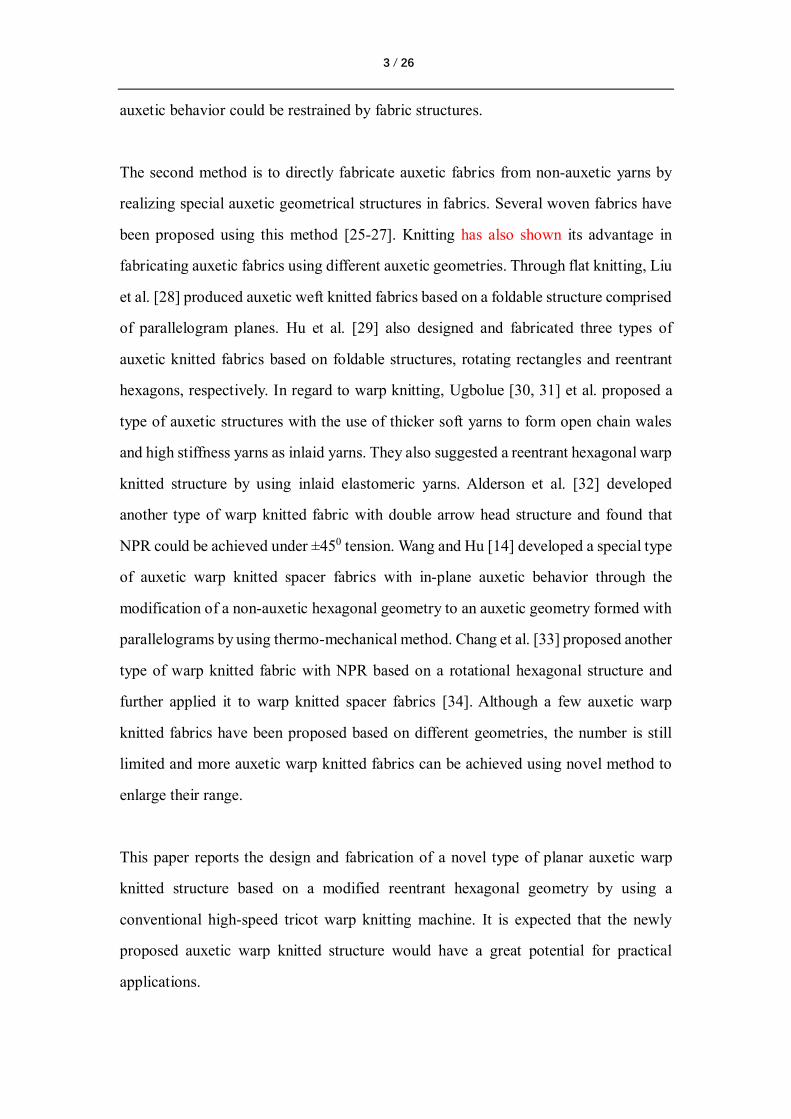
The well-known reentrant hexagonal structure, as shown in Figure 1(a), was adopted as
the basic geometry to form auxetic warp knitted fabrics. As illustrated in Figure 1 (b),
there are two types of ribs in a basic unit of the structure, namely the horizontal ribs
and the diagonal ribs. When subjected to tension in either vertical or horizontal direction,
the horizontal ribs will keep straight, but the diagonal ribs tend to rotate towards the
vertical direction, leading to the lateral extension of the basic unit. As a result, the
auxetic effect is achieved. It should be noted that the ribs can be designed to have
different lengths to achieve different θ for obtaining different auxetic effect.
(a) (b)
Figure 1 Reentrant hexagonal geometry (a) and basic unit (b).
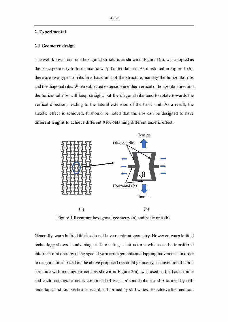
Generally, warp knitted fabrics do not have reentrant geometry. However, warp knitted
technology shows its advantage in fabricating net structures which can be transferred
into reentrant ones by using special yarn arrangements and lapping movement. In order
to design fabrics based on the above proposed reentrant geometry, a conventional fabric
structure with rectangular nets, as shown in Figure 2(a), was used as the basic frame
and each rectangular net is comprised of two horizontal ribs a and b formed by stiff
underlaps, and four vertical ribs c, d, e, f formed by stiff wales. To achieve the reentrant
5 / 26
geometry as shown in Figure 1(a), additional underlaps formed by elastomeric yarns
were introduced to connect two adjacent stiff underlaps horizontally. As shown in
Figure 2(b), stiff underlaps and elastic underlaps are alternatively distributed along both
the wale and course directions. The length and width of both the horizontal and vertical
ribs could be designed through the change of the number of wales or courses in a
repeating unit and the threading way of warp yarns. As shown in Figure 2(c),
elastomeric yarns will shrink after finishing, narrowing the distance between two
adjacent vertical ribs while stiff yarns will support the adjacent vertical ribs to keep a
distance between them due to their high stiffness. As a result, the conventional
rectangular nets were converted into an auxetic reentrant ones. The vertical ribs also
become diagonal ribs. Due to the use of elastomeric yarns, the designed auxetic
geometry can exhibit much better elastic recovery after the load is released.
(a) (b) (c)
Figure 2 Schematic illustration of structural design: (a) conventional rectangular nets;
(b) introducing of elastomeric yarns during knitting process; (c) conversion of
conventional nets into auxetic geometry due to shrinkage of elastomeric yarns.
2.2 Knitting of auxetic warp knitted fabrics
The above designed auxetic geometry can be fabricated with special yarn arrangement
and lapping movements using conventional warp knitting machine. Rigid warp knitted
6 / 26
wales and long underlaps are used to form the vertical ribs and horizontal ribs,
respectively. It should be noted that the width and length of both the vertical and
horizontal ribs can be varied by changing the yarn threading methods and number of
knitting courses in a repeating unit. In this study, to avoid re-threading of yarns which
is time-consuming, the same yarn threading method (2 needles knitting and 2 needles
non-knitting in a repeating unit) were used to produce the auxetic fabric samples with
different numbers of knitting courses for the vertical ribs (V) and horizontal ribs (H) in
a repeating unit to study the influence of the rib size on the auxetic behavior of fabrics.
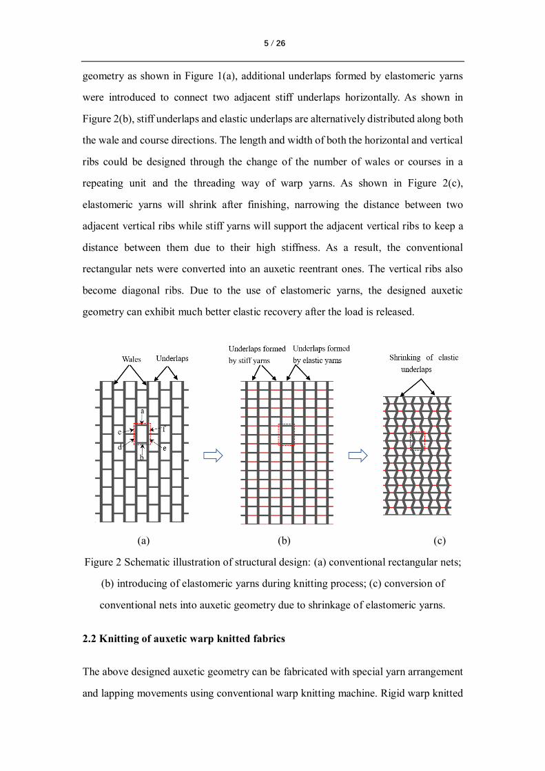
The loop structures of the three fabrics were schematically shown in Figure 3 and their
corresponding chain notations are listed in Table 1. For easy reference, the values of V
and H for each fabric structure are also provided in Table 1. It can be seen that three
yarn guide bars (GBs) were used. While the first yarn guide bar (GB1) was used to knit
open chain stitches to stabilize the ground structure for the realization of the targeted
reentrant geometry, the yarn second guide bar (GB2) and the yarn third guide bar (GB3)
were used to knit tricot stitches for the vertical ribs (cross two-needles space) and the
horizontal ribs (cross six-needles space) with the symmetrical lapping movements. The
use of tricot stitches can enhance the structural stability and stiffness of the vertical ribs.
(a) (b) (c)
Figure 3 Schematic illustration of fabric structures: (a) Fabric 1; (b) Fabric 2; (c)
Fabric 3.
7 / 26
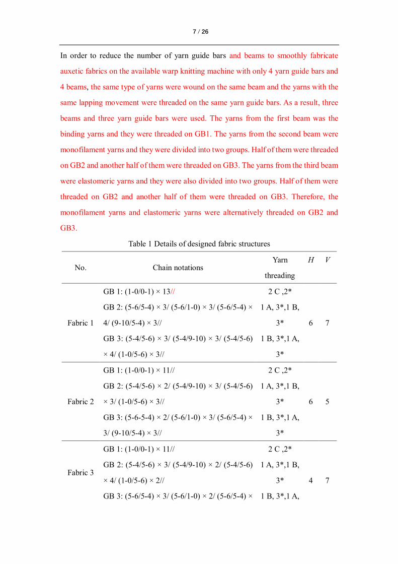
In order to reduce the number of yarn guide bars and beams to smoothly fabricate
auxetic fabrics on the available warp knitting machine with only 4 yarn guide bars and
4 beams, the same type of yarns were wound on the same beam and the yarns with the
same lapping movement were threaded on the same yarn guide bars. As a result, three
beams and three yarn guide bars were used. The yarns from the first beam was the
binding yarns and they were threaded on GB1. The yarns from the second beam were
monofilament yarns and they were divided into two groups. Half of them were threaded
on GB2 and another half of them were threaded on GB3. The yarns from the third beam
were elastomeric yarns and they were also divided into two groups. Half of them were
threaded on GB2 and another half of them were threaded on GB3. Therefore, the
monofilament yarns and elastomeric yarns were alternatively threaded on GB2 and
GB3.
Table 1 Details of designed fabric structures
No. Chain notations Yarn
threading
H V
Fabric 1
GB 1: (1-0/0-1) × 13// 2 C ,2*
6
7
GB 2: (5-6/5-4) × 3/ (5-6/1-0) × 3/ (5-6/5-4) ×
4/ (9-10/5-4) × 3//
1 A, 3*,1 B,
3*
GB 3: (5-4/5-6) × 3/ (5-4/9-10) × 3/ (5-4/5-6)
× 4/ (1-0/5-6) × 3//
1 B, 3*,1 A,
3*
Fabric 2
GB 1: (1-0/0-1) × 11// 2 C ,2*
6
5
GB 2: (5-4/5-6) × 2/ (5-4/9-10) × 3/ (5-4/5-6)
× 3/ (1-0/5-6) × 3//
1 A, 3*,1 B,
3*
GB 3: (5-6-5-4) × 2/ (5-6/1-0) × 3/ (5-6/5-4) ×
3/ (9-10/5-4) × 3//
1 B, 3*,1 A,
3*
Fabric 3
GB 1: (1-0/0-1) × 11// 2 C ,2*
4
7
GB 2: (5-4/5-6) × 3/ (5-4/9-10) × 2/ (5-4/5-6)
× 4/ (1-0/5-6) × 2//
1 A, 3*,1 B,
3*
GB 3: (5-6/5-4) × 3/ (5-6/1-0) × 2/ (5-6/5-4) × 1 B, 3*,1 A,
8 / 26
4/ (9-10/5-4) × 2// 3*
* represents unthreading of yarns. GB represents yarn guide bar. × means the
repeating times for the same chain notations within ‘()’. V and H represent knitting
courses for the vertical ribs and horizontal ribs respectively.
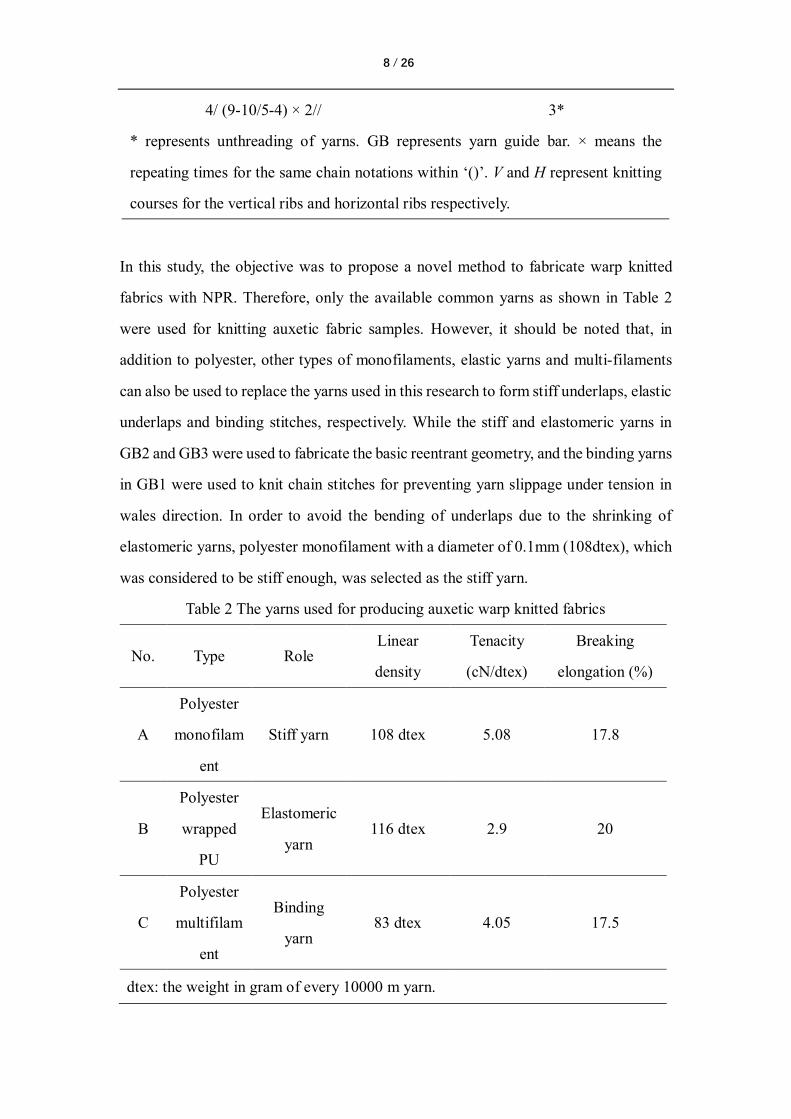
In this study, the objective was to propose a novel method to fabricate warp knitted
fabrics with NPR. Therefore, only the available common yarns as shown in Table 2
were used for knitting auxetic fabric samples. However, it should be noted that, in
addition to polyester, other types of monofilaments, elastic yarns and multi-filaments
can also be used to replace the yarns used in this research to form stiff underlaps, elastic
underlaps and binding stitches, respectively. While the stiff and elastomeric yarns in
GB2 and GB3 were used to fabricate the basic reentrant geometry, and the binding yarns
in GB1 were used to knit chain stitches for preventing yarn slippage under tension in
wales direction. In order to avoid the bending of underlaps due to the shrinking of
elastomeric yarns, polyester monofilament with a diameter of 0.1mm (108dtex), which
was considered to be stiff enough, was selected as the stiff yarn.
Table 2 The yarns used for producing auxetic warp knitted fabrics
No. Type Role Linear
density
Tenacity
(cN/dtex)
Breaking
elongation (%)
A
Polyester
monofilam
ent
Stiff yarn 108 dtex
5.08
17.8
B
Polyester
wrapped
PU
Elastomeric
yarn 116 dtex
2.9
20
C
Polyester
multifilam
ent
Binding
yarn 83 dtex
4.05
17.5
dtex: the weight in gram of every 10000 m yarn.
9 / 26
The machine used was a conventional high-speed tricot warp knitting machine. The
details of the machine are shown in Table 3. It should be pointed out that a multi-speed
electronic letting-off system is necessary for the tension control of warp yarns to help
the knitting process go smoothly. For all three fabrics, two-needle space tricot, six-
needle space tricot and chain stiches were knitted with let-off values of 1850, 3000 and
1500 mm/rack, respectively. To facilitate the analysis, all the fabrics were fabricated
with the same loop course density of 16 courses/cm. Although the speed of warp knitted
machine can reach 1100 rotations per minute (rpm), to fabricate the fabrics safely and
smoothly, the speed for fabricating the proposed fabrics was set as 800 rpm.
Table 3 Details of the machine used for producing auxetic warp knitted fabrics
Machine
type
Manufacturer Gauge Machine
width
(inch)
Let-off
system
Shogging
system
Speed
(rotations/mi
n)
HKS 4 Karl Mayer
(Germany)
28 42 Electronic
Electronic
800
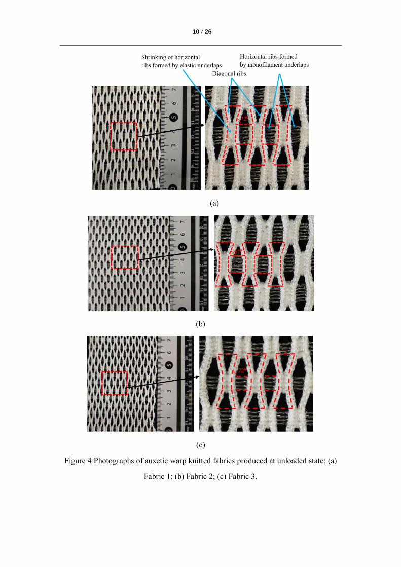
After knitting, all fabrics were subjected to a heat setting process under a temperature
of 160 0C for 5 minutes to stabilize the reentrant structure. The underlaps formed with
elastomeric yarns shrank due to their internal stress, and those formed with stiff yarns
kept straight due to their high stiffness. As a result, a reentrant hexagonal geometry was
formed in the fabrics. Figure 4 shows the fabrics obtained after finishing process. It can
be seen that the expected reentrant unit cell as designed were achieved and the angles
between the horizontal ribs and diagonal ribs are different due to the different diagonal
rib lengths in the fabrics.
10 / 26
(a)
(b)
(c)
Figure 4 Photographs of auxetic warp knitted fabrics produced at unloaded state: (a)
Fabric 1; (b) Fabric 2; (c) Fabric 3.
11 / 26
2.3 Tensile test
According to the previous studies [14, 26, 29, 32, 35], Poisson’s ratio values of fabrics
can be obtained through measuring both the lateral and longitudinal dimensional
changes of the samples. To facilitate the measurement of dimensional changes, marks
should be made at proper positions on the surface of the fabric samples and a better and
more effective method was to record the dimensional changes during the test by video.
After the test, the photos with marks were extracted from the video for measuring of
the lateral and longitudinal dimensional changes of the marks by screen ruler, through
which the Poisson’s ratio at a certain tensile strain can be calculated. It should be noted
that the lateral dimensional changes can be measured at any positions of the samples
along the tensile direction. However, the largest lateral dimensional changes are
obtained at the middle of the samples due to the constraint of clamps.
In this study, the tensile tests were conducted based on the method adopted in [26]. As
the designed reentrant geometry usually has in-plane auxetic effect in horizontal and
vertical direction as shown in Figure 1(b), the tensile tests were conducted in the wale
direction and the course direction and each test was conducted for three times. The size
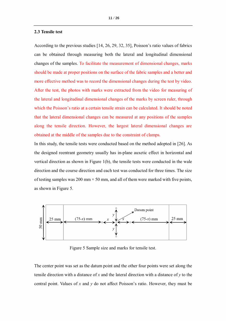
of testing samples was 200 mm × 50 mm, and all of them were marked with five points,
as shown in Figure 5.
Figure 5 Sample size and marks for tensile test.
The center point was set as the datum point and the other four points were set along the
tensile direction with a distance of x and the lateral direction with a distance of y to the
central point. Values of x and y do not affect Poisson’s ratio. However, they must be
12 / 26
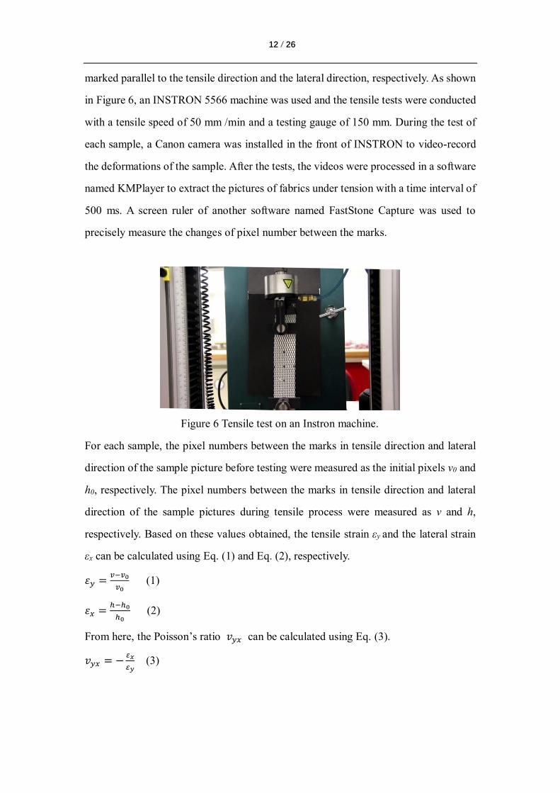
marked parallel to the tensile direction and the lateral direction, respectively. As shown
in Figure 6, an INSTRON 5566 machine was used and the tensile tests were conducted
with a tensile speed of 50 mm /min and a testing gauge of 150 mm. During the test of
each sample, a Canon camera was installed in the front of INSTRON to video-record
the deformations of the sample. After the tests, the videos were processed in a software
named KMPlayer to extract the pictures of fabrics under tension with a time interval of
500 ms. A screen ruler of another software named FastStone Capture was used to
precisely measure the changes of pixel number between the marks.
Figure 6 Tensile test on an Instron machine.
For each sample, the pixel numbers between the marks in tensile direction and lateral
direction of the sample picture before testing were measured as the initial pixels v0 and
h0, respectively. The pixel numbers between the marks in tensile direction and lateral
direction of the sample pictures during tensile process were measured as v and h,
respectively. Based on these values obtained, the tensile strain εy and the lateral strain
εx can be calculated using Eq. (1) and Eq. (2), respectively.
𝜀𝑦 =𝑣−𝑣0
𝑣0 (1)
𝜀𝑥 =ℎ−ℎ0
ℎ0 (2)
From here, the Poisson’s ratio 𝑣𝑦𝑥 can be calculated using Eq. (3).
𝑣𝑦𝑥 = −𝜀𝑥
𝜀𝑦 (3)
13 / 26
3. Results and discussion
3.1 Tensile behavior
Since all the three fabrics fabricated were produced based on the same geometry, their
auxetic behaviors should be similar. In this regard, one of the fabrics could be selected
as a representative fabric to analyze the typical auxetic behaviors of the auxetic warp
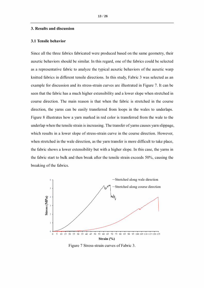
knitted fabrics in different tensile directions. In this study, Fabric 3 was selected as an
example for discussion and its stress-strain curves are illustrated in Figure 7. It can be
seen that the fabric has a much higher extensibility and a lower slope when stretched in
course direction. The main reason is that when the fabric is stretched in the course
direction, the yarns can be easily transferred from loops in the wales to underlaps.
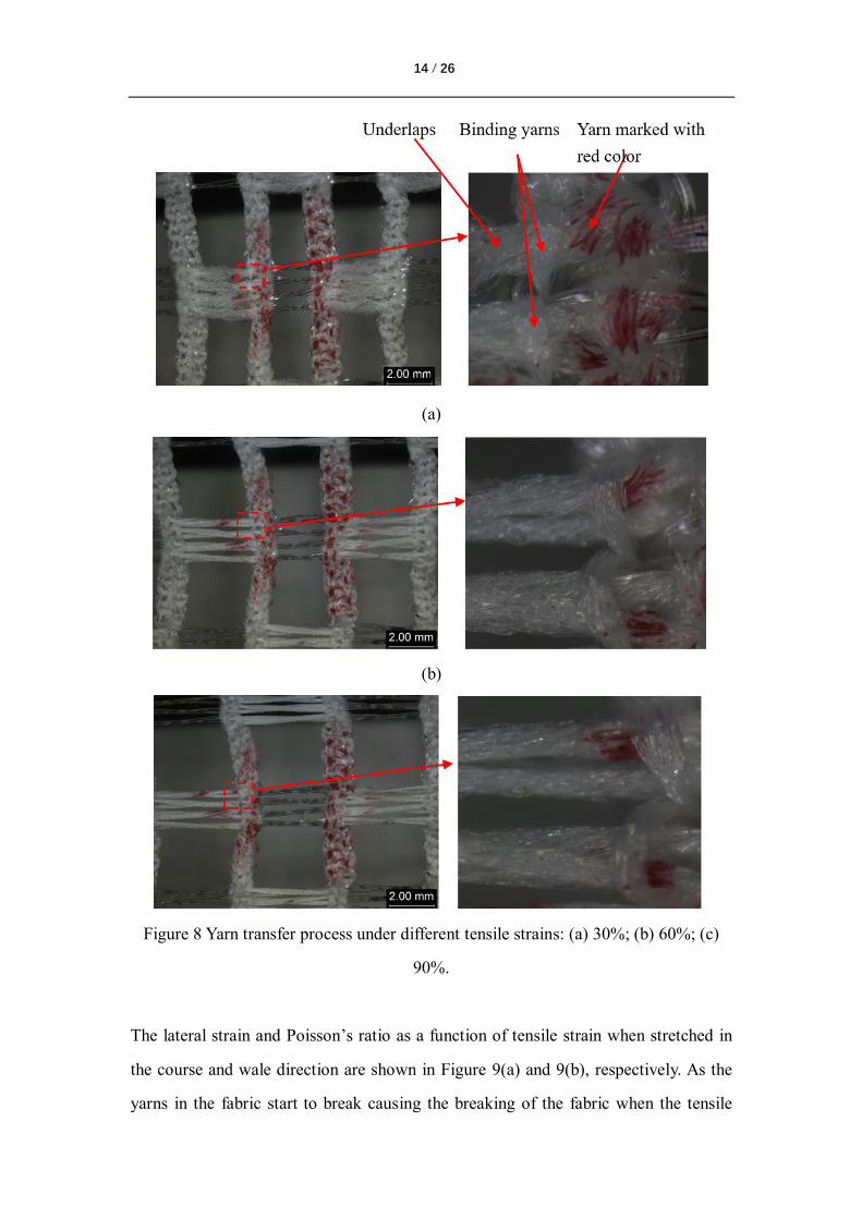
Figure 8 illustrates how a yarn marked in red color is transferred from the wale to the
underlap when the tensile strain is increasing. The transfer of yarns causes yarn slippage,
which results in a lower slope of stress-strain curve in the course direction. However,
when stretched in the wale direction, as the yarn transfer is more difficult to take place,
the fabric shows a lower extensibility but with a higher slope. In this case, the yarns in
the fabric start to bulk and then break after the tensile strain exceeds 50%, causing the
breaking of the fabrics.
Figure 7 Stress-strain curves of Fabric 3.
14 / 26
(a)
(b)
Figure 8 Yarn transfer process under different tensile strains: (a) 30%; (b) 60%; (c)
90%.
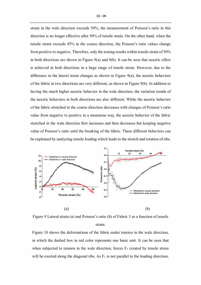
The lateral strain and Poisson’s ratio as a function of tensile strain when stretched in
the course and wale direction are shown in Figure 9(a) and 9(b), respectively. As the
yarns in the fabric start to break causing the breaking of the fabric when the tensile
15 / 26
strain in the wale direction exceeds 50%, the measurement of Poisson’s ratio in this
direction is no longer effective after 50% of tensile strain. On the other hand, when the
tensile strain exceeds 45% in the course direction, the Poisson’s ratio values change
from positive to negative. Therefore, only the testing results within tensile strain of 50%
in both directions are shown in Figure 9(a) and 9(b). It can be seen that auxetic effect
is achieved in both directions in a large range of tensile strain. However, due to the
difference in the lateral strain changes as shown in Figure 9(a), the auxetic behaviors
of the fabric in two directions are very different, as shown in Figure 9(b). In addition to
having the much higher auxetic behavior in the wale direction, the variation trends of
the auxetic behaviors in both directions are also different. While the auxetic behavior
of the fabric stretched in the course direction decreases with changes of Poisson’s ratio
value from negative to positive in a monotone way, the auxetic behavior of the fabric
stretched in the wale direction first increases and then decreases but keeping negative
value of Poisson’s ratio until the breaking of the fabric. These different behaviors can
be explained by analyzing tensile loading which leads to the stretch and rotation of ribs.
(a) (b)
Figure 9 Lateral strain (a) and Poisson’s ratio (b) of Fabric 3 as a function of tensile
strain.
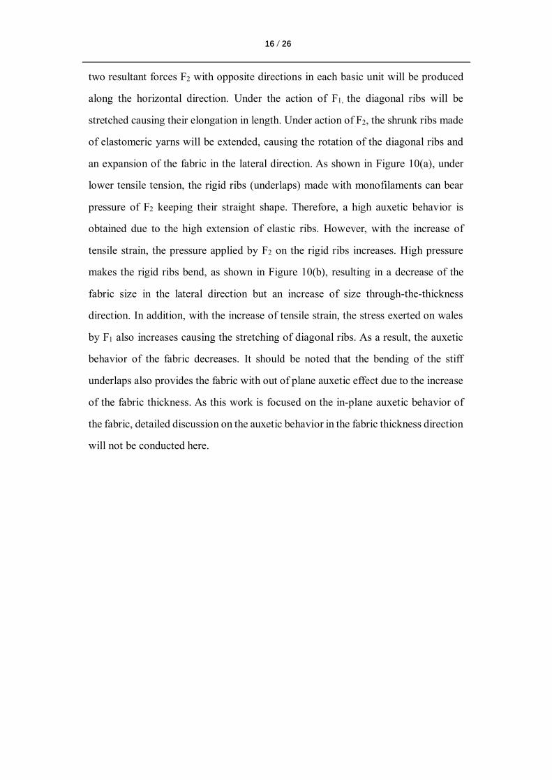
Figure 10 shows the deformations of the fabric under tension in the wale direction,
in which the dashed box in red color represents one basic unit. It can be seen that
when subjected to tension in the wale direction, forces F1 created by tensile stress
will be exerted along the diagonal ribs. As F1 is not parallel to the loading direction,
16 / 26
two resultant forces F2 with opposite directions in each basic unit will be produced
along the horizontal direction. Under the action of F1, the diagonal ribs will be
stretched causing their elongation in length. Under action of F2, the shrunk ribs made
of elastomeric yarns will be extended, causing the rotation of the diagonal ribs and
an expansion of the fabric in the lateral direction. As shown in Figure 10(a), under
lower tensile tension, the rigid ribs (underlaps) made with monofilaments can bear
pressure of F2 keeping their straight shape. Therefore, a high auxetic behavior is
obtained due to the high extension of elastic ribs. However, with the increase of
tensile strain, the pressure applied by F2 on the rigid ribs increases. High pressure
makes the rigid ribs bend, as shown in Figure 10(b), resulting in a decrease of the
fabric size in the lateral direction but an increase of size through-the-thickness
direction. In addition, with the increase of tensile strain, the stress exerted on wales
by F1 also increases causing the stretching of diagonal ribs. As a result, the auxetic
behavior of the fabric decreases. It should be noted that the bending of the stiff
underlaps also provides the fabric with out of plane auxetic effect due to the increase
of the fabric thickness. As this work is focused on the in-plane auxetic behavior of
the fabric, detailed discussion on the auxetic behavior in the fabric thickness direction
will not be conducted here.
17 / 26
(a) (b)
Figure 10 Fabric deformation when stretched in wale direction: (a) deformation at
strain below 5%; (b) deformation at strain of 40%.
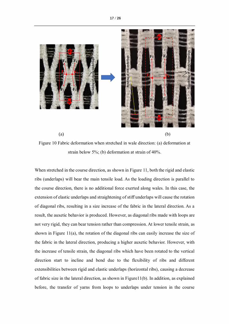
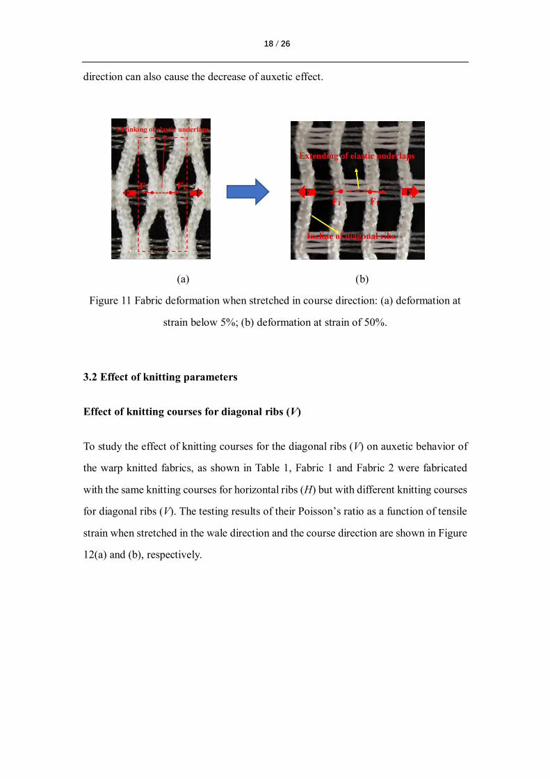
When stretched in the course direction, as shown in Figure 11, both the rigid and elastic
ribs (underlaps) will bear the main tensile load. As the loading direction is parallel to
the course direction, there is no additional force exerted along wales. In this case, the
extension of elastic underlaps and straightening of stiff underlaps will cause the rotation
of diagonal ribs, resulting in a size increase of the fabric in the lateral direction. As a
result, the auxetic behavior is produced. However, as diagonal ribs made with loops are
not very rigid, they can bear tension rather than compression. At lower tensile strain, as
shown in Figure 11(a), the rotation of the diagonal ribs can easily increase the size of
the fabric in the lateral direction, producing a higher auxetic behavior. However, with
the increase of tensile strain, the diagonal ribs which have been rotated to the vertical
direction start to incline and bend due to the flexibility of ribs and different
extensibilities between rigid and elastic underlaps (horizontal ribs), causing a decrease
of fabric size in the lateral direction, as shown in Figure11(b). In addition, as explained
before, the transfer of yarns from loops to underlaps under tension in the course
18 / 26
direction can also cause the decrease of auxetic effect.
(a) (b)
Figure 11 Fabric deformation when stretched in course direction: (a) deformation at
strain below 5%; (b) deformation at strain of 50%.
3.2 Effect of knitting parameters
Effect of knitting courses for diagonal ribs (V)
To study the effect of knitting courses for the diagonal ribs (V) on auxetic behavior of
the warp knitted fabrics, as shown in Table 1, Fabric 1 and Fabric 2 were fabricated
with the same knitting courses for horizontal ribs (H) but with different knitting courses
for diagonal ribs (V). The testing results of their Poisson’s ratio as a function of tensile
strain when stretched in the wale direction and the course direction are shown in Figure
12(a) and (b), respectively.
19 / 26
(a)
(b)
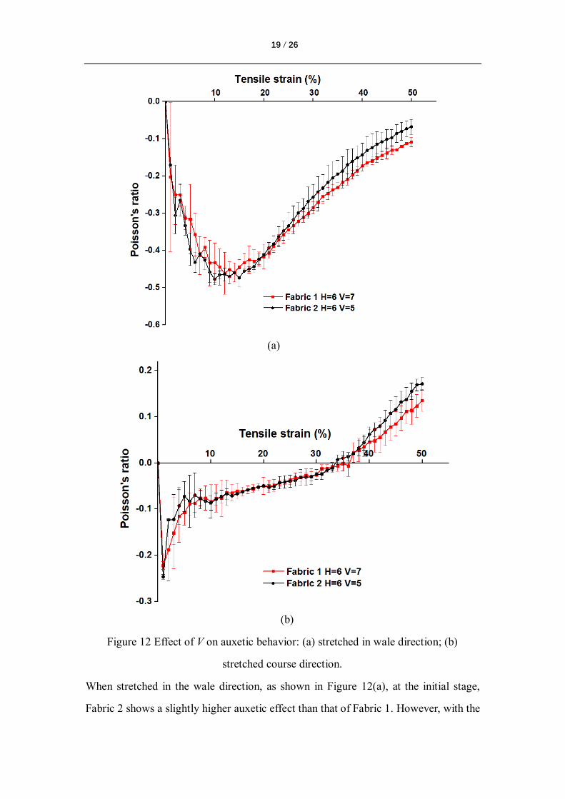
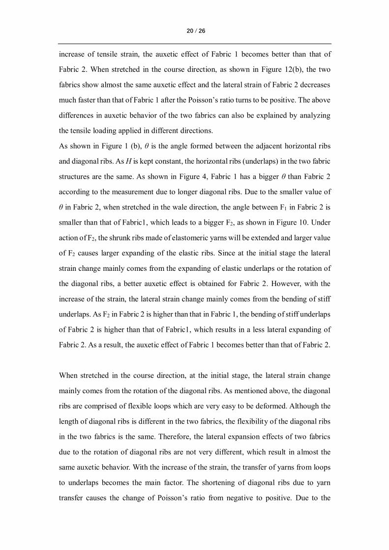
Figure 12 Effect of V on auxetic behavior: (a) stretched in wale direction; (b)
stretched course direction.
When stretched in the wale direction, as shown in Figure 12(a), at the initial stage,
Fabric 2 shows a slightly higher auxetic effect than that of Fabric 1. However, with the
20 / 26
increase of tensile strain, the auxetic effect of Fabric 1 becomes better than that of
Fabric 2. When stretched in the course direction, as shown in Figure 12(b), the two
fabrics show almost the same auxetic effect and the lateral strain of Fabric 2 decreases
much faster than that of Fabric 1 after the Poisson’s ratio turns to be positive. The above
differences in auxetic behavior of the two fabrics can also be explained by analyzing
the tensile loading applied in different directions.
As shown in Figure 1 (b), θ is the angle formed between the adjacent horizontal ribs
and diagonal ribs. As H is kept constant, the horizontal ribs (underlaps) in the two fabric
structures are the same. As shown in Figure 4, Fabric 1 has a bigger θ than Fabric 2
according to the measurement due to longer diagonal ribs. Due to the smaller value of
θ in Fabric 2, when stretched in the wale direction, the angle between F1 in Fabric 2 is
smaller than that of Fabric1, which leads to a bigger F2, as shown in Figure 10. Under
action of F2, the shrunk ribs made of elastomeric yarns will be extended and larger value
of F2 causes larger expanding of the elastic ribs. Since at the initial stage the lateral
strain change mainly comes from the expanding of elastic underlaps or the rotation of
the diagonal ribs, a better auxetic effect is obtained for Fabric 2. However, with the
increase of the strain, the lateral strain change mainly comes from the bending of stiff
underlaps. As F2 in Fabric 2 is higher than that in Fabric 1, the bending of stiff underlaps
of Fabric 2 is higher than that of Fabric1, which results in a less lateral expanding of
Fabric 2. As a result, the auxetic effect of Fabric 1 becomes better than that of Fabric 2.
When stretched in the course direction, at the initial stage, the lateral strain change
mainly comes from the rotation of the diagonal ribs. As mentioned above, the diagonal
ribs are comprised of flexible loops which are very easy to be deformed. Although the
length of diagonal ribs is different in the two fabrics, the flexibility of the diagonal ribs
in the two fabrics is the same. Therefore, the lateral expansion effects of two fabrics
due to the rotation of diagonal ribs are not very different, which result in almost the
same auxetic behavior. With the increase of the strain, the transfer of yarns from loops
to underlaps becomes the main factor. The shortening of diagonal ribs due to yarn
transfer causes the change of Poisson’s ratio from negative to positive. Due to the
21 / 26
smaller value of V of Fabric 2, the shortening effect of diagonal ribs in Fabric 2 becomes
more important than in Fabric 1, which results in higher positive Poisson’s ratio of
Fabric 2.
3.3 Effect of knitting courses for horizontal ribs (H)
To study the effect of the knitting courses for horizontal ribs on auxetic effect, Fabric 1
and Fabric 3 were fabricated with the same knitting courses for diagonal ribs (V) but
with the different knitting courses for horizontal ribs (H), as shown in Table 1. The test
results of the two fabrics in the wale and course direction are shown in Figure 13 (a)
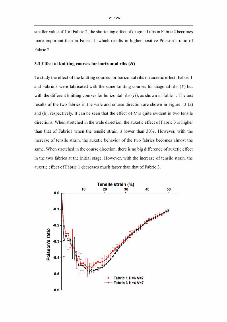
and (b), respectively. It can be seen that the effect of H is quite evident in two tensile
directions. When stretched in the wale direction, the auxetic effect of Fabric 3 is higher
than that of Fabric1 when the tensile strain is lower than 30%. However, with the
increase of tensile strain, the auxetic behavior of the two fabrics becomes almost the
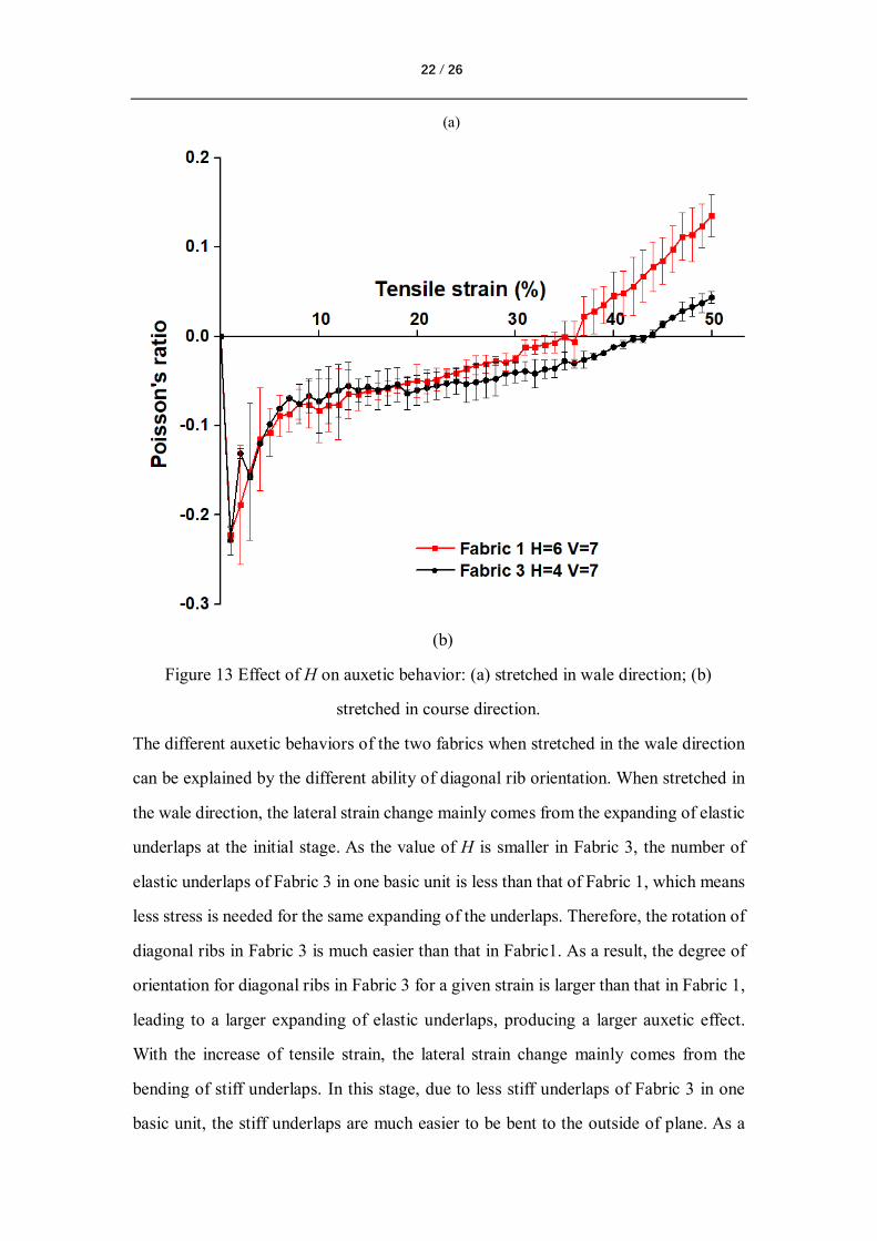
same. When stretched in the course direction, there is no big difference of auxetic effect
in the two fabrics at the initial stage. However, with the increase of tensile strain, the
auxetic effect of Fabric 1 decreases much faster than that of Fabric 3.
22 / 26
(a)
(b)
Figure 13 Effect of H on auxetic behavior: (a) stretched in wale direction; (b)
stretched in course direction.
The different auxetic behaviors of the two fabrics when stretched in the wale direction
can be explained by the different ability of diagonal rib orientation. When stretched in
the wale direction, the lateral strain change mainly comes from the expanding of elastic
underlaps at the initial stage. As the value of H is smaller in Fabric 3, the number of
elastic underlaps of Fabric 3 in one basic unit is less than that of Fabric 1, which means
less stress is needed for the same expanding of the underlaps. Therefore, the rotation of
diagonal ribs in Fabric 3 is much easier than that in Fabric1. As a result, the degree of
orientation for diagonal ribs in Fabric 3 for a given strain is larger than that in Fabric 1,
leading to a larger expanding of elastic underlaps, producing a larger auxetic effect.
With the increase of tensile strain, the lateral strain change mainly comes from the
bending of stiff underlaps. In this stage, due to less stiff underlaps of Fabric 3 in one
basic unit, the stiff underlaps are much easier to be bent to the outside of plane. As a
23 / 26
result, the lateral strain of Fabric 3 decreases much faster than that of Fabric 1. However,
with the further increase of tensile strain, the orientation degree of the diagonal ribs in
the two fabrics tends to be almost the same. Therefore, two fabrics demonstrate almost
the same auxetic behavior after the tensile strain exceeds 30%.
When stretched in the course direction, the difference of auxetic behavior may come
from the transfer of yarns from loops to underlaps. As there are more underlaps within
a unit cell in Fabric 1 than that of Fabric 3, more loops in Fabric 1 will shrink for a
given tensile strain, leading to higher shrinkage in the lateral direction. As a result, the
auxetic behavior of Fabric 1 decreases much faster than that of Fabric 3, with faster
change of Poisson’s ratio value from negative to positive.
Conclusions
A novel type of auxetic warp knitted structure was first designed based on the
modification of a non-auxetic geometry to a reentrant auxetic structure. Various auxetic
fabrics were then fabricated using a conventional warp knitting machine with different
knitting parameters. The fabric samples obtained were finally tested to assess their
auxetic behavior. Based on the test results, the following conclusions can be obtained.
1. Auxetic warp knitted structures can be achieved using elastomeric yarns and stiff
yarns in a special arrangement on a warp knitting machine with more than three
yarn guide bars. This technique not only enlarges the method of knitting auxetic
fabrics using warp knitting technology, but also make it possible to manufacture
auxetic fabrics using conventional machines with conventional yarns.
2. The use of binding yarn is necessary to fabricate auxetic warp knitted fabrics with
stable structure. Binding yarns should be used in the front bar to get the binding
effect.
3. The auxetic knitted fabrics have obvious auxetic behavior in both wale and course
directions. When stretched in the wales direction, the fabrics can keep auxetic effect
till breaking. However, when stretched in the course direction, the Poisson’s ratio
24 / 26
can change from negative to positive when the tensile strain exceeds some limited
values.
4. The knitting courses for the diagonal ribs and horizontal ribs (underlaps) in a unit
cell have obvious effect on the auxetic behavior.
As this work is only a primary study, some limitations still exist. For example, the
geometrical model used to study the relationships between the parameters and
Poisson’s ratio of the structures has not been set up and the auxetic behaviors in off-
axis directions are not clear. Besides, the stability of the auxetic effect has not been
tested. Therefore, future work will be focused on the establishment of geometrical
models, the test of the fabrics in off-axis directions, and the study of auxetic stability.
Finally, as the objective of this paper is to propose a novel method to fabricate auxetic
warp knitted fabrics, only the available polyester yarns were used in this study. The
comparison of using different types of yarns to realize the same warp knitted structure
can also be another future research direction.
Acknowledgments
The authors would like to thank the funding support from the Research Grants Council
of Hong Kong Special Administrative Region Government (grant number: 15209616)
and The Hong Kong Polytechnic (internal project reference: YBUZ). The authors
would also like to thank the Engineering Research Center for Knitting Technology of
Jiangnan University to provide their warp knitting machine for producing the fabric
samples.
References
1. Ma, P., et al., Review on the knitted structures with auxetic effect. The Journal of The Textile
Institute, 2017. 108(6): p. 947-961.
2. Evans, K.E. and A. Alderson, Auxetic materials: functional materials and structures from
lateral thinking! Advanced materials, 2000. 12(9): p. 617-628.
3. Lim, T.-C., Auxetic materials and structures. 2015: Springer.
4. Lakes, R., Foam structures with a negative Poisson's ratio. Science, 1987. 235: p. 1038-
1041.
5. Hu, H. and A. Zulifqar, Auxetic textile materials-A review. J Textile Eng Fashion Technol,
25 / 26
2016. 1(1): p. 00002.
6. Grima, J.N., et al., On the auxetic properties of rotating rhombi and parallelograms: a
preliminary investigation. physica status solidi (b), 2008. 245(3): p. 521-529.
7. Liu, Y. and H. Hu, A review on auxetic structures and polymeric materials. Scientific
Research and Essays, 2010. 5(10): p. 1052-1063.
8. Scarpa, F. and P. Tomlin, On the transverse shear modulus of negative Poisson’s ratio
honeycomb structures. Fatigue & Fracture of Engineering Materials & Structures, 2000.
23(8): p. 717-720.
9. Lakes, R. and K. Elms, Indentability of conventional and negative Poisson's ratio foams.
Journal of Composite Materials, 1993. 27(12): p. 1193-1202.
10. Alderson, K., et al., An experimental study of ultrasonic attenuation in microporous
polyethylene. Applied Acoustics, 1997. 50(1): p. 23-33.
11. Wang, Z. and H. Hu, Tensile and forming properties of auxetic warp-knitted spacer fabrics.
Textile Research Journal, 2017. 87(16): p. 1925-1937.
12. Evans, K., The design of doubly curved sandwich panels with honeycomb cores.
Composite Structures, 1991. 17(2): p. 95-111.
13. Rajapakse, Y. and Y. Miyano, MECHANICAL PROPERTIES OF AN AUXETIC POLYURETHANE
FOAM COMPOSITE. Cellular Polymers, 1989. 8(5): p. 343-359.
14. Wang, Z. and H. Hu, 3 D auxetic warp‐knitted spacer fabrics. physica status solidi (b), 2014.
251(2): p. 281-288.
15. Sanami, M., et al., Auxetic materials for sports applications. Procedia Engineering, 2014.
72: p. 453-458.
16. Wang, Z. and H. Hu, Auxetic materials and their potential applications in textiles. Textile
research journal, 2014. 84(15): p. 1600-1611.
17. Saxena, K.K., R. Das, and E.P. Calius, Three decades of auxetics research− materials with
negative Poisson's ratio: a review. Advanced Engineering Materials, 2016. 18(11): p. 1847-
1870.
18. Lakes, R.S., Negative-Poisson's-ratio materials: auxetic solids. Annual review of materials
research, 2017. 47.
19. Jiang, J.-W., S.Y. Kim, and H.S. Park, Auxetic nanomaterials: Recent progress and future
development. Applied Physics Reviews, 2016. 3(4): p. 041101.
20. Park, H.S. and S.Y. Kim, A perspective on auxetic nanomaterials. Nano Convergence, 2017.
4(1): p. 10.
21. Lim, T.C., Analogies across auxetic models based on deformation mechanism. physica
status solidi (RRL)–Rapid Research Letters, 2017. 11(6): p. 1600440.
22. Miller, W., et al., The manufacture and characterisation of a novel, low modulus, negative
Poisson’s ratio composite. Composites Science and Technology, 2009. 69(5): p. 651-655.
23. Wright, J.R., et al., On the design and characterisation of low-stiffness auxetic yarns and
fabrics. Textile Research Journal, 2012. 82(7): p. 645-654.
24. Ng, W.S. and H. Hu, Woven fabrics made of auxetic plied yarns. Polymers, 2018. 10(2): p.
226.
25. Zulifqar, A. and H. Hu, Development of bi‐stretch auxetic woven fabrics based on re‐
entrant hexagonal geometry. physica status solidi (b), 2019. 256(1): p. 1800172.
26 / 26
26. Zulifqar, A., T. Hua, and H. Hu, Development of uni-stretch woven fabrics with zero and
negative Poisson’s ratio. Textile Research Journal, 2017.
27. Cao, H., et al., Bi-stretch auxetic woven fabrics based on foldable geometry. Textile
Research Journal, 2018: p. 0040517518798646.
28. Liu, Y., et al., Negative Poisson’s ratio weft-knitted fabrics. Textile Research Journal, 2010.
80(9): p. 856-863.
29. Hu, H., Z. Wang, and S. Liu, Development of auxetic fabrics using flat knitting technology.
Textile research journal, 2011. 81(14): p. 1493-1502.
30. Ugbolue, S.C., et al., The formation and performance of auxetic textiles. Part I: theoretical
and technical considerations. Journal of The Textile Institute, 2010. 101(7): p. 660-667.
31. Ugbolue, S.C., et al., The formation and performance of auxetic textiles. Part II: geometry
and structural properties. Journal of The Textile Institute, 2011. 102(5): p. 424-433.
32. Alderson, K., et al., Auxetic warp knit textile structures. physica status solidi (b), 2012.
249(7): p. 1322-1329.
33. Ma, P., Y. Chang, and G. Jiang, Design and fabrication of auxetic warp-knitted structures
with a rotational hexagonal loop. Textile Research Journal, 2016. 86(20): p. 2151-2157.
34. Chang, Y. and P. Ma, Fabrication and property of auxetic warp-knitted spacer structures
with mesh. Textile Research Journal, 2017: p. 0040517517716910.
35. Glazzard, M. and P. Breedon, Weft‐knitted auxetic textile design. physica status solidi (b),
2014. 251(2): p. 267-272.