Embed Size (px)
Citation preview

DOT/FAA/AR-10/2 Air Traffic Organization NextGen & Operations Planning Office of Research and Technology Development Washington, DC 20591
Development of an Improved Fire Test Method and Criteria for Aircraft Electrical Wiring John W. Reinhardt April 2010 Final Report This document is available to the U.S. public through the National Technical Information Service (NTIS), Springfield, Virginia 22161. This document is also available from the Federal Aviation Administration William J. Hughes Technical Center at actlibrary.tc.faa.gov.
U.S. Department of Transportation Federal Aviation Administration

NOTICE This document is disseminated under the sponsorship of the U.S. Department of Transportation in the interest of information exchange. The United States Government assumes no liability for the contents or use thereof. The United States Government does not endorse products or manufacturers. Trade or manufacturer’s names appear herein solely because they are considered essential to the objective of this report. This document does not constitute FAA certification policy. Consult your local FAA aircraft certification office as to its use. This report is available at the Federal Aviation Administration William J. Hughes Technical Center’s Full-Text Technical Reports page: actlibrary.tc.faa.gov in Adobe Acrobat portable document format (PDF).

Technical Report Documentation Page 1. Report No.
DOT/FAA/AR-10/2
2. Government Accession No. 3. Recipient's Catalog No.
4. Title and Subtitle
DEVELOPMENT OF AN IMPROVED FIRE TEST METHOD AND CRITERIA FOR AIRCRAFT ELECTRICAL WIRING
5. Report Date
April 2010
6. Performing Organization Code
7. Author(s)
John W. Reinhardt
8. Performing Organization Report No.
9. Performing Organization Name and Address
Federal Aviation Administration
10. Work Unit No. (TRAIS)
William J. Hughes Technical Center Airport and Aircraft Safety Group Atlantic City International Airport, NJ 08405
11. Contract or Grant No.
12. Sponsoring Agency Name and Address
U.S. Department of Transportation Federal Aviation Administration Air Traffic Organization NextGen & Operations Planning Office of Research and Technology Development
13. Type of Report and Period Covered
Final Report
Washington, DC 20591 14. Sponsoring Agency Code ANM-100
15. Supplementary Notes
16. Abstract
The Federal Aviation Administration (FAA), as part of its hidden in-flight fire mitigation program, developed an improved flammability test method for aircraft electrical wiring insulation materials (including jackets and other wire protective materials). A comprehensive fire test research and development (R&D) project was conducted on aircraft electrical wiring insulation materials in an effort to continue mitigating the threat of in-flight fires. Previous work at the FAA and the National Fire Protection Association have indicated that the current FAA-required 60-degree Bunsen burner test for electric wire was inadequate to qualify wire when bundled and subjected to a severe ignition source. A literature search and in-house fire tests were conducted during this effort. The results of the literature search indicated that there was no small-scale flammability test standard available that considered radiant heat and wire bundling in its specifications or acceptance criteria that included burn length and after-flame extinguishing time; therefore, an improved flammability test standard for aircraft wiring was required. In-house fire tests were conducted to develop an improved flammability test and provide support data; tests included the current FAA-required 60-degree Bunsen burner test, the microscale combustion calorimetry test (ASTM D 7309-07), the thermogravimetric analysis (ASTM E 2550-07), the intermediate-scale fire test, and the radiant heat panel test. From this R&D effort, an alternative radiant heat panel test method was developed. This method was effective in evaluating the in-flight fire resistance qualities of aircraft electrical wiring insulation. 17. Key Words
Aircraft wiring, Flammability tests, Radiant heat, Fire propagation, Wire bundles, Microscale combustion calorimetry, Thermogravimetric analysis, Intermediate-scale fire test, Radiant heat panel tests
18. Distribution Statement
This document is available to the U.S. public through the National Technical Information Service (NTIS), Springfield, Virginia 22161. This document is also available from the Federal Aviation Administration William J. Hughes Technical Center at actlibrary.tc.faa.gov.
19. Security Classif. (of this report) Unclassified
20. Security Classif. (of this page) Unclassified
21. No. of Pages 95
22. Price
Form DOT F 1700.7 (8-72) Reproduction of completed page authorized

ACKNOWLEDGEMENTS
The author would like acknowledge the participating members of the International Aircraft Materials Fire Test Working Group who greatly contributed to the success of this project. He would like to thank his task group members for their input, challenges, and sharing of lessons learned. The author is also appreciative of the engineering and scientific consultations provided by Patricia Cahill, Dr. Rich Lyon, Dr. Stanislav I. Stoliarov, Rich Walters, and Natallia Safronava. The author is thankful for the technical and administrative support provided by Rick Whedbee, Frank Gibbons, Mark Materio, Brian Conover, Matt Dutton, and Leroy Dickerson.
iii/iv

TABLE OF CONTENTS Page EXECUTIVE SUMMARY xi 1. INTRODUCTION 1
1.1 Purpose 1 1.2 Background 1 1.3 Scope 2
2. TECHNICAL APPROACH 2
2.1 Test Method Selection 2 2.1.1 Test Method Descriptions 6
2.2 Material Selection 16
2.2.1 The CAT 3 Cable 21 2.2.2 CAT 5e Cable 21 2.2.3 Computer Cable 21 2.2.4 M17/28-RG58 Cable 21 2.2.5 Neoprene Lead Wire 21 2.2.6 Fiber-Optic Riser Cable 22 2.2.7 Hypalon Lead Wire 22 2.2.8 MS5086/1 Lead Wire 22 2.2.9 MS22759/14 Lead Wire 22 2.2.10 BMS13-48-1 Lead Wire 22 2.2.11 BMS13-60 Lead Wire 22 2.2.12 MS22759/16 Lead Wire 23 2.2.13 MS22759/32 Lead Wire 23 2.2.14 MS81044/6 Lead Wire 23 2.2.15 MS81381/21 Lead Wire 23 2.2.16 BMS13-72 Cable 23 2.2.17 MS22759/11 Lead Wire 23 2.2.18 MS22759/33 Lead Wire 23 2.2.19 MS22759/5 Lead Wire 24 2.2.20 Silicone 200 Lead Wire 24 2.2.21 BMS13-55 Lead Wire 24 2.2.22 MS22759/86 Lead Wire 24 2.2.23 Wire Protective Materials 24
2.3 Analysis 24
v

3. RESULTS 25
3.1 The FAA 60-Degree Bunsen Burner Test for Electrical Wire 25 3.2 Microscale Combustion Calorimetry (ASTM D 7309-07) 28 3.3 Thermogravimetric Analysis 33 3.4 Intermediate-Scale Fire Test 34 3.5 Radiant Heat Panel Test 45
3.5.1 Procedure 1 45 3.5.2 Procedure 2 46 3.5.3 Procedure 3 47 3.5.4 Procedure 4 48 3.5.5 Procedure 5 50 3.5.6 Procedure 6 52 3.5.7 Procedure 7 54 3.5.8 Procedure 8 54 3.5.9 Procedure 9 56 3.5.10 Procedure 10 58
3.6 Improved 30-Degree RHP Test Verification 63
4. RESULTS AND CONCLUSIONS 65 5. REFERENCES 66 APPENDIX A—FLAMMABILITY TEST METHOD AND CRITERIA FOR AIRCRAFT ELECTRICAL WIRING
vi

LIST OF FIGURES
Figure Page 1 The 60-Degree Bunsen Burner Test Setup for Electric Wires 4 2 Radiant Heat Panel Test Apparatus 4 3 Microscale Combustion Calorimetry Test Equipment 5 4 Intermediate-Scale Fire Test Fixture (Wide View) 5 5 Intermediate-Scale Fire Test Setup 8 6 Thermocouples Characterization Fixture Inside RHP Apparatus 10 7 Calorimeter Characterization Fixture Inside RHP Apparatus 11 8 The RHP Temperature History With Thermocouples 19 cm From RHP 11 9 The RHP Heat Flux History With Calorimeters 19 cm From RHP 12 10 The RHP Temperature History With Thermocouples 7.63 cm From RHP 12 11 Wire Mounted on the Sample Holder at a 30-Degree Angle 13 12 Wire Mounted on the Sample Holder at a 0-Degree Angle (Horizontal) 14 13 Short Wire Mounted on the Sample Holder Using Alligator Clips 15 14 Short Wire Held With Alligator Clips 15 15 Wire and Cable Specimens 19 16 Current Aviation-Grade Wire and Cable Specimens 20 17 The 60-Degree Bunsen Burner Test Results 27 18 Typical MSCC Flammability Characteristics 28 19 The MSCC Test Results: Onset Temperature Versus Specific Heat of
Combustion of the Gas 31 20 Aircraft Wire Insulation Flammability Characteristics Box 32 21 Typical TG and DTG Curves 34
vii

22 Intermediate-Scale Fire Test Apparatus 35 23 Intermediate-Scale Fire Test Baseline Temperature 39 24 Intermediate-Scale Fire Test Baseline Heat Flux 39 25 Average ISF Test Baseline Temperature (Threat) Versus Wires and Cables Onset
Temperature Range 40 26 Intermediate-Scale Fire Test of Wires and Cables (Plot 1): Thermocouple 4 41 27 Intermediate-Scale Fire Test of Wires and Cables (Plot 2): Thermocouple 4 41 28 Intermediate-Scale Fire Test of Wires and Cables (Plot 3): Thermocouple 4 42 29 Intermediate-Scale Fire Test of Wires and Cables (Plot 4): Thermocouple 4 42 30 Intermediate-Scale Fire Test Results: Maximum Flame-Extinguishing Time Versus
Maximum Burn Length 43 31 Post-ISF Test of Current Aviation-Grade Wires and Cables 44 32 Post-ISF Test of Other Wires and Cables 45 33 Radiant Heat Panel Test Results Using Procedure 2 47 34 Radiant Heat Panel Test Results Using Procedure 3 48 35 Radiant Heat Panel Test Results Using Procedure 4 49 36 Radiant Heat Panel Test Results Using Procedure 5 51 37 Radiant Heat Panel Test Results Using Procedure 6 53 38 Radiant Heat Panel Test Results Using Procedure 8 55 39 Radiant Heat Panel Test Results Using Procedure 9 57 40 The 30-Degree RHP Test Bundled-Wire Holder, Procedure 10 58 41 Radiant Heat Panel Tests Results of Bundled Wires and Cables Using
Procedure 10 60 42 Posttest Fire-Worthy Insulation Specimens (Bundled) 61 43 Posttest Non-Fire-Worthy Insulation and Jacket Material Specimens (Bundled) 61 44 Wire Bundle Sleeves (Pretest and Posttest) 63
viii

LIST OF TABLES
Table Page 1 Radiant Heat Panel Test Procedures Summary 9 2 Wires and Cables Specifications 17 3 Average Results of the Wire and Cable Bunsen Burner Tests 26 4 Average Results of the MSCC Test of Wires and Cables 29 5 Thermogravimetric Analysis Test Data 33 6 Intermediate-Scale Fire Test of Wires and Cables: Peak Temperature 36 7 Intermediate-Scale Fire Test of Wires and Cables: Peak Heat Flux 36 8 Intermediate-Scale Fire Test Results: Flammability Data 37 9 Average Results of the RHP Test of Wires and Cables, Procedure 2 46 10 Average Results of the RHP Test of Wires and Cables, Procedure 3 47 11 Average Results of the RHP Test of Wires and Cables, Procedure 4 48 12 Average Results of the RHP Test of Wires and Cables, Procedure 5 50 13 Average Results of the RHP Test of Wires and Cables, Procedure 6 52 14 Average Results of the RHP Test of Wires and Cables, Procedure 8 54 15 Average Results of the RHP Test of Wires and Cables, Procedure 9 56 16 Average Results of the RHP Test of Bundled Wires and Cables, Procedure 10 59 17 Average Results of the RHP Test of Wire Bundle Sleeves Using Procedure 10 62 18 Acceptance Comparison Between Test Methods 64
ix

x
LIST OF ACRONYMS
ABL Average burn length AC Advisory Circular AFET Average flame-extinguishing time AWG American Wire Gauge CFR Code of Federal Regulations DTG First derivative of the mass-temperature curve ETFE Ethylene-tetrafluoroethylene FAA Federal Aviation Administration FEP Fluorinated ethylene propylene FORC Fiber-optic riser cable FR Fire retardant HVAC Heating, ventilation, and air conditioning ISF Intermediate-scale fire ML Mass loss MSCC Microscale combustion calorimetry NFPA National Fire Protection Association PCF Pounds per cubic foot PE Polyethylene PEEK Polyetheretherketone PI Polyimide PPS Polyphenylene sulfide PTFE Polytetrafluoroethylene PVC Polyvinylchloride PVDF Polyvinylidene fluoride RHP Radiant heat panel SAE Society of Automotive Engineers TFE Tetrafluoroethylene TG Thermogravimetric TGA Thermogravimetric analysis

EXECUTIVE SUMMARY
The Federal Aviation Administration (FAA), in conjunction with the International Aircraft Materials Fire Test Working Group, as part of its hidden in-flight fire mitigation program, developed an improved flammability test method for aircraft electrical wiring insulation materials (including jackets and other wire protective materials). It confirmed earlier findings that the current FAA-required 60-degree (single-wire) Bunsen burner flammability test (Bunsen burner test) was inadequate to gauge the behavior of electrical wiring subjected to a robust fire under realistic test conditions. The technical approach used to develop this new aircraft electric wire flammability test method was similar to the approach used during the recent development of improved thermal acoustic insulation and aircraft heating, ventilation, and air-conditioning (HVAC) ducting material fire test methods. Basically, fire tests were conducted to establish a baseline to determine the combustion and flammability properties of the wiring insulation materials and to develop an improved small-scale flammability test that correlated with the results of realistic, intermediate-scale fire tests, which subjected wire specimens to a robust fire source. An extensive literature search showed that an improved small-scale flammability test standard, using radiant heat and wire and cable bundling, was needed. The in-house fire tests included the following test methods: (1) the Bunsen burner test, (2) ASTM D 7309-07 microscale combustion calorimetry (MSCC), (3) ASTM E 2550-07 thermogravimetric analysis (TGA), (4) the intermediate-scale fire (ISF) test, and (5) the radiant heat panel (RHP) test. The Bunsen burner test results (baseline) demonstrated that 20 of the 22 selected wire specimens passed this certification test, although it was subsequently determined that 7 of the wires originally found to be acceptable were non-fire-worthy. The flammability characteristics and thermal stability of the selected wire specimens were determined with the MSCC and TGA tests. Combustion properties, such as decomposition temperature, onset temperature, combustion temperature, specific heat of combustion, and heat release capacity, were measured. The MSCC and TGA test results showed that aviation-grade wire had very desirable combustion properties when compared to the non-aviation-grade specimens. The ISF test was used to expose the selected bundled-wire specimens to a realistic aircraft cabin attic fire and to determine their flammability performance. Burn length, after-flame extinguishing time, mass loss, temperature, and heat flux were recorded during this test. Results showed that all aviation-grade wires experienced shorter burn lengths, shorter after-flame extinguishing times, less mass loss, lower temperatures, and less heat fluxes when compared to the other wire specimens. These results were used to establish the fire worthiness of the aircraft wire in terms of pass/fail criteria. Since the 60-degree Bunsen burner flammability test did not match these results, the goal was to develop an improved test method that rated materials in a manner that correlated with ISF test results in terms of pass/fail criteria. Current aircraft-grade wires passed the ISF test. The ASTM E 648 test method, adapted by the FAA for thermal acoustic insulation certification, was selected because it had an adjustable RHP, a propane pilot burner, and other parameters that could be varied to determine the impact of test results on the agreement with ISF test data. After ten procedural iterations, to establish the proper equipment settings and test procedure, a test method was developed that matched the results of the ISF test data.
xi
xii
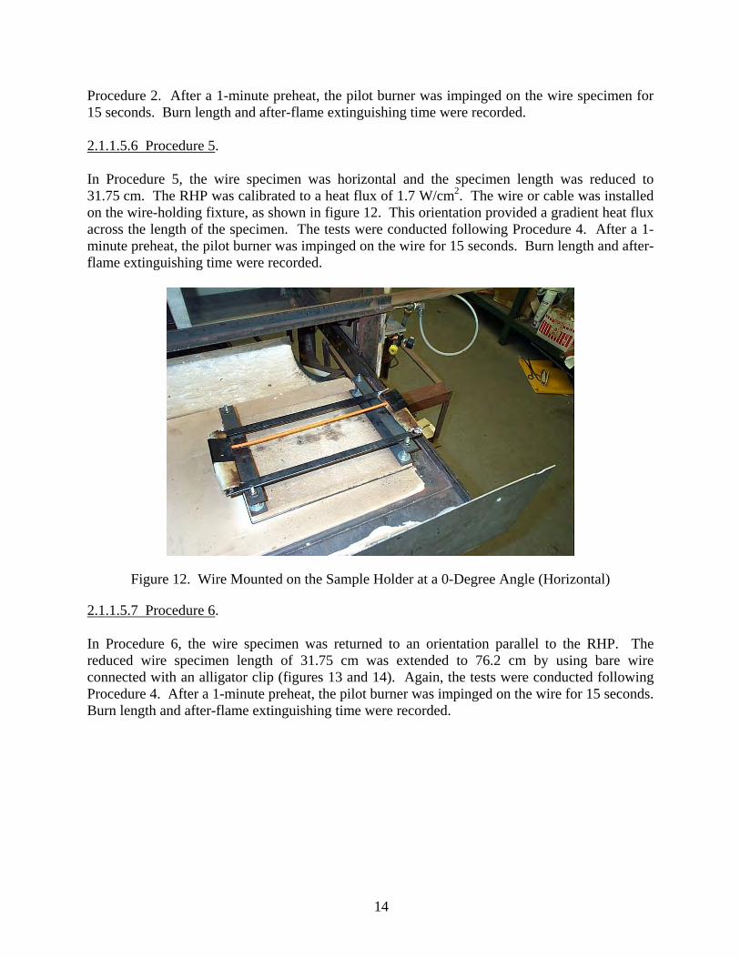
Briefly, the fire exposure conditions in the improved test method consisted of a 1.7-W/cm2 RHP heat flux and a pilot burner adjusted to have a 19-mm flame length. After the equipment was calibrated, the 38.1-cm-long bundled-wire (~1.27-cm-diameter) specimen was mounted on a 30-degree angle fixture and was placed inside the RHP apparatus. The specimen was preheated with radiant heat for 1 minute and then impinged with the propane pilot burner for 3 seconds. To pass the acceptance criteria, the burn length must be less than 7.62 cm (3 inches), and the after-flame extinguishing time must be less than 30 seconds. This improved test method was also used to test cable bundle protective sleeves. Of the ten sleeves tested, six passed the test, but the others burned significantly. This proposed test method for aircraft electrical wire uses existing FAA certification test equipment, produces consistent and repeatable test results, and correlates well with the ISF test results when compared to the currently used FAA 60-degree Bunsen burner flammability test.

1. INTRODUCTION.
1.1 PURPOSE.
The purpose of this report is to describe the development of an improved test method to determine the flammability of aircraft electrical wires, cables, and other wire protective materials. This report also includes a description of the improved flammability test method in a standard Federal Aviation Administration (FAA) format. 1.2 BACKGROUND.
This activity was part of an FAA program to examine the adequacy of the current FAA-required 60-degree Bunsen burner flammability test (hereinafter referred to as the Bunsen burner test) requirements for predominant cabin materials in hidden areas of large transport aircraft that may impact in-flight fire safety. The driving force behind this activity was a number of in-flight fire incidents and accidents that initiated in the inaccessible hidden areas of the cabin and cockpit. The selected materials included thermal acoustic insulation, heating, ventilation, and air-conditioning (HVAC) ducting, and electrical wiring insulation and jackets. Large- and intermediate-scale evaluation test results showed that the Bunsen burner test methods did not predict the behavior of some of the hidden materials when they were subjected to a robust fire. Because of these results, the FAA developed improved flammability test methods for thermal acoustic insulation and aircraft HVAC ducting materials, which are documented in Title 14 Code of Federal Regulations (CFR) Part 25.856(a) [1] and FAA report DOT/FAA/AR-08/4 [2]. The subsequent development of an improved flammability test method for electrical wiring insulation and jacket materials is the subject of this report. Currently, FAA regulations, which require a small-scale Bunsen burner test for transport category airplane electrical wiring, are described in two documents: 14 CFR 25.1713(c), “Fire Protection: EWIS” [3] and chapter 4 of the Handbook [4]. The FAA regulation in reference 3 states that the “insulation on electrical wire and electrical cable, and materials used to provide additional protection for the wire and cable, installed in any area of the airplane, must be self-extinguishing when tested in accordance with the applicable portions of Appendix F, part I, of 14 CFR part 25.” The test methods specified in references 3 and 4 are identical, but the Handbook provides more details and illustrations. The test method exposes a 76.2-cm-long wire or cable, mounted at a 60° angle, to a 954°C methane pilot burner for 30 seconds. It is required that the average burn length (ABL) not exceed 7.62 cm and the average flame-extinguishing time (AFET), after removing the pilot burner, not exceed 30 seconds. In addition, any drips from the wire may not continue to flame for more than an average of 3 seconds after falling to the floor of the chamber. This test is also referenced in the Society of Automotive Engineers (SAE) Aerospace Standards and Aerospace Recommended Practices AS4373 [5], AS4372C [6], and ARP4404B [7]. Hirschler reported that in 1966 the National Fire Protection Association (NFPA) conducted a fire hazard study on electrical cables because of several serious structural fires [8]. In this study, NFPA concluded that the available small-scale, single-wire Bunsen burner tests were inappropriate because (1) they lacked a radiative heat source and the heat transfer effects from
1

2
grouped cables and (2) a typical electrical installation in a structure is comprised of grouped cables, not single wires. In this same document, Hirschler also reported [8] that the Bunsen burner test originated from ASTM F 777 [9], which is a small-scale, single-wire fire test. The ASTM F 777 standard was withdrawn in 1997 and replaced with ASTM D 3032-04, which specifies a vertical pilot burner [9]. Cahill concluded that the Bunsen burner test may not disqualify wiring that propagates a fire when subjected to a severe ignition source [10]. In her work, she demonstrated that a cable bundle labeled “Riser Cable (A),” (non-aviation-grade cables) passed the Bunsen burner test, but propagated and burned during the intermediate-scale cabin attic fire test. All the aviation-grade wires (rated at 150°C or above) tested did not propagate in the intermediate-scale fire (ISF) tests. This work questioned the adequacy of the Bunsen burner test method for electrical wiring. Therefore, to ensure the highest fire safety level in inaccessible areas, the FAA developed an improved flammability test method for airplane electrical wiring. 1.3 SCOPE.
This project focused on the flammability characteristics (burn length and after-flame extinguishing time) of wire and cable insulation and jacket materials as well as other wire protective materials. Insulation and jacket materials used in other industries were evaluated for comparison and to provide a wide temperature-rating range. The fire threat (incidence heat) to the wires included radiation from an external source, however the wire voltage was not considered. Issues related to wire arcing, circuit design, installation, and maintenance were excluded from this study. 2. TECHNICAL APPROACH.
The following section describes the approach used to develop the improved flammability test method for aircraft wire and cable. It describes the selection of test methods considered, the selection of wires to be tested, and how the improved flammability test was evaluated, modified, and validated. 2.1 TEST METHOD SELECTION.
A literature search was conducted to identify the various test methods that are used nationally and internationally to determine the flammability characteristics of wires and cables. Of interest were small-scale fire tests that measured flame-extinguishing time and burn length (or propagation) with an imposed fire threat that included thermal radiation. During the literature search, several publications were found that identified the fire test methods used to test electrical wires and cables (see references 8, 11, and 12). These publications listed

and discussed the cable fire test methods, which dealt with electrical wires from different organizations, such as • ASTM International • British Naval Engineering Standards • British Standards Institution • Canadian Standards Association (CSA) • DKE German Commission for Electrical, Electronic, and Information Technologies • European Committee for Electrotechnical Standardization • Europäische Norm (EN) • Institute of Electrical and Electronic Engineers (IEEE) • International Electrotechnical Commission (IEC) • International Organization for Standardization (ISO) • International Union of Railways (UIC) • National Fire Protection Association • National Standard France (NF) • UK Ministry of Defense • Underwriters Laboratory (UL) • United States Department of Defense • Verteidigungsgerätenorm (VG, Germany) In addition, the U.S. General Services Administration published Federal Test Method Standard 228 (flammability tests) and SAE International published Aerospace Standards and Aerospace Recommended Practices AS4373, AS4372C, and ARP4404B. As previously mentioned, the objective of the literature search was to identify a test that could replace the existing Bunsen burner test for electrical wire (figure 1). It was found that the wire/cable test standards identified in the literature search were identical or similar to the Bunsen burner test (referenced Bunsen burner test or with wires at different angles: horizontal, vertical, or 45 degrees). Other tests that did not meet the fire test characteristics of interest were medium- to large-scale tests (such as the vertical/horizontal cable tray fire tests) or tests with different acceptance criteria (such as prevention of short circuits, open phase, smoke, heat release rate, mass loss (ML), toxicity, insulation integrity and resistance, conductor amperage, and corrosivity). The radiant heat panel (RHP) test apparatus (figure 2) was considered an ideal choice because it provided radiation, open flame, and the required flammability measurement. The RHP test was composed of a propane pilot burner and a supplemental adjustable radiant heat source. The fire propagation length and after-flame extinguishing time were measured. The FAA requires the RHP to certify aircraft thermal acoustic insulation (14 CFR 25.856), which has been proven appropriate to determine the flammability characteristics of aircraft HVAC materials [8]. In addition to the RHP test, the following test methods were employed to evaluate the selected wires and cables: (1) ASTM D 7309-07 [13] (figure 3 shows the microscale combustion calorimetry (MSCC) test equipment), (2) ASTM E 2550-07 [14], and (3) intermediate-scale cabin attic flammability tests (figure 4 shows the test fixture).
3

Figure 1. The 60-Degree Bunsen Burner Test Setup for Electric Wires
Figure 2. Radiant Heat Panel Test Apparatus
4

Figure 3. Microscale Combustion Calorimetry Test Equipment
Figure 4. Intermediate-Scale Fire Test Fixture (Wide View)
5

2.1.1 Test Method Descriptions.
This next section describes the test methods. These tests provided (1) baseline data, (2) material flammability and thermal stability characteristics, (3) flammability performance during a robust real fire scenario with bundled cables, and (4) the basis for the development of the improved wire flammability test. 2.1.1.1 The FAA 60-Degree Bunsen Burner Test for Electric Wire. The Bunsen burner test for aircraft electrical wire and cable is described in 14 CFR 25.1713(c) [3] and the FAA Handbook [4]. A single 76.2-cm wire (or cable) specimen is fixed at an angle of 30° to the vertical and weighted with a pulley (figure 1). The Bunsen burner flame temperature is at least 954°C and is directed at the cable from below at an angle of 60° to the vertical for 30 seconds. The wire fixture and Bunsen burner are placed inside a cabinet. Flame time, burn length, and the flaming time of the drippings are recorded. To pass this test, the specimen may continue to burn for a maximum of 30 seconds after the flame is removed and the total permissible burn length is 7.6 cm. Material drippings may not continue to flame for more than an average of 3 seconds. The Bunsen burner test was used to obtain baseline data and to determine whether the wire specimen passed or failed FAA criteria. 2.1.1.2 Microscale Combustion Calorimetry. ASTM D 7309-07 test standard [13] was used to determine the flammability characteristics of the selected wires and cables. The measured characteristics included onset temperature, combustion temperature, specific heat of combustion of the specimen gases, heat release capacity, and pyrolysis residue. This data was used to predict the burn behavior of the wires and cables and helped define the acceptance criteria during the ISF test data analysis. During this test, a very small specimen (about 5 mg) was placed inside the MSCC and, starting at room temperature, heated at a constant rate of 1°C per second until it reached a selected final temperature of 900°C. After the test, the cooled specimen was removed and weighed to determine the residual mass of the specimen (pyrolysis residue). The specific heat of combustion of the specimen gases and heat release capacity were based on the oxygen consumption. The combustion and onset temperatures were determined from the collected data. 2.1.1.3 Thermogravimetric Analysis (ASTM E 2550-07). The ASTM E 2550-07 [14] test standard was used to conduct the thermogravimetric analysis (TGA) on the selected wire and cable specimens. A Mettler Toledo TGA/SDTA851e test apparatus was employed to determine the specimen’s thermal stability, e.g., ML onset temperature and decomposition temperature. The percent char was also measured. The test apparatus was programmed to heat the specimen from 50ºC to 900ºC at a rate of 10ºC per minute in an anaerobic environment. As the temperature increased, the specimen mass was recorded. The ML onset temperature was determined by selecting the point on the thermogravimetric (TG) curve where a deflection (0.5% change) was first observed from the established baseline. The first derivative of the mass-temperature curve (DTG) was computed to accurately determine the decomposition temperature of the specimen; the decomposition temperature was determined by
6

selecting the maximum value of the DTG. The percent char was computed by dividing the final mass by the initial mass and multiplying the result by 100. 2.1.1.4 Intermediate-Scale Fire Test. This test provided a robust realistic fire scenario inside the cabin attic space in a narrow-body aircraft. This same test scenario was used during the development of the flammability tests for aircraft thermal acoustic insulation and HVAC aircraft ducting. The upper half of a narrow-body fuselage section was used to conduct the ISF tests. This section was insulated with thermal acoustic insulation blankets fabricated with a fire-resistant polyimide (PI) film (Chase Facile Insulfab® film 2000 A) and fiberglass (Johns Manville Microlite® AA Blanket 0.34 pounds per cubic foot (PCF) Fiberglass). These fire-resistant materials were selected to minimize their potential contribution to the fire. To simulate the cabin ceiling and create the attic space, a steel frame was installed to hold the composite ceiling panels in place. The 0.635-cm ceiling panels, constructed of fiberglass/phenolic faces and a DuPont™ Nomex® honeycomb core, were installed 30.48 cm below the crown of the fuselage section. Insulated aircraft ducting was placed directly on the centerline of the fuselage to simulate the attic component/systems population; the upper surface of the duct sample was 15.24 cm below the ceiling. The 330.2-cm-long cable specimen (a 1.27-cm wire or cable bundle) was clamped to the fuselage crown ribs in the aircraft cabin attic according to the installation specifications found in FAA Advisory Circular (AC) 43.13-1B. The cable was 11.43 cm from the centerline and next to the aircraft HVAC ducting (figure 5). The aircraft cabin attic space, formed by the ceiling panels and fuselage crown, was instrumented with thermocouples and calorimeters to measure the temperature and heat flux and a camera to record the fire propagation. Thermocouples were placed above the ignition source at 30.48 and 60.96 cm forward and aft of the ignition source and at each end of the fuselage section. Calorimeters were placed above the ignition source and at the aft and forward ends of the fuselage crown. The thermocouples and calorimeters were connected to a portable data acquisition system, and their signal outputs were collected at a sampling rate of 1 Hz. One video camera, protected inside an insulated box, was placed inside the cabin attic to record the fire event. Four more video cameras were placed outside the fuselage to record any outside event that may occur during the fire test; two cameras recorded a wide view, and two recorded close-up views at each end of the fuselage. Photographs were also taken before and after each test to record the event and damage. The ignition source for the ISF tests was a standard 101.6- by 101.6- by 228.6-mm urethane foam block spiked with 10 cc of heptane. The block had a foam density of 16.02 kg/m3 and produced an average peak heat flux of 85 kW/m2 (with a standard deviation of 20.9 kW/m2). It was placed 0.64 cm (butt-line direction, starboard side) from the HVAC duct and 147.32 cm from the forward edge. The test was initiated by starting the data acquisition system and activating the video cameras. Thirty seconds after collecting the ambient temperature data, the foam block was ignited and allowed to burn until the foam was consumed and the flames were out.
7

8
Composite Ceiling Panel
(Nomex)
Fire Ignition Source(Urethane Foam Block
Soaked with 10 cc of Heptane)0.31 cm from Duct
365.76 cm
30.48 cm(Typical DistanceBetween TCs2-6)
TC1, TC2, TC3, TC4, TC5, TC6, Tc7C1, C2, C3
Note: TC: Thermocouple (2.54 cm below ceiling) C: Calorimeter Sensors 2.54 cm apart- Two more cameras (wide view)
Thermoacoustic InsulationBlanket (Polyimide film and Two 0.34 PCF FiberglassBlanket)
11.43 cm
Fwd TC1, C1
Camera 3
15.24 cm
147.32 cm
13.33 cm
Insulated (PI/FG Blanket) Small Duct
(15.24 cm Height)
30.48 cm
Port Side Starboard Side
Forward
Aft
Mid TC4, C2
TC2
TC3
TC5
TC6
Wire/Cable Bundle (~1.27 cm Diameter)
Aft TC7, C3
313.69 cm
Fire Ignition Source
Camera 1
Camera 2
Wire/Cable Bundle (~1.27 cm Diameter)
Figure 5. Intermediate-Scale Fire Test Setup
In addition to temperature and heat flux, two main parameters were also recorded: burn length (burn marks) and after-flame extinguishing time. After each test, the wire bundle was removed from the cabin attic and the burned length was determined. Video analysis determined the after-flame extinguishing time. 2.1.1.5 Radiant Heat Panel Test. The literature search determined that heat radiation and wire bundling are two key factors that should be considered for a more effective and predictive small-scale wire flammability test. Since the FAA required a more robust flammability test, the RHP test apparatus was a prime candidate (figure 2). This test apparatus had a controllable radiant heat source and a pilot burner, which were essential components for the improved flammability test. The single-wire specimen and the bundled-wire specimen were also studied to determine which would provide better results. The following sections provide information on the RHP thermal characteristics and the different procedures (table 1) used to evaluate the wires. In these procedures, several parameters, such as heat flux, distance to panel, wire length, wire gauge size, installation angle, radiant exposure time, and pilot impingement time, were changed to determine the correct combination that would match the results of the ISF tests.

Table 1. Radiant Heat Panel Test Procedures Summary
Procedure No.
Radiant Panel
Heat Flux (watts/cm2)
Distanceto Panel
(cm)
Wire Length(cm)
Wire Gauge Size
(AWG)
Wire Angle
(degrees)
Radiant Exposure Time
(min)
Pilot Impingement
Time (sec) Results
1 1.7 19 76.2 20 or cable 30 1 30 Wire broke 2 1.7 19 76.2 20 or cable 30 1 15 No correlation to ISF test 3 0 19 76.2 20 or cable 30 0 15 No correlation to ISF test 4 1.7 7.62 76.2 20 or cable 30 1 15 Excellent correlation to ISF 5 1.7 N/A 31.75 20 or cable 0 1 15 No correlation to ISF test 6 1.7 7.62 31.75 20 or cable 30 1 15 Excellent correlation to ISF 7 1.7 7.62 76.2 24 30 1 15 Wire broke 8 1.7 7.62 76.2 24, 10, or cable 30 1 3 Excellent correlation to ISF 9 1.7 7.62 76.2 20 or cable 30 0 3 No correlation to ISF test
10 1.7 7.62 38.1 24, 20, or cable bundles
30 1 3 Excellent correlation to ISF
AWG = American Wire Gauge 9

2.1.1.5.1 Panel Characterization. The RHP test apparatus was characterized to determine its temperature and heat flux in a plane parallel to the radiant panel at two different separation distances (figures 6 and 7). These distances were target locations for the wire specimen. The RHP was calibrated to 1.7 W/cm2 at a vertical distance of 19.1 cm below it. The first separation distance was 19 cm below and parallel to the RHP. At that distance, the average temperature was 183°C and the average heat flux was 1.88 W/cm2 (figures 8 and 9). The second position was 7.6 cm below and parallel to the RHP. The average temperature was 260°C (figure 10), and the heat flux was 2.7 W/cm2, measured by a single calorimeter. The higher temperature at the second position failed many of the non-fire-worthy materials with temperature ratings between 60° and 90°C that had onset temperatures lower than 260°C.
Figure 6. Thermocouples Characterization Fixture Inside RHP Apparatus
10

Figure 7. Calorimeter Characterization Fixture Inside RHP Apparatus
0
100
200
300
400
500
600
700
800
900
1000
0 10 20 30 40 50 60
Time (min)
Tem
pera
ture
(deg
C)
TC1
TC2
TC3
TC4
Average Temperature = 183 degC
Figure 8. The RHP Temperature History With Thermocouples 19 cm From RHP
11

0
10
20
30
40
50
60
70
80
90
100
0 5 10 15 20 25 30 35 40 45 50 55 60 65 70
Time (Min)
Hea
t Flu
x (k
W/m
2)
Heat Flux 1Heat Flux 2Heat Flux 3Heat Flux 4
Average Heat Flux (last 10 minutes) = 18.8 kW/m2
Standard Deviation = 0.7 kW/m2 (3.8%)
Figure 9. The RHP Heat Flux History With Calorimeters 19 cm From RHP
0
100
200
300
400
500
600
700
800
900
1000
0 10 20 30 40 50 60 70 80 90
Time (min)
Tem
pera
ture
(deg
C)
TC1
TC2
TC3Average Temperature = 260 degC
Figure 10. The RHP Temperature History With Thermocouples 7.63 cm From RHP
12

2.1.1.5.2 Procedure 1. In Procedure 1, the RHP was calibrated to a heat flux of 1.7 W/cm2. A single 76.2-cm-long wire or cable was installed on the wire-holding fixture parallel to the RHP at a distance of 19 cm (figure 11). The parallel position provided a homogeneous heat flux across the length of the wire or cable. The test specimen was either a single 20-American Wire Gauge (AWG) wire or a cable comprised of smaller-gauge wires. The effect of gauge size was not part of this procedure. The wire specimen was exposed to the radiant heat for a 1-minute heat soak. After a 1-minute preheat time, the pilot burner was impinged on the wire for 30 seconds. Burn length and after-flame extinguishing time were recorded.
Figure 11. Wire Mounted on the Sample Holder at a 30-Degree Angle
2.1.1.5.3 Procedure 2. In Procedure 2, the pilot impingement time was reduced to 15 seconds. Other than the shortened pilot impingement time, the setup and operational conditions were identical to Procedure 1. Burn length and after-flame extinguishing time were recorded. 2.1.1.5.4 Procedure 3. In Procedure 3, the RHP was turned off, and Procedure 2 was followed. The pilot burner was impinged on the wire for 15 seconds. Burn length and after-flame extinguishing time were recorded. 2.1.1.5.5 Procedure 4. In Procedure 4, the distance from the RHP to the wire specimen was reduced to 7.62 cm, increasing the heating rate to the wire specimen. The tests were then conducted following
13
Procedure 2. After a 1-minute preheat, the pilot burner was impinged on the wire specimen for 15 seconds. Burn length and after-flame extinguishing time were recorded.
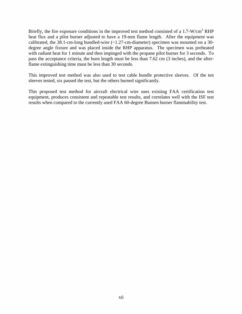
2.1.1.5.6 Procedure 5. In Procedure 5, the wire specimen was horizontal and the specimen length was reduced to 31.75 cm. The RHP was calibrated to a heat flux of 1.7 W/cm2. The wire or cable was installed on the wire-holding fixture, as shown in figure 12. This orientation provided a gradient heat flux across the length of the specimen. The tests were conducted following Procedure 4. After a 1-minute preheat, the pilot burner was impinged on the wire for 15 seconds. Burn length and after-flame extinguishing time were recorded.
Figure 12. Wire Mounted on the Sample Holder at a 0-Degree Angle (Horizontal)
2.1.1.5.7 Procedure 6. In Procedure 6, the wire specimen was returned to an orientation parallel to the RHP. The reduced wire specimen length of 31.75 cm was extended to 76.2 cm by using bare wire connected with an alligator clip (figures 13 and 14). Again, the tests were conducted following Procedure 4. After a 1-minute preheat, the pilot burner was impinged on the wire for 15 seconds. Burn length and after-flame extinguishing time were recorded.
14

Figure 13. Short Wire Mounted on the Sample Holder Using Alligator Clips
Figure 14. Short Wire Held With Alligator Clips
2.1.1.5.8 Procedure 7. In Procedure 7, the wire specimen gauge size was changed, and Procedure 4 was followed. The RHP was calibrated to a heat flux of 1.7 W/cm2. The wire gauge sizes were 24 and 10 AWG. After a 1-minute preheat, the pilot burner was impinged on the wire for 15 seconds. Burn length and after-flame extinguishing time were recorded.
15

16
2.1.1.5.9 Procedure 8. In Procedure 8, Procedure 4 was followed, but the pilot burner impingement time was reduced to 3 seconds. In addition, different wire gauge sizes were also evaluated, including 24, 20, 18, and 10 AWG. After a 1-minute preheat, the pilot burner was impinged on the wire for 3 seconds. Burn length and after-flame extinguishing time were recorded. 2.1.1.5.10 Procedure 9. In Procedure 9, the preheating time was eliminated, and Procedure 8’s 3-second pilot impingement time was followed. The RHP was calibrated to a heat flux of 1.7 W/cm2. The test specimen was a single 20-AWG or a premade cable comprised of smaller-gauge wires. Since the wire specimen was not preheated, the pilot burner was immediately impinged on the wire for 3 seconds. Burn length and after-flame extinguishing time were recorded. 2.1.1.5.11 Procedure 10. In Procedure 10, Procedure 8 was followed with bundled wires and cables, and wire protective sleeves. The bundled-wire specimens were reduced to 38.1 cm long. The RHP was calibrated to a heat flux of 1.7 W/cm2. Different wire gauges were also evaluated, including 24, 20, 18, and 10 AWG. After the 1-minute preheat, the pilot burner was impinged on the wire for 3 seconds. Burn length and after-flame extinguishing time were recorded. This test procedure was used to compare the results of a single-wire specimen with a bundled-wire specimen. 2.2 MATERIAL SELECTION.
Twenty-two wires and cables were selected with varying chemical compositions, gauge sizes, and temperature ratings that were expected to exhibit a wide range of flammability behavior. This wide range of flammability behavior was necessary to develop the improved flammability test method that correlated with the ISF tests. In addition, ten wire protective materials were selected. The selected wires and cables included 14 aviation-grade wires and cables and 8 wires and cables used in other industries, such as communications and consumer goods. In table 2, the wires with the alphanumeric code MS#, MS22759, or BMS13-# are aviation-grade wires and cables. The selected wires and cables had temperature ratings ranging from 60° to 260°C. Table 2 provides a description of the wires and cables. Figures 15 and 16 show photographs of the selected wire and cable specimens. The following sections provide information about the wire and cable specimens.

Table 2. Wires and Cables Specifications
Item No. Material Wire Specification AWG
Insulation Material
Jacket Material
TemperatureRating (°C) Comments
1 CAT 3 cable Hitachi riser cable CAT 3 (eight wires) 24 PVC Fire retardant thermoplastic
60 Use in other industries, flame-retardant jacket
2 CAT 5e cable Hitachi riser cable (CAT 5e) (eight wires) 24 Polyolefin Fire retardant thermoplastic
60 Use in other industries; polyolefin: polyethylene, polypropylene, cellular polyolefin, flame-retardant jacket
3 Computer cable
Polypropylene insulated computer cable, Belden 9804, 28 AWG, two pairs, shield: 90% overall foil/braid, drain wire overall
28 Polypropylene PVC 60 Use in other industries
4 M17/28-RG58 M17/28-RG58 (coaxial cable Type IIIA) 18 PE PVC 80 Use in other industries 5 Neoprene Neoprene hook-up wire 18 Neoprene - 90 Use in other industries 6 MS5086/1 MS5086/1 (~BMS13-13) 20/10 PVC Nylon 105 Past aircraft production 7 Fiber-optic
riser cable Fiber-optic riser cable (three fibers) 28 - PVC 105 Use in other industries
8 Hypalon Hypalon hook-up wire 18/10 Hypalon - 105 Use in other industries 9 MS22759/14 SAE AS22759/14 20 Extruded FEP PVDF 135 Aircraft-acceptable protected wire
listed in FAA AC 43.13-1B Table 11-12, past aircraft production
10 MS22759/16 MS22759/16 20 ETFE - 150 Aircraft-acceptable open wire listed in FAA AC 43.13-1B Table 11-11
11 MS22759/32 MS22759/32 20 Zelrad 150-S, XL-ETFE
- 150 Aircraft-acceptable protected wire listed in FAA AC 43.13-1B Table 11-12; current in-flight entertainment/other passenger systems
12 BMS13-48 BMS13-48 (~MS22759/34) 20 ETFE - 150 Aircraft-acceptable open wire listed in FAA AC 43.13-1B Table 11-11; current aircraft production; aircraft, in-flight entertainment/other passenger systems
13 BMS13-60 BMS13-60T01C01 20 Polyimide PTFE 150 Current aircraft production
17

18
Table 2. Wires and Cables Specifications (Continued)
Item No. Material Wire Specification AWG
Insulation Material
Jacket Material
TemperatureRating (°C) Comments
14 MS81044/6 MS81044/6 (~BMS13-38) 20 Cross-linked polyalkene
PVDF 150 Aircraft-acceptable open wire listed in FAA AC 43.13-1B Table 11-11; past aircraft production
15 MS81381/21 MS81381/21 20 Polyimide Tape Polyimide resin 150 Aircraft-acceptable protected wire listed in FAA AC 43.13-1B Table 11-12; past aircraft production
16 Silicone 200 Radix braidless silicone 200 lead wire 20 Silicone rubber - 200 Use in other industries 17 MS22759/33 SAE AS22759/33 24/20 Cross-linked ETFE
single layer - 200 Aircraft-acceptable protected wire
listed in FAA AC 43.13-1B Table 11-12; current in-flight entertainment/other passenger systems
18 BMS13-55 BMS13-55 20 Impregnated inorganic fiber
PTFE 200 Current aircraft production
19 BMS13-72 BMS13-72 20 PTFE FEP 200 Current aircraft production 20 MS22759/5 SAE AS22759/5 20 Extruded PTFE - 200 Aircraft-acceptable open wire listed
in FAA AC 43.13 1B Table 11-11; past aircraft production
21 MS22759/11 SAE AS22759/11 24/20 TFE - 200 Aircraft-acceptable protected wire listed in FAA AC 43.13-1B Table 11-12; past aircraft production
22 MS22759/86 SAE AS22729 (MS 22759/86) 20 Composite: fluoropolymer/PI tape
- 260 Current aircraft production; current in-flight entertainment/other passenger systems
CAT = Category ETFE = Ethylene-tetrafluoroethylene FEP = Fluorinated ethylene proplylene PE = Polyethylene PTFE = Polytetrafluoroethylene PVC = Polyvinylchloride PVDF = Polyvinylidene fluoride TFE = Tetrafluoroethylene
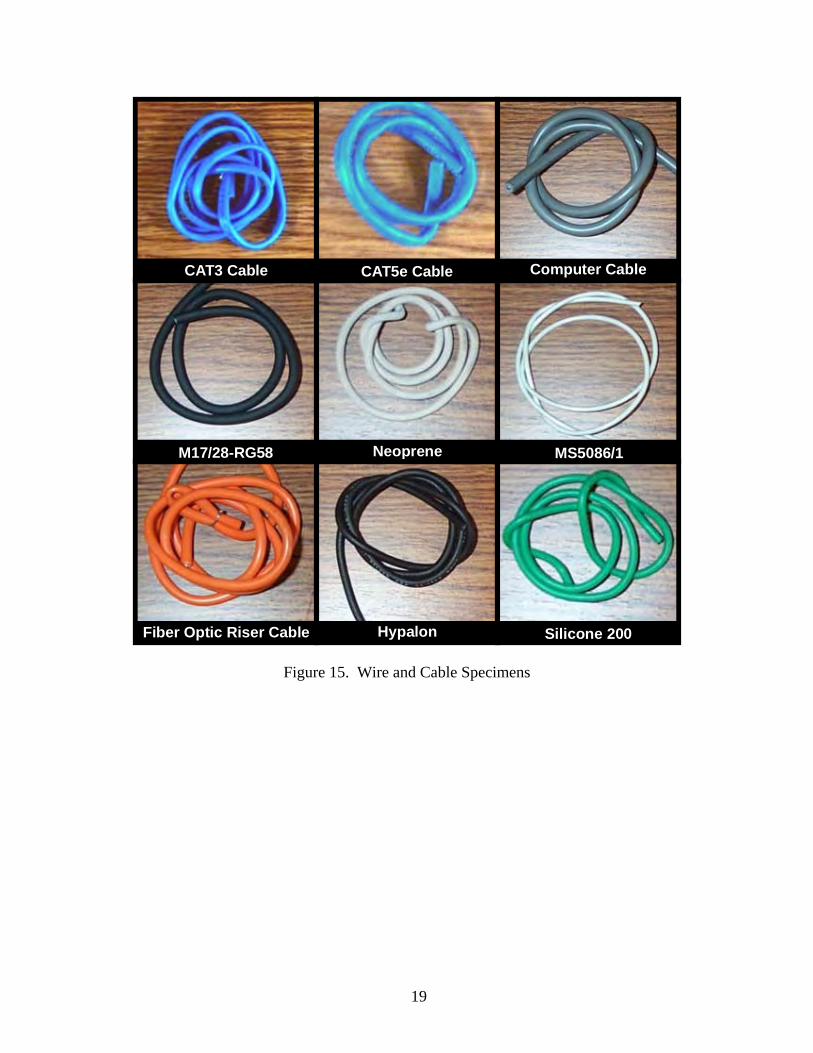
CAT5e Cable Computer CableCAT3 Cable
Neoprene MS5086/1M17/28-RG58
Hypalon Silicone 200Fiber Optic Riser Cable
Figure 15. Wire and Cable Specimens
19

MS22759/16 MS22759/32MS22759/14
BMS13-60 MS81044/6BMS13-48
MS22759/33 BMS13-55MS81381/21
MS22759/86
MS22759/5 MS22759/11BMS13-72
Figure 16. Current Aviation-Grade Wire and Cable Specimens
20

2.2.1 The CAT 3 Cable.
The Hitachi category (CAT) 3 riser cable is used in the voice and network communications industries. It is composed of two pairs of wires covered with an overall jacket. The wires are 24-AWG copper, insulated with polyvinylchloride (PVC); the overall jacket is made from an unidentified flame-retardant thermoplastic. A polyester-backed aluminum foil separates the wires from the overall jacket. This cable has a maximum temperature rating of 60°C. 2.2.2 CAT 5e Cable.
This Hitachi CAT 5e riser cable is used in the voice, broadband digital video, automated banking, and network communications industries. It is composed of two pairs of wires covered with an overall jacket. The wires are 24-AWG copper, insulated with polyolefin; the overall jacket is made from an unidentified flame-retardant thermoplastic. A polyester-backed aluminum foil separates the wires from the overall jacket. This cable has a maximum temperature rating of 60°C. 2.2.3 Computer Cable.
A Belden® model 9804 low-capacitance computer cable is used for data transmissions in the telecommunication industry. It is composed of two pairs of wires covered with an overall jacket. The twisted pairs of wires are 28-AWG copper, insulated with polypropylene; the overall jacket is made from PVC. A 100% Beldfoil braided shield separates the wires from the overall jacket. This cable has a maximum temperature rating of 60°C. 2.2.4 M17/28-RG58 Cable.
This coaxial cable is used for residential, commercial, and industrial installations of communications infrastructure, such as radio transmissions (broadcast), community antenna television, local area networks, and closed-circuit television. This cable had four major components: a center conductor, a dielectric core, a braided shield, and an outer jacket. The center core is a 20-AWG stranded (19x33), tinned copper conductor. The dielectric core or insulation is made of polyethylene (PE). The braided shield is tinned copper with 95% coverage. The black jacket is made of noncontaminating PVC. This cable had a maximum temperature rating of 85°C. 2.2.5 Neoprene Lead Wire.
This lead wire is used in applications where good heat aging and explosion-proof characteristics are needed, such as explosion-proof motors in hazardous locations. The insulation is neoprene and the single conductor is stranded (16x30) 18-AWG copper wire. This cable has a maximum temperature rating of 90°C.
21

2.2.6 Fiber-Optic Riser Cable.
This distribution cable is used for indoor connections, such as in-building backbone, fiber-to-the-desk applications, and computer rooms. This cable has five major components: core, cladding, coating, strengthening fibers, and outer jacket. The core, cladding, and coating materials are not specified by the manufacturer. The strengthening fibers are composed of aramid yarn and the jacket is made from PVC. This cable has a maximum temperature rating of 105°C. 2.2.7 Hypalon Lead Wire.
This lead wire is used in applications where heat resistance, color stability, and electrical properties are needed. This wire is recommended for motor leads for Class 130(B) insulation systems. The insulation is chlorosulfonated PE. The wire is a single-conductor, stranded (16x30) 18-AWG copper. This cable has a maximum temperature rating of 105°C. 2.2.8 MS5086/1 Lead Wire.
This lead wire is used in early DC-9, B-727, and B-737 aircraft until 1979. It is no longer used in aviation since it fails the current federal flammability tests. The insulation is PVC and the outer jacket is clear nylon. The conductor is 20-AWG stranded, tinned copper. This cable has a maximum temperature rating of 105°C. 2.2.9 MS22759/14 Lead Wire.
This lead wire is recommended by the FAA for aviation use in AC 43.13-1B. The commercial specification number is SAE AS22759/14-20. The insulation is extruded fluorinated ethylene propylene (FEP) and the jacket is clear polyvinylidene fluoride (PVDF). The conductor is 20-AWG stranded, tinned copper. This cable has a maximum temperature rating of 135°C. 2.2.10 BMS13-48-1 Lead Wire.
This lead wire is a wire specification that was developed by an aircraft manufacturer. The insulation is extruded cross-linked ethylene-tetreflouroethylene (ETFE). The conductor is 20-AWG stranded, tinned annealed copper. This cable has a maximum temperature rating of 150°C. 2.2.11 BMS13-60 Lead Wire.
This lead wire is a wire specification that was developed by an aircraft manufacturer. The insulation is a composite made of Teflon® and Kapton®. The construction of this wire is similar to the SAE AS22729. The conductor is 20-AWG stranded, tinned copper. This cable has a maximum temperature rating of 150°C.
22

2.2.12 MS22759/16 Lead Wire.
This lead wire is recommended by the FAA for aviation use in AC 43.13-1B. The commercial specification number is SAE AS22759/16-20. The insulation is ETFE. The conductor is 20-AWG stranded, tinned copper. This cable has a maximum temperature rating of 150°C. 2.2.13 MS22759/32 Lead Wire.
This lead wire is recommended by the FAA for aviation use in AC 43.13-1B. The commercial specification number is SAE AS22759/32-20. The insulation is Zelrad 150-S, fluoropolymer cross-linked modified ETFE. The conductor is 20-AWG stranded, tinned copper. This cable has a maximum temperature rating of 150°C. 2.2.14 MS81044/6 Lead Wire.
This lead wire is recommended by the FAA for aviation use in AC 43.13-1B. The insulation is extruded cross-linked polyalkene and the jacket is extruded cross-linked PVDF (XL-PVDF). The conductor is 20-AWG stranded, tinned copper. This cable has a maximum temperature rating of 150°C. 2.2.15 MS81381/21 Lead Wire.
This lead wire is listed in FAA AC 43.13-1B for aviation use, but it is identified as having susceptibility to arc tracking. The insulation is PI tape and the jacket is modified aromatic PI resin. The conductor is 20-AWG stranded, tinned copper. This cable has a maximum temperature rating of 150°C. 2.2.16 BMS13-72 Cable.
This data bus cable has a wire specification developed by an aircraft manufacturer. The outer jacket is FEP. The shield is flat and round copper with tin coating. The four 24-AWG conductors are stranded, silver-coated copper insulated with polytetrafluoroethylene (PTFE). This cable has a maximum temperature rating of 150°C. 2.2.17 MS22759/11 Lead Wire.
This lead wire is recommended by the FAA for aviation use in AC 43.13-1B. The commercial specification number is SAE AS22759/11-20. The insulation is nonstick tetrafluoroethylene (TFE). The conductor is 20-AWG stranded, silver-plated copper. This cable has a maximum temperature rating of 200°C. 2.2.18 MS22759/33 Lead Wire.
This lead wire is recommended by the FAA for aviation use in AC 43.13-1B. The commercial specification number is SAE AS22759/33-20. The insulation is cross-linked, modified ETFE. The conductor is 20-AWG stranded, silver-coated, high-strength copper. This cable has a maximum temperature rating of 200°C.
23

2.2.19 MS22759/5 Lead Wire.
This lead wire is recommended by the FAA for aviation use in AC 43.13-1B. The commercial specification number is SAE AS22759/5-20. The insulation is abrasion-resistant and extruded PTFE. The conductor is 20-AWG stranded, silver-coated copper. This cable has a maximum temperature rating of 200°C. 2.2.20 Silicone 200 Lead Wire.
This lead wire is recommended as a consumer appliance wiring material. The insulation is silicone rubber. The conductor is 20-AWG stranded, nickel-plated copper. This cable has a maximum temperature rating of 200°C. 2.2.21 BMS13-55 Lead Wire.
This lead wire has an aircraft manufacturer wire specification number. The insulation is an inorganic-fiber PTFE tape braid. The conductor is 20-AWG stranded, nickel-coated, annealed copper. This cable had a maximum temperature rating of 260°C. 2.2.22 MS22759/86 Lead Wire.
This lead wire has a commercial specification number labeled SAE AS22729 for aircraft applications. The insulation is a fluoropolymer (Teflon) and PI (Kapton) tape composite. The conductor is 20-AWG stranded, silver-coated copper. This cable has a maximum temperature rating of 260°C. 2.2.23 Wire Protective Materials.
Ten types of other wire protective materials were selected for this test project. They included expandable polyester sleeves (with small and large diameters), silicone/Kevlar sleeves (with and without fire retardant (FR)), NTFR-1/4-0-SP heat shrink, NTFR-3/16-0-SP heat shrink, NO324-1-F6 heat shrink, NO324-2-F6 heat shrink, Nomex/polyphenylene sulfide (PPS) sleeves (Roundit® 2000 NX), and Nomex/polyetheretherketone (PEEK) sleeves (Roundit 2000NX HT). 2.3 ANALYSIS.
A four-step analysis approach was used to design, evaluate, modify, and validate the improved wiring flammability test method. Each step was dependent on the following test method results: Bunsen burner test, ASTM D 7309-07 MSCC tests, ASTM E 2550-07 (TGA), ISF tests, and RHP tests. 1. Conduct the Bunsen burner test to evaluate the selected material specimens, establish a
comparative baseline, and determine compliance with existing regulations. The results of this test were compared with the results of the ISF test and the improved RHP flammability test.
24

25
2. Determine the flammability characteristics and thermal stability of the selected material specimens, using ASTM D 7309-07 (MSCC) and ASTM E 2550-07 (TGA), to assist in the establishment of the pass/fail criteria for the ISF test results.
3. Test the selected material specimens using the ISF test apparatus to determine their
flammability performance (burn length and after-flame extinguishing time) in a realistic and robust aircraft fire scenario. From these test results, the selected material specimens were categorized as fire worthy (pass) or non-fire-worthy (failed). For materials that were marginal (borderline), the results from ASTM D 7309-07 and ASTM E 2550-07 were used to set the acceptance criteria threshold.
4. Identify the initial conditions and test procedures for the RHP test apparatus that provided
similar results as the ISF tests. Critical RHP apparatus and specimen setup, and operational parameters were identified, examined, and modified until they matched the ISF test results (pass or fail). The critical parameters included sample configuration (single-wire or bundled-wire specimens), radiant heat setting, distance from the RHP, preheating time, mounting angle, and pilot flame impingement time.
To validate the improved RHP flammability test method, it was required that the pass/fail criteria matched the pass/fail results of the ISF test. The improved RHP flammability test method evaluation examined the effect of specimen wire gauge, configuration (single-wire or bundled-wire specimens), and length on the fire-worthy rating. 3. RESULTS.
3.1 THE FAA 60-DEGREE BUNSEN BURNER TEST FOR ELECTRICAL WIRE.
Table 3 shows the average results of the Bunsen burner test, and figure 17 shows a plot of the AFET versus ABL. Twenty of the twenty-two material specimens passed the test. Two materials, MS5086/1 and Silicone 200, failed the test; they both exceeded the maximum after-flame extinguishing time (30 seconds) and the maximum burn length (7.6 cm) as specified in the FAA regulation. None of the material specimens exhibited flaming drippings. As shown in table 3, for those materials that passed, the difference in burn length between the best performing material (MS22759/86) and the worst (CAT 5e cable) was only 3.8 cm. Similarly, the difference between the after-flame extinguishing time between the best (MS22759/86) and the worst (M17/28-RG58) specimen was only 3.3 seconds. Therefore, this test did not discriminate between the performances of different materials as exhibited during the ISF tests, which clearly differentiated between fire worthy and non-fire-worthy insulation materials. Nine of the 22 material specimens were determined to be non-fire-worthy during the ISF tests. The failed specimens were the non-aviation-grade types, with the exception of MS5086/1, which was an old aviation-grade wire.

Table 3. Average Results of the Wire and Cable Bunsen Burner Tests
Item No. Material
Average Burn Length (cm)
Average Flame- Extinguishing Time
(sec)
Average Drip Flame- Extinguishing Time
(sec)
Average Mass Loss
(g) Conductor Exposed? Comments
1 MS22759/86 2.7 0.0 0.0 0.1 No Passed 2 BMS13-60 3.0 0.0 0.0 0.0 No Passed 3 MS81381/21 3.2 0.0 0.0 0.2 No Passed 4 BMS13-72 3.7 0.0 0.0 0.0 No Passed 5 MS22759/11 3.8 0.0 0.0 0.1 Yes Passed 6 MS22759/32 3.8 0.0 0.0 0.0 Yes Passed 7 MS22759/14 4.2 0.0 0.0 0.1 Yes Passed 8 MS22759/5 4.4 0.0 0.0 0.0 No Passed 9 BMS13-55 4.6 0.0 0.0 0.1 No Passed
10 BMS13-48 4.6 0.0 0.0 0.1 Yes Passed 11 MS81044/6 4.9 2.3 0.0 0.1 Yes Passed 12 MS22759/16 5.1 0.0 0.0 0.2 Yes Passed 13 MS22759/33 5.3 0.0 0.0 0.1 Yes Passed 14 Fiber-optic riser cable 5.6 0.0 0.0 0.3 Yes Passed 15 Computer cable 5.6 0.7 0.0 0.1 No Passed 16 CAT 3 cable 6.0 2.0 0.0 0.3 No Passed 17 Hypalon 6.4 1.0 0.0 0.2 No Passed 18 Neoprene 6.2 1.0 0.0 0.3 Yes Passed 19 M17/28-RG58 6.2 3.3 0.0 0.2 No Passed 20 CAT 5e cable 6.5 0.3 0.0 0.7 No Passed 21 Silicone 200 18.2 166.0 0.0 0.6 Yes Failed 22 MS5086/1 39.6 148.3 0.0 1.1 Yes Failed
26
Pass/fail criteria: AVL ≤7.6 cm, AFET ≤30 sec, average drip-extinguishing time ≤3 sec

0
5
10
15
20
25
30
35
40
45
50
0 10 20 30 40 50 60 70 80 90 100 110 120 130 140 150 160 170 180
Average Flame Extinguishing Time (sec)
Ave
ra
Requirements: (1) Average Flame Extinguishing Time <= 30 seconds
(3) Average Drip Flame Extinguishing Time <= 3 seconds
27
Figure 17. The 60-Degree Bunsen Burner Test Results
geB
urn
Leng
th(c
m)
Silicone 200
MS5086/1MS22759/86BMS13-60
MS81381/21BMS13-72
MS22759/11MS22759/32MS22759/14MS22759/5BMS13-55BMS13-48MS81044/6MS22759/16MS22759/33 CFiber able
Com ble
M17/28-RG58CAT5e Cable
Optic Riser puter Ca
CAT3 CableHypalon
Neoprene
Note: All wire samples had zero second drixtinguishing time
p e
MS22759/86 BMS13-60
MS81381/21 BMS13-72
MS22759/11 MS22759/32 MS22759/14 MS22759/5 BMS13-55 BMS13-48 MS81044/6
MS22759/16 MS22759/33
Fiber-optic riser cable Computer cable
CAT 3 cable Hypalon
Neoprene M17/28-RG58 CAT 5e cable
Note: All wire samples had zero-second drip flame extinguishing time

3.2 MICROSCALE COMBUSTION CALORIMETRY (ASTM D 7309-07).
MSCC tests were conducted to determine the flammability characteristics of the selected wires. The flammability characteristics included onset temperature, combustion temperature, specific heat of combustion of the specimen gases, heat release capacity, and pyrolysis residue (figure 18). Table 4 shows the average values of the wire flammability characteristics. Figure 19 is a plot of the onset temperature versus the specific heat of combustion of the specimen gases; it is shown that the most fire-worthy materials are located on the lower-right-hand corner, inside the dotted-line box. These flammability characteristics were used to predict the flammability performance of the wire and cable specimens during the various fire tests and to set the pass/fail criteria for the ISF test.
0
50
100
150
200
250
300
350
400
0 100 200 300 400 500 600 700 800 900 1000
Temperature (degC)
Hea
t Rel
ease
Rat
e (W
/g)
Specific Heat of Combustion (Area under the curve)
Heat Release Capacity (Sum of all HRR peaks divided by the heating rate)
Onset Temperature
Combustion Temperature
Figure 18. Typical MSCC Flammability Characteristics
28

Table 4. Average Results of the MSCC Test of Wires and Cables
Item No. Material
Onset Temperature
(°C)
CombustionTemperature
(°C)
Heat Release Capacity (J/g-K)
Specific Heat of
Combustion(kJ/g)
Pyrolysis Residue
(%)
Specific Heat of Combustion
of Specimen Gas(kJ/g)
1 Hypalon 191 292 1,182 11.9 36.3 18.6 2 Neoprene 201 306 1,187 06.8 57.7 16.1 3 Computer cable (all components) 221 N/A 1,872 32.8 N/A 33.4 4 Computer cable (jacket) 221 317 1,195 11.6 00.0 11.6 5 CAT 3 cable (all components) 237 N/A 1,453 11.1 N/A 15.2 6 CAT 3 cable (jacket) 237 284 1,379 11.3 26.3 15.3 7 Fiber-optic riser cable (all
components) 237 N/A 1,349 11.8 N/A 15.4
8 Fiber-optic riser cable (jacket) 237 300 1,357 12.7 18.5 15.6 9 CAT 3 cable (insulation) 242 272 1,470 10.3 32.0 15.1
10 M17/28-RG58 (all components) 262 N/A 1,773 30.4 N/A 31.3 11 M17/28-RG58 (jacket) 262 505 1,487 25.0 05.0 26.3 12 CAT 5e cable (all components) 263 N/A 1034 33.6 N/A 35.5 13 CAT 5e cable (jacket) 263 319 1,306 12.1 34.7 18.5 14 MS5086-1 280 344 1,281 18.6 15.9 22.1 15 Computer cable (string) 312 363 1,128 07.9 15.7 09.4 16 Fiber-optic riser cable (insulation) TBD 286 1,236 05.3 46.0 09.8 17 MS81044-6 343 501 1,373 16.0 22.7 20.7 18 Computer cable (foil) 413 459 1,144 06.8 60.3 17.1 19 Computer cable (fibers) 419 439 1,381 15.8 11.9 17.9 20 MS22759/33 424 502 1,163 06.6 13.3 07.6 21 MS22759/32 424 501 1,171 06.5 14.5 07.6 22 M17/28-RG58 (insulation) 426 498 1415 42.6 00.0 42.6 23 BMS13-48 448 499 0110 04.7 20.4 05.9 24 Computer cable (insulation) 450 483 1160 41.7 00.0 41.7 25 CAT 5e cable (insulation) 456 505 1310 41.7 00.7 42.0
29

30
Table 4. Average Results of the MSCC Test of Wires and Cables (Continued)
Item No. Material
Onset Temperature
(°C)
CombustionTemperature
(°C)
Heat Release Capacity (J/g-K)
Specific Heat of
Combustion (kJ/g)
Pyrolysis Residue
(%)
Specific Heat of Combustion
of Specimen Gas(kJ/g)
26 MS22759/16 458 517 255 09.4 06.5 10.0 27 MS22759/14 469 491 060 03.1 11.1 03.5 28 BMS13-72 (all components) 491 N/A 046 02.3 N/A 02.4 29 BMS13-72 (jacket) 491 534 068 02.8 00.5 02.8 30 MS22759/11 515 627 046 02.7 00.6 02.7 31 MS22759/86 541 615 031 01.8 17.8 02.2 32 BMS13-72 (insulation) 543 617 038 02.2 00.0 02.2 33 BMS13-55 546 534 043 02.8 00.5 02.8 34 MS22759/5 550 604 055 02.7 01.3 02.7 35 BMS13-60 553 612 032 02.1 16.1 02.5 36 MS81381/21 566 626 018 01.6 59.3 04.0 37 Silicone 200 577 498 142 12.4 49.8 24.6 38 Fiber-optic riser cable (fibers) 580 606 378 12.6 38.0 20.4

0
10
20
30
40
50
60
0 100 200 300 400 500 600 700
31
Figure 19. The MSCC Test Results: Onset Temperature Versus Specific Heat of Combustion of the Gas
Onset Temperature (degC)
Spec
ific
Hea
tofC
ombu
stio
n,G
as,h
cg(k
J/g)
M17/28-RG58 (All Components)
CAT 5e (All Components)
Computer Cable (All Components)
Silicone 200
MS5086/1
HypalonCAT 3 (All Components)
Fiber Optic Cable (All Components)
Neoprene
MS81044/6
MS22759/16
MS22759/32MS22759/33
BMS13-48MS22759/14BMS13-72 (All Components)
MS22759/11
MS22759/86BMS13-55MS22759/5BMS13-60
MS81381/21Tos
>33
5de
gC
hcg < 21 kJ/g
Note: - Passed the ISF Test
Failed the ISF TestGreen Diamond
-Red Diamond
Spec
ific
Hea
t of C
ombu
stio
n of
the
Gas
(kJ/
g)
Onset Temperature (°C)

Some of the material specimens were cables. The cables were disassembled and their components, such as jackets, insulations, foils, fibers, and strings were tested individually. The mass fractions of these individual components were computed and used to determine the flammability characteristics for the whole cable. The flammability characteristics of these individual and combined components are reported in table 4. Only the combined components results are plotted in figure 19. The percent of pyrolysis residue was used to compute the specific heat of combustion of the specimen gases as defined in the ASTM standard. The results of this computation are reported in table 4. After characterizing the flammability characteristics of the wire insulation materials, it was observed that the following properties determined fire worthiness by the ISF test: an onset temperature greater than 335°C, a combustion temperature greater than 485°C, a specific heat of combustion of the specimen gases lower than 21 kJ/g, and a heat release capacity lower than 375 J/g-K (figure 20). All of the aviation-grade wires, with the exception of MS5086/1 (no longer in use), exhibited these flammability characteristics. Therefore, this ASTM test method is useful to determine the flammability characteristics of aircraft wire if enough insulation material is not available to conduct the improved wire flammability test. The temperature rating of these aviation-grade wires ranged between 135° and 260°C. However, non-aviation-grade wires and cables, with a temperature rating between 60° and 105°C, did not have these desirable properties.
Tos
h , c gas
<375 J/g-K<21 KJ/g
Desirable FlammabilityCharacteristics Box (Volume)*
Heat ReleaseCapacity
Specific Heatof Combustion of Specimen gases
Note:Acceptable MaterialUnacceptable Material
O
>335 COnsetTemperature
C
Figure 20. Aircraft Wire Insulation Flammability Characteristics Box
32

3.3 THERMOGRAVIMETRIC ANALYSIS.
The TGA tests, in an anaerobic condition (nitrogen environment), were conducted to determine the thermal stability of the wire specimens. The TGA results are presented in table 5. This table presents the ML onset temperature, decomposition temperature, and percent char of the wires and cables specimens (figure 21).
Table 5. Thermogravimetric Analysis Test Data
Item No. Material
Mass Loss Onset
Temperature at 0.5%
(°C)
Decomposition Temperature 1
(°C)
Decomposition Temperature 2
(°C) % Char 1 Hypalon 142 269 468 35.3 2 Neoprene 176 317 N/A 60.7 3 CAT 3 cable (insulation) 195 280 N/A 29.1 4 CAT 3 cable (jacket) 203 288 N/A 24.0 5 Fiber-optic riser cable (Kevlar fibers) 214 603 N/A 37.8 6 Fiber-optic riser cable (jacket) 219 284 309 18.4 7 CAT 5e cable (jacket) 220 302 N/A 28.8 8 Computer cable (jacket) 229 294 N/A 25.1 9 M17/28-RG58 (jacket) 236 271 373 13.3
10 MS5086-1 236 329 436 17.1 11 Computer cable (foil) 276 439 N/A 61.3 12 Silicone 200 279 573 N/A 48.8 13 Computer cable (insulation) 284 463 N/A 00.0 14 CAT 5e cable (insulation) 305 480 N/A 00.0 15 MS22759/32 305 483 N/A 13.6 16 MS22759/33 317 484 N/A 16.1 17 MS81044-6 322 400 480 21.1 18 BMS13-48 340 470 N/A 22.3 19 M17/28-RG58 (insulation) 372 481 N/A 00.0 20 MS22759/16 411 489 N/A 08.9 21 MS22759/14 415 418 591 11.0 22 MS81381/21 452 594 N/A 63.2 23 BMS13-72 (jacket) 454 595 N/A 00.0 24 MS22759/86 465 592 N/A 16.0 25 BMS13-60 477 590 N/A 15.2 26 MS22759/11 489 599 N/A 00.0 27 BMS13-72 (insulation) 490 596 N/A 00.0 28 BMS13-55 493 597 N/A 40.7 29 MS22759/5 505 603 N/A 00.9
33

200 300 400 500 600 700 800 900 1000
Decomposition Temperature
Mass Loss Onset Temperature
0.12
0.09
0.06
0.03
0 100
10
9
8
7
6
5
4
3
2
1
0 0
0.15
Mass R
ate of Change / %
min
Mas
s (m
g)
DTGTG
-1
Temperature (°C)
Figure 21. Typical TG and DTG Curves
The aviation-grade wires were more thermally stable at higher temperatures than the consumer or communications wires; their ML onset temperatures were greater than 300ºC, and their decomposition temperatures were greater than 400ºC (at 95% confidence level). The reported ML onset temperatures in table 5 did not match the MSCC onset temperatures (table 4) because they are defined differently. The onset temperature in table 4 was extrapolated, while the onset temperature in table 5 was determined at the temperature where the mass decreased 0.5% from the initial mass prior to the thermal event. 3.4 INTERMEDIATE-SCALE FIRE TEST.
As discussed in section 2.1.1.4, ISF tests were conducted to evaluate the flammability performance of the selected wires and cables with a robust fire inside the cabin attic of a narrow-body aircraft (figure 22). Tables 6 and 7 show the peak temperatures and peak heat fluxes, respectively, and table 8 shows the flammability performance of the tested specimens.
34

Figure 22. Intermediate-Scale Fire Test Apparatus
Initially, five baseline tests were conducted to determine the temperature and heat flux profile of the ignition source (urethane foam block) alone inside the aircraft cabin attic. Tables 6 and 7 show that the average peak temperature and average peak heat flux of the ignition source was 791.4°C and 8.5 W/cm2, respectively. Figures 23 and 24 show the urethane foam block temperature and heat flux histories for a single test. The foam block fire peaks at around 1 minute after ignition and gradually decreases before extinguishing around 8 minutes later. The seven thermocouples along the ceiling show the temperature decreased with distance from the ignition source (figure 23). On figure 25, the onset temperature range of the selected wires and cables are plotted over the baseline average temperature profile. It shows that the ignition source temperature was high enough to ignite them and promote combustion; hypalon had the lowest combustion temperature, 191°C, and the fiber-optic riser cable (FORC) (fibers) had the highest combustion temperature, 580°C.
35

Table 6. Intermediate-Scale Fire Test of Wires and Cables: Peak Temperature
Temperature (°C) Item No. Material Test 1 Test 2 Test 3 Test 4 Test 5 Average
Standard Deviation
1 Baseline 677.1 717.9 852.0 852.8 857.3 791.4 87.0 2 BMS13-48 607.5 660.3 788.8 N/A N/A 685.5 93.2 3 BMS13-55 715.9 737.1 815.0 N/A N/A 756.0 52.2 4 BMS13-60 750.4 816.5 841.3 N/A N/A 802.7 47.0 5 BMS13-72 689.6 711.0 848.9 N/A N/A 749.8 86.4 6 CAT 3 cable 813.3 820.5 832.0 N/A N/A 821.9 9.4 7 CAT 5e cable 754.0 805.0 890.0 N/A N/A 816.3 68.7 8 Computer cable 772.5 786.8 814.4 N/A N/A 791.2 21.3 9 FORC 821.5 831.8 886.3 N/A N/A 846.5 34.8
10 Hypalon 790.4 801.6 818.6 N/A N/A 803.5 14.2 11 M17/28-RG58 656.9 825.3 883.0 N/A N/A 788.4 117.5 12 MS22759/11 747.6 776.4 833.9 N/A N/A 786.0 43.9 13 MS22759/14 739.9 769.1 784.1 N/A N/A 764.4 22.5 14 MS22759/16 734.5 789.1 825.3 N/A N/A 783.0 45.7 15 MS22759/32 764.4 773.5 840.8 N/A N/A 792.9 41.7 16 MS22759/33 729.3 790.8 803.6 N/A N/A 774.6 39.7 17 MS22759/5 703.0 738.6 819.8 N/A N/A 753.8 59.8 18 MS22759/86 800.0 841.1 862.3 N/A N/A 834.5 31.7 19 MS5086/1 881.1 884.3 913.1 N/A N/A 892.8 17.6 20 MS81044/6 778.0 821.8 846.8 N/A N/A 815.5 34.8 21 MS81381/21 772.0 793.5 800.0 N/A N/A 788.5 14.7 22 Neoprene 773.9 794.3 869.4 N/A N/A 812.5 50.3 23 Silicone 200 766.0 831.3 838.5 N/A N/A 811.9 39.9
Table 7. Intermediate-Scale Fire Test of Wires and Cables: Peak Heat Flux
Heat Flux (W/cm2) Item No. Material Test 1 Test 2 Test 3 Test 4 Test 5 Average
Standard Deviation
1 Baseline 6.3 7.1 08.3 9.0 11.7 8.5 2.1 2 BMS13-48 7.7 9.9 11.7 N/A N/A 9.8 2.0 3 BMS13-55 6.3 6.8 08.1 N/A N/A 7.1 0.9 4 BMS13-60 8.1 8.1 08.9 N/A N/A 8.4 0.4 5 BMS13-72 6.8 7.2 11.7 N/A N/A 8.6 2.7 6 CAT 3 cable 8.8 9.7 00.0 N/A N/A 6.2 5.4 7 CAT 5e cable 8.6 9.2 09.2 N/A N/A 9.0 0.3 8 Computer cable 7.9 8.9 09.2 N/A N/A 8.7 0.7 9 FORC 7.0 9.0 09.7 N/A N/A 8.6 1.4
36

Table 7. Intermediate-Scale Fire Test of Wires and Cables: Peak Heat Flux (Continued)
Heat Flux (W/cm2) Item No. Material Test 1 Test 2 Test 3 Test 4 Test 5 Average
Standard Deviation
10 Hypalon 8.0 08.9 09.1 N/A N/A 08.7 0.6 11 M17/28-RG58 9.0 09.6 09.7 N/A N/A 09.4 0.4 12 MS22759/11 7.1 07.2 08.0 N/A N/A 07.4 0.5 13 MS22759/14 7.2 07.2 08.6 N/A N/A 07.7 0.8 14 MS22759/16 8.1 09.0 09.1 N/A N/A 08.7 0.6 15 MS22759/32 8.6 09.0 09.9 N/A N/A 09.2 0.7 16 MS22759/33 6.5 06.5 08.0 N/A N/A 07.0 0.9 17 MS22759/5 7.7 08.6 11.7 N/A N/A 09.3 2.1 18 MS22759/86 9.0 10.0 10.9 N/A N/A 10.0 1.0 19 MS5086/1 8.9 09.8 10.6 N/A N/A 09.8 0.9 20 MS81044/6 7.9 08.3 08.2 N/A N/A 08.1 0.2 21 MS81381/21 8.6 08.6 09.0 N/A N/A 08.7 0.3 22 Neoprene 8.1 09.0 11.4 N/A N/A 09.5 1.7 23 Silicone 200 8.0 08.6 09.9 N/A N/A 08.8 0.9
Table 8. Intermediate-Scale Fire Test Results: Flammability Data
Item No. Material
Maximum After-Flame
Extinguishing Time (min)
Maximum Burn
Length (cm)
Maximum Mass Loss
(%) Pass/Fail Decision Comments
1 MS22759/11 1.4 28.0 0.30 Passed More than half of the conductors were exposed after the fire.
2 MS22759/86 1.4 44.0 0.40 Passed No conductors were exposed after the fire.
3 BMS13-60 1.4 29.5 0.35 Passed Less than a quarter of the conductors were exposed after the fire.
4 BMS13-48 1.5 42.9 0.90 Passed More than half of the conductors were exposed after the fire.
5 MS81381/21 1.5 20.7 0.10 Passed Less than a quarter of the conductors were exposed after the fire.
6 MS22759/32 1.5 36.6 0.70 Passed All conductors were exposed after the fire.
7 MS22759/33 1.7 37.9 1.40 Passed All conductors were exposed after the fire.
8 MS22759/16 1.8 33.0 0.30 Passed More than half of the conductors were exposed after the fire.
37

Table 8. Intermediate-Scale Fire Test Results: Flammability Data (Continued)
Item No. Material
Maximum After-Flame
Extinguishing Time (min)
Maximum Burn
Length (cm)
Maximum Mass Loss
(%) Pass/Fail Decision Comments
9 BMS13-72 1.8 022.5 0.10 Passed No conductors were exposed after the fire, but the meshed metal shield was exposed.
10 MS22759/14 2.0 030.5 0.30 Passed More than half of the conductors were exposed after the fire.
11 BMS13-55 02.0 31.3 0.20 Passed No conductors were exposed after the fire.
12 CAT 3 Cable 02.0 096.9 3.70 Failed All conductors were exposed after the fire.
13 FORC 02.3 068.5 4.00 Failed No conductors were exposed after the fire.
14 MS81044/6 02.4 032.4 1.10 Passed Less than half of the conductors were exposed after the fire.
15 MS22759/5 02.9 022.3 0.20 Passed Half of the conductors were exposed after the fire.
16 Computer cable 03.2 049.0 4.10 Failed Less than a quarter of the conductors were exposed after the fire.
17 Neoprene 04.3 097.0 11.60 Failed All conductors were exposed after the fire.
18 Silicone 200 05.2 040.8 01.70 Failed More than half of the conductors were exposed after the fire.
19 Hypalon 06.8 132.5 17.30 Failed All conductors were exposed after the fire.
20 CAT 5 cable 06.9 065.1 07.10 Failed All conductors were exposed after the fire.
21 MS5086/1 09.5 105.0 10.00 Failed All conductors were exposed after the fire.
22 M17/28-RG58 17.9 109.8 13.80 Failed All conductors were exposed after the fire.
38

0
100
200
300
400
500
600
700
800
900
1000
0 1 2 3 4 5 6 7 8 9 10 11 12 13 14 15
Time (Min)
Tem
pera
ture
(Deg
C)
Ceiling Temp 1 (degC)
Ceiling Temp 2 (degC)
Ceiling Temp 3 (degC)
Ceiling Temp 4 (degC)
Ceiling Temp 5 (degC)
Ceiling Temp 6 (degC)
Ceiling Temp 7 (degC)
Figure 23. Intermediate-Scale Fire Test Baseline Temperature
0
1
2
3
4
5
6
7
8
9
10
0 1 2 3 4 5 6 7 8 9 10 11 12 13 14 15
Time (Min)
Hea
t Flu
x (W
/cm
2)
FWD Ceiling Heat FluxCTR Ceiling Heat FluxAFT Ceiling Heat Flux
Figure 24. Intermediate-Scale Fire Test Baseline Heat Flux
39

0
100
200
300
400
500
600
700
800
900
0 1 2 3 4 5 6 7 8 9 10 11 12 13 14 15Time (Min)
Average Baseline Temperature
Min Wire Onset Temperature
Max Wire Onset Temperature
Minimum Example: Hypalon Insulated Wire (T os = 191 degC)
Maximum Example:Fiber Optic Riser Cable Fibers (Tos = 580 degC)
Tem
pera
ture
(°C
)
Selected Wires and Cables Onset Temperature Range
Figure 25. Average ISF Test Baseline Temperature (Threat) Versus Wires and Cables Onset Temperature Range
The peak temperature histories of the selected wires and cables during the ISF tests are shown in four plots, figures 26 through 29. The flammability data of the selected wires and cables are presented in table 8 and figure 30. The main flammability parameters recorded were burn length and after-flame extinguishing time. Information about their ML and conductor exposure were also recorded. Table 8 shows that the aviation-grade wires experienced burn lengths ranging from 20.7 to 44 cm and after-flame extinguishing times from 1.4 to 2.9 minutes. The non-aviation-grade wires experienced greater burn lengths, ranging from 40.8 to 132.5 cm, and greater after-flame extinguishing times, ranging from 2 to 17.9 minutes. Similarly, the aviation-grade wires experienced less ML, ranging from 0.1% (MS81381/21 and BMS13-72) to 1.4% (MS22759/33). The non-aviation-grade ML ranged from 1.7% (Silicone 200) to 17.3% (hypalon). Conductor exposure, after the fire test, was also recorded in table 8. Only two wires did not have bared conductors—MS22759/86 and BMS13-55. MS22759/86 had a composite insulation made of a fluoropolymer and PI tape, and BMS13-55 had an insulation made of inorganic fibers and PTFE. The material specimens with exposed conductors were made of PVC, neoprene, silicone, nylon, TFE, ETFE (including cross-linked), polyalkene, PVDF, and FEP.
40

0
100
200
300
400
500
600
700
800
900
1000
0 1 2 3 4 5 6 7 8 9 10 11 12 13 14 15
Time (Min)
Tem
pera
ture
(deg
C)
Avg BaselineBMS13-48BMS13-55BMS13-60BMS13-72CAT3 CableCAT5e Cable
Figure 26. Intermediate-Scale Fire Test of Wires and Cables (Plot 1): Thermocouple 4
0
100
200
300
400
500
600
700
800
900
1000
0 1 2 3 4 5 6 7 8 9 10 11 12 13 14 15
Time (Min)
Tem
pera
ture
(deg
C)
Avg BaselineComputer CableFiber OpticHypalonM17/28-RG58MS22759/5MS22759/11
Figure 27. Intermediate-Scale Fire Test of Wires and Cables (Plot 2): Thermocouple 4
41

42
0
100
200
300
400
500
600
700
800
900
1000
0 1 2 3 4 5 6 7 8 9 10 11 12 13 14 15
Time (Min)
Tem
pera
ture
(deg
C)
Avg BaselineMS22759/14MS22759/16MS22759/32MS22759/33MS22759/86MS5086/1
Figure 28. Intermediate-Scale Fire Test of Wires and Cables (Plot 3): Thermocouple 4
0
100
200
300
400
500
600
700
800
900
1000
0 1 2 3 4 5 6 7 8 9 10 11 12 13 14 15
Time (Min)
Tem
pera
ture
(deg
C)
Avg Baseline
MS81044/6
MS81381/21
Neoprene
Silicone 200
Figure 29. Intermediate-Scale Fire Test of Wires and Cables (Plot 4): Thermocouple 4

43
0
20
40
60
80
100
120
140
0 2 4 6 8 10 12 14 16 18 20
Maximum Extinguishing Time (min)
Max
imum
Bur
nLe
ngth
(cm
)
Hypalon
M17/28-RG58
MS5086/1
Figure 30. Intermediate-Scale Fire Test Results: Maximum Flame-Extinguishing Time Versus Maximum Burn Length
Computer Cable
Legend: Green Diamond - Passed Test
- Failed TestRed Diamond
Silicone 200
Fiber Optic Riser Cable
CAT3 Cable
Neoprene
AVIATION WIRES:MS22759/86BMS13-48
MS22759/33MS22759/32MS22759/16MS81044/6BMS13-55BMS13-60
MS22759/11BMS13-72MS22759/5MS81381/21
CAT5e Cable
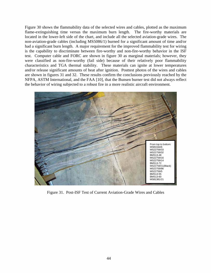
Figure 30 shows the flammability data of the selected wires and cables, plotted as the maximum flame-extinguishing time versus the maximum burn length. The fire-worthy materials are located in the lower-left side of the chart, and include all the selected aviation-grade wires. The non-aviation-grade cables (including MS5086/1) burned for a significant amount of time and/or had a significant burn length. A major requirement for the improved flammability test for wiring is the capability to discriminate between fire-worthy and non-fire-worthy behavior in the ISF test. Computer cable and FORC are shown in figure 30 as marginal materials; however, they were classified as non-fire-worthy (fail side) because of their relatively poor flammability characteristics and TGA thermal stability. These materials can ignite at lower temperatures and/or release significant amounts of heat after ignition. Posttest photos of the wires and cables are shown in figures 31 and 32. These results confirm the conclusions previously reached by the NFPA, ASTM International, and the FAA [10], that the Bunsen burner test did not always reflect the behavior of wiring subjected to a robust fire in a more realistic aircraft environment.
From top to bottom:MS81044/6MS22759/33MS22759/32BMS13-48MS22759/16MS22759/14BMS13-72MS22759/11(Black)MS22759/86MS22759/5BMS13-55BMS13-60MS81381/21
Figure 31. Post-ISF Test of Current Aviation-Grade Wires and Cables
44

From left to right: Hypalon Neoprene Computer cable CAT 3 cable Fiber-Optic riser cable M17/28-RG58 CAT 5e cable MS5086/1 Silicone 200
Figure 32. Post-ISF Test of Other Wires and Cables
3.5 RADIANT HEAT PANEL TEST.
As mentioned in section 2.1.1.5, the RHP test apparatus was evaluated as a possible replacement to the currently used Bunsen burner test for electrical wire. Two of the acceptance criteria of the Bunsen burner test method were retained: the average extinguishing time must be 30 seconds or less, and the ABL must be 7.6 cm or less. Material dripping after-flame time was not included because the aviation-grade wires did not drip and some poor performing wires and cables burn for so long (when they were dripping) that the dripping time was insignificant compared to the specimen’s after-flame extinguishing time. The following subsections discuss the results of each test procedure. Some procedures were requested by the International Aircraft Material Fire Test Working Group members to examine different configurations and settings. 3.5.1 Procedure 1.
In Procedure 1, the RHP was calibrated to a heat flux of 1.7 W/cm2. The single 76.2-cm-long wire or cable (20-AWG) was installed on the wire-holding fixture at an angle of 30 degrees to be paralleled with the RHP at a distance of 19 cm. The wire was preheated for 1 minute and the pilot burner was impinged on the wire for 30 seconds. The test record showed that the wire broke apart due to the intensity of the pilot burner at approximately 20 to 25 seconds. The burn length and after-flame extinguishing time were not recorded.
45

3.5.2 Procedure 2.
In Procedure 2, the pilot burner impingement time was decreased to 15 seconds. The results of this test procedure are shown in table 9 and figure 33. Two materials, FORC and CAT 3 cable, passed the test criteria, but were not fire worthy in the ISF test. Therefore, this test procedure was unacceptable.
Table 9. Average Results of the RHP Test of Wires and Cables, Procedure 2
Item No. Material
Average Flame-
ExtinguishingTime (sec)
Average Flame-
ExtinguishingTime
Standard Deviation
AverageBurn
Length (cm)
Average Burn
Length Standard Deviation
(cm) Pass/Fail Criteria
Matched ISF
Test? 1 MS22759/86 0.0 0.0 1.7 0.1 Passed Yes 2 BMS13-60 0.0 0.0 1.9 0.1 Passed Yes 3 BMS13-55 0.0 0.0 1.9 0.1 Passed Yes 4 BMS13-72 0.0 0.0 2.2 0.1 Passed Yes 5 MS81381/21 0.0 0.0 1.7 0.2 Passed Yes 6 MS22759/5 0.0 0.0 1.6 0.2 Passed Yes 7 MS22759/11 0.0 0.0 1.7 0.2 Passed Yes 8 MS22759/14 0.0 0.0 3.1 0.5 Passed Yes 9 MS22759/16 0.0 0.0 3.6 0.2 Passed Yes
10 MS22759/32 0.0 0.0 4.5 0.0 Passed Yes 11 MS22759/33 0.0 0.0 4.6 0.1 Passed Yes 12 BMS13-48 0.3 0.6 3.2 0.3 Passed Yes 13 MS81044/6 4.3 4.0 2.7 0.3 Passed Yes 14 CAT 3 cable 4.7 1.5 4.2 0.6 Passed No 15 FORC 6.7 5.5 5.1 0.5 Passed No 16 M17/28-RG58 60.0 — 15.0 — Failed Yes 17 Computer cable 125.0 41.6 36.0 2.3 Failed Yes 18 Neoprene 161.3 25.1 24.7 2.8 Failed Yes 19 MS5086/1 169.3 17.2 40.5 1.7 Failed Yes 20 CAT 5e cable 257.0 44.5 38.5 3.1 Failed Yes 21 Hypalon 276.7 12.3 41.3 0.7 Failed Yes 22 Silicone 200 439.0 18.0 41.3 2.0 Failed Yes
46
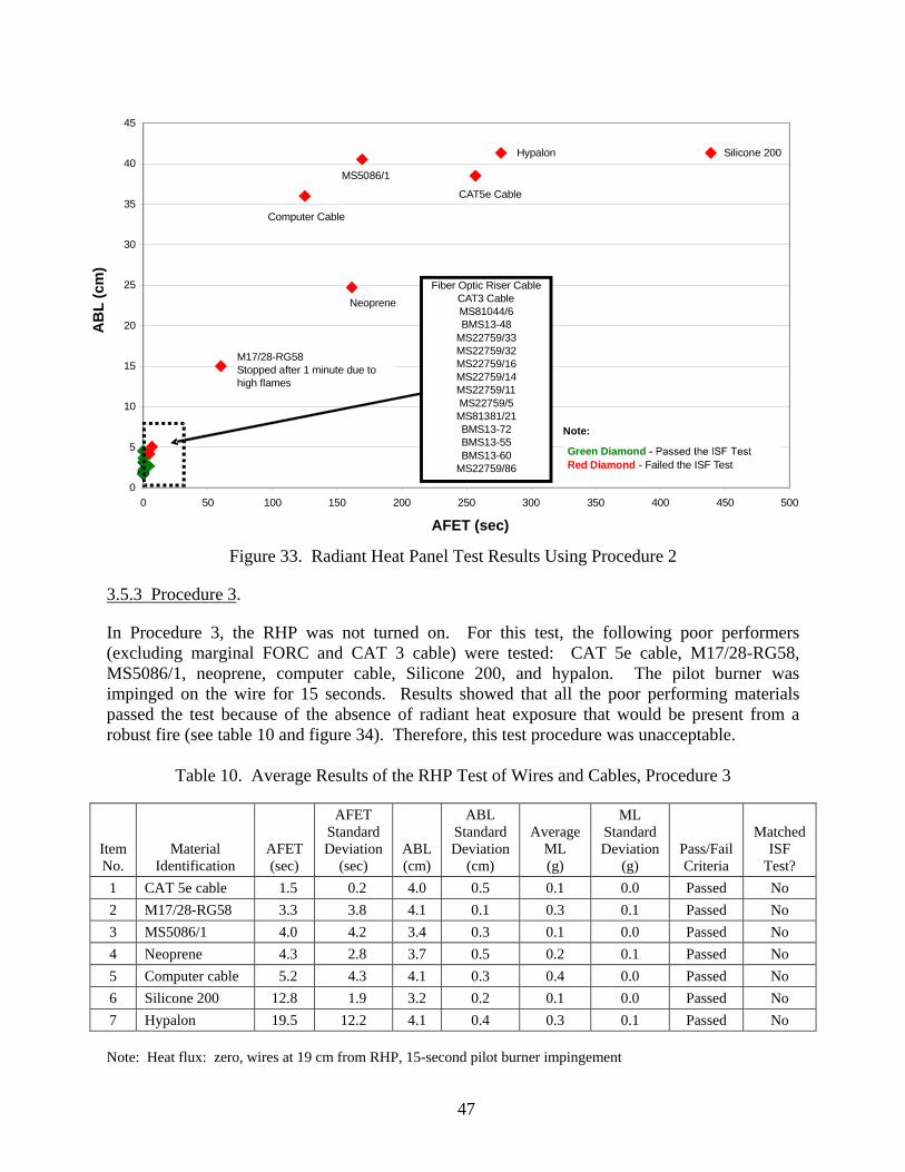
0
5
10
15
20
25
30
35
40
45
0 50 100 150 200 250 300 350 400 450 500
Average Flam Time (sec)
Ave
ra
MS5086/1
Figure 33. Radiant Heat Panel Test Results Using Procedure 2
3.5.3 Procedure 3.
In Procedure 3, the RHP was not turned on. For this test, the following poor performers (excluding marginal FORC and CAT 3 cable) were tested: CAT 5e cable, M17/28-RG58, MS5086/1, neoprene, computer cable, Silicone 200, and hypalon. The pilot burner was impinged on the wire for 15 seconds. Results showed that all the poor performing materials passed the test because of the absence of radiant heat exposure that would be present from a robust fire (see table 10 and figure 34). Therefore, this test procedure was unacceptable.
Table 10. Average Results of the RHP Test of Wires and Cables, Procedure 3
Item No.
Material Identification
AFET (sec)
AFET Standard Deviation
(sec) ABL (cm)
ABL Standard Deviation
(cm)
Average ML (g)
ML Standard Deviation
(g) Pass/Fail Criteria
Matched ISF
Test? 1 CAT 5e cable 01.5 00.2 4.0 0.5 0.1 0.0 Passed No 2 M17/28-RG58 03.3 03.8 4.1 0.1 0.3 0.1 Passed No 3 MS5086/1 04.0 04.2 3.4 0.3 0.1 0.0 Passed No 4 Neoprene 04.3 02.8 3.7 0.5 0.2 0.1 Passed No 5 Computer cable 05.2 04.3 4.1 0.3 0.4 0.0 Passed No 6 Silicone 200 12.8 01.9 3.2 0.2 0.1 0.0 Passed No 7 Hypalon 19.5 12.2 4.1 0.4 0.3 0.1 Passed No Note: Heat flux: zero, wires at 19 cm from RHP, 15-second pilot burner impingement
e Extinguishing
geB
urn
Leng
th(c
m)
M17/28-RG58Stopped after 1 minute due to high flames
Neoprene
Computer Cable
CAT5e Cable
Hypalon Silicone 200
AB
L (c
m)
Fiber Optic Riser CableCAT3 CableMS81044/6BMS13-48
MS22759/33MS22759/32MS22759/16MS22759/14MS22759/11MS22759/5MS81381/21BMS13-72BMS13-5BMS13-6
MS22759/86
Note:50 Green Diamond
Red Diamond - Failed the ISF Test
AFET (sec)
47

Figure 34. Radiant Heat Panel Test Results Using Procedure 3
3.5.4 Procedure 4.
In Procedure 4, Procedure 2 was followed, but the distance between the RHP and the wire specimen was reduced to 7.62 cm, increasing the severity of exposure. The wire specimen was preheated for 1 minute and impinged with the pilot burner for 15 seconds. The results of this test procedure matched the results of the ISF test results (see table 11 and figure 35).
Table 11. Average Results of the RHP Test of Wires and Cables, Procedure 4
Item No. Material
AFET (sec)
AFET Standard Deviation
(sec) ABL (cm)
ABL Standard Deviation
(cm)
Average ML (g)
ML Standard Deviation
(g) Pass/Fail Criteria
Matched ISF
Test? 1 MS22759/5 0.0 0.0 1.5 0.2 0.1 0.1 Passed Yes 2 MS81381/21 0.0 0.0 1.7 0.2 0.0 0.0 Passed Yes 3 MS22759/11 0.0 0.0 1.8 0.1 0.0 0.1 Passed Yes 4 MS22759/86 0.0 0.0 1.9 0.2 0.0 0.0 Passed Yes 5 BMS13-60 0.0 0.0 1.9 0.1 0.0 0.0 Passed Yes 6 BMS13-55 0.0 0.0 2.2 0.1 0.0 0.0 Passed Yes 7 MS22759/16 0.0 0.0 2.5 0.2 0.1 0.0 Passed Yes 8 BMS13-72 0.0 0.0 2.7 0.6 0.1 0.0 Passed Yes 9 MS22759/14 0.0 0.0 3.1 0.4 0.1 0.0 Passed Yes
10 BMS13-48 0.0 0.0 3.4 1.2 0.0 0.0 Passed Yes 11 MS22759/33 0.0 0.0 3.7 0.3 0.0 0.1 Passed Yes 12 MS22759/32 0.0 0.0 4.3 0.4 0.0 0.0 Passed Yes
0
5
10
15
20
25
30
35
40
45
0 50 100 150 200 250 300 350 400 450 500
Average Flame E (sec)
nLe
ngth
(cm
)
xtinguishing Time
Ave
rage
Bur
AB
L (c
m)
CAT5e CableM17/28-RG58
M5086/1Neoprene
Computer CableSilicone 200
Hypalon
Note:
Green DiamondRed Diamond - Failed the ISF Test
AFET (sec)
48

Table 11. Average Results of the RHP Test of Wires and Cables, Procedure 4 (Continued)
Item No. Material
AFET (sec)
AFET Standard Deviation
(sec) ABL (cm)
ABL Standard Deviation
(cm)
Average ML (g)
ML Standard Deviation
(g) Pass/Fail Criteria
Matched ISF
Test? 13 CAT 3 cable 4.0 3.6 30.0 N/A 2.4 0.3 Failed Yes 14 MS81044/6 4.3 2.5 2.9 0.1 0.1 0.1 Passed Yes 15 FORC 30.3 0.6 34.6 6.5 2.6 0.2 Failed Yes 16 MS5086/1 81.3 11.6 52.2 1.9 1.7 0.1 Failed Yes 17 Computer cable 117.0 7.5 45.8 0.2 7.1 0.5 Failed Yes 18 Hypalon 134.7 2.1 50.3 1.6 7.0 0.1 Failed Yes 19 Neoprene 157.7 14.0 45.3 2.0 3.6 0.2 Failed Yes 20 CAT 5e cable 183.0 16.5 48.7 0.8 5.9 0.1 Failed Yes 21 M17/28-RG58 205.7 35.3 54.1 1.9 8.9 0.4 Failed Yes 22 Silicone 200 394.3 54.6 58.1 0.7 3.5 0.1 Failed Yes
Note: Heat flux: 1.7 W/cm2, wires at 7.62 cm from RHP, 1-minute exposure, 15-second pilot burner impingement
0
10
20
30
40
50
60
70
0 50 100 150 200 250 300 350 400 450 500
Average F ing Time (sec)
Ave
rh
(cm
)
Silicone 200MS5086/1 M17/28-RG58Hypalon
Figure 35. Radiant Heat Panel Test Results Using Procedure 4
Part of the evaluation activities was to test smaller- (24-AWG) and larger-gauge (10-AWG) wire sizes to determine the impact on the results. Unfortunately, during this test procedure, the smaller-gauge wire broke during the pilot burner impingement within 5 seconds. Therefore, this test procedure was also unacceptable.
lame Extinguish
age
Bur
nLe
ngt
AB
L (c
m)
CAT5e Cable
NeopreneComputer Cable
Aviation Wires:MS81044/6MS22759/32MS22759/33BMS13-48
MS22759/14BMS13-72
MS22759/16BMS13-55BMS13-60MS22729
MS22759/11MS81381/21MS22759/5
Fiber Optic Riser CableFORC
CAT3 Cable
Note:
Green DiamondRed Diamond - Failed the ISF Test
AFET (sec)
49

50
3.5.5 Procedure 5.
In Procedure 5, a horizontal-mounting setup was evaluated. This position provided a heat flux gradient across the length of the wire or cable. Marginal materials, MS81044/6, CAT 3 cable, and FORC, and poor performing wires, Hypalon and M17/28-RG58, were tested to evaluate this mounting orientation. The wire specimen was preheated for 1 minute, and then impinged for 15 seconds with the pilot burner. The poor performing wires failed, but MS81044/6, FORC, and CAT 3 cable passed, making this test procedure unacceptable (see table 12 and figure 36).
Table 12. Average Results of the RHP Test of Wires and Cables, Procedure 5
Item No. Material
AFET (sec)
AFET Standard Deviation
(sec) ABL (cm)
ABL Standard Deviation
(cm)
Average ML (g)
ML Standard Deviation
(g) Pass/Fail Criteria
Matched ISF
Test? 1 MS81044/6 001.3 001.2 02.3 00.3 0.1 0 Passed Yes 2 CAT 3 cable 001.7 001.2 03.9 01.3 0.8 0.1 Passed No 3 FORC 001.8 000.8 05.7 01.0 0 0 Passed No 4 Hypalon 145.6 172.2 14.7 12.4 N/A N/A Failed Yes 5 M17/28-RG58 259.5 009.2 28.0 00.0 N/A N/A Failed Yes
Note: Heat flux: 1.7 W/cm2, wires are horizontal, 30 degrees from RHP (gradient), 1-minute exposure, 15-second pilot burner impingement

0
5
10
15
20
25
30
35
40
45
0 50 100 150 200 250 300 350 400 450 500
Average Fl
51
ame Extinguishing Time (sec)
Ave
rage
Bur
nLe
ngth
(cm
)A
BL
(cm
)
M17/28-RG58
Hypalon
Fiber Optic Riser CableCAT3 CableMS81044/6
Note:Green Diamond
Red Diamond - Failed the ISF Test
AFET (sec)
Figure 36. Radiant Heat Panel Test Results Using Procedure 5
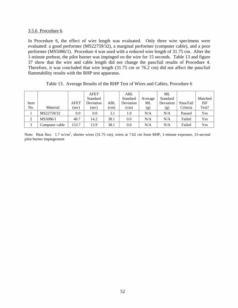
3.5.6 Procedure 6.
In Procedure 6, the effect of wire length was evaluated. Only three wire specimens were evaluated: a good performer (MS22759/32), a marginal performer (computer cable), and a poor performer (MS5086/1). Procedure 4 was used with a reduced wire length of 31.75 cm. After the 1-minute preheat, the pilot burner was impinged on the wire for 15 seconds. Table 13 and figure 37 show that the wire and cable length did not change the pass/fail results of Procedure 4. Therefore, it was concluded that wire length (31.75 cm or 76.2 cm) did not affect the pass/fail flammability results with the RHP test apparatus.
Table 13. Average Results of the RHP Test of Wires and Cables, Procedure 6
Item No. Material
AFET (sec)
AFET Standard Deviation
(sec) ABL (cm)
ABL Standard Deviation
(cm)
Average ML (g)
ML Standard Deviation
(g) Pass/Fail Criteria
Matched ISF
Test? 1 MS22759/32 000.0 00.0 03.1 1.0 N/A N/A Passed Yes 2 MS5086/1 040.7 14.2 38.1 0.0 N/A N/A Failed Yes 3 Computer cable 153.7 13.9 38.1 0.0 N/A N/A Failed Yes
Note: Heat flux: 1.7 w/cm2, shorter wires (31.75 cm), wires at 7.62 cm from RHP, 1-minute exposure, 15-second pilot burner impingement
52

0
5
10
15
20
25
30
35
40
45
0 50 100 150 200 250 300 350 400 450 500
Average Flam hing Time (sec)
Ave
ra
MS5086/1 Computer Cable
)cm(
53
Figure 37. Radiant Heat Panel Test Results Using Procedure 6
e Extinguis
geB
urn
Leng
thA
BL
(cm
)
Note:Green Diamond
Red Diamond - Failed the ISF TestMS22759/32
AFET (sec)

3.5.7 Procedure 7.
In Procedure 7, Procedure 4 was evaluated with different wire gauge sizes, including 24 AWG and 10 AWG. Unfortunately, the smaller-gauge (24-AWG) wire broke within 5 seconds during the pilot impingement, making this test procedure unacceptable. 3.5.8 Procedure 8.
Procedure 8 was identical to Procedure 7, but the impingement time was reduced to 3 seconds. Different wire gauge sizes were evaluated, which included 24, 20, 18, and 10 AWG. The wire specimen was preheated for 1 minute, and then impinged with the pilot burner for 3 seconds. With this procedure, the test results (see table 14) of all the wires and cables, including different gauge sizes, matched the results of the ISF test results (figure 38). Therefore, this was an acceptable test procedure.
Table 14. Average Results of the RHP Test of Wires and Cables, Procedure 8
Item No. Material
AFET (sec)
AFET Standard Deviation
(sec) ABL (cm)
ABL Standard Deviation
(cm)
Average ML (g)
ML Standard Deviation
(g) Pass/Fail Criteria
Matched ISF
Test? 1 MS22759/5 (20 AWG) 0v0.0 00.0 00.0 0.0 00.0 0.0 Passed Yes 2 MS22759/86 (20 AWG) 000.0 00.0 01.1 0.2 00.0 0.0 Passed Yes 3 MS22759/11 (24 AWG) 000.0 00.0 01.3 0.1 00.0 0.0 Passed Yes 4 BMS13-60 (20 AWG) 000.0 00.0 01.3 0.2 00.0 0.0 Passed Yes 5 BMS13-55 (20 AWG) 000.0 00.0 01.4 0.2 00.0 0.0 Passed Yes 6 MS22759/11 (20 AWG) 000.0 00.0 01.4 0.1 00.0 0.0 Passed Yes 7 MS81381/21 (20 AWG) 000.0 00.0 01.6 0.0 00.0 0.0 Passed Yes 8 MS22759/14 (20 AWG) 000.0 00.0 02.0 0.1 00.4 0.6 Passed Yes 9 BMS13-72 000.0 00.0 02.4 0.1 00.1 0.0 Passed Yes 10 BMS13-48 (20 AWG) 000.0 00.0 02.7 0.1 00.0 0.0 Passed Yes 11 MS22759/33 (24 AWG) 000.3 00.6 02.3 0.6 00.0 0.0 Passed Yes 12 MS22759/32 (20 AWG) 001.7 01.5 02.3 0.4 00.0 0.0 Passed Yes 13 MS22759/16 (20 AWG) 001.7 00.6 02.4 0.4 00.0 0.0 Passed Yes 14 MS22759/33 (20 AWG) 002.0 01.0 02.6 0.5 00.0 0.0 Passed Yes 15 CAT 3 cable 003.3 00.6 26.0 7.2 02.5 0.3 Failed Yes 16 MS81044/6 (20 AWG) 010.0 08.0 02.7 0.5 00.1 0.0 Passed Yes 17 FORC 027.0 10.4 41.3 4.4 02.3 0.5 Failed Yes 18 Computer cable 097.7 05.8 47.1 0.7 08.9 0.1 Failed Yes 19 MS5086/1 (20 AWG) 098.7 13.6 52.6 1.6 01.7 0.2 Failed Yes 20 MS5086/1 (10 AWG) 129.7 20.3 49.4 2.3 04.4 0.3 Failed Yes 21 Neoprene (18 AWG) 133.7 04.0 42.9 0.5 03.3 0.0 Failed Yes 22 Hypalon (18 AWG) 173.3 11.4 51.2 1.1 06.9 0.2 Failed Yes 23 CAT 5e cable 189.3 23.7 50.8 1.2 06.0 0.2 Failed Yes 24 Hypalon (10 AWG) 202.0 02.0 47.2 0.7 10.5 0.3 Failed Yes 25 M17/28-RG58 270.7 11.4 54.3 2.1 08.9 0.1 Failed Yes 26 Silicone 200 (20 AWG) 398.7 14.6 57.6 0.4 03.5 0.1 Failed Yes
Note: Heat flux: 1.7 W/cm2, wires at 7.62 cm from RHP, 1-minute exposure, 3-second pilot burner impingement
54

0
10
20
30
40
50
60
70
0 50 100 150 200 250 300 350 400 450 500
Average Flame g Time (sec)
Ave
ra
Silicone 200MS5086/1 Hypalon M17/28-RG58
CAT5e Cable
Computer Cable)cm
55
Figure 38. Radiant Heat Panel Test Results Using Procedure 8
Extinguishin
geB
urn
Leng
th(
AB
L (c
m)
Neoprene
Fiber Optic Riser CableAVIATION WIRES
MS81044/6MS22759/32MS22759/33BMS13-48
MS22759/14BMS13-72
MS22759/16BMS13-55BMS13-60
MS22759/86MSS22759/11MS81381/21MS22759/5
CAT3 Cable
Note:Green Diamond
Red Diamond - Failed the ISF Test
AFET (sec)

3.5.9 Procedure 9.
In Procedure 9, the effect of not preheating the wire specimens was again evaluated. The RHP was turned on, but the specimens were not heat soaked. Only two poor performing specimens were used: CAT 3 cable and computer cable. The pilot burner was impinged on the nonpreheated wire for 3 seconds. As shown in table 15 and figure 39, the results were inconsistent with the ISF tests; therefore, this test procedure was unacceptable.
Table 15. Average Results of the RHP Test of Wires and Cables, Procedure 9
Item No. Material
AFET (sec)
AFET Standard Deviation
(sec) ABL (cm)
ABL Standard Deviation
(cm)
Average ML (g)
ML Standard Deviation
(g) Pass/Fail Criteria
Matched ISF
Test? 1 CAT 3 cable 1.0 0.0 2.8 0.2 0.1 0.1 Passed No 2 Computer cable 2.7 1.2 3.8 2.2 0.3 0.3 Passed No
Note: Heat flux: 1.7 W/cm2, wires at 7.62 cm from RHP, 0-minute exposure, 3-second pilot burner impingement
56

0
5
10
15
20
25
30
35
40
45
0 50 100 150 200 250 300 350 400 450 500
Average Fla hing Time (sec)
Ave
racm
)(
57
Figure 39. Radiant Heat Panel Test Results Using Procedure 9
me Extinguis
geB
urn
Leng
thA
BL
(cm
)
CAT3 CableComputer Cable Note:
Green DiamondRed Diamond
AFET (sec)
- Failed the ISF Test

3.5.10 Procedure 10.
Procedure 10 was similar to Procedure 8, but the specimen length was reduced to 31.8 cm, and the wires were bundled (figure 40). The wire bundle was approximately 1.27 cm in diameter. The test results (table 16) of all the bundled-wire specimens matched the ISF test results (figure 41). By bundling the wires, there was greater discrimination between the fire-worthy and non-fire-worthy materials, because of the fire load and other effects, such as radiation interaction and contact flames between the wires in the bundle. Bundling promoted combustion of the non-fire-worthy wires but had no impact on the superior performance of the fire-worthy wires (figures 42 and 43).
Figure 40. The 30-Degree RHP Test Bundled-Wire Holder, Procedure 10
58
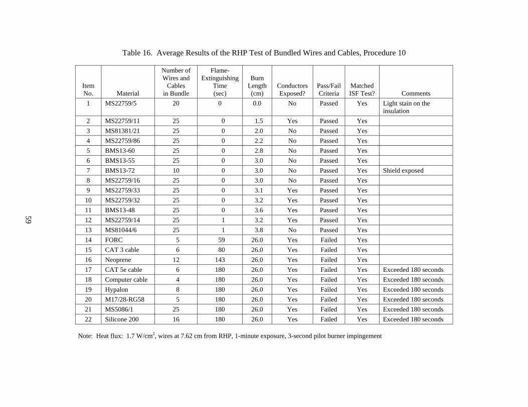
Table 16. Average Results of the RHP Test of Bundled Wires and Cables, Procedure 10
Item No. Material
Number of Wires and
Cables in Bundle
Flame- Extinguishing
Time (sec)
Burn Length(cm)
Conductors Exposed?
Pass/Fail Criteria
MatchedISF Test? Comments
1 MS22759/5 20 0 0.0 No Passed Yes Light stain on the insulation
2 MS22759/11 25 000 01.5 Yes Passed Yes 3 MS81381/21 25 000 02.0 No Passed Yes 4 MS22759/86 25 000 02.2 No Passed Yes 5 BMS13-60 25 000 02.8 No Passed Yes 6 BMS13-55 25 000 03.0 No Passed Yes 7 BMS13-72 10 000 03.0 No Passed Yes Shield exposed 8 MS22759/16 25 000 03.0 No Passed Yes 9 MS22759/33 25 000 03.1 Yes Passed Yes
10 MS22759/32 25 000 03.2 Yes Passed Yes 11 BMS13-48 25 000 03.6 Yes Passed Yes 12 MS22759/14 25 001 03.2 Yes Passed Yes 13 MS81044/6 25 001 03.8 No Passed Yes 14 FORC 05 059 26.0 Yes Failed Yes 15 CAT 3 cable 06 080 26.0 Yes Failed Yes 16 Neoprene 12 143 26.0 Yes Failed Yes 17 CAT 5e cable 06 180 26.0 Yes Failed Yes Exceeded 180 seconds 18 Computer cable 04 180 26.0 Yes Failed Yes Exceeded 180 seconds 19 Hypalon 08 180 26.0 Yes Failed Yes Exceeded 180 seconds 20 M17/28-RG58 05 180 26.0 Yes Failed Yes Exceeded 180 seconds 21 MS5086/1 25 180 26.0 Yes Failed Yes Exceeded 180 seconds 22 Silicone 200 16 180 26.0 Yes Failed Yes Exceeded 180 seconds
59
Note: Heat flux: 1.7 W/cm2, wires at 7.62 cm from RHP, 1-minute exposure, 3-second pilot burner impingement

0
5
10
15
20
25
30
0 20 40 60 80 100 120 140 160 180 200
Bur
nLe
n
60
Figure 41. Radiant Heat Panel Tests Results of Bundled Wires and Cables Using Procedure 10
gth
(cm
) Aviation-Grade Wires:
MS81044/6MS22759/14BMS13-48
MS22759/32MS22759/33MS22759/16BMS13-72BMS13-55BMS13-60MS22759/5
MS22759/86MS81381/21MS22759/11
Fiber Optic Riser Cable
CAT3 Cable NeopreneThese cables burned more than 180 seconds:
CAT5e CableComputer CableHypalonM17/28-RG58MS5086/1Silicone 200
Flame-Extinguishing Time (sec)

Figure 42. Posttest Fire-Worthy Insulation Specimens (Bundled)
Figure 43. Posttest Non-Fire-Worthy Insulation and Jacket Material Specimens (Bundled)
61

62
Wire bundle sleeves were also tested with this procedure. The wire bundle sleeves included expandable polyester sleeves (small and large diameters), silicone/Kevlar sleeves (with and without FR), heat shrink NTFR-1/4-0-SP, heat shrink NTFR-3/16-0-SP, heat shrink NO324-1-F6, heat shrink NO324-2-F6, Roundit 2000NX (Nomex/PPS), and Roundit 2000NX HT (Nomex/PEEK). The expandable polyester sleeves, silicone/Kevlar (FR), the Roundit 2000 NX, and the Roundit 2000NX HT passed the test. The small expandable polyester sleeves passed because they melted away during the 1-minute preheating period and no material was available as fuel when the pilot was impinged. The specimens with the heat shrink failed. Table 17 lists the results, and figure 44 shows the wire bundle sleeves.
Table 17. Average Results of the RHP Test of Wire Bundle Sleeves Using Procedure 10
Item No. Material
AFET (sec)
AFET Standard Deviation
(sec) ABL(cm)
ABL Standard Deviation
(cm) Pass/Fail Criteria Comments
1 Expandable polyester sleeve (smaller sample with wire inside)
003.0 N/A N/A N/A Passed The material melted and broke apart during the heat soak period. It did not contribute to the fire propagation.
2 Expandable polyester sleeve (larger sample with wire inside)
025.3 17.6 05.8 00.7 Passed
3 Silicone/Kevlar (FR) sleeve
021.5 03.5 05.3 00.6 Passed
4 NTFR-1/4-0-SP 022.0 N/A 05.1 N/A Passed The heat shrink melted to the bottom, and the wires were exposed, reducing fire propagation.
5 NO324-2-F6 069.0 29.7 33.7 15.6 Failed 6 NO324-1-F6 070.0 04.2 43.8 00.1 Failed 7 Silicone sleeve 325.0 N/A >40 N/A Failed 8 NTFR-3/16-0-SP 330.0 N/A 40.0 N/A Failed 9 Nomex/PPS
Roundit 2000 NX 003.3 03.2 06.6 00.7 Passed
10 Nomex/PEEK Roundit 2000NX HT
001.0 00.0 05.1 00.0 Passed
N/A = Not available Note: Heat flux: 1.7 W/cm2, wires at 7.62 cm from RHP, 1-minute exposure, 3-second pilot burner impingement

Rou
ndit
2000
NX
HT
(Pos
ttest
)
Rou
ndit
2000
NX
(Pos
ttest
)
Silic
one/
Kev
lar (
FR)
(Pos
ttest
)
Expa
ndab
le P
olye
ster
(Lar
ge, P
ostte
st)
Expa
ndab
le P
olye
ster
(Sm
all,
Pret
est)
NO
324-
1-F6
(Pos
ttest
)
NTF
R-3
/16-
0-SP
(p
rete
st)
NTF
R-3
/16-
0-SP
(p
ostte
st)
Figure 44. Wire Bundle Sleeves (Pretest and Posttest)
This procedure, using the bundled-wire specimen, is an improved test method to replace the Bunsen burner test for electrical wires (see appendix A for the complete test method details). 3.6 IMPROVED 30-DEGREE RHP TEST VERIFICATION.
The objective of this project was to develop an improved fire test method that could replace the Bunsen burner test method to determine the flammability characteristics of aircraft electrical wiring. The details of this improved test method are found in appendix A. To verify this improved test procedure, the results of the Bunsen burner test and the improved 30-degree RHP test pass/fail criteria were compared with the ISF test pass/fail criteria. To discriminate between fire-worthy and non-fire-worthy materials, the pass/fail results must be consistent with the ISF test results. Table 18 shows a comparison between the results of the Bunsen burner test, the 30-degree RHP test, and the ISF tests. This table shows that 20 out of 22 specimens passed the Bunsen burner test, which was not observed during the ISF test. The ISF test showed that nine material specimens performed poorly because they either burned significantly, burned for a long period of time, or both when subjected to a robust aircraft cabin attic fire. In contrast, the 30-degree RHP test perfectly matched the pass/fail results of the ISF tests. All current aviation-grade wires and cables passed the RHP test criteria, and the other industry cables failed.
63

As shown in table 18, material specimens with low-temperature ratings (from 60° to 105°C) failed the ISF and RHP tests. These low-rated wires and cables included: CAT 3 cable, CAT 5e cable, computer cable, M17/28-RG58, neoprene, FORC, hypalon, and MS5086/1. The current aviation-grade wires and cables had a higher-temperature rating that ranged from 135° to 260°C. Silicone 200 had a 200°C high-temperature rating, but it failed all three tests. From this comparative analysis, it can be concluded that the improved 30-degree RHP test is a more discriminating test than the Bunsen burner test at predicting the flammability of aircraft electrical wires and cables when exposed to the standard, robust fire threat in a simulated narrow-body aircraft cabin attic.
Table 18. Acceptance Comparison Between Test Methods
Test Method
Item No. Wire
Wire and Cable
Temperature Rating
Bunsen Burner
Test ISF Test 30-Degree RHP Test
1 CAT 3 cable 60 Passed Failed Failed 2 CAT 5e cable 60 Passed Failed Failed 3 Computer cable 60 Passed Failed Failed 4 M17/28-RG58 80 Passed Failed Failed 5 Neoprene 90 Passed Failed Failed 6 FORC 105 Passed Failed Failed 7 Hypalon 105 Passed Failed Failed 8 MS5086/1 105 Failed Failed Failed 9 MS22759/14 135 Passed Passed Passed 10 BMS13-48 150 Passed Passed Passed 11 BMS13-60 150 Passed Passed Passed 12 MS22759/16 150 Passed Passed Passed 13 MS22759/32 150 Passed Passed Passed 14 MS81044/6 150 Passed Passed Passed 15 MS81381/21 150 Passed Passed Passed 16 BMS13-55 200 Passed Passed Passed 17 BMS13-72 200 Passed Passed Passed 18 MS22759/11 200 Passed Passed Passed 19 MS22759/33 200 Passed Passed Passed 20 MS22759/5 200 Passed Passed Passed 21 Silicone 200 200 Failed Failed Failed 22 MS22759/86 260 Passed Passed Passed
64

4. RESULTS AND CONCLUSIONS.
The following results and conclusions were reached after analyzing the fire test data: • The current Federal Aviation Administration (FAA)-required 60-degree Bunsen burner
single-wire flammability certification test was confirmed to lack the ability to consistently discriminate between fire-worthy electrical wire insulating materials and non-fire-worthy insulating materials. Wires and cables that passed the FAA certification test, failed the more realistic, intermediate-scale fire (ISF) test, which simulated a typical aircraft wiring installation, when subjected to a robust fire source. Some of these wires and cables had insulation material that released large amount of heat when burned.
• The small-scale fire test equipment used was the radiant heat panel (RHP) test apparatus,
which provided the necessary adjustable fire test heat sources and other test parameters. The adjustable fire test heat sources included the RHP and a propane pilot burner. After evaluating a number of different test procedures, a test method was developed that would adequately correlate with ISF test results and distinguish between fire-worthy and non-fire-worthy wiring materials.
• The RHP test conditions and procedures that correlated with the results of the ISF test
were as follows: (1) the RHP was calibrated to a heat flux of 1.7 W/cm2, (2) a single or bundled 38.1-cm-long wire specimen was installed on the wire-holding fixture at an angle of 30 degrees, (3) the wire specimen was separated 7.62 cm from the RHP, (4) the wire specimen was preheated for 1 minute, and (5) the pilot burner was impinged on the wire specimen for 3 seconds. The pass/fail criteria dictate that the after-flame extinguishing time must not exceed 30 seconds and the burn length must not exceed 7.62 cm.
• RHP test results demonstrated that no difference in flammability performance (pass/fail
criteria results) existed when the specimen length and wire gauge size were changed. • Wire bundling did not affect the results of the aviation-grade wires (fire-worthy), but the
burning and damage of the non-fire-worthy insulation materials was significantly increased. Some bundled-wire specimens burned differently when compared to a single-wire specimen. Although exposed to identical fire conditions, a bundled-wire specimen could amplify the results of the single-wire specimens because of the addition of more fuel (more insulation material) and the interaction between the burning wires within the bundle.
• Ten types of wire bundle protective sleeves were also tested with the 30-degree RHP
flammability test. These protective sleeves were easy to test and resulted in six specimens passing the test method criteria and four specimens failing.
• Test results showed that the insulation materials of the aviation-grade wires (excluding
MS5086/1) had desirable combustion properties evaluated in the microscale combustion calorimetry (MSCC). Aviation-grade wires exhibited high onset temperatures, high mass
65

66
decomposition temperatures, high combustion temperatures, low specific heat of combustion, and low heat release capacity. It was determined that insulation material would pass the ISF test and the improved RHP test for wires if it had the following properties:
- Mass loss onset temperature greater than 285ºC - Mass decomposition temperature greater than 400ºC - MSCC onset temperature greater than 335°C - Combustion temperature greater than 485°C - Specific heat of combustion of specimen gases lower than 21 kJ/g - Heat release capacity lower than 375 J/g-K
These fire-worthy insulation materials included fluorinated ethylene propylene, polyvinylidene fluoride, ethylene-tetrafluoroethylene (including cross-linked), polytetrafluoroethylene, impregnated inorganic fibers, polyalkene, polyimide, and tetrafluoroethylene. 5. REFERENCES.
1. Federal Aviation Administration, Title 14 Code of Federal Regulations Part 25.856(a), Thermal Acoustic Insulation Materials.
2. Reinhardt, J., “Development of an Improved Fire Test Method for Aircraft Ducting
Materials,” FAA report DOT/FAA/AR-08/4, February 2008, pp. 32. 3. Federal Aviation Administration, Title 14 Code of Federal Regulations Part 25.1713, Fire
Protection: EWIS, revised as of May 18, 2009. 4. Federal Aviation Administration, Aircraft Materials Fire Test Handbook, FAA report
DOT/FAA/AR-00/12, Chapter 4: 60-Degree Bunsen Burner Test for Electric Wire, April 2000.
5. SAE International Aerospace Standards AS4373 Test Methods for Insulated Electric
Wire, “Method 801—Flammability,” Warrendale, Pennsylvania, 2003. 6. SAE International Aerospace Standards AS4372C Performance Requirements for Wire,
Electric, Insulated Copper or Copper Alloy, Section 3.8.1 Flammability, Warrendale, Pennsylvania, 2003.
7. SAE Aerospace Recommended Practices ARP4404B, Aircraft Electrical Installations,
Section 9.2.5 Flame Resistance of Wire Insulation, Warrendale, Pennsylvania, 2003. 8. Hirschler, M., ASTM STP 1376, Electrical Insulating Materials, “Fire Testing of
Electrical Materials,” ASTM International, West Conshohocken, Pennsylvania, 2000. (www.astm.org)
9. ASTM International Website: http://www.astm.org/DATABASE.CART/WITHDRAWN
/F777.htm

10. Cahill, P., “An Evaluation of the Flammability of Aircraft Wiring,” FAA report DOT/FAA/AR-TN04/32, December 2004, pp. 31.
11. Hirschler, M., “Fire Testing of Electrical Cables for Public Transportation,” GBH
International, Mill Valley, California, 2000. 12. Leoni, A.G., Cable Fire Protection, Flammability Tests on Ship and Offshore Cables,
2008. 13. ASTM Standard D 7309-07, “Standard Test Method for Determining Flammability
Characteristcics of Plastics and Other Solid Materials Using Microscale Combustion Calorimetry,” ASTM International, West Conshohocken, Pennsylvania, 2007, DOI: 10.1520/D7309-07. (www.astm.org)
14. ASTM E 2550-07, “Standard Test Method for Thermal Stability by Thermogravimetry,”
ASTM International, West Conshohocken, Pennsylvania, 2007. (www.astm.org)
67/68

APPENDIX A―FLAMMABILITY TEST METHOD AND CRITERIA FOR AIRCRAFT ELECTRICAL WIRING
A.1 SCOPE. This test method is intended to determine the flammability characteristics of aircraft electrical wire insulation and materials used to provide additional protection to wires and cables. A.2 DEFINITIONS. A.2.1 IGNITION TIME. Ignition time is the length of time the pilot flame is applied to the specimen. The ignition time for this test is 3 seconds. A.2.2 AFTER-FLAME EXTINGUISHING TIME. The after-flame extinguishing time is the number of seconds the specimen continues to flame after the pilot burner is removed from the specimen. Surface burning that results in a glow, but not in a flame, is not included. A.2.3 BURN LENGTH. Burn length is the length of damage along the wire bundle, both above and below the point of pilot burner impingement, due to that area’s combustion, including areas of partial consumption, charring, or embrittlement, but not including sooted, stained, warped, shrunk, or discolored areas. A.3 TEST APPARATUS. A.3.1 RADIANT HEAT PANEL TEST CHAMBER. Tests are conducted in a radiant heat panel (RHP) test chamber (see figure A-1). It is recommended that the test chamber be placed under an exhaust hood to facilitate clearing the chamber of smoke after each test. The RHP test chamber must be an enclosure 55 inches (1397 mm) long by 19.5 inches (495 mm) deep by 28 (710 mm) to 33 inches (762 mm) (maximum) above the test specimen; the tolerance of these dimensions is ±5%. The sides, ends, and top should be insulated with a fibrous ceramic insulation, such as refractory board Kaowool MTM board or 1260 Standard Board (manufactured by Thermal Ceramics and available in Europe). This board has an operating temperature of 2000°F (1093°C) and a maximum temperature rating of 2300°F (1260°C). On the front side, a suitable viewing window should be provided that is draft-free and made of high-temperature glass for viewing the sample during the tests; a 44″ x 6″ (111.8 by 15.2 cm) or larger viewing window has been found useful. A door should be provided below the window to access the movable specimen platform holder. The bottom of the test chamber must be a sliding steel platform that has a provision for securing the test specimen holder in a fixed and level position. The chamber must have an internal chimney
A-1

with exterior dimensions of 5.1 inches (129 mm) wide by 16.2 inches (411 mm) deep by 13 inches (330 mm) high at the opposite end of the chamber from the radiant energy source. The interior dimensions must be 4.5 inches (114 mm) wide by 15.6 inches (395 mm) long by 13 (330 mm) inches deep; the tolerance of these dimensions is 5%. The chimney must extend to the top of the chamber (see figure A-2).
Figure A-1. Radiant Heat Panel Test Chamber
Figure A-2. Internal Chimney
A-2

A.3.1.1 Radiant Heat Source. Mount the radiant heat energy source in a cast-iron frame or equivalent. An electric panel must have six, 3-inch (7.62-cm)-wide emitter strips. The emitter strips must be perpendicular to the length of the panel. The RHP must have a radiation surface of 13 by 18 7/8 inches, ±1/8 inch (330 by 480 mm, ±3 mm). The RHP must be capable of operating at temperatures up to 1300°F (704°C). An air propane panel must be made of a porous refractory material and have a radiation surface of 12 by 18 inches (305 by 457 mm). The RHP must be capable of operating at temperatures up to 1500°F (816°C). See figure A-3(a) and (b).
(a)
(b)
Figure A-3. (a) Electronic RHP and (b) Air Propane RHP
A-3

A.3.1.1.1 Electric Radiant Heat Panel. The electric RHP must be three-phase and operate at 208 volts (figure A-3(a)). A single-phase, 240-volt panel is also acceptable. An acceptable unit is part 10799-FAA assembled by Power Modules, Inc.; the RHPs are Raymax® 1330. A solid-state power controller and microprocessor-based controller are used to set the electric RHP operating parameters. A.3.1.1.2 Gas Radiant Heat Panel. Propane (liquid petroleum gas—2.1 UN 1075) is used for the RHP fuel (figure A-3(b)). The RHP fuel system must consist of a venturi-type aspirator for mixing gas and air at approximately standard atmospheric pressure. Suitable instrumentation for monitoring and controlling the flow of fuel and air to the RHP should be provided. An airflow gauge, an airflow regulator, and a gas pressure gauge should also be included.
A.3.1.2 Radiant Heat Panel Placement. The RHP is mounted in the chamber at 30° (±0.3°) to the horizontal specimen plane and 7.5 ±0.062 inches (19.05 ±0.15 cm) above the zero point of the sliding platform. A.3.2 SPECIMEN-HOLDING SYSTEM. The sliding platform serves as the housing for test specimen placement (see figure A-4). The dimensions shown in figure A-4 for the sliding platform may vary depending on the equipment purchased; these dimensions are not critical as long as the internal chamber dimensions (volume) are met. Some equipment manufacturers changed these dimensions to mount specimen holders and refractory boards. Place the refractory board on the sliding platform to create a horizontal surface. On this horizontal surface, place the specimen holder so the bundled-wire specimen is 3 ±1/16 (7.62 ±0.16 cm) inches away from the RHP and clears the propane pilot burner. It may be necessary to use multiple sheets of board material based on the height of the test specimen holder used (to meet the sample height requirement). Typically, these noncombustible sheets of material are available in 1/4-inch (6-mm) thicknesses. A sliding platform that is deeper than the 2-inch (50.8-mm) platform shown in figure A-4 is also acceptable as long as the sample height requirement is met.
A-4

Figure A-4. Sliding Platform
A 1/2-inch (13-mm) piece of refractory board, measuring 41 1/2 by 8 1/4 inches (1054 by 210 mm), should be attached to the back of the platform. The height of this board must not impede the sliding platform’s movement (in and out of the test chamber). If the platform has been fabricated such that the back side of the platform is high enough to prevent excess preheating of the specimen when the sliding platform is out, a retainer board is not necessary. A.3.2.1 Specimen Holder. The 15 ±0.125-inch (38.1 ±0.3 cm)-long bundled-wire specimen shall be tightly clamped on both ends with a specimen holder at a 30° ±0.3° angle from the horizon (see figure A-5). The specimen span between the lower clamp and upper clamp shall be 10 ±0.125 inches (25.4 ±0.3 cm) (see figure A-6). The specimen holder shall be mounted on the sliding platform so the perpendicular distance between the RHP and the upper surface of the specimen is 3 ±1/16 inches (7.62 ±0.16 cm) (see figure A-7).
A-5

Figure A-5. Specimen Holder
15 in (38.1 cm)
30
Wire Bundle
Specimen Holder
Refractory Board
8.5 in. (21.6 cm)
2 in. (5.1 cm)
Lace
10 in. (25.4 cm)
0.5 in (1.27 cm)
Figure A-6. Bundled-Wire Specimen Dimensions and Setup
A-6

3 in (7.62 cm)
30
Radiant Heat Panel
Wire Bundle
Specimen Holder
Refractory Board
Figure A-7. Bundled-Wire Specimen Mounting Inside RHP Test Apparatus A.3.3 PILOT BURNER. The propane pilot burner used to ignite the specimen must be a commercial propane torch with an axially symmetric burner tip and a propane supply venturi tube with an orifice diameter of 0.006 inch (0.15 mm). The length of the burner tube must be 2 7/8 inches (71 mm). The propane flow must be adjusted via gas pressure through an in-line regulator to produce a blue inner-cone length of 3/4 inch (19 mm). A 3/4-inch (19-mm) guide (such as a thin strip of metal) may be soldered to the top of the burner to aid in setting the flame height. The overall flame length must be approximately 5 inches long (127 mm). There should be a way to move the burner out of the ignition position so it is at least 1 inch (25.4 mm) above the wire specimen (see figure A-8).
Figure A-8. Propane Pilot Burner
A-7

A.3.4 THERMOCOUPLES. A 24-American Wire Gauge (AWG) Type K (chromel-alumel) thermocouple should be installed in the test chamber for temperature monitoring. It should be inserted into the chamber through a small hole drilled through the back of the chamber. The thermocouple should extend 11 inches (279 mm) out the back of the chamber wall, 11.5 inches (292 mm) from the right side of the chamber wall, and 2 inches (50.8 mm) below the RHP. The use of other thermocouples is optional. A.3.5 CALORIMETER. The calorimeter must be a 1-inch, cylindrical, water-cooled, total heat flux density, foil-type Gardon gauge that has a range of 0 to 5 Btu/ft2-second (0 to 5.7 watts/cm2). A.3.5.1 Calorimeter Calibration Specifications and Procedure. A.3.5.1.1 Calorimeter Specifications. • Foil diameter must be 0.25 ±0.005 inch (6.35 ±0.13 mm).
• Foil thickness must be 0.0005 ±0.0001 inch (0.013 ±0.0025 mm). • Foil material must be thermocouple-grade constantan. • Temperature measurement must be a copper constantan thermocouple. • The copper center-wire diameter must be 0.0005 inch (0.013 mm). • The entire face of the calorimeter must be lightly coated with Black Velvet™ paint,
having an emissivity of 96 or greater. A.3.5.1.2 Calorimeter Calibration. • The calibration method must be compared to a like-standardized transducer. • The standardized transducer must meet the specifications given in section A.3.5.1.1 of
this appendix. • The standard calorimeter must be calibrated against a primary standard traceable to the
National Institute of Standards and Technology. • The method of transfer must be a heated graphite plate. • The graphite plate must be electrically heated, have a clear surface area on each side of
the plate of at least 2 by 2 inches (51 by 50.8 mm), and be 1/8 inch ±1/16 inch thick (3.2 ±1.6 mm).
A-8

• The two transducers must be centered on opposite sides of the plate at equal distances from the plate.
• The distance from the calorimeter to the plate must be no less than 0.0625 inch (1.6 mm),
nor greater than 0.375 inch (9.5 mm). • The range used in calibration must be at least 0-3.5 Btu/ft2-second (0-3.9 watts/cm2) and
no greater than 0-5.7 Btu/ft2-second (0-6.4 watts/cm2). • The recording device must record the two transducers simultaneously. A.3.5.1.3 Calorimeter Fixture. With the sliding platform pulled out of the chamber, the calorimeter-holding frame is installed and a sheet of noncombustible material (refractory board) is placed in the bottom of the sliding platform adjacent to the holding frame; the calorimeter-holding frame may have a single calorimeter or multiple calorimeters (see figure A-9(a) and (b)). This will prevent heat loss during calibration. The calorimeter-holding frame dimensions can be of any size as long as the distance from the upper surface of the calorimeter to the RHP surface from the centerline of the first hole (“zero” position) is 7 1/2 ±1/8 inches (191 ±3 mm). There are two typical frame dimensions currently used by laboratories with this equipment: (1) 13.25 inches (336 mm) in length (front to back) by 8.5 inches (216 mm) in width and (2) 14 inches (356 mm) in length (front to back) by 7 inches (178 mm) in width. These frames must rest on top of the sliding platform, must be fabricated of 0.125-inch (3.2 mm) flat-stock steel, and have an opening that accommodates a 1/2-inch (12.7 mm)-thick piece of refractory board, which is level with the top of the sliding platform. For the multiple-calorimeter-holding frame, (1) the board must have three 1/2-inch (25.4 mm)-diameter holes drilled through the board for calorimeter insertion, (2) the distance between the centerline of the first hole to the centerline of the second hole must be 2 inches (50.8 mm), and (3) it must also be the same distance from the centerline of the second hole to the centerline of the third hole. If the single-calorimeter-holding frame is used, the frame must be moved in 2-inch (5.1-cm) intervals to verify the required heat fluxes. A calorimeter-holding frame that differs in construction is acceptable as long as the height from the centerline of the first hole to the RHP and the distance between holes is 2 inches (50.8 mm), as described above.
A-9

(a)
(b)
Figure A-9. (a) Single- and (b) Multiple-Calorimeter-Holding Frames
A.3.6 INSTRUMENTATION. A calibrated recording device with an appropriate range or a computerized data acquisition system must be provided to measure and record the outputs of the calorimeter and the thermocouple. The data acquisition system must be capable of recording the calorimeter output every second during the calibration.
A-10

A.3.7 TIMING DEVICE. A stopwatch or other timing device must be provided, accurate to ±1 second/hour, to measure the time of application of the pilot burner flame and the after-flame time. A.3.8 RULER. A ruler or scale, calibrated and graduated to the nearest 1/16 inch (1.58 mm), must be provided to measure the burn length. A.4 TEST SPECIMENS. Wire or cable bundles are the preferred test specimens, but certain situations may exist in which enough samples of the wire or cable are not available, or the wire gauge size is too large to bundle. In these cases, single-wire or -cable testing will be allowed. The minimum specimen length for this test is 4 inches (10.16 cm). Test specimens also include materials used to provide additional protection to wires and cables, such as sleeves and shrink wrap. A.4.1 SPECIMEN NUMBER. At least three specimens of each wire insulation and/or jacket type shall be prepared and tested. No additional tests are required if the wire gauge size is changed as long as the specimen (1)is tested in the bundled-wire configuration, (2) insulation material is the same, and (3) is from the same manufacturer. A.4.2 SPECIMEN LENGTH. The preferred specimen length is 15 ±0.125 inches (38.1 ±0.3 cm), but certain situations, such as testing shorter wire lengths inside electronic equipment, may exist. In these cases an extension may be used, such as an alligator clip connected to a bare wire, to obtain the preferred length. The specimen span between the lower clamp and upper clamp shall be approximately 10 ±0.125 inches (25.4 ±0.3 cm), see figure A-6. If a protective sleeve is to be tested, it should be cut to 9.25 ±0.125 inches (23.5 ±0.3 cm) long and wrapped around the 15-inch-long (1/2-inch-diameter) bundled-wire specimen or some other 1/2-inch-diameter, nonflammable core. The sleeve shall be located between the upper and lower clamp in such a way that it covers the wire bundle near the pilot burner area (see figure A-10); make sure that the upper surface of the protective sleeve is 3 ±1/16 inches (7.62 ±0.16 cm) away (parallel) from the RHP.
A-11

3 in. (7.62 cm)
30
Radiant Heat Panel
Wire Bundle
Specimen Holder
Refractory Board
Protective Sleeve(9.25 in, 23.5 cm, long)
Figure A-10. Protective Sleeve Specimen Mounting Inside RHP Test Apparatus If heat shrink is to be tested, it should be cut to the desired length, placed on the 15 ±0.125-inch (38.1 ±0.3-cm)-long fire-worthy wire or cable (at the pilot burner impingement point) and tested. A.4.3 SPECIMEN DIAMETER. The preferred specimen (wire bundle) diameter shall be approximately 0.5 inch (1.27 cm). The bundle should include as many wires or cables necessary until the diameter is approximately 0.5 inch (1.27 cm), and it should be secured with safety wire or other lacing material that will not melt or burn away during the test. A 1/2-inch-hole template is useful to determine the number of wires and cables in the bundle. The wire bundle must be homogeneous, that is, built with the same type of wire insulation. Two laces (or safety wire) are useful (and enough) to secure the wire bundle specimen. The lace (or safety wire) should be kept away from the pilot burner impingement point. The first lace (or safety wire) shall be placed approximately 2 inches (51 mm) from the lower part of the bundled-wire specimen and the second shall be 8.5 inches (216 mm) from the first lace (figure A-6). If the gauge of the wire or cable is very large and the bundling exceeds 0.5 inch (1.27 cm), the large-diameter single wire or cable should be used as the specimen. If the wire gauge is larger than 0.5 inch (1.27 cm), then a single wire shall be tested. If an insufficient number of wires is available to create the 0.5-inch (1.27-cm) wire bundle, then a single wire should be tested. The results of this single-wire test will apply only to wires with the same AWG size as the one tested.
A-12

A.5 CONDITIONING. Condition specimens at 70° ±5°F (21° ±3°C) and 50% ±5% relative humidity for 24 hours minimum. Only one specimen at a time should be removed from the conditioning environment immediately before testing. A.6 PROCEDURE. A.6.1 APPARATUS CALIBRATION. The following steps are used to calibrate the test apparatus. 1. With the sliding platform out of the chamber, the calorimeter-holding frame is installed.
The platform back is pushed into the chamber and the calorimeter is inserted into the first hole (“zero” position), see figure A-9. The bottom door, located below the sliding platform, is closed. At this point, the distance from the centerline of the calorimeter to the RHP surface must be 7 1/2 ±1/8 inches (191 ±3 mm). Prior to igniting the RHP, ensure that the calorimeter face is clean and that water is running through the calorimeter.
2. The RHP is turned on. Its power or fuel/air mixture should be adjusted to achieve
1.5 ±5% Btu/ft2-second (1.7 watts/cm2 ±5%) at the “zero” position. The unit must reach steady state (this may take up to 1 hour). The pilot burner must be off and in the down position during this time.
3. After steady-state conditions have been reached, the calorimeter is moved 2 inches
(50.8 mm) from the “zero” position (first hole) to position 1 and the heat flux is recorded. The calorimeter is moved to position 2 and the heat flux is recorded. At each position, time should be allotted for the calorimeter to stabilize. Table A-1 shows typical calibration values at the three positions.
4. The bottom door is opened and the calorimeter and holder fixture are removed. Caution
is necessary, as the fixture is very hot.
Table A-1. Calibration Table
Position Btu/ft2-sec Watts/cm2 Zero 1.5 ±5% 1.7 ±5% 1 1.5 ±5% 1.7 ±5% 2 1.43 ±5% 1.62 ±5%
A-13

A.6.2 TEST PROCEDURE. The test procedure is performed following these steps: 1. Before calibrating the RHP, at room temperature, mount the specimen holder on the
sliding platform so the perpendicular distance between the RHP and the upper surface of the specimen is 3 ±1/16 inches (7.62 ±0.16 cm) (see figure A-7). The distance between the base of the pilot burner flame and the specimen shall be approximately 1.5 inches (3.81 cm) (see figure A-11). The angle of impingement should be close to horizontal, but it may vary depending on the specimen—this slight angle variability will not affect results. The center of the pilot burner flame must impinge the wire at a distance of no more than 5 inches (12.7 cm) from the lower clamping point (see figure A-12). Mark or setup guides to identify the correct position of the specimen holder because it will be removed from the sliding platform for test equipment calibration and specimen changes.
2. Calibrate the RHP as described in section A.6.1. 3. Ignite the pilot burner. Ensure that it is at least 1 inch (25.4 mm) above the wire
specimen. The pilot burner should be above the wire specimen before the test begins. 4. Place the test specimen, mounted on the specimen holder, on the sliding platform.
Ensure the specimen holder is placed on the premarked location and secured. 5. Immediately push the sliding platform into the chamber and close the bottom door. 6. Quickly rotate the specimen holder arm, where the wire is mounted, 30 degrees so the
wire specimen is parallel to, and 3 inches (76.2 mm) from, the RPH. 7. Heat-soak the specimen for 1 minute. 8. After the 1-minute heat-soak, impinge the pilot burner flame on the specimen for 3
seconds (ignition time). Then remove to a position at least 1 inch (25.4 mm) above the specimen.
9. Wait 5 seconds after the flames self-extinguish to verify that it will not re-ignite.
Pilot Burner
~1.5 in.(3.8 cm) Wire Bundle
Figure A-11. Pilot Burner Depth Placement
A-14

A-15
Figure A-12. Pilot Burner Horizontal Placement A.7 REPORT. A.7.1 MATERIAL IDENTIFICATION. The wire and cable bundle tested should be fully identified. A.7.2 TEST RESULTS. A.7.2.1 After-Flame Time. The after-flame time for each specimen tested should be reported. The average value for flame time should be determined and recorded. A.7.2.2 Burn Length. The burn length for each specimen tested should be reported. The average value for burn length should be determined and recorded. A.7.2.3 Posttest Specimen Condition. Any shrinkage or melting of each of the tested specimens should be reported.

A.8 REQUIREMENTS. The following requirements apply to bundled-wire specimens and protective sleeve specimens. A.8.1 AFTER-FLAME EXTINGUISHING TIME. The average flame-extinguishing time for all the specimens tested shall not exceed 30 seconds. A.8.2 BURN LENGTH. The average burn length for all the specimens tested shall not exceed 3 inches (76 mm). A.8.3 WIRE BREAKAGE. It shall not be considered a failure if the wire breaks during the test.
A-16


![NCHRP Web Document 46: Improved Live Load Deflection Criteria … · NCHRP Web Document 46 (Project 20-7[133]): Contractor’s Final Report Improved Live Load Deflection Criteria](https://img.pdfslide.us/doc/110x75/5acf99db7f8b9ac1478cfd54/nchrp-web-document-46-improved-live-load-deflection-criteria-web-document-46.jpg)