Embed Size (px)
Citation preview
,....4//4Fe_.-,=,.2.16
Development of an Efficient CFD Model for Nuclear Thermal Thrust
Chamber Assembly Design
Gary Chang*, Yasushi Ito t, Doug Ross ¢
Department of Mechanical Engineering
University of Alabama at Birmingham, Birmingham, AL 35294-4461
Yen-Sen Chen§
Engineering Sciences, Inc., Huntsville, Alabama, 35815
Ten-See Wang**
NASA Marshall Space Flight Center, Huntsville, Alabama, 35812
Abstract
The objective of this effort is to develop an efficient and accurate computational
methodology to predict both detailed thermo-fluid environments and global
characteristics of the internal ballistics for a hypothetical solid-core nuclear thermal
thrust chamber assembly (NTTCA). Several numerical and multi-physics thermo-
fluid models, such as real fluid, chemically reacting, turbulence, conjugate heat
transfer, porosity, and power generation, were incorporated into an unstructured-
grid, pressure-based computational fluid dynamics solver as the underlying
computational methodology. The numerical simulations of detailed thermo-fluid
environment of a single flow element provide a mechanism to estimate the
thermal stress and possible occurrence of the mid-section corrosion of the solid
core. In addition, the numerical results of the detailed simulation were employed
to fine tune the porosity model mimic the pressure drop and thermal load of the
coolant flow through a single flow element. The use of the tuned porosity model
enables an efficient simulation of the entire NTTCA system, and evaluating its
performance during the design cycle.
I. Introduction
Nuclear thermal propulsion can carry far larger payloads and reduce travel time for
astronauts traveling to Mars and other planets of the solar system than any chemical propulsioncurrently available. One of the concepts that was extensively tested during the Rover/NERNA
era and appear to be the most feasible is the solid-core concept. I This concept involves a solid-
core reactor consisting of hundreds of heat generating solid flow elements, and each flow
element containing tens of flow channels through which the working fluid acquires energy and
expands in a high expansion nozzle to generate thrust. Hydrogen is most often chosen as the
propellant due to its low molecular weight. The solid-core reactor therefore resembles a heat
exchanger. To minimize the effect of its weight, the reactor often operates at very high
temperature and power density, which imposes real challenges to the integrity of the flow
*Associate Professor, Senior Member, AIAA. E-mail: [email protected]*Research Assistant Professor, Member AIAA
ProgrammerPresident, Member AIAA
**Technical Assistant, ER43, Thermal and Combustion Analysis Branch, Senior Member AIAA
https://ntrs.nasa.gov/search.jsp?R=20070031967 2018-08-30T18:05:51+00:00Z
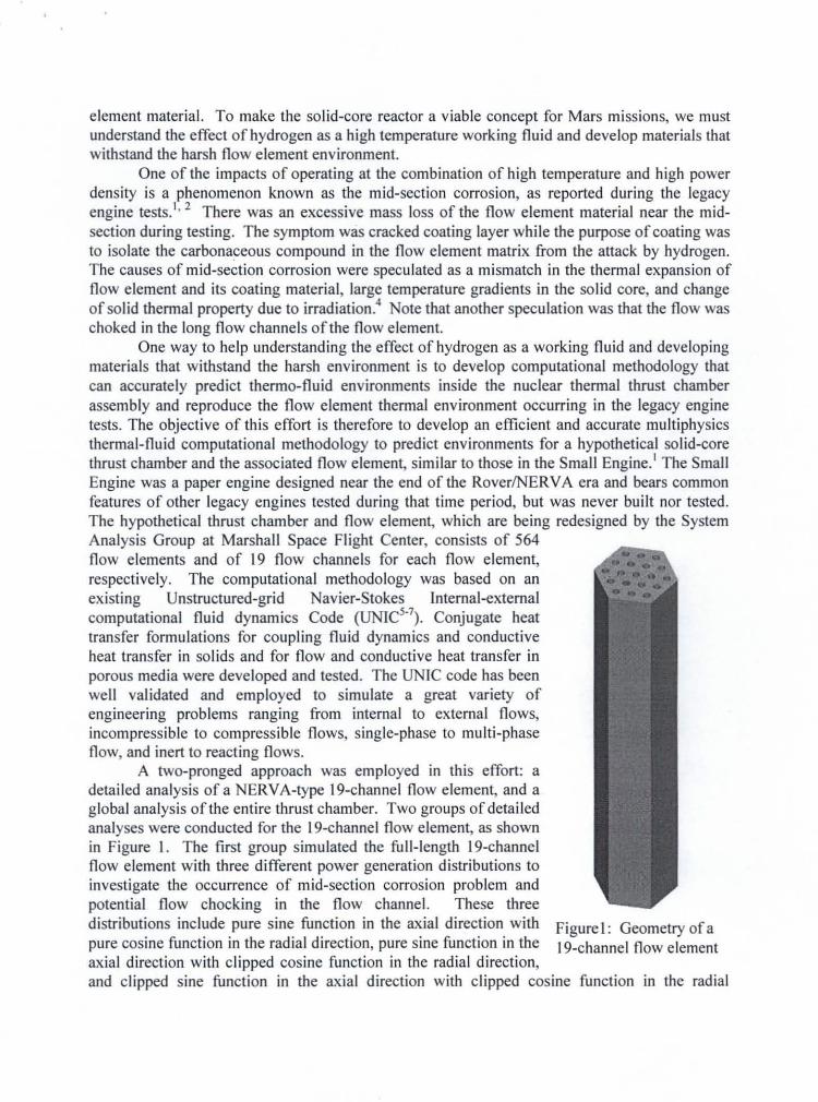
Figure I: Geometry of a19-channel flow element
:
element material. To make the solid-core reactor a viable concept for Mars missions, we mustunderstand the effect of hydrogen as a high temperature working fluid and develop materials thatwithstand the harsh flow element environment.
One of the impacts of operating at the combination of high temperature and high powerdensity is a phenomenon known as the mid-section corrosion, as reported during the legacyengine tests. l
• 2 There was an excessive mass loss of the flow element material near the midsection during testing. The symptom was cracked coating layer while the purpose of coating wasto isolate the carbonaceous compound in the flow element matrix from the attack by hydrogen.The causes of mid-section corrosion were speculated as a mismatch in the thermal expansion offlow element and its coating material, large temperature gradients in the solid core, and changeof solid thermal property due to irradiation' Note that another speculation was that the flow waschoked in the long flow channels of the flow element.
One way to help understanding the effect of hydrogen as a working fluid and developingmaterials that withstand the harsh environment is to develop computational methodology thatcan accurately predict thermo-fluid environments inside the nuclear thermal thrust chamberassembly and reproduce the flow element thermal environment occurring in the legacy enginetests. The objective of this effort is therefore to develop an efficient and accurate multiphysicsthermal-fluid computational methodology to predict environments for a hypothetical solid-corethrust chamber and the associated flow element, similar to those in the Small Engine.1 The SmallEngine was a paper engine designed near the end of the Rover/NERVA era and bears commonfeatures of other legacy engines tested during that time period, but was never built nor tested.The hypothetical thrust chamber and flow element, which are being redesigned by the SystemAnalysis Group at Marshall Space Flight Center, consists of 564flow elements and of 19 flow channels for each flow element,respectively. The computational methodology was based on anexisting Unstructured-grid Navier-Stokes Internal-externalcomputational fluid dynamics Code (UNICs.7). Conjugate heattransfer formulations for coupling fluid dynamics and conductiveheat transfer in solids and for flow and conductive heat transfer inporous media were developed and tested. The UNIC code has beenwell validated and employed to simulate a great variety ofengineering problems ranging from internal to external flows,incompressible to compressible flows, single-phase to multi-phaseflow, and inert to reacting flows.
A two-pronged approach was employed in this effort: adetailed analysis of a NERVA-type 19-channel flow element, and aglobal analysis of the entire thrust chamber. Two groups of detailedanalyses were conducted for the 19-channel flow element, as shownin Figure I. The first group simulated the full-length 19-channelflow element with three different power generation distributions toinvestigate the occurrence of mid-section corrosion problem andpotential flow chocking in the flow channel. These threedistributions include pure sine function in the axial direction withpure cosine function in the radial direction, pure sine function in theaxial direction with clipped cosine function in the radial direction,and clipped sine function in the axial direction with clipped cosine function in the radial
Z: " L] i'll ii! fl Z_L ............................ _"_--_ ......... _ ...... ]lllllllqllil Illml ..... ii ............. ll_ .... ' I .............................
direction. The second group simulated a one-eighth-length 19-channel flow element with
different side-wall temperature and flow channel diameters to obtain data for calibrating the
porosity model used in the global analysis of the entire thrust chamber. In the global thrust
chamber analysis, the 19-channels for each flow element were lumped together as a porous
media to save computational resources, and the core surrounding components such as the slats
and reflector were treated as heat conducting solids to provide accurate boundary condition for
the solid-core environment. The porosity model is employed to represent the effect of the
friction loss and heat transfer as the working fluid flowing through the flow element. The use of
the porosity model enables an efficient simulation of the entire thrust chamber, and evaluation of
its performance during the design cycle.
In order to support both the detailed and global analyses, several physical submodels wereeither improved or added into the UNIC code rag. These code improvements include: an anisotropic
drag and heat transfer porosity model to account for the directional effect of the flow channel, a
source term in the energy to model the power generation of the solid core with a user's specified
distributions, validation of the conjugate heat transfer capability built in the UNIC code with a well
known thermal analysis code, S1NDA 1° to provide an accurate calculation of heat transfer through
the solid-fluid interface. The tuned porosity model for the flow element and the numerical results of
both the detailed and global analyses are reported herein..
IL Numerical Methodology
A. Computational Fluid Dynamics
The employed CFD solver, UNIC, solves a set of Reynolds-averaged governing
equations (continuity, Navier-Stokes, energy, species mass fraction, etc.) to satisfy the
conservation laws for a turbulent flow of interest. The set of governing equation can be writtenin Cartesian tensor form:
°P + °-_-(pV.)=oOt 3xj
O(pV,) + 0 (pV, V,)3t 3xj "
=-@+ a(rj, +r,) + S vax_ axj
(1)
(2)
a(,,h,)±(o,,-,,,)-<" ", ] <uj,+,,),0,at axj ' at axjLkPr Pr,)OxjJ Oxj
a(pk)+ O_7(pVjk,= _V(i a _i_,u, ] ak 1 + p(I-[ -_') (4,at oxj Lk a_ ) axj j
at ox, oxj L\ ,7 ) axj d ,ck
a(,o,) ±F(e+,', (6)at o_, ax,LkS_ Sc,)a_,j
where p is the fluid density p is the pressure, _ = (u, v, w) stands for the velocity components in
x-, y-, and z-coordinates respectively, ht and h are the total and static enthalpies, k is the
turbulence kinetic energy, 11 and e are the production and dissipation rates of turbulence, at and
Si are the mass fracfion and production/destruction rate of i-th species, Qr is the radiative heat
flux, Sv and S h are the source/sink terms of the momentum and energy equations, ,u and/.tt are the
fluid and eddy viscosity, _i and rt are the viscous stress and Reynolds stress, Pr and Prt are thePrandtl and turbulent Prandtl numbers, Sc and Sct are Schmidt and turbulent Schmidt numbers,
C1, C2, Ca, crk, and or, are turbulence modeling constants. Detailed expressions for the k-c
models and wall functions can be found in [11]. An extended k-e turbulence model 12was used to
close the system of Reynolds-averaged governing equations. A modified wall function
approach13, 14was employed to provide wall boundary layer solutions that are less sensitive to
the near-wall grid spacing.
A predictor and multi-corrector pressure-based solution algorithm is' 16was employed in
the UNIC code to couple the set of goveming equations such that both compressible and
incompressible flows can be solved in a unified framework without using ad-hoc artificial
compressibility and/or a pre-conditioning method. The employed predictor-corrector solution
method s is based on modified pressure-velocity coupling approach of the SIMPLE-type 16
algorithm which includes the compressibility effects and is applicable to flows at all speeds. In
order to handle problems with complex geometries, the UNIC code employs a cell-centeredunstructured finite volume method 6' 7 to solve for the governing equations in the curvilinear
coordinates, in which the primary variables are the Cartesian velocity components, pressure,
total enthalpy, turbulence kinetic energy, turbulence dissipation and mass fractions of chemical
species.
The inviscid flux is evaluated through the values at the upwind cell and a linear
reconstruction procedure to achieve second order accuracy. A multi-dimensional linearreconstruction approach by Barth and Jespersen 17was used in the cell reconstruction to achieve
higher-order accuracy for the convection terms. A second-order central-difference scheme was
employed to discretize the diffusion fluxes and source terms. A dual-time sub-iteration method
is employed for time-accurate time-marching computations. A pressure damping term, Rhie and
Chow 18, is applied to the evaluation of mass flux at the cell interface to avoid the even-odd
decoupling of velocity and pressure fields. All the discretized governing equations are solved
using the preconditioned Bi-CGSTAB 19 matrix solver, except the pressure-correction equation
which has an option to be solved using GMRES 2° matrix solver when the matrix is ill-
conditioned. An algebraic multi-grid (AMG) solver 21 was included such that users can activate
to improve the convergence if desired. The UNIC code also has mesh refinement and coarsening
capabilities to improve the numerical accuracy and computational efficiency. In order to
efficiently simulate problems involving large numbers of meshes, the UNIC code employed
parallel computing with domain decomposition, where exchange of data between processors isdone by using MP122. Domain decomposition (partitioning the computational domain into
several sub-domains handled by different computer processors) can be accomplished by using23
METIS or a native partitioning routine in the UNIC code.
In addition, numerous submodels were incorporated in the UNIC code to model various
physics and transport phenomena. These submodels include: 1) finite-rate and equilibrium
chemistry for combustion, 2) conjugate heat transfer for coupling heat convection and
conduction, 3) both the heterogeneous spray model with Eulerian/Lagrangian approach and the
homogeneous spray model with the Eulerian/Eulerian approach and real-fluid property models
for liquidsprayflow,4) thefinitevolumemethodfor solvingradiationtransportequation(RTE),5) solvingtranslationalandvibrationalenergyequationsfor thermalnon-equilibriumeffect,6)porositymodelfor flow throughaporousmedia,etc. Duringthelastdecade,theUNIC codehasbeenimprovedto equipmodelsappropriateto resolvethe complexphysics,and hasbeenemployedto simulatea greatvarietyof engineeringproblems.TheresultshaveshownthattheUNIC codeis ascomputationallyefficientasanyCFDcodes.Hence,we employedtheUNICcodeandmodifiedit to accountfor somespecificeffectsof interestin thepresentstudy,suchaspowergeneration,non-isotropicporositywith or without heat conduction,variablethermalconductivitiesandspecificheatbasedondifferentsolidmaterialsandtemperatures.Someofthesecodeimprovementsperformedin thisstudyaredescribedin thefollowing.
B. Conjugate Heat Transfer:
The framework of conjugate heat transfer is to solve the heat transfer in the fluid flow
and the heat conduction in the solid in a coupled manner. The governing equation describing the
heat transfer in the fluid flow is shown in Eq. (3), where the heat conduction in the solid can bewritten as:
OpCpT 0 ( OT'_ OQs--|,c7-| = +-- (7)
8t ox, \ ox, ) 8x_
where Qv and Q, represent source terms from volumetric and boundary contributions,
respectively, r and Cp denote the thermal conductivity and capacity of the solid material,
respectively. In the case of simulating solid core with power generation, Qv depends on power
generation distributions function employed. In the present study, three power distribution
functions were examined: (i) pure sine function in the axial direction with pure cosine function
in the radial direction; (ii) pure sine function in the axial direction with clipped cosine function
in the radial direction; (iii) Clipped sine function in the axial direction with clipped cosine
function in the radial direction. The temperature value at the fluid-solid interface is obtained by
enforcing the heat flux continuity condition, i.e. Os = -qw where qw is the heat flux from the fluid
to the solid calculated by solving Eq. (3) including the turbulence effect if applicable. In order to
achieve numerical stability and enforce the heat flux continuity condition, an implicit treatment
of the temperature at the fluid-solid interface is employed. In this approach, Eq. (7) can bediscretized as
1 qw) (8)_pCp -_ -At Ay, t Ay,,
where the superscripts n+l and n denote the values at the next and current time levels,
respectively. To and Tc are the temperatures at the fluid-solid interface and at the center of the
solid cell next to the fluid-solid interface in respect, y, represents the normal distance from theinterface to the center of the solid cell next to the fluid-solid interface. The ½ factor on the left
hand side of the above equation is because only half of the solid cell is involved in the control
volume. It can be seen that this scheme can be applied to both transient and steady state
simulations. For steady-state simulations, an acceleration factor can be used to improve
convergence of heat conduction in the solid. Implementation of the implicit treatment has been
validated 9 by comparing with the SINDA code.
C. Porosity Model:
............................ ........................................ i][] I[Ir_ _,,",
In the present study, a porosity model was developed to represent the momentum and
energy transport through an assembly of flow pipes, and the heat conduction through the solid
material within a flow element. Hence, the porosity model will include separate temperatures
and thermal conductivities for both the solid material and fluid flow. The momentum and energy
equations for the fluid flow are the same as Eqs. 2 & 3, except the source terms will be modifiedto account for the extra friction loss and heat transfer. The source term of the momentum
equation (Eq. 2) can be expressed as
1plv,
where D is the drag force modeled by the porosity model, _ is the porosity factor for the porous
region, V, is the superficial flow velocity through the porous region, d is diameter of the flow
channel, and V is the total volume of the porous region. An empirical correlation of the friction
coefficient (Cf) for the flow through a pipe, known as the Blasius formula 24, is used and
expressed as follow.
Cy = 0.0791Ref '2s where Re a _ pV, d
The source term for the energy equation (Eq. 3) can be calculated as
Q-f P[V_ICs CAT where Ar=r-rg (10)Sh =_V 2 Pr z/3_d/4
where Q is the heat sink/source due to the fluid-solid interaction in the porous region, Pr is the
Prandtl number of the fluid, f is an empirical parameter will be tuned by comparing solutions of
the porosity model and the detailed conjugate heat transfer model, and Ts and Tg are the
temperatures of the solid and fluid at the same location, respectively. In addition, the source
term of the heat conduction equation (Eq. 7) in the porous region can be calculated as
Q f Plv lc C, AT and AT=Tg-T_ (11)(1- _)V 2 pr2/3(l-_)d/4
while Qs = 0.
III. Numerical Meshes
For the numerical simulations with the conjugate heat transfer model, two mesh systems
need to be constructed. One of them is employed to model the entire computational domain
including both the solid grain and the flow channel. The other one is used by the code to identify
the region of solid material, and thus it can be very coarse. Hence, there is no need for a specialgrid generator to construct multi-block meshes for separating the solid and the fluid region,
neither the identification for the fluid-solid interface. In the present study, various flow element
geometries were simulated, such as different flow channel diameter, with and without coating
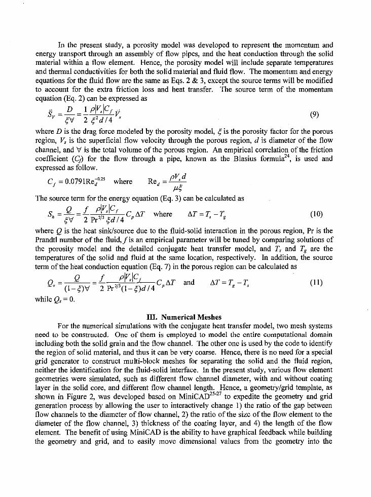
layer in the solid core, and different flow channel length. Hence, a geometry/grid template, asshown in Figure 2, was developed based on MiniCAD 25"27to expedite the geometry and grid
generation process by allowing the user to interactively change 1) the ratio of the gap between
flow channels to the diameter of flow channel, 2) the ratio of the size of the flow element to the
diameter of the flow channel, 3) thickness of the coating layer, and 4) the length of the flow
element. The benefit of using MiniCAD is the ability to have graphical feedback while building
the geometry and grid, and to easily move dimensional values from the geometry into the
template to make it easy to create grids with modified values. In the present study, a 60· pisection of a single flow element, which includes 3 and 1/6 flow channels, was simulated.
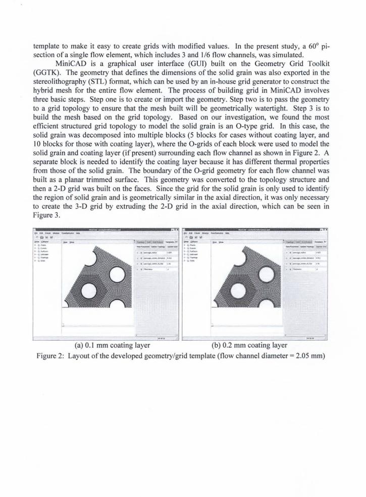
MiniCAD is a graphical user interface (GUl) built on the Geometry Grid Toolkit(GGTK). The geometry that defines the dimensions of the solid grain was also exported in thestereolithography (STL) format, which can be used by an in-house grid generator to construct thehybrid mesh for the entire flow element. The process of building grid in MiniCAD involvesthree basic steps. Step one is to create or import the geometry. Step two is to pass the geometryto a grid topology to ensure that the mesh built will be geometrically watertight. Step 3 is tobuild the mesh based on the grid topology. Based on our investigation, we found the mostefficient structured grid topology to model the solid grain is an O-type grid. In this case, thesolid grain was decomposed into multiple blocks (5 blocks for cases without coating layer, and10 blocks for those with coating layer), where the O-grids of each block were used to model thesolid grain and coating layer (if present) surrounding each flow channel as shown in Figure 2. Aseparate block is needed to identify the coating layer because it has different thermal propertiesfrom those of the solid grain. The boundary of the O-grid geometry for each flow channel wasbuilt as a planar trimmed surface. This geometry was converted to the topology structure andthen a 2-D grid was built on the faces. Since the grid for the solid grain is only used to identifythe region of solid grain and is geometrically similar in the axial direction, it was only necessaryto create the 3-D grid by extruding the 2-D grid in the axial direction, which can be seen inFigure 3.
..------......._---~ -, .-.""6- __'...-
---'- --.. --- ...• , __Jo_ ••
....-..-'...-......---
.. __ .... ,..
(a) 0.1 mm coating layer (b) 0.2 mm coating layer
Figure 2: Layout of the developed geometry/grid template (flow channel diameter =2.05 mm)
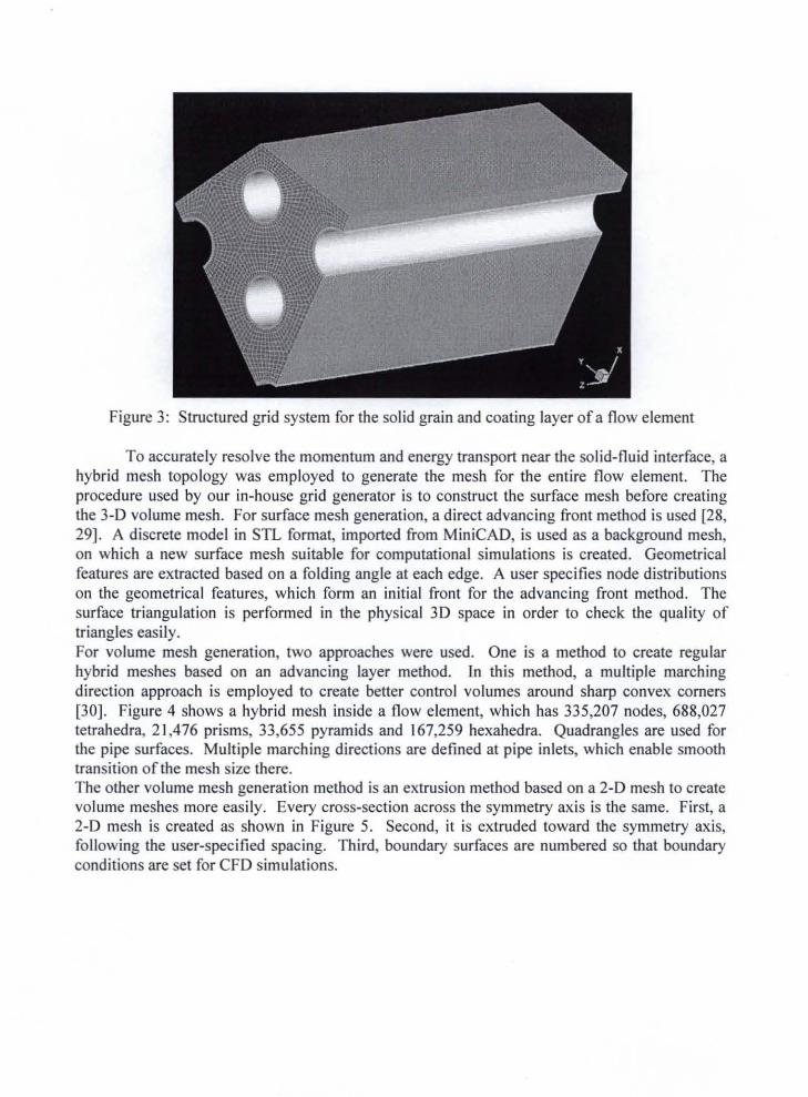
Figure 3: Structured grid system for the solid grain and coating layer of a flow element
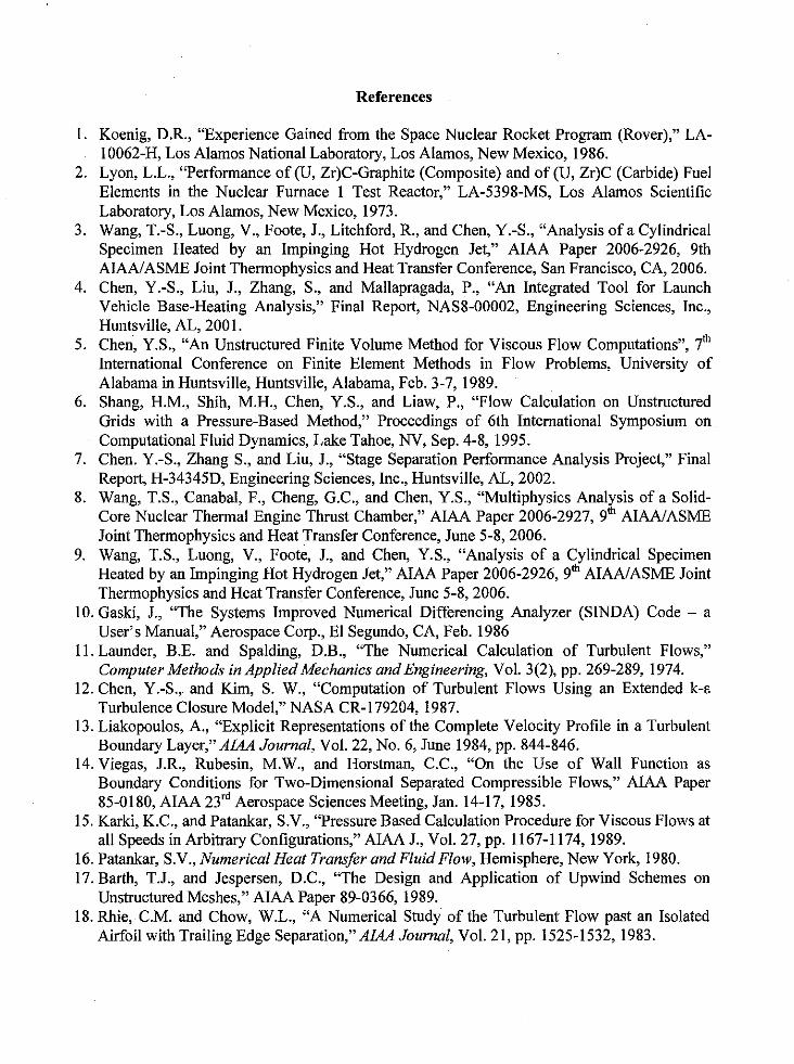
To accurately resolve the momentum and energy transport near the solid-fluid interface, ahybrid mesh topology was employed to generate the mesh for the entire flow element. Theprocedure used by our in-house grid generator is to construct the surface mesh before creatingthe 3-D volume mesh. For surface mesh generation, a direct advancing front method is used [28,29]. A discrete model in STL format, imported from MiniCAD, is used as a background mesh,on which a new surface mesh suitable for computational simulations is created. Geometricalfeatures are extracted based on a folding angle at each edge. A user specifies node distributionson the geometrical features, which form an initial front for the advancing front method. Thesurface triangulation is performed in the physical 3D space in order to check the quality oftriangles easily.For volume mesh generation, two approaches were used. One is a method to create regularhybrid meshes based on an advancing layer method. In this method, a multiple marchingdirection approach is employed to create better control volumes around sharp convex corners[30]. Figure 4 shows a hybrid mesh inside a flow element, which has 335,207 nodes, 688,027tetrahedra, 21,476 prisms, 33,655 pyramids and 167,259 hexahedra. Quadrangles are used forthe pipe surfaces. Multiple marching directions are defined at pipe inlets, which enable smoothtransition of the mesh size there.The other volume mesh generation method is an extrusion method based on a 2-D mesh to createvolume meshes more easily. Every cross-section across the symmetry axis is the same. First, a2-D mesh is created as shown in Figure 5. Second, it is extruded toward the symmetry axis,following the user-specified spacing. Third, boundary surfaces are numbered so that boundaryconditions are set for CFD simulations.
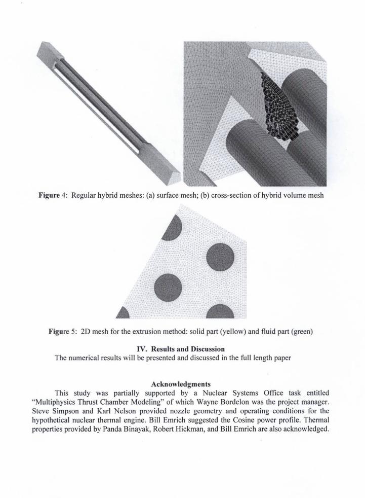
Figure 4: Regular hybrid meshes: (a) surface mesh; (b) cross-section of hybrid volume mesh
Figure 5: 20 mesh for the extrusion method: solid part (yellow) and fluid part (green)
IV. Results and DiscussionThe numerical results will be presented and discussed in the full length paper
AcknowledgmentsThis study was partially supported by a Nuclear Systems Office task entitled
"Multiphysics Thrust Chamber Modeling" of which Wayne Bordelon was the project manager.Steve Simpson and Karl Nelson provided nozzle geometry and operating conditions for thehypothetical nuclear thermal engine. Bill Emrich suggested the Cosine power profile. Thermalproperties provided by Panda Binayak, Robert Hickman, and Bill Emrich are also acknowledged.
References
1. Koenig, D.R., "Experience Gained from the Space Nuclear Rocket Program (Rover)," LA-
10062-H, Los Alamos National Laboratory, Los Alamos, New Mexico, 1986.
2. Lyon, L.L., "Performance of (U, Zr)C-Graphite (Composite) and of (U, Zr)C (Carbide) Fuel
Elements in the Nuclear Furnace 1 Test Reactor," LA-5398-MS, Los Alamos Scientific
Laboratory, Los Alamos, New Mexico, 1973.
3. Wang, T.-S., Luong, V., Foote, J., Litchford, R., and Chen, Y.-S., "Analysis of a Cylindrical
Specimen Heated by an Impinging Hot Hydrogen Jet," AIAA Paper 2006-2926, 9th
AIAA/ASME Joint Thermophysics and Heat Transfer Conference, San Francisco, CA, 2006.
4. Chen, Y.-S., Liu, J., Zhang, S., and Mallapragada, P., "An Integrated Tool for Launch
Vehicle Base-Heating Analysis," Final Report, NAS8-00002, Engineering Sciences, Inc.,Huntsville, AL, 2001.
5. chen, Y.S., "An Unstructured Finite Volume Method for Viscous Flow Computations", 7 th
International Conference on Finite Element Methods in Flow Problems, University of
Alabama in Htmtsville, Huntsville, Alabama, Feb. 3-7, 1989.
6. Shang, H.M., Shih, M.H., Chen, Y.S., and Liaw, P., "Flow Calculation on Unstructured
Grids with a Pressure-Based Method," Proceedings of 6th International Symposium on
Computational Fluid Dynamics, Lake Tahoe, NV, Sep. 4-8, 1995.
7. Chen. Y.-S., Zhang S., and Liu, J., "Stage Separation Performance Analysis Project," Final
Report, H-34345D, Engineering Sciences, Inc., Huntsville, AL, 2002.
8. Wang, T.S., Canabal, F., Cheng, G.C., and Chen, Y.S., "Multiphysics Ana!_sis of a Solid-Core Nuclear Thermal Engine Thrust Chamber," AIAA Paper 2006-2927, 9 AIAA/ASME
Joint Thermophysics and Heat Transfer Conference, June 5-8, 2006.
9. Wang, T.S., Luong, V., Foote, J., and Cher_ Y.S., "Analysis of a Cylindrical Specimen,, th
Heated by an Impinging Hot Hydrogen Jet, AIAA Paper 2006-2926, 9 AIAA/ASME Joint
Thermophysics and Heat Transfer Conference, June 5-8, 2006.
10. Gaski, J., "The Systems Improved Numerical Differencing Analyzer (S1NDA) Code - a
User's Manual," Aerospace Corp., El Segundo, CA, Feb. 1986
11. Launder, B.E. and Spalding, D.B., "The Numerical Calculation of Turbulent Flows,"
Computer Methods in Applied Mechanics and Engineering, Vol. 3(2), pp. 269-289, 1974.
12. Chen, Y.-S., and Kim, S. W., "Computation of Turbulent Flows Using an Extended k-_Turbulence Closure Model," NASA CR-179204, 1987.
13. Liakopoulos, A., "Explicit Representations of the Complete Velocity Profile in a Turbulent
Boundary Layer," AIAA Journal, Vol. 22, No. 6, June 1984, pp. 844-846.
14. Viegas, J.R., Rubesin, M.W., and Horstman, C.C., "On the Use of Wall Function as
Boundary Conditions for Two-Dimensional Separated Compressible Flows," AIAA Paper
85-0180, AIAA 23 ra Aerospace Sciences Meeting, Jan. 14-17, 1985.
15. Karki, K.C., and Patankar, S.V., "Pressure Based Calculation Procedure for Viscous Flows at
all Speeds in Arbitrary Configurations," AIAA J., Vol. 27, pp. 1167-1174, 1989.
16. Patankar, S.V., Numerical Heat Transfer and Fluid Flow, Hemisphere, New York, 1980.
17. Barth, T.J., and Jespersen, D.C., "The Design and Application of Upwind Schemes on
Unstructured Meshes," AIAA Paper 89-0366, 1989.
18. Rhie, C.M. and Chow, W.L., "A Numerical Study of the Turbulent Flow past an Isolated
Airfoil with Trailing Edge Separation," AIAA Journal, Vol. 21, pp. 1525-1532, 1983.
19.VanDerVorst,H.A., "Bi-CGSTAB:A FastandSmoothlyConvergingVariantof Bi-CGfortheSolutionof NonsymmetricLinearSystems,"SIAMZ Sci. Stat. Comput., Vol. 13(2), pp.
631-644, 1992.
20. Saad,Y. and Schultz, M.H., "GMRES: A Generalized Minimal Residual Algorithm for
Solving Nonsymmetric Linear Systems," SIAMZ Sci. Stat. Comput., Vol. 7(3), pp. 856-869,1986.
21. Raw, M., "Robustness of Coupled Algebric Multigrid for the Navier-Stkoes Equations,"
AIAA Paper 96-0297, 1996.
22. W. Gropp, E. Lusk, and A. Skjellum, "Using MPI", published by MIT Press, ISBN 0-262-57104-8.
23. Karypis and V. Kumar, "METIS, A Software Package for Partitioning Unstructured Graphs,
Partitioning Meshes, and Computing Fill-Reducing Orderings of Sparse Matrices," Version
3.0.3, November 5, 1997.
24. Bird, R.B., Stewart, W.E., and Lightfoot, E.N., "Transport Phenomena," 2nd Ed., John Wiley
& Sons, Inc.
25. Ross, D.H., Dillavou, M., Gopalsamy, S., Shum, P.C., and Shih, A.M., "A Framework for
Developing Geometry-Grid Templates for Propulsion Elements," the 16th NASA Thermal
and Fluids Analysis Workshop, Orlando, FL, August 8-12, 2005.
26. Shih, A. M., Gopalsamy, S., Ito, Y., Ross, D. H., Dillavou, M. and Soni, B. K., "Automatic
and Parametric Mesh Generation Approach," 17th International Association for Mathematics
and Computers in Simulation (IMACS) World Congress, Paris, France, July 2005.
27. Shih, A.M., Ross, D.H., Dillavou, M., Gopalsamy, S., Soni, B.K., Peugeot, J.W., and Griffin,
L.W., "A Geometry-Grid Generation Template Framework for Propellant Delivery System,"
42nd AIAMASME/SAE/ASEE Joint Propulsion Conference and Exhibit, Sacramento, CA,
July, 2006.
Ito, Y. and Nakahashi, K., "Direct Surface Triangulation Using Stereolithograpby Data,"
AIAA Journal, Vol. 40, No. 3, March 2002, pp. 490-496.
Ito, Y. and Nakahashi, K., "Surface Triangulation for Polygonal Models Based on CAD
Data," International Journal for Numerical Methods in Fluids, Vol. 39, Issue 1, May 2002,
pp. 75-96.
30. Ito, Y., Shih, A. M., Soni, B. K. and Nakahashi, K., "An Approach to Generate High QualityUnstructured Hybrid Meshes," AIAA Paper 2006-0530, 44 th AIAA Aerospace Sciences
Meeting and Exhibit, Reno, NV, January 2006.
28.
29.