Embed Size (px)
Citation preview
applied sciences
Article
Development of an Array of Compound RefractiveLenses for Sub-Pixel Resolution, Large Field of View,and Time-Saving in Scanning Hard X-ray Microscopy
Talgat Mamyrbayev 1,*, Alexander Opolka 1,*, Alexey Ershov 2, Josephine Gutekunst 1,Pascal Meyer 1, Katsumasa Ikematsu 1,3 , Atsushi Momose 3 and Arndt Last 1
1 Institute of Microstructure Technology (IMT), Karlsruhe Institute of Technology (KIT),Hermann-von-Helmholtz-Platz 1, 76344 Eggenstein-Leopoldshafen, Germany;[email protected] (J.G.); [email protected] (P.M.); [email protected] (K.I.);[email protected] (A.L.)
2 Institute for Photon Science and Synchrotron Radiation (IPS), Karlsruhe Institute of Technology (KIT),Hermann-von-Helmholtz-Platz 1, 76344 Eggenstein-Leopoldshafen, Germany; [email protected]
3 Institute of Multidisciplinary Research for Advanced Materials, Tohoku University, 2-1-1 Katahira, Aoba-ku,Sendai 980-8577, Japan; [email protected]
* Correspondence: [email protected] (T.M.); [email protected] (A.O.)
Received: 7 May 2020; Accepted: 11 June 2020; Published: 16 June 2020�����������������
Abstract: A two-dimensional array of compound refractive lenses (2D array of CRLs) designed forhard X-ray imaging with a 3.5 mm2 large field of view is presented. The array of CRLs consistsof 2D polymer biconcave parabolic 34 × 34 multi-lenses fabricated via deep X-ray lithography.The developed refractive multi-lens array was applied for sub-pixel resolution scanning transmissionX–ray microscopy; a raster scan with only 55 × 55 steps provides a 3.5 megapixel image. The opticalelement was experimentally characterized at the Diamond Light Source at 34 keV. An array of pointfoci with a 55 µm period and an average size of ca. 2.1 µm × 3.6 µm was achieved. In comparison withthe conventional scanning transmission microscopy using one CRL, sub-pixel resolution scanningtransmission hard X-ray microscopy enables a large field of view and short scanning time whilekeeping the high spatial resolution.
Keywords: two-dimensional compound refractive lens array; deep X-ray lithography;scanning transmission X-ray microscopy; sub-pixel resolution
1. Introduction
Over the past few decades, an array of compound refractive lenses (CRLs [1–3]) for hard X-rays, alsoknown as a Shack–Hartmann sensor (SHS), has been applied for wavefront analysis and multi-contrastimaging of weakly absorbing and porous objects with significantly reduced single exposure time dueto the focusing properties of CRLs [4,5]. When a monochromatic X-ray plane wave illuminates a CRLarray, an array of point foci is generated. A weakly absorbing object placed in front of or just behindthe SHS leads to a displacement of the foci in the detector plane, allowing for reconstructing of aphase-contrast image. In the case of a porous object, the foci broaden, indicating scattering effectsand resulting in a dark-field contrast image. Each contrast (absorption, phase, and scattering) canbe reconstructed via Fourier transform or two-dimensional (2D) Gaussian fitting [6,7]. That methodprovides high temporal resolution and high sensitivity.
Using an array of CRLs, the local X-ray flux density is increased at the focal distance. Accordingly,the so-called single-shot X-ray multi-contrast imaging based on an array of CRLs, in combination withhigh frame-rate detectors, provides microsecond temporal resolution and allows for the investigation
Appl. Sci. 2020, 10, 4132; doi:10.3390/app10124132 www.mdpi.com/journal/applsci
Appl. Sci. 2020, 10, 4132 2 of 9
of dynamic processes [8]. However, the spatial resolution of this technique is equal to the distancebetween neighboring point foci and, consequently, to the period of the 2D array (tens of microns) [6].The spatial resolution could be enhanced by scanning the object through a large number of pointfoci in combination with the super-resolution reconstruction, as was demonstrated using the 1D-linearray of line focus CRLs [9]. Nevertheless, by utilizing the 1D array of CRLs, the spatial resolutionis increased only in the scanning direction and limited by the X-ray line focus size (full width halfmaximum, FWHM). Thus, in the direction perpendicular to the scan direction it is equal to the sizeof a low resolution detector pixel. Consequently, the development of a 2D array of CRLs generatingthe point foci in the (sub-) µm range will overcome the mentioned limitations and increase the spatialresolution in both directions.
Recently, the use of 2D refractive lens arrays, fabricated either by additive manufacturing of apolymer with low radiation stability or by an embossing process of polyimide foils using a needle withparaboloid tip, were demonstrated for energies below 15 keV and for a field of view (FoV) of 1 mm2 and6.5 × 6.5 mm2, which limits the scope of the samples studied [10,11]. Fabrication of 2D CRLs for higherenergies by these techniques is a challenging task at the moment. Moreover, the current 2D refractivelenses include stitching/shifting errors, influencing the focusing performance (the point foci size is inthe range of ten microns). The use of higher photon energies would allow for the study of opticallythick objects, which are of high interest for the material sciences, for example, for characterization ofcracks distribution in metallic plates and composite materials. Therefore, the target of this work wasthe development of X-ray CRL arrays for higher energies (from 15 keV to 100 keV), generating smallerpoint foci, allowing for a spatial resolution in the (sub-) µm range with a large area (>1 mm2) to studyrelatively big samples.
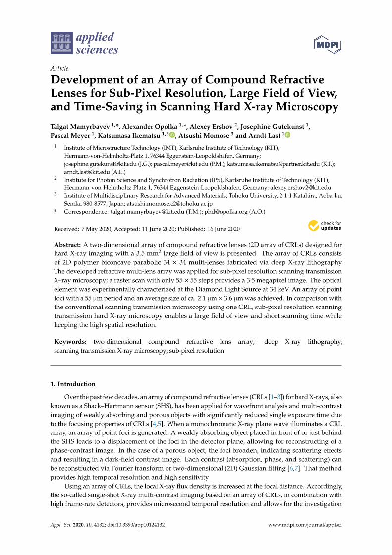
We present a 2D 34 × 34 multi-lens array for sub-pixel resolution scanning transmission hardX–ray imaging (see Figure 1). This array has biconcave parabolic refracting surfaces, offers 1156 foci ina 3.5 mm2 large field of view, and is made out of a radiation stable polymer. The required detector onlyneeds large 55 µm × 55 µm pixels. Scanning the sample with steps clearly below the detector’s pixelsize and slightly below the focal spot size of the individual lenslets provides a resolution in the rangeof the focal spot size over the entire field of view. This multi-lens array can be beneficially used forhard X-ray microscopy applications.
Figure 1. Principle of 2D X-ray multi-contrast imaging with the sample positioned in front of the detectorfor absorption contrast imaging. Illuminated by the X-ray beam, the 2D multi-lens array generates an arrayof point foci. The sample is placed in the focal plane. At each sample position, the intensity variationsare recorded by a low resolution (LR) detector, which is placed as near as possible behind the sample.The physical aperture of the individual lenslets of the array matches the pixel size. Each focal point hitsits corresponding pixel in the center. Sub-pixel resolution scanning transmission X-ray microscopy isachieved by raster-scanning the sample with sub-pixel sized steps through the point foci.
Appl. Sci. 2020, 10, 4132 3 of 9
2. Materials and Methods
Two-Dimensional Multi-Lens Array Design and Fabrication
The design of a 2D array of CRLs, suitable for sub-pixel resolution scanning transmission hardX-ray microscopy, is presented.
A Medipix Merlin 3.0 photon-counting detector (FoV 14 mm × 14 mm, 256 × 256 pixels, 55 µmpixel size, CERN, Geneva, Switzerland) working in charge summing mode was used to fix the physicalaperture of the individual CRLs [12]. In a 2D array of CRLs, the period of the focal points grid has to beequal to the pixel pitch of the detector; so, the individual CRLs physical apertures are 55 µm × 55 µm.
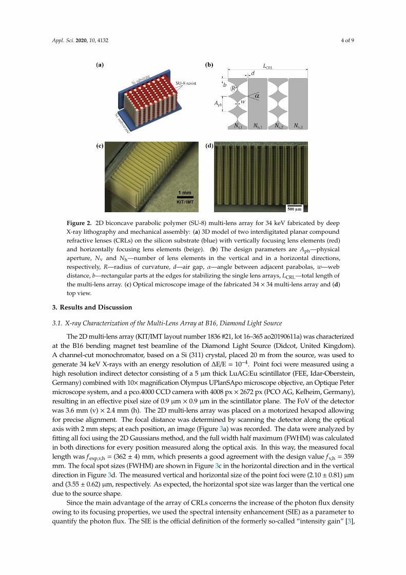
Deep X-ray lithography was used to fabricate such an array of CRLs [13]. This technique providesstructures with parallel, smooth sidewalls with a roughness of about 20 nm [14]. It allows for producingthe required parabolic shape of the refracting surfaces, sub-micrometer radii of curvature, and structureheights of up to 2.5 mm at KIT/IMT. We made an SHS of 34 × 34 single CRLs, resulting in a totalentrance aperture of 1.87 mm × 1.87 mm, produced in a 2 mm high resist of type SU-8. SU-8 is anepoxy-based negative resist, which is radiation stable up to a deposited dose of at least 2 MJ/cm3 [15].The SU-8 resist (micro resist technology GmbH, Berlin) comes on a 525 µm silicon substrate. The X-rayabsorber working mask was made of 20 µm gold absorbers on a 2.5 µm titanium membrane and wasused to create SU-8 1D CRLs via deep X-ray lithography. The exposure dose was 19,845 mA*min/cm3.After irradiation, it was post-exposure baked on the hot plate at 66 ◦C for 20 h. Then, unexposed resistwas removed from the substrate during the development process. The developer solution was asfollows: propylene glycol methyl ether acetate (PGMEA) for 2 h then rinsed in isopropanol for 30 min.After that, it was air-dried. Lithographic processes only provided 1D line focus lenses. Consequently,the substrate was cut by a diamond wafer saw, and to realize a point focus SHS, one of the line focuslenses had to be rotated 90◦ around the optical axis and mounted in an interdigitated way [16,17].
We characterized the array of CRLs at the Diamond Light Source beamline B16 to demonstrateits functionality at high photon energies. The array of CRLs was designed for 34 keV. At thisenergy, the photon flux is about 1 × 10⁹ ph/sec/mm2. The vertical and horizontal focal lengths, f v,h,of the multi-lens array were chosen as f v,h = 359 mm, a good compromise between small focusdue to source demagnification, angular resolution, diffraction limit, and short focal length [18].The number of lens elements per focusing direction is N = 92, the radius of curvature Rv,h = 15.9 µm,and the physical aperture Aph = 55 µm, resulting in an angle between adjacent parabolas of α = 60◦
(Figure 2). The parameters for vertically (v) and horizontally (h) focusing lens elements are identical.The size of the elliptical source of the Diamond Light Source is approximately sx,y = 56 µm × 126 µm(vertical × horizontal, FWHM), the image distance is L2 = 362 mm and the source distance is L1 =
46.059 m.Each lens element has two rectangular stabilization parts with b = 40 µm at the edges of each
single lens array, resulting in a total lens element width of 34 × 55 µm + 2 × 40 µm = 1950 µm. To obtainmechanically stable lens elements, the web distance, w, was chosen to be relatively large; w = 25 µm.With 50 µm air gaps, d, between neighbor lens elements along the optical axis, this results in a multi-lensarray with a total length of LCRL = 22.5 mm calculated by:
LCRL = 2Nv,h1
Rv,h
(Aph (v,h)
2
)2
+ 2Nv,hw + (2Nv,h − 1)d, (1)
The designed focal length, f v,h, of this multi-lens array is approximately [18]
fv,h ≈Rv,h
2δNv,h+
LCRL
6≈ 359 mm, (2)
using a refractive index decrement of δ ≈ 0.000281(E/keV)2 ≈ 2.43× 10⁻⁷ [19,20].
Appl. Sci. 2020, 10, 4132 4 of 9
Figure 2. 2D biconcave parabolic polymer (SU-8) multi-lens array for 34 keV fabricated by deepX-ray lithography and mechanical assembly: (a) 3D model of two interdigitated planar compoundrefractive lenses (CRLs) on the silicon substrate (blue) with vertically focusing lens elements (red)and horizontally focusing lens elements (beige). (b) The design parameters are Aph—physicalaperture, Nv and Nh—number of lens elements in the vertical and in a horizontal directions,respectively, R—radius of curvature, d—air gap, α—angle between adjacent parabolas, w—webdistance, b—rectangular parts at the edges for stabilizing the single lens arrays, LCRL—total length ofthe multi-lens array. (c) Optical microscope image of the fabricated 34 × 34 multi-lens array and (d)top view.
3. Results and Discussion
3.1. X-ray Characterization of the Multi-Lens Array at B16, Diamond Light Source
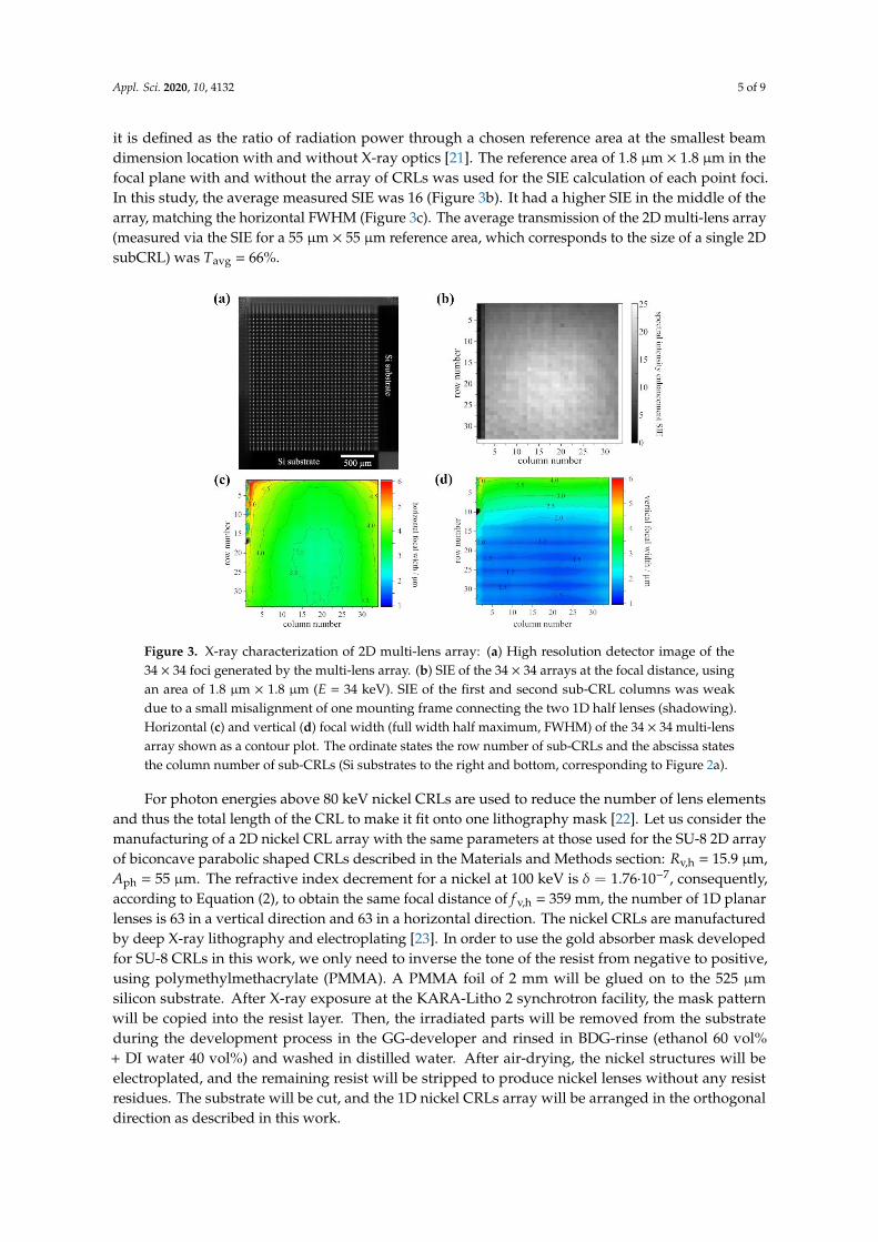
The 2D multi-lens array (KIT/IMT layout number 1836 #21, lot 16–365 ao20190611a) was characterizedat the B16 bending magnet test beamline of the Diamond Light Source (Didcot, United Kingdom).A channel-cut monochromator, based on a Si (311) crystal, placed 20 m from the source, was used togenerate 34 keV X-rays with an energy resolution of ∆E/E = 10−4. Point foci were measured using ahigh resolution indirect detector consisting of a 5 µm thick LuAG:Eu scintillator (FEE, Idar-Oberstein,Germany) combined with 10×magnification Olympus UPlanSApo microscope objective, an Optique Petermicroscope system, and a pco.4000 CCD camera with 4008 px × 2672 px (PCO AG, Kelheim, Germany),resulting in an effective pixel size of 0.9 µm × 0.9 µm in the scintillator plane. The FoV of the detectorwas 3.6 mm (v) × 2.4 mm (h). The 2D multi-lens array was placed on a motorized hexapod allowingfor precise alignment. The focal distance was determined by scanning the detector along the opticalaxis with 2 mm steps; at each position, an image (Figure 3a) was recorded. The data were analyzed byfitting all foci using the 2D Gaussians method, and the full width half maximum (FWHM) was calculatedin both directions for every position measured along the optical axis. In this way, the measured focallength was f exp,v,h = (362 ± 4) mm, which presents a good agreement with the design value f v,h = 359mm. The focal spot sizes (FWHM) are shown in Figure 3c in the horizontal direction and in the verticaldirection in Figure 3d. The measured vertical and horizontal size of the point foci were (2.10 ± 0.81) µmand (3.55 ± 0.62) µm, respectively. As expected, the horizontal spot size was larger than the vertical onedue to the source shape.
Since the main advantage of the array of CRLs concerns the increase of the photon flux densityowing to its focusing properties, we used the spectral intensity enhancement (SIE) as a parameter toquantify the photon flux. The SIE is the official definition of the formerly so-called “intensity gain” [3],
Appl. Sci. 2020, 10, 4132 5 of 9
it is defined as the ratio of radiation power through a chosen reference area at the smallest beamdimension location with and without X-ray optics [21]. The reference area of 1.8 µm × 1.8 µm in thefocal plane with and without the array of CRLs was used for the SIE calculation of each point foci.In this study, the average measured SIE was 16 (Figure 3b). It had a higher SIE in the middle of thearray, matching the horizontal FWHM (Figure 3c). The average transmission of the 2D multi-lens array(measured via the SIE for a 55 µm × 55 µm reference area, which corresponds to the size of a single 2DsubCRL) was Tavg = 66%.
Figure 3. X-ray characterization of 2D multi-lens array: (a) High resolution detector image of the34 × 34 foci generated by the multi-lens array. (b) SIE of the 34 × 34 arrays at the focal distance, usingan area of 1.8 µm × 1.8 µm (E = 34 keV). SIE of the first and second sub-CRL columns was weakdue to a small misalignment of one mounting frame connecting the two 1D half lenses (shadowing).Horizontal (c) and vertical (d) focal width (full width half maximum, FWHM) of the 34 × 34 multi-lensarray shown as a contour plot. The ordinate states the row number of sub-CRLs and the abscissa statesthe column number of sub-CRLs (Si substrates to the right and bottom, corresponding to Figure 2a).
For photon energies above 80 keV nickel CRLs are used to reduce the number of lens elementsand thus the total length of the CRL to make it fit onto one lithography mask [22]. Let us consider themanufacturing of a 2D nickel CRL array with the same parameters at those used for the SU-8 2D arrayof biconcave parabolic shaped CRLs described in the Materials and Methods section: Rv,h = 15.9 µm,Aph = 55 µm. The refractive index decrement for a nickel at 100 keV is δ = 1.76·10−7, consequently,according to Equation (2), to obtain the same focal distance of f v,h = 359 mm, the number of 1D planarlenses is 63 in a vertical direction and 63 in a horizontal direction. The nickel CRLs are manufacturedby deep X-ray lithography and electroplating [23]. In order to use the gold absorber mask developedfor SU-8 CRLs in this work, we only need to inverse the tone of the resist from negative to positive,using polymethylmethacrylate (PMMA). A PMMA foil of 2 mm will be glued on to the 525 µmsilicon substrate. After X-ray exposure at the KARA-Litho 2 synchrotron facility, the mask patternwill be copied into the resist layer. Then, the irradiated parts will be removed from the substrateduring the development process in the GG-developer and rinsed in BDG-rinse (ethanol 60 vol%+ DI water 40 vol%) and washed in distilled water. After air-drying, the nickel structures will beelectroplated, and the remaining resist will be stripped to produce nickel lenses without any resistresidues. The substrate will be cut, and the 1D nickel CRLs array will be arranged in the orthogonaldirection as described in this work.
Appl. Sci. 2020, 10, 4132 6 of 9
3.2. Application of the 2D Multi-Lens Array for 2D Sub-Pixel Resolution Scanning TransmissionX-ray Imaging
The low spatial resolution of the standard non-scanning technique using an array of CRLs isdetermined by the distance between neighboring point foci. Scanning the sample with sub-pixel sizesteps overcomes this limitation. In visible light microscopy, generating a high resolution image from aset of low resolution images, which are sub-pixel shifted, is known as the pixel super-resolution (SR)technique [24]. To avoid confusion, we here use the term sub-pixel resolution instead of super-resolution,where the resolution is below the diffraction limit [25].
Two dimensional sub-pixel resolution scanning transmission X-ray imaging is a straightforwardextension of the one-dimensional method described in [9] and is shown in Figure 1. The point fociwith an intensity I0(x, y) created by the 2D multi-lens array, are recorded by a Medipix Merlin 3.0photon-counting detector. The region of interest of the Medipix detector was chosen to be 34 × 34 pixelscorresponding to the geometrical size of the 2D multi-lens array. The 2D multi-lens array is positionedin the beam and aligned parallel to the detector by rotating it around the optical axis. It is parallelwhen a detector pixels row switches from completely dark to fully illuminated when shifting the fociof the 2D multi-lens array over the border between pixels in the vertical direction. In the same way,a column of foci is positioned above the border between detector pixels by moving the foci of the 2Dmulti-lens array over the detector pixels in a horizontal direction. From that position of the array ofCRLs, the foci are easily centered on the detector pixels by shifting them by half a pixel pitch in verticaland in the horizontal direction. The size of the point foci is much smaller than the pixel size p = 55 µm.Each focus must illuminate only one pixel.
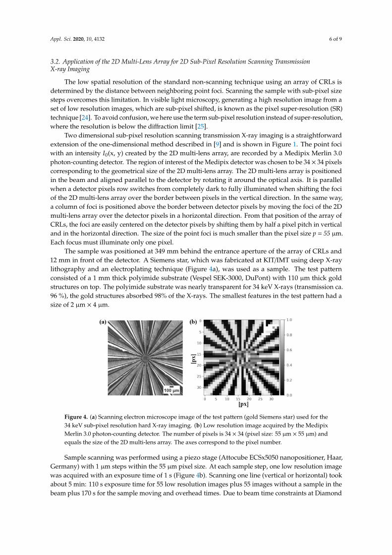
The sample was positioned at 349 mm behind the entrance aperture of the array of CRLs and12 mm in front of the detector. A Siemens star, which was fabricated at KIT/IMT using deep X-raylithography and an electroplating technique (Figure 4a), was used as a sample. The test patternconsisted of a 1 mm thick polyimide substrate (Vespel SEK-3000, DuPont) with 110 µm thick goldstructures on top. The polyimide substrate was nearly transparent for 34 keV X-rays (transmission ca.96 %), the gold structures absorbed 98% of the X-rays. The smallest features in the test pattern had asize of 2 µm × 4 µm.
Figure 4. (a) Scanning electron microscope image of the test pattern (gold Siemens star) used for the34 keV sub-pixel resolution hard X-ray imaging. (b) Low resolution image acquired by the MedipixMerlin 3.0 photon-counting detector. The number of pixels is 34 × 34 (pixel size: 55 µm × 55 µm) andequals the size of the 2D multi-lens array. The axes correspond to the pixel number.
Sample scanning was performed using a piezo stage (Attocube ECSx5050 nanopositioner, Haar,Germany) with 1 µm steps within the 55 µm pixel size. At each sample step, one low resolution imagewas acquired with an exposure time of 1 s (Figure 4b). Scanning one line (vertical or horizontal) tookabout 5 min: 110 s exposure time for 55 low resolution images plus 55 images without a sample in thebeam plus 170 s for the sample moving and overhead times. Due to beam time constraints at Diamond
Appl. Sci. 2020, 10, 4132 7 of 9
B16, we could only complete two line scans, one in the vertical and one in the horizontal directioninstead of a full raster scan. All X-ray images were flat field and dark field corrected.
Sub-pixel resolution image reconstruction was performed according to:
ASR(Mx + m, Ly + l) =I(x, y)I0(x, y)
[S(
m× pM
,l× p
L
)], (3)
Incident X-ray point focus intensity generated by the 2D multi-lens, I0(x, y); intensity variationdue to the absorption by the sample, I(x, y); m, l represent the step number, therefore, m = 1, . . . , M
and l = 1, . . . , L; and S(
m×pM , l×p
L
)is the raster scanning of the sample in two directions [26].
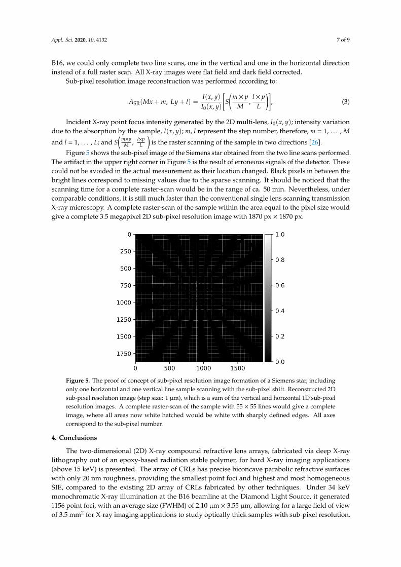
Figure 5 shows the sub-pixel image of the Siemens star obtained from the two line scans performed.The artifact in the upper right corner in Figure 5 is the result of erroneous signals of the detector. Thesecould not be avoided in the actual measurement as their location changed. Black pixels in between thebright lines correspond to missing values due to the sparse scanning. It should be noticed that thescanning time for a complete raster-scan would be in the range of ca. 50 min. Nevertheless, undercomparable conditions, it is still much faster than the conventional single lens scanning transmissionX-ray microscopy. A complete raster-scan of the sample within the area equal to the pixel size wouldgive a complete 3.5 megapixel 2D sub-pixel resolution image with 1870 px × 1870 px.
Figure 5. The proof of concept of sub-pixel resolution image formation of a Siemens star, includingonly one horizontal and one vertical line sample scanning with the sub-pixel shift. Reconstructed 2Dsub-pixel resolution image (step size: 1 µm), which is a sum of the vertical and horizontal 1D sub-pixelresolution images. A complete raster-scan of the sample with 55 × 55 lines would give a completeimage, where all areas now white hatched would be white with sharply defined edges. All axescorrespond to the sub-pixel number.
4. Conclusions
The two-dimensional (2D) X-ray compound refractive lens arrays, fabricated via deep X-raylithography out of an epoxy-based radiation stable polymer, for hard X-ray imaging applications(above 15 keV) is presented. The array of CRLs has precise biconcave parabolic refractive surfaceswith only 20 nm roughness, providing the smallest point foci and highest and most homogeneousSIE, compared to the existing 2D array of CRLs fabricated by other techniques. Under 34 keVmonochromatic X-ray illumination at the B16 beamline at the Diamond Light Source, it generated1156 point foci, with an average size (FWHM) of 2.10 µm × 3.55 µm, allowing for a large field of viewof 3.5 mm2 for X-ray imaging applications to study optically thick samples with sub-pixel resolution.
Appl. Sci. 2020, 10, 4132 8 of 9
Moreover, the demand for the X-ray focusing optics for high photon energies is very high due toan exponential decrease of the spectral photon flux with increasing photon energy at bending magnetsynchrotron radiation sources. The realization of a 2D array of CRLs made of nickel for the photonenergies above 80 keV is feasible using the same technique and was discussed in this study. Therefore,the 2D multi-lens array is an attractive optical element for hard X-ray microscopy applications requiringlarge FoV and high spatial resolution at synchrotron facilities.
Author Contributions: T.M., K.I., and A.M. worked out the conceptual idea of super-resolution scanningtransmission X-ray microscopy. A.O., T.M. designed and A.O. and A.L. fabricated the 2D multi-lens array. P.M.fabricated the test pattern. A.O., A.L., and J.G. performed the experiment. T.M., K.I., and A.E. developed thereconstruction algorithm and analyzed the microscopy data. A.O., J.G., and A.L. evaluated the data for themulti-lens array characterization. The manuscript was written by T.M. with support from all of the co-authors.All authors have read and agreed to the published version of the manuscript.
Funding: This research was funded by Exploratory Research for Advanced Technology (ERATO), grantnumber JPMJER1403.
Acknowledgments: We thank Diamond B16 for the beam time provided and Fox, O. and Sawhney, K. For theirkind support at the beamline. The research leading to this result has been supported by the project CALIPSOplusunder Grant Agreement 730872 from the EU Framework Program for Research and Innovation HORIZON 2020.The authors acknowledge the support of the Karlsruhe Nano Micro Facility (KNMF), a Helmholtz ResearchInfrastructure at Karlsruhe Institute of Technology, and the Karlsruhe School of Optics and Photonics (KSOP).We acknowledge support by the KIT-Publication Fund of the Karlsruhe Institute of Technology.
Conflicts of Interest: The authors declare no conflict of interest.
References
1. Snigirev, A.; Kohn, V.; Snigireva, I.; Lengeler, B. A compound refractive lens for focusing high-energy X-rays.Nature 1996, 384, 49–51. [CrossRef]
2. Lengeler, B.; Schroer, C.G.; Benner, B.; Gerhardus, A.; Gunzler, T.F.; Kuhlmann, M.; Meyer, J.; Zimprich, C.Parabolic refractive X-ray lenses. J. Synchrotron Rad. 2002, 9, 119–124. [CrossRef] [PubMed]
3. Lengeler, B.; Tümmler, J. Transmission and gain of singly and doubly focusing refractive X-ray lenses.J. Appl. Phys. 1998, 84, 5855–5861. [CrossRef]
4. Mayo, S.C.; Sexton, B. Refractive microlens array for wave-front analysis in the medium to hard X-ray range.Opt. Lett. 2004, 29, 866–868. [CrossRef]
5. Wen, H.; Bennett, E.; Hegedus, M.M.; Carroll, S.C. Spatial harmonic imaging of X-ray scattering—Initialresults. IEEE Trans. Med. Imaging 2008, 27, 997–1002. [CrossRef]
6. Dos Santos Rolo, T.; Reich, S.; Karpov, D.; Gasilov, S.; Kunka, D.; Fohtung, E.; Baumbach, T.; Plech, A.A Shack-Hartmann sensor for single-shot multi-contrast imaging with hard X-rays. Appl. Sci. 2018, 8, 737.[CrossRef]
7. Reich, S.; dos Santos Rolo, T.; Letzel, A.; Baumbach, T.; Plech, A. Scalable, large area compound arrayrefractive lens for hard X-rays. Appl. Phys. Lett. 2018, 112, 151903. [CrossRef]
8. Letzel, A.; Reich, S.; dos Santos Rolo, T.; Kanitz, A.; Hoppius, J.; Rack, A.; Olbinado, M.; Ostendorf, A.;Gökce, B.; Plech, A.; et al. Time and Mechanism of Nanoparticle Functionalization by MacromolecularLigands during Pulsed Laser Ablation in Liquids. Langmuir 2019, 25, 3038–3047. [CrossRef]
9. Mamyrbayev, T.; Ikematsu, K.; Meyer, P.; Ershov, A.; Momose, A.; Mohr, J. Super-resolution scanningtransmission X-ray imaging using single biconcave parabolic refractive lens array. Sci. Rep. 2019, 9, 14366.[CrossRef]
10. Mirzaeimoghri, M.; Morales Martinez, A.; Panna, A.; Bennett, E.E.; Lucotte, B.M.; DeVoe, D.L.; Wen, H.Nano-printed miniature compound refractive lens for desktop hard X-ray microscopy. PLoS ONE 2018, 13.[CrossRef]
11. Mikhaylov, A.; Reich, S.; Zakharova, M.; Vlnieska, V.; Laptev, R.; Plech, A.; Kunka, D. Shack–Hartmannwavefront sensors based on 2D refractive lens arrays and super-resolution multi-contrast X-ray imaging.J. Synchrotron Rad. 2020, 27, 788–795. [CrossRef]
12. Ballabriga, R.; Alozy, J.; Blaj, G.; Campbell, M.; Fiederle, M.; Frojdh, E.; Heijne, E.; Llopart, X.; Pichotka, M.;Procz, S.; et al. The MEDIPIX3RX: A high resolution, zero dead-time pixel detector readout chip allowingspectroscopic imaging. J. Instrum. 2013, 8, C02016. [CrossRef]
Appl. Sci. 2020, 10, 4132 9 of 9
13. Meyer, P.; Schulz, J. Micromanufacturing Engineering and Technology, 2nd ed.; Elsevier Inc.: Boston, MA, USA,2015; Chapter 16.
14. Last, A.; Mohr, J. Fehllicht in LIGA-Mikrospektrometern, Forschungszentrum Karlsruhe GmbH. Ph.D.Dissertation, Wissenschaftliche Berichte.FZKA-6585, Univ. Karlsruhe, Karlsruhe, Germany, 2003. [CrossRef]
15. Nazmov, V.; Reznikova, E.; Mohr, J.; Snigirev, A.; Snigireva, I.; Achenbach, S.; Saile, V. Fabrication andpreliminary testing of X-ray lenses in thick SU-8 resist layers. Microsyst. Technol. 2004, 10, 716–721. [CrossRef]
16. Nazmov, V.; Reznikova, E.; Mohr, J.; Saile, V.; Vincze, L.; Vekemans, B.; Bohic, S.; Somogyi, A. Paraboliccrossed planar polymeric X-ray lenses. J. Micromech. Microeng. 2011, 21, 015020. [CrossRef]
17. Kornemann, E.; Márkus, O.; Opolka, A.; Zhou, T.; Greving, I.; Storm, M.; Krywka, C.; Last, A.; Mohr, J.Miniaturized compound refractive X-ray zoom lens. Opt. Express 2017, 25, 22455–22466. [CrossRef] [PubMed]
18. Kohn, V.; Snigireva, I.; Snigirev, A. Diffraction theory of imaging with X-ray compound refractive lens.Opt. Commun. 2003, 216, 247–260. [CrossRef]
19. Kornemann, E.; Zhou, T.; Márkus, O.; Opolka, A.; Schuelli, T.U.; Mohr, J.; Last, A. X-ray zoom lens allows forenergy scans in X-ray microscopy. Opt. Express 2019, 27, 185–195. [CrossRef]
20. Jark, W.; Opolka, A.; Cecilia, A.; Last, A. Zooming X-rays with a single rotation in X-ray prism zoom lenses(XPZL). Opt. Express 2019, 27, 16781–16790. [CrossRef]
21. VDI/VDE 5575 Part 1: 2007-12 X-Ray Optical Systems; Terms and Definition; Beuth Verlag: Berlin, Germany, 2017.22. Snigirev, A.A.; Snigireva, I.I.; Di Michiel, M.; Honkimaki, V.; Grigoriev, M.V.; Nazmov, V.P.; Reznikova, E.F.;
Mohr, J.; Saile, V. Sub-micron focusing of high energy X-rays with Ni refractive lenses. Proc. SPIE 2004, 5539,244–250.
23. Nazmov, V.; Reznikova, E.; Snigirev, A.; Snigireva, I.; Di Michiel, M.; Grigoriev, M.; Mohr, J.; Matthis, B.;Saile, V. LIGA fabrication of X-ray Nickel lenses. Microsyst. Technol. 2005, 11, 292–297. [CrossRef]
24. Luo, W.; Zhang, Y.; Feizi, A.; Göröcs, Z.; Ozcan, A. Pixel super-resolution using wavelength scanning.Light Sci. Appl. 2016, 5, e16060. [CrossRef] [PubMed]
25. Bishara, W.; Su, T.W.; Coskun, A.F.; Ozcan, A. Lensfree on-chip microscopy over a wide field-of-view usingpixel super-resolution. Opt. Express 2010, 18, 11181–11191. [CrossRef] [PubMed]
26. Ehn, S.; Epple, F.M.; Fehringer, A.; Pennicard, D.; Graafsma, H.; Noël, P.; Pfeiffer, F. X-ray deconvolutionmicroscopy. Biomed. Opt. Express 2016, 7, 1227–1239. [CrossRef] [PubMed]
© 2020 by the authors. Licensee MDPI, Basel, Switzerland. This article is an open accessarticle distributed under the terms and conditions of the Creative Commons Attribution(CC BY) license (http://creativecommons.org/licenses/by/4.0/).