Embed Size (px)
Citation preview

Applied and Computational Mechanics 8 (2014) 101–114
Development of aerodynamic bearing support for applicationin air cycle machines
J. Simeka,∗, P. Lindovskyb
aTECHLAB Ltd., Sokolovska 207, 190 00 Praha, Czech Republic
bPrvnı brnenska strojırna V. Bıtes, a. s., Vlkovska 279, 595 12 Velka Bıtes, Czech Republic
Received 26 February 2014; received in revised form 6 June 2014
Abstract
Air cycle machines (ACM) are used in environmental control system of aircrafts to manage pressurization of thecabin. The aim of this work is to gain theoretical and experimental data enabling replacement of rolling bearings,which require lubrication and have limited operating speed, with aerodynamic bearing support. Aerodynamicbearings do not pollute process air and at the same time allow achieving higher operating speed, thus enablingto reduce machine mass and dimensions. A test stand enabling the verification of aerodynamic bearing supportproperties for prospective ACM was designed, manufactured and tested with operating speeds up to 65 000 rpm.Some interesting features of the test stand design and the test results are presented. A smaller test stand withoperating speed up to 100 000 rpm is in design stage.c© 2014 University of West Bohemia. All rights reserved.
Keywords: air cycle machine, aerodynamic bearings, foil bearings, titling pad journal bearings, elastically sup-ported pads, spiral groove thrust bearings, rotor stability
1. Introduction
Former types of air cycle machines (ACM) had rotors supported in rolling bearings, which couldnot operate without lubrication. Traces of lubricant polluted the air, thus, endangering the crewand passengers. Moreover, working life of rolling bearings as well as their operating speed islimited, which prevents achieving higher speed and at the same time smaller ACM dimensions.In order to improve competitive advantages of machines produced by PBS V. Bıtes, a project ofdevelopment ACM with aerodynamic bearings was started in 2012.
Most air cycle machines use foil bearings [1–3], which have some unique properties, namelypossibility of adaptation to operating conditions and excellent dynamic properties due to addi-tional damping caused by friction between the bearing and supporting foils (see Fig. 1) andbetween the supporting foil and the bearing casing. Both bearing and supporting foils are de-formed by the generated aerodynamic pressure. As the bearing gap and at the same time bearingproperties change with speed, it is relatively difficult to calculate bearing characteristics.
However, even better dynamic properties have tilting pad journal bearings with elasticallysupported pads (Fig. 2) described in detail in [4]. They combine excellent stability of tiltingpad bearings, as a result of very small cross coupling stiffness terms, with positive properties offoil bearings, namely possibility to adapt itself to changed operating conditions and additionaldamping due to friction of elastic elements on bearing casing.
∗Corresponding author. Tel.: +420 607 933 682, e-mail: [email protected].
101

J. Simek et al. / Applied and Computational Mechanics 8 (2014) 101–114
Fig. 1. Typical foil bearing Fig. 2. Tilting pad bearing (ESTP)
As can be seen in the original design of ACM in Fig. 3, the rotor with the turbine (left)and blower (right) impeller was supported in two angular contact rolling bearings preloaded bythe spring. Rolling bearings were replaced by aerodynamic journal bearings with elasticallysupported tilting pads (ESTP) and aerodynamic spiral groove thrust bearings.
Fig. 3. Original ACM with rotor supported in rolling bearings
ACM designed as a test stand for verification of bearing properties [5] is presented in Fig. 4.The rotor is supported in two aerodynamic tilting pad bearings, and axial forces are taken up bydouble-sided aerodynamic spiral groove thrust bearing 4, 5. The bearing pads 3 are supportedon the elastic elements 6, which are deformed to required shape by means of pins 7 and nuts8. The difference between the inner radius of the bearing casing 2 and the outer radius ofthe pad enables the rolling of pads on elastic element inner surface, so that they can tilt incircumferential direction. The elastic elements are preloaded to such an extent that maximumpad load capacity exceeds the force necessary for elastic element deformation. In case thatthe bearing clearance is reduced to a dangerously low value, elastic elements make it possibleto restore the bearing clearance back to its safe value. Friction between the elastic elementsand bearing body contributes to the damping of a gas film, similarly as in the foil bearings.Moreover, the overall damping is further increased by the squeeze effect of gas pushed out ofthe gap between the elastic elements and the bearing body.
102

J. Simek et al. / Applied and Computational Mechanics 8 (2014) 101–114
Fig. 4. Test stand with aerodynamic bearing support
The aerodynamic thrust bearings 4 a 5 substitute to some extent original labyrinth seal,because they prevent the air to flow from the turbine (left impeller) to the blower (right impeller)side. However, this was the cause of unexpected problems with the axial force magnitude. Themaximum axial force directed to the turbine is higher than the axial load acting in the oppositedirection and therefore, it is beneficial that the thrust bearing 4 could have bigger sliding surface(lower inner diameter) than the other one.
2. Calculation of bearing characteristics and rotor dynamics
The theoretical basis for the calculation of aerodynamic tilting pad bearing function propertiesis briefly described in [4]. Static and dynamic bearing characteristics are calculated with thecomputer programs “SATPJB” and “DATPJB”.
The journal bearings have the diameter of 25 mm and the width to diameter ratio of 0.72.Manufacturing clearance in the range 0.035 to 0.040 mm was selected due to relatively lowspeed. The Manufacturing clearance defined as cS = RS−RC is an important design parametertogether with the bearing preload δ = 1 − cL/cS , where cL = RL − RC (variable designationin Fig. 5).
Fig. 5. TPJ bearing geometry Fig. 6. Relative eccentricity in journal bearings
103

J. Simek et al. / Applied and Computational Mechanics 8 (2014) 101–114
The diagram in Fig. 6 shows the relative eccentricity (eccentricity relative to the bearingclearance) of the journal in both bearings, which is almost the same because of not much dif-fering load. It can be seen that with increasing speed, the relative eccentricity decreases to verysmall values — the journal centre is almost in the centre of the bearing.
Fig. 7. Bearing stiffness coefficients Fig. 8. Bearing damping coefficients
The bearing dynamic properties represented by the stiffness and damping coefficients calcu-lated by the program “DATPJB” are shown in the diagrams in Figs. 7 and 8. Principal bearingstiffness and damping coefficients are shown in dependence on speed. It is evident that in con-trast to the stiffness coefficients of hydrodynamic tilting pad bearings, aerodynamic bearingshave the element Kxx lower than the Kyy one. It is due to the bearing geometry with only 3pads, whereas the hydrodynamic bearings have 4 or 5 pads. With the exception of the lowestspeeds, the bearing stiffness increases with increasing speed. The bearing damping is decreasingmonotonously with increasing speed, which is standard for all sliding bearings. The calculatedbearing stiffness and damping coefficients are used in the calculation of rotor dynamics.
Due to low damping, rotors in aerodynamic bearings cannot pass through the bending criti-cal speed. Moreover, the 1st bending critical speed should be at least 60 % above the maximumoperating speed; otherwise one could expect problems with excessive vibrations due to thestart of rotor bending. This requirement and the achievement of rotor stability are, therefore,the two most important aspects of dynamic analysis [6]. The analysis showed four “bearing”critical speeds, i.e., critical speeds of rigid rotor on gas film, which are situated in the rangefrom 6 900 to 11 900 rpm and are well damped. The rotor exhibits somewhat unorthodoxlypositioned bending critical speeds, because apart from the 1st bending critical speed of counter-rotating precession at 113 700 rpm, the next critical speed is counter-rotating precession withthe 2nd bending mode at 197 100 rpm. The 1st bending critical speed of co-rotating precessionis at 261 800 rpm, i.e., more than 400 % above the operating speed. According to the Campbelldiagram in Fig. 9, the critical speeds of 113 700 and 261 800 rpm are two branches of one eigen-value split by the gyroscopic moments. The vibration mode at 197 100 rpm (not shown in theCampbell diagram) is the typical 2nd one (sine wave), while the vibration mode at 261 800 rpmis typically the 1st one.
As is evident from Fig. 10, which shows the eigenvalue damping, real parts of the fourlowest eigenvalues are negative, which means that the rotor operation is stable. The stability
104

J. Simek et al. / Applied and Computational Mechanics 8 (2014) 101–114
Fig. 9. Campbell diagram of critical speeds Fig. 10. Damping of critical speeds
reserve of the rotor is defined as
χ = −2Re(λ)/Im(λ) · 100 [%],
where Re(λ) and Im(λ) are the real and imaginary parts of the eigenvalue, respectively.At the speed of 60 000 rpm, the two lowest eigenvalues have the stability reserve of 10 % and
13.8 %, respectively, which should be quite sufficient for safe operation. The stability reserveof 10 % is generally considered to be safe for stable rotor operation. However, in some previousapplications, rotors operated securely with stability reserve around 5 %. Rotor operability wasalso confirmed with a calculated response to unbalance. The residual unbalance for a rotor withthe maximum operating speed of 60 000 rpm according to the class G2.5 of ISO 1940 standardis 0.38 g.mm. This unbalance was divided between the turbine and the blower impellers inratio of their masses. The rotor response to static unbalance (unbalances in-phase) and dynamicunbalance (unbalances out-of-phase) in dependence on speed is shown in Figs. 11 and 12. Itcan be seen that up to 80 000 rpm, there is no resonance peak with the exception of the speedinterval around 15 000 rpm with well damped critical speeds of rigid rotor on a gas film.
Fig. 11. Rotor response to static unbalance
Fig. 12. Rotor response to dynamic unbalance
105
J. Simek et al. / Applied and Computational Mechanics 8 (2014) 101–114
3. The 1st period of tests
As is evident from the cross section in Fig. 4, the test stand is equipped with relative sensorsfor the detection of rotor vibrations 9 located next to both journal bearings. There are twopairs of Micro-epsilon S04 sensors working on eddy current principle oriented 90◦ apart. Thisorientation enables to display the trajectory of rotor centre in the bearing. Because the rotorvibrations had very low level and the trajectories were distorted by disturbances, they were notevaluated. Beside radial vibrations of the rotor, excursions in axial direction were also followedby the eddy current sensor. Certain correlation between the axial shift and tilting of rotor axiscan be observed [7]. Rotor run-up from about 9 000 to almost 17 000 rpm is shown in Fig. 13.
Fig. 13. Run-up of the rotor, generation of the full aerodynamic film at about 16 000 rpm
Top down in Fig. 13 and all following records of vibrations are signals:
• turbine bearing – horizontal direction,
• turbine bearing – vertical direction,
• blower bearing – horizontal direction,
• blower bearing – vertical direction,
• axial direction.
Expanded signals in the right diagram of Fig. 13 show a situation with a fully developed airfilm. Small disturbances can be seen in all vibration signals in the radial direction, which canbe attributed to material properties changing around the shaft periphery. Fig. 14 presents rotoracceleration from 35 500 to 42 200 rpm. The change of axial force direction took place at about39 000 rpm, which also brought about relatively great shift in the radial direction, such as theone in the bearing at the blower side. It shows that due to the pad elastic support with relativelylow stiffness, the rotational axis can tilt so that thrust bearing and thrust runner sliding surfacesalign to be parallel to each other.
Fig. 14. Rotor acceleration from 35 500 to 42 200 rpm with change of axial force direction
106
J. Simek et al. / Applied and Computational Mechanics 8 (2014) 101–114
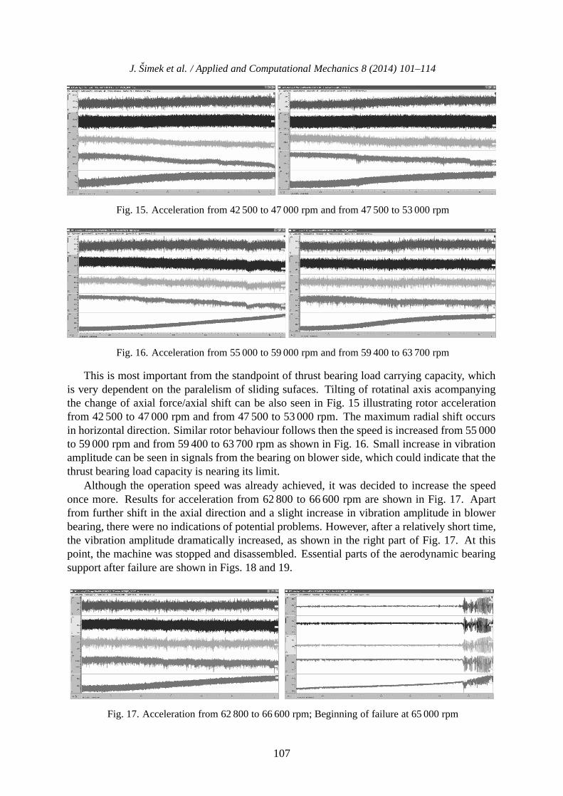
Fig. 15. Acceleration from 42 500 to 47 000 rpm and from 47 500 to 53 000 rpm
Fig. 16. Acceleration from 55 000 to 59 000 rpm and from 59 400 to 63 700 rpm
This is most important from the standpoint of thrust bearing load carrying capacity, whichis very dependent on the paralelism of sliding sufaces. Tilting of rotatinal axis acompanyingthe change of axial force/axial shift can be also seen in Fig. 15 illustrating rotor accelerationfrom 42 500 to 47 000 rpm and from 47 500 to 53 000 rpm. The maximum radial shift occursin horizontal direction. Similar rotor behaviour follows then the speed is increased from 55 000to 59 000 rpm and from 59 400 to 63 700 rpm as shown in Fig. 16. Small increase in vibrationamplitude can be seen in signals from the bearing on blower side, which could indicate that thethrust bearing load capacity is nearing its limit.
Although the operation speed was already achieved, it was decided to increase the speedonce more. Results for acceleration from 62 800 to 66 600 rpm are shown in Fig. 17. Apartfrom further shift in the axial direction and a slight increase in vibration amplitude in blowerbearing, there were no indications of potential problems. However, after a relatively short time,the vibration amplitude dramatically increased, as shown in the right part of Fig. 17. At thispoint, the machine was stopped and disassembled. Essential parts of the aerodynamic bearingsupport after failure are shown in Figs. 18 and 19.
Fig. 17. Acceleration from 62 800 to 66 600 rpm; Beginning of failure at 65 000 rpm
107
J. Simek et al. / Applied and Computational Mechanics 8 (2014) 101–114
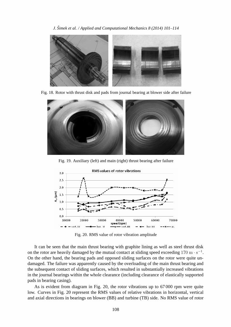
Fig. 18. Rotor with thrust disk and pads from journal bearing at blower side after failure
Fig. 19. Auxiliary (left) and main (right) thrust bearing after failure
Fig. 20. RMS value of rotor vibration amplitude
It can be seen that the main thrust bearing with graphite lining as well as steel thrust diskon the rotor are heavily damaged by the mutual contact at sliding speed exceeding 170 m · s−1.On the other hand, the bearing pads and opposed sliding surfaces on the rotor were quite un-damaged. The failure was apparently caused by the overloading of the main thrust bearing andthe subsequent contact of sliding surfaces, which resulted in substantially increased vibrationsin the journal bearings within the whole clearance (including clearance of elastically supportedpads in bearing casing).
As is evident from diagram in Fig. 20, the rotor vibrations up to 67 000 rpm were quitelow. Curves in Fig. 20 represent the RMS values of relative vibrations in horizontal, verticaland axial directions in bearings on blower (BB) and turbine (TB) side. No RMS value of rotor
108

J. Simek et al. / Applied and Computational Mechanics 8 (2014) 101–114
vibration amplitude in radial direction exceeded 2 μm. Vibrations in axial direction were lowerthan 3 μm in the whole speed range. These data reflect the very good level of rotor balancing aswell as the proper function of both the journal and thrust bearings. The only indication of thrustbearing overloading was the very slight vibration increase in the journal bearing at blower side.
According to calculation, the main thrust bearing was operating with gas film thicknesslower than 3 μm, which is an extremely low value for a bearing 50 mm in diameter. The ax-ial force acting on the thrust bearing is a resultant of pressures acting on the impellers andthe unloaded part of the thrust disk. Change of axial force direction at about 40 000 rpmwas caused by pressure increase at the turbine side, which was then amplified by the pres-sure acting on the other (now unloaded) side of the thrust disk. The development of axial forcewith speed is shown in diagram in Fig. 21. As can be seen from the diagram, at the speed of65 000 rpm axial force exceeded value of 150 N, scheduled for bearing design, almost threetimes. The change of axial force direction around 40 000 rpm was confirmed by the measureddata.
Fig. 21. Calculated axial force
4. Test stand modifications and new series of tests
An axial force analysis showed that it is necessary to reduce the thrust bearing load [8]. Laby-rinth seal was, therefore, installed behind the turbine impeller (see Fig. 22). The tests continuedby sequentially increasing the speed with similar rotor vibrations as in the previous tests. Sam-
Fig. 22. Labyrinth seal behind the turbine impeller
109
J. Simek et al. / Applied and Computational Mechanics 8 (2014) 101–114
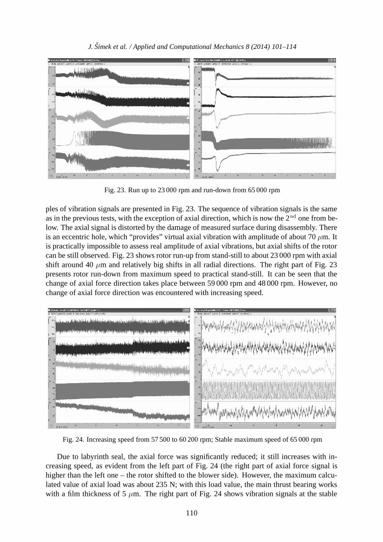
Fig. 23. Run up to 23 000 rpm and run-down from 65 000 rpm
ples of vibration signals are presented in Fig. 23. The sequence of vibration signals is the sameas in the previous tests, with the exception of axial direction, which is now the 2nd one from be-low. The axial signal is distorted by the damage of measured surface during disassembly. Thereis an eccentric hole, which “provides” virtual axial vibration with amplitude of about 70 μm. Itis practically impossible to assess real amplitude of axial vibrations, but axial shifts of the rotorcan be still observed. Fig. 23 shows rotor run-up from stand-still to about 23 000 rpm with axialshift around 40 μm and relatively big shifts in all radial directions. The right part of Fig. 23presents rotor run-down from maximum speed to practical stand-still. It can be seen that thechange of axial force direction takes place between 59 000 rpm and 48 000 rpm. However, nochange of axial force direction was encountered with increasing speed.
Fig. 24. Increasing speed from 57 500 to 60 200 rpm; Stable maximum speed of 65 000 rpm
Due to labyrinth seal, the axial force was significantly reduced; it still increases with in-creasing speed, as evident from the left part of Fig. 24 (the right part of axial force signal ishigher than the left one – the rotor shifted to the blower side). However, the maximum calcu-lated value of axial load was about 235 N; with this load value, the main thrust bearing workswith a film thickness of 5 μm. The right part of Fig. 24 shows vibration signals at the stable
110

J. Simek et al. / Applied and Computational Mechanics 8 (2014) 101–114
maximum speed of about 65 000 rpm. The peak to peak vibration amplitudes of all signals inradial direction did not exceed 5 μm. The RMS values of vibration amplitudes in radial direc-tion in dependence on speed are presented in Fig. 25. Sensor at the blower side in horizontaldirection (dotted line in Fig. 25) was damaged during the rotor failure in the 1st test and itscharacteristics cannot be considered as quite correct. The other 3 sensors show RMS values ofvibration amplitude lower than 1.5 μm in the whole speed range, i.e., extremely small valuesfor such a high speed.
Fig. 25. RMS values of rotor vibration amplitude in radial direction vs. speed
5. Final tests and machine disassembly
Final tests consisted of run-up and run-down cycles and of cycling from minimum speed tomaximum speed. In the 1st part of the test, the machine completed 1 000 cycles from standstillto the maximum speed of 60 000 rpm with a 1 minute-long run followed by a run-down to standstill. The 2nd part of the test consisted of 500 cycles of 5 minute run at 30 000 rpm, increasingspeed to 60 000 rpm, 5 minute run at this speed, and again decreasing speed to 30 000 rpm etc.After finishing the 2nd test, the machine was disassembled. Two important facts were found outwhen examining the bearing parts:
1. A small amount of oil from the system of pressurized air driving the machine penetratedinto main thrust bearing, as documented in Fig. 26. The oil mixed with the graphite par-ticles loosened from the bearing lining significantly increased the starting torque duringthe rotor run-up. The presence of oil at the graphite lining is by no means desirable anddoes not reduce the wear of sliding surfaces during the run-up and run-down; it has ratherthe opposite effect.
2. Some of the nuts securing the pad position and by that also basic bearing clearance werecompletely or partly loosened. Pertinent pads were then pressed by their elastic supportsto the shaft so that the bearing support lost its biggest advantage in comparison with thefoil bearings, in the form of a low starting torque. On the other hand, it showed that thetilting pad bearings with elastically supported pads can operate in the same way as thefoil bearing, i.e., without basic bearing clearance. Similarly as in the foil bearings, thepads are separated from the shaft surface and a full gas film is generated when the rotorachieves certain speed.
111
J. Simek et al. / Applied and Computational Mechanics 8 (2014) 101–114
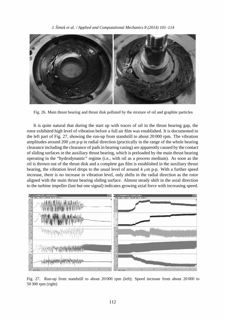
Fig. 26. Main thrust bearing and thrust disk polluted by the mixture of oil and graphite particles
It is quite natural that during the start up with traces of oil in the thrust bearing gap, therotor exhibited high level of vibration before a full air film was established. It is documented inthe left part of Fig. 27, showing the run-up from standstill to about 20 000 rpm. The vibrationamplitudes around 200 μm p-p in radial direction (practically in the range of the whole bearingclearance including the clearance of pads in bearing casing) are apparently caused by the contactof sliding surfaces in the auxiliary thrust bearing, which is preloaded by the main thrust bearingoperating in the “hydrodynamic” regime (i.e., with oil as a process medium). As soon as theoil is thrown out of the thrust disk and a complete gas film is established in the auxiliary thrustbearing, the vibration level drops to the usual level of around 4 μm p-p. With a further speedincrease, there is no increase in vibration level, only shifts in the radial direction as the rotoraligned with the main thrust bearing sliding surface. Almost steady shift in the axial directionto the turbine impeller (last but one signal) indicates growing axial force with increasing speed.
Fig. 27. Run-up from standstill to about 20 000 rpm (left); Speed increase from about 20 000 to50 300 rpm (right)
112

J. Simek et al. / Applied and Computational Mechanics 8 (2014) 101–114
Fig. 28. Bearing pads at the turbine side (left) and blower side (right) after disassembly
Fig. 29. Cleaned rotor
As can be seen from Fig. 28, the bearing pads at the turbine side (next to the thrust bearing)were also somewhat polluted by oil in contrast to the pads from the bearing at the blower side,which stayed quite clean. After shaft cleaning, it is evident that the sliding surfaces are notdamaged and neither on the thrust disk and neither on the shaft at the journal bearing locations(see Fig. 29). Traces at the outer diameter of the thrust disk indicate that there was a slight andvery short contact of sliding surfaces, but the damage is very small and the rotor and bearingsare able to operate further quite satisfactorily.
6. Conclusions
An air cycle machine (ACM) with rolling bearing rotor support was reconstructed and used as atest stand for the verification of air bearing properties. The 1st part of the test proved operabilityof the air bearing support, consisting of elastically supported tilting pad journal bearings andspiral groove thrust bearings, up to maximum speed of 65 000 rpm. The failure occurred due toexcessive axial force, which exceeded the nominal value for thrust bearing design almost threetimes.
Installation of a labyrinth seal behind the turbine impeller proved effective in reducing theaxial load to its maximum value about 235 N, with which main thrust bearing works with filmthickness about 5 μm. Up to the maximum speed of 65 000 rpm, the rotor runs with RMSvalues of vibration amplitudes up to 1.5 μm, which corresponds to peak-to-peak values lowerthan 4.5 μm. Such a small values of rotor vibration confirm correct function of bearing supportand a very good level of rotor balancing.
113

J. Simek et al. / Applied and Computational Mechanics 8 (2014) 101–114
The aerodynamic bearing support operability and reliability was further confirmed by a serieof 1 000 starts and stops and 500 cycles of acceleration from 30 000 rpm to 60 000 rpm and backto 30 000 rpm.
A smaller ACM with maximum operating speed of 95 000 rpm was designed and is preparedfor manufacture (Fig. 30), as machine dimensions and weight are the most important parametersfor flight applications.
Fig. 30. Design of a smaller ACM variant
Acknowledgements
This work was supported by the Technology Agency of the Czech Republic under project PIDTA02011295 “Verification of air bearing technology”.
References
[1] Agrawal, L., Foil air/gas bearing technology — an overview, ASME publication 97-GT-347.[2] Howard, S. A., Bruckner, R. J., DellaCorte, CH., Radil, K. C., Gas foil bearing technology ad-
vancement for Brayton cycle turbines, NASA/TM-2007-214470.[3] Howard, S. A., Bruckner, R. J., Radil, K. C., Advancement towards oil-free rotorcraft propulsion,
NASA/TM-2010-216094.[4] Simek, J., Application of a new type of aerodynamic bearing in power gyroscope, Engineering
Mechanics 19 (5) (2012) 359–368.[5] Simek, J., Design of aerodynamic bearing support of the test stand, Technical report TECHLAB
No. 12–417, 2012. (in Czech)[6] Simek, J., Design of the test stand for verification of air bearing technology, Technical report
TECHLAB No. 12–420, 2012. (in Czech)[7] Simek, J., Experimental verification of air bearing properties, Technical report TECHLAB
No. 13–413, 2013. (in Czech)[8] Simek, J., Experimental verification of air bearing properties. Phase 2 — after reduction of axial
force, Technical report TECHLAB No. 14–401, 2014. (in Czech)
114


![[PPT]Design of Sliding Contact Bearing/Journal Bearing · Web viewIntroduction A bearing is a machine element which support another moving machine element (known as journal). It permits](https://img.pdfslide.us/doc/110x75/5aaceacc7f8b9aa9488d9fa7/pptdesign-of-sliding-contact-bearingjournal-bearing-viewintroduction-a-bearing.jpg)